conductance level switch - abb ltd · cp2-0200-1 rev nc (04-2009) drr0167 6 conductance level...
TRANSCRIPT

Conductance Level Switch
Installation & Operation Manual
For the latest version of this manual, visit kteksolidslevel.com.
CP2

CP2-0200-1 Rev nc (04-2009) DRR0167 2
Conductance Level Switch CP2
TABLE OF CONTENTS
1.0 GENERAL DESCRIPTION 3
2.0 SPECIFICATIONS 4
3.0 OPERATION 6
4.0 INSTALLATION 10
5.0 CALIBRATION 11
6.0 MAINTENANCE & TROUBLESHOOTING 13
7.0 WARRANTY 14

CP2-0200-1 Rev nc (04-2009) DRR0167 3
Conductance Level Switch CP2
1.1 The K-TEK Model CP2 Conductivity Switch produces ON-OFF control as a conductive material touches the tip of its sensing electrode. When used in conjunction with non-metallic vessels, a second (ground reference) electrode is required. In some cases, it can be used to detect an interface between non-conductive and con-ductive liquids. Applications requiring differential switching such as sump pump control can be accomplished with the differential option.
1.2 The basic unit, when configured for fixed sensitivity, will produce switch action when the electrode to ground
resistance is less than 13,000 ohms. Some process media require operation at higher resistance and would require the unit to be configured for adjustable sensitivity.
1.3 The Model CP2 electronics are suitable for either integral or remote-mounting. The remote electronics are
attached via an interconnecting cable to the vessel mounted sensing electrode terminating enclosure. 1.4 Electrodes should be mounted vertically from the top of the tank to prevent a conductive buildup from bridging
to the vessel wall. Solid electrodes are available in lengths up to 10 feet. Flexible cable electrodes are also available for greater lengths. Individual elements of multi-electrode holders are insulated to within one inch of their tip to additionally protect against bridging and prevent contact between adjacent elements. Application assistance is available through our distributors as well as from the factory.
1.0 GENERAL DESCRIPTION

CP2-0200-1 Rev nc (04-2009) DRR0167 4
Conductance Level Switch CP2
Environmental
Electronics Enclosure NEMA 4 (Integral or Remote Mount)
Electrode Enclosure NEMA 3 (Remote Mount Only)
Operating Temperature
Electronics -40°C to +85°C (-40°F to 185°F) Electrodes See electrode compatibility chart Electrical Supply Power 95-130 VAC, 50-60 Hertz, 3 Watts 190-260 VAC, 50-60 Hertz, 3 Watts 12 VDC Regulated Output (1) DPDT Relay Relay Contact Rating Resistive—5 Amp 250 VAC; 5 Amp 30 VDC Inductive—1/10 HP 125, 250 VAC
2.0 SPECIFICATIONS
CP2 12 VDC Powered Electronics CP2 120 VAC Powered Electronics

CP2-0200-1 Rev nc (04-2009) DRR0167 5
Conductance Level Switch CP2
Figure 2.2: Cable Electrode Enclosure Dimensions
Figure 2.3: PVC Electrode Enclosure Dimensions Figure 2.4: Aluminum Electrode Enclosure Dimensions
CP2-0200-1 Rev nc (04-2009) DRR0167 6
Conductance Level Switch CP2
3.0 Operation 3.1 A very small AC signal (approximately 1.5 Vp-p) is passed through the process media from the sensing
electrode to the ground reference. A detector determines the presence or absence of the media by comparing its resistance with the setpoint resistance. An AC signal is used to overcome plating problems incurred by using a DC source. The unit is ideal for detecting the presence, absence or level of water, or other polar fluids.
3.2 A time delay function is included as a standard item in the CP2. It is used primarily to eliminate nuisance
alarms which may be caused by splashing or wave action in the vessel. The time delay is adjustable from 0 to 30 seconds. It may be set to operate on rising level or failing level.
For example, when the time delay is set to actuate on rising level, the red LED will turn on instantaneously
whenever the liquid in the vessel touches the probe. However, the relay will not change condition until the material has been in continuous contact with the probe for the amount of time the delay is set for. When material falls off of the probe, the relay and the red LED will both change condition instantaneiously.
When the time delay is set to actuate on failing level, the relay and the red LED both operate instantaneously
when material touches the probe. When material falls off of the probe, the relay will not change condidtion until the time delay has elapsed.
3.3 Optional differential switching is accomplished by using two sensing electrodes, of which one is longer than
the other. The control relay toggles when the process media contacts the upper (short) electrode and it is electronically “latched-in” through the lower (long) electrode. Therefore, the switching differential is the difference between the lengths of the two sensing electrodes.
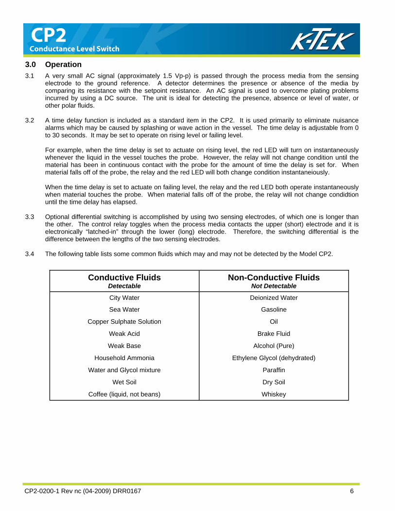
3.4 The following table lists some common fluids which may and may not be detected by the Model CP2.
Conductive Fluids Detectable
Non-Conductive Fluids Not Detectable
City Water Deionized Water
Sea Water Gasoline
Copper Sulphate Solution Oil
Weak Acid Brake Fluid
Weak Base Alcohol (Pure)
Household Ammonia Ethylene Glycol (dehydrated)
Water and Glycol mixture Paraffin
Wet Soil Dry Soil
Coffee (liquid, not beans) Whiskey
CP2-0200-1 Rev nc (04-2009) DRR0167 7
Conductance Level Switch CP2

CP2-0200-1 Rev nc (04-2009) DRR0167 8
Conductance Level Switch CP2

CP2-0200-1 Rev nc (04-2009) DRR0167 9
Conductance Level Switch CP2
SE
NS
ITIVITY
ADJ
FIXED
DIFF
ALA
RM
TIME
DE
LAY
RIS
E FALL
LO
HI
"FAIL-SAFE"
AS
I INS
TRU
MEN
TS INC
.H
OU
STO
N, TEXAS
"FAIL-SAFE"
HI
LO
RIS
E FA
LL
TIME
DE
LAYA
LAR
M
DIFF
FIXED
ADJ
SE
NS
ITIVITY
NO
2
C2
NC
2N
C1
C1
NO
1
1P
RO
BE
PR
OBE
2
CO
MM
ON
PR
OBE
3.0"
PR
OBE
ELECTRONIC CARD DIMENSION
CO
MM
ON
2P
RO
BE
PR
OBE
1
NO
1
C1
NC
1N
C2
C2
NO
2
C2
C2
2.63"4.38"

CP2-0200-1 Rev nc (04-2009) DRR0167 10
Conductance Level Switch CP2
4.0 Installation 4.1 After unpacking the unit, inspect it for any evidence of shipping damage. Any claims for damage due to
shipement must be filed with the carrier who handled the package(s). 4.2 Select a mounting location in accordance with good instrument practice. Reliability will be enhanced if the
location is free of excessive vibration or environmental temperatures outside the specific range. Be sure there is sufficient clearance around the mounting position to allow for the turning radius as the electrode holder is put into place. Additional clearances must be allowed to enable insertion of long rigid probes into vessel opening and removal of the housing cover. CAUTION: When making connections to the vessel, observe all safety requirements of the area where the work is being done. Be especially careful of pressure vessels.
4.3 The Model CP2 may not function properly if: • the unit does not have an adequate ground reference. • the sensing electrode comes into contact with the ground reference. • the sensing electrode is located near a material inlet or outlet port. • a conductive material has bridged between the sensing electrode and the ground reference.
If any of the above apply to your application, do not install the Model CP2 and contact your local distributor, representative or the K-TEK factory for instructions. 4.4 The Model CP2 may be damaged if:
• the temperature in the electronics housing exceeds –40° to 185°F (-40° to 85°C). • the sensing electrode rated temperature or pressure is exceeded. • the electronics are subjected to excessive vibration or shock. • probe is mounted directly in the flow of material. • if the supply power is not within the ratings for the particular unit. • if relay contacts are subjected to a current in excess of their rating.
If any of the above apply to your application, do not install the Model CP2 and contact your local distributor, representative or the K-TEK factory for instructions. 4.5 Mount the sensing electrode holder using a suitable NPT fitting or flange. WARNING: Turn off and lock out all power before beginning installation.
CAUTION: Install a conduit seal with a drain or use a drain loop or other means to prevent condensate from entering the housing. Failure to do so will allow moisture to enter the housing. This can cause equipment damage or malfunction.
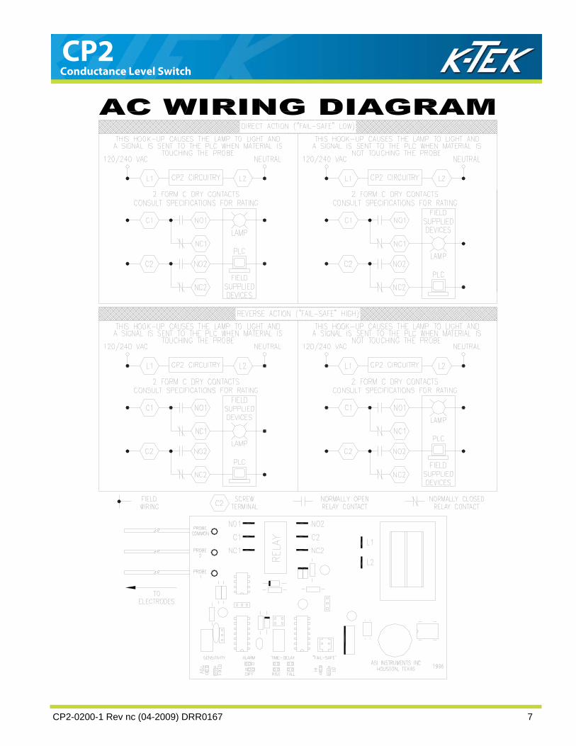
4.6 Wire the Model CP2 in accordance with one of they typical wiring diagrams or as may be required by the particular application in which the unit is used. Because of the extremely wide range of control and/or alarm applications in which the unit may be used, it is not possible to show all conceivable wiring diagrams. Consult your distributor or K-TEK if assistance is required. CAUTION: Be sure all wiring conforms to the requirements of the National Electric Code and any enforcing authorities or agencies having jurisdiction over the installation. Insure that any special conditions, such as areas having explosion hazards, are given full consideration.

CP2-0200-1 Rev nc (04-2009) DRR0167 11
Conductance Level Switch CP2
5.0 Calibration 5.1 The basic unit is equipped with jumpers to select either fixed or adjustable sensitivity. In the “FIXED” mode
the unit requires no calbiration. In the “ADJUSTABLE” mode, the calibration potentiometer enables the Model CP2 to be calibrated for a specific installation. Once calibrated, no additional adjustment should be required unless the installation is change or the unit is moved to a different location. The procedure for setting the calibration potentiometer is outlined in the section below.
5.2 The “Fail-Safe” selector is used to determine the mode of operation of the relay. If the selector is placed in
the HI position, the relay will be energized until the material in the vessel touches the sensing electrode, at which time the relay will be de-energized and the RED LED will turn on. If the selector is placed in the LO position, the realy will be de-energized until the material in the vessel touches the sensing electode, at which time the realy will energize and the RED LED will turn on. There are no devices which are absolutely “Fail-Safe” means, in the event of loss of power and some component failures, the instrument will indicate an alarm condition. If your application needs abosolute Fail-Safe, a back-up instrument or redundant system must be installed.
5.3 The green relay indicator LED depticts the status of the control relay. It is ON when the relay coil is energized
and OFF when the realy coil is de-energized. This light is helpful when calibrating units with the time delay. The green LED always indicates the status of the relay, on when the relay is energized and off when the relay is de-energized. The red LED always indictates whethere material is touching the probe, ON when material is touching and OFF when material is not touching.
There are four possible combinations of operation for the red and green LED’s, as shown in the following table:
Material Activity Time Delay Setting “Fail Safe” Setting Red LED Condition Green LED Condition
Rises to touch probe Falls off of probe
RISING RISING
LO LO
Instant ON Instant OFF
Delay ON Instant OFF
Rises to touch probe Falls off of probe
RISING RISING
HI HI
Instant ON Instant OFF
Delay OFF Instant ON
Rises to touch probe Falls off of probe
FALLING FALLING
LO LO
Instant ON Instant OFF
Delay ON Instant OFF
Rises to touch probe Falls off of probe
FALLING FALLING
LO LO
Instant ON Instant OFF
Delay OFF Instant ON
5.4 READ ALL STEPS BEFORE ATTEMPTING THIS CALIBRATION. ALARM CALIBRATION (For units utilizing adjusting sensitivity) Step 1 Rotate the SENSITIVITY and TIME DELAY adjustments fully counter clockwise (FCCW) 20 turns or until a
click is heard for every complete rotation. Step 2 Manually control the increase of the material level until it is above the tip of the sensing electrode. If switch
action has not occurred, rotate the SENSITIVITY adjustment clockwise (CW) until it does. In noisy environments where detection of relay switching is difficult, observing the RED LED material indicator light during potentiometer adjustment is recommended.
Step 3 Material control can now be restored to the output relay. Step 4 Calibration is now complete.

CP2-0200-1 Rev nc (04-2009) DRR0167 12
Conductance Level Switch CP2
DIFFERENTIAL SWITCHING CALIBRATION (For units utilizing adjustable sensitivity) Step 1 Rotate the SENSITIVITY and TIME DELAY adjustments fully counter clockwise (FCCW) 20 turns or until a
click is heard for every complete rotation. Step 2 Manually control the increase of the material level until it is above the tip of the shortest (upper) sensing
electrode. If switch action has not occurred, rotate the SENSITIVITY adjustment clockwise (CW) until it does. In noisy environments where detection of relay switching is difficult, observing the RED LED material indicator light during potentiometer adjustment is recommended.
Once the control relay switches, the deterctor circuitry is connected to the longest (lower) sensing electrode
that is now submerged into the material level and latches the relay. No further adjustment necessary. The control relay will not return to its original state until the material level falls below the tip of the longest (lower) sensing electrode to insure proper switching has occurred.
Step 3 Material control can now be restored to the output relay. Step 4 Calibration is now complete. TIME DELAY ADJUSTMENT The TIME DELAY potentiometer is used to ajduste the length of time an alarm condidtion must persist before
the unit will indicate an alarm. This adjustment has 20 turns and slips for free-wheeels at either end of its travel. Time delay can be utilized with a rising product level, a falling product level or simultaniously with a rising and falling product level. Transition from alarm condition to the normal condition is instantaneous. The unit is shipped wit the time delay preseet at the minimum (potentiometer turned fully counterclockwise). Each clockwise turn of the potentiometer will add approximately 1.5 seconds to the length of the time delay.

CP2-0200-1 Rev nc (04-2009) DRR0167 13
Conductance Level Switch CP2
6.0 Maintenance and Troubleshooting No routine maintenance is required other than keeping the interior of the unit clear of moisture and other contaminants. The CP2 consists of three main sub-assemblies: the electronic board, the sensing electrode and the sensor interconnecting cable. The following troubleshooting guide will assist in identifying the source of your specific problem. Note: The following procedures require power to be applied to the unit with the cover removed. Extreme care should be used when working aorund exposed live circuits to avoid personal injury or death due to electrical shock. Always insure the unit is properly grounded. 6.1 Functional Check Disconnect the wiring between the sensing probe and the electronics boards. Do not disconnect the supply power wiring. Turn the TIME DELAY adjustment potentiometer fully counterclockwise and not the state of the RED and GREEN LED’s. Use a test jumper, or other suitable shorting wire, to momentarily conncet “PROBE COMMON” and “PROBE 1” on the electronics card. If control relay switch action occurs as the two terminals are connected, the electronics card is functioning correctly. If the source of the problem can not be identified, additional testing or consulting the factory may be required. 6.2 Relay Check An ohmeter can be used to test the continuity of the contacts of the double-pole, double throw (DPDT) control relay. Operational problems frequently are traced to errors in wiring to the realy. Commonly, the difficulty arises from a misunderstanding of the Normally open/Normally closed terminology or a belief that power will be supplied from the realy contacts. Standard relay terminology refers tot eh “shelf state,” that is, unpowered condtion of the relay. When the relay is unpowered, continuity exists between the Normally Closed and Common terminals and no continuity exists between the Normally Open and Common terminals. When the relay is energized, continuity exists between the Normally Open and Common terminals and no continuity exists between the Normally Closed and Common terminals. Note: The relay is simply an electricity operated switch—opening or closing contacts. Power is not supplied by the relay, but it controls power that is provided by field wiring. 6.3 Sensing Electrode Tests Operational problems often can be traced to improper or incorrect installation of the sensing electrode holder. The use of large quantities of TEFLON® thread tape on metal electrode holders can contribute to a loss of ground integrity and is not recommended. The following tests can be performed using and analog (non-digital) ohmmeter to measure the resistance between the sensing electrode(s) and ground. Disconnect all sensing electrode wires from the electronics card. Lower the level of the material in the vessel until it is below the sensing electrode(s). Measure the resistance between the sensing electrode wire(s). Measured resistance should be infinite.

CP2-0200-1 Rev nc (04-2009) DRR0167 14
Conductance Level Switch CP2
5.0 WARRANTY INFORMATION 3 YEAR WARRANTY FOR: ShieldPoint™300 & ShieldPoint™400 capacitance switches. 2 YEAR WARRANTY FOR: WT2000 radar level transmitters; RP paddle switches; A02, A75, & A77 RF capacitance level switches and A33 & A38 RF capacitance level transmitters; A22 Speed Switch; CP2 Conductance Switch. 1 YEAR WARRANTY FOR: LaserTrak™ and EasyTrak™ series laser transmitters; DPM100 digital indicators; KVIEW series digital indicators and con-trollers; GranuPoint™ and SlurryPoint™ vibrating fork switches, SoliTrak™ Electro-Mechanical Continuous Measuring De-vices, SonikTrak™ultrasonic level transmitters & transducers. SPECIAL WARRANTY CONSIDERATIONS: ASI will honor OEM warranties for items not manufactured by ASI (i.e. Palm Pilots). ASI will repair or replace, at ASI’s election, defective items which are returned to ASI by the original purchaser within the period specified above from the shipment date of the item and which is found, upon examination by ASI, to its satisfac-tion, to contain defects in materials or workmanship which arose only under normal use and service and which were not the result of either alterations, misuse, abuse, improper or inadequate adjustments, applications or servicing of the prod-uct. ASI’s warranty does not include onsite repair or services. Field service rates can be supplied on request. If a product is believed to be defective, the original purchaser shall notify ASI and request a Returned Material Authoriza-tion before returning the material to ASI, with transportation prepaid by the purchaser. (Request door to door delivery via Houston International Airport located in Houston, TX, USA.) The product, with repaired or replaced parts, shall be returned to the purchaser at any point in the world with transportation prepaid by ASI for best-way transportation only. ASI is not responsible for expedited shipping charges. If the product is shipped to ASI freight collect, then it will be returned to the customer freight collect. If inspection by ASI does not disclose any defects in material or workmanship, ASI’s normal charges for repair and ship-ment shall apply (minimum 100.00 USD). The materials of construction for all ASI products are clearly specified and it is the responsibility of the purchaser to deter-mine the compatibility of the materials for the application. THE FOREGOING WARRANTY IS ASI'S SOLE WARRANTY AND ALL OTHER WARRANTIES EXPRESSED, IMPLIED, OR STATUTORY, INCLUDING ANY IMPLIED WARRANTY OF MERCHANTABILITY OF FITNESS FOR A PARTICULAR PURPOSE, ARE EXCLUDED AND NEGATED TO THE MAXIMUM EXTENT PERMITTED BY LAW. NO PERSON OR REPRESENTATIVE IS AUTHORIZED TO EXTEND ANY OTHER WARRANTY OR CREATE FOR ASI ANY OTHER LI-ABILITY IN CONNECTION WITH THE SALE OF ASI’S PRODUCTS. THE REMEDIES SET FORTH IN THIS WAR-RANTY ARE EXCLUSIVE OF ALL OTHER REMEDIES AGAINST ASI. ASI SHALL NOT BE LIABLE FOR ANY CONSE-QUENTIAL, INCIDENTAL, OR SPECIAL DAMAGES OF ANY KIND. ASI’S SOLE OBLIGATION SHALL BE TO REPAIR OR REPLACE PARTS (FOUND TO BE DEFECTIVE IN MATERIALS OR WORKMANSHIP) WHICH ARE RETURNED BY THE PURCHASER TO ASI.

CP2-0200-1 Rev nc (04-2009) DRR0167 15
Conductance Level Switch CP2

CP2-0200-1 Rev nc (04-2009) DRR0167 16
Conductance Level Switch CP2
For the latest version of this manual, visit kteksolidslevel.com.
K-TEK Solids Level 6100 West by Northwest #140
Houston, TX 77040 USA Tel: (1) 713.462.7665
Fax: (1) 713.462.7684 Email: [email protected]
Website: kteksolidslevel.com