conditioning your ambient,maximising your comfort. conditioning, purifying. conditioning your...
TRANSCRIPT

Cooling, conditioning, purifying.
Conditioning your ambient, maximising your comfort.
OCEANOCEAN HOCEAN OCEAN/ME
Refrigeratori di liquido condensati ad acqua, pompe di calore e unità motoevaporanti(Potenza frigorifera 4,2 - 205 kW, potenza termica 4,6 - 247 kW, compressori scroll)
Water-cooled liquid chillers, heat pumps and condenserless units (Cooling capacity 4,2 - 205 kW, heating capacity 4,6 - 247 kW, scroll compressors)
R407C 50Hz

Conditioning your ambient,maximising your comfort.
Cooling, conditioning, purifying.

Indi
ce -
Ind
ex
OCEAN
Specifiche tecnicheTechnical specifications
Guida alla selezioneSelection guide
Dati tecnici e prestazioni Performance and technical data
Perdite di carico Pressure drops
Limiti di funzionamento e coefficienti correttiviWorking limits and correction factors
Disegni di ingombroOverall dimensions
Guida all’installazioneInstallation guide
2
8
12
44
47
48
56

OC
EAN
SPECIFICHE TECNICHE - TECHNICAL SPECIFICATIONS
1 General2 Versions3 Nameplate4 Testing5 Compressors6 Evaporators7 Condensers8 Cooling circuit9 Structure and casing10 Electrical panel11 Control12 External hydraulic group (additional kit)13 Options, kits and special designs
1. General
The OCEAN series of chillers, heat pumps and condenserless units are designed for indoor installation (IP22 protection rating), water cooled with hermetic compressors rotary (first 3 models) and scroll (for all the other models). The series is available with 16 models: 9 models with one cooling circuit and one compressor (inversion cycle on the refrigerant side for the heat pump), 4 models with one cooling circuits with tandem compressors (inversion cycle on the refrigerant side for the heat pump), 3 models with two cooling circuit and one compressor per circuit (inversion cycle on the water side for the heat pump). Every OCEAN is controlled by a microprocessor “IC121” type for the units with one cooling circuit and “IC281” type for the units with two cooling circuits. This two microprocessors management all the main functions, e.g. alarms and setting. The refrigerant gas utilized is R407C. The condensers and the evaporators, for all machines, are heat exchangers stainless steel plate-type. Condenserless version are supplied without condensers and are predisposed refrigerant valve before IN/OUT refrigerant connections. For the first three models power supply is single-phase and three-phase for all other models. All units are made with high quality, top brand name components and were designed, produced and tested in compliance with ISO 9001 standards.The standard product, meant for the CEE and EFTA countries, is subject to:• Electromagnetic Compatibility Directive 89/336 and subsequent
modifications;• Machinery 98/37/EC;• Low Voltage Directive 2006/95/EC;• Pressure Equipment 97/23/EC.The electrical cabinet is constructed in compliance with standard EN 60335-1.
All the data presents in this catalogue refers to the standards units at the nominal conditions of working (except when differently specified).
2. Versions
OCEAN is available in the followings versions:
“OC xxx” chiller version;
“HOC xxx” heat pump version; with inversion on refrigerant circuit side in the models from 018 to 350 and inversion on the water side for the other models;
“OC xxx/ME” condenserless version.
3. Nameplate
The units are identified by its nameplate: OC / HOC XXX / ME
condenserless version;
nominal power pf the compressors, in HP;
Ocean / HOcean.
1 Generalità2 Versioni3 Sigla4 Collaudo5 Compressori6 Evaporatori7 Condensatori8 Circuito frigorifero9 Struttura e carenature10 Quadro elettrico11 Controllo12 Gruppo idraulico esterno (kit addizionale)13 Opzioni, kit ed esecuzioni speciali
1. Generalità
I refrigeratori di liquido, le pompe di calore e le unità motoevaporanti della serie OCEAN sono unità progettate per uso in ambiente riparato (grado di protezione IP22), condensate ad acqua con compressori ermetici rotativi (primi 3 modelli) e scroll (tutti gli altri). La gamma è composta da 16 modelli: 9 modelli monocircuito monocompressore (inversione di ciclo lato refrigerante per le pompe di calore), 4 modelli monocircuito con compressori in tandem (inversione di ciclo lato refrigerante per le pompe di calore), 3 modelli bicircuito e un compressore per circuito (inversione lato acqua per le pompe di calore). La gestione degli OCEAN è affidata al controllo a microprocessore “IC121” per le unità monocircuito, e “IC281” per le unità bicircuito. Questi due controlli gestiscono tutte le funzioni principali, tra cui regolazioni, allarmi ed interfaccia con l’esterno. Il fluido frigorigeno utilizzato è l’R407C. I condensatori e gli evaporatori sono del tipo a piastre saldobrasate in acciaio inox. La versione motoevaporante non prevede il condensatore ed è provvista di rubinetti IN/OUT sul circuito frigorifero. L’alimentazione elettrica è monofase nei primi 3 modelli e trifase altrove. Tutte le macchine sono realizzate utilizzando componenti di primaria marca, e sono progettati, prodotti e controllati in conformità alle norme ISO 9001.Il prodotto standard, destinato agli stati CEE ed EFTA, è soggetto a:• Direttiva Compatibilità Elettromagnetica 89/336 e successive modifiche;• Direttiva Macchine 98/37/CE;• Direttiva Bassa Tensione 2006/95/CE;• Apparecchiature in pressione 97/23/CE.Il quadro elettrico è realizzato in conformità alle norme EN 60335-1.
Tutti i dati riportati in questo catalogo sono riferiti a macchine standard e a condizioni nominali di funzionamento (salvo quando diversamente specificato).
2. Versioni
La serie OCEAN è disponibile nelle seguenti versioni:
“OC xxx” versione chiller;
“HOC xxx” versione pompa di calore; con inversione sul circuito frigorifero nei modelli dal 018 al 350 ed inversione lato acqua nei modelli rimanenti;
“OC xxx/ME” versione motoevaporante.
3. Sigla
Le macchine sono identificate dalla sigla: OC / HOC XXX / ME
solo versione motoevaporante;
potenza nominale dei compressori in HP;
Ocean / HOcean.
®
2
OC
EAN

®
3
4. Collaudo
Ogni macchina prodotta viene collaudata in cabina di controllo per valutarne il corretto funzionamento, sia nelle condizioni operative più significative, che in quelle più gravose; in particolare:• si verifica il corretto montaggio di tutti i componenti e l’assenza di fughe
di fluido refrigerante;• si eseguono i test di sicurezza elettricicome prescritto dalla CEI EN603351 e CEI EN60335-2-40;• si verifica il corretto funzionamentodel controllo a microprocessore ed
il valore di tutti i parametri d’esercizio;• si verificano le sonde di temperatura ed i trasduttori di pressione;• realizzando il funzionamento alle condizioni nominali in ambiente
controllato si verificano: la taratura della valvola termostatica, la carica di fluido frigorigeno, le temperature di evaporazione e di condensazione, il surriscaldamento ed il sottoraffreddamento e la potenza frigorifera resa;
• il collaudo delle pompe di calore avviene sia in modalità raffreddamento che riscaldamento.
Per le unità motoevaporanti il collaudo non include il test di funzionamento. Le verifiche funzionali prevedono la simulazione, tramite ponti elettrici, di tutte le condizioni d’intervento dei sistemi di gestione e delle protezioni.
All’atto dell’installazione le macchine richiedono solo le connessioni elettriche ed idrauliche, e per le versioni motoevaporanti il collegamento ad uno scambiatore remoto, assicurando un alto livello di affidabilità.
5. Compressori
I compressori impiegati sono di tipo ermetico: rotativo, con separatore d’aspirazione integrato per i modelli 018-022-030 e scroll per tutti gli altri; in particolare i modelli dal 200 al 350 utilizzano due compressori collegati in parallelo nello stesso circuito per incrementare gli indici di prestazione ai carichi parziali, che rappresentano la quota principale nel corso della vita operativa di una macchina dedicata alla climatizzazione, massimizzando gli indici di prestazione stagionale ESEER (*) ed IPLV (*). Questa soluzione, tramite la funzione di “unloading”, permette altresì l’avviamento dell’impianto, ed il funzionamento della macchina, anche a condizioni molto differenti da quelle nominali.I compressori delle pompe di calore e delle unità motoevaporanti sono dotati di resistenza di riscaldamento carter.I compressori ermetici impiegati presentano numerosi vantaggi tra i quali: ridotte perdite di carico in aspirazione grazie all’assenza di valvole, grande resistenza agli eventuali colpi di liquido, elevato rendimento di compressione, elevata aspettativa di vita con manutenzione inesistente, bassissime vibrazioni e livello di rumorosità.Gli avvolgimenti del motore elettrico sono a 2 poli e sono protetti dalle sovra-temperature, derivanti da un’eventuale funzionamento anomalo, da un dispositivo interno di protezione dai sovraccarichi.Sono sempre montati su antivibranti in gomma, e sono installati in un vano, acusticamente isolato tramite materassino fonoassorbente bugnato, i cui pannelli laterali sono amovibili per la completa accessibilità.
(*) Gli indici di prestazione stagionale ESEER (European Seasonal Energy Efficiency Ratio) proposto e utilizzato nel contesto progettuale europeo e IPLV (Integrated Part Load Value) proposto dallo Standard ARI americano, caratterizzano l’efficienza media ponderata di un chiller destinato al condizionamento. Questi indici esprimono, molto meglio del EER, il rapporto tra l’effetto utile (energia totale sottratta agli ambienti) e la spesa energetica (energia elettrica consumata) propri di una macchina frigorifera nel corso dell’intera stagione di funzionamento. In relazione alle differenti condizioni operative, e alla frequenza con cui esse si raggiungono, tali indicatori vengono calcolati assegnando un peso energetico differente alle corrispondenti prestazioni dell’unità.Ad esempio ESEER = 5 significa che, nel corso di un’intera stagione di funzionamento, per ogni 5 kWh termici sottratti agli ambienti da raffrescare verrà mediamente speso 1 kWh di energia elettrica.
4. Testing
Each unit is tested in a test chamber in order to check correct operation both in the most representative operating conditions and in the most demanding conditions; the following aspects are checked in particular:• correct installation of all components and possible refrigerant
leaks;• electrical safety tests as prescribed by CEI EN60335-1 and CEI
EN60335-2-40;• correct operation of the microprocessor controller together with the
values of all operating parameters;• temperature probes and pressure transducers;• with the unit running in nominal conditions, the following checks
are performed: thermostatic valve calibration, refrigerant charge, evaporation and condensation temperatures, superheating and subcooling and the cooling duty;
• testing of heat pumps is performed in both cooling and heating mode.
For condenserless units the procedure does not include a running test. The functional checks carried out involve simulation of all trip situations of the control systems and protections, achieved by installing jumpers.
At the time of installation the units require exclusively electrical and hydraulic connections, and, in the case of condenserless versions, connection to a remote exchanger, ensuring a high level of reliability.
5. Compressors
The units are equipped with hermetic scroll type compressors: rotary, with built-in intake separator for models 018-022-030 and scroll for all the others; specifically, models from 200 to 350 use two compressors connected in parallel in the same circuit to make it possible to achieve superior COP levels at partial loads, which account for the largest portion of the working life of an air conditioning unit, maximising ESEER (*) and IPLV (*) seasonal performance indices. This solution, by means of the “unloading” function, likewise allows system start-up and operation of the unit also in conditions that are very different from the nominal values. The compressors of the heat pumps and of the condenserless units are equipped with cranckcase heater.The hermetic compressors installed have a number of advantages including: reduced pressure drops on the suction side thanks to the absence of valves, significant resistance to possible liquid pressure shocks, high compression efficiency, long working life with zero maintenance requirements, and very low levels of vibration and noise emissions.The motor windings are of the 2-pole type and are protected against overheating caused by possible malfunctions by means of an internal overload protection device.The compressors are always installed on rubber anti-vibration mounts inside an acoustically isolated enclosure with removable lateral panels to allow unimpeded access.
(*) The ESEER indices (European Seasonal Energy Efficiency Ratio) proposed and used in the European design context, and IPLV (Integrated Part Load Value) proposed by US Standard ARI, characterise the average weighted efficiency of an air conditioning chiller. Both indices express, far more accurately than EER, the ratio between the useful effect (energy removed from interior spaces) and energy expenditure (electrical energy consumed) of a chiller during an entire season of operation. In relation to the various different operating conditions and the frequency with which they occur, these indicators are calculated by assigning a different energy weight to the corresponding output values of the unit.For example ESEER = 5 means that during an entire season of operation 1 kWh of electrical power is required on average to remove 5 kWh of heat energy from the air conditioned spaces.
OC
EAN

®
4
Percentuali di tempo di funzionamento secondo ESEER e IPLVESEER and IPLV operating time percentages
6. Evaporatori
Gli evaporatori sono di tipo a piastre di acciaio inox saldobrasate con rame a singolo o doppio circuito frigorifero ed un circuito acqua con attacchi filettati. Questi evaporatori sono estremamente efficienti e compatti e richiedono pertanto pochissimo spazio per il loro alloggiamento all’interno dell’unità. Sono rivestiti con uno strato isolante anticondensa e protetti dal pericolo di ghiacciamento, causato da basse temperature di evaporazione, dalla funzione antigelo della centralina elettronica che ne controlla la temperatura di uscita dell’acqua. Inoltre ogni evaporatore monta un pressostato differenziale che lo protegge dalla mancanza di flusso d’acqua. Possono trattare anche soluzioni anticongelanti e, in generale, altri liquidi che risultino compatibili con i materiali costituenti il circuito idraulico. Tutti gli evaporatori rispettano la normativa “CE” riguardante i recipienti in pressione.
7. Condensatori
I condensatori sono di tipo a piastre di acciaio inox saldobrasate con rame a singolo o doppio circuito frigorifero e un circuito acqua con attacchi filettati. Questi condensatori sono estremamente efficienti e compatti e richiedono pertanto pochissimo spazio per il loro alloggiamento all’interno dell’unità. I condensatori delle pompe di calore sono rivestiti con uno strato isolante anticondensa. Possono trattare soluzioni anticongelanti e, in generale, altri liquidi che risultino compatibili con i materiali costituenti il circuito idraulico. Tutti i condensatori rispettano la normativa “CE” riguardante i recipienti in pressione. I condensatori non sono installati nelle versioni motoevaporanti.
8. Circuito frigorifero
Tutte le unità nella loro configurazione standard hanno i seguenti componenti:• compressori ermetici rotativi nei primi tre modelli;• compressori ermetici scroll per i restanti tredici modelli;• scambiatori a piastre saldobrasate (evaporatori e condensatori);• fluido refrigerante R407C;• valvola di inversione ciclo (solo per i modelli in pompa di calore dal
018 al 350);• valvole unidirezionali (solo per i modelli in pompa di calore dal 018
al 350);• valvola di espansione termostatica con equalizzazione esterna;• filtri deidratatori sulla linea del liquido;• spia di flusso;• pressostati di alta e di bassa pressione;• pressostati differenziali lato acqua.
Il funzionamento in pompa di calore è realizzato dal modello 018 al modello 350 tramite inversione di ciclo sul lato frigorifero, ed inversione lato acqua negli ultimi tre modelli (circuito idraulico per l’inversione a cura dell’acquirente). Tutte le brasature per il collegamento dei vari componenti sono
Pesi energetici secondo ESEER e IPLVESEER and IPLV energy weights
6. Evaporators
The evaporators are made of stainless steel plates brazed with copper. They are available with single or double refrigeration circuit and one single water circuit with treated connection. These evaporators are extremely efficient and compact, with limited dimensions for easy installation inside the unit. Are coated externally with a layer of anti-condensation insulation material and protected from the low evaporating temperature by the frost protection device of the microprocessor control which monitors the outlet water temperature. Every evaporator is also fitted with a differential pressure switch protecting the unit against against water failures. Furthermore all the evaporators can work with antifreeze solutions and, generally, any other liquid compatible with the materials used for the hydraulic circuit. All the evaporators comply with the "EC" pressure equipment directive.
7. Condensers
The condensers are made of stainless steel plates brazed with copper, they are available with single or double refrigeration circuit and one single water circuit with treated connection. These condensers are extremely efficient and they are compacts so are very easy to on brackets that make them easy to extract. The condensers of the heat pumps are insulated with anti-condensation cladding. They can treat antifreeze solution and, in general, other liquids that are compatible with the materials constituting the hydraulic circuit. All the condensers comply with the "EC" pressure equipment directive. The condensers are not installed in the condenserless versions.
8. Cooling circuit
All the units have the following components as standard:• hermetic compressors rotary type one-phase for first three models;• hermetic compressors scroll type for the other thirteen models;• heat exchangers plate-type brazed (evaporators and condensers);• refrigerant gas: R407C;• inversion cycle valve (only for the heat pump models from 018 to
350);• single-direction valve (only for the heat pump models from 018 to
350);• thermostatic expansion valve with external equalization.• dryer filters on the liquid line;• sight-glass;• high and low pressure switches;• differential water pressure switch.
In the heat pump versions, from model 018 to the model 350, inversion cycle is obtained on the refrigerant circuit line and in the last three models inversion cycle is obtained on the water line (hydraulic circuit for inversion cycle at the customer’s expense).All brazing for connecting the various components are done using
1.4%
25% 50% 75% 100%
ESEER IPLV
42%
25%
37%
46%
20%
29%
0,5%1,4%
Carico termico Thermal load percentage25% 50% 75% 100%
23%
12%
41%45%
33%
42%
3,0%1,0%
ESEER IPLV
Carico termico Thermal load percentage
OC
EAN
®
5
eseguite con lega di argento e i tubi di rame sono rivestiti di materiale termoisolante nelle parti fredde per evitare la formazione di condensa.Il circuito frigorifero dell’unità motoevaporante è realizzato a partire dalla versione compatta eliminando il condensatore e prevedendo i rubinetti refrigerante IN/OUT sulle tubazioni frigorifere e la valvola solenoide sulla linea del liquido. L’intera carica di refrigerante è a cura dell’acquirente in base alle caratteristiche della sezione condensante.
Il dimensionamento e la realizzazione delle linee refrigeranti di collegamento, tra unità motoevaporante e condensatore remoto, è di estrema importanza per garantire il corretto funzionamento in sicurezza del sistema, e perciò deve essere eseguito da personale qualificato seguendo le indicazioni ed i dimensionamenti suggeriti da MTA.
9. Struttura e carenature
Tutto il basamento, i montanti, i pannelli di tamponamento sono realizzati con lamiera di acciaio al carbonio zincata ed uniti tra loro con viti di acciaio zincato. Tutte le lamiere sono sottoposte ad un trattamento di fosfosgrassaggio e verniciatura con polveri poliesteri. La struttura è stata studiata per accedere facilmente a tutti i componenti della macchina. Ogni modello di macchina è costituito da un unico vano compressori-scambiatori isolato acusticamente con un materassino fonoassorbente. Il colore della base è blu RAL 5013 P (bucciato). Il colore del resto della struttura e della cofanatura è grigio chiaro RAL 7035 (bucciato).
10. Quadro elettrico
E’ realizzato in conformità alle norme CEI EN 60335-1, ha un grado di protezione IP22 e quindi è adatto ad essere installato all’interno di edifici. Viene utilizzata componentistica di primaria marca. La sezione di potenza comprende protezioni contro il cortocircuito (interruttori automatici) e una serie di contattori; la sezione di controllo comprende il trasformatore per l’alimentazione degli ausiliari e le schede a microprocessore. Tutte le macchine sono fornite di un interruttore-sezionatore generale bloccaporta. Sul quadro elettrico è inoltre predisposta una morsettiera per il collegamento del gruppo idraulico esterno e del controllo remoto delle macchine.
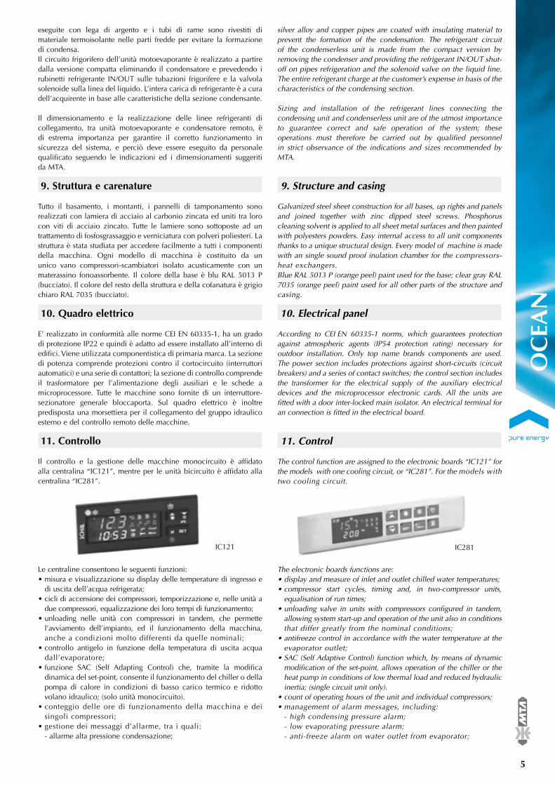
11. Controllo
Il controllo e la gestione delle macchine monocircuito è affidato alla centralina “IC121”, mentre per le unità bicircuito è affidato alla centralina “IC281”.
Le centraline consentono le seguenti funzioni:• misura e visualizzazione su display delle temperature di ingresso e
di uscita dell’acqua refrigerata;• cicli di accensione dei compressori, temporizzazione e, nelle unità a
due compressori, equalizzazione dei loro tempi di funzionamento;• unloading nelle unità con compressori in tandem, che permette
l’avviamento dell’impianto, ed il funzionamento della macchina, anche a condizioni molto differenti da quelle nominali;
• controllo antigelo in funzione della temperatura di uscita acqua dall’evaporatore;
• funzione SAC (Self Adapting Control) che, tramite la modifica dinamica del set-point, consente il funzionamento del chiller o della pompa di calore in condizioni di basso carico termico e ridotto volano idraulico; (solo unità monocircuito).
• conteggio delle ore di funzionamento della macchina e dei singoli compressori;
• gestione dei messaggi d’allarme, tra i quali: - allarme alta pressione condensazione;
silver alloy and copper pipes are coated with insulating material to prevent the formation of the condensation. The refrigerant circuit of the condenserless unit is made from the compact version by removing the condenser and providing the refrigerant IN/OUT shut-off on pipes refrigeration and the solenoid valve on the liquid line. The entire refrigerant charge at the customer’s expense in basis of the characteristics of the condensing section.
Sizing and installation of the refrigerant lines connecting the condensing unit and condenserless unit are of the utmost importance to guarantee correct and safe operation of the system; these operations must therefore be carried out by qualified personnel in strict observance of the indications and sizes recommended by MTA.
9. Structure and casing
Galvanized steel sheet construction for all bases, up rights and panels and joined together with zinc dipped steel screws. Phosphorus cleaning solvent is applied to all sheet metal surfaces and then painted with polyesters powders. Easy internal access to all unit components thanks to a unique structural design. Every model of machine is made with an single sound proof inulation chamber for the compressors-heat exchangers.Blue RAL 5013 P (orange peel) paint used for the base; clear gray RAL 7035 (orange peel) paint used for all other parts of the structure and casing.
10. Electrical panel
According to CEI EN 60335-1 norms, which guarantees protection against atmospheric agents (IP54 protection rating) necessary for outdoor installation. Only top name brands components are used. The power section includes protections against short-circuits (circuit breakers) and a series of contact switches; the control section includes the transformer for the electrical supply of the auxiliary electrical devices and the microprocessor electronic cards. All the units are fitted with a door inter-locked main isolator. An electrical terminal for an connection is fitted in the electrical board.
11. Control
The control function are assigned to the electronic boards “IC121” for the models with one cooling circuit, or “IC281”. For the models with two cooling circuit.
The electronic boards functions are:• display and measure of inlet and outlet chilled water temperatures;• compressor start cycles, timing and, in two-compressor units,
equalisation of run times;• unloading valve in units with compressors configured in tandem,
allowing system start-up and operation of the unit also in conditions that differ greatly from the nominal conditions;
• antifreeze control in accordance with the water temperature at the evaporator outlet;
• SAC (Self Adaptive Control) function which, by means of dynamic modification of the set-point, allows operation of the chiller or the heat pump in conditions of low thermal load and reduced hydraulic inertia; (single circuit unit only).
• count of operating hours of the unit and individual compressors;• management of alarm messages, including: - high condensing pressure alarm; - low evaporating pressure alarm; - anti-freeze alarm on water outlet from evaporator;
OC
EAN
IC121 IC281

®
6
- allarme bassa pressione evaporazione; - allarme antigelo sull’acqua in uscita dall’evaporatore; - allarme per guasto compressore, ed eventuale pompa; - allarme per insufficiente passaggio acqua attraverso l’evaporatore; - allarme alta temperatura ingresso e uscita acqua.
E’ inoltre disponibile un contatto pulito per portare a distanza la segnalazione di un allarme generale.
12. Gruppo idraulico esterno (kit addizionale)
Per tutte le macchine è prevista l’installazione di un gruppo idraulico opzionale esterno, dotato di una propria carpenteria, costituito da una pompa di circolazione e un serbatoio di accumulo.Il gruppo idraulico può essere fornito nelle seguenti configurazioni:• con pompa standard (P0): avente una prevalenza disponibile
compresa fra i 5 e i 10 m. c.a.• con pompa ad alta prevalenza (P1): avente una prevalenza
disponibile compresa fra i 10 e i 15 m. c.a. (disponibile solo per i modelli con alimentazione elettrica trifase).
In entrambe le configurazioni il serbatoio è costituito da un cilindro in acciaio al carbonio rivestito esternamente da uno strato isolante anticondensa:• disposto verticalmente nei primi nove modelli (dal mod. 018 al
mod. 150);• disposto orizzontalmente nei restanti sette modelli (dal mod. 200
al mod. 600).
Ogni gruppo idraulico è equipaggiato con:• vaso di espansione;• valvola di sfiato automatico;• valvola di sicurezza;• rubinetto di drenaggio;• gruppo di caricamento automatico con manometro;• raccordi portagomma e tubo flessibile per il collegamento all'unità
secondo gli schemi riportati nel capitolo "Disegni d'ingombro".
13. Opzioni, kit ed esecuzioni speciali
Opzioni: (le opzioni devono essere specificate in fase d’ordine poichè installate in fabbrica).• resistenza carter compressori nella versione chiller solo freddo.
Kit (i kit sono accessori che vengono forniti come collo a parte, generalmente contemporaneamente all'unità, ed installati a cura del cliente. Possono essere forniti anche in un secondo momento in qualità di ricambi, kit di modifica, di completamento, ecc.):• valvola pressostatica per il controllo della condensazione (all’atto
dell’installazione nelle pompe di calore con inversione di ciclo lato acqua, accertarsi che la distanza tra la valvola pressostatica e la relativa presa di pressione sul condensatore sia tale da permettere la connessione del capillare);
• supporti antivibranti;• dispositivo phase monitor: relè di massima/minima tensione (±/-
10%), mancanza e controllo di sequenza delle fasi;• gruppo idraulico esterno: vd capitolo “gruppo idraulico esterno
(opzionale)”;• terminale utente remoto replicato, “VI610” e “VI820”, per la gestione
a distanza (fino a 150 m) delle unità rispettivamente monocircuito e bicircuito;
• supervisione XWEB300: l’XWEB300 rappresenta uno dei sistemi di monitoraggio, controllo
- compressor and possible pump alarm; - insufficient water flow through the evaporator; - high temperature alarm inlet/outlet water.
Are available, a free contact for a remote general alarm and another free contact for a remote switch ON-OFF of the machines.
12. External hydraulic group (additional kit)
For all machines is possible to install (option) an external hydronic kit, with an own structure and casing, made with an pump and an storage tank.Hydraulic group can be configured:• with standard pump (P0): have an available pressure from 5 to 10 m. c.a.• with high pressure pump (P1): have an available pressure from 10
to 15 m. c.a. (available only for the models with three-phase power supply).
For two configurations the storage tank is cylindrical and made of carbon steel, coated externally with a layer of anti-condensation insulation material:• vertical for the first nine models (from mod. 018 to mod. 150);• horizontal for the others seven models (from mod. 200 to mod.
600).
All hydraulic group comprises the following components:• expansion tank;• automatic relief valve;• safety valve;• drainage valve;• automatic filling kit with pressure gauge;• elbow hoze nozzle and flexible pipe for connecting to the unit
following the diagrams in the chapter "Overall dimensions".
13. Options, kits and special designs
Options: (the options must be specified at the time of the order because they are installed in the factory:• compressor cranckcase heaters in cooling-only chiller versions.
Kits (the kits are supplied separately, generally at the same time of the unit, and installed by the user. They can be supplied later as spare parts, modification kits, completion kits, etc.):• condensation pressostatic control valve (during the installation in
heat pumps with reversed cycle water side, be sure that the distance between the pressostatic valve and the position on the condenser where the pressure is measured is such to allow the capillary to be connected);
• anti-vibration supports;• phase monitor device: maximum/minimum voltage (+/- 10%) relay,
missing phase and phase sequence monitoring;• external hydraulic group: see chapter “external hydraulic group
(optional)”;• replicated remote user teminal “VI610” and “VI820” for remote
management (up to 150 m) of single-circuit and dual circuit units respectively;
• XWEB300 supervision kit; XWEB 300 is one of the most advanced monitoring, control and
VI610 VI820
OC
EAN

®
7
e supervisione più evoluti oggi presenti sul mercato ed utilizza le più moderne tecnologie applicabili al mondo “Internet”. Il kit è composto da:
- XWEB 300 server; - guida di collegamento rapida; - CD ROM con i manuali del software a corredo.
L’XWEB 300 è un piccolo server dotato di un sistema operativo μc-Linux in grado di trasmettere informazioni ad un PC-client dotato dei seguenti requisiti minimi: - Windows 98® o superiore; - Pentium II 300MHz con almeno 64 Mb-ram; - Java Virtual Machine; - Explorer 5.5 o superiore/ Netscape®.Il server legge, archivia e controlla tutte le informazioni provenienti dai controlli ad esso collegati e connessi alla linea seriale tramite protocollo di comunicazione Modbus-Rtu. Esso rende disponibili sia in connessione locale (tramite cavo seriale non fornito) che in connessione remota (in questo caso è necessario un modem da confermare a parte) nel formato di una pagina Web le seguenti funzioni:- gestione grafica e tabellare delle grandezze registrate durante il funzionamento;- monitoraggio, archiviazione e gestione degli allarmi;- gestione da remoto dei comandi (reset di allarmi o modifica parametri).
• supervisione XWEB300 + modem GSM: questo accessorio tramite un modem GSM permette l’invio di
messaggi SMS a telefoni cellulari per la segnalazione di allarmi e la ricezione di SMS da telefoni cellulari per la modifica di variabili. Il kit permette la connessione remota al server XWEB300 quando non sia disponibile una linea telefonica e comprende: l’XWEB300, il modem GSM, l’alimentatore, l’antenna con relativo cavo e il cavo di connessione modem GSM - XWEB300.
supervision systems currently available on the market, utilising cutting-edge technology compatible with the world of the Internet. Kit composition:
- XWEB 300 server: - quick connection guide; - CD ROM with manuals and software.
XWEB 300 is a small server with a μc-Linux operating system, capable of transmitting information to a client PC complying with the following minimum specification: - Windows 98® or higher; - Pentium II 300MHz with at least 64 Mb RAM; - Java Virtual Machine; - Explorer 5.5 or higher / Netscape®.The server reads, stores and checks all the information coming in from the controllers connected to it and connected to the serial line by means of the Modbus-Rtu communication protocol. The server provides access to the following functions both by means of a local connection (by means of a serial cable - not supplied) and using a remote connection (in this case a modem must be ordered separately) in Web page format: - graphic and table management of the parameters recorded during operation;- monitoring, filing and management of alarms;- remote management of commands (alarms reset or parameter editing).
• XWEB300 + GSM modem supervision kit: this accessory uses a GSM modem to send SMS text messages to
mobile phones for the notification of alarms, and to receive mobile network SMS text messages for modification of variables. The kit, which allows remote connection to the XWEB300 server when there is no telephone landline available, includes: XWEB300,GSM modem, power supply unit, antenna with relative cable and GSM modem - XWEB300 interface cable.
Connessione locale - Local connection
Connessione remota - Remote connection
Local PCStandard Browser
Portable Phone
RS485 network
Modem
Provider
Fax
Sms
PDA
Portable Phone
PDARS485 network
Local PC Standard Browser
modem GSM per supervisione XWEB300 GSM modem for XWEB300 supervision
OC
EAN

8
®
• supervisione RS 485 ModBus: questo accessorio consente il collegamento dell'unità con sistemi di
supervisione BMS con standard elettrico RS485 e protocollo di tipo MODBUS.
Esso è composto da un cavetto seriale e da una interfaccia seriale optoisolata necessaria a convertire il segnale TTL a 5 fili in uscita dai controlli elettronici IC121 e IC281 in un segnale RS485.
Esecuzioni speciali (sono alcune delle più comuni specialità richieste, normalmente non descritte dettagliatamente nei nostri cataloghi; la fattibilità di tali esecuzioni va studiata, confermata e quotata, caso per caso, con i nostri uffici commerciali precedentemente all'ordine):• refrigerante R22;• refrigerante R410A.
La selezione di un OCEAN viene eseguita tramite la tabella “Guida alla selezione” e tramite le Tabelle Dati relative a ciascuna singola macchina. Per una corretta selezione di un refrigeratore è necessario, inoltre:
1) Verificare che siano rispettati i limiti di funzionamento indicati nella tabella “Limiti di funzionamento”.
2) Verificare che la portata d’acqua da raffreddare o riscaldare sia compresa tra i valori di portata minima e massima indicati nella tabella “Dati generali” di ciascuna macchina; valori di portata troppo bassa comportano un flusso laminare e, di conseguenza, pericolo di ghiacciamento ed una cattiva regolazione; al contrario valori di portata troppo elevati comportano eccessive perdite di carico, e possibilità di rottura dei tubi dello scambiatore di calore acqua/refrigerante.
3) Prevedere l’aggiunta di glicole etilenico o di altri liquidi anticonge-lanti per utilizzi della macchina al di sotto di 5 °C di uscita dell’ac-qua e per impieghi al di sotto degli 0 °C di aria esterna. Consultare la tabella “Soluzioni di acqua e glicole etilenico” per determinare la quantità di glicole etilenico necessaria e per valutare la riduzione di resa frigorifera, l’aumento di potenza assorbita dai compressori e l’aumento delle perdite di carico agli scambiatori a causa della presenza del glicole etilenico.
4) Qualora la differenza di temperatura fra ingresso e uscita acqua agli scambiatori sia diversa da quella nominale correggere la selezione utilizzando le tabelle “Coefficienti correttivi T”.
• RS 485 ModBus supervision kit: this accessory allows the unit to be connected to BMS supervision
systems with RS485 electrical standard and MODBUS protocol. It is composed of a serial cable and an optically coupled serial interface, which is necessary in order to convert the 5-wire TTL signal (at the output of electronic controllers IC121 and IC281) into an RS485 signal.
Special designs (a selection of the most popular special features, nor-mally not described in detail in our catalogues; the feasibility of special designs must be assessed, confirmed, and priced on a case by case basis in communication with our sales offices before placing the order):• R22 refrigerant gas;• R410A refrigerant gas.
For OCEAN selecting use the table “Selection guide” and the table “Performance data” relative to each unit. For a correct chiller selection it is also necessary:
1) Observe the operational limits as indicated in the chart “Working limits”.
2) Verify that the cool water flow is between the minim and maximum values of water flow, which are described in the “General Data” table. A very low flow can cause laminar flow and thus danger of ice formation and poor unit control; a very high flow can cause great pressure drops and the possibility of tube failure inside the evaporator.
3) For working temperatures under 5 °C outlet water and 0 °C exter-nal air temperature it is necessary to add ethylene glycol or any other antifreeze liquids. Consult the chart “Solutions of water and glycol” to determine the necessary quantity of ethylene glycol, the reduction of cooling capacity, the increase of power absorbed by the compressors, the increase of evaporators pressure drop and the increase of exchangers pressure drop due to the presence of the ethylene glycol.
4) When the difference in temperature between exchangers water inlet and outlet is different from the nominal T, the selection must be corrected using the table “Corrective coefficients T”.
GUIDA ALLA SELEZIONE - SELECTION GUIDE
OC
EAN
interfaccia seriale optoisolata optically coupled interface

9
®
POTENZA FRIGORIFERA - COOLING CAPACITY (kW)Temperatura uscita acqua dal condensatore - Condenser outlet water temperature (°C) t max (*)
35 38 40 45 48 50 (°C)
OC 018 4,20 4,12 4,06 3,90 3,79 3,71 50OC 022 5,09 4,95 4,86 4,61 4,46 4,35 50OC 030 7,23 6,96 6,80 6,39 6,14 5,97 50OC 040 10,5 10,2 9,99 9,44 9,09 8,84 50OC 050 14,3 13,9 13,7 13,2 13,0 12,8 50OC 070 23,5 22,7 22,2 20,9 20,1 19,5 50OC 100 32,0 30,9 30,2 28,2 27,0 26,1 50OC 130 41,1 39,8 38,9 36,4 34,9 33,8 50OC 150 47,6 46,0 44,9 42,0 40,2 39,0 50OC 200 62,4 60,4 58,9 55,1 52,7 51,0 50OC 230 72,7 70,4 68,7 64,4 61,6 59,8 50OC 280 89,5 86,5 84,6 79,3 76,0 73,6 50OC 350 114 110 108 101 97,1 94,5 50OC 400 132 127 125 118 113 111 50OC 500 161 156 153 145 140 136 50OC 600 194 188 184 174 167 163 50
PRESTAZIONI UNITÀ SOLO FREDDO - PERFORMANCE DATA COOLING
(*): Temperatura massima uscita dal condensatore, riferita alla temperatura uscita acqua evaporatore di 7 °C. Per selezionare il modello di refrigeratore è necessario scegliere la colonna indicante la massima temperatura in uscita acqua al condensatore con cui la macchina dovrà lavorare e la riga con la resa frigorifera richiesta. Le rese indicate nella tabella sono riferite alle seguenti condizioni: temperatura ingresso / uscita acqua evaporatore 12 / 7 °C, T condensatore torre 5 °C, T condensatore pozzo 10 °C. Per condizioni diverse e per le altre caratteristiche della macchina consultare le tabelle interne relative al modello selezionato.
(*): Maximum outlet condenser temperature, refer to outlet evaporator water temperature condition at 7 °C. To select the chiller model you must choose the column that indicates the maximum condenser outlet water temperature and the line with the cooling capacity requested. The capacities shown in the table refer to the following conditions: evaporator inlet / outlet water temperature 12 / 7 °C , T condenser tower 5 °C, T condenser well water 10 °C. For other conditions and other unit specifications, consult the internal tables relative to the model selected.
Acqua di Torre - Tower water
POTENZA FRIGORIFERA - COOLING CAPACITY (kW)Temperatura uscita acqua dal condensatore - Condenser outlet water temperature (°C) t max (*)
30 32 34 36 38 40 (°C)
OC 018 4,29 4,28 4,25 4,20 4,16 4,10 50OC 022 5,29 5,27 5,19 5,10 5,00 4,91 50OC 030 7,71 7,62 7,43 7,25 7,08 6,90 50OC 040 11,1 10,9 10,7 10,5 10,3 10,1 50OC 050 15,1 14,8 14,5 14,3 14,0 13,8 50OC 070 24,8 24,5 24,0 23,5 23,0 22,5 50OC 100 34,1 33,4 32,8 32,1 31,4 30,6 50OC 130 43,8 42,9 42,1 41,2 40,3 39,4 50OC 150 50,7 49,7 48,8 47,7 46,7 45,6 50OC 200 66,7 65,4 64,0 62,7 61,3 59,8 50OC 230 77,4 76,0 74,5 73,0 71,4 69,8 50OC 280 95,4 93,6 91,7 89,8 87,9 85,8 50OC 350 121 119 116 114 112 109 50OC 400 140 137 135 132 130 127 50OC 500 169 167 164 161 158 155 50OC 600 205 202 198 194 191 187 50
Acqua di Pozzo - Well water
Conditioning your ambient, maximising your comfort.
OC
EAN

®
10
POTENZA FRIGORIFERA - COOLING CAPACITY (kW)Temperatura uscita acqua dal condensatore - Condenser outlet water temperature (°C) t max (*)
35 38 40 45 48 50 (°C)
HOC 018 4,11 4,04 3,99 3,83 3,72 3,64 50HOC 022 4,99 4,86 4,76 4,51 4,36 4,26 50HOC 030 7,06 6,80 6,62 6,21 5,96 5,80 50HOC 040 10,2 9,90 9,70 9,16 8,83 8,59 50HOC 050 14,2 13,8 13,6 13,1 12,8 12,7 50HOC 070 23,2 22,4 21,9 20,6 19,8 19,3 50HOC 100 31,5 30,5 29,8 27,9 26,7 25,9 50HOC 130 40,8 39,5 38,6 36,3 34,8 33,8 50HOC 150 47,4 45,8 44,7 42,0 40,2 39,0 50HOC 200 60,3 58,3 56,9 53,1 50,8 49,1 50HOC 230 71,3 69,0 67,3 63,0 60,3 58,4 50HOC 280 86,4 83,6 81,6 76,5 73,3 71,0 50HOC 350 111 107 105 98,4 94,6 91,8 50HOC 400 134 130 128 120 116 113 50HOC 500 159 154 151 143 138 135 50HOC 600 196 190 186 176 170 165 50
PRESTAZIONI POMPA DI CALORE - PERFORMANCE DATA HEAT PUMP
(*): Temperatura massima uscita dal condensatore, riferita alla temperatura uscita acqua evaporatore di 7 °C. Per selezionare il modello di refrigeratore è necessario scegliere la colonna indicante la massima temperatura in uscita acqua al condensatore con cui la macchina dovrà lavorare e la riga con la resa frigorifera richiesta. Le rese indicate nella tabella sono riferite alle seguenti condizioni: temperatura ingresso / uscita acqua evaporatore 12 / 7 °C, T condensatore torre 5 °C, T condensatore pozzo 10 °C. Per condizioni diverse e per le altre caratteristiche della macchina consultare le tabelle interne relative al modello selezionato.
(*): Maximum outlet condenser temperature, refer to outlet evaporator water temperature condition at 7 °C. To select the chiller model you must choose the column that indicates the maximum condenser outlet water temperature and the line with the cooling capacity requested. The capacities shown in the table refer to the following conditions: evaporator inlet / outlet water temperature 12 / 7 °C , T condenser tower 5 °C, T condenser well water 10 °C. For other conditions and other unit specifications, consult the internal tables relative to the model selected.
Raffreddamento (acqua di torre) - Cooling (tower water)
POTENZA FRIGORIFERA - COOLING CAPACITY (kW)Temperatura uscita acqua dal condensatore - Condenser outlet water temperature (°C) t max (*)
30 32 34 36 38 40 (°C)
HOC 018 4,18 4,18 4,16 4,12 4,07 4,02 50HOC 022 5,14 5,14 5,08 4,99 4,90 4,81 50HOC 030 7,43 7,43 7,27 7,08 6,90 6,73 50HOC 040 10,6 10,6 10,4 10,2 10,0 9,81 50HOC 050 14,8 14,7 14,5 14,2 13,9 13,7 50HOC 070 24,4 24,1 23,7 23,2 22,7 22,2 50HOC 100 33,2 32,9 32,3 31,6 30,9 30,2 50HOC 130 43,4 42,6 41,8 40,9 40,0 39,2 50HOC 150 49,9 49,5 48,5 47,5 46,5 45,4 50HOC 200 64,5 63,2 62,0 60,6 59,2 57,8 50HOC 230 76,0 74,5 73,1 71,5 70,0 68,4 50HOC 280 92,3 90,5 88,7 86,8 84,8 82,9 50HOC 350 118 116 113 111 109 106 50HOC 400 143 141 138 135 133 130 50HOC 500 167 165 162 160 157 154 50HOC 600 208 204 201 197 193 189 50
Raffreddamento (acqua di pozzo) - Cooling (well water)
OC
EAN

®
11
Conditioning your ambient, maximising your comfort.
POTENZA TERMICA - HEATING CAPACITY (kW)Temperatura uscita acqua dal l'evaporatore - Evaporator outlet water temperature (°C) t min (**)
2 5 7 10 13 15 (°C)
HOC 018 4,04 4,40 4,61 4,97 5,35 5,63 2HOC 022 4,60 5,13 5,43 5,91 6,42 6,78 2HOC 030 6,53 7,33 7,78 8,48 9,21 9,70 2HOC 040 9,72 10,7 11,3 12,1 13,0 13,6 2HOC 050 13,7 15,1 16,1 17,6 19,3 20,5 2HOC 070 21,0 23,3 24,7 26,8 29,2 30,8 2HOC 100 28,3 31,4 33,3 36,2 39,3 41,4 2HOC 130 37,1 41,3 43,7 47,5 51,6 54,4 2HOC 150 43,1 47,9 50,7 55,1 59,7 63,1 2HOC 200 56,4 62,1 65,6 71,3 77,3 81,5 2HOC 230 66,3 73,0 77,2 84,0 91,2 96,2 2HOC 280 80,8 89,0 94,1 102 111 117 2HOC 350 104 114 121 131 143 151 2
(***): Temperatura massima di condensazione, riferita alla temperatura uscita acqua evaporatore 7 °C. Per selezionare il modello di refrigeratore è necessario scegliere la colonna indicante la massima temperatura di condensazione con cui la macchina dovrà lavorare e la riga con la resa frigorifera richiesta. Le rese indicate nella tabella sono riferite alle seguenti condizioni: temperatura ingresso/uscita acqua evaporatore 12 / 7 °C. Per condizioni diverse e per le altre caratteristiche della macchina consultare le tabelle interne relative al modello selezionato.
(***): Maximum condenser temperature, refer to outlet evaporator water temperature condition 7 °C. To select the chiller model you must choose the column that indicates the maximum condenser temperature and the line with the cooling capacity requested. The capacities shown in the table refer to the following conditions: evaporator inlet/outlet water temperature 12 / 7 °C. For other conditions and other unit specifications, consult the internal tables relative to the model selected.
Riscaldamento (acqua di torre / pozzo) - Heating (tower / well water)
POTENZA FRIGORIFERA - COOLING CAPACITY (kW)Temperatura di condensazione Dew - Dew condensation temperature (°C) t max Dew (***)
35 40 45 50 55 (°C)
OC 018 / ME 4,32 4,23 4,10 3,94 3,75 64OC 022 / ME 5,36 5,14 4,90 4,64 4,38 64OC 030 / ME 7,88 7,38 6,92 6,49 6,06 64OC 040 / ME 11,2 10,7 10,2 9,65 9,05 64OC 050 / ME 15,3 14,6 14,0 13,4 13,0 64OC 070 / ME 25,2 24,0 22,8 21,5 20,0 64OC 100 / ME 34,7 33,0 31,2 29,2 27,1 64OC 130 / ME 44,7 42,6 40,3 37,9 35,2 64OC 150 / ME 51,9 49,4 46,7 43,8 40,7 64OC 200 / ME 67,8 64,5 60,9 57,0 52,9 64OC 230 / ME 78,6 74,9 70,8 66,4 61,7 64OC 280 / ME 96,9 92,3 87,2 81,9 76,1 64OC 350 / ME 123 118 111 105 98,0 64OC 400 / ME 142 136 129 121 114 64OC 500 / ME 172 165 158 150 141 64OC 600 / ME 210 201 191 181 170 64
PRESTAZIONI UNITÀ MOTOEVAPORANTE - PERFORMANCE DATA CONDENSERLESS
(**): Temperatura minima uscita dall’evaporatore, riferita alla temperatura uscita acqua condensatore di 45 °C. Per selezionare il modello di pompa di calore è necessario scegliere la colonna indicante la minima temperatura in uscita acqua dall’evaporatore con cui la macchina dovrà lavorare e la riga con la resa termica richiesta. Le rese indicate nella tabella sono riferite alle seguenti condizioni: temperatura ingresso / uscita acqua condensatore 40 / 45 °C, T evaporatore 5 °C. Per condizioni diverse e per le altre caratteristiche della macchina consultare le tabelle interne relative al modello selezionato.
(**): Minimum outlet evaporator temperature, refer to outlet condenser water temperature condition at 45 °C. To select the heat pump model you must choose the column that indicates the minimum evaporator outlet water temperature and the line with the heating capacity requested. The capacities shown in the table refer to the following conditions: condenser inlet / outlet water temperature 40 / 45 °C, T evaporator 5 °C. For other conditions and other unit specifications, consult the internal tables relative to the model selected. O
CEA
N

12
®
PRESTAZIONI E DATI TECNICI - PERFORMANCE AND TECHNICAL DATA
DATI GENERALI - GENERAL DATA
(1) Calcolato secondo le condizioni EECCAC. Calculated according to EECCAC conditions.(2) Calcolato secondo lo Standard ARI 550/590-2003. Calculated according to ARI Standard 550/590-2003.Le versioni motoevaporanti ( OC /ME ) vengono fornite senza condensatori. Condenserless versions ( OC /ME ) are supplied without condensers.
Bande d'ottava - Octave bands (Hz) Potenza Pressione63 125 250 500 1000 2000 4000 8000 Power Pressure
Livello di potenza sonora - Sound power level dB(A) dB (A) dB (A)10m
35,7 51,0 54,2 49,0 50,7 45,9 37,4 30,8 58,1 30,1
LIVELLI SONORI - SOUND LEVELS
Distanza (1)
KdBDistance (1)
L (m)1 153 105 6
10 0
OCEAN HOCEAN
Circuiti frigoriferi Cooling circuits N° 1Compressori Compressors N° 1Gradini di parzializzazione Capacity control % 0 - 100ESEER (1) ESEER (1) - 3,74 3,69IPLV (2) IPLV (2) - 3,66 3,66Alimentazione elettrica Electrical power supplyPotenza Power V / Ph / Hz 230 ± 10 % / 1 / 50Ausiliari Auxiliary V / Ph / Hz 24 ± 10 % / 1 / 50Evaporatore EvaporatorEvaporatore Evaporator N° 1 1Portata min evaporatore Min evaporator fl ow rate m3/h 0,300 0,300Portata max evaporatore Max evaporator fl ow rate m3/h 1,60 1,60Volume d’acqua evaporatore Evaporator water volume I 0,22 0,22Condensatore CondenserCondensatore Condenser N° 1 1Portata min condensatore torre/pozzo Min condenser tower/well fl ow rate m3/h 0,250 0,300Portata max condensatore torre/pozzo Max condenser tower/well fl ow rate m3/h 1,20 1,60Volume d’acqua condensatore torre/pozzo Water volume condenser tower/well water I 0,17 0,22Dimensioni e pesi in esercizio Dimensions and installed weightProfondità Lenght mm 310 310Larghezza Width mm 520 520Altezza Height mm 800 800Peso (versione base) Weight (base version) kg 48 53Peso (versione motoevaporante) Weight (condenserless version) kg 47 -Dimensioni e pesi in esercizio gruppo idraulico esterno
Dimensions and installed weight external hydraulic group
Profondità Lenght mm 310Larghezza Width mm 520Altezza Height mm 800Peso Weight kg 123
FLI = potenza massima assorbita nelle condizioni limite di funzionamento; max power absorbed in the working limits condition; FLA = corrente massima assorbita nelle condizioni limite di funzionamento; max current absorbed in the working limits condition; ICF = corrente di spunto alla partenza dell’ultimo compressore nelle condizioni limite di funzionamento; start-up current at the start of the last compressor in the working limits condition.
ASSORBIMENTI ELETTRICI - ELECTRICAL DATA
Totale senza pompa - Total without pump Totale con pompa P0 - Total with P0 pump Totale con pompa P1 - Total with P1 pump
FLI (kW) FLA (A) ICF (A) FLI (kW) FLA (A) ICF (A) FLI (kW) FLA (A) ICF (A)1,67 7,70 34,0 2,07 9,72 36,0 - - -
Potenza sonora: determinata sulla base di misure effettuate in accordo alla normativa ISO 3744. Pressione sonora a 10 m: valore medio ricavato in campo libero su piano riflettente ad una distanza di 10 m dal lato esterno quadro elettrico della macchina e a 1.6 m di altezza rispetto alla base di appoggio dell’unità. Valori con tolleranza ± 2 dB. I livelli sonori si riferiscono al funzionamento dell’unità a pieno carico in condizioni nominali. (1) Per calcolare il livello di pressione sonora ad una distanza diversa impiegare la formula: dB(A)L=dB(A)10m+Kdb.
Sound power: determined on the basis of measurements taken in accordance with the standard ISO 3744. Sound pressure at 10 m: average value obtained in free field on a reflective surface at a distance of 10 m from the external side of the electrical panel of machine and at a height of 1.6 m from the unit support base. Values with tolerance +/- 2 dB. The sound levels refer to operation of the unit under full load in nominal conditions. (1) To calculate a different distance of the sound pressure level, use the formula: dB(A)L=dB(A)10m+Kdb.
GRUPPO IDRAULICO ESTERNO (KIT ADDIZIONALE) - EXTERNAL HYDRAULIC GROUP (ADDITIONAL KIT)
abbinato a linked with
OCEANabbinato a linked with
HOCEAN
Portata acqua Water fl ow rate m3/h 0,530 0,65 0,829 1,02 1,13 0,530 0,65 0,829 1,02 1,13Prevalenza disponibile P0 (1) Available head pressure P0 (1) kPa 95 87 74 58 47 95 87 74 58 47Prevalenza disponibile P1 (1) Available head pressure P1 (1) kPa - - - - - - - - - -Potenza nominale pompa P0 Nominal power pump P0 kW 0,4 0,4Potenza nominale pompa P1 Nominal power pump P1 kW - -Volume serbatoio Tank volume I 40 40Volume vaso di espansione Expansion tank volume n° x I 1 x 5 1 x 5
(1) Prevalenza disponibile agli attacchi utenza (al netto delle perdite di carico nel chiller e nel gruppo idraulico esterno). Available head pressure at unit hydraulic connections (net value which has taken into account pressure drops within chiller and its hydraulic group).P0 = pompa standard; standard pump.P1 = pompa alta prevalenza; high pressure pump.
OC
EAN
018

®
13
Conditioning your ambient, maximising your comfort.
PRESTAZIONI UNITÀ SOLO FREDDO - PERFORMANCE DATA CHILLER UNIT
Temperatura uscita acqua al condensatore - Outlet water condenser temperature (°C)t max (*)
(°C)35 38 40 45 48 50
Pf Pa Fw Pf Pa Fw Pf Pa Fw Pf Pa Fw Pf Pa Fw Pf Pa Fwtu (°C) (kW) (kW) (m3/h) (kW) (kW) (m3/h) (kW) (kW) (m3/h) (kW) (kW) (m3/h) (kW) (kW) (m3/h) (kW) (kW) (m3/h)
5 3,96 1,08 0,681 3,88 1,13 0,668 3,82 1,16 0,658 3,66 1,25 0,631 3,55 1,31 0,612 3,48 1,35 0,598 506 4,08 1,08 0,702 4,00 1,13 0,689 3,94 1,17 0,679 3,78 1,26 0,651 3,67 1,32 0,632 3,59 1,36 0,618 507 4,20 1,09 0,723 4,12 1,14 0,710 4,06 1,18 0,700 3,90 1,27 0,672 3,79 1,33 0,653 3,71 1,37 0,639 508 4,32 1,10 0,745 4,25 1,15 0,731 4,19 1,19 0,721 4,03 1,28 0,693 3,91 1,33 0,674 3,84 1,37 0,661 509 4,45 1,11 0,767 4,37 1,16 0,754 4,32 1,19 0,744 4,15 1,28 0,716 4,04 1,34 0,696 3,97 1,38 0,683 50
10 4,59 1,12 0,790 4,51 1,17 0,777 4,45 1,20 0,767 4,29 1,29 0,739 4,17 1,35 0,719 4,10 1,39 0,706 50
OC
Acqua di torre - Tower water
Acqua di pozzo - Well waterTemperatura uscita acqua al condensatore - Outlet water condenser temperature (°C)
t max (*)(°C)
30 32 34 36 38 40Pf Pa Fw Pf Pa Fw Pf Pa Fw Pf Pa Fw Pf Pa Fw Pf Pa Fw
tu (°C) (kW) (kW) (m3/h) (kW) (kW) (m3/h) (kW) (kW) (m3/h) (kW) (kW) (m3/h) (kW) (kW) (m3/h) (kW) (kW) (m3/h)
5 4,05 1,01 0,697 4,04 1,01 0,696 4,01 1,04 0,690 3,96 1,07 0,682 3,91 1,11 0,674 3,86 1,14 0,664 506 4,17 1,01 0,718 4,16 1,02 0,717 4,12 1,05 0,710 4,08 1,08 0,703 4,03 1,11 0,694 3,98 1,15 0,685 507 4,29 1,02 0,740 4,28 1,03 0,738 4,25 1,06 0,731 4,20 1,09 0,724 4,16 1,12 0,716 4,10 1,15 0,706 508 4,42 1,02 0,762 4,41 1,03 0,760 4,37 1,06 0,753 4,33 1,10 0,746 4,28 1,13 0,737 4,23 1,16 0,728 509 4,55 1,03 0,785 4,54 1,04 0,783 4,50 1,07 0,776 4,46 1,10 0,768 4,41 1,14 0,760 4,35 1,17 0,750 50
10 4,69 1,04 0,808 4,68 1,05 0,806 4,64 1,08 0,799 4,59 1,11 0,791 4,54 1,14 0,783 4,49 1,18 0,773 50
OC
PRESTAZIONI UNITÀ POMPA DI CALORE - PERFORMANCE DATA HEAT PUMP UNIT
Temperatura uscita acqua al condensatore - Outlet water condenser temperature (°C)t max (*)
(°C)35 38 40 45 48 50
Pf Pa Fw Pf Pa Fw Pf Pa Fw Pf Pa Fw Pf Pa Fw Pf Pa Fwtu (°C) (kW) (kW) (m3/h) (kW) (kW) (m3/h) (kW) (kW) (m3/h) (kW) (kW) (m3/h) (kW) (kW) (m3/h) (kW) (kW) (m3/h)
5 3,88 1,05 0,668 3,81 1,10 0,655 3,75 1,14 0,646 3,60 1,23 0,619 3,49 1,28 0,601 3,41 1,32 0,588 506 3,99 1,06 0,688 3,92 1,11 0,675 3,87 1,14 0,666 3,71 1,23 0,639 3,60 1,29 0,621 3,53 1,33 0,607 507 4,11 1,07 0,708 4,04 1,12 0,696 3,99 1,15 0,687 3,83 1,24 0,659 3,72 1,30 0,641 3,64 1,34 0,628 508 4,24 1,07 0,730 4,16 1,12 0,717 4,11 1,16 0,708 3,95 1,25 0,680 3,84 1,31 0,662 3,77 1,34 0,649 509 4,36 1,08 0,751 4,29 1,13 0,739 4,23 1,17 0,729 4,08 1,26 0,703 3,97 1,31 0,684 3,89 1,35 0,671 50
10 4,49 1,09 0,774 4,42 1,14 0,761 4,36 1,17 0,752 4,21 1,26 0,725 4,10 1,32 0,706 4,02 1,36 0,693 50
HOC
Raffreddamento (acqua di torre) - Cooling (tower water)
Raffreddamento (acqua di pozzo) - Cooling (well water)
Riscaldamento (acqua di torre / pozzo) - Heating (tower / well water)
PRESTAZIONI UNITÀ MOTOEVAPORANTE - PERFORMANCE DATA CONDENSERLESS UNIT
Temperatura uscita acqua al condensatore - Outlet water condenser temperature (°C)t max (*)
(°C)30 32 34 36 38 40
Pf Pa Fw Pf Pa Fw Pf Pa Fw Pf Pa Fw Pf Pa Fw Pf Pa Fwtu (°C) (kW) (kW) (m3/h) (kW) (kW) (m3/h) (kW) (kW) (m3/h) (kW) (kW) (m3/h) (kW) (kW) (m3/h) (kW) (kW) (m3/h)
5 3,95 1,00 0,679 3,95 1,00 0,679 3,92 1,02 0,675 3,88 1,05 0,668 3,83 1,08 0,660 3,78 1,12 0,651 506 4,06 1,01 0,700 4,06 1,01 0,700 4,04 1,03 0,695 4,00 1,06 0,688 3,95 1,09 0,680 3,90 1,13 0,671 507 4,18 1,01 0,720 4,18 1,01 0,720 4,16 1,03 0,716 4,12 1,07 0,709 4,07 1,10 0,701 4,02 1,13 0,692 508 4,31 1,02 0,742 4,31 1,02 0,742 4,28 1,04 0,737 4,24 1,07 0,730 4,19 1,11 0,722 4,14 1,14 0,713 509 4,44 1,03 0,764 4,44 1,03 0,764 4,41 1,05 0,759 4,37 1,08 0,752 4,32 1,11 0,744 4,27 1,15 0,735 50
10 4,57 1,03 0,787 4,57 1,03 0,787 4,54 1,06 0,782 4,50 1,09 0,775 4,45 1,12 0,767 4,40 1,15 0,758 50
HOC
Temperatura uscita acqua al condensatore - Outlet water condenser temperature (°C)t min (**)
(°C)2 5 7 10 13 15
Ph Pa Fw Ph Pa Fw Ph Pa Fw Ph Pa Fw Ph Pa Fw Ph Pa Fwtc (°C) (kW) (kW) (m3/h) (kW) (kW) (m3/h) (kW) (kW) (m3/h) (kW) (kW) (m3/h) (kW) (kW) (m3/h) (kW) (kW) (m3/h)
35 4,16 1,04 0,72 4,52 1,07 0,78 4,74 1,09 0,82 5,09 1,11 0,88 5,48 1,14 0,95 5,76 1,15 1,00 238 4,13 1,09 0,72 4,49 1,13 0,78 4,71 1,14 0,81 5,06 1,17 0,88 5,45 1,19 0,95 5,73 1,21 0,99 240 4,11 1,13 0,71 4,47 1,16 0,78 4,69 1,18 0,81 5,04 1,20 0,87 5,43 1,23 0,94 5,70 1,24 0,99 245 4,04 1,22 0,70 4,40 1,25 0,76 4,61 1,27 0,79 4,97 1,29 0,86 5,35 1,32 0,92 5,63 1,34 0,98 250 3,96 1,32 0,69 4,31 1,35 0,74 4,52 1,37 0,78 4,88 1,39 0,85 5,26 1,42 0,91 5,54 1,44 0,96 2
HOC
Temperatura uscita acqua al condensatore - Outlet water condenser temperature (°C) t max (*)Dew (°C)
35 40 45 50 55Pf Pa Fw Pf Pa Fw Pf Pa Fw Pf Pa Fw Pf Pa Fw
tu (°C) (kW) (kW) (m3/h) (kW) (kW) (m3/h) (kW) (kW) (m3/h) (kW) (kW) (m3/h) (kW) (kW) (m3/h)
5 4,08 0,981 0,702 3,99 1,06 0,686 3,86 1,14 0,664 3,69 1,23 0,636 3,50 1,33 0,603 646 4,20 0,987 0,723 4,11 1,06 0,707 3,98 1,15 0,685 3,81 1,24 0,657 3,62 1,34 0,624 647 4,32 0,994 0,744 4,23 1,07 0,728 4,10 1,15 0,706 3,94 1,25 0,678 3,75 1,35 0,645 648 4,45 1,00 0,766 4,36 1,08 0,750 4,23 1,16 0,728 4,07 1,25 0,700 3,88 1,35 0,668 649 4,58 1,01 0,789 4,49 1,08 0,773 4,36 1,17 0,751 4,20 1,26 0,723 4,01 1,36 0,690 64
10 4,72 1,01 0,813 4,62 1,09 0,797 4,50 1,17 0,775 4,33 1,27 0,747 4,14 1,37 0,714 64
OC / ME
tu: temperatura acqua uscita evaporatore, evaporator outlet water temperature; tc: temperatura acqua uscita condensatore, condensator outlet water temperature; Pf: potenza frigorifera, cooling capacity; Pa: potenza assorbita dai compressori, power absorbed by the compressors; Ph: potenza termica, heating capacity; Fw: portata d’acqua, water flow rate. I valori nominali sono riferiti alle seguenti condizioni: T evaporatore 5 °C, T condensatore torre (in modalità chiller) 5 °C, T condensatore pozzo (in modalità chiller) 10 °C, T condensatore (in modalità pompa di calore) 5 °C, T evaporatore (in modalità pompa di calore 5 °C). Per la determinazione delle prestazioni con T tra ingresso e uscita acqua dagli scambiatori diversa da quella nominale, utilizzare le tabelle “Coefficienti correttivi T”. È permessa l’interpolazione dei valori ma non la loro estrapolazione. (*): Temperatura massima al condensatore. Se la temperatura al condensatore è superiore a “t max” il refrigeratore non si blocca ma interviene il sistema “unloading” di parzializzazione (solo per i modelli dal 200 al 350). (**): Temperatura minima all’evaporatore. Se la temperatura all’evaporatore è inferiore a “t min” la pompa di calore non si blocca ma interviene il sistema “unloading” di parzializzazione (solo per i modelli dal 200 al 350). The nominal values are refered to: T evaporator 5 °C, T condenser tower water (chiller mode) 5 °C, T condenser well water (chiller mode) 10 °C, T condenser (heat pump mode) 5 °C, T evaporator (heat pump mode) 5 °C. To calculate performances at differing water inlet/outlet T levels, refer to the “ T correction factors” table. Interpolation is allowed, extrapolation is not permitted. (*): Maximum outlet water temperature in the condenser. When the condenser temperature is higher than the “t max” the chiller doesn’t stop but the “unloading” system capacity control is activated (only for the models from 200 to 350). (**): Min. evaporator temperature. When the evaporator temperature is lower than the “t min” the heat pump doesn’t stop but the “unloading” system capacity control is activated (only for the models from 200 to 350).
OC
EAN
018

14
®
OC
EAN
022
DATI GENERALI - GENERAL DATA
(1) Calcolato secondo le condizioni EECCAC. Calculated according to EECCAC conditions.(2) Calcolato secondo lo Standard ARI 550/590-2003. Calculated according to ARI Standard 550/590-2003.Le versioni motoevaporanti ( OC /ME ) vengono fornite senza condensatori. Condenserless versions ( OC /ME ) are supplied without condensers.
Bande d'ottava - Octave bands (Hz) Potenza Pressione63 125 250 500 1000 2000 4000 8000 Power Pressure
Livello di potenza sonora - Sound power level dB(A) dB (A) dB (A)10m
35,9 51,3 54,5 49,4 51,3 46,5 38,0 31,5 58,4 30,5
LIVELLI SONORI - SOUND LEVELS
Distanza (1)
KdBDistance (1)
L (m)1 153 105 6
10 0
OCEAN HOCEAN
Circuiti frigoriferi Cooling circuits N° 1Compressori Compressors N° 1Gradini di parzializzazione Capacity control % 0 - 100ESEER (1) ESEER (1) - 4,06 4,00IPLV (2) IPLV (2) - 3,90 3,93Alimentazione elettrica Electrical power supplyPotenza Power V / Ph / Hz 230 ± 10 % / 1 / 50Ausiliari Auxiliary V / Ph / Hz 24 ± 10 % / 1 / 50Evaporatore EvaporatorEvaporatore Evaporator N° 1 1Portata min evaporatore Min evaporator fl ow rate m3/h 0,370 0,370Portata max evaporatore Max evaporator fl ow rate m3/h 2,10 2,10Volume d’acqua evaporatore Evaporator water volume I 0,26 0,26Condensatore CondenserCondensatore Condenser N° 1 1Portata min condensatore torre/pozzo Min condenser tower/well fl ow rate m3/h 0,300 0,370Portata max condensatore torre/pozzo Max condenser tower/well fl ow rate m3/h 1,60 2,10Volume d’acqua condensatore torre/pozzo Water volume condenser tower/well water I 0,22 0,26Dimensioni e pesi in esercizio Dimensions and installed weightProfondità Lenght mm 310 310Larghezza Width mm 520 520Altezza Height mm 800 800Peso (versione base) Weight (base version) kg 52 57Peso (versione motoevaporante) Weight (condenserless version) kg 51 -Dimensioni e pesi in esercizio gruppo idraulico esterno
Dimensions and installed weight external hydraulic group
Profondità Lenght mm 310Larghezza Width mm 520Altezza Height mm 800Peso Weight kg 123
FLI = potenza massima assorbita nelle condizioni limite di funzionamento; max power absorbed in the working limits condition; FLA = corrente massima assorbita nelle condizioni limite di funzionamento; max current absorbed in the working limits condition; ICF = corrente di spunto alla partenza dell’ultimo compressore nelle condizioni limite di funzionamento; start-up current at the start of the last compressor in the working limits condition.
ASSORBIMENTI ELETTRICI - ELECTRICAL DATA
Totale senza pompa - Total without pump Totale con pompa P0 - Total with P0 pump Totale con pompa P1 - Total with P1 pump
FLI (kW) FLA (A) ICF (A) FLI (kW) FLA (A) ICF (A) FLI (kW) FLA (A) ICF (A)2,16 10,5 37,0 2,56 12,0 39,0 - - -
Potenza sonora: determinata sulla base di misure effettuate in accordo alla normativa ISO 3744. Pressione sonora a 10 m: valore medio ricavato in campo libero su piano riflettente ad una distanza di 10 m dal lato esterno quadro elettrico della macchina e a 1.6 m di altezza rispetto alla base di appoggio dell’unità. Valori con tolleranza ± 2 dB. I livelli sonori si riferiscono al funzionamento dell’unità a pieno carico in condizioni nominali. (1) Per calcolare il livello di pressione sonora ad una distanza diversa impiegare la formula: dB(A)L=dB(A)10m+Kdb.
Sound power: determined on the basis of measurements taken in accordance with the standard ISO 3744. Sound pressure at 10 m: average value obtained in free field on a reflective surface at a distance of 10 m from the external side of the electrical panel of machine and at a height of 1.6 m from the unit support base. Values with tolerance +/- 2 dB. The sound levels refer to operation of the unit under full load in nominal conditions. (1) To calculate a different distance of the sound pressure level, use the formula: dB(A)L=dB(A)10m+Kdb.
GRUPPO IDRAULICO ESTERNO (KIT ADDIZIONALE) - EXTERNAL HYDRAULIC GROUP (ADDITIONAL KIT)
abbinato a linked with
OCEANabbinato a linked with
HOCEAN
Portata acqua Water fl ow rate m3/h 0,643 0,79 1,01 1,17 1,38 0,643 0,79 1,01 1,17 1,38Prevalenza disponibile P0 (1) Available head pressure P0 (1) kPa 93 85 71 59 41 93 85 71 59 41Prevalenza disponibile P1 (1) Available head pressure P1 (1) kPa - - - - - - - - - -Potenza nominale pompa P0 Nominal power pump P0 kW 0,4 0,4Potenza nominale pompa P1 Nominal power pump P1 kW - -Volume serbatoio Tank volume I 40 40Volume vaso di espansione Expansion tank volume n° x I 1 x 5 1 x 5
(1) Prevalenza disponibile agli attacchi utenza (al netto delle perdite di carico nel chiller e nel gruppo idraulico esterno). Available head pressure at unit hydraulic connections (net value which has taken into account pressure drops within chiller and its hydraulic group).P0 = pompa standard; standard pump.P1 = pompa alta prevalenza; high pressure pump.

15
®
OC
EAN
022
Conditioning your ambient, maximising your comfort.
PRESTAZIONI UNITÀ SOLO FREDDO - PERFORMANCE DATA CHILLER UNIT
Temperatura uscita acqua al condensatore - Outlet water condenser temperature (°C)t max (*)
(°C)35 38 40 45 48 50
Pf Pa Fw Pf Pa Fw Pf Pa Fw Pf Pa Fw Pf Pa Fw Pf Pa Fwtu (°C) (kW) (kW) (m3/h) (kW) (kW) (m3/h) (kW) (kW) (m3/h) (kW) (kW) (m3/h) (kW) (kW) (m3/h) (kW) (kW) (m3/h)
5 4,77 1,22 0,822 4,64 1,30 0,798 4,54 1,35 0,782 4,29 1,49 0,739 4,14 1,59 0,712 4,04 1,66 0,695 506 4,93 1,23 0,849 4,79 1,31 0,825 4,70 1,36 0,809 4,45 1,50 0,766 4,30 1,60 0,740 4,19 1,67 0,722 507 5,09 1,24 0,876 4,95 1,31 0,853 4,86 1,37 0,836 4,61 1,51 0,793 4,46 1,61 0,767 4,35 1,68 0,749 508 5,25 1,25 0,905 5,12 1,32 0,881 5,02 1,38 0,864 4,77 1,52 0,821 4,62 1,62 0,796 4,51 1,69 0,778 509 5,42 1,26 0,933 5,28 1,33 0,910 5,19 1,38 0,893 4,94 1,53 0,850 4,78 1,63 0,824 4,68 1,70 0,806 50
10 5,59 1,27 0,963 5,45 1,34 0,940 5,36 1,39 0,923 5,11 1,54 0,881 4,95 1,64 0,854 4,85 1,71 0,836 50
OC
Acqua di torre - Tower water
Acqua di pozzo - Well waterTemperatura uscita acqua al condensatore - Outlet water condenser temperature (°C)
t max (*)(°C)
30 32 34 36 38 40Pf Pa Fw Pf Pa Fw Pf Pa Fw Pf Pa Fw Pf Pa Fw Pf Pa Fw
tu (°C) (kW) (kW) (m3/h) (kW) (kW) (m3/h) (kW) (kW) (m3/h) (kW) (kW) (m3/h) (kW) (kW) (m3/h) (kW) (kW) (m3/h)
5 4,96 1,14 0,854 4,96 1,14 0,853 4,87 1,18 0,839 4,78 1,22 0,824 4,70 1,26 0,808 4,60 1,31 0,792 506 5,12 1,14 0,882 5,11 1,15 0,881 5,03 1,19 0,866 4,94 1,23 0,850 4,85 1,28 0,834 4,75 1,33 0,818 507 5,29 1,15 0,910 5,27 1,16 0,908 5,19 1,20 0,893 5,10 1,24 0,878 5,00 1,29 0,862 4,91 1,33 0,846 508 5,45 1,16 0,940 5,44 1,17 0,937 5,35 1,20 0,922 5,26 1,25 0,906 5,17 1,29 0,891 5,08 1,34 0,875 509 5,63 1,16 0,969 5,61 1,17 0,966 5,52 1,21 0,951 5,43 1,25 0,936 5,34 1,30 0,920 5,24 1,35 0,903 50
10 5,80 1,17 1,00 5,78 1,18 0,995 5,69 1,22 0,981 5,60 1,26 0,966 5,51 1,31 0,950 5,42 1,36 0,933 50
OC
PRESTAZIONI UNITÀ POMPA DI CALORE - PERFORMANCE DATA HEAT PUMP UNIT
Temperatura uscita acqua al condensatore - Outlet water condenser temperature (°C)t max (*)
(°C)35 38 40 45 48 50
Pf Pa Fw Pf Pa Fw Pf Pa Fw Pf Pa Fw Pf Pa Fw Pf Pa Fwtu (°C) (kW) (kW) (m3/h) (kW) (kW) (m3/h) (kW) (kW) (m3/h) (kW) (kW) (m3/h) (kW) (kW) (m3/h) (kW) (kW) (m3/h)
5 4,68 1,19 0,806 4,54 1,26 0,782 4,45 1,31 0,766 4,20 1,45 0,723 4,05 1,55 0,698 3,95 1,61 0,680 506 4,83 1,20 0,832 4,70 1,27 0,808 4,60 1,32 0,792 4,36 1,46 0,750 4,20 1,56 0,724 4,10 1,63 0,706 507 4,99 1,21 0,859 4,86 1,28 0,836 4,76 1,33 0,820 4,51 1,47 0,777 4,36 1,57 0,751 4,26 1,63 0,734 508 5,15 1,22 0,888 5,01 1,29 0,864 4,92 1,34 0,847 4,67 1,48 0,805 4,52 1,58 0,779 4,42 1,64 0,761 509 5,32 1,23 0,916 5,18 1,30 0,892 5,08 1,35 0,876 4,84 1,49 0,833 4,69 1,59 0,807 4,58 1,65 0,789 50
10 5,48 1,24 0,945 5,34 1,31 0,921 5,25 1,36 0,905 5,01 1,50 0,863 4,85 1,59 0,836 4,75 1,66 0,818 50
HOC
Raffreddamento (acqua di torre) - Cooling (tower water)
Raffreddamento (acqua di pozzo) - Cooling (well water)
Riscaldamento (acqua di torre / pozzo) - Heating (tower / well water)
PRESTAZIONI UNITÀ MOTOEVAPORANTE - PERFORMANCE DATA CONDENSERLESS UNIT
Temperatura uscita acqua al condensatore - Outlet water condenser temperature (°C)t max (*)
(°C)30 32 34 36 38 40
Pf Pa Fw Pf Pa Fw Pf Pa Fw Pf Pa Fw Pf Pa Fw Pf Pa Fwtu (°C) (kW) (kW) (m3/h) (kW) (kW) (m3/h) (kW) (kW) (m3/h) (kW) (kW) (m3/h) (kW) (kW) (m3/h) (kW) (kW) (m3/h)
5 4,82 1,13 0,830 4,82 1,13 0,830 4,77 1,15 0,821 4,68 1,19 0,806 4,59 1,24 0,790 4,50 1,28 0,775 506 4,98 1,14 0,857 4,98 1,14 0,857 4,93 1,16 0,848 4,84 1,20 0,833 4,75 1,25 0,817 4,65 1,29 0,801 507 5,14 1,14 0,885 5,14 1,14 0,884 5,08 1,17 0,875 4,99 1,21 0,860 4,90 1,26 0,844 4,81 1,30 0,829 508 5,30 1,15 0,913 5,30 1,15 0,913 5,25 1,18 0,903 5,16 1,22 0,888 5,07 1,26 0,872 4,97 1,31 0,856 509 5,47 1,16 0,942 5,47 1,16 0,942 5,41 1,18 0,932 5,32 1,23 0,917 5,23 1,27 0,901 5,14 1,32 0,885 50
10 5,64 1,16 0,972 5,64 1,16 0,972 5,58 1,19 0,961 5,49 1,23 0,946 5,40 1,28 0,931 5,31 1,33 0,914 50
HOC
Temperatura uscita acqua al condensatore - Outlet water condenser temperature (°C)t min (**)
(°C)2 5 7 10 13 15
Ph Pa Fw Ph Pa Fw Ph Pa Fw Ph Pa Fw Ph Pa Fw Ph Pa Fwtc (°C) (kW) (kW) (m3/h) (kW) (kW) (m3/h) (kW) (kW) (m3/h) (kW) (kW) (m3/h) (kW) (kW) (m3/h) (kW) (kW) (m3/h)
35 4,78 1,15 0,83 5,31 1,22 0,91 5,62 1,24 0,97 6,09 1,28 1,05 6,60 1,31 1,14 6,96 1,33 1,21 238 4,72 1,22 0,82 5,25 1,29 0,91 5,56 1,32 0,96 6,04 1,36 1,05 6,54 1,39 1,13 6,90 1,41 1,20 240 4,68 1,28 0,80 5,21 1,35 0,90 5,52 1,38 0,96 6,00 1,42 1,04 6,50 1,45 1,12 6,86 1,47 1,19 245 4,60 1,44 0,80 5,13 1,50 0,89 5,43 1,53 0,94 5,91 1,57 1,03 6,42 1,61 1,12 6,78 1,62 1,18 250 4,53 1,61 0,79 5,06 1,67 0,88 5,36 1,71 0,93 5,84 1,75 1,01 6,35 1,78 1,11 6,70 1,80 1,17 2
HOC
Temperatura uscita acqua al condensatore - Outlet water condenser temperature (°C) t max (*)Dew (°C)
35 40 45 50 55Pf Pa Fw Pf Pa Fw Pf Pa Fw Pf Pa Fw Pf Pa Fw
tu (°C) (kW) (kW) (m3/h) (kW) (kW) (m3/h) (kW) (kW) (m3/h) (kW) (kW) (m3/h) (kW) (kW) (m3/h)
5 5,03 1,11 0,866 4,82 1,20 0,829 4,58 1,33 0,788 4,32 1,48 0,744 4,06 1,65 0,698 646 5,19 1,11 0,894 4,98 1,21 0,857 4,74 1,34 0,815 4,48 1,48 0,771 4,22 1,65 0,726 647 5,36 1,12 0,922 5,14 1,22 0,885 4,90 1,34 0,844 4,64 1,49 0,800 4,38 1,66 0,754 648 5,52 1,13 0,951 5,31 1,23 0,914 5,07 1,35 0,873 4,81 1,50 0,829 4,55 1,67 0,783 649 5,70 1,13 0,981 5,48 1,23 0,944 5,24 1,36 0,903 4,98 1,50 0,859 4,72 1,67 0,813 64
10 5,87 1,14 1,01 5,65 1,24 0,974 5,41 1,36 0,933 5,16 1,51 0,889 4,89 1,68 0,843 64
OC / ME
tu: temperatura acqua uscita evaporatore, evaporator outlet water temperature; tc: temperatura acqua uscita condensatore, condensator outlet water temperature; Pf: potenza frigorifera, cooling capacity; Pa: potenza assorbita dai compressori, power absorbed by the compressors; Ph: potenza termica, heating capacity; Fw: portata d’acqua, water flow rate. I valori nominali sono riferiti alle seguenti condizioni: T evaporatore 5 °C, T condensatore torre (in modalità chiller) 5 °C, T condensatore pozzo (in modalità chiller) 10 °C, T condensatore (in modalità pompa di calore) 5 °C, T evaporatore (in modalità pompa di calore 5 °C). Per la determinazione delle prestazioni con T tra ingresso e uscita acqua dagli scambiatori diversa da quella nominale, utilizzare le tabelle “Coefficienti correttivi T”. È permessa l’interpolazione dei valori ma non la loro estrapolazione. (*): Temperatura massima al condensatore. Se la temperatura al condensatore è superiore a “t max” il refrigeratore non si blocca ma interviene il sistema “unloading” di parzializzazione (solo per i modelli dal 200 al 350). (**): Temperatura minima all’evaporatore. Se la temperatura all’evaporatore è inferiore a “t min” la pompa di calore non si blocca ma interviene il sistema “unloading” di parzializzazione (solo per i modelli dal 200 al 350). The nominal values are refered to: T evaporator 5 °C, T condenser tower water (chiller mode) 5 °C, T condenser well water (chiller mode) 10 °C, T condenser (heat pump mode) 5 °C, T evaporator (heat pump mode) 5 °C. To calculate performances at differing water inlet/outlet T levels, refer to the “ T correction factors” table. Interpolation is allowed, extrapolation is not permitted. (*): Maximum outlet water temperature in the condenser. When the condenser temperature is higher than the “t max” the chiller doesn’t stop but the “unloading” system capacity control is activated (only for the models from 200 to 350). (**): Min. evaporator temperature. When the evaporator temperature is lower than the “t min” the heat pump doesn’t stop but the “unloading” system capacity control is activated (only for the models from 200 to 350).

16
®
OC
EAN
030
DATI GENERALI - GENERAL DATA
(1) Calcolato secondo le condizioni EECCAC. Calculated according to EECCAC conditions.(2) Calcolato secondo lo Standard ARI 550/590-2003. Calculated according to ARI Standard 550/590-2003.Le versioni motoevaporanti ( OC /ME ) vengono fornite senza condensatori. Condenserless versions ( OC /ME ) are supplied without condensers.
Bande d'ottava - Octave bands (Hz) Potenza Pressione63 125 250 500 1000 2000 4000 8000 Power Pressure
Livello di potenza sonora - Sound power level dB(A) dB (A) dB (A)10m
36,3 51,7 55,0 50,2 52,3 47,3 38,9 32,6 59,1 31,1
LIVELLI SONORI - SOUND LEVELS
Distanza (1)
KdBDistance (1)
L (m)1 153 105 6
10 0
OCEAN HOCEAN
Circuiti frigoriferi Cooling circuits N° 1Compressori Compressors N° 1Gradini di parzializzazione Capacity control % 0 - 100ESEER (1) ESEER (1) - 4,13 4,06IPLV (2) IPLV (2) - 3,83 3,87Alimentazione elettrica Electrical power supplyPotenza Power V / Ph / Hz 230 ± 10 % / 1 / 50Ausiliari Auxiliary V / Ph / Hz 24 ± 10 % / 1 / 50Evaporatore EvaporatorEvaporatore Evaporator N° 1 1Portata min evaporatore Min evaporator fl ow rate m3/h 0,500 0,500Portata max evaporatore Max evaporator fl ow rate m3/h 2,85 2,85Volume d’acqua evaporatore Evaporator water volume I 0,34 0,34Condensatore CondenserCondensatore Condenser N° 1 1Portata min condensatore torre/pozzo Min condenser tower/well fl ow rate m3/h 0,370 0,500Portata max condensatore torre/pozzo Max condenser tower/well fl ow rate m3/h 2,10 2,85Volume d’acqua condensatore torre/pozzo Water volume condenser tower/well water I 0,26 0,34Dimensioni e pesi in esercizio Dimensions and installed weightProfondità Lenght mm 310 310Larghezza Width mm 520 520Altezza Height mm 800 800Peso (versione base) Weight (base version) kg 58 63Peso (versione motoevaporante) Weight (condenserless version) kg 55 -Dimensioni e pesi in esercizio gruppo idraulico esterno
Dimensions and installed weight external hydraulic group
Profondità Lenght mm 310Larghezza Width mm 520Altezza Height mm 800Peso Weight kg 123
FLI = potenza massima assorbita nelle condizioni limite di funzionamento; max power absorbed in the working limits condition; FLA = corrente massima assorbita nelle condizioni limite di funzionamento; max current absorbed in the working limits condition; ICF = corrente di spunto alla partenza dell’ultimo compressore nelle condizioni limite di funzionamento; start-up current at the start of the last compressor in the working limits condition.
ASSORBIMENTI ELETTRICI - ELECTRICAL DATA
Totale senza pompa - Total without pump Totale con pompa P0 - Total with P0 pump Totale con pompa P1 - Total with P1 pump
FLI (kW) FLA (A) ICF (A) FLI (kW) FLA (A) ICF (A) FLI (kW) FLA (A) ICF (A)2,98 14,0 60,0 3,38 16,0 62,0 - - -
Potenza sonora: determinata sulla base di misure effettuate in accordo alla normativa ISO 3744. Pressione sonora a 10 m: valore medio ricavato in campo libero su piano riflettente ad una distanza di 10 m dal lato esterno quadro elettrico della macchina e a 1.6 m di altezza rispetto alla base di appoggio dell’unità. Valori con tolleranza ± 2 dB. I livelli sonori si riferiscono al funzionamento dell’unità a pieno carico in condizioni nominali. (1) Per calcolare il livello di pressione sonora ad una distanza diversa impiegare la formula: dB(A)L=dB(A)10m+Kdb.
Sound power: determined on the basis of measurements taken in accordance with the standard ISO 3744. Sound pressure at 10 m: average value obtained in free field on a reflective surface at a distance of 10 m from the external side of the electrical panel of machine and at a height of 1.6 m from the unit support base. Values with tolerance +/- 2 dB. The sound levels refer to operation of the unit under full load in nominal conditions. (1) To calculate a different distance of the sound pressure level, use the formula: dB(A)L=dB(A)10m+Kdb.
GRUPPO IDRAULICO ESTERNO (KIT ADDIZIONALE) - EXTERNAL HYDRAULIC GROUP (ADDITIONAL KIT)
abbinato a linked with
OCEANabbinato a linked with
HOCEAN
Portata acqua Water fl ow rate m3/h 0,904 1,11 1,24 1,46 1,72 0,904 1,11 1,24 1,46 1,72Prevalenza disponibile P0 (1) Available head pressure P0 (1) kPa 87 75 68 52 32 87 75 68 52 32Prevalenza disponibile P1 (1) Available head pressure P1 (1) kPa - - - - - - - - - -Potenza nominale pompa P0 Nominal power pump P0 kW 0,4 0,4Potenza nominale pompa P1 Nominal power pump P1 kW - -Volume serbatoio Tank volume I 40 40Volume vaso di espansione Expansion tank volume n° x I 1 x 5 1 x 5
(1) Prevalenza disponibile agli attacchi utenza (al netto delle perdite di carico nel chiller e nel gruppo idraulico esterno). Available head pressure at unit hydraulic connections (net value which has taken into account pressure drops within chiller and its hydraulic group).P0 = pompa standard; standard pump.P1 = pompa alta prevalenza; high pressure pump.

17
®
OC
EAN
030
Conditioning your ambient, maximising your comfort.
PRESTAZIONI UNITÀ SOLO FREDDO - PERFORMANCE DATA CHILLER UNIT
Temperatura uscita acqua al condensatore - Outlet water condenser temperature (°C)t max (*)
(°C)35 38 40 45 48 50
Pf Pa Fw Pf Pa Fw Pf Pa Fw Pf Pa Fw Pf Pa Fw Pf Pa Fwtu (°C) (kW) (kW) (m3/h) (kW) (kW) (m3/h) (kW) (kW) (m3/h) (kW) (kW) (m3/h) (kW) (kW) (m3/h) (kW) (kW) (m3/h)
5 6,78 1,78 1,17 6,52 1,89 1,12 6,35 1,96 1,09 5,94 2,17 1,02 5,69 2,30 0,980 5,53 2,38 0,951 506 7,00 1,79 1,21 6,74 1,90 1,16 6,57 1,98 1,13 6,16 2,18 1,06 5,91 2,31 1,02 5,75 2,40 0,989 507 7,23 1,80 1,24 6,96 1,92 1,20 6,80 1,99 1,17 6,39 2,19 1,10 6,14 2,32 1,06 5,97 2,41 1,03 508 7,46 1,81 1,28 7,19 1,93 1,24 7,03 2,00 1,21 6,62 2,21 1,14 6,37 2,33 1,10 6,20 2,42 1,07 509 7,69 1,83 1,33 7,43 1,94 1,28 7,26 2,02 1,25 6,85 2,22 1,18 6,60 2,35 1,14 6,43 2,43 1,11 50
10 7,93 1,84 1,37 7,66 1,95 1,32 7,50 2,03 1,29 7,08 2,23 1,22 6,84 2,36 1,18 6,67 2,44 1,15 50
OC
Acqua di torre - Tower water
Acqua di pozzo - Well waterTemperatura uscita acqua al condensatore - Outlet water condenser temperature (°C)
t max (*)(°C)
30 32 34 36 38 40Pf Pa Fw Pf Pa Fw Pf Pa Fw Pf Pa Fw Pf Pa Fw Pf Pa Fw
tu (°C) (kW) (kW) (m3/h) (kW) (kW) (m3/h) (kW) (kW) (m3/h) (kW) (kW) (m3/h) (kW) (kW) (m3/h) (kW) (kW) (m3/h)
5 7,25 1,61 1,25 7,17 1,63 1,23 6,99 1,70 1,20 6,80 1,77 1,17 6,63 1,84 1,14 6,46 1,92 1,11 506 7,47 1,62 1,29 7,39 1,64 1,27 7,21 1,71 1,24 7,02 1,78 1,21 6,85 1,85 1,18 6,68 1,93 1,15 507 7,71 1,63 1,33 7,62 1,66 1,31 7,43 1,72 1,28 7,25 1,79 1,25 7,08 1,87 1,22 6,90 1,94 1,19 508 7,95 1,64 1,37 7,86 1,67 1,35 7,66 1,73 1,32 7,48 1,81 1,29 7,31 1,88 1,26 7,13 1,96 1,23 509 8,29 1,61 1,43 8,09 1,68 1,39 7,90 1,75 1,36 7,72 1,81 1,33 7,54 1,89 1,30 7,37 1,97 1,27 50
10 8,44 1,65 1,45 8,34 1,68 1,44 8,14 1,75 1,40 7,96 1,83 1,37 7,78 1,90 1,34 7,60 1,98 1,31 50
OC
PRESTAZIONI UNITÀ POMPA DI CALORE - PERFORMANCE DATA HEAT PUMP UNIT
Temperatura uscita acqua al condensatore - Outlet water condenser temperature (°C)t max (*)
(°C)35 38 40 45 48 50
Pf Pa Fw Pf Pa Fw Pf Pa Fw Pf Pa Fw Pf Pa Fw Pf Pa Fwtu (°C) (kW) (kW) (m3/h) (kW) (kW) (m3/h) (kW) (kW) (m3/h) (kW) (kW) (m3/h) (kW) (kW) (m3/h) (kW) (kW) (m3/h)
5 6,62 1,72 1,14 6,36 1,83 1,09 6,19 1,91 1,06 5,77 2,11 0,993 5,53 2,23 0,951 5,36 2,32 0,922 506 6,84 1,74 1,18 6,58 1,84 1,13 6,40 1,92 1,10 5,99 2,12 1,03 5,74 2,25 0,989 5,58 2,33 0,960 507 7,06 1,75 1,22 6,80 1,86 1,17 6,62 1,93 1,14 6,21 2,13 1,07 5,96 2,26 1,03 5,80 2,34 1,00 508 7,29 1,76 1,26 7,02 1,87 1,21 6,86 1,94 1,18 6,44 2,15 1,11 6,20 2,27 1,07 6,03 2,36 1,04 509 7,52 1,77 1,30 7,25 1,88 1,25 7,09 1,96 1,22 6,67 2,16 1,15 6,42 2,28 1,11 6,26 2,37 1,08 50
10 7,75 1,78 1,34 7,49 1,89 1,29 7,32 1,97 1,26 6,91 2,17 1,19 6,66 2,30 1,15 6,49 2,38 1,12 50
HOC
Raffreddamento (acqua di torre) - Cooling (tower water)
Raffreddamento (acqua di pozzo) - Cooling (well water)
Riscaldamento (acqua di torre / pozzo) - Heating (tower / well water)
PRESTAZIONI UNITÀ MOTOEVAPORANTE - PERFORMANCE DATA CONDENSERLESS UNIT
Temperatura uscita acqua al condensatore - Outlet water condenser temperature (°C)t max (*)
(°C)30 32 34 36 38 40
Pf Pa Fw Pf Pa Fw Pf Pa Fw Pf Pa Fw Pf Pa Fw Pf Pa Fwtu (°C) (kW) (kW) (m3/h) (kW) (kW) (m3/h) (kW) (kW) (m3/h) (kW) (kW) (m3/h) (kW) (kW) (m3/h) (kW) (kW) (m3/h)
5 6,97 1,60 1,20 6,97 1,60 1,20 6,82 1,65 1,17 6,63 1,72 1,14 6,46 1,79 1,11 6,28 1,87 1,08 506 7,20 1,61 1,24 7,20 1,61 1,24 7,04 1,66 1,21 6,86 1,73 1,18 6,67 1,80 1,15 6,50 1,88 1,12 507 7,43 1,62 1,28 7,43 1,62 1,28 7,27 1,67 1,25 7,08 1,74 1,22 6,90 1,82 1,19 6,73 1,89 1,16 508 7,66 1,63 1,32 7,66 1,63 1,32 7,49 1,68 1,29 7,30 1,76 1,26 7,13 1,82 1,23 6,95 1,90 1,20 509 7,90 1,64 1,36 7,90 1,64 1,36 7,72 1,70 1,33 7,54 1,76 1,30 7,36 1,84 1,27 7,18 1,91 1,24 50
10 8,14 1,64 1,40 8,14 1,64 1,40 7,96 1,70 1,37 7,77 1,77 1,34 7,59 1,85 1,31 7,42 1,92 1,28 50
HOC
Temperatura uscita acqua al condensatore - Outlet water condenser temperature (°C)t min (**)
(°C)2 5 7 10 13 15
Ph Pa Fw Ph Pa Fw Ph Pa Fw Ph Pa Fw Ph Pa Fw Ph Pa Fwtc (°C) (kW) (kW) (m3/h) (kW) (kW) (m3/h) (kW) (kW) (m3/h) (kW) (kW) (m3/h) (kW) (kW) (m3/h) (kW) (kW) (m3/h)
35 6,91 1,71 1,20 7,73 1,79 1,34 8,18 1,83 1,42 8,87 1,87 1,54 9,60 1,92 1,66 10,1 1,94 1,75 238 6,78 1,83 1,16 7,60 1,91 1,32 8,05 1,94 1,40 8,74 1,99 1,52 9,47 2,03 1,64 9,98 2,06 1,73 240 6,70 1,91 1,16 7,52 1,99 1,31 7,97 2,03 1,37 8,66 2,07 1,49 9,39 2,12 1,63 9,90 2,14 1,72 245 6,53 2,12 1,13 7,33 2,20 1,27 7,78 2,23 1,35 8,48 2,28 1,47 9,21 2,32 1,58 9,70 2,35 1,67 250 6,35 2,34 1,10 7,15 2,41 1,23 7,59 2,44 1,32 8,29 2,49 1,44 9,01 2,53 1,57 9,51 2,56 1,66 2
HOC
Temperatura uscita acqua al condensatore - Outlet water condenser temperature (°C) t max (*)Dew (°C)
35 40 45 50 55Pf Pa Fw Pf Pa Fw Pf Pa Fw Pf Pa Fw Pf Pa Fw
tu (°C) (kW) (kW) (m3/h) (kW) (kW) (m3/h) (kW) (kW) (m3/h) (kW) (kW) (m3/h) (kW) (kW) (m3/h)
5 7,42 1,55 1,28 6,91 1,72 1,19 6,45 1,92 1,11 6,02 2,13 1,04 5,59 2,35 0,962 646 7,65 1,56 1,32 7,14 1,73 1,23 6,69 1,93 1,15 6,25 2,14 1,08 5,82 2,36 1,00 647 7,88 1,57 1,36 7,38 1,74 1,27 6,92 1,94 1,19 6,49 2,14 1,12 6,06 2,36 1,04 648 8,12 1,58 1,40 7,62 1,75 1,31 7,15 1,94 1,23 6,72 2,15 1,16 6,29 2,37 1,08 649 8,36 1,59 1,44 7,86 1,76 1,35 7,40 1,95 1,27 6,97 2,16 1,20 6,54 2,38 1,13 64
10 8,61 1,60 1,48 8,11 1,77 1,40 7,64 1,96 1,32 7,21 2,17 1,24 6,78 2,39 1,17 64
OC / ME
tu: temperatura acqua uscita evaporatore, evaporator outlet water temperature; tc: temperatura acqua uscita condensatore, condensator outlet water temperature; Pf: potenza frigorifera, cooling capacity; Pa: potenza assorbita dai compressori, power absorbed by the compressors; Ph: potenza termica, heating capacity; Fw: portata d’acqua, water flow rate. I valori nominali sono riferiti alle seguenti condizioni: T evaporatore 5 °C, T condensatore torre (in modalità chiller) 5 °C, T condensatore pozzo (in modalità chiller) 10 °C, T condensatore (in modalità pompa di calore) 5 °C, T evaporatore (in modalità pompa di calore 5 °C). Per la determinazione delle prestazioni con T tra ingresso e uscita acqua dagli scambiatori diversa da quella nominale, utilizzare le tabelle “Coefficienti correttivi T”. È permessa l’interpolazione dei valori ma non la loro estrapolazione. (*): Temperatura massima al condensatore. Se la temperatura al condensatore è superiore a “t max” il refrigeratore non si blocca ma interviene il sistema “unloading” di parzializzazione (solo per i modelli dal 200 al 350). (**): Temperatura minima all’evaporatore. Se la temperatura all’evaporatore è inferiore a “t min” la pompa di calore non si blocca ma interviene il sistema “unloading” di parzializzazione (solo per i modelli dal 200 al 350). The nominal values are refered to: T evaporator 5 °C, T condenser tower water (chiller mode) 5 °C, T condenser well water (chiller mode) 10 °C, T condenser (heat pump mode) 5 °C, T evaporator (heat pump mode) 5 °C. To calculate performances at differing water inlet/outlet T levels, refer to the “ T correction factors” table. Interpolation is allowed, extrapolation is not permitted. (*): Maximum outlet water temperature in the condenser. When the condenser temperature is higher than the “t max” the chiller doesn’t stop but the “unloading” system capacity control is activated (only for the models from 200 to 350). (**): Min. evaporator temperature. When the evaporator temperature is lower than the “t min” the heat pump doesn’t stop but the “unloading” system capacity control is activated (only for the models from 200 to 350).

18
®
OC
EAN
040
DATI GENERALI - GENERAL DATA
(1) Calcolato secondo le condizioni EECCAC. Calculated according to EECCAC conditions.(2) Calcolato secondo lo Standard ARI 550/590-2003. Calculated according to ARI Standard 550/590-2003.Le versioni motoevaporanti ( OC /ME ) vengono fornite senza condensatori. Condenserless versions ( OC /ME ) are supplied without condensers.
Bande d'ottava - Octave bands (Hz) Potenza Pressione63 125 250 500 1000 2000 4000 8000 Power Pressure
Livello di potenza sonora - Sound power level dB(A) dB (A) dB (A)10m
30,3 30,2 36,4 53,7 58,4 58,2 55,0 51,8 63,1 35,1
LIVELLI SONORI - SOUND LEVELS
Distanza (1)
KdBDistance (1)
L (m)1 153 105 6
10 0
OCEAN HOCEAN
Circuiti frigoriferi Cooling circuits N° 1Compressori Compressors N° 1Gradini di parzializzazione Capacity control % 0 - 100ESEER (1) ESEER (1) - 4,14 4,06IPLV (2) IPLV (2) - 3,84 3,88Alimentazione elettrica Electrical power supplyPotenza Power V / Ph / Hz 230 ± 10 % / 1 / 50Ausiliari Auxiliary V / Ph / Hz 24 ± 10 % / 1 / 50Evaporatore EvaporatorEvaporatore Evaporator N° 1 1Portata min evaporatore Min evaporator fl ow rate m3/h 0,810 0,810Portata max evaporatore Max evaporator fl ow rate m3/h 3,85 3,85Volume d’acqua evaporatore Evaporator water volume I 0,48 0,48Condensatore CondenserCondensatore Condenser N° 1 1Portata min condensatore torre/pozzo Min condenser tower/well fl ow rate m3/h 0,500 0,810Portata max condensatore torre/pozzo Max condenser tower/well fl ow rate m3/h 2,85 3,85Volume d’acqua condensatore torre/pozzo Water volume condenser tower/well water I 0,34 0,48Dimensioni e pesi in esercizio Dimensions and installed weightProfondità Lenght mm 310 310Larghezza Width mm 520 520Altezza Height mm 800 800Peso (versione base) Weight (base version) kg 66 67Peso (versione motoevaporante) Weight (condenserless version) kg 63 -Dimensioni e pesi in esercizio gruppo idraulico esterno
Dimensions and installed weight external hydraulic group
Profondità Lenght mm 310Larghezza Width mm 520Altezza Height mm 800Peso Weight kg 123
FLI = potenza massima assorbita nelle condizioni limite di funzionamento; max power absorbed in the working limits condition; FLA = corrente massima assorbita nelle condizioni limite di funzionamento; max current absorbed in the working limits condition; ICF = corrente di spunto alla partenza dell’ultimo compressore nelle condizioni limite di funzionamento; start-up current at the start of the last compressor in the working limits condition.
ASSORBIMENTI ELETTRICI - ELECTRICAL DATA
Totale senza pompa - Total without pump Totale con pompa P0 - Total with P0 pump Totale con pompa P1 - Total with P1 pump
FLI (kW) FLA (A) ICF (A) FLI (kW) FLA (A) ICF (A) FLI (kW) FLA (A) ICF (A)4,46 20,0 76,0 4,86 22,0 78,0 - - -
Potenza sonora: determinata sulla base di misure effettuate in accordo alla normativa ISO 3744. Pressione sonora a 10 m: valore medio ricavato in campo libero su piano riflettente ad una distanza di 10 m dal lato esterno quadro elettrico della macchina e a 1.6 m di altezza rispetto alla base di appoggio dell’unità. Valori con tolleranza ± 2 dB. I livelli sonori si riferiscono al funzionamento dell’unità a pieno carico in condizioni nominali. (1) Per calcolare il livello di pressione sonora ad una distanza diversa impiegare la formula: dB(A)L=dB(A)10m+Kdb.
Sound power: determined on the basis of measurements taken in accordance with the standard ISO 3744. Sound pressure at 10 m: average value obtained in free field on a reflective surface at a distance of 10 m from the external side of the electrical panel of machine and at a height of 1.6 m from the unit support base. Values with tolerance +/- 2 dB. The sound levels refer to operation of the unit under full load in nominal conditions. (1) To calculate a different distance of the sound pressure level, use the formula: dB(A)L=dB(A)10m+Kdb.
GRUPPO IDRAULICO ESTERNO (KIT ADDIZIONALE) - EXTERNAL HYDRAULIC GROUP (ADDITIONAL KIT)
abbinato a linked with
OCEANabbinato a linked with
HOCEAN
Portata acqua Water fl ow rate m3/h 1,34 1,47 1,62 1,80 2,24 1,34 1,47 1,62 1,80 2,24Prevalenza disponibile P0 (1) Available head pressure P0 (1) kPa 76 70 62 51 21 76 70 62 51 21Prevalenza disponibile P1 (1) Available head pressure P1 (1) kPa - - - - - - - - - -Potenza nominale pompa P0 Nominal power pump P0 kW 0,4 0,4Potenza nominale pompa P1 Nominal power pump P1 kW - -Volume serbatoio Tank volume I 40 40Volume vaso di espansione Expansion tank volume n° x I 1 x 5 1 x 5
(1) Prevalenza disponibile agli attacchi utenza (al netto delle perdite di carico nel chiller e nel gruppo idraulico esterno). Available head pressure at unit hydraulic connections (net value which has taken into account pressure drops within chiller and its hydraulic group).P0 = pompa standard; standard pump.P1 = pompa alta prevalenza; high pressure pump.

19
®
OC
EAN
040
Conditioning your ambient, maximising your comfort.
PRESTAZIONI UNITÀ SOLO FREDDO - PERFORMANCE DATA CHILLER UNIT
Temperatura uscita acqua al condensatore - Outlet water condenser temperature (°C)t max (*)
(°C)35 38 40 45 48 50
Pf Pa Fw Pf Pa Fw Pf Pa Fw Pf Pa Fw Pf Pa Fw Pf Pa Fwtu (°C) (kW) (kW) (m3/h) (kW) (kW) (m3/h) (kW) (kW) (m3/h) (kW) (kW) (m3/h) (kW) (kW) (m3/h) (kW) (kW) (m3/h)
5 9,93 2,59 1,71 9,62 2,77 1,66 9,42 2,88 1,62 8,88 3,20 1,53 8,52 3,41 1,47 8,28 3,55 1,43 506 10,2 2,61 1,76 9,90 2,78 1,71 9,70 2,89 1,67 9,16 3,21 1,58 8,80 3,42 1,52 8,56 3,57 1,47 507 10,5 2,62 1,81 10,2 2,79 1,75 9,99 2,91 1,72 9,44 3,23 1,63 9,09 3,44 1,56 8,84 3,58 1,52 508 10,8 2,63 1,86 10,5 2,80 1,80 10,3 2,92 1,77 9,72 3,24 1,67 9,37 3,45 1,61 9,13 3,60 1,57 509 11,1 2,64 1,91 10,8 2,82 1,85 10,6 2,93 1,82 10,0 3,25 1,72 9,66 3,46 1,66 9,42 3,61 1,62 50
10 11,4 2,66 1,96 11,1 2,83 1,91 10,9 2,95 1,87 10,3 3,27 1,78 9,95 3,48 1,71 9,71 3,62 1,67 50
OC
Acqua di torre - Tower water
Acqua di pozzo - Well waterTemperatura uscita acqua al condensatore - Outlet water condenser temperature (°C)
t max (*)(°C)
30 32 34 36 38 40Pf Pa Fw Pf Pa Fw Pf Pa Fw Pf Pa Fw Pf Pa Fw Pf Pa Fw
tu (°C) (kW) (kW) (m3/h) (kW) (kW) (m3/h) (kW) (kW) (m3/h) (kW) (kW) (m3/h) (kW) (kW) (m3/h) (kW) (kW) (m3/h)
5 10,5 2,31 1,80 10,3 2,37 1,78 10,2 2,47 1,75 9,96 2,58 1,71 9,76 2,69 1,68 9,56 2,80 1,65 506 10,8 2,31 1,85 10,6 2,38 1,83 10,4 2,48 1,80 10,2 2,59 1,76 10,0 2,70 1,73 9,84 2,82 1,69 507 11,1 2,32 1,90 10,9 2,39 1,88 10,7 2,49 1,85 10,5 2,60 1,81 10,3 2,71 1,78 10,1 2,83 1,74 508 11,3 2,33 1,95 11,2 2,40 1,93 11,0 2,50 1,90 10,8 2,61 1,86 10,6 2,72 1,83 10,4 2,84 1,79 509 11,7 2,33 2,01 11,5 2,41 1,98 11,3 2,52 1,95 11,1 2,63 1,91 10,9 2,73 1,88 10,7 2,85 1,84 50
10 12,0 2,34 2,06 11,8 2,42 2,03 11,6 2,53 2,00 11,4 2,63 1,97 11,2 2,75 1,93 11,0 2,87 1,89 50
OC
PRESTAZIONI UNITÀ POMPA DI CALORE - PERFORMANCE DATA HEAT PUMP UNIT
Temperatura uscita acqua al condensatore - Outlet water condenser temperature (°C)t max (*)
(°C)35 38 40 45 48 50
Pf Pa Fw Pf Pa Fw Pf Pa Fw Pf Pa Fw Pf Pa Fw Pf Pa Fwtu (°C) (kW) (kW) (m3/h) (kW) (kW) (m3/h) (kW) (kW) (m3/h) (kW) (kW) (m3/h) (kW) (kW) (m3/h) (kW) (kW) (m3/h)
5 9,64 2,49 1,66 9,34 2,66 1,61 9,14 2,77 1,57 8,61 3,08 1,48 8,27 3,28 1,42 8,03 3,42 1,38 506 9,92 2,50 1,71 9,62 2,67 1,66 9,41 2,79 1,62 8,88 3,09 1,53 8,54 3,30 1,47 8,31 3,44 1,43 507 10,2 2,51 1,76 9,90 2,68 1,70 9,70 2,79 1,67 9,16 3,11 1,58 8,83 3,30 1,52 8,59 3,44 1,48 508 10,5 2,52 1,81 10,2 2,69 1,75 9,98 2,81 1,72 9,45 3,11 1,63 9,10 3,32 1,57 8,87 3,46 1,53 509 10,8 2,53 1,86 10,5 2,70 1,80 10,3 2,82 1,77 9,73 3,13 1,68 9,39 3,33 1,62 9,15 3,47 1,58 50
10 11,1 2,55 1,91 10,8 2,71 1,85 10,6 2,82 1,82 10,0 3,14 1,73 9,67 3,34 1,67 9,45 3,48 1,63 50
HOC
Raffreddamento (acqua di torre) - Cooling (tower water)
Raffreddamento (acqua di pozzo) - Cooling (well water)
Riscaldamento (acqua di torre / pozzo) - Heating (tower / well water)
PRESTAZIONI UNITÀ MOTOEVAPORANTE - PERFORMANCE DATA CONDENSERLESS UNIT
Temperatura uscita acqua al condensatore - Outlet water condenser temperature (°C)t max (*)
(°C)30 32 34 36 38 40
Pf Pa Fw Pf Pa Fw Pf Pa Fw Pf Pa Fw Pf Pa Fw Pf Pa Fwtu (°C) (kW) (kW) (m3/h) (kW) (kW) (m3/h) (kW) (kW) (m3/h) (kW) (kW) (m3/h) (kW) (kW) (m3/h) (kW) (kW) (m3/h)
5 10,0 2,30 1,72 9,99 2,30 1,72 9,8 2,38 1,69 9,65 2,49 1,66 9,45 2,59 1,63 9,25 2,71 1,59 506 10,3 2,31 1,77 10,3 2,31 1,77 10,1 2,39 1,74 9,93 2,50 1,71 9,73 2,61 1,67 9,53 2,72 1,64 507 10,6 2,31 1,82 10,6 2,31 1,82 10,4 2,40 1,79 10,2 2,50 1,76 10,0 2,61 1,72 9,81 2,73 1,69 508 10,9 2,32 1,87 10,9 2,32 1,87 10,7 2,41 1,84 10,5 2,52 1,81 10,3 2,63 1,77 10,1 2,73 1,74 509 11,1 2,33 1,92 11,1 2,33 1,92 11,0 2,42 1,89 10,8 2,52 1,86 10,6 2,63 1,82 10,4 2,75 1,79 50
10 11,4 2,33 1,97 11,4 2,33 1,97 11,3 2,43 1,94 11,1 2,54 1,91 10,9 2,64 1,87 10,7 2,76 1,84 50
HOC
Temperatura uscita acqua al condensatore - Outlet water condenser temperature (°C)t min (**)
(°C)2 5 7 10 13 15
Ph Pa Fw Ph Pa Fw Ph Pa Fw Ph Pa Fw Ph Pa Fw Ph Pa Fwtc (°C) (kW) (kW) (m3/h) (kW) (kW) (m3/h) (kW) (kW) (m3/h) (kW) (kW) (m3/h) (kW) (kW) (m3/h) (kW) (kW) (m3/h)
35 10,1 2,62 1,75 11,1 2,67 1,91 11,7 2,69 2,03 12,5 2,74 2,17 13,4 2,78 2,30 14,0 2,80 2,43 238 9,99 2,79 1,73 11,0 2,84 1,91 11,6 2,87 1,99 12,4 2,92 2,13 13,3 2,96 2,31 13,9 2,99 2,39 240 9,91 2,91 1,72 10,9 2,97 1,90 11,5 2,99 1,99 12,3 3,04 2,14 13,2 3,09 2,29 13,8 3,11 2,40 245 9,72 3,24 1,69 10,7 3,30 1,87 11,3 3,33 1,96 12,1 3,37 2,11 13,0 3,42 2,26 13,6 3,46 2,34 250 9,53 3,60 1,66 10,5 3,66 1,83 11,1 3,69 1,93 11,9 3,74 2,08 12,8 3,79 2,23 13,4 3,82 2,31 2
HOC
Temperatura uscita acqua al condensatore - Outlet water condenser temperature (°C) t max (*)Dew (°C)
35 40 45 50 55Pf Pa Fw Pf Pa Fw Pf Pa Fw Pf Pa Fw Pf Pa Fw
tu (°C) (kW) (kW) (m3/h) (kW) (kW) (m3/h) (kW) (kW) (m3/h) (kW) (kW) (m3/h) (kW) (kW) (m3/h)
5 10,6 2,22 1,83 10,1 2,48 1,75 9,62 2,77 1,66 9,06 3,09 1,56 8,47 3,44 1,46 646 10,9 2,23 1,88 10,4 2,49 1,80 9,91 2,77 1,71 9,35 3,09 1,61 8,76 3,45 1,51 647 11,2 2,24 1,93 10,7 2,49 1,85 10,2 2,78 1,76 9,65 3,10 1,66 9,05 3,46 1,56 648 11,5 2,24 1,98 11,0 2,50 1,90 10,5 2,79 1,81 9,95 3,11 1,71 9,35 3,46 1,61 649 11,8 2,25 2,03 11,3 2,51 1,95 10,8 2,79 1,86 10,2 3,11 1,77 9,65 3,47 1,66 64
10 12,1 2,26 2,09 11,6 2,51 2,00 11,1 2,80 1,91 10,5 3,12 1,82 9,95 3,48 1,71 64
OC / ME
tu: temperatura acqua uscita evaporatore, evaporator outlet water temperature; tc: temperatura acqua uscita condensatore, condensator outlet water temperature; Pf: potenza frigorifera, cooling capacity; Pa: potenza assorbita dai compressori, power absorbed by the compressors; Ph: potenza termica, heating capacity; Fw: portata d’acqua, water flow rate. I valori nominali sono riferiti alle seguenti condizioni: T evaporatore 5 °C, T condensatore torre (in modalità chiller) 5 °C, T condensatore pozzo (in modalità chiller) 10 °C, T condensatore (in modalità pompa di calore) 5 °C, T evaporatore (in modalità pompa di calore 5 °C). Per la determinazione delle prestazioni con T tra ingresso e uscita acqua dagli scambiatori diversa da quella nominale, utilizzare le tabelle “Coefficienti correttivi T”. È permessa l’interpolazione dei valori ma non la loro estrapolazione. (*): Temperatura massima al condensatore. Se la temperatura al condensatore è superiore a “t max” il refrigeratore non si blocca ma interviene il sistema “unloading” di parzializzazione (solo per i modelli dal 200 al 350). (**): Temperatura minima all’evaporatore. Se la temperatura all’evaporatore è inferiore a “t min” la pompa di calore non si blocca ma interviene il sistema “unloading” di parzializzazione (solo per i modelli dal 200 al 350). The nominal values are refered to: T evaporator 5 °C, T condenser tower water (chiller mode) 5 °C, T condenser well water (chiller mode) 10 °C, T condenser (heat pump mode) 5 °C, T evaporator (heat pump mode) 5 °C. To calculate performances at differing water inlet/outlet T levels, refer to the “ T correction factors” table. Interpolation is allowed, extrapolation is not permitted. (*): Maximum outlet water temperature in the condenser. When the condenser temperature is higher than the “t max” the chiller doesn’t stop but the “unloading” system capacity control is activated (only for the models from 200 to 350). (**): Min. evaporator temperature. When the evaporator temperature is lower than the “t min” the heat pump doesn’t stop but the “unloading” system capacity control is activated (only for the models from 200 to 350).

20
®
OC
EAN
050
DATI GENERALI - GENERAL DATA
(1) Calcolato secondo le condizioni EECCAC. Calculated according to EECCAC conditions.(2) Calcolato secondo lo Standard ARI 550/590-2003. Calculated according to ARI Standard 550/590-2003.Le versioni motoevaporanti ( OC /ME ) vengono fornite senza condensatori. Condenserless versions ( OC /ME ) are supplied without condensers.
Bande d'ottava - Octave bands (Hz) Potenza Pressione63 125 250 500 1000 2000 4000 8000 Power Pressure
Livello di potenza sonora - Sound power level dB(A) dB (A) dB (A)10m
30,0 27,9 43,1 60,1 59,5 61,6 54,3 49,6 65,7 37,8
LIVELLI SONORI - SOUND LEVELS
Distanza (1)
KdBDistance (1)
L (m)1 153 105 6
10 0
OCEAN HOCEAN
Circuiti frigoriferi Cooling circuits N° 1Compressori Compressors N° 1Gradini di parzializzazione Capacity control % 0 - 100ESEER (1) ESEER (1) - 4,29 4,28IPLV (2) IPLV (2) - 3,97 4,05Alimentazione elettrica Electrical power supplyPotenza Power V / Ph / Hz 400 ± 10 % / 3 / 50Ausiliari Auxiliary V / Ph / Hz 24 ± 10 % / 1 / 50Evaporatore EvaporatorEvaporatore Evaporator N° 1 1Portata min evaporatore Min evaporator fl ow rate m3/h 1,12 1,40Portata max evaporatore Max evaporator fl ow rate m3/h 5,66 8,20Volume d’acqua evaporatore Evaporator water volume I 1,05 1,33Condensatore CondenserCondensatore Condenser N° 1 1Portata min condensatore torre/pozzo Min condenser tower/well fl ow rate m3/h 1,40 1,40Portata max condensatore torre/pozzo Max condenser tower/well fl ow rate m3/h 8,20 8,20Volume d’acqua condensatore torre/pozzo Water volume condenser tower/well water I 1,33 1,33Dimensioni e pesi in esercizio Dimensions and installed weightProfondità Lenght mm 500 500Larghezza Width mm 780 780Altezza Height mm 1000 1000Peso (versione base) Weight (base version) kg 120 128Peso (versione motoevaporante) Weight (condenserless version) kg 110 -Dimensioni e pesi in esercizio gruppo idraulico esterno
Dimensions and installed weight external hydraulic group
Profondità Lenght mm 500Larghezza Width mm 780Altezza Height mm 1000Peso Weight kg 251
FLI = potenza massima assorbita nelle condizioni limite di funzionamento; max power absorbed in the working limits condition; FLA = corrente massima assorbita nelle condizioni limite di funzionamento; max current absorbed in the working limits condition; ICF = corrente di spunto alla partenza dell’ultimo compressore nelle condizioni limite di funzionamento; start-up current at the start of the last compressor in the working limits condition.
ASSORBIMENTI ELETTRICI - ELECTRICAL DATA
Totale senza pompa - Total without pump Totale con pompa P0 - Total with P0 pump Totale con pompa P1 - Total with P1 pump
FLI (kW) FLA (A) ICF (A) FLI (kW) FLA (A) ICF (A) FLI (kW) FLA (A) ICF (A)5,67 9,8 57,0 6,28 11,0 58,0 6,55 11,0 59,0
Potenza sonora: determinata sulla base di misure effettuate in accordo alla normativa ISO 3744. Pressione sonora a 10 m: valore medio ricavato in campo libero su piano riflettente ad una distanza di 10 m dal lato esterno quadro elettrico della macchina e a 1.6 m di altezza rispetto alla base di appoggio dell’unità. Valori con tolleranza ± 2 dB. I livelli sonori si riferiscono al funzionamento dell’unità a pieno carico in condizioni nominali. (1) Per calcolare il livello di pressione sonora ad una distanza diversa impiegare la formula: dB(A)L=dB(A)10m+Kdb.
Sound power: determined on the basis of measurements taken in accordance with the standard ISO 3744. Sound pressure at 10 m: average value obtained in free field on a reflective surface at a distance of 10 m from the external side of the electrical panel of machine and at a height of 1.6 m from the unit support base. Values with tolerance +/- 2 dB. The sound levels refer to operation of the unit under full load in nominal conditions. (1) To calculate a different distance of the sound pressure level, use the formula: dB(A)L=dB(A)10m+Kdb.
GRUPPO IDRAULICO ESTERNO (KIT ADDIZIONALE) - EXTERNAL HYDRAULIC GROUP (ADDITIONAL KIT)
abbinato a linked with
OCEANabbinato a linked with
HOCEAN
Portata acqua Water fl ow rate m3/h 1,79 2,28 2,90 3,29 3,64 2,15 2,40 2,93 3,27 3,58Prevalenza disponibile P0 (1) Available head pressure P0 (1) kPa 166 141 101 71 40 160 149 121 100 79Prevalenza disponibile P1 (1) Available head pressure P1 (1) kPa 251 224 183 152 120 244 232 203 182 160Potenza nominale pompa P0 Nominal power pump P0 kW 0,61 0,61Potenza nominale pompa P1 Nominal power pump P1 kW 0,88 0,88Volume serbatoio Tank volume I 135 135Volume vaso di espansione Expansion tank volume n° x I 1 x 10 1 x 10
(1) Prevalenza disponibile agli attacchi utenza (al netto delle perdite di carico nel chiller e nel gruppo idraulico esterno). Available head pressure at unit hydraulic connections (net value which has taken into account pressure drops within chiller and its hydraulic group).P0 = pompa standard; standard pump.P1 = pompa alta prevalenza; high pressure pump.

21
®
OC
EAN
050
Conditioning your ambient, maximising your comfort.
PRESTAZIONI UNITÀ SOLO FREDDO - PERFORMANCE DATA CHILLER UNIT
Temperatura uscita acqua al condensatore - Outlet water condenser temperature (°C)t max (*)
(°C)35 38 40 45 48 50
Pf Pa Fw Pf Pa Fw Pf Pa Fw Pf Pa Fw Pf Pa Fw Pf Pa Fwtu (°C) (kW) (kW) (m3/h) (kW) (kW) (m3/h) (kW) (kW) (m3/h) (kW) (kW) (m3/h) (kW) (kW) (m3/h) (kW) (kW) (m3/h)
5 13,3 3,39 2,29 12,9 3,61 2,22 12,7 3,76 2,19 12,2 4,19 2,10 12,0 4,47 2,06 11,8 4,67 2,04 506 13,8 3,41 2,37 13,4 3,63 2,31 13,2 3,78 2,27 12,7 4,21 2,19 12,5 4,49 2,15 12,3 4,69 2,12 507 14,3 3,43 2,46 13,9 3,64 2,40 13,7 3,80 2,36 13,2 4,23 2,28 13,0 4,51 2,23 12,8 4,71 2,21 508 14,8 3,45 2,54 14,4 3,67 2,48 14,2 3,82 2,45 13,7 4,25 2,37 13,5 4,54 2,32 13,4 4,74 2,30 509 15,3 3,46 2,64 15,0 3,68 2,58 14,7 3,84 2,54 14,3 4,27 2,46 14,0 4,56 2,42 13,9 4,76 2,39 50
10 15,9 3,48 2,73 15,5 3,70 2,67 15,3 3,86 2,64 14,8 4,29 2,56 14,6 4,57 2,52 14,5 4,77 2,49 50
OC
Acqua di torre - Tower water
Acqua di pozzo - Well waterTemperatura uscita acqua al condensatore - Outlet water condenser temperature (°C)
t max (*)(°C)
30 32 34 36 38 40Pf Pa Fw Pf Pa Fw Pf Pa Fw Pf Pa Fw Pf Pa Fw Pf Pa Fw
tu (°C) (kW) (kW) (m3/h) (kW) (kW) (m3/h) (kW) (kW) (m3/h) (kW) (kW) (m3/h) (kW) (kW) (m3/h) (kW) (kW) (m3/h)
5 14,1 3,03 2,42 13,8 3,13 2,38 13,6 3,25 2,33 13,3 3,38 2,29 13,1 3,53 2,25 12,8 3,68 2,21 506 14,6 3,04 2,51 14,3 3,14 2,46 14,0 3,27 2,42 13,8 3,40 2,37 13,5 3,54 2,33 13,3 3,70 2,29 507 15,1 3,05 2,60 14,8 3,16 2,55 14,5 3,29 2,50 14,3 3,42 2,46 14,0 3,56 2,42 13,8 3,71 2,38 508 15,6 3,05 2,69 15,3 3,17 2,64 15,1 3,30 2,59 14,8 3,44 2,55 14,6 3,58 2,51 14,3 3,73 2,47 509 16,2 3,06 2,78 15,9 3,18 2,73 15,6 3,32 2,69 15,3 3,45 2,64 15,1 3,59 2,60 14,9 3,74 2,56 50
10 16,7 3,09 2,88 16,4 3,21 2,83 16,1 3,33 2,78 15,9 3,47 2,74 15,6 3,61 2,70 15,4 3,77 2,66 50
OC
PRESTAZIONI UNITÀ POMPA DI CALORE - PERFORMANCE DATA HEAT PUMP UNIT
Temperatura uscita acqua al condensatore - Outlet water condenser temperature (°C)t max (*)
(°C)35 38 40 45 48 50
Pf Pa Fw Pf Pa Fw Pf Pa Fw Pf Pa Fw Pf Pa Fw Pf Pa Fwtu (°C) (kW) (kW) (m3/h) (kW) (kW) (m3/h) (kW) (kW) (m3/h) (kW) (kW) (m3/h) (kW) (kW) (m3/h) (kW) (kW) (m3/h)
5 13,2 3,31 2,27 12,8 3,52 2,21 12,6 3,67 2,17 12,1 4,08 2,08 11,8 4,35 2,04 11,7 4,55 2,01 506 13,7 3,33 2,36 13,3 3,54 2,29 13,1 3,69 2,25 12,6 4,10 2,17 12,3 4,37 2,12 12,2 4,57 2,09 507 14,2 3,34 2,44 13,8 3,56 2,38 13,6 3,71 2,34 13,1 4,11 2,25 12,8 4,39 2,21 12,7 4,59 2,18 508 14,7 3,36 2,53 14,3 3,57 2,47 14,1 3,72 2,43 13,6 4,14 2,34 13,3 4,41 2,30 13,2 4,61 2,27 509 15,2 3,37 2,62 14,9 3,59 2,56 14,6 3,74 2,52 14,1 4,16 2,43 13,9 4,43 2,39 13,7 4,63 2,36 50
10 15,8 3,39 2,72 15,4 3,60 2,65 15,2 3,75 2,62 14,7 4,17 2,53 14,4 4,45 2,49 14,3 4,64 2,46 50
HOC
Raffreddamento (acqua di torre) - Cooling (tower water)
Raffreddamento (acqua di pozzo) - Cooling (well water)
Riscaldamento (acqua di torre / pozzo) - Heating (tower / well water)
PRESTAZIONI UNITÀ MOTOEVAPORANTE - PERFORMANCE DATA CONDENSERLESS UNIT
Temperatura uscita acqua al condensatore - Outlet water condenser temperature (°C)t max (*)
(°C)30 32 34 36 38 40
Pf Pa Fw Pf Pa Fw Pf Pa Fw Pf Pa Fw Pf Pa Fw Pf Pa Fwtu (°C) (kW) (kW) (m3/h) (kW) (kW) (m3/h) (kW) (kW) (m3/h) (kW) (kW) (m3/h) (kW) (kW) (m3/h) (kW) (kW) (m3/h)
5 13,8 3,03 2,38 13,8 3,06 2,37 13,5 3,18 2,32 13,2 3,30 2,28 13,0 3,44 2,23 12,7 3,59 2,19 506 14,3 3,04 2,47 14,2 3,07 2,45 14,0 3,20 2,40 13,7 3,32 2,36 13,4 3,46 2,31 13,2 3,61 2,27 507 14,8 3,05 2,56 14,7 3,09 2,54 14,5 3,21 2,49 14,2 3,34 2,44 13,9 3,48 2,40 13,7 3,62 2,36 508 15,4 3,06 2,65 15,2 3,10 2,63 15,0 3,22 2,58 14,7 3,35 2,53 14,5 3,49 2,49 14,2 3,64 2,45 509 15,9 3,06 2,74 15,8 3,12 2,72 15,5 3,24 2,67 15,2 3,37 2,63 15,0 3,51 2,58 14,8 3,65 2,54 50
10 16,5 3,07 2,84 16,3 3,13 2,81 16,1 3,25 2,77 15,8 3,38 2,72 15,5 3,52 2,68 15,3 3,67 2,64 50
HOC
Temperatura uscita acqua al condensatore - Outlet water condenser temperature (°C)t min (**)
(°C)2 5 7 10 13 15
Ph Pa Fw Ph Pa Fw Ph Pa Fw Ph Pa Fw Ph Pa Fw Ph Pa Fwtc (°C) (kW) (kW) (m3/h) (kW) (kW) (m3/h) (kW) (kW) (m3/h) (kW) (kW) (m3/h) (kW) (kW) (m3/h) (kW) (kW) (m3/h)
35 13,8 3,42 2,40 15,2 3,52 2,64 16,1 3,57 2,80 17,6 3,64 3,02 19,3 3,71 3,34 20,4 3,75 3,51 238 13,7 3,66 2,38 15,1 3,75 2,63 16,1 3,80 2,78 17,5 3,87 3,04 19,2 3,95 3,30 20,4 4,00 3,50 240 13,7 3,82 2,35 15,1 3,92 2,60 16,0 3,97 2,78 17,5 4,04 3,04 19,2 4,12 3,30 20,4 4,17 3,50 245 13,7 4,27 2,36 15,1 4,37 2,61 16,1 4,42 2,79 17,6 4,50 3,06 19,3 4,59 3,31 20,5 4,64 3,52 250 13,9 4,77 2,42 15,3 4,89 2,64 16,2 4,94 2,80 17,8 5,03 3,10 19,5 5,12 3,36 20,7 5,17 3,57 2
HOC
Temperatura uscita acqua al condensatore - Outlet water condenser temperature (°C) t max (*)Dew (°C)
35 40 45 50 55Pf Pa Fw Pf Pa Fw Pf Pa Fw Pf Pa Fw Pf Pa Fw
tu (°C) (kW) (kW) (m3/h) (kW) (kW) (m3/h) (kW) (kW) (m3/h) (kW) (kW) (m3/h) (kW) (kW) (m3/h)
5 14,3 2,93 2,47 13,6 3,23 2,34 12,9 3,59 2,23 12,4 4,01 2,14 12,0 4,48 2,06 646 14,8 2,94 2,55 14,1 3,24 2,42 13,4 3,60 2,31 12,9 4,02 2,22 12,5 4,49 2,15 647 15,3 2,95 2,64 14,6 3,25 2,51 14,0 3,61 2,40 13,4 4,03 2,31 13,0 4,50 2,24 648 15,9 2,96 2,73 15,1 3,26 2,61 14,5 3,62 2,50 13,9 4,04 2,40 13,5 4,51 2,33 649 16,4 2,97 2,83 15,7 3,27 2,70 15,0 3,63 2,59 14,5 4,04 2,50 14,1 4,51 2,42 64
10 17,0 2,97 2,93 16,2 3,28 2,80 15,6 3,64 2,69 15,1 4,05 2,60 14,6 4,52 2,52 64
OC / ME
tu: temperatura acqua uscita evaporatore, evaporator outlet water temperature; tc: temperatura acqua uscita condensatore, condensator outlet water temperature; Pf: potenza frigorifera, cooling capacity; Pa: potenza assorbita dai compressori, power absorbed by the compressors; Ph: potenza termica, heating capacity; Fw: portata d’acqua, water flow rate. I valori nominali sono riferiti alle seguenti condizioni: T evaporatore 5 °C, T condensatore torre (in modalità chiller) 5 °C, T condensatore pozzo (in modalità chiller) 10 °C, T condensatore (in modalità pompa di calore) 5 °C, T evaporatore (in modalità pompa di calore 5 °C). Per la determinazione delle prestazioni con T tra ingresso e uscita acqua dagli scambiatori diversa da quella nominale, utilizzare le tabelle “Coefficienti correttivi T”. È permessa l’interpolazione dei valori ma non la loro estrapolazione. (*): Temperatura massima al condensatore. Se la temperatura al condensatore è superiore a “t max” il refrigeratore non si blocca ma interviene il sistema “unloading” di parzializzazione (solo per i modelli dal 200 al 350). (**): Temperatura minima all’evaporatore. Se la temperatura all’evaporatore è inferiore a “t min” la pompa di calore non si blocca ma interviene il sistema “unloading” di parzializzazione (solo per i modelli dal 200 al 350). The nominal values are refered to: T evaporator 5 °C, T condenser tower water (chiller mode) 5 °C, T condenser well water (chiller mode) 10 °C, T condenser (heat pump mode) 5 °C, T evaporator (heat pump mode) 5 °C. To calculate performances at differing water inlet/outlet T levels, refer to the “ T correction factors” table. Interpolation is allowed, extrapolation is not permitted. (*): Maximum outlet water temperature in the condenser. When the condenser temperature is higher than the “t max” the chiller doesn’t stop but the “unloading” system capacity control is activated (only for the models from 200 to 350). (**): Min. evaporator temperature. When the evaporator temperature is lower than the “t min” the heat pump doesn’t stop but the “unloading” system capacity control is activated (only for the models from 200 to 350).

22
®
OC
EAN
070
DATI GENERALI - GENERAL DATA
(1) Calcolato secondo le condizioni EECCAC. Calculated according to EECCAC conditions.(2) Calcolato secondo lo Standard ARI 550/590-2003. Calculated according to ARI Standard 550/590-2003.Le versioni motoevaporanti ( OC /ME ) vengono fornite senza condensatori. Condenserless versions ( OC /ME ) are supplied without condensers.
Bande d'ottava - Octave bands (Hz) Potenza Pressione63 125 250 500 1000 2000 4000 8000 Power Pressure
Livello di potenza sonora - Sound power level dB(A) dB (A) dB (A)10m
29,3 22,2 37,4 57,9 60,8 62,0 56,7 56,9 66,4 38,4
LIVELLI SONORI - SOUND LEVELS
Distanza (1)
KdBDistance (1)
L (m)1 153 105 6
10 0
OCEAN HOCEAN
Circuiti frigoriferi Cooling circuits N° 1Compressori Compressors N° 1Gradini di parzializzazione Capacity control % 0 - 100ESEER (1) ESEER (1) - 4,92 4,87IPLV (2) IPLV (2) - 4,52 4,50Alimentazione elettrica Electrical power supplyPotenza Power V / Ph / Hz 400 ± 10 % / 3 / 50Ausiliari Auxiliary V / Ph / Hz 24 ± 10 % / 1 / 50Evaporatore EvaporatorEvaporatore Evaporator N° 1 1Portata min evaporatore Min evaporator fl ow rate m3/h 1,65 1,85Portata max evaporatore Max evaporator fl ow rate m3/h 9,33 10,5Volume d’acqua evaporatore Evaporator water volume I 1,52 1,90Condensatore CondenserCondensatore Condenser N° 1 1Portata min condensatore torre/pozzo Min condenser tower/well fl ow rate m3/h 2,23 1,85Portata max condensatore torre/pozzo Max condenser tower/well fl ow rate m3/h 12,70 10,5Volume d’acqua condensatore torre/pozzo Water volume condenser tower/well water I 2,19 1,90Dimensioni e pesi in esercizio Dimensions and installed weightProfondità Lenght mm 500 500Larghezza Width mm 780 780Altezza Height mm 1000 1000Peso (versione base) Weight (base version) kg 159 171Peso (versione motoevaporante) Weight (condenserless version) kg 144 -Dimensioni e pesi in esercizio gruppo idraulico esterno
Dimensions and installed weight external hydraulic group
Profondità Lenght mm 500Larghezza Width mm 780Altezza Height mm 1000Peso Weight kg 251
FLI = potenza massima assorbita nelle condizioni limite di funzionamento; max power absorbed in the working limits condition; FLA = corrente massima assorbita nelle condizioni limite di funzionamento; max current absorbed in the working limits condition; ICF = corrente di spunto alla partenza dell’ultimo compressore nelle condizioni limite di funzionamento; start-up current at the start of the last compressor in the working limits condition.
ASSORBIMENTI ELETTRICI - ELECTRICAL DATA
Totale senza pompa - Total without pump Totale con pompa P0 - Total with P0 pump Totale con pompa P1 - Total with P1 pump
FLI (kW) FLA (A) ICF (A) FLI (kW) FLA (A) ICF (A) FLI (kW) FLA (A) ICF (A)8,15 14,0 98,0 8,76 15,0 99,0 9,03 16,0 100
Potenza sonora: determinata sulla base di misure effettuate in accordo alla normativa ISO 3744. Pressione sonora a 10 m: valore medio ricavato in campo libero su piano riflettente ad una distanza di 10 m dal lato esterno quadro elettrico della macchina e a 1.6 m di altezza rispetto alla base di appoggio dell’unità. Valori con tolleranza ± 2 dB. I livelli sonori si riferiscono al funzionamento dell’unità a pieno carico in condizioni nominali. (1) Per calcolare il livello di pressione sonora ad una distanza diversa impiegare la formula: dB(A)L=dB(A)10m+Kdb.
Sound power: determined on the basis of measurements taken in accordance with the standard ISO 3744. Sound pressure at 10 m: average value obtained in free field on a reflective surface at a distance of 10 m from the external side of the electrical panel of machine and at a height of 1.6 m from the unit support base. Values with tolerance +/- 2 dB. The sound levels refer to operation of the unit under full load in nominal conditions. (1) To calculate a different distance of the sound pressure level, use the formula: dB(A)L=dB(A)10m+Kdb.
GRUPPO IDRAULICO ESTERNO (KIT ADDIZIONALE) - EXTERNAL HYDRAULIC GROUP (ADDITIONAL KIT)
abbinato a linked with
OCEANabbinato a linked with
HOCEAN
Portata acqua Water fl ow rate m3/h 2,71 3,12 3,48 3,93 4,36 2,87 3,49 3,96 4,34 4,83Prevalenza disponibile P0 (1) Available head pressure P0 (1) kPa 140 119 98 69 37 143 112 86 61 26Prevalenza disponibile P1 (1) Available head pressure P1 (1) kPa 223 201 179 148 113 225 193 164 137 98Potenza nominale pompa P0 Nominal power pump P0 kW 0,61 0,61Potenza nominale pompa P1 Nominal power pump P1 kW 0,88 0,88Volume serbatoio Tank volume I 135 135Volume vaso di espansione Expansion tank volume n° x I 1 x 10 1 x 10
(1) Prevalenza disponibile agli attacchi utenza (al netto delle perdite di carico nel chiller e nel gruppo idraulico esterno). Available head pressure at unit hydraulic connections (net value which has taken into account pressure drops within chiller and its hydraulic group).P0 = pompa standard; standard pump.P1 = pompa alta prevalenza; high pressure pump.

23
®
OC
EAN
070
Conditioning your ambient, maximising your comfort.
PRESTAZIONI UNITÀ SOLO FREDDO - PERFORMANCE DATA CHILLER UNIT
Temperatura uscita acqua al condensatore - Outlet water condenser temperature (°C)t max (*)
(°C)35 38 40 45 48 50
Pf Pa Fw Pf Pa Fw Pf Pa Fw Pf Pa Fw Pf Pa Fw Pf Pa Fwtu (°C) (kW) (kW) (m3/h) (kW) (kW) (m3/h) (kW) (kW) (m3/h) (kW) (kW) (m3/h) (kW) (kW) (m3/h) (kW) (kW) (m3/h)
5 21,8 4,92 3,76 21,2 5,23 3,64 20,7 5,46 3,56 19,4 6,07 3,35 18,7 6,46 3,22 18,1 6,74 3,12 506 22,6 4,93 3,90 21,9 5,26 3,78 21,5 5,47 3,69 20,2 6,08 3,47 19,4 6,49 3,33 18,8 6,76 3,24 507 23,5 4,94 4,04 22,7 5,27 3,92 22,2 5,49 3,83 20,9 6,10 3,60 20,1 6,51 3,46 19,5 6,78 3,36 508 24,3 4,96 4,19 23,6 5,28 4,06 23,0 5,51 3,97 21,7 6,11 3,74 20,8 6,52 3,59 20,3 6,79 3,49 509 25,2 4,97 4,34 24,4 5,29 4,21 23,9 5,52 4,11 22,5 6,14 3,87 21,6 6,54 3,72 21,0 6,81 3,62 50
10 26,1 4,97 4,49 25,3 5,31 4,35 24,7 5,53 4,26 23,3 6,15 4,01 22,4 6,55 3,86 21,8 6,84 3,75 50
OC
Acqua di torre - Tower water
Acqua di pozzo - Well waterTemperatura uscita acqua al condensatore - Outlet water condenser temperature (°C)
t max (*)(°C)
30 32 34 36 38 40Pf Pa Fw Pf Pa Fw Pf Pa Fw Pf Pa Fw Pf Pa Fw Pf Pa Fw
tu (°C) (kW) (kW) (m3/h) (kW) (kW) (m3/h) (kW) (kW) (m3/h) (kW) (kW) (m3/h) (kW) (kW) (m3/h) (kW) (kW) (m3/h)
5 23,1 4,36 3,97 22,7 4,50 3,91 22,3 4,70 3,84 21,9 4,90 3,77 21,4 5,11 3,69 21,0 5,33 3,61 506 23,9 4,36 4,12 23,6 4,51 4,06 23,1 4,71 3,98 22,7 4,92 3,90 22,2 5,12 3,83 21,7 5,35 3,74 507 24,8 4,36 4,28 24,5 4,52 4,21 24,0 4,72 4,13 23,5 4,93 4,05 23,0 5,13 3,97 22,5 5,36 3,88 508 25,7 4,36 4,43 25,3 4,54 4,36 24,9 4,73 4,28 24,4 4,94 4,20 23,9 5,14 4,11 23,4 5,37 4,02 509 26,7 4,36 4,60 26,2 4,55 4,52 25,7 4,74 4,44 25,2 4,94 4,35 24,7 5,16 4,26 24,2 5,38 4,17 50
10 27,7 4,35 4,77 27,2 4,54 4,68 26,7 4,74 4,59 26,1 4,95 4,50 25,6 5,17 4,41 25,1 5,39 4,32 50
OC
PRESTAZIONI UNITÀ POMPA DI CALORE - PERFORMANCE DATA HEAT PUMP UNIT
Temperatura uscita acqua al condensatore - Outlet water condenser temperature (°C)t max (*)
(°C)35 38 40 45 48 50
Pf Pa Fw Pf Pa Fw Pf Pa Fw Pf Pa Fw Pf Pa Fw Pf Pa Fwtu (°C) (kW) (kW) (m3/h) (kW) (kW) (m3/h) (kW) (kW) (m3/h) (kW) (kW) (m3/h) (kW) (kW) (m3/h) (kW) (kW) (m3/h)
5 21,5 4,87 3,70 20,8 5,19 3,59 20,4 5,41 3,51 19,2 6,02 3,30 18,4 6,40 3,17 17,9 6,68 3,08 506 22,3 4,89 3,84 21,6 5,20 3,73 21,2 5,43 3,64 19,9 6,03 3,43 19,1 6,42 3,29 18,6 6,70 3,20 507 23,2 4,90 3,99 22,4 5,21 3,86 21,9 5,44 3,78 20,6 6,05 3,55 19,8 6,44 3,42 19,3 6,72 3,32 508 24,0 4,90 4,13 23,3 5,22 4,01 22,8 5,45 3,92 21,4 6,06 3,69 20,6 6,45 3,55 20,0 6,73 3,44 509 24,9 4,91 4,29 24,1 5,24 4,15 23,6 5,46 4,06 22,2 6,07 3,83 21,3 6,48 3,67 20,7 6,75 3,57 50
10 25,7 4,93 4,43 25,0 5,25 4,30 24,4 5,47 4,21 23,0 6,09 3,97 22,1 6,49 3,81 21,5 6,77 3,71 50
HOC
Raffreddamento (acqua di torre) - Cooling (tower water)
Raffreddamento (acqua di pozzo) - Cooling (well water)
Riscaldamento (acqua di torre / pozzo) - Heating (tower / well water)
PRESTAZIONI UNITÀ MOTOEVAPORANTE - PERFORMANCE DATA CONDENSERLESS UNIT
Temperatura uscita acqua al condensatore - Outlet water condenser temperature (°C)t max (*)
(°C)30 32 34 36 38 40
Pf Pa Fw Pf Pa Fw Pf Pa Fw Pf Pa Fw Pf Pa Fw Pf Pa Fwtu (°C) (kW) (kW) (m3/h) (kW) (kW) (m3/h) (kW) (kW) (m3/h) (kW) (kW) (m3/h) (kW) (kW) (m3/h) (kW) (kW) (m3/h)
5 22,8 4,27 3,93 22,4 4,46 3,86 22,0 4,65 3,79 21,6 4,85 3,71 21,1 5,07 3,63 20,7 5,28 3,56 506 23,5 4,36 4,05 23,2 4,48 4,00 22,8 4,66 3,93 22,4 4,86 3,85 21,9 5,07 3,77 21,4 5,29 3,69 507 24,4 4,36 4,20 24,1 4,48 4,15 23,7 4,68 4,07 23,2 4,87 4,00 22,7 5,09 3,91 22,2 5,31 3,82 508 25,3 4,36 4,36 25,0 4,49 4,30 24,5 4,69 4,22 24,0 4,88 4,14 23,6 5,10 4,06 23,0 5,32 3,97 509 26,2 4,36 4,52 25,9 4,50 4,46 25,4 4,70 4,38 24,9 4,89 4,29 24,4 5,11 4,21 23,9 5,33 4,11 50
10 27,2 4,35 4,69 26,8 4,51 4,62 26,3 4,70 4,53 25,8 4,91 4,44 25,3 5,12 4,36 24,7 5,34 4,26 50
HOC
Temperatura uscita acqua al condensatore - Outlet water condenser temperature (°C)t min (**)
(°C)2 5 7 10 13 15
Ph Pa Fw Ph Pa Fw Ph Pa Fw Ph Pa Fw Ph Pa Fw Ph Pa Fwtc (°C) (kW) (kW) (m3/h) (kW) (kW) (m3/h) (kW) (kW) (m3/h) (kW) (kW) (m3/h) (kW) (kW) (m3/h) (kW) (kW) (m3/h)
35 21,8 5,02 3,78 24,3 5,09 4,21 25,8 5,13 4,47 28,2 5,19 4,88 30,7 5,24 5,33 32,5 5,27 5,64 238 21,6 5,35 3,74 24,0 5,43 4,17 25,5 5,47 4,42 27,8 5,52 4,82 30,3 5,58 5,25 32,0 5,62 5,55 240 21,4 5,59 3,68 23,8 5,65 4,13 25,3 5,70 4,38 27,5 5,77 4,78 29,9 5,83 5,15 31,7 5,86 5,44 245 21,0 6,21 3,66 23,3 6,28 4,06 24,7 6,33 4,29 26,8 6,39 4,67 29,2 6,47 5,07 30,8 6,51 5,36 250 20,7 6,89 3,60 22,8 6,97 3,97 24,1 7,03 4,20 26,2 7,10 4,55 28,3 7,18 4,89 29,9 7,22 5,21 2
HOC
Temperatura uscita acqua al condensatore - Outlet water condenser temperature (°C) t max (*)Dew (°C)
35 40 45 50 55Pf Pa Fw Pf Pa Fw Pf Pa Fw Pf Pa Fw Pf Pa Fw
tu (°C) (kW) (kW) (m3/h) (kW) (kW) (m3/h) (kW) (kW) (m3/h) (kW) (kW) (m3/h) (kW) (kW) (m3/h)
5 23,4 4,21 4,03 22,3 4,69 3,84 21,2 5,23 3,64 19,9 5,84 3,42 18,6 6,53 3,19 646 24,3 4,21 4,18 23,2 4,69 3,99 22,0 5,23 3,78 20,7 5,85 3,56 19,3 6,53 3,32 647 25,2 4,21 4,34 24,0 4,69 4,14 22,8 5,23 3,93 21,5 5,85 3,70 20,0 6,53 3,45 648 26,1 4,20 4,50 25,0 4,69 4,30 23,7 5,23 4,07 22,3 5,85 3,84 20,8 6,53 3,58 649 27,1 4,20 4,67 25,9 4,69 4,46 24,6 5,23 4,23 23,1 5,85 3,99 21,6 6,53 3,72 64
10 28,1 4,20 4,84 26,8 4,68 4,62 25,5 5,23 4,39 24,0 5,85 4,13 22,4 6,53 3,86 64
OC / ME
tu: temperatura acqua uscita evaporatore, evaporator outlet water temperature; tc: temperatura acqua uscita condensatore, condensator outlet water temperature; Pf: potenza frigorifera, cooling capacity; Pa: potenza assorbita dai compressori, power absorbed by the compressors; Ph: potenza termica, heating capacity; Fw: portata d’acqua, water flow rate. I valori nominali sono riferiti alle seguenti condizioni: T evaporatore 5 °C, T condensatore torre (in modalità chiller) 5 °C, T condensatore pozzo (in modalità chiller) 10 °C, T condensatore (in modalità pompa di calore) 5 °C, T evaporatore (in modalità pompa di calore 5 °C). Per la determinazione delle prestazioni con T tra ingresso e uscita acqua dagli scambiatori diversa da quella nominale, utilizzare le tabelle “Coefficienti correttivi T”. È permessa l’interpolazione dei valori ma non la loro estrapolazione. (*): Temperatura massima al condensatore. Se la temperatura al condensatore è superiore a “t max” il refrigeratore non si blocca ma interviene il sistema “unloading” di parzializzazione (solo per i modelli dal 200 al 350). (**): Temperatura minima all’evaporatore. Se la temperatura all’evaporatore è inferiore a “t min” la pompa di calore non si blocca ma interviene il sistema “unloading” di parzializzazione (solo per i modelli dal 200 al 350). The nominal values are refered to: T evaporator 5 °C, T condenser tower water (chiller mode) 5 °C, T condenser well water (chiller mode) 10 °C, T condenser (heat pump mode) 5 °C, T evaporator (heat pump mode) 5 °C. To calculate performances at differing water inlet/outlet T levels, refer to the “ T correction factors” table. Interpolation is allowed, extrapolation is not permitted. (*): Maximum outlet water temperature in the condenser. When the condenser temperature is higher than the “t max” the chiller doesn’t stop but the “unloading” system capacity control is activated (only for the models from 200 to 350). (**): Min. evaporator temperature. When the evaporator temperature is lower than the “t min” the heat pump doesn’t stop but the “unloading” system capacity control is activated (only for the models from 200 to 350).

24
®
OC
EAN
100
DATI GENERALI - GENERAL DATA
(1) Calcolato secondo le condizioni EECCAC. Calculated according to EECCAC conditions.(2) Calcolato secondo lo Standard ARI 550/590-2003. Calculated according to ARI Standard 550/590-2003.Le versioni motoevaporanti ( OC /ME ) vengono fornite senza condensatori. Condenserless versions ( OC /ME ) are supplied without condensers.
Bande d'ottava - Octave bands (Hz) Potenza Pressione63 125 250 500 1000 2000 4000 8000 Power Pressure
Livello di potenza sonora - Sound power level dB(A) dB (A) dB (A)10m
30,3 34,9 43,3 61,9 62,6 66,0 59,7 54,4 69,3 41,3
LIVELLI SONORI - SOUND LEVELS
Distanza (1)
KdBDistance (1)
L (m)1 153 105 6
10 0
OCEAN HOCEAN
Circuiti frigoriferi Cooling circuits N° 1Compressori Compressors N° 1Gradini di parzializzazione Capacity control % 0 - 100ESEER (1) ESEER (1) - 4,92 4,88IPLV (2) IPLV (2) - 4,47 4,54Alimentazione elettrica Electrical power supplyPotenza Power V / Ph / Hz 400 ± 10 % / 3 / 50Ausiliari Auxiliary V / Ph / Hz 24 ± 10 % / 1 / 50Evaporatore EvaporatorEvaporatore Evaporator N° 1 1Portata min evaporatore Min evaporator fl ow rate m3/h 2,23 2,86Portata max evaporatore Max evaporator fl ow rate m3/h 12,7 15,2Volume d’acqua evaporatore Evaporator water volume I 2,19 2,75Condensatore CondenserCondensatore Condenser N° 1 1Portata min condensatore torre/pozzo Min condenser tower/well fl ow rate m3/h 2,86 2,86Portata max condensatore torre/pozzo Max condenser tower/well fl ow rate m3/h 15,2 15,2Volume d’acqua condensatore torre/pozzo Water volume condenser tower/well water I 2,76 2,75Dimensioni e pesi in esercizio Dimensions and installed weightProfondità Lenght mm 500 500Larghezza Width mm 780 780Altezza Height mm 1000 1000Peso (versione base) Weight (base version) kg 181 191Peso (versione motoevaporante) Weight (condenserless version) kg 162 -Dimensioni e pesi in esercizio gruppo idraulico esterno
Dimensions and installed weight external hydraulic group
Profondità Lenght mm 500Larghezza Width mm 780Altezza Height mm 1000Peso Weight kg 253
FLI = potenza massima assorbita nelle condizioni limite di funzionamento; max power absorbed in the working limits condition; FLA = corrente massima assorbita nelle condizioni limite di funzionamento; max current absorbed in the working limits condition; ICF = corrente di spunto alla partenza dell’ultimo compressore nelle condizioni limite di funzionamento; start-up current at the start of the last compressor in the working limits condition.
ASSORBIMENTI ELETTRICI - ELECTRICAL DATA
Totale senza pompa - Total without pump Totale con pompa P0 - Total with P0 pump Totale con pompa P1 - Total with P1 pump
FLI (kW) FLA (A) ICF (A) FLI (kW) FLA (A) ICF (A) FLI (kW) FLA (A) ICF (A)11,0 20,0 120 12,0 21,0 122 13,0 22,0 123
Potenza sonora: determinata sulla base di misure effettuate in accordo alla normativa ISO 3744. Pressione sonora a 10 m: valore medio ricavato in campo libero su piano riflettente ad una distanza di 10 m dal lato esterno quadro elettrico della macchina e a 1.6 m di altezza rispetto alla base di appoggio dell’unità. Valori con tolleranza ± 2 dB. I livelli sonori si riferiscono al funzionamento dell’unità a pieno carico in condizioni nominali. (1) Per calcolare il livello di pressione sonora ad una distanza diversa impiegare la formula: dB(A)L=dB(A)10m+Kdb.
Sound power: determined on the basis of measurements taken in accordance with the standard ISO 3744. Sound pressure at 10 m: average value obtained in free field on a reflective surface at a distance of 10 m from the external side of the electrical panel of machine and at a height of 1.6 m from the unit support base. Values with tolerance +/- 2 dB. The sound levels refer to operation of the unit under full load in nominal conditions. (1) To calculate a different distance of the sound pressure level, use the formula: dB(A)L=dB(A)10m+Kdb.
GRUPPO IDRAULICO ESTERNO (KIT ADDIZIONALE) - EXTERNAL HYDRAULIC GROUP (ADDITIONAL KIT)
abbinato a linked with
OCEANabbinato a linked with
HOCEAN
Portata acqua Water fl ow rate m3/h 3,49 4,07 4,74 5,62 6,28 3,82 4,97 5,67 6,72 7,13Prevalenza disponibile P0 (1) Available head pressure P0 (1) kPa 151 132 107 70 39 150 114 88 44 26Prevalenza disponibile P1 (1) Available head pressure P1 (1) kPa 242 222 196 157 124 240 202 175 128 109Potenza nominale pompa P0 Nominal power pump P0 kW 0,82 0,82Potenza nominale pompa P1 Nominal power pump P1 kW 1,32 1,32Volume serbatoio Tank volume I 135 135Volume vaso di espansione Expansion tank volume n° x I 1 x 10 1 x 10
(1) Prevalenza disponibile agli attacchi utenza (al netto delle perdite di carico nel chiller e nel gruppo idraulico esterno). Available head pressure at unit hydraulic connections (net value which has taken into account pressure drops within chiller and its hydraulic group).P0 = pompa standard; standard pump.P1 = pompa alta prevalenza; high pressure pump.

25
®
OC
EAN
100
Conditioning your ambient, maximising your comfort.
PRESTAZIONI UNITÀ SOLO FREDDO - PERFORMANCE DATA CHILLER UNIT
Temperatura uscita acqua al condensatore - Outlet water condenser temperature (°C)t max (*)
(°C)35 38 40 45 48 50
Pf Pa Fw Pf Pa Fw Pf Pa Fw Pf Pa Fw Pf Pa Fw Pf Pa Fwtu (°C) (kW) (kW) (m3/h) (kW) (kW) (m3/h) (kW) (kW) (m3/h) (kW) (kW) (m3/h) (kW) (kW) (m3/h) (kW) (kW) (m3/h)
5 29,8 6,79 5,12 28,8 7,26 4,95 28,0 7,60 4,83 26,2 8,52 4,51 25,0 9,12 4,31 24,2 9,57 4,17 506 30,9 6,81 5,32 29,8 7,28 5,13 29,1 7,61 5,01 27,2 8,53 4,68 26,0 9,14 4,48 25,2 9,58 4,33 507 32,0 6,83 5,51 30,9 7,30 5,32 30,2 7,64 5,19 28,2 8,54 4,86 27,0 9,17 4,64 26,1 9,60 4,50 508 33,2 6,84 5,71 32,1 7,31 5,52 31,3 7,65 5,39 29,2 8,58 5,04 28,0 9,19 4,82 27,1 9,61 4,67 509 34,3 6,87 5,91 33,2 7,33 5,72 32,4 7,66 5,58 30,3 8,59 5,22 29,0 9,20 5,00 28,1 9,65 4,84 50
10 35,5 6,87 6,12 34,4 7,34 5,92 33,5 7,69 5,78 31,4 8,60 5,42 30,1 9,21 5,18 29,1 9,66 5,02 50
OC
Acqua di torre - Tower water
Acqua di pozzo - Well waterTemperatura uscita acqua al condensatore - Outlet water condenser temperature (°C)
t max (*)(°C)
30 32 34 36 38 40Pf Pa Fw Pf Pa Fw Pf Pa Fw Pf Pa Fw Pf Pa Fw Pf Pa Fw
tu (°C) (kW) (kW) (m3/h) (kW) (kW) (m3/h) (kW) (kW) (m3/h) (kW) (kW) (m3/h) (kW) (kW) (m3/h) (kW) (kW) (m3/h)
5 31,7 5,95 5,46 31,1 6,20 5,35 30,5 6,48 5,24 29,8 6,76 5,13 29,1 7,08 5,02 28,5 7,39 4,90 506 32,9 5,95 5,67 32,3 6,21 5,55 31,6 6,49 5,44 30,9 6,77 5,33 30,2 7,09 5,21 29,5 7,42 5,08 507 34,1 5,97 5,87 33,4 6,24 5,75 32,8 6,50 5,64 32,1 6,79 5,53 31,4 7,10 5,40 30,6 7,43 5,27 508 35,3 5,98 6,08 34,6 6,24 5,96 34,0 6,51 5,85 33,2 6,81 5,72 32,5 7,13 5,59 31,7 7,44 5,47 509 36,6 5,99 6,30 35,9 6,25 6,18 35,1 6,54 6,05 34,4 6,82 5,93 33,6 7,13 5,80 32,9 7,45 5,67 50
10 37,8 6,01 6,52 37,1 6,27 6,39 36,4 6,54 6,27 35,6 6,84 6,14 34,9 7,14 6,01 34,0 7,48 5,87 50
OC
PRESTAZIONI UNITÀ POMPA DI CALORE - PERFORMANCE DATA HEAT PUMP UNIT
Temperatura uscita acqua al condensatore - Outlet water condenser temperature (°C)t max (*)
(°C)35 38 40 45 48 50
Pf Pa Fw Pf Pa Fw Pf Pa Fw Pf Pa Fw Pf Pa Fw Pf Pa Fwtu (°C) (kW) (kW) (m3/h) (kW) (kW) (m3/h) (kW) (kW) (m3/h) (kW) (kW) (m3/h) (kW) (kW) (m3/h) (kW) (kW) (m3/h)
5 29,3 6,60 5,04 28,3 7,06 4,87 27,7 7,37 4,76 25,9 8,26 4,45 24,7 8,87 4,26 23,9 9,30 4,12 506 30,4 6,61 5,24 29,4 7,07 5,06 28,7 7,39 4,94 26,9 8,28 4,63 25,7 8,88 4,42 24,9 9,31 4,28 507 31,5 6,62 5,43 30,5 7,08 5,25 29,8 7,40 5,13 27,9 8,29 4,81 26,7 8,90 4,60 25,9 9,31 4,46 508 32,7 6,63 5,63 31,6 7,09 5,45 30,9 7,41 5,32 29,0 8,30 4,99 27,7 8,91 4,77 26,9 9,32 4,63 509 33,9 6,65 5,83 32,8 7,10 5,65 32,0 7,44 5,51 30,0 8,33 5,17 28,7 8,92 4,95 27,9 9,33 4,80 50
10 35,1 6,66 6,05 34,0 7,11 5,85 33,2 7,45 5,71 31,1 8,34 5,36 29,8 8,93 5,13 28,9 9,35 4,98 50
HOC
Raffreddamento (acqua di torre) - Cooling (tower water)
Raffreddamento (acqua di pozzo) - Cooling (well water)
Riscaldamento (acqua di torre / pozzo) - Heating (tower / well water)
PRESTAZIONI UNITÀ MOTOEVAPORANTE - PERFORMANCE DATA CONDENSERLESS UNIT
Temperatura uscita acqua al condensatore - Outlet water condenser temperature (°C)t max (*)
(°C)30 32 34 36 38 40
Pf Pa Fw Pf Pa Fw Pf Pa Fw Pf Pa Fw Pf Pa Fw Pf Pa Fwtu (°C) (kW) (kW) (m3/h) (kW) (kW) (m3/h) (kW) (kW) (m3/h) (kW) (kW) (m3/h) (kW) (kW) (m3/h) (kW) (kW) (m3/h)
5 30,8 5,95 5,29 30,6 6,03 5,26 30,0 6,30 5,16 29,3 6,59 5,05 28,7 6,89 4,93 28,0 7,19 4,83 506 32,0 5,95 5,50 31,7 6,04 5,46 31,1 6,31 5,35 30,5 6,60 5,24 29,8 6,88 5,13 29,1 7,20 5,01 507 33,2 5,95 5,71 32,9 6,05 5,67 32,3 6,32 5,55 31,6 6,61 5,44 30,9 6,89 5,32 30,2 7,21 5,20 508 34,4 5,94 5,93 34,1 6,06 5,88 33,4 6,33 5,76 32,7 6,62 5,64 32,1 6,90 5,52 31,3 7,23 5,39 509 36,0 5,81 6,21 35,4 6,07 6,09 34,7 6,34 5,97 33,9 6,62 5,85 33,2 6,91 5,73 32,5 7,24 5,59 50
10 37,0 5,93 6,38 36,6 6,09 6,30 35,9 6,35 6,19 35,2 6,62 6,06 34,4 6,92 5,93 33,6 7,24 5,80 50
HOC
Temperatura uscita acqua al condensatore - Outlet water condenser temperature (°C)t min (**)
(°C)2 5 7 10 13 15
Ph Pa Fw Ph Pa Fw Ph Pa Fw Ph Pa Fw Ph Pa Fw Ph Pa Fwtc (°C) (kW) (kW) (m3/h) (kW) (kW) (m3/h) (kW) (kW) (m3/h) (kW) (kW) (m3/h) (kW) (kW) (m3/h) (kW) (kW) (m3/h)
35 29,4 6,98 5,09 32,9 7,07 5,69 34,9 7,12 6,04 38,1 7,19 6,60 41,5 7,25 7,19 43,9 7,30 7,53 238 29,0 7,48 5,03 32,4 7,56 5,63 34,4 7,61 5,97 37,5 7,68 6,51 40,9 7,75 7,08 43,2 7,79 7,49 240 28,8 7,83 4,95 32,1 7,92 5,58 34,1 7,97 5,91 37,1 8,05 6,38 40,4 8,10 7,01 42,7 8,16 7,34 245 28,3 8,79 4,87 31,4 8,89 5,41 33,3 8,92 5,78 36,2 9,01 6,29 39,3 9,09 6,76 41,4 9,14 7,13 250 27,8 9,88 4,84 30,7 9,96 5,35 32,5 10,0 5,65 35,2 10,1 6,13 38,1 10,2 6,64 40,2 10,2 7,00 2
HOC
Temperatura uscita acqua al condensatore - Outlet water condenser temperature (°C) t max (*)Dew (°C)
35 40 45 50 55Pf Pa Fw Pf Pa Fw Pf Pa Fw Pf Pa Fw Pf Pa Fw
tu (°C) (kW) (kW) (m3/h) (kW) (kW) (m3/h) (kW) (kW) (m3/h) (kW) (kW) (m3/h) (kW) (kW) (m3/h)
5 32,2 5,74 5,54 30,6 6,41 5,27 28,9 7,19 4,97 27,0 8,10 4,65 25,0 9,14 4,30 646 33,4 5,74 5,75 31,8 6,41 5,47 30,0 7,19 5,17 28,1 8,09 4,84 26,0 9,13 4,48 647 34,7 5,73 5,97 33,0 6,40 5,68 31,2 7,18 5,37 29,2 8,08 5,02 27,1 9,12 4,66 648 36,0 5,73 6,20 34,2 6,40 5,90 32,4 7,18 5,57 30,3 8,08 5,22 28,1 9,12 4,84 649 37,3 5,72 6,42 35,5 6,39 6,12 33,6 7,17 5,78 31,5 8,07 5,42 29,2 9,11 5,03 64
10 38,6 5,72 6,66 36,8 6,39 6,34 34,8 7,16 6,00 32,7 8,06 5,63 30,3 9,10 5,23 64
OC / ME
tu: temperatura acqua uscita evaporatore, evaporator outlet water temperature; tc: temperatura acqua uscita condensatore, condensator outlet water temperature; Pf: potenza frigorifera, cooling capacity; Pa: potenza assorbita dai compressori, power absorbed by the compressors; Ph: potenza termica, heating capacity; Fw: portata d’acqua, water flow rate. I valori nominali sono riferiti alle seguenti condizioni: T evaporatore 5 °C, T condensatore torre (in modalità chiller) 5 °C, T condensatore pozzo (in modalità chiller) 10 °C, T condensatore (in modalità pompa di calore) 5 °C, T evaporatore (in modalità pompa di calore 5 °C). Per la determinazione delle prestazioni con T tra ingresso e uscita acqua dagli scambiatori diversa da quella nominale, utilizzare le tabelle “Coefficienti correttivi T”. È permessa l’interpolazione dei valori ma non la loro estrapolazione. (*): Temperatura massima al condensatore. Se la temperatura al condensatore è superiore a “t max” il refrigeratore non si blocca ma interviene il sistema “unloading” di parzializzazione (solo per i modelli dal 200 al 350). (**): Temperatura minima all’evaporatore. Se la temperatura all’evaporatore è inferiore a “t min” la pompa di calore non si blocca ma interviene il sistema “unloading” di parzializzazione (solo per i modelli dal 200 al 350). The nominal values are refered to: T evaporator 5 °C, T condenser tower water (chiller mode) 5 °C, T condenser well water (chiller mode) 10 °C, T condenser (heat pump mode) 5 °C, T evaporator (heat pump mode) 5 °C. To calculate performances at differing water inlet/outlet T levels, refer to the “ T correction factors” table. Interpolation is allowed, extrapolation is not permitted. (*): Maximum outlet water temperature in the condenser. When the condenser temperature is higher than the “t max” the chiller doesn’t stop but the “unloading” system capacity control is activated (only for the models from 200 to 350). (**): Min. evaporator temperature. When the evaporator temperature is lower than the “t min” the heat pump doesn’t stop but the “unloading” system capacity control is activated (only for the models from 200 to 350).

26
®
OC
EAN
130
DATI GENERALI - GENERAL DATA
(1) Calcolato secondo le condizioni EECCAC. Calculated according to EECCAC conditions.(2) Calcolato secondo lo Standard ARI 550/590-2003. Calculated according to ARI Standard 550/590-2003.Le versioni motoevaporanti ( OC /ME ) vengono fornite senza condensatori. Condenserless versions ( OC /ME ) are supplied without condensers.
Bande d'ottava - Octave bands (Hz) Potenza Pressione63 125 250 500 1000 2000 4000 8000 Power Pressure
Livello di potenza sonora - Sound power level dB(A) dB (A) dB (A)10m
39,3 34,9 46,0 67,9 65,3 68,4 66,3 63,8 73,6 45,7
LIVELLI SONORI - SOUND LEVELS
Distanza (1)
KdBDistance (1)
L (m)1 153 105 6
10 0
OCEAN HOCEAN
Circuiti frigoriferi Cooling circuits N° 1Compressori Compressors N° 1Gradini di parzializzazione Capacity control % 0 - 100ESEER (1) ESEER (1) - 4,73 4,72IPLV (2) IPLV (2) - 4,29 4,40Alimentazione elettrica Electrical power supplyPotenza Power V / Ph / Hz 400 ± 10 % / 3 / 50Ausiliari Auxiliary V / Ph / Hz 24 ± 10 % / 1 / 50Evaporatore EvaporatorEvaporatore Evaporator N° 1 1Portata min evaporatore Min evaporator fl ow rate m3/h 2,86 3,50Portata max evaporatore Max evaporator fl ow rate m3/h 15,2 15,2Volume d’acqua evaporatore Evaporator water volume I 2,76 3,42Condensatore CondenserCondensatore Condenser N° 1 1Portata min condensatore torre/pozzo Min condenser tower/well fl ow rate m3/h 3,50 3,50Portata max condensatore torre/pozzo Max condenser tower/well fl ow rate m3/h 15,2 15,2Volume d’acqua condensatore torre/pozzo Water volume condenser tower/well water I 3,42 3,42Dimensioni e pesi in esercizio Dimensions and installed weightProfondità Lenght mm 500 500Larghezza Width mm 780 780Altezza Height mm 1000 1000Peso (versione base) Weight (base version) kg 204 215Peso (versione motoevaporante) Weight (condenserless version) kg 181 -Dimensioni e pesi in esercizio gruppo idraulico esterno
Dimensions and installed weight external hydraulic group
Profondità Lenght mm 500Larghezza Width mm 780Altezza Height mm 1000Peso Weight kg 253
FLI = potenza massima assorbita nelle condizioni limite di funzionamento; max power absorbed in the working limits condition; FLA = corrente massima assorbita nelle condizioni limite di funzionamento; max current absorbed in the working limits condition; ICF = corrente di spunto alla partenza dell’ultimo compressore nelle condizioni limite di funzionamento; start-up current at the start of the last compressor in the working limits condition.
ASSORBIMENTI ELETTRICI - ELECTRICAL DATA
Totale senza pompa - Total without pump Totale con pompa P0 - Total with P0 pump Totale con pompa P1 - Total with P1 pump
FLI (kW) FLA (A) ICF (A) FLI (kW) FLA (A) ICF (A) FLI (kW) FLA (A) ICF (A)15,0 24,0 150 15,0 26,0 152 16,0 27,0 153
Potenza sonora: determinata sulla base di misure effettuate in accordo alla normativa ISO 3744. Pressione sonora a 10 m: valore medio ricavato in campo libero su piano riflettente ad una distanza di 10 m dal lato esterno quadro elettrico della macchina e a 1.6 m di altezza rispetto alla base di appoggio dell’unità. Valori con tolleranza ± 2 dB. I livelli sonori si riferiscono al funzionamento dell’unità a pieno carico in condizioni nominali. (1) Per calcolare il livello di pressione sonora ad una distanza diversa impiegare la formula: dB(A)L=dB(A)10m+Kdb.
Sound power: determined on the basis of measurements taken in accordance with the standard ISO 3744. Sound pressure at 10 m: average value obtained in free field on a reflective surface at a distance of 10 m from the external side of the electrical panel of machine and at a height of 1.6 m from the unit support base. Values with tolerance +/- 2 dB. The sound levels refer to operation of the unit under full load in nominal conditions. (1) To calculate a different distance of the sound pressure level, use the formula: dB(A)L=dB(A)10m+Kdb.
GRUPPO IDRAULICO ESTERNO (KIT ADDIZIONALE) - EXTERNAL HYDRAULIC GROUP (ADDITIONAL KIT)
abbinato a linked with
OCEANabbinato a linked with
HOCEAN
Portata acqua Water fl ow rate m3/h 4,34 5,15 5,85 6,27 6,90 4,62 5,91 6,88 7,23 7,56Prevalenza disponibile P0 (1) Available head pressure P0 (1) kPa 134 107 81 64 36 134 92 55 40 26Prevalenza disponibile P1 (1) Available head pressure P1 (1) kPa 224 195 167 149 120 223 178 139 123 108Potenza nominale pompa P0 Nominal power pump P0 kW 0,82 0,82Potenza nominale pompa P1 Nominal power pump P1 kW 1,32 1,32Volume serbatoio Tank volume I 135 135Volume vaso di espansione Expansion tank volume n° x I 1 x 10 1 x 10
(1) Prevalenza disponibile agli attacchi utenza (al netto delle perdite di carico nel chiller e nel gruppo idraulico esterno). Available head pressure at unit hydraulic connections (net value which has taken into account pressure drops within chiller and its hydraulic group).P0 = pompa standard; standard pump.P1 = pompa alta prevalenza; high pressure pump.

27
®
OC
EAN
130
Conditioning your ambient, maximising your comfort.
PRESTAZIONI UNITÀ SOLO FREDDO - PERFORMANCE DATA CHILLER UNIT
Temperatura uscita acqua al condensatore - Outlet water condenser temperature (°C)t max (*)
(°C)35 38 40 45 48 50
Pf Pa Fw Pf Pa Fw Pf Pa Fw Pf Pa Fw Pf Pa Fw Pf Pa Fwtu (°C) (kW) (kW) (m3/h) (kW) (kW) (m3/h) (kW) (kW) (m3/h) (kW) (kW) (m3/h) (kW) (kW) (m3/h) (kW) (kW) (m3/h)
5 38,2 9,07 6,58 37,0 9,63 6,36 36,1 10,0 6,21 33,9 11,1 5,83 32,4 11,8 5,58 31,4 12,3 5,41 506 39,7 9,09 6,83 38,4 9,66 6,61 37,5 10,1 6,45 35,1 11,1 6,04 33,6 11,8 5,79 32,7 12,3 5,62 507 41,1 9,14 7,08 39,8 9,70 6,85 38,9 10,1 6,69 36,4 11,2 6,27 34,9 11,9 6,01 33,8 12,4 5,83 508 42,6 9,16 7,34 41,2 9,73 7,10 40,2 10,1 6,93 37,8 11,2 6,51 36,2 11,9 6,23 35,1 12,4 6,05 509 44,1 9,20 7,60 42,7 9,77 7,35 41,7 10,2 7,19 39,1 11,3 6,74 37,5 11,9 6,46 36,4 12,4 6,28 50
10 45,7 9,22 7,87 44,2 9,79 7,62 43,2 10,2 7,44 40,6 11,3 6,99 38,9 12,0 6,70 37,7 12,5 6,50 50
OC
Acqua di torre - Tower water
Acqua di pozzo - Well waterTemperatura uscita acqua al condensatore - Outlet water condenser temperature (°C)
t max (*)(°C)
30 32 34 36 38 40Pf Pa Fw Pf Pa Fw Pf Pa Fw Pf Pa Fw Pf Pa Fw Pf Pa Fw
tu (°C) (kW) (kW) (m3/h) (kW) (kW) (m3/h) (kW) (kW) (m3/h) (kW) (kW) (m3/h) (kW) (kW) (m3/h) (kW) (kW) (m3/h)
5 40,7 7,98 7,01 40,0 8,32 6,88 39,1 8,7 6,74 38,4 9,0 6,60 37,5 9,39 6,45 36,6 9,79 6,30 506 42,2 8,02 7,27 41,4 8,36 7,13 40,6 8,7 6,99 39,7 9,1 6,84 38,9 9,42 6,70 38,0 9,82 6,54 507 43,8 8,04 7,54 42,9 8,38 7,39 42,1 8,7 7,24 41,2 9,1 7,10 40,3 9,46 6,94 39,4 9,84 6,79 508 45,3 8,08 7,81 44,5 8,42 7,66 43,6 8,8 7,51 42,7 9,1 7,35 41,8 9,49 7,20 40,8 9,89 7,03 509 47,0 8,10 8,10 46,1 8,44 7,94 45,2 8,8 7,78 44,3 9,1 7,62 43,3 9,53 7,46 42,3 9,91 7,29 50
10 48,7 8,12 8,39 47,7 8,46 8,23 46,8 8,8 8,06 45,9 9,2 7,90 44,8 9,55 7,73 43,9 9,94 7,56 50
OC
PRESTAZIONI UNITÀ POMPA DI CALORE - PERFORMANCE DATA HEAT PUMP UNIT
Temperatura uscita acqua al condensatore - Outlet water condenser temperature (°C)t max (*)
(°C)35 38 40 45 48 50
Pf Pa Fw Pf Pa Fw Pf Pa Fw Pf Pa Fw Pf Pa Fw Pf Pa Fwtu (°C) (kW) (kW) (m3/h) (kW) (kW) (m3/h) (kW) (kW) (m3/h) (kW) (kW) (m3/h) (kW) (kW) (m3/h) (kW) (kW) (m3/h)
5 37,9 8,79 6,53 36,7 9,33 6,32 35,8 9,73 6,17 33,7 10,8 5,79 32,3 11,4 5,56 31,3 11,9 5,39 506 39,4 8,81 6,77 38,1 9,36 6,56 37,2 9,75 6,41 34,9 10,8 6,02 33,5 11,5 5,77 32,5 12,0 5,60 507 40,8 8,84 7,03 39,5 9,38 6,81 38,6 9,78 6,65 36,3 10,8 6,25 34,8 11,5 6,00 33,8 12,0 5,82 508 42,3 8,86 7,29 41,0 9,43 7,05 40,1 9,81 6,90 37,6 10,9 6,48 36,1 11,5 6,22 35,1 12,0 6,04 509 43,9 8,88 7,56 42,5 9,45 7,32 41,5 9,83 7,16 39,0 10,9 6,73 37,5 11,6 6,46 36,4 12,0 6,27 50
10 45,4 8,92 7,83 44,0 9,47 7,58 43,1 9,85 7,42 40,5 10,9 6,97 38,8 11,6 6,69 37,7 12,1 6,50 50
HOC
Raffreddamento (acqua di torre) - Cooling (tower water)
Raffreddamento (acqua di pozzo) - Cooling (well water)
Riscaldamento (acqua di torre / pozzo) - Heating (tower / well water)
PRESTAZIONI UNITÀ MOTOEVAPORANTE - PERFORMANCE DATA CONDENSERLESS UNIT
Temperatura uscita acqua al condensatore - Outlet water condenser temperature (°C)t max (*)
(°C)30 32 34 36 38 40
Pf Pa Fw Pf Pa Fw Pf Pa Fw Pf Pa Fw Pf Pa Fw Pf Pa Fwtu (°C) (kW) (kW) (m3/h) (kW) (kW) (m3/h) (kW) (kW) (m3/h) (kW) (kW) (m3/h) (kW) (kW) (m3/h) (kW) (kW) (m3/h)
5 39,9 7,93 6,86 39,5 8,08 6,81 38,8 8,40 6,68 38,0 8,75 6,54 37,2 9,12 6,40 36,4 9,49 6,26 506 41,4 7,94 7,13 41,0 8,10 7,06 40,3 8,42 6,93 39,4 8,78 6,79 38,6 9,15 6,64 37,7 9,51 6,50 507 43,4 7,78 7,48 42,6 8,11 7,34 41,8 8,45 7,19 40,9 8,80 7,05 40,0 9,17 6,89 39,2 9,54 6,75 508 44,6 7,95 7,69 44,1 8,14 7,60 43,3 8,47 7,46 42,4 8,82 7,31 41,6 9,18 7,16 40,6 9,56 7,00 509 46,3 7,95 7,98 45,7 8,16 7,88 44,9 8,51 7,73 44,0 8,85 7,58 43,0 9,22 7,42 42,1 9,59 7,26 50
10 48,0 7,95 8,28 47,4 8,18 8,17 46,5 8,53 8,01 45,6 8,87 7,85 44,6 9,24 7,69 43,7 9,61 7,52 50
HOC
Temperatura uscita acqua al condensatore - Outlet water condenser temperature (°C)t min (**)
(°C)2 5 7 10 13 15
Ph Pa Fw Ph Pa Fw Ph Pa Fw Ph Pa Fw Ph Pa Fw Ph Pa Fwtc (°C) (kW) (kW) (m3/h) (kW) (kW) (m3/h) (kW) (kW) (m3/h) (kW) (kW) (m3/h) (kW) (kW) (m3/h) (kW) (kW) (m3/h)
35 38,6 9,21 6,68 43,2 9,38 7,48 45,8 9,47 7,86 50,1 9,59 8,68 54,6 9,71 9,46 57,8 9,80 10,0 238 38,1 9,81 6,54 42,6 9,98 7,32 45,2 10,1 7,84 49,3 10,2 8,55 53,7 10,3 9,32 56,8 10,4 9,85 240 37,8 10,2 6,57 42,2 10,4 7,33 44,8 10,5 7,77 48,8 10,6 8,47 53,1 10,7 9,12 56,2 10,8 9,75 245 37,1 11,3 6,45 41,3 11,5 7,10 43,7 11,6 7,59 47,5 11,7 8,17 51,6 11,9 8,88 54,4 12,0 9,47 250 36,4 12,5 6,34 40,3 12,7 6,95 42,5 12,8 7,33 46,1 13,0 8,04 50,0 13,1 8,62 52,7 13,2 9,18 2
HOC
Temperatura uscita acqua al condensatore - Outlet water condenser temperature (°C) t max (*)Dew (°C)
35 40 45 50 55Pf Pa Fw Pf Pa Fw Pf Pa Fw Pf Pa Fw Pf Pa Fw
tu (°C) (kW) (kW) (m3/h) (kW) (kW) (m3/h) (kW) (kW) (m3/h) (kW) (kW) (m3/h) (kW) (kW) (m3/h)
5 41,5 7,66 7,15 39,5 8,51 6,80 37,4 9,45 6,43 35,1 10,5 6,03 32,6 11,7 5,61 646 43,1 7,67 7,42 41,0 8,51 7,06 38,8 9,46 6,68 36,4 10,5 6,27 33,9 11,7 5,84 647 44,7 7,67 7,70 42,6 8,52 7,34 40,3 9,47 6,94 37,9 10,5 6,52 35,2 11,7 6,07 648 46,4 7,68 7,99 44,2 8,52 7,61 41,8 9,47 7,21 39,3 10,5 6,77 36,6 11,7 6,31 649 48,1 7,68 8,29 45,8 8,53 7,90 43,4 9,47 7,48 40,8 10,5 7,03 38,0 11,7 6,55 64
10 49,9 7,68 8,59 47,6 8,53 8,19 45,0 9,48 7,76 42,4 10,5 7,30 39,5 11,7 6,80 64
OC / ME
tu: temperatura acqua uscita evaporatore, evaporator outlet water temperature; tc: temperatura acqua uscita condensatore, condensator outlet water temperature; Pf: potenza frigorifera, cooling capacity; Pa: potenza assorbita dai compressori, power absorbed by the compressors; Ph: potenza termica, heating capacity; Fw: portata d’acqua, water flow rate. I valori nominali sono riferiti alle seguenti condizioni: T evaporatore 5 °C, T condensatore torre (in modalità chiller) 5 °C, T condensatore pozzo (in modalità chiller) 10 °C, T condensatore (in modalità pompa di calore) 5 °C, T evaporatore (in modalità pompa di calore 5 °C). Per la determinazione delle prestazioni con T tra ingresso e uscita acqua dagli scambiatori diversa da quella nominale, utilizzare le tabelle “Coefficienti correttivi T”. È permessa l’interpolazione dei valori ma non la loro estrapolazione. (*): Temperatura massima al condensatore. Se la temperatura al condensatore è superiore a “t max” il refrigeratore non si blocca ma interviene il sistema “unloading” di parzializzazione (solo per i modelli dal 200 al 350). (**): Temperatura minima all’evaporatore. Se la temperatura all’evaporatore è inferiore a “t min” la pompa di calore non si blocca ma interviene il sistema “unloading” di parzializzazione (solo per i modelli dal 200 al 350). The nominal values are refered to: T evaporator 5 °C, T condenser tower water (chiller mode) 5 °C, T condenser well water (chiller mode) 10 °C, T condenser (heat pump mode) 5 °C, T evaporator (heat pump mode) 5 °C. To calculate performances at differing water inlet/outlet T levels, refer to the “ T correction factors” table. Interpolation is allowed, extrapolation is not permitted. (*): Maximum outlet water temperature in the condenser. When the condenser temperature is higher than the “t max” the chiller doesn’t stop but the “unloading” system capacity control is activated (only for the models from 200 to 350). (**): Min. evaporator temperature. When the evaporator temperature is lower than the “t min” the heat pump doesn’t stop but the “unloading” system capacity control is activated (only for the models from 200 to 350).

28
®
OC
EAN
150
DATI GENERALI - GENERAL DATA
(1) Calcolato secondo le condizioni EECCAC. Calculated according to EECCAC conditions.(2) Calcolato secondo lo Standard ARI 550/590-2003. Calculated according to ARI Standard 550/590-2003.Le versioni motoevaporanti ( OC /ME ) vengono fornite senza condensatori. Condenserless versions ( OC /ME ) are supplied without condensers.
Bande d'ottava - Octave bands (Hz) Potenza Pressione63 125 250 500 1000 2000 4000 8000 Power Pressure
Livello di potenza sonora - Sound power level dB(A) dB (A) dB (A)10m
33,8 31,9 53,2 67,8 67,3 69,6 66,3 63,0 74,3 46,3
LIVELLI SONORI - SOUND LEVELS
Distanza (1)
KdBDistance (1)
L (m)1 153 105 6
10 0
OCEAN HOCEAN
Circuiti frigoriferi Cooling circuits N° 1Compressori Compressors N° 1Gradini di parzializzazione Capacity control % 0 - 100ESEER (1) ESEER (1) - 4,75 4,75IPLV (2) IPLV (2) - 4,27 4,41Alimentazione elettrica Electrical power supplyPotenza Power V / Ph / Hz 400 ± 10 % / 3 / 50Ausiliari Auxiliary V / Ph / Hz 24 ± 10 % / 1 / 50Evaporatore EvaporatorEvaporatore Evaporator N° 1 1Portata min evaporatore Min evaporator fl ow rate m3/h 3,30 4,10Portata max evaporatore Max evaporator fl ow rate m3/h 15,2 15,2Volume d’acqua evaporatore Evaporator water volume I 3,23 3,99Condensatore CondenserCondensatore Condenser N° 1 1Portata min condensatore torre/pozzo Min condenser tower/well fl ow rate m3/h 4,10 4,10Portata max condensatore torre/pozzo Max condenser tower/well fl ow rate m3/h 15,2 15,2Volume d’acqua condensatore torre/pozzo Water volume condenser tower/well water I 3,99 3,99Dimensioni e pesi in esercizio Dimensions and installed weightProfondità Lenght mm 500 500Larghezza Width mm 780 780Altezza Height mm 1000 1000Peso (versione base) Weight (base version) kg 217 218Peso (versione motoevaporante) Weight (condenserless version) kg 191 -Dimensioni e pesi in esercizio gruppo idraulico esterno
Dimensions and installed weight external hydraulic group
Profondità Lenght mm 500Larghezza Width mm 780Altezza Height mm 1000Peso Weight kg 256
FLI = potenza massima assorbita nelle condizioni limite di funzionamento; max power absorbed in the working limits condition; FLA = corrente massima assorbita nelle condizioni limite di funzionamento; max current absorbed in the working limits condition; ICF = corrente di spunto alla partenza dell’ultimo compressore nelle condizioni limite di funzionamento; start-up current at the start of the last compressor in the working limits condition.
ASSORBIMENTI ELETTRICI - ELECTRICAL DATA
Totale senza pompa - Total without pump Totale con pompa P0 - Total with P0 pump Totale con pompa P1 - Total with P1 pump
FLI (kW) FLA (A) ICF (A) FLI (kW) FLA (A) ICF (A) FLI (kW) FLA (A) ICF (A)17,0 29,0 175 18,0 31,0 177 19,0 33,0 178
Potenza sonora: determinata sulla base di misure effettuate in accordo alla normativa ISO 3744. Pressione sonora a 10 m: valore medio ricavato in campo libero su piano riflettente ad una distanza di 10 m dal lato esterno quadro elettrico della macchina e a 1.6 m di altezza rispetto alla base di appoggio dell’unità. Valori con tolleranza ± 2 dB. I livelli sonori si riferiscono al funzionamento dell’unità a pieno carico in condizioni nominali. (1) Per calcolare il livello di pressione sonora ad una distanza diversa impiegare la formula: dB(A)L=dB(A)10m+Kdb.
Sound power: determined on the basis of measurements taken in accordance with the standard ISO 3744. Sound pressure at 10 m: average value obtained in free field on a reflective surface at a distance of 10 m from the external side of the electrical panel of machine and at a height of 1.6 m from the unit support base. Values with tolerance +/- 2 dB. The sound levels refer to operation of the unit under full load in nominal conditions. (1) To calculate a different distance of the sound pressure level, use the formula: dB(A)L=dB(A)10m+Kdb.
GRUPPO IDRAULICO ESTERNO (KIT ADDIZIONALE) - EXTERNAL HYDRAULIC GROUP (ADDITIONAL KIT)
abbinato a linked with
OCEANabbinato a linked with
HOCEAN
Portata acqua Water fl ow rate m3/h 4,73 5,69 6,57 7,32 7,93 6,21 6,71 7,15 7,96 8,66Prevalenza disponibile P0 (1) Available head pressure P0 (1) kPa 126 104 80 57 38 101 89 77 54 33Prevalenza disponibile P1 (1) Available head pressure P1 (1) kPa 203 183 161 140 121 182 170 160 138 117Potenza nominale pompa P0 Nominal power pump P0 kW 1,12 1,12Potenza nominale pompa P1 Nominal power pump P1 kW 1,84 1,84Volume serbatoio Tank volume I 135 135Volume vaso di espansione Expansion tank volume n° x I 1 x 10 1 x 10
(1) Prevalenza disponibile agli attacchi utenza (al netto delle perdite di carico nel chiller e nel gruppo idraulico esterno). Available head pressure at unit hydraulic connections (net value which has taken into account pressure drops within chiller and its hydraulic group).P0 = pompa standard; standard pump.P1 = pompa alta prevalenza; high pressure pump.

29
®
OC
EAN
150
Conditioning your ambient, maximising your comfort.
PRESTAZIONI UNITÀ SOLO FREDDO - PERFORMANCE DATA CHILLER UNIT
Temperatura uscita acqua al condensatore - Outlet water condenser temperature (°C)t max (*)
(°C)35 38 40 45 48 50
Pf Pa Fw Pf Pa Fw Pf Pa Fw Pf Pa Fw Pf Pa Fw Pf Pa Fwtu (°C) (kW) (kW) (m3/h) (kW) (kW) (m3/h) (kW) (kW) (m3/h) (kW) (kW) (m3/h) (kW) (kW) (m3/h) (kW) (kW) (m3/h)
5 44,3 10,5 7,63 42,8 11,2 7,36 41,8 11,7 7,19 39,1 13,0 6,73 37,4 13,9 6,44 36,2 14,5 6,23 506 45,9 10,6 7,90 44,4 11,3 7,64 43,3 11,7 7,46 40,6 13,1 6,98 38,8 13,9 6,68 37,6 14,6 6,47 507 47,6 10,6 8,20 46,0 11,3 7,92 44,9 11,8 7,73 42,0 13,1 7,23 40,2 14,0 6,93 39,0 14,6 6,72 508 49,3 10,7 8,49 47,6 11,3 8,20 46,5 11,8 8,01 43,6 13,2 7,50 41,7 14,0 7,18 40,5 14,6 6,97 509 51,0 10,7 8,79 49,3 11,4 8,50 48,1 11,9 8,29 45,1 13,2 7,78 43,2 14,1 7,45 41,9 14,7 7,22 50
10 52,8 10,7 9,10 51,0 11,4 8,80 49,9 11,9 8,59 46,7 13,3 8,05 44,7 14,1 7,71 43,4 14,7 7,48 50
OC
Acqua di torre - Tower water
Acqua di pozzo - Well waterTemperatura uscita acqua al condensatore - Outlet water condenser temperature (°C)
t max (*)(°C)
30 32 34 36 38 40Pf Pa Fw Pf Pa Fw Pf Pa Fw Pf Pa Fw Pf Pa Fw Pf Pa Fw
tu (°C) (kW) (kW) (m3/h) (kW) (kW) (m3/h) (kW) (kW) (m3/h) (kW) (kW) (m3/h) (kW) (kW) (m3/h) (kW) (kW) (m3/h)
5 47,3 9,2 8,14 46,3 9,63 7,97 45,4 10,0 7,82 44,4 10,5 7,65 43,5 10,9 7,48 42,4 11,4 7,30 506 49,0 9,3 8,44 48,0 9,66 8,27 47,0 10,1 8,10 46,1 10,5 7,93 45,0 11,0 7,75 44,0 11,4 7,58 507 50,7 9,3 8,74 49,7 9,71 8,56 48,8 10,1 8,40 47,7 10,6 8,21 46,7 11,0 8,04 45,6 11,5 7,85 508 52,6 9,3 9,05 51,5 9,73 8,88 50,5 10,2 8,69 49,4 10,6 8,51 48,3 11,1 8,32 47,2 11,5 8,13 509 54,4 9,4 9,37 53,4 9,76 9,19 52,3 10,2 9,00 51,2 10,6 8,82 50,0 11,1 8,62 48,9 11,6 8,43 50
10 56,3 9,4 9,70 55,3 9,78 9,52 54,1 10,2 9,33 53,0 10,7 9,13 51,8 11,1 8,93 50,6 11,6 8,72 50
OC
PRESTAZIONI UNITÀ POMPA DI CALORE - PERFORMANCE DATA HEAT PUMP UNIT
Temperatura uscita acqua al condensatore - Outlet water condenser temperature (°C)t max (*)
(°C)35 38 40 45 48 50
Pf Pa Fw Pf Pa Fw Pf Pa Fw Pf Pa Fw Pf Pa Fw Pf Pa Fwtu (°C) (kW) (kW) (m3/h) (kW) (kW) (m3/h) (kW) (kW) (m3/h) (kW) (kW) (m3/h) (kW) (kW) (m3/h) (kW) (kW) (m3/h)
5 44,0 10,2 7,58 42,6 10,8 7,33 41,6 11,33 7,16 39,0 12,6 6,71 37,3 13,4 6,43 36,2 14,0 6,23 506 45,7 10,2 7,86 44,2 10,9 7,60 43,1 11,36 7,43 40,4 12,6 6,96 38,8 13,5 6,68 37,6 14,1 6,47 507 47,4 10,2 8,15 45,8 10,9 7,89 44,7 11,39 7,70 42,0 12,7 7,22 40,2 13,5 6,93 39,0 14,1 6,72 508 49,1 10,3 8,45 47,5 10,9 8,18 46,4 11,42 7,99 43,5 12,7 7,49 41,7 13,5 7,19 40,5 14,2 6,97 509 50,9 10,3 8,76 49,2 11,0 8,47 48,1 11,45 8,28 45,1 12,7 7,77 43,3 13,6 7,45 42,0 14,2 7,23 50
10 52,7 10,3 9,08 50,9 11,0 8,78 49,8 11,48 8,58 46,7 12,8 8,05 44,8 13,6 7,73 43,5 14,2 7,50 50
HOC
Raffreddamento (acqua di torre) - Cooling (tower water)
Raffreddamento (acqua di pozzo) - Cooling (well water)
Riscaldamento (acqua di torre / pozzo) - Heating (tower / well water)
PRESTAZIONI UNITÀ MOTOEVAPORANTE - PERFORMANCE DATA CONDENSERLESS UNIT
Temperatura uscita acqua al condensatore - Outlet water condenser temperature (°C)t max (*)
(°C)30 32 34 36 38 40
Pf Pa Fw Pf Pa Fw Pf Pa Fw Pf Pa Fw Pf Pa Fw Pf Pa Fwtu (°C) (kW) (kW) (m3/h) (kW) (kW) (m3/h) (kW) (kW) (m3/h) (kW) (kW) (m3/h) (kW) (kW) (m3/h) (kW) (kW) (m3/h)
5 46,4 9,15 7,98 46,0 9,31 7,92 45,1 9,71 7,76 44,1 10,1 7,60 43,2 10,6 7,43 42,2 11,0 7,26 506 48,1 9,16 8,29 47,7 9,33 8,21 46,8 9,74 8,05 45,8 10,2 7,88 44,8 10,6 7,72 43,8 11,1 7,54 507 49,9 9,16 8,60 49,5 9,36 8,52 48,5 9,77 8,35 47,5 10,2 8,17 46,5 10,6 8,00 45,4 11,1 7,82 508 51,8 9,16 8,92 51,2 9,40 8,82 50,2 9,79 8,65 49,2 10,2 8,48 48,2 10,7 8,30 47,1 11,1 8,11 509 53,7 9,17 9,26 53,1 9,43 9,14 52,1 9,82 8,97 51,0 10,3 8,78 49,9 10,7 8,59 48,8 11,2 8,40 50
10 55,7 9,17 9,60 54,9 9,45 9,47 53,9 9,84 9,29 52,8 10,3 9,10 51,6 10,7 8,90 50,5 11,2 8,71 50
HOC
Temperatura uscita acqua al condensatore - Outlet water condenser temperature (°C)t min (**)
(°C)2 5 7 10 13 15
Ph Pa Fw Ph Pa Fw Ph Pa Fw Ph Pa Fw Ph Pa Fw Ph Pa Fwtc (°C) (kW) (kW) (m3/h) (kW) (kW) (m3/h) (kW) (kW) (m3/h) (kW) (kW) (m3/h) (kW) (kW) (m3/h) (kW) (kW) (m3/h)
35 44,7 10,5 7,66 50,1 10,7 8,67 53,1 10,8 9,21 58,0 10,9 9,95 63,2 11,1 10,8 66,9 11,1 11,6 238 44,2 11,2 7,66 49,4 11,4 8,57 52,4 11,5 9,09 57,1 11,6 9,91 62,2 11,8 10,7 65,8 11,9 11,4 240 43,9 11,7 7,61 49,0 11,9 8,50 51,9 12,0 9,01 56,5 12,1 9,81 61,5 12,3 10,7 65,0 12,4 11,3 245 43,1 13,1 7,49 47,9 13,2 8,33 50,7 13,4 8,72 55,1 13,5 9,57 59,7 13,7 10,3 63,1 13,8 10,9 250 42,3 14,5 7,37 46,8 14,8 8,15 49,4 14,8 8,61 53,6 15,0 9,33 58,0 15,2 10,0 61,1 15,3 10,5 2
HOC
Temperatura uscita acqua al condensatore - Outlet water condenser temperature (°C) t max (*)Dew (°C)
35 40 45 50 55Pf Pa Fw Pf Pa Fw Pf Pa Fw Pf Pa Fw Pf Pa Fw
tu (°C) (kW) (kW) (m3/h) (kW) (kW) (m3/h) (kW) (kW) (m3/h) (kW) (kW) (m3/h) (kW) (kW) (m3/h)
5 48,2 8,83 8,30 45,8 9,84 7,89 43,3 11,0 7,45 40,5 12,3 6,98 37,7 13,8 6,48 646 50,0 8,83 8,62 47,6 9,85 8,19 45,0 11,0 7,74 42,1 12,3 7,26 39,1 13,8 6,74 647 51,9 8,84 8,94 49,4 9,85 8,50 46,7 11,0 8,04 43,8 12,3 7,54 40,7 13,8 7,00 648 53,8 8,84 9,27 51,2 9,86 8,82 48,4 11,0 8,34 45,4 12,3 7,82 42,2 13,8 7,27 649 55,8 8,84 9,61 53,1 9,86 9,15 50,2 11,0 8,65 47,1 12,3 8,12 43,8 13,8 7,55 64
10 57,8 8,85 9,96 55,0 9,86 9,48 52,1 11,0 8,97 48,9 12,3 8,42 45,5 13,8 7,84 64
OC / ME
tu: temperatura acqua uscita evaporatore, evaporator outlet water temperature; tc: temperatura acqua uscita condensatore, condensator outlet water temperature; Pf: potenza frigorifera, cooling capacity; Pa: potenza assorbita dai compressori, power absorbed by the compressors; Ph: potenza termica, heating capacity; Fw: portata d’acqua, water flow rate. I valori nominali sono riferiti alle seguenti condizioni: T evaporatore 5 °C, T condensatore torre (in modalità chiller) 5 °C, T condensatore pozzo (in modalità chiller) 10 °C, T condensatore (in modalità pompa di calore) 5 °C, T evaporatore (in modalità pompa di calore 5 °C). Per la determinazione delle prestazioni con T tra ingresso e uscita acqua dagli scambiatori diversa da quella nominale, utilizzare le tabelle “Coefficienti correttivi T”. È permessa l’interpolazione dei valori ma non la loro estrapolazione. (*): Temperatura massima al condensatore. Se la temperatura al condensatore è superiore a “t max” il refrigeratore non si blocca ma interviene il sistema “unloading” di parzializzazione (solo per i modelli dal 200 al 350). (**): Temperatura minima all’evaporatore. Se la temperatura all’evaporatore è inferiore a “t min” la pompa di calore non si blocca ma interviene il sistema “unloading” di parzializzazione (solo per i modelli dal 200 al 350). The nominal values are refered to: T evaporator 5 °C, T condenser tower water (chiller mode) 5 °C, T condenser well water (chiller mode) 10 °C, T condenser (heat pump mode) 5 °C, T evaporator (heat pump mode) 5 °C. To calculate performances at differing water inlet/outlet T levels, refer to the “ T correction factors” table. Interpolation is allowed, extrapolation is not permitted. (*): Maximum outlet water temperature in the condenser. When the condenser temperature is higher than the “t max” the chiller doesn’t stop but the “unloading” system capacity control is activated (only for the models from 200 to 350). (**): Min. evaporator temperature. When the evaporator temperature is lower than the “t min” the heat pump doesn’t stop but the “unloading” system capacity control is activated (only for the models from 200 to 350).

30
®
OC
EAN
200
DATI GENERALI - GENERAL DATA
(1) Calcolato secondo le condizioni EECCAC. Calculated according to EECCAC conditions.(2) Calcolato secondo lo Standard ARI 550/590-2003. Calculated according to ARI Standard 550/590-2003.Le versioni motoevaporanti ( OC /ME ) vengono fornite senza condensatori. Condenserless versions ( OC /ME ) are supplied without condensers.
Bande d'ottava - Octave bands (Hz) Potenza Pressione63 125 250 500 1000 2000 4000 8000 Power Pressure
Livello di potenza sonora - Sound power level dB(A) dB (A) dB (A)10m
34,8 39,6 48,3 68,0 69,8 72,8 66,6 62,0 76,1 48,1
LIVELLI SONORI - SOUND LEVELS
Distanza (1)
KdBDistance (1)
L (m)1 153 105 6
10 0
OCEAN HOCEAN
Circuiti frigoriferi Cooling circuits N° 1Compressori Compressors N° 2Gradini di parzializzazione Capacity control % 0 - 50 - 100ESEER (1) ESEER (1) - 5,39 5,21IPLV (2) IPLV (2) - 5,26 5,08Alimentazione elettrica Electrical power supplyPotenza Power V / Ph / Hz 400 ± 10 % / 3 / 50Ausiliari Auxiliary V / Ph / Hz 24 - 230 ± 10 % / 1 / 50Evaporatore EvaporatorEvaporatore Evaporator N° 1 1Portata min evaporatore Min evaporator fl ow rate m3/h 4,30 5,10Portata max evaporatore Max evaporator fl ow rate m3/h 24,9 29,0Volume d’acqua evaporatore Evaporator water volume I 3,82 4,42Condensatore CondenserCondensatore Condenser N° 1 1Portata min condensatore torre/pozzo Min condenser tower/well fl ow rate m3/h 5,90 5,10Portata max condensatore torre/pozzo Max condenser tower/well fl ow rate m3/h 35,5 29,0Volume d’acqua condensatore torre/pozzo Water volume condenser tower/well water I 6,43 4,42Dimensioni e pesi in esercizio Dimensions and installed weightProfondità Lenght mm 640 640Larghezza Width mm 1550 1550Altezza Height mm 1200 1200Peso (versione base) Weight (base version) kg 388 408Peso (versione motoevaporante) Weight (condenserless version) kg 344 -Dimensioni e pesi in esercizio gruppo idraulico esterno
Dimensions and installed weight external hydraulic group
Profondità Lenght mm 640Larghezza Width mm 1550Altezza Height mm 1200Peso Weight kg 522
FLI = potenza massima assorbita nelle condizioni limite di funzionamento; max power absorbed in the working limits condition; FLA = corrente massima assorbita nelle condizioni limite di funzionamento; max current absorbed in the working limits condition; ICF = corrente di spunto alla partenza dell’ultimo compressore nelle condizioni limite di funzionamento; start-up current at the start of the last compressor in the working limits condition.
ASSORBIMENTI ELETTRICI - ELECTRICAL DATA
Totale senza pompa - Total without pump Totale con pompa P0 - Total with P0 pump Totale con pompa P1 - Total with P1 pump
FLI (kW) FLA (A) ICF (A) FLI (kW) FLA (A) ICF (A) FLI (kW) FLA (A) ICF (A)23,0 39,0 140 24,0 41,0 142 25,0 42,0 143
Potenza sonora: determinata sulla base di misure effettuate in accordo alla normativa ISO 3744. Pressione sonora a 10 m: valore medio ricavato in campo libero su piano riflettente ad una distanza di 10 m dal lato esterno quadro elettrico della macchina e a 1.6 m di altezza rispetto alla base di appoggio dell’unità. Valori con tolleranza ± 2 dB. I livelli sonori si riferiscono al funzionamento dell’unità a pieno carico in condizioni nominali. (1) Per calcolare il livello di pressione sonora ad una distanza diversa impiegare la formula: dB(A)L=dB(A)10m+Kdb.
Sound power: determined on the basis of measurements taken in accordance with the standard ISO 3744. Sound pressure at 10 m: average value obtained in free field on a reflective surface at a distance of 10 m from the external side of the electrical panel of machine and at a height of 1.6 m from the unit support base. Values with tolerance +/- 2 dB. The sound levels refer to operation of the unit under full load in nominal conditions. (1) To calculate a different distance of the sound pressure level, use the formula: dB(A)L=dB(A)10m+Kdb.
GRUPPO IDRAULICO ESTERNO (KIT ADDIZIONALE) - EXTERNAL HYDRAULIC GROUP (ADDITIONAL KIT)
abbinato a linked with
OCEANabbinato a linked with
HOCEAN
Portata acqua Water fl ow rate m3/h 6,20 7,73 8,58 9,83 11,5 6,93 9,06 10,1 12,0 13,2Prevalenza disponibile P0 (1) Available head pressure P0 (1) kPa 131 109 95 72 39 127 97 80 45 20Prevalenza disponibile P1 (1) Available head pressure P1 (1) kPa 212 192 179 157 124 209 181 165 130 105Potenza nominale pompa P0 Nominal power pump P0 kW 1,12 1,12Potenza nominale pompa P1 Nominal power pump P1 kW 1,84 1,84Volume serbatoio Tank volume I 250 250Volume vaso di espansione Expansion tank volume n° x I 1 x 12 1 x 12
(1) Prevalenza disponibile agli attacchi utenza (al netto delle perdite di carico nel chiller e nel gruppo idraulico esterno). Available head pressure at unit hydraulic connections (net value which has taken into account pressure drops within chiller and its hydraulic group).P0 = pompa standard; standard pump.P1 = pompa alta prevalenza; high pressure pump.

31
®
OC
EAN
200
Conditioning your ambient, maximising your comfort.
PRESTAZIONI UNITÀ SOLO FREDDO - PERFORMANCE DATA CHILLER UNIT
Temperatura uscita acqua al condensatore - Outlet water condenser temperature (°C)t max (*)
(°C)35 38 40 45 48 50
Pf Pa Fw Pf Pa Fw Pf Pa Fw Pf Pa Fw Pf Pa Fw Pf Pa Fwtu (°C) (kW) (kW) (m3/h) (kW) (kW) (m3/h) (kW) (kW) (m3/h) (kW) (kW) (m3/h) (kW) (kW) (m3/h) (kW) (kW) (m3/h)
5 58,1 13,6 10,0 56,1 14,5 9,66 54,7 15,2 9,42 51,1 17,1 8,80 48,8 18,3 8,41 47,3 19,1 8,14 506 60,3 13,6 10,4 58,3 14,6 10,0 56,8 15,3 9,78 53,1 17,1 9,14 50,7 18,3 8,73 49,1 19,2 8,45 507 62,4 13,7 10,8 60,4 14,6 10,4 58,9 15,3 10,1 55,1 17,1 9,48 52,7 18,3 9,07 51,0 19,2 8,77 508 64,7 13,7 11,1 62,6 14,6 10,8 61,0 15,3 10,5 57,1 17,2 9,84 54,6 18,4 9,40 52,9 19,3 9,11 509 67,1 13,7 11,6 64,8 14,7 11,2 63,3 15,4 10,9 59,2 17,2 10,2 56,6 18,4 9,75 54,9 19,3 9,45 50
10 69,4 13,8 12,0 67,1 14,7 11,6 65,5 15,4 11,3 61,3 17,2 10,6 58,7 18,5 10,1 56,9 19,3 9,81 50
OC
Acqua di torre - Tower water
Acqua di pozzo - Well waterTemperatura uscita acqua al condensatore - Outlet water condenser temperature (°C)
t max (*)(°C)
30 32 34 36 38 40Pf Pa Fw Pf Pa Fw Pf Pa Fw Pf Pa Fw Pf Pa Fw Pf Pa Fw
tu (°C) (kW) (kW) (m3/h) (kW) (kW) (m3/h) (kW) (kW) (m3/h) (kW) (kW) (m3/h) (kW) (kW) (m3/h) (kW) (kW) (m3/h)
5 62,0 11,9 10,7 60,8 12,4 10,5 59,6 12,9 10,3 58,3 13,5 10,0 57,0 14,1 9,81 55,7 14,8 9,58 506 64,3 11,9 11,1 63,1 12,4 10,9 61,8 13,0 10,6 60,5 13,5 10,4 59,1 14,2 10,2 57,7 14,8 9,94 507 66,7 11,9 11,5 65,4 12,4 11,3 64,0 13,0 11,0 62,7 13,6 10,8 61,3 14,2 10,6 59,8 14,9 10,3 508 69,0 12,0 11,9 67,7 12,5 11,7 66,4 13,0 11,4 64,9 13,6 11,2 63,5 14,2 10,9 62,1 14,8 10,7 509 71,5 12,0 12,3 70,1 12,5 12,1 68,7 13,1 11,8 67,3 13,6 11,6 65,8 14,3 11,3 64,3 14,9 11,1 50
10 73,9 12,0 12,7 72,5 12,5 12,5 71,1 13,1 12,3 69,6 13,7 12,0 68,1 14,3 11,7 66,5 15,0 11,5 50
OC
PRESTAZIONI UNITÀ POMPA DI CALORE - PERFORMANCE DATA HEAT PUMP UNIT
Temperatura uscita acqua al condensatore - Outlet water condenser temperature (°C)t max (*)
(°C)35 38 40 45 48 50
Pf Pa Fw Pf Pa Fw Pf Pa Fw Pf Pa Fw Pf Pa Fw Pf Pa Fwtu (°C) (kW) (kW) (m3/h) (kW) (kW) (m3/h) (kW) (kW) (m3/h) (kW) (kW) (m3/h) (kW) (kW) (m3/h) (kW) (kW) (m3/h)
5 56,1 13,7 9,66 54,2 14,6 9,32 52,8 15,3 9,09 49,2 17,2 8,47 47,0 18,4 8,09 45,5 19,2 7,83 506 58,2 13,7 10,0 56,2 14,7 9,67 54,8 15,3 9,44 51,2 17,2 8,81 48,9 18,4 8,41 47,2 19,3 8,13 507 60,3 13,8 10,4 58,3 14,7 10,0 56,9 15,4 9,79 53,1 17,2 9,14 50,8 18,4 8,74 49,1 19,3 8,45 508 62,6 13,8 10,8 60,4 14,7 10,4 58,9 15,4 10,1 55,0 17,3 9,48 52,6 18,5 9,06 51,0 19,4 8,78 509 64,8 13,8 11,2 62,6 14,8 10,8 61,1 15,4 10,5 57,1 17,3 9,84 54,6 18,5 9,41 52,9 19,4 9,11 50
10 67,1 13,8 11,6 64,9 14,8 11,2 63,3 15,5 10,9 59,2 17,3 10,2 56,6 18,6 9,76 54,8 19,5 9,44 50
HOC
Raffreddamento (acqua di torre) - Cooling (tower water)
Raffreddamento (acqua di pozzo) - Cooling (well water)
Riscaldamento (acqua di torre / pozzo) - Heating (tower / well water)
PRESTAZIONI UNITÀ MOTOEVAPORANTE - PERFORMANCE DATA CONDENSERLESS UNIT
Temperatura uscita acqua al condensatore - Outlet water condenser temperature (°C)t max (*)
(°C)30 32 34 36 38 40
Pf Pa Fw Pf Pa Fw Pf Pa Fw Pf Pa Fw Pf Pa Fw Pf Pa Fwtu (°C) (kW) (kW) (m3/h) (kW) (kW) (m3/h) (kW) (kW) (m3/h) (kW) (kW) (m3/h) (kW) (kW) (m3/h) (kW) (kW) (m3/h)
5 60,0 11,9 10,3 58,8 12,4 10,1 57,6 13,0 9,91 56,3 13,6 9,69 55,0 14,2 9,47 53,7 14,8 9,24 506 62,2 11,9 10,7 60,9 12,5 10,5 59,7 13,0 10,3 58,5 13,6 10,1 57,1 14,2 9,84 55,7 14,9 9,60 507 64,5 12,0 11,1 63,2 12,5 10,9 62,0 13,0 10,7 60,6 13,6 10,4 59,2 14,3 10,2 57,8 14,9 9,96 508 66,8 12,0 11,5 65,5 12,5 11,3 64,2 13,1 11,0 62,8 13,7 10,8 61,4 14,3 10,6 60,0 14,9 10,3 509 69,1 12,0 11,9 67,8 12,6 11,7 66,5 13,1 11,5 65,1 13,7 11,2 63,6 14,3 11,0 62,1 15,0 10,7 50
10 71,6 12,0 12,3 70,3 12,6 12,1 68,8 13,1 11,9 67,4 13,7 11,6 65,9 14,4 11,4 64,4 15,0 11,1 50
HOC
Temperatura uscita acqua al condensatore - Outlet water condenser temperature (°C)t min (**)
(°C)2 5 7 10 13 15
Ph Pa Fw Ph Pa Fw Ph Pa Fw Ph Pa Fw Ph Pa Fw Ph Pa Fwtc (°C) (kW) (kW) (m3/h) (kW) (kW) (m3/h) (kW) (kW) (m3/h) (kW) (kW) (m3/h) (kW) (kW) (m3/h) (kW) (kW) (m3/h)
35 58,6 14,2 10,2 64,9 14,4 11,2 68,8 14,5 11,8 75,1 14,6 12,9 81,8 14,8 14,2 86,4 14,9 15,0 238 57,9 15,2 10,0 64,1 15,4 11,1 67,9 15,5 11,7 73,9 15,6 12,7 80,4 15,8 14,0 85,0 15,9 14,7 240 57,5 15,9 9,98 63,5 16,1 11,0 67,2 16,2 11,7 73,2 16,4 12,7 79,6 16,5 13,8 84,0 16,6 14,6 245 56,4 17,8 9,81 62,1 18,1 10,7 65,6 18,2 11,3 71,3 18,4 12,3 77,3 18,5 13,3 81,5 18,6 14,2 250 55,4 20,0 9,65 60,7 20,2 10,6 64,1 20,4 11,2 69,4 20,6 12,1 75,0 20,8 12,9 79,0 20,9 13,8 2
HOC
Temperatura uscita acqua al condensatore - Outlet water condenser temperature (°C) t max (*)Dew (°C)
35 40 45 50 55Pf Pa Fw Pf Pa Fw Pf Pa Fw Pf Pa Fw Pf Pa Fw
tu (°C) (kW) (kW) (m3/h) (kW) (kW) (m3/h) (kW) (kW) (m3/h) (kW) (kW) (m3/h) (kW) (kW) (m3/h)
5 62,9 11,5 10,8 59,8 12,8 10,3 56,5 14,4 9,72 52,8 16,2 9,09 48,9 18,3 8,41 646 65,3 11,5 11,2 62,2 12,8 10,7 58,7 14,4 10,1 54,9 16,2 9,45 50,8 18,3 8,75 647 67,8 11,5 11,7 64,5 12,8 11,1 60,9 14,4 10,5 57,0 16,2 9,82 52,9 18,2 9,10 648 70,3 11,5 12,1 66,9 12,8 11,5 63,2 14,4 10,9 59,3 16,2 10,2 54,9 18,2 9,46 649 72,9 11,4 12,6 69,4 12,8 12,0 65,6 14,3 11,3 61,5 16,1 10,6 57,1 18,2 9,83 64
10 75,5 11,4 13,0 71,9 12,8 12,4 68,0 14,3 11,7 63,8 16,1 11,0 59,3 18,2 10,2 64
OC / ME
tu: temperatura acqua uscita evaporatore, evaporator outlet water temperature; tc: temperatura acqua uscita condensatore, condensator outlet water temperature; Pf: potenza frigorifera, cooling capacity; Pa: potenza assorbita dai compressori, power absorbed by the compressors; Ph: potenza termica, heating capacity; Fw: portata d’acqua, water flow rate. I valori nominali sono riferiti alle seguenti condizioni: T evaporatore 5 °C, T condensatore torre (in modalità chiller) 5 °C, T condensatore pozzo (in modalità chiller) 10 °C, T condensatore (in modalità pompa di calore) 5 °C, T evaporatore (in modalità pompa di calore 5 °C). Per la determinazione delle prestazioni con T tra ingresso e uscita acqua dagli scambiatori diversa da quella nominale, utilizzare le tabelle “Coefficienti correttivi T”. È permessa l’interpolazione dei valori ma non la loro estrapolazione. (*): Temperatura massima al condensatore. Se la temperatura al condensatore è superiore a “t max” il refrigeratore non si blocca ma interviene il sistema “unloading” di parzializzazione (solo per i modelli dal 200 al 350). (**): Temperatura minima all’evaporatore. Se la temperatura all’evaporatore è inferiore a “t min” la pompa di calore non si blocca ma interviene il sistema “unloading” di parzializzazione (solo per i modelli dal 200 al 350). The nominal values are refered to: T evaporator 5 °C, T condenser tower water (chiller mode) 5 °C, T condenser well water (chiller mode) 10 °C, T condenser (heat pump mode) 5 °C, T evaporator (heat pump mode) 5 °C. To calculate performances at differing water inlet/outlet T levels, refer to the “ T correction factors” table. Interpolation is allowed, extrapolation is not permitted. (*): Maximum outlet water temperature in the condenser. When the condenser temperature is higher than the “t max” the chiller doesn’t stop but the “unloading” system capacity control is activated (only for the models from 200 to 350). (**): Min. evaporator temperature. When the evaporator temperature is lower than the “t min” the heat pump doesn’t stop but the “unloading” system capacity control is activated (only for the models from 200 to 350).

32
®
OC
EAN
230
DATI GENERALI - GENERAL DATA
(1) Calcolato secondo le condizioni EECCAC. Calculated according to EECCAC conditions.(2) Calcolato secondo lo Standard ARI 550/590-2003. Calculated according to ARI Standard 550/590-2003.Le versioni motoevaporanti ( OC /ME ) vengono fornite senza condensatori. Condenserless versions ( OC /ME ) are supplied without condensers.
Bande d'ottava - Octave bands (Hz) Potenza Pressione63 125 250 500 1000 2000 4000 8000 Power Pressure
Livello di potenza sonora - Sound power level dB(A) dB (A) dB (A)10m
40,6 39,2 49,2 70,7 70,0 73,0 69,4 66,7 77,4 49,4
LIVELLI SONORI - SOUND LEVELS
Distanza (1)
KdBDistance (1)
L (m)1 153 105 6
10 0
OCEAN HOCEAN
Circuiti frigoriferi Cooling circuits N° 1Compressori Compressors N° 2Gradini di parzializzazione Capacity control % 0 - 50 - 100ESEER (1) ESEER (1) - 5,42 5,32IPLV (2) IPLV (2) - 5,27 5,15Alimentazione elettrica Electrical power supplyPotenza Power V / Ph / Hz 400 ± 10 % / 3 / 50Ausiliari Auxiliary V / Ph / Hz 24 - 230 ± 10 % / 1 / 50Evaporatore EvaporatorEvaporatore Evaporator N° 1 1Portata min evaporatore Min evaporator fl ow rate m3/h 5,10 6,30Portata max evaporatore Max evaporator fl ow rate m3/h 29,0 35,5Volume d’acqua evaporatore Evaporator water volume I 4,42 5,62Condensatore CondenserCondensatore Condenser N° 1 1Portata min condensatore torre/pozzo Min condenser tower/well fl ow rate m3/h 7,00 6,30Portata max condensatore torre/pozzo Max condenser tower/well fl ow rate m3/h 35,5 35,5Volume d’acqua condensatore torre/pozzo Water volume condenser tower/well water I 8,04 5,62Dimensioni e pesi in esercizio Dimensions and installed weightProfondità Lenght mm 640 640Larghezza Width mm 1550 1550Altezza Height mm 1200 1200Peso (versione base) Weight (base version) kg 430 452Peso (versione motoevaporante) Weight (condenserless version) kg 377 -Dimensioni e pesi in esercizio gruppo idraulico esterno
Dimensions and installed weight external hydraulic group
Profondità Lenght mm 640Larghezza Width mm 1550Altezza Height mm 1200Peso Weight kg 522
FLI = potenza massima assorbita nelle condizioni limite di funzionamento; max power absorbed in the working limits condition; FLA = corrente massima assorbita nelle condizioni limite di funzionamento; max current absorbed in the working limits condition; ICF = corrente di spunto alla partenza dell’ultimo compressore nelle condizioni limite di funzionamento; start-up current at the start of the last compressor in the working limits condition.
ASSORBIMENTI ELETTRICI - ELECTRICAL DATA
Totale senza pompa - Total without pump Totale con pompa P0 - Total with P0 pump Totale con pompa P1 - Total with P1 pump
FLI (kW) FLA (A) ICF (A) FLI (kW) FLA (A) ICF (A) FLI (kW) FLA (A) ICF (A)26,0 44,0 170 27,0 46,0 172 28,0 47,0 173
Potenza sonora: determinata sulla base di misure effettuate in accordo alla normativa ISO 3744. Pressione sonora a 10 m: valore medio ricavato in campo libero su piano riflettente ad una distanza di 10 m dal lato esterno quadro elettrico della macchina e a 1.6 m di altezza rispetto alla base di appoggio dell’unità. Valori con tolleranza ± 2 dB. I livelli sonori si riferiscono al funzionamento dell’unità a pieno carico in condizioni nominali. (1) Per calcolare il livello di pressione sonora ad una distanza diversa impiegare la formula: dB(A)L=dB(A)10m+Kdb.
Sound power: determined on the basis of measurements taken in accordance with the standard ISO 3744. Sound pressure at 10 m: average value obtained in free field on a reflective surface at a distance of 10 m from the external side of the electrical panel of machine and at a height of 1.6 m from the unit support base. Values with tolerance +/- 2 dB. The sound levels refer to operation of the unit under full load in nominal conditions. (1) To calculate a different distance of the sound pressure level, use the formula: dB(A)L=dB(A)10m+Kdb.
GRUPPO IDRAULICO ESTERNO (KIT ADDIZIONALE) - EXTERNAL HYDRAULIC GROUP (ADDITIONAL KIT)
abbinato a linked with
OCEANabbinato a linked with
HOCEAN
Portata acqua Water fl ow rate m3/h 7,27 8,39 9,27 10,8 12,1 8,82 10,7 12,0 12,5 13,1Prevalenza disponibile P0 (1) Available head pressure P0 (1) kPa 123 98 83 54 25 112 69 45 34 22Prevalenza disponibile P1 (1) Available head pressure P1 (1) kPa 205 191 178 153 127 196 170 150 140 130Potenza nominale pompa P0 Nominal power pump P0 kW 1,12 1,12Potenza nominale pompa P1 Nominal power pump P1 kW 1,84 1,84Volume serbatoio Tank volume I 250 250Volume vaso di espansione Expansion tank volume n° x I 1 x 12 1 x 12
(1) Prevalenza disponibile agli attacchi utenza (al netto delle perdite di carico nel chiller e nel gruppo idraulico esterno). Available head pressure at unit hydraulic connections (net value which has taken into account pressure drops within chiller and its hydraulic group).P0 = pompa standard; standard pump.P1 = pompa alta prevalenza; high pressure pump.

33
®
OC
EAN
230
Conditioning your ambient, maximising your comfort.
PRESTAZIONI UNITÀ SOLO FREDDO - PERFORMANCE DATA CHILLER UNIT
Temperatura uscita acqua al condensatore - Outlet water condenser temperature (°C)t max (*)
(°C)35 38 40 45 48 50
Pf Pa Fw Pf Pa Fw Pf Pa Fw Pf Pa Fw Pf Pa Fw Pf Pa Fwtu (°C) (kW) (kW) (m3/h) (kW) (kW) (m3/h) (kW) (kW) (m3/h) (kW) (kW) (m3/h) (kW) (kW) (m3/h) (kW) (kW) (m3/h)
5 67,7 15,7 11,6 65,4 16,7 11,3 63,9 17,5 11,0 59,8 19,4 10,3 57,3 20,7 9,9 55,5 21,6 9,55 506 70,2 15,7 12,1 67,8 16,8 11,7 66,3 17,5 11,4 62,1 19,5 10,7 59,5 20,8 10,2 57,6 21,7 9,92 507 72,7 15,8 12,5 70,4 16,8 12,1 68,7 17,6 11,8 64,4 19,5 11,1 61,6 20,8 10,6 59,8 21,7 10,3 508 75,4 15,8 13,0 73,0 16,9 12,6 71,2 17,6 12,3 66,7 19,6 11,5 64,0 20,9 11,0 62,1 21,8 10,7 509 78,1 15,9 13,5 75,5 16,9 13,0 73,8 17,6 12,7 69,2 19,6 11,9 66,3 20,9 11,4 64,4 21,8 11,1 50
10 80,9 15,9 13,9 78,2 17,0 13,5 76,5 17,7 13,2 71,7 19,7 12,4 68,8 21,0 11,8 66,7 21,9 11,5 50
OC
Acqua di torre - Tower water
Acqua di pozzo - Well waterTemperatura uscita acqua al condensatore - Outlet water condenser temperature (°C)
t max (*)(°C)
30 32 34 36 38 40Pf Pa Fw Pf Pa Fw Pf Pa Fw Pf Pa Fw Pf Pa Fw Pf Pa Fw
tu (°C) (kW) (kW) (m3/h) (kW) (kW) (m3/h) (kW) (kW) (m3/h) (kW) (kW) (m3/h) (kW) (kW) (m3/h) (kW) (kW) (m3/h)
5 71,8 13,9 12,4 70,7 14,4 12,2 69,3 15,0 11,9 67,8 15,6 11,7 66,4 16,3 11,4 64,8 17,0 11,2 506 74,6 13,9 12,8 73,3 14,4 12,6 71,9 15,0 12,4 70,4 15,7 12,1 68,9 16,3 11,9 67,3 17,0 11,6 507 77,4 13,9 13,3 76,0 14,5 13,1 74,5 15,0 12,8 73,0 15,7 12,6 71,4 16,4 12,3 69,8 17,1 12,0 508 80,3 13,9 13,8 78,8 14,5 13,6 77,2 15,1 13,3 75,7 15,7 13,0 74,0 16,4 12,7 72,4 17,1 12,5 509 83,1 13,9 14,3 81,6 14,5 14,1 80,1 15,1 13,8 78,4 15,8 13,5 76,7 16,5 13,2 74,9 17,2 12,9 50
10 86,0 14,0 14,8 84,4 14,6 14,6 82,8 15,2 14,3 81,1 15,8 14,0 79,4 16,5 13,7 77,7 17,2 13,4 50
OC
PRESTAZIONI UNITÀ POMPA DI CALORE - PERFORMANCE DATA HEAT PUMP UNIT
Temperatura uscita acqua al condensatore - Outlet water condenser temperature (°C)t max (*)
(°C)35 38 40 45 48 50
Pf Pa Fw Pf Pa Fw Pf Pa Fw Pf Pa Fw Pf Pa Fw Pf Pa Fwtu (°C) (kW) (kW) (m3/h) (kW) (kW) (m3/h) (kW) (kW) (m3/h) (kW) (kW) (m3/h) (kW) (kW) (m3/h) (kW) (kW) (m3/h)
5 66,3 15,7 11,4 64,0 16,8 11,0 62,5 17,5 10,8 58,5 19,5 10,1 55,9 20,8 9,6 54,2 21,7 9,33 506 68,7 15,8 11,8 66,5 16,8 11,4 64,8 17,6 11,2 60,7 19,6 10,4 58,1 20,8 10,0 56,3 21,7 9,70 507 71,3 15,8 12,3 69,0 16,9 11,9 67,3 17,6 11,6 63,0 19,6 10,8 60,3 20,9 10,4 58,4 21,8 10,1 508 73,9 15,9 12,7 71,4 16,9 12,3 69,8 17,6 12,0 65,4 19,6 11,3 62,6 20,9 10,8 60,6 21,9 10,4 509 76,6 15,9 13,2 74,1 17,0 12,8 72,3 17,7 12,5 67,8 19,7 11,7 64,9 21,0 11,2 62,9 21,9 10,8 50
10 79,3 16,0 13,7 76,7 17,0 13,2 74,9 17,8 12,9 70,2 19,8 12,1 67,3 21,1 11,6 65,3 22,0 11,2 50
HOC
Raffreddamento (acqua di torre) - Cooling (tower water)
Raffreddamento (acqua di pozzo) - Cooling (well water)
Riscaldamento (acqua di torre / pozzo) - Heating (tower / well water)
PRESTAZIONI UNITÀ MOTOEVAPORANTE - PERFORMANCE DATA CONDENSERLESS UNIT
Temperatura uscita acqua al condensatore - Outlet water condenser temperature (°C)t max (*)
(°C)30 32 34 36 38 40
Pf Pa Fw Pf Pa Fw Pf Pa Fw Pf Pa Fw Pf Pa Fw Pf Pa Fwtu (°C) (kW) (kW) (m3/h) (kW) (kW) (m3/h) (kW) (kW) (m3/h) (kW) (kW) (m3/h) (kW) (kW) (m3/h) (kW) (kW) (m3/h)
5 70,5 13,9 12,1 69,3 14,4 11,9 67,9 15,0 11,7 66,5 15,6 11,4 65,0 16,3 11,2 63,5 17,0 10,9 506 73,2 13,9 12,6 71,9 14,4 12,4 70,5 15,0 12,1 69,0 15,7 11,9 67,5 16,4 11,6 65,9 17,1 11,3 507 76,0 13,9 13,1 74,5 14,5 12,8 73,1 15,1 12,6 71,5 15,7 12,3 70,0 16,4 12,1 68,4 17,1 11,8 508 78,9 13,9 13,6 77,3 14,5 13,3 75,8 15,1 13,1 74,2 15,8 12,8 72,5 16,5 12,5 70,9 17,2 12,2 509 81,7 13,9 14,1 80,1 14,5 13,8 78,5 15,2 13,5 76,9 15,8 13,2 75,3 16,5 13,0 73,5 17,2 12,7 50
10 84,5 14,0 14,6 82,9 14,6 14,3 81,3 15,2 14,0 79,6 15,9 13,7 77,9 16,5 13,4 76,1 17,3 13,1 50
HOC
Temperatura uscita acqua al condensatore - Outlet water condenser temperature (°C)t min (**)
(°C)2 5 7 10 13 15
Ph Pa Fw Ph Pa Fw Ph Pa Fw Ph Pa Fw Ph Pa Fw Ph Pa Fwtc (°C) (kW) (kW) (m3/h) (kW) (kW) (m3/h) (kW) (kW) (m3/h) (kW) (kW) (m3/h) (kW) (kW) (m3/h) (kW) (kW) (m3/h)
35 69,0 16,2 11,9 76,5 16,4 13,3 81,1 16,6 13,9 88,6 16,8 15,2 96,6 17,0 16,7 102 17,1 17,5 238 68,2 17,3 11,8 75,4 17,5 13,0 80,0 17,7 13,7 87,2 17,9 15,0 95,0 18,1 16,5 100 18,2 17,2 240 67,6 18,1 11,7 74,8 18,3 13,0 79,2 18,4 13,8 86,3 18,6 15,0 93,9 18,8 16,3 99,2 19,0 17,0 245 66,3 20,1 11,5 73,0 20,4 12,7 77,2 20,5 13,4 84,0 20,8 14,5 91,2 20,9 15,9 96,2 21,1 16,6 250 65,0 22,4 11,3 71,3 22,7 12,4 75,2 22,9 13,0 81,6 23,1 14,2 88,3 23,3 15,2 93,1 23,5 16,1 2
HOC
Temperatura uscita acqua al condensatore - Outlet water condenser temperature (°C) t max (*)Dew (°C)
35 40 45 50 55Pf Pa Fw Pf Pa Fw Pf Pa Fw Pf Pa Fw Pf Pa Fw
tu (°C) (kW) (kW) (m3/h) (kW) (kW) (m3/h) (kW) (kW) (m3/h) (kW) (kW) (m3/h) (kW) (kW) (m3/h)
5 73,0 13,4 12,6 69,4 14,9 12,0 65,6 16,6 11,3 61,5 18,6 10,6 57,0 20,8 9,82 646 75,7 13,4 13,0 72,1 14,9 12,4 68,2 16,6 11,7 63,9 18,6 11,0 59,3 20,8 10,2 647 78,6 13,4 13,5 74,9 14,9 12,9 70,8 16,6 12,2 66,4 18,6 11,4 61,7 20,8 10,6 648 81,5 13,4 14,0 77,7 14,9 13,4 73,5 16,6 12,7 68,9 18,6 11,9 64,1 20,8 11,0 649 84,6 13,4 14,6 80,6 14,9 13,9 76,2 16,6 13,1 71,6 18,6 12,3 66,6 20,8 11,5 64
10 87,6 13,4 15,1 83,5 14,9 14,4 79,0 16,6 13,6 74,2 18,6 12,8 69,1 20,8 11,9 64
OC / ME
tu: temperatura acqua uscita evaporatore, evaporator outlet water temperature; tc: temperatura acqua uscita condensatore, condensator outlet water temperature; Pf: potenza frigorifera, cooling capacity; Pa: potenza assorbita dai compressori, power absorbed by the compressors; Ph: potenza termica, heating capacity; Fw: portata d’acqua, water flow rate. I valori nominali sono riferiti alle seguenti condizioni: T evaporatore 5 °C, T condensatore torre (in modalità chiller) 5 °C, T condensatore pozzo (in modalità chiller) 10 °C, T condensatore (in modalità pompa di calore) 5 °C, T evaporatore (in modalità pompa di calore 5 °C). Per la determinazione delle prestazioni con T tra ingresso e uscita acqua dagli scambiatori diversa da quella nominale, utilizzare le tabelle “Coefficienti correttivi T”. È permessa l’interpolazione dei valori ma non la loro estrapolazione. (*): Temperatura massima al condensatore. Se la temperatura al condensatore è superiore a “t max” il refrigeratore non si blocca ma interviene il sistema “unloading” di parzializzazione (solo per i modelli dal 200 al 350). (**): Temperatura minima all’evaporatore. Se la temperatura all’evaporatore è inferiore a “t min” la pompa di calore non si blocca ma interviene il sistema “unloading” di parzializzazione (solo per i modelli dal 200 al 350). The nominal values are refered to: T evaporator 5 °C, T condenser tower water (chiller mode) 5 °C, T condenser well water (chiller mode) 10 °C, T condenser (heat pump mode) 5 °C, T evaporator (heat pump mode) 5 °C. To calculate performances at differing water inlet/outlet T levels, refer to the “ T correction factors” table. Interpolation is allowed, extrapolation is not permitted. (*): Maximum outlet water temperature in the condenser. When the condenser temperature is higher than the “t max” the chiller doesn’t stop but the “unloading” system capacity control is activated (only for the models from 200 to 350). (**): Min. evaporator temperature. When the evaporator temperature is lower than the “t min” the heat pump doesn’t stop but the “unloading” system capacity control is activated (only for the models from 200 to 350).

34
®
OC
EAN
280
DATI GENERALI - GENERAL DATA
(1) Calcolato secondo le condizioni EECCAC. Calculated according to EECCAC conditions.(2) Calcolato secondo lo Standard ARI 550/590-2003. Calculated according to ARI Standard 550/590-2003.Le versioni motoevaporanti ( OC /ME ) vengono fornite senza condensatori. Condenserless versions ( OC /ME ) are supplied without condensers.
Bande d'ottava - Octave bands (Hz) Potenza Pressione63 125 250 500 1000 2000 4000 8000 Power Pressure
Livello di potenza sonora - Sound power level dB(A) dB (A) dB (A)10m
40,7 37,1 54,4 71,6 70,3 72,9 70,2 67,4 77,9 49,9
LIVELLI SONORI - SOUND LEVELS
Distanza (1)
KdBDistance (1)
L (m)1 153 105 6
10 0
OCEAN HOCEAN
Circuiti frigoriferi Cooling circuits N° 1Compressori Compressors N° 2Gradini di parzializzazione Capacity control % 0 - 50 - 100ESEER (1) ESEER (1) - 5,34 5,16IPLV (2) IPLV (2) - 5,19 5,02Alimentazione elettrica Electrical power supplyPotenza Power V / Ph / Hz 400 ± 10 % / 3 / 50Ausiliari Auxiliary V / Ph / Hz 24 - 230 ± 10 % / 1 / 50Evaporatore EvaporatorEvaporatore Evaporator N° 1 1Portata min evaporatore Min evaporator fl ow rate m3/h 6,30 6,50Portata max evaporatore Max evaporator fl ow rate m3/h 35,5 35,5Volume d’acqua evaporatore Evaporator water volume I 5,63 6,43Condensatore CondenserCondensatore Condenser N° 1 1Portata min condensatore torre/pozzo Min condenser tower/well fl ow rate m3/h 8,40 6,50Portata max condensatore torre/pozzo Max condenser tower/well fl ow rate m3/h 35,5 35,5Volume d’acqua condensatore torre/pozzo Water volume condenser tower/well water I 9,05 6,43Dimensioni e pesi in esercizio Dimensions and installed weightProfondità Lenght mm 640 640Larghezza Width mm 1550 1550Altezza Height mm 1200 1200Peso (versione base) Weight (base version) kg 478 498Peso (versione motoevaporante) Weight (condenserless version) kg 418 -Dimensioni e pesi in esercizio gruppo idraulico esterno
Dimensions and installed weight external hydraulic group
Profondità Lenght mm 640Larghezza Width mm 1550Altezza Height mm 1200Peso Weight kg 525
FLI = potenza massima assorbita nelle condizioni limite di funzionamento; max power absorbed in the working limits condition; FLA = corrente massima assorbita nelle condizioni limite di funzionamento; max current absorbed in the working limits condition; ICF = corrente di spunto alla partenza dell’ultimo compressore nelle condizioni limite di funzionamento; start-up current at the start of the last compressor in the working limits condition.
ASSORBIMENTI ELETTRICI - ELECTRICAL DATA
Totale senza pompa - Total without pump Totale con pompa P0 - Total with P0 pump Totale con pompa P1 - Total with P1 pump
FLI (kW) FLA (A) ICF (A) FLI (kW) FLA (A) ICF (A) FLI (kW) FLA (A) ICF (A)32,0 54,0 199 33,0 56,0 202 34,0 58,0 204
Potenza sonora: determinata sulla base di misure effettuate in accordo alla normativa ISO 3744. Pressione sonora a 10 m: valore medio ricavato in campo libero su piano riflettente ad una distanza di 10 m dal lato esterno quadro elettrico della macchina e a 1.6 m di altezza rispetto alla base di appoggio dell’unità. Valori con tolleranza ± 2 dB. I livelli sonori si riferiscono al funzionamento dell’unità a pieno carico in condizioni nominali. (1) Per calcolare il livello di pressione sonora ad una distanza diversa impiegare la formula: dB(A)L=dB(A)10m+Kdb.
Sound power: determined on the basis of measurements taken in accordance with the standard ISO 3744. Sound pressure at 10 m: average value obtained in free field on a reflective surface at a distance of 10 m from the external side of the electrical panel of machine and at a height of 1.6 m from the unit support base. Values with tolerance +/- 2 dB. The sound levels refer to operation of the unit under full load in nominal conditions. (1) To calculate a different distance of the sound pressure level, use the formula: dB(A)L=dB(A)10m+Kdb.
GRUPPO IDRAULICO ESTERNO (KIT ADDIZIONALE) - EXTERNAL HYDRAULIC GROUP (ADDITIONAL KIT)
abbinato a linked with
OCEANabbinato a linked with
HOCEAN
Portata acqua Water fl ow rate m3/h 8,77 10,7 12,6 14,9 17,0 10,1 14,5 16,3 18,6 19,4Prevalenza disponibile P0 (1) Available head pressure P0 (1) kPa 127 111 91 64 34 124 85 64 33 22Prevalenza disponibile P1 (1) Available head pressure P1 (1) kPa 201 185 166 140 112 198 161 141 113 103Potenza nominale pompa P0 Nominal power pump P0 kW 1,44 1,44Potenza nominale pompa P1 Nominal power pump P1 kW 2,47 2,47Volume serbatoio Tank volume I 250 250Volume vaso di espansione Expansion tank volume n° x I 1 x 12 1 x 12
(1) Prevalenza disponibile agli attacchi utenza (al netto delle perdite di carico nel chiller e nel gruppo idraulico esterno). Available head pressure at unit hydraulic connections (net value which has taken into account pressure drops within chiller and its hydraulic group).P0 = pompa standard; standard pump.P1 = pompa alta prevalenza; high pressure pump.

35
®
OC
EAN
280
Conditioning your ambient, maximising your comfort.
PRESTAZIONI UNITÀ SOLO FREDDO - PERFORMANCE DATA CHILLER UNIT
Temperatura uscita acqua al condensatore - Outlet water condenser temperature (°C)t max (*)
(°C)35 38 40 45 48 50
Pf Pa Fw Pf Pa Fw Pf Pa Fw Pf Pa Fw Pf Pa Fw Pf Pa Fwtu (°C) (kW) (kW) (m3/h) (kW) (kW) (m3/h) (kW) (kW) (m3/h) (kW) (kW) (m3/h) (kW) (kW) (m3/h) (kW) (kW) (m3/h)
5 83,3 19,4 14,3 80,5 20,6 13,9 78,6 21,5 13,5 73,6 23,9 12,7 70,5 25,4 12,1 68,4 26,5 11,8 506 86,4 19,4 14,9 83,5 20,7 14,4 81,5 21,6 14,0 76,4 24,0 13,2 73,2 25,5 12,6 71,0 26,6 12,2 507 89,5 19,5 15,4 86,5 20,8 14,9 84,6 21,6 14,6 79,3 24,0 13,7 76,0 25,6 13,1 73,6 26,7 12,7 508 92,7 19,6 16,0 89,7 20,8 15,5 87,6 21,7 15,1 82,2 24,1 14,2 78,7 25,7 13,6 76,4 26,7 13,2 509 96,1 19,6 16,6 92,8 20,9 16,0 90,7 21,8 15,6 85,1 24,2 14,7 81,6 25,7 14,1 79,2 26,8 13,6 50
10 99,4 19,7 17,1 96,2 21,0 16,6 94,0 21,8 16,2 88,2 24,3 15,2 84,6 25,8 14,6 82,0 26,9 14,1 50
OC
Acqua di torre - Tower water
Acqua di pozzo - Well waterTemperatura uscita acqua al condensatore - Outlet water condenser temperature (°C)
t max (*)(°C)
30 32 34 36 38 40Pf Pa Fw Pf Pa Fw Pf Pa Fw Pf Pa Fw Pf Pa Fw Pf Pa Fw
tu (°C) (kW) (kW) (m3/h) (kW) (kW) (m3/h) (kW) (kW) (m3/h) (kW) (kW) (m3/h) (kW) (kW) (m3/h) (kW) (kW) (m3/h)
5 88,6 17,1 15,2 87,1 17,7 15,0 85,3 18,5 14,7 83,6 19,3 14,4 81,7 20,1 14,1 79,8 20,9 13,7 506 92,0 17,1 15,8 90,3 17,8 15,5 88,5 18,6 15,2 86,7 19,3 14,9 84,7 20,2 14,6 82,8 21,0 14,2 507 95,4 17,1 16,4 93,6 17,8 16,1 91,7 18,6 15,8 89,8 19,4 15,5 87,9 20,2 15,1 85,8 21,1 14,8 508 98,8 17,2 17,0 96,9 17,9 16,7 95,1 18,7 16,4 93,0 19,5 16,0 91,1 20,3 15,7 89,0 21,1 15,3 509 102 17,2 17,6 100 18,0 17,3 98,3 18,7 16,9 96,4 19,5 16,6 94,3 20,4 16,2 92,2 21,2 15,9 50
10 106 17,3 18,2 104 18,0 17,9 102 18,8 17,6 99,7 19,6 17,2 97,6 20,4 16,8 95,4 21,3 16,4 50
OC
PRESTAZIONI UNITÀ POMPA DI CALORE - PERFORMANCE DATA HEAT PUMP UNIT
Temperatura uscita acqua al condensatore - Outlet water condenser temperature (°C)t max (*)
(°C)35 38 40 45 48 50
Pf Pa Fw Pf Pa Fw Pf Pa Fw Pf Pa Fw Pf Pa Fw Pf Pa Fwtu (°C) (kW) (kW) (m3/h) (kW) (kW) (m3/h) (kW) (kW) (m3/h) (kW) (kW) (m3/h) (kW) (kW) (m3/h) (kW) (kW) (m3/h)
5 80,3 19,4 13,8 77,7 20,7 13,4 75,8 21,5 13,0 71,0 23,9 12,2 68,0 25,5 11,7 65,8 26,6 11,3 506 83,4 19,5 14,4 80,5 20,8 13,9 78,7 21,6 13,5 73,6 24,0 12,7 70,6 25,5 12,1 68,4 26,6 11,8 507 86,4 19,6 14,9 83,6 20,8 14,4 81,6 21,7 14,1 76,5 24,1 13,2 73,3 25,6 12,6 71,0 26,7 12,2 508 89,6 19,6 15,4 86,6 20,9 14,9 84,5 21,8 14,6 79,2 24,2 13,6 75,9 25,7 13,1 73,7 26,8 12,7 509 92,7 19,7 16,0 89,7 21,0 15,5 87,6 21,8 15,1 82,1 24,2 14,1 78,7 25,8 13,6 76,4 26,9 13,2 50
10 96,1 19,8 16,6 92,9 21,0 16,0 90,7 21,9 15,6 85,1 24,3 14,7 81,6 25,9 14,1 79,1 27,0 13,6 50
HOC
Raffreddamento (acqua di torre) - Cooling (tower water)
Raffreddamento (acqua di pozzo) - Cooling (well water)
Riscaldamento (acqua di torre / pozzo) - Heating (tower / well water)
PRESTAZIONI UNITÀ MOTOEVAPORANTE - PERFORMANCE DATA CONDENSERLESS UNIT
Temperatura uscita acqua al condensatore - Outlet water condenser temperature (°C)t max (*)
(°C)30 32 34 36 38 40
Pf Pa Fw Pf Pa Fw Pf Pa Fw Pf Pa Fw Pf Pa Fw Pf Pa Fwtu (°C) (kW) (kW) (m3/h) (kW) (kW) (m3/h) (kW) (kW) (m3/h) (kW) (kW) (m3/h) (kW) (kW) (m3/h) (kW) (kW) (m3/h)
5 85,6 17,1 14,7 84,1 17,7 14,5 82,4 18,5 14,2 80,6 19,3 13,9 78,9 20,1 13,6 77,0 21,0 13,3 506 88,9 17,1 15,3 87,2 17,8 15,0 85,5 18,5 14,7 83,6 19,3 14,4 81,8 20,2 14,1 80,0 21,0 13,8 507 92,3 17,1 15,9 90,5 17,8 15,6 88,7 18,6 15,3 86,8 19,4 14,9 84,8 20,2 14,6 82,9 21,1 14,3 508 95,5 17,2 16,4 93,7 17,9 16,1 91,8 18,7 15,8 89,9 19,5 15,5 88,0 20,3 15,1 86,0 21,1 14,8 509 98,9 17,3 17,0 97,0 18,0 16,7 95,1 18,7 16,4 93,1 19,5 16,0 91,2 20,4 15,7 89,0 21,2 15,3 50
10 102 17,3 17,7 100 18,0 17,3 98,5 18,8 17,0 96,5 19,6 16,6 94,4 20,4 16,3 92,3 21,3 15,9 50
HOC
Temperatura uscita acqua al condensatore - Outlet water condenser temperature (°C)t min (**)
(°C)2 5 7 10 13 15
Ph Pa Fw Ph Pa Fw Ph Pa Fw Ph Pa Fw Ph Pa Fw Ph Pa Fwtc (°C) (kW) (kW) (m3/h) (kW) (kW) (m3/h) (kW) (kW) (m3/h) (kW) (kW) (m3/h) (kW) (kW) (m3/h) (kW) (kW) (m3/h)
35 84,0 19,9 14,6 93,2 20,3 16,0 98,8 20,4 17,1 108 20,7 18,7 118 21,0 20,2 124 21,2 21,5 238 83,1 21,2 14,4 91,9 21,6 15,9 97,5 21,8 16,9 106,21 22,0 18,4 116 22,4 19,8 122 22,5 21,2 240 82,4 22,1 14,3 91,1 22,5 15,7 96,5 22,7 16,6 105,05 23,0 18,1 114 23,3 19,8 121 23,5 20,7 245 80,8 24,6 14,0 89,0 25,0 15,5 94,1 25,2 16,4 102,26 25,5 17,8 111 25,8 19,3 117 26,0 20,4 250 79,2 27,3 13,8 86,9 27,7 15,1 91,73 27,9 16,0 99,39 28,2 17,3 108 28,6 18,7 113 28,8 19,7 2
HOC
Temperatura uscita acqua al condensatore - Outlet water condenser temperature (°C) t max (*)Dew (°C)
35 40 45 50 55Pf Pa Fw Pf Pa Fw Pf Pa Fw Pf Pa Fw Pf Pa Fw
tu (°C) (kW) (kW) (m3/h) (kW) (kW) (m3/h) (kW) (kW) (m3/h) (kW) (kW) (m3/h) (kW) (kW) (m3/h)
5 90,1 16,5 15,5 85,6 18,3 14,7 80,9 20,4 13,9 75,8 22,8 13,1 70,4 25,5 12,1 646 93,4 16,5 16,1 88,9 18,4 15,3 84,0 20,5 14,5 78,8 22,8 13,6 73,2 25,5 12,6 647 96,9 16,5 16,7 92,3 18,4 15,9 87,2 20,5 15,0 81,9 22,8 14,1 76,1 25,5 13,1 648 101 16,5 17,3 95,7 18,4 16,5 90,6 20,5 15,6 85,0 22,8 14,6 79,0 25,5 13,6 649 104 16,5 18,0 99,3 18,4 17,1 93,9 20,5 16,2 88,2 22,9 15,2 82,1 25,5 14,1 64
10 108 16,5 18,6 103 18,4 17,7 97,4 20,5 16,8 91,5 22,9 15,8 85,2 25,5 14,7 64
OC / ME
tu: temperatura acqua uscita evaporatore, evaporator outlet water temperature; tc: temperatura acqua uscita condensatore, condensator outlet water temperature; Pf: potenza frigorifera, cooling capacity; Pa: potenza assorbita dai compressori, power absorbed by the compressors; Ph: potenza termica, heating capacity; Fw: portata d’acqua, water flow rate. I valori nominali sono riferiti alle seguenti condizioni: T evaporatore 5 °C, T condensatore torre (in modalità chiller) 5 °C, T condensatore pozzo (in modalità chiller) 10 °C, T condensatore (in modalità pompa di calore) 5 °C, T evaporatore (in modalità pompa di calore 5 °C). Per la determinazione delle prestazioni con T tra ingresso e uscita acqua dagli scambiatori diversa da quella nominale, utilizzare le tabelle “Coefficienti correttivi T”. È permessa l’interpolazione dei valori ma non la loro estrapolazione. (*): Temperatura massima al condensatore. Se la temperatura al condensatore è superiore a “t max” il refrigeratore non si blocca ma interviene il sistema “unloading” di parzializzazione (solo per i modelli dal 200 al 350). (**): Temperatura minima all’evaporatore. Se la temperatura all’evaporatore è inferiore a “t min” la pompa di calore non si blocca ma interviene il sistema “unloading” di parzializzazione (solo per i modelli dal 200 al 350). The nominal values are refered to: T evaporator 5 °C, T condenser tower water (chiller mode) 5 °C, T condenser well water (chiller mode) 10 °C, T condenser (heat pump mode) 5 °C, T evaporator (heat pump mode) 5 °C. To calculate performances at differing water inlet/outlet T levels, refer to the “ T correction factors” table. Interpolation is allowed, extrapolation is not permitted. (*): Maximum outlet water temperature in the condenser. When the condenser temperature is higher than the “t max” the chiller doesn’t stop but the “unloading” system capacity control is activated (only for the models from 200 to 350). (**): Min. evaporator temperature. When the evaporator temperature is lower than the “t min” the heat pump doesn’t stop but the “unloading” system capacity control is activated (only for the models from 200 to 350).
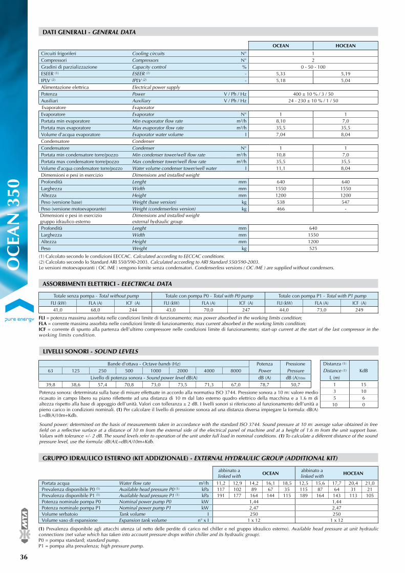
36
®
OC
EAN
350
DATI GENERALI - GENERAL DATA
(1) Calcolato secondo le condizioni EECCAC. Calculated according to EECCAC conditions.(2) Calcolato secondo lo Standard ARI 550/590-2003. Calculated according to ARI Standard 550/590-2003.Le versioni motoevaporanti ( OC /ME ) vengono fornite senza condensatori. Condenserless versions ( OC /ME ) are supplied without condensers.
Bande d'ottava - Octave bands (Hz) Potenza Pressione63 125 250 500 1000 2000 4000 8000 Power Pressure
Livello di potenza sonora - Sound power level dB(A) dB (A) dB (A)10m
39,8 38,6 57,4 70,8 73,0 73,5 71,3 67,0 78,7 50,7
LIVELLI SONORI - SOUND LEVELS
Distanza (1)
KdBDistance (1)
L (m)1 153 105 6
10 0
OCEAN HOCEAN
Circuiti frigoriferi Cooling circuits N° 1Compressori Compressors N° 2Gradini di parzializzazione Capacity control % 0 - 50 - 100ESEER (1) ESEER (1) - 5,33 5,19IPLV (2) IPLV (2) - 5,18 5,04Alimentazione elettrica Electrical power supplyPotenza Power V / Ph / Hz 400 ± 10 % / 3 / 50Ausiliari Auxiliary V / Ph / Hz 24 - 230 ± 10 % / 1 / 50Evaporatore EvaporatorEvaporatore Evaporator N° 1 1Portata min evaporatore Min evaporator fl ow rate m3/h 8,10 7,0Portata max evaporatore Max evaporator fl ow rate m3/h 35,5 35,5Volume d’acqua evaporatore Evaporator water volume I 7,04 8,04Condensatore CondenserCondensatore Condenser N° 1 1Portata min condensatore torre/pozzo Min condenser tower/well fl ow rate m3/h 10,8 7,0Portata max condensatore torre/pozzo Max condenser tower/well fl ow rate m3/h 35,5 35,5Volume d’acqua condensatore torre/pozzo Water volume condenser tower/well water I 11,1 8,04Dimensioni e pesi in esercizio Dimensions and installed weightProfondità Lenght mm 640 640Larghezza Width mm 1550 1550Altezza Height mm 1200 1200Peso (versione base) Weight (base version) kg 538 547Peso (versione motoevaporante) Weight (condenserless version) kg 466 -Dimensioni e pesi in esercizio gruppo idraulico esterno
Dimensions and installed weight external hydraulic group
Profondità Lenght mm 640Larghezza Width mm 1550Altezza Height mm 1200Peso Weight kg 525
FLI = potenza massima assorbita nelle condizioni limite di funzionamento; max power absorbed in the working limits condition; FLA = corrente massima assorbita nelle condizioni limite di funzionamento; max current absorbed in the working limits condition; ICF = corrente di spunto alla partenza dell’ultimo compressore nelle condizioni limite di funzionamento; start-up current at the start of the last compressor in the working limits condition.
ASSORBIMENTI ELETTRICI - ELECTRICAL DATA
Totale senza pompa - Total without pump Totale con pompa P0 - Total with P0 pump Totale con pompa P1 - Total with P1 pump
FLI (kW) FLA (A) ICF (A) FLI (kW) FLA (A) ICF (A) FLI (kW) FLA (A) ICF (A)41,0 68,0 244 43,0 70,0 247 44,0 73,0 249
Potenza sonora: determinata sulla base di misure effettuate in accordo alla normativa ISO 3744. Pressione sonora a 10 m: valore medio ricavato in campo libero su piano riflettente ad una distanza di 10 m dal lato esterno quadro elettrico della macchina e a 1.6 m di altezza rispetto alla base di appoggio dell’unità. Valori con tolleranza ± 2 dB. I livelli sonori si riferiscono al funzionamento dell’unità a pieno carico in condizioni nominali. (1) Per calcolare il livello di pressione sonora ad una distanza diversa impiegare la formula: dB(A)L=dB(A)10m+Kdb.
Sound power: determined on the basis of measurements taken in accordance with the standard ISO 3744. Sound pressure at 10 m: average value obtained in free field on a reflective surface at a distance of 10 m from the external side of the electrical panel of machine and at a height of 1.6 m from the unit support base. Values with tolerance +/- 2 dB. The sound levels refer to operation of the unit under full load in nominal conditions. (1) To calculate a different distance of the sound pressure level, use the formula: dB(A)L=dB(A)10m+Kdb.
GRUPPO IDRAULICO ESTERNO (KIT ADDIZIONALE) - EXTERNAL HYDRAULIC GROUP (ADDITIONAL KIT)
abbinato a linked with
OCEANabbinato a linked with
HOCEAN
Portata acqua Water fl ow rate m3/h 11,2 12,9 14,2 16,1 18,5 12,5 15,6 17,7 20,4 21,0Prevalenza disponibile P0 (1) Available head pressure P0 (1) kPa 117 102 89 67 35 115 87 64 31 21Prevalenza disponibile P1 (1) Available head pressure P1 (1) kPa 191 177 164 144 115 189 164 143 113 105Potenza nominale pompa P0 Nominal power pump P0 kW 1,44 1,44Potenza nominale pompa P1 Nominal power pump P1 kW 2,47 2,47Volume serbatoio Tank volume I 250 250Volume vaso di espansione Expansion tank volume n° x I 1 x 12 1 x 12
(1) Prevalenza disponibile agli attacchi utenza (al netto delle perdite di carico nel chiller e nel gruppo idraulico esterno). Available head pressure at unit hydraulic connections (net value which has taken into account pressure drops within chiller and its hydraulic group).P0 = pompa standard; standard pump.P1 = pompa alta prevalenza; high pressure pump.

®
37
OC
EAN
350
Conditioning your ambient, maximising your comfort.
PRESTAZIONI UNITÀ SOLO FREDDO - PERFORMANCE DATA CHILLER UNIT
Temperatura uscita acqua al condensatore - Outlet water condenser temperature (°C)t max (*)
(°C)35 38 40 45 48 50
Pf Pa Fw Pf Pa Fw Pf Pa Fw Pf Pa Fw Pf Pa Fw Pf Pa Fwtu (°C) (kW) (kW) (m3/h) (kW) (kW) (m3/h) (kW) (kW) (m3/h) (kW) (kW) (m3/h) (kW) (kW) (m3/h) (kW) (kW) (m3/h)
5 106 24,9 18,2 102 26,4 17,6 100 27,6 17,2 94,1 30,6 16,2 90,4 32,5 15,6 87,8 33,9 15,1 506 110 25,0 18,9 106 26,6 18,3 104 27,7 17,9 97,6 30,7 16,8 93,8 32,6 16,1 91,1 34,1 15,7 507 114 25,1 19,6 110 26,7 18,9 108 27,8 18,5 101 30,8 17,4 97,1 32,8 16,7 94,5 34,2 16,3 508 118 25,2 20,3 114 26,8 19,6 111 27,9 19,2 105 31,0 18,0 101 33,0 17,3 98,0 34,3 16,9 509 122 25,4 21,0 118 27,0 20,3 115 28,0 19,9 109 31,1 18,7 104 33,1 18,0 101 34,5 17,5 50
10 126 25,5 21,7 122 27,1 21,1 119 28,2 20,6 112 31,2 19,4 108 33,3 18,6 105 34,7 18,1 50
OC
Acqua di torre - Tower water
Acqua di pozzo - Well waterTemperatura uscita acqua al condensatore - Outlet water condenser temperature (°C)
t max (*)(°C)
30 32 34 36 38 40Pf Pa Fw Pf Pa Fw Pf Pa Fw Pf Pa Fw Pf Pa Fw Pf Pa Fw
tu (°C) (kW) (kW) (m3/h) (kW) (kW) (m3/h) (kW) (kW) (m3/h) (kW) (kW) (m3/h) (kW) (kW) (m3/h) (kW) (kW) (m3/h)
5 113 21,9 19,4 111 22,8 19,0 108 23,8 18,7 106 24,7 18,3 104 25,7 17,9 102 26,8 17,5 506 117 22,0 20,1 115 22,9 19,7 112 23,9 19,3 110 24,8 19,0 108 25,9 18,5 105 27,0 18,1 507 121 22,1 20,8 119 23,1 20,4 116 24,0 20,0 114 25,0 19,6 112 26,0 19,2 109 27,1 18,8 508 125 22,2 21,6 123 23,1 21,2 120 24,1 20,8 118 25,1 20,3 116 26,1 19,9 113 27,2 19,5 509 130 22,3 22,3 127 23,3 21,9 125 24,2 21,5 122 25,2 21,0 120 26,2 20,6 117 27,4 20,2 50
10 134 22,4 23,1 132 23,4 22,7 129 24,3 22,2 127 25,3 21,8 124 26,3 21,4 121 27,5 20,9 50
OC
PRESTAZIONI UNITÀ POMPA DI CALORE - PERFORMANCE DATA HEAT PUMP UNIT
Temperatura uscita acqua al condensatore - Outlet water condenser temperature (°C)t max (*)
(°C)35 38 40 45 48 50
Pf Pa Fw Pf Pa Fw Pf Pa Fw Pf Pa Fw Pf Pa Fw Pf Pa Fwtu (°C) (kW) (kW) (m3/h) (kW) (kW) (m3/h) (kW) (kW) (m3/h) (kW) (kW) (m3/h) (kW) (kW) (m3/h) (kW) (kW) (m3/h)
5 103 24,8 17,7 100 26,4 17,1 97,4 27,4 16,8 91,5 30,4 15,8 87,8 32,4 15,1 85,4 33,7 14,7 506 107 24,9 18,4 103 26,5 17,8 101 27,6 17,4 94,9 30,6 16,3 91,1 32,5 15,7 88,5 34,0 15,2 507 111 25,0 19,1 107 26,6 18,4 105 27,7 18,0 98,4 30,7 16,9 94,6 32,7 16,3 91,8 34,1 15,8 508 115 25,2 19,7 111 26,7 19,1 108 27,8 18,7 102 30,8 17,6 97,9 32,9 16,9 95,3 34,2 16,4 509 119 25,3 20,4 115 26,8 19,8 112 28,0 19,3 106 31,0 18,2 102 33,0 17,5 98,8 34,3 17,0 50
10 123 25,4 21,2 119 27,0 20,5 116 28,1 20,0 109 31,1 18,9 105 33,1 18,1 102 34,6 17,6 50
HOC
Raffreddamento (acqua di torre) - Cooling (tower water)
Raffreddamento (acqua di pozzo) - Cooling (well water)
Riscaldamento (acqua di torre / pozzo) - Heating (tower / well water)
PRESTAZIONI UNITÀ MOTOEVAPORANTE - PERFORMANCE DATA CONDENSERLESS UNIT
Temperatura uscita acqua al condensatore - Outlet water condenser temperature (°C)t max (*)
(°C)30 32 34 36 38 40
Pf Pa Fw Pf Pa Fw Pf Pa Fw Pf Pa Fw Pf Pa Fw Pf Pa Fwtu (°C) (kW) (kW) (m3/h) (kW) (kW) (m3/h) (kW) (kW) (m3/h) (kW) (kW) (m3/h) (kW) (kW) (m3/h) (kW) (kW) (m3/h)
5 110 21,8 18,9 108 22,7 18,5 105 23,7 18,1 103 24,6 17,8 101 25,7 17,4 98,9 26,7 17,0 506 114 21,9 19,6 112 22,8 19,2 109 23,7 18,8 107 24,7 18,5 105 25,8 18,1 102 26,9 17,6 507 118 22,0 20,3 116 23,0 19,9 113 23,9 19,5 111 24,9 19,1 109 25,9 18,7 106 26,9 18,3 508 122 22,1 21,0 120 23,0 20,6 117 24,0 20,2 115 25,0 19,8 113 26,0 19,4 110 27,1 19,0 509 126 22,2 21,8 124 23,1 21,4 122 24,1 20,9 119 25,1 20,5 117 26,1 20,1 114 27,2 19,6 50
10 131 22,3 22,5 128 23,3 22,1 126 24,2 21,7 123 25,2 21,2 121 26,2 20,8 118 27,3 20,3 50
HOC
Temperatura uscita acqua al condensatore - Outlet water condenser temperature (°C)t min (**)
(°C)2 5 7 10 13 15
Ph Pa Fw Ph Pa Fw Ph Pa Fw Ph Pa Fw Ph Pa Fw Ph Pa Fwtc (°C) (kW) (kW) (m3/h) (kW) (kW) (m3/h) (kW) (kW) (m3/h) (kW) (kW) (m3/h) (kW) (kW) (m3/h) (kW) (kW) (m3/h)
35 108 25,3 18,5 119 25,7 20,7 127 26,0 21,7 138,09 26,4 23,9 150 26,8 26,1 159 27,1 27,6 238 106 26,8 18,4 118 27,4 20,2 125 27,6 21,7 136,08 28,1 23,6 148 28,5 25,7 157 28,9 27,2 240 106 28,0 18,3 117 28,5 20,3 124 28,8 21,3 134,80 29,2 23,4 147 29,7 25,2 155 30,0 26,9 245 104 31,1 18,1 114 31,6 19,9 121 31,9 21,0 131,49 32,4 22,9 143 32,9 24,8 151 33,3 26,2 250 102 34,5 17,8 112 35,1 19,5 118 35,4 20,6 128,29 36,0 22,1 139 36,5 24,2 146 36,9 25,3 2
HOC
Temperatura uscita acqua al condensatore - Outlet water condenser temperature (°C) t max (*)Dew (°C)
35 40 45 50 55Pf Pa Fw Pf Pa Fw Pf Pa Fw Pf Pa Fw Pf Pa Fw
tu (°C) (kW) (kW) (m3/h) (kW) (kW) (m3/h) (kW) (kW) (m3/h) (kW) (kW) (m3/h) (kW) (kW) (m3/h)
5 115 21,1 19,7 109 23,4 18,8 103 26,0 17,8 97,2 29,0 16,7 90,8 32,3 15,6 646 119 21,1 20,5 113 23,5 19,5 107 26,1 18,5 101 29,0 17,4 94,3 32,3 16,2 647 123 21,2 21,3 118 23,5 20,2 111 26,1 19,2 105 29,1 18,1 98,0 32,4 16,9 648 128 21,2 22,0 122 23,5 21,0 116 26,1 19,9 109 29,1 18,7 101,7 32,5 17,5 649 133 21,2 22,8 126 23,6 21,8 120 26,2 20,6 113 29,2 19,4 105,6 32,5 18,2 64
10 137 21,3 23,7 131 23,6 22,6 124 26,2 21,4 117 29,2 20,2 109,5 32,6 18,9 64
OC / ME
tu: temperatura acqua uscita evaporatore, evaporator outlet water temperature; tc: temperatura acqua uscita condensatore, condensator outlet water temperature; Pf: potenza frigorifera, cooling capacity; Pa: potenza assorbita dai compressori, power absorbed by the compressors; Ph: potenza termica, heating capacity; Fw: portata d’acqua, water flow rate. I valori nominali sono riferiti alle seguenti condizioni: T evaporatore 5 °C, T condensatore torre (in modalità chiller) 5 °C, T condensatore pozzo (in modalità chiller) 10 °C, T condensatore (in modalità pompa di calore) 5 °C, T evaporatore (in modalità pompa di calore 5 °C). Per la determinazione delle prestazioni con T tra ingresso e uscita acqua dagli scambiatori diversa da quella nominale, utilizzare le tabelle “Coefficienti correttivi T”. È permessa l’interpolazione dei valori ma non la loro estrapolazione. (*): Temperatura massima al condensatore. Se la temperatura al condensatore è superiore a “t max” il refrigeratore non si blocca ma interviene il sistema “unloading” di parzializzazione (solo per i modelli dal 200 al 350). (**): Temperatura minima all’evaporatore. Se la temperatura all’evaporatore è inferiore a “t min” la pompa di calore non si blocca ma interviene il sistema “unloading” di parzializzazione (solo per i modelli dal 200 al 350). The nominal values are refered to: T evaporator 5 °C, T condenser tower water (chiller mode) 5 °C, T condenser well water (chiller mode) 10 °C, T condenser (heat pump mode) 5 °C, T evaporator (heat pump mode) 5 °C. To calculate performances at differing water inlet/outlet T levels, refer to the “ T correction factors” table. Interpolation is allowed, extrapolation is not permitted. (*): Maximum outlet water temperature in the condenser. When the condenser temperature is higher than the “t max” the chiller doesn’t stop but the “unloading” system capacity control is activated (only for the models from 200 to 350). (**): Min. evaporator temperature. When the evaporator temperature is lower than the “t min” the heat pump doesn’t stop but the “unloading” system capacity control is activated (only for the models from 200 to 350).

38
®
OC
EAN
400
DATI GENERALI - GENERAL DATA
(1) Calcolato secondo le condizioni EECCAC. Calculated according to EECCAC conditions.(2) Calcolato secondo lo Standard ARI 550/590-2003. Calculated according to ARI Standard 550/590-2003.Le versioni motoevaporanti ( OC /ME ) vengono fornite senza condensatori. Condenserless versions ( OC /ME ) are supplied without condensers.
Bande d'ottava - Octave bands (Hz) Potenza Pressione63 125 250 500 1000 2000 4000 8000 Power Pressure
Livello di potenza sonora - Sound power level dB(A) dB (A) dB (A)10m
41,6 40,8 58,3 70,4 75,0 74,1 72,8 67,6 79,7 51,7
LIVELLI SONORI - SOUND LEVELS
Distanza (1)
KdBDistance (1)
L (m)1 153 105 6
10 0
OCEAN HOCEAN
Circuiti frigoriferi Cooling circuits N° 2Compressori Compressors N° 1Gradini di parzializzazione Capacity control % 0 - 50 - 100ESEER (1) ESEER (1) - 5,22 5,32IPLV (2) IPLV (2) - 5,11 5,21Alimentazione elettrica Electrical power supplyPotenza Power V / Ph / Hz 400 ± 10 % / 3 / 50Ausiliari Auxiliary V / Ph / Hz 24 - 230 ± 10 % / 1 / 50Evaporatore EvaporatorEvaporatore Evaporator N° 1 1Portata min evaporatore Min evaporator fl ow rate m3/h 9,50 11,8Portata max evaporatore Max evaporator fl ow rate m3/h 47,2 47,2Volume d’acqua evaporatore Evaporator water volume I 7,20 8,80Condensatore CondenserCondensatore Condenser N° 1 1Portata min condensatore torre/pozzo Min condenser tower/well fl ow rate m3/h 13,3 11,8Portata max condensatore torre/pozzo Max condenser tower/well fl ow rate m3/h 47,2 47,2Volume d’acqua condensatore torre/pozzo Water volume condenser tower/well water I 11,0 8,80Dimensioni e pesi in esercizio Dimensions and installed weightProfondità Lenght mm 720 720Larghezza Width mm 1750 1750Altezza Height mm 1200 1200Peso (versione base) Weight (base version) kg 608 654Peso (versione motoevaporante) Weight (condenserless version) kg 535 -Dimensioni e pesi in esercizio gruppo idraulico esterno
Dimensions and installed weight external hydraulic group
Profondità Lenght mm 720Larghezza Width mm 1750Altezza Height mm 1200Peso Weight kg 696
FLI = potenza massima assorbita nelle condizioni limite di funzionamento; max power absorbed in the working limits condition; FLA = corrente massima assorbita nelle condizioni limite di funzionamento; max current absorbed in the working limits condition; ICF = corrente di spunto alla partenza dell’ultimo compressore nelle condizioni limite di funzionamento; start-up current at the start of the last compressor in the working limits condition.
ASSORBIMENTI ELETTRICI - ELECTRICAL DATA
Totale senza pompa - Total without pump Totale con pompa P0 - Total with P0 pump Totale con pompa P1 - Total with P1 pump
FLI (kW) FLA (A) ICF (A) FLI (kW) FLA (A) ICF (A) FLI (kW) FLA (A) ICF (A)48,0 77,0 254 51,0 83,0 260 53,0 85,0 262
Potenza sonora: determinata sulla base di misure effettuate in accordo alla normativa ISO 3744. Pressione sonora a 10 m: valore medio ricavato in campo libero su piano riflettente ad una distanza di 10 m dal lato esterno quadro elettrico della macchina e a 1.6 m di altezza rispetto alla base di appoggio dell’unità. Valori con tolleranza ± 2 dB. I livelli sonori si riferiscono al funzionamento dell’unità a pieno carico in condizioni nominali. (1) Per calcolare il livello di pressione sonora ad una distanza diversa impiegare la formula: dB(A)L=dB(A)10m+Kdb.
Sound power: determined on the basis of measurements taken in accordance with the standard ISO 3744. Sound pressure at 10 m: average value obtained in free field on a reflective surface at a distance of 10 m from the external side of the electrical panel of machine and at a height of 1.6 m from the unit support base. Values with tolerance +/- 2 dB. The sound levels refer to operation of the unit under full load in nominal conditions. (1) To calculate a different distance of the sound pressure level, use the formula: dB(A)L=dB(A)10m+Kdb.
GRUPPO IDRAULICO ESTERNO (KIT ADDIZIONALE) - EXTERNAL HYDRAULIC GROUP (ADDITIONAL KIT)
abbinato a linked with
OCEANabbinato a linked with
HOCEAN
Portata acqua Water fl ow rate m3/h 13,0 16,8 20,4 25,0 28,9 16,6 19,8 22,6 26,7 31,5Prevalenza disponibile P0 (1) Available head pressure P0 (1) kPa 261 231 194 136 77 247 221 194 148 84Prevalenza disponibile P1 (1) Available head pressure P1 (1) kPa 328 299 263 205 146 315 289 263 216 153Potenza nominale pompa P0 Nominal power pump P0 kW 3,73 3,73Potenza nominale pompa P1 Nominal power pump P1 kW 4,80 4,80Volume serbatoio Tank volume I 350 350Volume vaso di espansione Expansion tank volume n° x I 2 x 12 2 x 12
(1) Prevalenza disponibile agli attacchi utenza (al netto delle perdite di carico nel chiller e nel gruppo idraulico esterno). Available head pressure at unit hydraulic connections (net value which has taken into account pressure drops within chiller and its hydraulic group).P0 = pompa standard; standard pump.P1 = pompa alta prevalenza; high pressure pump.

®
39
OC
EAN
400
Conditioning your ambient, maximising your comfort.
PRESTAZIONI UNITÀ SOLO FREDDO - PERFORMANCE DATA CHILLER UNIT
Temperatura uscita acqua al condensatore - Outlet water condenser temperature (°C)t max (*)
(°C)35 38 40 45 48 50
Pf Pa Fw Pf Pa Fw Pf Pa Fw Pf Pa Fw Pf Pa Fw Pf Pa Fwtu (°C) (kW) (kW) (m3/h) (kW) (kW) (m3/h) (kW) (kW) (m3/h) (kW) (kW) (m3/h) (kW) (kW) (m3/h) (kW) (kW) (m3/h)
5 123 28,6 21,1 119 30,4 20,4 116 31,6 20,0 110 34,9 18,9 106 37,1 18,2 103 38,6 17,7 506 127 28,8 21,9 123 30,5 21,2 120 31,8 20,7 114 35,1 19,6 109 37,3 18,8 107 38,9 18,3 507 132 28,9 22,7 127 30,7 21,9 125 31,9 21,5 118 35,3 20,3 113 37,5 19,5 111 39,0 19,0 508 136 29,1 23,5 132 30,9 22,7 129 32,1 22,3 122 35,4 21,0 117 37,7 20,2 115 39,2 19,7 509 141 29,2 24,3 137 31,0 23,6 134 32,3 23,0 126 35,7 21,8 122 37,9 21,0 119 39,4 20,4 50
10 146 29,4 25,1 141 31,2 24,4 138 32,4 23,9 131 35,8 22,5 126 38,1 21,7 123 39,7 21,2 50
OC
Acqua di torre - Tower water
Acqua di pozzo - Well waterTemperatura uscita acqua al condensatore - Outlet water condenser temperature (°C)
t max (*)(°C)
30 32 34 36 38 40Pf Pa Fw Pf Pa Fw Pf Pa Fw Pf Pa Fw Pf Pa Fw Pf Pa Fw
tu (°C) (kW) (kW) (m3/h) (kW) (kW) (m3/h) (kW) (kW) (m3/h) (kW) (kW) (m3/h) (kW) (kW) (m3/h) (kW) (kW) (m3/h)
5 130 25,4 22,4 128 26,2 22,1 126 27,3 21,6 123 28,3 21,2 121 29,5 20,8 118 30,7 20,3 506 135 25,4 23,2 133 26,4 22,8 130 27,4 22,4 128 28,5 22,0 125 29,6 21,5 122 30,8 21,1 507 140 25,5 24,1 137 26,5 23,7 135 27,5 23,2 132 28,6 22,8 130 29,8 22,3 127 31,0 21,9 508 145 25,6 25,0 142 26,6 24,5 140 27,6 24,1 137 28,8 23,6 134 29,9 23,1 131 31,1 22,6 509 150 25,8 25,8 147 26,8 25,4 145 27,8 24,9 142 29,0 24,4 139 30,1 23,9 136 31,2 23,5 50
10 155 25,9 26,7 152 26,9 26,3 150 28,0 25,8 147 29,1 25,3 144 30,3 24,8 141 31,4 24,3 50
OC
PRESTAZIONI UNITÀ POMPA DI CALORE - PERFORMANCE DATA HEAT PUMP UNIT
Temperatura uscita acqua al condensatore - Outlet water condenser temperature (°C)t max (*)
(°C)35 38 40 45 48 50
Pf Pa Fw Pf Pa Fw Pf Pa Fw Pf Pa Fw Pf Pa Fw Pf Pa Fwtu (°C) (kW) (kW) (m3/h) (kW) (kW) (m3/h) (kW) (kW) (m3/h) (kW) (kW) (m3/h) (kW) (kW) (m3/h) (kW) (kW) (m3/h)
5 125 28,7 21,6 121 30,5 20,9 119 31,7 20,4 112 35,0 19,3 108 37,3 18,6 105 38,8 18,1 506 130 28,9 22,3 126 30,6 21,7 123 31,9 21,2 116 35,2 20,0 112 37,4 19,2 109 38,9 18,8 507 134 29,0 23,2 130 30,8 22,5 128 32,0 22,0 120 35,4 20,7 116 37,6 20,0 113 39,2 19,4 508 139 29,2 24,0 135 31,0 23,2 132 32,2 22,8 125 35,6 21,5 120 37,8 20,7 117 39,4 20,1 509 144 29,4 24,8 140 31,1 24,1 137 32,4 23,5 129 35,8 22,2 124 38,0 21,4 121 39,6 20,9 50
10 149 29,6 25,7 145 31,3 24,9 141 32,6 24,4 134 36,0 23,0 129 38,2 22,2 125 39,8 21,6 50
HOC
Raffreddamento (acqua di torre) - Cooling (tower water)
Raffreddamento (acqua di pozzo) - Cooling (well water)
PRESTAZIONI UNITÀ MOTOEVAPORANTE - PERFORMANCE DATA CONDENSERLESS UNIT
Temperatura uscita acqua al condensatore - Outlet water condenser temperature (°C)t max (*)
(°C)30 32 34 36 38 40
Pf Pa Fw Pf Pa Fw Pf Pa Fw Pf Pa Fw Pf Pa Fw Pf Pa Fwtu (°C) (kW) (kW) (m3/h) (kW) (kW) (m3/h) (kW) (kW) (m3/h) (kW) (kW) (m3/h) (kW) (kW) (m3/h) (kW) (kW) (m3/h)
5 133 25,4 22,9 131 26,3 22,6 129 27,3 22,1 126 28,4 21,7 124 29,5 21,3 121 30,7 20,8 506 138 25,5 23,8 136 26,5 23,4 133 27,5 22,9 131 28,6 22,5 128 29,7 22,0 125 30,9 21,6 507 143 25,6 24,7 141 26,6 24,2 138 27,6 23,8 135 28,7 23,3 133 29,9 22,8 130 31,0 22,3 508 148 25,7 25,5 146 26,7 25,1 143 27,8 24,6 140 28,8 24,1 137 30,0 23,6 134 31,2 23,1 509 153 25,8 26,4 151 26,9 26,0 148 27,9 25,5 145 29,0 25,0 142 30,1 24,5 139 31,4 24,0 50
10 159 26,0 27,3 156 27,0 26,9 153 28,1 26,4 150 29,1 25,9 147 30,3 25,3 144 31,5 24,8 50
HOC
Temperatura uscita acqua al condensatore - Outlet water condenser temperature (°C) t max (*)Dew (°C)
35 40 45 50 55Pf Pa Fw Pf Pa Fw Pf Pa Fw Pf Pa Fw Pf Pa Fw
tu (°C) (kW) (kW) (m3/h) (kW) (kW) (m3/h) (kW) (kW) (m3/h) (kW) (kW) (m3/h) (kW) (kW) (m3/h)
5 132 24,6 22,7 126 27,1 21,7 119 30,0 20,6 113 33,3 19,4 105,6 37,0 18,2 646 137 24,6 23,6 131 27,2 22,5 124 30,1 21,3 117 33,4 20,1 109,7 37,1 18,9 647 142 24,7 24,5 136 27,3 23,3 129 30,2 22,1 121 33,5 20,9 113,9 37,2 19,6 648 147 24,7 25,4 141 27,3 24,2 133 30,2 23,0 126 33,6 21,7 118,2 37,3 20,4 649 153 24,8 26,3 146 27,4 25,1 138 30,3 23,8 131 33,6 22,5 122,6 37,4 21,1 64
10 158 24,8 27,3 151 27,5 26,0 143 30,4 24,7 135 33,7 23,3 127,3 37,5 21,9 64
OC / ME
tu: temperatura acqua uscita evaporatore, evaporator outlet water temperature; Pf: potenza frigorifera, cooling capacity; Pa: potenza assorbita dai compressori, power absorbed by the compressors; Fw: portata d’acqua, water flow rate. I valori nominali sono riferiti alle seguenti condizioni: T evaporatore 5 °C, T condensatore torre (in modalità chiller) 5 °C, T condensatore pozzo (in modalità chiller) 10 °C; la resa termica si determina con la seguente formula: potenza termica = potenza frigorifera + potenza assorbita dai compressori, the termal load can be calculated using the following formula: heating capacity = cooling capacity + absorbed power. Per la determinazione delle prestazioni con T tra ingresso e uscita acqua dagli scambiatori diversa da quella nominale, utilizzare le tabelle “Coefficienti correttivi
T”. È permessa l’interpolazione dei valori ma non la loro estrapolazione. (*): Temperatura massima al condensatore. Se la temperatura al condensatore è superiore a “t max” il refrigeratore non si blocca ma interviene il sistema “unloading” di parzializzazione (solo per i modelli dal 200 al 350). Se la temperatura all’evaporatore è inferiore a “t min” la pompa di calore non si blocca ma interviene il sistema “unloading” di parzializzazione (solo per i modelli dal 200 al 350). The nominal values are refered to: T evaporator 5 °C, T condenser tower water (chiller mode) 5 °C, T condenser well water (chiller mode) 10 °C. To calculate performances at differing water inlet/outlet T levels, refer to the “ T correction factors” table. Interpolation is allowed, extrapolation is not permitted. (*): Maximum outlet water temperature in the condenser. When the condenser temperature is higher than the “t max” the chiller doesn’t stop but the “unloading” system capacity control is activated (only for the models from 200 to 350). When the evaporator temperature is lower than the “t min” the heat pump doesn’t stop but the “unloading” system capacity control is activated (only for the models from 200 to 350).

40
®
OC
EAN
500
DATI GENERALI - GENERAL DATA
(1) Calcolato secondo le condizioni EECCAC. Calculated according to EECCAC conditions.(2) Calcolato secondo lo Standard ARI 550/590-2003. Calculated according to ARI Standard 550/590-2003.Le versioni motoevaporanti ( OC /ME ) vengono fornite senza condensatori. Condenserless versions ( OC /ME ) are supplied without condensers.
Bande d'ottava - Octave bands (Hz) Potenza Pressione63 125 250 500 1000 2000 4000 8000 Power Pressure
Livello di potenza sonora - Sound power level dB(A) dB (A) dB (A)10m
35,7 39,3 61,3 76,8 74,9 73,3 71,2 68,5 80,8 52,9
LIVELLI SONORI - SOUND LEVELS
Distanza (1)
KdBDistance (1)
L (m)1 153 105 6
10 0
OCEAN HOCEAN
Circuiti frigoriferi Cooling circuits N° 2Compressori Compressors N° 1Gradini di parzializzazione Capacity control % 0 - 50 - 100ESEER (1) ESEER (1) - 5,29 5,23IPLV (2) IPLV (2) - 5,18 5,11Alimentazione elettrica Electrical power supplyPotenza Power V / Ph / Hz 400 ± 10 % / 3 / 50Ausiliari Auxiliary V / Ph / Hz 24 - 230 ± 10 % / 1 / 50Evaporatore EvaporatorEvaporatore Evaporator N° 1 1Portata min evaporatore Min evaporator fl ow rate m3/h 11,8 13,6Portata max evaporatore Max evaporator fl ow rate m3/h 47,2 47,2Volume d’acqua evaporatore Evaporator water volume I 8,80 9,76Condensatore CondenserCondensatore Condenser N° 1 1Portata min condensatore torre/pozzo Min condenser tower/well fl ow rate m3/h 14,8 13,6Portata max condensatore torre/pozzo Max condenser tower/well fl ow rate m3/h 47,2 47,2Volume d’acqua condensatore torre/pozzo Water volume condenser tower/well water I 12,3 9,76Dimensioni e pesi in esercizio Dimensions and installed weightProfondità Lenght mm 720 720Larghezza Width mm 1750 1750Altezza Height mm 1200 1200Peso (versione base) Weight (base version) kg 682 670Peso (versione motoevaporante) Weight (condenserless version) kg 600 -Dimensioni e pesi in esercizio gruppo idraulico esterno
Dimensions and installed weight external hydraulic group
Profondità Lenght mm 720Larghezza Width mm 1750Altezza Height mm 1200Peso Weight kg 696
FLI = potenza massima assorbita nelle condizioni limite di funzionamento; max power absorbed in the working limits condition; FLA = corrente massima assorbita nelle condizioni limite di funzionamento; max current absorbed in the working limits condition; ICF = corrente di spunto alla partenza dell’ultimo compressore nelle condizioni limite di funzionamento; start-up current at the start of the last compressor in the working limits condition.
ASSORBIMENTI ELETTRICI - ELECTRICAL DATA
Totale senza pompa - Total without pump Totale con pompa P0 - Total with P0 pump Totale con pompa P1 - Total with P1 pump
FLI (kW) FLA (A) ICF (A) FLI (kW) FLA (A) ICF (A) FLI (kW) FLA (A) ICF (A)58,0 94,0 317 62,0 101 323 63,0 103 325
Potenza sonora: determinata sulla base di misure effettuate in accordo alla normativa ISO 3744. Pressione sonora a 10 m: valore medio ricavato in campo libero su piano riflettente ad una distanza di 10 m dal lato esterno quadro elettrico della macchina e a 1.6 m di altezza rispetto alla base di appoggio dell’unità. Valori con tolleranza ± 2 dB. I livelli sonori si riferiscono al funzionamento dell’unità a pieno carico in condizioni nominali. (1) Per calcolare il livello di pressione sonora ad una distanza diversa impiegare la formula: dB(A)L=dB(A)10m+Kdb.
Sound power: determined on the basis of measurements taken in accordance with the standard ISO 3744. Sound pressure at 10 m: average value obtained in free field on a reflective surface at a distance of 10 m from the external side of the electrical panel of machine and at a height of 1.6 m from the unit support base. Values with tolerance +/- 2 dB. The sound levels refer to operation of the unit under full load in nominal conditions. (1) To calculate a different distance of the sound pressure level, use the formula: dB(A)L=dB(A)10m+Kdb.
GRUPPO IDRAULICO ESTERNO (KIT ADDIZIONALE) - EXTERNAL HYDRAULIC GROUP (ADDITIONAL KIT)
abbinato a linked with
OCEANabbinato a linked with
HOCEAN
Portata acqua Water fl ow rate m3/h 16,1 18,5 22,7 26,7 30,7 18,5 22,1 26,1 30,7 34,6Prevalenza disponibile P0 (1) Available head pressure P0 (1) kPa 244 223 180 130 72 236 204 163 105 49Prevalenza disponibile P1 (1) Available head pressure P1 (1) kPa 313 292 249 199 141 305 273 231 174 118Potenza nominale pompa P0 Nominal power pump P0 kW 3,73 3,73Potenza nominale pompa P1 Nominal power pump P1 kW 4,80 4,80Volume serbatoio Tank volume I 350 350Volume vaso di espansione Expansion tank volume n° x I 2 x 12 2 x 12
(1) Prevalenza disponibile agli attacchi utenza (al netto delle perdite di carico nel chiller e nel gruppo idraulico esterno). Available head pressure at unit hydraulic connections (net value which has taken into account pressure drops within chiller and its hydraulic group).P0 = pompa standard; standard pump.P1 = pompa alta prevalenza; high pressure pump.

®
41
OC
EAN
500
Conditioning your ambient, maximising your comfort.
PRESTAZIONI UNITÀ SOLO FREDDO - PERFORMANCE DATA CHILLER UNIT
Temperatura uscita acqua al condensatore - Outlet water condenser temperature (°C)t max (*)
(°C)35 38 40 45 48 50
Pf Pa Fw Pf Pa Fw Pf Pa Fw Pf Pa Fw Pf Pa Fw Pf Pa Fwtu (°C) (kW) (kW) (m3/h) (kW) (kW) (m3/h) (kW) (kW) (m3/h) (kW) (kW) (m3/h) (kW) (kW) (m3/h) (kW) (kW) (m3/h)
5 150 35,0 25,8 146 37,3 25,1 143 38,9 24,6 135 43,0 23,3 130 45,8 22,4 127 47,6 21,9 506 155 35,2 26,7 151 37,5 26,0 148 39,1 25,5 140 43,3 24,1 135 46,0 23,2 132 47,8 22,7 507 161 35,5 27,6 156 37,7 26,9 153 39,4 26,4 145 43,6 25,0 140 46,2 24,1 136 48,2 23,4 508 166 35,6 28,6 162 38,0 27,8 158 39,6 27,3 150 43,8 25,8 145 46,6 24,9 141 48,4 24,3 509 172 35,9 29,6 167 38,2 28,8 164 39,9 28,2 155 44,1 26,7 150 46,8 25,8 146 48,8 25,1 50
10 178 36,1 30,6 173 38,5 29,7 169 40,1 29,2 161 44,4 27,7 155 47,1 26,7 151 49,0 26,0 50
OC
Acqua di torre - Tower water
Acqua di pozzo - Well waterTemperatura uscita acqua al condensatore - Outlet water condenser temperature (°C)
t max (*)(°C)
30 32 34 36 38 40Pf Pa Fw Pf Pa Fw Pf Pa Fw Pf Pa Fw Pf Pa Fw Pf Pa Fw
tu (°C) (kW) (kW) (m3/h) (kW) (kW) (m3/h) (kW) (kW) (m3/h) (kW) (kW) (m3/h) (kW) (kW) (m3/h) (kW) (kW) (m3/h)
5 158 30,4 27,2 156 31,8 26,8 153 33,2 26,4 151 34,6 25,9 148 36,1 25,5 145 37,7 25,0 506 164 30,5 28,2 161 31,9 27,7 159 33,4 27,3 156 34,8 26,8 153 36,4 26,4 150 37,9 25,9 507 169 30,7 29,2 167 32,1 28,7 164 33,6 28,3 161 35,1 27,8 158 36,6 27,3 155 38,1 26,8 508 175 30,9 30,2 172 32,3 29,7 170 33,8 29,2 167 35,3 28,8 164 36,8 28,2 161 38,4 27,7 509 181 31,1 31,2 178 32,5 30,7 176 34,0 30,2 173 35,5 29,7 169 37,0 29,2 166 38,6 28,6 50
10 187 31,3 32,3 184 32,8 31,8 182 34,2 31,3 178 35,7 30,8 175 37,3 30,2 172 38,8 29,6 50
OC
PRESTAZIONI UNITÀ POMPA DI CALORE - PERFORMANCE DATA HEAT PUMP UNIT
Temperatura uscita acqua al condensatore - Outlet water condenser temperature (°C)t max (*)
(°C)35 38 40 45 48 50
Pf Pa Fw Pf Pa Fw Pf Pa Fw Pf Pa Fw Pf Pa Fw Pf Pa Fwtu (°C) (kW) (kW) (m3/h) (kW) (kW) (m3/h) (kW) (kW) (m3/h) (kW) (kW) (m3/h) (kW) (kW) (m3/h) (kW) (kW) (m3/h)
5 148 35,0 25,5 144 37,3 24,8 141 38,9 24,3 134 43,1 23,0 129 45,7 22,2 126 47,6 21,6 506 153 35,2 26,4 149 37,5 25,7 146 39,1 25,2 138 43,3 23,8 134 46,0 23,0 130 47,9 22,4 507 159 35,4 27,3 154 37,8 26,6 151 39,3 26,1 143 43,5 24,7 138 46,3 23,8 135 48,1 23,2 508 164 35,7 28,3 160 38,0 27,5 156 39,6 27,0 148 43,9 25,5 143 46,5 24,6 139 48,5 24,0 509 170 35,9 29,3 165 38,3 28,4 162 39,8 27,9 153 44,1 26,4 148 46,9 25,5 144 48,7 24,9 50
10 175 36,1 30,2 171 38,5 29,4 167 40,1 28,8 159 44,4 27,3 153 47,1 26,4 149 49,1 25,7 50
HOC
Raffreddamento (acqua di torre) - Cooling (tower water)
Raffreddamento (acqua di pozzo) - Cooling (well water)
PRESTAZIONI UNITÀ MOTOEVAPORANTE - PERFORMANCE DATA CONDENSERLESS UNIT
Temperatura uscita acqua al condensatore - Outlet water condenser temperature (°C)t max (*)
(°C)30 32 34 36 38 40
Pf Pa Fw Pf Pa Fw Pf Pa Fw Pf Pa Fw Pf Pa Fw Pf Pa Fwtu (°C) (kW) (kW) (m3/h) (kW) (kW) (m3/h) (kW) (kW) (m3/h) (kW) (kW) (m3/h) (kW) (kW) (m3/h) (kW) (kW) (m3/h)
5 156 30,3 26,9 154 31,7 26,5 151 33,1 26,1 149 34,6 25,6 146 36,1 25,2 143 37,6 24,7 506 162 30,4 27,9 159 31,9 27,4 157 33,3 27,0 154 34,8 26,5 152 36,2 26,1 149 37,8 25,6 507 167 30,7 28,8 165 32,1 28,4 162 33,5 27,9 160 35,0 27,5 157 36,5 27,0 154 38,1 26,5 508 173 30,8 29,8 171 32,2 29,4 168 33,7 28,9 165 35,2 28,4 162 36,7 27,9 159 38,3 27,4 509 179 31,0 30,8 176 32,5 30,4 174 33,9 29,9 171 35,4 29,4 168 37,0 28,9 165 38,5 28,4 50
10 185 31,2 31,9 182 32,7 31,4 179 34,1 30,9 176 35,7 30,4 173 37,2 29,9 170 38,8 29,3 50
HOC
Temperatura uscita acqua al condensatore - Outlet water condenser temperature (°C) t max (*)Dew (°C)
35 40 45 50 55Pf Pa Fw Pf Pa Fw Pf Pa Fw Pf Pa Fw Pf Pa Fw
tu (°C) (kW) (kW) (m3/h) (kW) (kW) (m3/h) (kW) (kW) (m3/h) (kW) (kW) (m3/h) (kW) (kW) (m3/h)
5 160 29,1 27,6 154 32,6 26,5 147 36,5 25,3 140 40,6 24,0 131,4 45,2 22,6 646 166 29,1 28,6 160 32,7 27,5 153 36,6 26,3 145 40,8 24,9 136,2 45,3 23,5 647 172 29,2 29,6 165 32,8 28,5 158 36,7 27,2 150 40,9 25,8 141,2 45,5 24,3 648 178 29,3 30,6 171 32,9 29,5 164 36,8 28,2 156 41,0 26,8 146,5 45,6 25,2 649 184 29,4 31,7 177 33,0 30,6 170 36,9 29,2 161 41,2 27,8 151,8 45,8 26,2 64
10 191 29,5 32,8 184 33,1 31,6 176 37,0 30,3 167 41,3 28,8 157,3 45,9 27,1 64
OC / ME
tu: temperatura acqua uscita evaporatore, evaporator outlet water temperature; Pf: potenza frigorifera, cooling capacity; Pa: potenza assorbita dai compressori, power absorbed by the compressors; Fw: portata d’acqua, water flow rate. I valori nominali sono riferiti alle seguenti condizioni: T evaporatore 5 °C, T condensatore torre (in modalità chiller) 5 °C, T condensatore pozzo (in modalità chiller) 10 °C; la resa termica si determina con la seguente formula: potenza termica = potenza frigorifera + potenza assorbita dai compressori, the termal load can be calculated using the following formula: heating capacity = cooling capacity + absorbed power. Per la determinazione delle prestazioni con T tra ingresso e uscita acqua dagli scambiatori diversa da quella nominale, utilizzare le tabelle “Coefficienti correttivi
T”. È permessa l’interpolazione dei valori ma non la loro estrapolazione. (*): Temperatura massima al condensatore. Se la temperatura al condensatore è superiore a “t max” il refrigeratore non si blocca ma interviene il sistema “unloading” di parzializzazione (solo per i modelli dal 200 al 350). Se la temperatura all’evaporatore è inferiore a “t min” la pompa di calore non si blocca ma interviene il sistema “unloading” di parzializzazione (solo per i modelli dal 200 al 350). The nominal values are refered to: T evaporator 5 °C, T condenser tower water (chiller mode) 5 °C, T condenser well water (chiller mode) 10 °C. To calculate performances at differing water inlet/outlet T levels, refer to the “ T correction factors” table. Interpolation is allowed, extrapolation is not permitted. (*): Maximum outlet water temperature in the condenser. When the condenser temperature is higher than the “t max” the chiller doesn’t stop but the “unloading” system capacity control is activated (only for the models from 200 to 350). When the evaporator temperature is lower than the “t min” the heat pump doesn’t stop but the “unloading” system capacity control is activated (only for the models from 200 to 350).

42
®
OC
EAN
600
DATI GENERALI - GENERAL DATA
(1) Calcolato secondo le condizioni EECCAC. Calculated according to EECCAC conditions.(2) Calcolato secondo lo Standard ARI 550/590-2003. Calculated according to ARI Standard 550/590-2003.Le versioni motoevaporanti ( OC /ME ) vengono fornite senza condensatori. Condenserless versions ( OC /ME ) are supplied without condensers.
Bande d'ottava - Octave bands (Hz) Potenza Pressione63 125 250 500 1000 2000 4000 8000 Power Pressure
Livello di potenza sonora - Sound power level dB(A) dB (A) dB (A)10m
41,6 44,7 58,3 75,2 74,5 77,2 75,0 70,0 81,9 53,9
LIVELLI SONORI - SOUND LEVELS
Distanza (1)
KdBDistance (1)
L (m)1 153 105 6
10 0
OCEAN HOCEAN
Circuiti frigoriferi Cooling circuits N° 2Compressori Compressors N° 1Gradini di parzializzazione Capacity control % 0 - 50 - 100ESEER (1) ESEER (1) - 4,98 5,04IPLV (2) IPLV (2) - 4,89 4,95Alimentazione elettrica Electrical power supplyPotenza Power V / Ph / Hz 400 ± 10 % / 3 / 50Ausiliari Auxiliary V / Ph / Hz 24 - 230 ± 10 % / 1 / 50Evaporatore EvaporatorEvaporatore Evaporator N° 1 1Portata min evaporatore Min evaporator fl ow rate m3/h 13,3 14,8Portata max evaporatore Max evaporator fl ow rate m3/h 47,2 47,2Volume d’acqua evaporatore Evaporator water volume I 11,0 12,3Condensatore CondenserCondensatore Condenser N° 1 1Portata min condensatore torre/pozzo Min condenser tower/well fl ow rate m3/h 17,2 14,8Portata max condensatore torre/pozzo Max condenser tower/well fl ow rate m3/h 47,2 47,2Volume d’acqua condensatore torre/pozzo Water volume condenser tower/well water I 14,2 12,3Dimensioni e pesi in esercizio Dimensions and installed weightProfondità Lenght mm 720 720Larghezza Width mm 1750 1750Altezza Height mm 1200 1200Peso (versione base) Weight (base version) kg 715 702Peso (versione motoevaporante) Weight (condenserless version) kg 620 -Dimensioni e pesi in esercizio gruppo idraulico esterno
Dimensions and installed weight external hydraulic group
Profondità Lenght mm 720Larghezza Width mm 1750Altezza Height mm 1200Peso Weight kg 696
FLI = potenza massima assorbita nelle condizioni limite di funzionamento; max power absorbed in the working limits condition; FLA = corrente massima assorbita nelle condizioni limite di funzionamento; max current absorbed in the working limits condition; ICF = corrente di spunto alla partenza dell’ultimo compressore nelle condizioni limite di funzionamento; start-up current at the start of the last compressor in the working limits condition.
ASSORBIMENTI ELETTRICI - ELECTRICAL DATA
Totale senza pompa - Total without pump Totale con pompa P0 - Total with P0 pump Totale con pompa P1 - Total with P1 pump
FLI (kW) FLA (A) ICF (A) FLI (kW) FLA (A) ICF (A) FLI (kW) FLA (A) ICF (A)72,0 115 378 76,0 122 384 77,0 124 386
Potenza sonora: determinata sulla base di misure effettuate in accordo alla normativa ISO 3744. Pressione sonora a 10 m: valore medio ricavato in campo libero su piano riflettente ad una distanza di 10 m dal lato esterno quadro elettrico della macchina e a 1.6 m di altezza rispetto alla base di appoggio dell’unità. Valori con tolleranza ± 2 dB. I livelli sonori si riferiscono al funzionamento dell’unità a pieno carico in condizioni nominali. (1) Per calcolare il livello di pressione sonora ad una distanza diversa impiegare la formula: dB(A)L=dB(A)10m+Kdb.
Sound power: determined on the basis of measurements taken in accordance with the standard ISO 3744. Sound pressure at 10 m: average value obtained in free field on a reflective surface at a distance of 10 m from the external side of the electrical panel of machine and at a height of 1.6 m from the unit support base. Values with tolerance +/- 2 dB. The sound levels refer to operation of the unit under full load in nominal conditions. (1) To calculate a different distance of the sound pressure level, use the formula: dB(A)L=dB(A)10m+Kdb.
GRUPPO IDRAULICO ESTERNO (KIT ADDIZIONALE) - EXTERNAL HYDRAULIC GROUP (ADDITIONAL KIT)
abbinato a linked with
OCEANabbinato a linked with
HOCEAN
Portata acqua Water fl ow rate m3/h 20,2 22,6 25,6 28,0 31,6 22,1 24,2 28,5 33,6 37,5Prevalenza disponibile P0 (1) Available head pressure P0 (1) kPa 216 192 158 128 77 220 202 159 100 48Prevalenza disponibile P1 (1) Available head pressure P1 (1) kPa 285 261 227 196 145 289 270 227 169 118Potenza nominale pompa P0 Nominal power pump P0 kW 3,73 3,73Potenza nominale pompa P1 Nominal power pump P1 kW 4,80 4,80Volume serbatoio Tank volume I 350 350Volume vaso di espansione Expansion tank volume n° x I 2 x 12 2 x 12
(1) Prevalenza disponibile agli attacchi utenza (al netto delle perdite di carico nel chiller e nel gruppo idraulico esterno). Available head pressure at unit hydraulic connections (net value which has taken into account pressure drops within chiller and its hydraulic group).P0 = pompa standard; standard pump.P1 = pompa alta prevalenza; high pressure pump.

®
43
OC
EAN
600
Conditioning your ambient, maximising your comfort.
PRESTAZIONI UNITÀ SOLO FREDDO - PERFORMANCE DATA CHILLER UNIT
Temperatura uscita acqua al condensatore - Outlet water condenser temperature (°C)t max (*)
(°C)35 38 40 45 48 50
Pf Pa Fw Pf Pa Fw Pf Pa Fw Pf Pa Fw Pf Pa Fw Pf Pa Fwtu (°C) (kW) (kW) (m3/h) (kW) (kW) (m3/h) (kW) (kW) (m3/h) (kW) (kW) (m3/h) (kW) (kW) (m3/h) (kW) (kW) (m3/h)
5 181 44,5 31,2 176 47,2 30,2 172 48,9 29,6 162 53,8 27,9 156 57,0 26,9 152 59,3 26,2 506 187 44,9 32,2 182 47,4 31,3 178 49,3 30,6 168 54,1 28,9 161 57,4 27,8 157 59,6 27,1 507 194 45,1 33,4 188 47,8 32,3 184 49,6 31,7 174 54,5 29,9 167 57,7 28,8 163 60,1 28,0 508 200 45,5 34,5 194 48,1 33,4 190 49,9 32,8 180 54,8 30,9 173 58,0 29,8 168 60,4 29,0 509 207 45,8 35,6 201 48,4 34,6 196 50,3 33,8 185 55,2 31,9 179 58,5 30,8 174 60,7 30,0 50
10 213 46,1 36,8 207 48,8 35,7 203 50,6 35,0 192 55,5 33,0 185 58,8 31,8 180 61,1 31,0 50
OC
Acqua di torre - Tower water
Acqua di pozzo - Well waterTemperatura uscita acqua al condensatore - Outlet water condenser temperature (°C)
t max (*)(°C)
30 32 34 36 38 40Pf Pa Fw Pf Pa Fw Pf Pa Fw Pf Pa Fw Pf Pa Fw Pf Pa Fw
tu (°C) (kW) (kW) (m3/h) (kW) (kW) (m3/h) (kW) (kW) (m3/h) (kW) (kW) (m3/h) (kW) (kW) (m3/h) (kW) (kW) (m3/h)
5 192 39,5 33,1 189 41,0 32,5 185 42,6 31,9 182 44,2 31,3 178 45,9 30,7 175 47,6 30,1 506 199 39,7 34,2 195 41,2 33,6 192 42,9 33,0 188 44,5 32,4 184 46,2 31,8 181 48,0 31,1 507 205 40,0 35,4 202 41,6 34,8 198 43,1 34,1 194 44,8 33,5 191 46,5 32,8 187 48,3 32,2 508 212 40,3 36,6 209 41,8 35,9 205 43,5 35,3 201 45,1 34,6 197 46,8 33,9 193 48,7 33,2 509 219 40,6 37,8 215 42,2 37,1 212 43,7 36,5 208 45,3 35,8 204 47,1 35,1 199 48,9 34,4 50
10 227 40,9 39,0 223 42,4 38,4 219 44,1 37,7 215 45,7 37,0 210 47,5 36,2 206 49,2 35,5 50
OC
PRESTAZIONI UNITÀ POMPA DI CALORE - PERFORMANCE DATA HEAT PUMP UNIT
Temperatura uscita acqua al condensatore - Outlet water condenser temperature (°C)t max (*)
(°C)35 38 40 45 48 50
Pf Pa Fw Pf Pa Fw Pf Pa Fw Pf Pa Fw Pf Pa Fw Pf Pa Fwtu (°C) (kW) (kW) (m3/h) (kW) (kW) (m3/h) (kW) (kW) (m3/h) (kW) (kW) (m3/h) (kW) (kW) (m3/h) (kW) (kW) (m3/h)
5 183 44,2 31,5 178 46,7 30,6 174 48,5 30,0 164 53,4 28,3 158 56,5 27,2 154 58,7 26,5 506 190 44,4 32,6 184 47,0 31,7 180 48,8 31,0 170 53,7 29,3 164 56,8 28,2 159 59,1 27,5 507 196 44,7 33,8 190 47,3 32,7 186 49,1 32,1 176 54,0 30,3 170 57,1 29,2 165 59,4 28,4 508 202 45,0 34,9 197 47,6 33,9 192 49,5 33,1 182 54,3 31,3 175 57,6 30,2 171 59,8 29,4 509 209 45,3 36,1 203 48,0 35,0 199 49,8 34,3 188 54,7 32,4 181 57,9 31,2 176 60,2 30,4 50
10 216 45,7 37,2 210 48,3 36,2 206 50,1 35,4 194 55,0 33,5 187 58,2 32,3 182 60,5 31,4 50
HOC
Raffreddamento (acqua di torre) - Cooling (tower water)
Raffreddamento (acqua di pozzo) - Cooling (well water)
PRESTAZIONI UNITÀ MOTOEVAPORANTE - PERFORMANCE DATA CONDENSERLESS UNIT
Temperatura uscita acqua al condensatore - Outlet water condenser temperature (°C)t max (*)
(°C)30 32 34 36 38 40
Pf Pa Fw Pf Pa Fw Pf Pa Fw Pf Pa Fw Pf Pa Fw Pf Pa Fwtu (°C) (kW) (kW) (m3/h) (kW) (kW) (m3/h) (kW) (kW) (m3/h) (kW) (kW) (m3/h) (kW) (kW) (m3/h) (kW) (kW) (m3/h)
5 195 39,0 33,5 191 40,5 32,9 188 42,1 32,3 184 43,7 31,7 181 45,4 31,1 177 47,1 30,4 506 201 39,3 34,6 198 40,8 34,0 194 42,3 33,4 190 44,0 32,8 187 45,6 32,2 183 47,4 31,5 507 208 39,6 35,8 204 41,1 35,2 201 42,7 34,6 197 44,3 33,9 193 46,0 33,3 189 47,7 32,6 508 215 39,9 37,0 211 41,3 36,4 208 43,0 35,7 204 44,6 35,1 200 46,3 34,4 196 48,1 33,7 509 222 40,1 38,3 218 41,7 37,6 214 43,2 36,9 210 44,9 36,2 206 46,6 35,5 202 48,4 34,8 50
10 229 40,4 39,5 225 41,9 38,9 221 43,6 38,1 217 45,2 37,5 213 46,9 36,7 209 48,6 36,0 50
HOC
Temperatura uscita acqua al condensatore - Outlet water condenser temperature (°C) t max (*)Dew (°C)
35 40 45 50 55Pf Pa Fw Pf Pa Fw Pf Pa Fw Pf Pa Fw Pf Pa Fw
tu (°C) (kW) (kW) (m3/h) (kW) (kW) (m3/h) (kW) (kW) (m3/h) (kW) (kW) (m3/h) (kW) (kW) (m3/h)
5 196 37,8 33,8 187 41,6 32,3 178 45,9 30,7 168 50,7 29,0 158,0 56,1 27,2 64,06 203 37,9 34,9 194 41,8 33,4 185 46,1 31,8 174 50,9 30,0 163,8 56,3 28,2 64,07 210 38,1 36,1 201 42,0 34,6 191 46,3 32,9 181 51,1 31,1 169,7 56,5 29,2 64,08 217 38,3 37,4 208 42,2 35,8 198 46,5 34,1 187 51,3 32,2 175,6 56,7 30,3 64,09 225 38,4 38,7 215 42,3 37,0 205 46,7 35,3 194 51,5 33,4 182,0 56,9 31,3 64,0
10 232 38,6 40,0 222 42,5 38,3 212 46,9 36,5 200 51,7 34,5 188,4 57,04 32,46 64,0
OC / ME
tu: temperatura acqua uscita evaporatore, evaporator outlet water temperature; Pf: potenza frigorifera, cooling capacity; Pa: potenza assorbita dai compressori, power absorbed by the compressors; Fw: portata d’acqua, water flow rate. I valori nominali sono riferiti alle seguenti condizioni: T evaporatore 5 °C, T condensatore torre (in modalità chiller) 5 °C, T condensatore pozzo (in modalità chiller) 10 °C; la resa termica si determina con la seguente formula: potenza termica = potenza frigorifera + potenza assorbita dai compressori, the termal load can be calculated using the following formula: heating capacity = cooling capacity + absorbed power. Per la determinazione delle prestazioni con T tra ingresso e uscita acqua dagli scambiatori diversa da quella nominale, utilizzare le tabelle “Coefficienti correttivi
T”. È permessa l’interpolazione dei valori ma non la loro estrapolazione. (*): Temperatura massima al condensatore. Se la temperatura al condensatore è superiore a “t max” il refrigeratore non si blocca ma interviene il sistema “unloading” di parzializzazione (solo per i modelli dal 200 al 350). Se la temperatura all’evaporatore è inferiore a “t min” la pompa di calore non si blocca ma interviene il sistema “unloading” di parzializzazione (solo per i modelli dal 200 al 350). The nominal values are refered to: T evaporator 5 °C, T condenser tower water (chiller mode) 5 °C, T condenser well water (chiller mode) 10 °C. To calculate performances at differing water inlet/outlet T levels, refer to the “ T correction factors” table. Interpolation is allowed, extrapolation is not permitted. (*): Maximum outlet water temperature in the condenser. When the condenser temperature is higher than the “t max” the chiller doesn’t stop but the “unloading” system capacity control is activated (only for the models from 200 to 350). When the evaporator temperature is lower than the “t min” the heat pump doesn’t stop but the “unloading” system capacity control is activated (only for the models from 200 to 350).

®PERDITE DI CARICO - PRESSURE DROPS
44
portata acqua water flow Fw [m3/h]
perd
ita d
i car
ico
pr
essu
re d
rop
P
[kPa
]
0
10
20
30
40
50
60
70
80
90
100
110
018
1 2 53 4 6 7 8 109 11
13002
2
050 10
0
04003
0
070
150
OC - OC / ME PERDITE DI CARICO NEGLI EVAPORATORI - EVAPORATORS PRESSURE DROPS
OC
EAN
portata acqua water flow Fw [m3/h]
perd
ita d
i car
ico
pr
essu
re d
rop
P
[kPa
]
0
20
40
60
80
100
120
140
5 10 2515 20 30 35 40 5045 55
200
230
400
600
350280
500

45
®
OC PERDITE DI CARICO NEI CONDENSATORI - CONDENSER PRESSURE DROPS
OC
EAN
Conditioning your ambient, maximising your comfort.
portata acqua water flow Fw [m3/h]
perd
ita d
i car
ico
pr
essu
re d
rop
P
[kPa
]
0
10
20
30
40
50
60
70
80
90
100
110
120
100
070
050
018
030
022
130
150
040
1 2 53 4 6 7 8 109 11 12 13 14
portata acqua water flow Fw [m3/h]
perd
ita d
i car
ico
pr
essu
re d
rop
P
[kPa
]
0
10
20
30
40
50
60
70
80
90
100
110
200
230 40
0 600
350
280 50
0
5 10 2515 20 30 35 40 5045 55 60

46
®
OC
EAN
portata acqua water flow Fw [m3/h]
perd
ita d
i car
ico
pr
essu
re d
rop
P
[kPa
]
0
10
20
30
40
50
60
70
80
90
100
110
120
018
130
022 05
0
100
040
030
070
150
1 2 53 4 6 7 8 109 11 12 13 14 15
HOC PERDITE DI CARICO NEGLI EVAPORATORI/CONDENSATORI EVAPORATORS/CONDENSERS PRESSURE DROPS
portata acqua water flow Fw [m3/h]
perd
ita d
i car
ico
pr
essu
re d
rop
P
[kPa
]
0
10
20
30
40
50
60
70
80
90
100
110
120
5 10 2515 20 30 35 40 5045 55
200
230
400 60
0350280
500

47
®
OC
EAN
LIMITI DI FUNZIONAMENTO E COEFFICIENTI CORRETIVIWORKING LIMITS AND CORRECTION FACTORS
LIMITI DI FUNZIONAMENTO - WORKING LIMITS
OC - OC / MEHOC HOC
Modalità raffreddamentoCooling mode
Modalità riscaldamentoHeating mode
Min Max Min Max Min MaxTemperatura aria esterna External air temperature °C -10 45 5 45 5 45Temperatura ingresso acqua evaporatore Evaporator inlet water temperature °C 3 (2) 20 3 (2) 20 7 20Temperatura uscita acqua evaporatore Evaporator outlet water temperature °C 0 (2) 17 0 (2) 17 2 (2) 15Salto termico acqua evaporatore Evaporator water T °C 3 8 3 8 5 8Temperatura ingresso acqua condensatore torre/pozzo Condenser inlet tower/well water temperature °C 20 (1) 45 (2) 20 (1) 45 (2) 25 45Temperatura uscita acqua condensatore torre/pozzo Condenser outlet tower/well water temperature °C 25 50 (2) 25 50 (2) 30 50Salto termico acqua condensatore torre/pozzo Condenser tower/well water T °C 4 15 4 15 4 15Pressione lato acqua evaporatore Evaporator pressure water side barg 0 10 (3) 0 10 (3) 0 10 (3)
Pressione lato acqua condensatore Condensator pressure water side barg 0 25 0 10 (3) 0 10 (3)
Temperatura di condensazione motoevaporante Condenserless condensation temperature Dew °C 33 64 - - - -
(1) Per temperature inferiori è necessario l’utilizzo della valvola pressostatica. For lower temperature it is necessary to use the water regulating valve.(2) Per temperature dell’acqua in uscita inferiori a 5 °C è necessario aggiungere una quantità opportuna di soluzione anticongelante; per temperature inferiori al
limite indicato contattare i nostri uffici commerciali. For water outlet temperatures lower than 5 °C you must add a suitable quantity of antifreeze solution; for temperatures below the specified limit consult our sales department.
(3) Per unità con gruppo idraulico tale limite é ridotto a 3 barg. For units with hydraulic group the limit is reduced to 3 barg.
FATTORI DI SPORCAMENTO - FOULING FACTORS
Fattore sporcamento evaporatore (m2 °C/W)Evaporator fouling factor (m2 °C/W)
Fattore sporcamento condensatore Torre/Pozzo (m2 °C/W)Condenser fouling factor Tower/Well (m2 °C/W)
0,000043 0,000086 0,000172 0,000043 0,000086 0,000172
Fattore correttivo potenza frigorifera / potenza termicaCooling/Heating capacity correction factor
kf2 1 0,965 0,933 1 0,9941 0,9822
Fattore correttivo potenza assorbitaAbsorbed power correction factor
Kp2 1 0,993 0,986 1 1,011 1,0337
Per valutare l’effetto dello sporcamento dell’evaporatore, del condensatore e del recuperatore, moltiplicare la potenza frigorifera Pf ( o Ph) per kf2 e la potenza assorbita Pa per kp2. To determine the effect of fouling on the evaporator, or to the condenser and heat recovery, multiply the cooling capacity Pf (or Ph) by kf2 and the absorbed power Pa by kp2. (es. Pf* = Pf x kf2, Ph* = Ph x kf2, Pa* = Pa x kp2).
% Glicole etilenico in peso % Ethylene glycol by weight
0 10 20 30 40 50Temperatura di congelamento Freezing temperature K1 0 -3,7 -8,7 -15,3 -23,5 -35,6Evaporatore EvaporatorFattore correttivo potenza frigorifera Cooling capacity correction factor K1 1 0,995 0,990 0,984 0,976 0,966Fattore correttivo potenza assorbita Absorbed power correction factor Kp1 1 0,999 0,998 0,997 0,995 0,993Fattore correttivo perdite di carico Pressure drop correction factor Kpd1 1 1,03 1,06 1,13 1,19 1,28Coeffi ciente correttivo portata acqua (1) Water fl ow correction factor (1) KFWE1 1 1,01 1,03 1,06 1,09 1,13Condensatore acqua di torre Condensator well towerFattore correttivo potenza frigorifera Cooling capacity correction factor K1 1 0,997 0,994 0,992 0,988 0,985Fattore correttivo potenza assorbita Absorbed power correction factor Kp1 1 1,00 1,01 1,01 1,02 1,02Fattore correttivo perdite di carico Pressure drop correction factor Kpd1 1 1,03 1,06 1,15 1,18 1,28Coeffi ciente correttivo portata acqua (1) Water fl ow correction factor (1) KFWE1 1 1,01 1,03 1,06 1,09 1,14Condensatore acqua di pozzo Condensator well waterFattore correttivo potenza frigorifera Cooling capacity correction factor K1 1 0,997 0,994 0,991 0,988 0,983Fattore correttivo potenza assorbita Absorbed power correction factor Kp1 1 1,01 1,01 1,02 1,03 1,05Fattore correttivo perdite di carico Pressure drop correction factor Kpd1 1 1,03 1,06 1,15 1,18 1,28Coeffi ciente correttivo portata acqua (1) Water fl ow correction factor (1) KFWE1 1 1,01 1,03 1,06 1,10 1,14
SOLUZIONI DI ACQUA E GLICOLE ETILENICO - SOLUTIONS OF WATER AND ETHYLENE GLYCOL
Moltiplicare le prestazioni della macchina per i coefficienti correttivi riportati in tabella (es. Pf* = Pf x K1, Ph* = Ph x K1, Pa* = Pa x Kp1). Multiply the unit performance by the correction factors given in the table (es. Pf* = Pf x K1, Ph* = Ph x K1, Pa* = Pa x Kp1). (1) KFWE1 = coefficiente correttivo (riferito alla potenza frigorifera/termica corretta con K1) per ottenere la portata d’acqua con un salto termico di 5 °C. Correction factor (referred to the cooling/heating capacity corrected by Kf) to obtain the water flow with a T of 5 °C.
COEFFICIENTI CORRETTIVI T 5 °C - CORRECTION FACTORS T 5 °C
Evaporatore Evaporator T4 5 6 7 8 9 10
Fattore correttivo potenza frigorifera / potenza termica Cooling / Heating capacity correction factor kf3 0,993 1,000 1,007 1,015 1,022 1,030 1,037Fattore correttivo potenza assorbita Absorbed power correction factor Kp3 0,999 1,000 1,002 1,003 1,005 1,006 1,008
Moltiplicare le prestazioni della macchina per i coefficienti correttivi riportati in tabella (Pf* = Pf x Kf3, Pa* = Pa x Kp3). Multiply the unit performance by the correction factors given in table (Pf* = Pf x Kf3, Pa* = Pa x Kp3).La nuova portata d’acqua attraverso l’evaporatore si calcola per mezzo della seguente relazione Fw (l/h) = Pf* (kW) x 860 / T dove T è la differenza di temperatura attraverso l’evaporatore (°C). The new water flow to the evaporator is calculated with the following equation: Fw (l/h) = Pf* (kW) x 860 / T where T is the delta t of the water through the evaporator (°C).
Condensatore acqua di torre Condensator tower water T3 4 5 6
Fattore correttivo potenza frigorifera / potenza termica Cooling / Heating capacity correction factor kf3 1,011 1,006 1,000 0,994Fattore correttivo potenza assorbita Absorbed power correction factor Kp3 0,977 0,988 1,000 1,012
Condensatore acqua di pozzo Condensator well water T6 8 10 12
Fattore correttivo potenza frigorifera / potenza termica Cooling / Heating capacity correction factor kf3 1,020 1,010 1,000 0,988Fattore correttivo potenza assorbita Absorbed power correction factor Kp3 0,947 0,973 1,000 1,031

48
®
OC
EAN
OC - HOC - OC/ME 018 - 022 - 030 - 040
DISEGNI DI INGOMBRO - OVERALL DIMENSIONS
Ø OUT
Ø IN Ø OUT
Ø IN
309 115 962431010520
25 463 25 15 273 15
C
D
n° 2+2 Ø 9*
800
110
269
800
min
.
OC - HOC 018 OC - HOC 022 OC - HOC 030 OC - HOC 040
Attacchi Condensatori Condenser connections
Ø IN, Ø OUT G 1" B (ext.) G 1" B (ext.) G 1" B (ext.) G 1" B (ext.)
Attacchi Evaporatori Evaporator connections
Ø IN, Ø OUT G 1" B (ext.) G 1" B (ext.) G 1" B (ext.) G 1" B (ext.)
OC / ME 018 OC / ME 022 OC / ME 030 OC / ME 040
Ingresso refrigerante Refrigerant inlet
Ø IN, Ø OUT 12 ODF 12 ODF 12 ODF 12 ODF
Uscita refrigerante Refrigerant outlet
Ø IN, Ø OUT 12 ODF 12 ODF 12 ODF 12 ODF
Attacchi Evaporatori Evaporator connections
Ø IN, Ø OUT G 1" B (ext.) G 1" B (ext.) G 1" B (ext.) G 1" B (ext.)
: Ingresso refrigerante (versione motoevaporante) - Refrigerant inlet (condenerless version)
: Alimentazione elettrica - Electrical power supply
: Ingresso acqua condensatori - Condenser water inlet
: Uscita acqua condensatori - Condenser water outlet
C
D : Uscita refrigerante (versione motoevaporante) - Refrigerant outlet (condenerless version)
: Ingresso acqua evaporatori - Evaporators water inlet
: Uscita acqua evaporatori - Evaporators water outlet
* : Fori - Holes

49
®
Conditioning your ambient, maximising your comfort.
GRUPPO IDRAULICO ESTERNO (KIT ADDIZIONALE) - EXTERNAL HYDRAULIC GROUP (ADDITIONAL KIT)OC - HOC - OC / ME 018 - 022 - 030 - 040
OC
EAN
Ø OUTØ IN
n° 2+2 Ø 9*
800
min
.1040 min.
164 260 9631010520
443 5353 15 15273
670
670
800
OC - HOC 018 OC - HOC 022 OC - HOC 030 OC - HOC 040
Attacchi gruppo idraulico Hydraulic group connections
Ø IN, Ø OUT Rp 1" (int.) Rp 1" (int.) Rp 1" (int.) Rp 1" (int.)
: Alimentazione elettrica - Electrical power supply
: Ingresso gruppo idraulico - Hydraulic group inlet
: Uscita gruppo idraulico - Hydraulic group outlet
* : Fori - Holes

50
®
OC
EAN
OC - HOC - OC/ME 050 - 070 - 100 - 130 - 150
Ø OUT
Ø IN Ø OUT
Ø IN
521 140 1193150025780
35 703 35 25 443 25
n° 2+2 Ø 9*
1000
110
466
800
min
.
D
C
OC - HOC 050 OC - HOC 070 OC - HOC 100 OC - HOC 130 OC - HOC 150
Attacchi Condensatori Condenser connections
Ø IN, Ø OUT G 1 1/4" B (ext.) G 1 1/4" B (ext.) G 1 1/2" B (ext.) G 1 1/2" B (ext.) G 1 1/2" B (ext.)
Attacchi Evaporatori Evaporator connections
Ø IN, Ø OUT G 1 1/4" B (ext.) G 1 1/4" B (ext.) G 1 1/2" B (ext.) G 1 1/2" B (ext.) G 1 1/2" B (ext.)
OC / ME 050 OC / ME 070 OC / ME 100 OC / ME 130 OC / ME 150
Ingresso refrigerante Refrigerant inlet
Ø IN, Ø OUT 12 ODF 12 ODF 16 ODF 16 ODF 16 ODF
Uscita refrigerante Refrigerant outlet
Ø IN, Ø OUT 16 ODF 16 ODF 18 ODF 22 ODF 22 ODF
Attacchi Evaporatori Evaporator connections
Ø IN, Ø OUT G 1 1/4" B (ext.) G 1 1/4" B (ext.) G 1 1/2" B (ext.) G 1 1/2" B (ext.) G 1 1/2" B (ext.)
: Ingresso refrigerante (versione motoevaporante) - Refrigerant inlet (condenerless version)
: Alimentazione elettrica - Electrical power supply
: Ingresso acqua condensatori - Condenser water inlet
: Uscita acqua condensatori - Condenser water outlet
C
D : Uscita refrigerante (versione motoevaporante) - Refrigerant outlet (condenerless version)
: Ingresso acqua evaporatori - Evaporators water inlet
: Uscita acqua evaporatori - Evaporators water outlet
* : Fori - Holes

51
®
OC
EAN
GRUPPO IDRAULICO ESTERNO (KIT ADDIZIONALE) - EXTERNAL HYDRAULIC GROUP (ADDITIONAL KIT)OC - HOC - OC / ME 050 - 070 - 100 - 130 - 150
Conditioning your ambient, maximising your comfort.
Ø OUTØ IN
n° 2+2 Ø 9*
800
min
.1560 min.
250 411 11950025780
703 5353 25 25443
576
850
1000
OC - HOC 050 OC - HOC 070 OC - HOC 100 OC - HOC 130 OC - HOC 150
Attacchi gruppo idraulico Hydraulic group connections
Ø IN, Ø OUT G 1 1/4" (int.) G 1 1/4" (int.) G 1 1/2" (int.) G 1 1/2" (int.) G 1 1/2" (int.)
: Alimentazione elettrica - Electrical power supply
: Ingresso gruppo idraulico - Hydraulic group inlet
: Uscita gruppo idraulico - Hydraulic group outlet
* : Fori - Holes

OC
EAN
52
®
OC - HOC - OC/ME 200 - 230 - 280 - 350
Ø OUT
Ø IN Ø OUT
Ø IN
n° 2+2 Ø 11*
1550
149225 25 70 492 70
209
519
23022011003131 640
1200
800
min
.
D
C
OC - HOC 200 OC - HOC 230 OC - HOC 280 OC - HOC 350
Attacchi Condensatori Condenser connections
Ø IN, Ø OUT G 2" B (ext.) G 2" B (ext.) G 2 1/2" B (ext.) G 2 1/2" B (ext.)
Attacchi Evaporatori Evaporator connections
Ø IN, Ø OUT G 2" B (ext.) G 2" B (ext.) G 2 1/2" B (ext.) G 2 1/2" B (ext.)
OC / ME 200 OC / ME 230 OC / ME 280 OC / ME 350
Ingresso refrigerante Refrigerant inlet
Ø IN, Ø OUT 22 ODF 22 ODF 22 ODF 22 ODF
Uscita refrigerante Refrigerant outlet
Ø IN, Ø OUT 28 ODF 28 ODF 28 ODF 35 ODF
Attacchi Evaporatori Evaporator connections
Ø IN, Ø OUT G 2" B (ext.) G 2" B (ext.) G 2 1/2" B (ext.) G 2 1/2" B (ext.)
: Ingresso refrigerante (versione motoevaporante) - Refrigerant inlet (condenerless version)
: Alimentazione elettrica - Electrical power supply
: Ingresso acqua condensatori - Condenser water inlet
: Uscita acqua condensatori - Condenser water outlet
C
D : Uscita refrigerante (versione motoevaporante) - Refrigerant outlet (condenerless version)
: Ingresso acqua evaporatori - Evaporators water inlet
: Uscita acqua evaporatori - Evaporators water outlet
* : Fori - Holes

53
®
OC
EAN
GRUPPO IDRAULICO ESTERNO (KIT ADDIZIONALE) - EXTERNAL HYDRAULIC GROUP (ADDITIONAL KIT)OC - HOC - OC / ME 200 - 230 - 280 - 350
Conditioning your ambient, maximising your comfort.
1200
800
min
.1550 64013
70 7049225149225
Ø OUT
n° 2+2 Ø 11*
3100 min.
728
435
1060260 230
Ø IN
OC - HOC 200 OC - HOC 230 OC - HOC 280 OC - HOC 350
Attacchi gruppo idraulico Hydraulic group connections
Ø IN, Ø OUT Rp 2" (int.) Rp 2" (int.) Rp 2 1/2" (int.) Rp 2 1/2" (int.)
: Alimentazione elettrica - Electrical power supply
: Ingresso gruppo idraulico - Hydraulic group inlet
: Uscita gruppo idraulico - Hydraulic group outlet
* : Fori - Holes

54
®
OC
EAN
OC - HOC - OC/ME 400 - 500 - 600
Ø OUT
Ø IN Ø OUT
Ø IN
C
D
n° 2+2 Ø 11*
1750
169225 25 70 572 70
205
397
20027012806831 720
1200
800
min
.
OC - HOC 400 OC - HOC 500 OC - HOC 600
Attacchi Condensatori Condenser connections
Ø IN, Ø OUT G 2 1/2" B (ext.) G 2 1/2" B (ext.) G 2 1/2" B (ext.)
Attacchi Evaporatori Evaporator connections
Ø IN, Ø OUT G 2 1/2" B (ext.) G 2 1/2" B (ext.) G 2 1/2" B (ext.)
OC / ME 400 OC / ME 500 OC / ME 600
Ingresso refrigerante Refrigerant inlet
Ø IN, Ø OUT n° 2 x 22 ODF n° 2 x 22 ODF n° 2 x 28 ODF
Uscita refrigerante Refrigerant outlet
Ø IN, Ø OUT n° 2 x 28 ODF n° 2 x 28 ODF n° 2 x 28 ODF
Attacchi Evaporatori Evaporator connections
Ø IN, Ø OUT G 2 1/2" B (ext.) G 2 1/2" B (ext.) G 2 1/2" B (ext.)
: Ingresso refrigerante (versione motoevaporante) - Refrigerant inlet (condenerless version)
: Alimentazione elettrica - Electrical power supply
: Ingresso acqua condensatori - Condenser water inlet
: Uscita acqua condensatori - Condenser water outlet
C
D : Uscita refrigerante (versione motoevaporante) - Refrigerant outlet (condenerless version)
: Ingresso acqua evaporatori - Evaporators water inlet
: Uscita acqua evaporatori - Evaporators water outlet
* : Fori - Holes

55
®
OC
EAN
GRUPPO IDRAULICO ESTERNO (KIT ADDIZIONALE) - EXTERNAL HYDRAULIC GROUP (ADDITIONAL KIT)OC - HOC - OC / ME 400 - 500 - 600
Conditioning your ambient, maximising your comfort.
1200
800
min
.1750 7208.5
70 7057225169225
Ø OUT
n° 2+2 Ø 11*
3500 min.
602
447
1276274 200
Ø IN
OC - HOC 400 OC - HOC 500 OC - HOC 600
Attacchi gruppo idraulico Hydraulic group connections
Ø IN, Ø OUT Rp 2 1/2" (int.) Rp 2 1/2" (int.) Rp 2 1/2" (int.)
: Alimentazione elettrica - Electrical power supply
: Ingresso gruppo idraulico - Hydraulic group inlet
: Uscita gruppo idraulico - Hydraulic group outlet
* : Fori - Holes
56
®
OC
EAN
GUIDA ALL'INSTALLAZIONE - INSTALLATION GUIDE
L’installazione dei refrigeratori / pompe di calore deve rispettare le seguenti indicazioni:
a) Le unità devono essere installate orizzontalmente per garantire un corretto ritorno dell’olio ai compressori.
b) Osservare gli spazi di rispetto previsti indicati a catalogo.
c) Per quanto possibile, posizionare la macchina in modo da minimizzare gli effetti dovuti alla rumorosità, alle vibrazioni, etc. In particolare, installare la macchina distante, per quanto possibile, da zone in cui il rumore del refrigeratore potrebbe risultare di disturbo. Le vibrazioni trasmesse al suolo devono essere ridotte tramite l’impiego di dispostivi antivibranti montati al di sotto della macchina, di giunti flessibili sulle tubazioni dell’acqua e sulle canaline che contengono i cavi di alimentazione elettrica.
d) Effettuare il collegamento elettrico della macchina consultando sempre gli schemi elettrici forniti a corredo.
e) Effettuare il collegamento idraulico della macchina prevedendo: - giunti antivibranti; - valvole di intercettazione; - sfiati nei punti più alti dell’impianto; - drenaggi nei punti più bassi dell’impianto; - pompa e vaso di espansione (se non già previsti nella macchina); - filtro per l’acqua (40 mesh) in ingresso sull’evaporatore.
f) Nel caso di potenze frigorifere / termiche richieste maggiori di quelle massime disponibili con una solo macchina, le unità possono essere collegati idraulicamente in parallelo, avendo cura di sceglire unità possibilmente identiche per non creare sbilanciamenti nelle portate d’acqua.
g) Nel caso di elevate differenze di temperatura del fluido da trattare, le macchine possono essere collegate idraulicamente in serie e ciascuna unità provvede a fornire una porzione del salto termico dell’acqua.
h) Nel caso di utilizzo di più refrigeratori / pompe di calore collocati parallelamente è necessario assicurare una distanza minima tra le unità. Le distanze minime consigliate fra le macchine sono indicate a nella tabella “Dimensioni e pesi”.
i) Nel caso di necessità di trattare portate d’acqua maggiori di quella massima consentita dal refrigeratore / pompa di calore, è conveniente disporre un by-pass tra ingresso e uscita dal refrigeratore.
l) Nel caso di necessità di trattare portate d’acqua minori di quella minima consentita dal refrigeratore, è conveniente disporre un by-pass tra uscita e ingresso dal refrigeratore.
m) Si raccomanda di sfiatare accuratamente l’impianto idraulico in quanto anche una piccola quantità d’aria può causare il congelamento dell’evaporatore.
n) Si raccomanda di scaricare l’impianto idraulico durante le soste invernali o, in alternativa, di usare miscele anticongelanti.Inoltre si consiglia, particolarmente nel caso di brevi soste, di richiedere il refrigeratore con resistenza antigelo sull’evaporatore e di provvedere ad applicare resistenze scaldanti sulle tubazioni del circuito idraulico.
The installation of the chillers / heat pumps must adhere to the following:
a) The units must be installed level to guarantee a correct return of the oil to the compressor.
b) To observe the correct space requirements as indicated in the catalogue for maintenance and airflow.
c) Where possible, to install the unit in a way to minimise he effects of noise, vibration, etc. In particular, do not to install the chiller in areas where the noise could cause nuisance. The vibrations transmitted to the ground must be reduced by using anti-vibration mounts, flexible joints on the water pipelines and on the conduit containing the cable of the electrical supply.
d) For electrical connections, always consult the electrical drawings dispatched with each chiller.
e) Make the unit’s hydraulic connection as indicated: - anti-vibration joints; - shut off valves; - vents on the highest points of the installation; - drains on the lowest points of the installation; - pump and expansion vessel (if not already included in the machine); - water filter (40 mesh) on the evaporator inlet.
f) In the case of cooling / heating capacity greater than the maximum available from a single unit, the hydraulic system of the chiller can be connected in parallel, possibly selecting the same type of unit just to avoid water flow imbalance.
g) When high temperature differences of the fluid to be treated, the hydraulic system of the chillers can be connected in series so each chiller provides a portion of the delta t in the water.
h) When utilising multiple chillers / heat pumps in parallel, it is necessary to assure a minimum distance between the units. The minimum distances recommend between the units are suggested in the “Dimensions and weights” table.
i) In the case of water flow greater than the maximum allowed by the chiller / heat pump, it is necessary to fit a by-pass between inlet and outlet of the chiller.
l) In the event of water flow lesser than the minimum allowed by the unit, fit a by-pass between outlet and inlet of the chiller.
m) It is recommend to purge all air from the hydraulic system because a small quantity of air could cause freezing in the evaporator.
n) During inactivity in winter, the hydraulic system must be discharged or, alternatively, antifreeze must be used. Again we suggest, specifically for brief unit stops, the use antifreezing heaters on the cooling circuit tubes.


EHO
CY
000B
Ded
. 10/
2008
La MTA nell’ottica di un miglioramento continuo del prodotto, si riserva il diritto di cambiare i dati presenti in questo catalogo senza obbligo di preavviso. Per ulteriori informazioni rivolgersi agli uffici commerciali. La riproduzione, anche parziale, é vietata.
The data contained herein is not binding. With a view to continuous improvement, MTA reserves the right to make changes without prior notice. Please contact our sales office for further information. Reproduction in whole or in part is forbidden.
INNOVAZIONE PURA, SODDISFAZIONE PURA, ENERGIA PURAMTA nasce 25 anni fa con un chiaro obiettivo: migliorare il rapporto tra l’uomo e due diverse risorse naturali, l’aria e l’acqua, ottimizzandone la trasformazione in fonti energetiche. Investendo nell’innovazione, MTA è sempre in grado di proporre tecnologie all’avanguardia, mentre un team di esperti a livello mondiale è la garanzia della massima soddisfazione per i clienti.
PURE INNOVATION, PURE SATISFACTION, PURE ENERGYMTA was born over 25 years ago with a clear objective: improving mankind’s relationship with two distinct natural resources, air and water, and optimising their transformation into energy sources.Our investment in Innovation ensures we offer the very latest technologies, whilst an expert team worldwide ensures our Customers achieve the highest levels of Satisfaction. At MTA energy is our business, and improving your relationship with your energy is our aim.
DIVERSIFICAZIONE STRATEGICAMTA copre tre diversi segmenti di mercato. Oltre alle soluzioni per la climatizzazione, offre una serie completa di prodotti destinati al mercato della refrigerazione dei processi industriali e una vasta gamma di soluzioni per il trattamento dell'aria compressa e dei gas.MTA è da sempre nota per le innovazioni introdotte in ciascuno di questi settori. La diversifi cazione strategica adottata offre dunque ai Clienti dei benefi ci unici, inediti nei singoli ambiti di applicazione.
STRATEGIC DIVERSIFICATIONMTA covers three distinct market segments. As well as Air Conditioning solutions, we offer a complete series of products for the Industrial Process Cooling market, as well as an extensive range of Compressed Air & Gas Treatment solutions.MTA has always been known for the innovation it has brought into each of these three sectors; in fact our strategic diversifi cation offers our Customers unique benefi ts unseen in their individual fi elds.
IN TUTTO IL MONDO, MA A PORTATA DI MANOMTA ha rappresentanze in 60 paesi nel mondo. 8 commerciali MTA in 4 continenti.I suoi collaboratori e rappresentanti vantano conoscenze tecniche specifi che e ricevono aggiornamenti continui. I clienti MTA hanno la certezza di poter contare, nel tempo, su un'assistenza attenta e meticolosa e su soluzioni energetiche ottimizzate.MTA è sempre vicina ai suoi clienti, ovunque si trovino.
FAR REACHING BUT ALWAYS CLOSE BYMTA is offi cially represented in some 60 countries worldwide. 8 MTA Sales Companies cover 4 continents.Our staff and representatives boast expert knowledge and benefi t from continuous training. Accurate attention to service support guarantees that our Customers can look forward to long term peace of mind and an optimized energy solution.We always remain close to our Customers, so wherever you may be, we will be near to you.
sost
ituis
ce il
/ re
plac
e th
e EH
OC
Y00
0BC
www.mta-it.com M.T.A. S.p.A. Viale Spagna, 8 - ZI35020 Tribano (PD) - ItalyTel. +39 049 9588611Fax +39 049 [email protected]
Milan Office (Italy)Uff. comm. di MilanoViale Gavazzani, 5220066 Melzo (MI)Tel. +39 02 95738492Fax +39 02 95738501
Perugia Office (Italy)Uff. comm. di PerugiaVia Gerardo Dottori, 8506132 San Sisto (PG)Tel. +39 075 5271204Fax +39 075 5295483
For information concerning your nearest MTA representativeplease contact M.T.A. S.p.A.
MTA Australasia+61 3 9702 4348www.mta-au.com
MTA China+86 21 5417 1080www.mta-it.com.cn
MTA France+33 04 7249 8989www.mtafrance.fr MTA Germany+49 2163 5796-0www.mta.de
MTA Romania+40 368 457 004www.mta-it.ro
MTA Spain+34 938 281 790www.novair.es
MTA USA+1 716 693 8651www.mta-it.com