concurrent design of embedded control...
TRANSCRIPT
07/10/2009 Concurrent Design of Embedded Control Software
1
Concurrent Design ofEmbedded Control SoftwareThird International Workshop on Multi-Paradigm ModelingMPM`09, 06-10-2009
Marcel Groothuis, Jan BroeninkUniversity of Twente, The Netherlands
Raymond Frijns, Jeroen VoetenEindhoven University of Technology, The Netherlands

Concurrent Design of Embedded Control Software 2
Contents
� Introduction� Mechatronic systems design challenges� Embedded Control Systems software
� Model-driven Design Methodology
� Case study
� Results & Conclusions

Concurrent Design of Embedded Control Software 3
Introduction – Mechatronics challenges
� Developing Reliable and Robust Embedded Control Software for mechatronic applications is too costly and too time consuming.
� Reasons:� Complexity, Heterogeneity, Lack of Predictability, Late Integration
� Approaches to tackle the problem� Concurrent Engineering, Model Driven Design, Early Integration
ContinuousTime
Control
Discrete Event
Control
Integration
ContinuousTime
Control
Integration
ContinuousTime
Control
DiscreteEvent
Control
Integration
Sequentialdesign process (a)
Concurrent design process (b)
Trade-off between concurrency efficiency and integration efficiency (d)
Des
i gn
Ti m
e
ContinuousTime
Control
DiscreteEvent
Control
Integration
Model-driven concurrent design process(c)
1
3
2
Specs Specs Specs Specs
DiscreteEvent
Control
Trade-off concurrent design flow � integration efficiency

Concurrent Design of Embedded Control Software 4
Mechatronics: Embedded Control Systems
� Essential Properties Embedded Control Software� Dynamic behavior of the physical system essential for SW� Real-time constraints with low-latency requirement� Dependability: Safety, Reliability
� Layered Software structure
� Model-driven Design� Heterogeneous modeling� Multiple Models of Computation� Multiple Modeling formalisms
Embedded software
Actuators
Sensors
Physical process
I/O hardware
Power
amplifierD/A
A/DFiltering/
Scaling
Physical systemSoftreal-time
Hardreal-time
Nonreal-time

Concurrent Design of Embedded Control Software 5
ECS Design Methodology
� Aim� Efficient Concurrent Design� Fast Integration� Reliable Result
� Approach:� Model-Driven Design� Concurrent Design� Code Synthesis

Concurrent Design of Embedded Control Software 6
ECS Design Methodology
� Way of Working� Abstraction
� Hierarchy� Split into subsystems� Cope with complexity
� Model-driven design� Design Space Exploration
� Aspect models� Make choices� Limit solution space
� Step-wise refinement� Add detail� Lower abstraction
� Implementation� Realization
� Concurrent design trajectory� Mechanics, Electronics, SW: Discrete Event, Continuous Time
� Model-level Early Integration where needed

Concurrent Design of Embedded Control Software 7
Design Methodology Discrete Event
� Approach� Stepwise & local refinement� Verification by simulation & model checking
� Way of working� System partitioning into concurrent actors� C-model : Abstract interactions between concurrent actors� M-model : Interaction between different MoCs� R-model : Timing low-level behavior� Property preserving code synthesis
R-modelReal-time
M-modelMulti MoC
High
Low
C-modelConcurrency
Abstraction levelModelsCharacteristics

Concurrent Design of Embedded Control Software 8
Design Methodology Continuous Time
� Approach� Stepwise & local refinement
� From model towards controller code
� Verification by simulation
� Way of Working
� Model & UnderstandPhysical system dynamics
� Simplify model, derive the control laws
� Interfaces & target� Add non-ideal components (AD, DA, PC)
� Dependability: Safety, Reliability, …
� Integrate control laws into ES� Scaling/conversion factors� Via local refinement:
� {Software/Processor/Hardware}-In the Loop
PhysicalSystem
Modeling
ControlLaw
Design
EmbeddedControl SystemImplementation
Verificationby
Simulation / Model Check
Realization
Validationand
Testing
Verificationby
Simulation
Verificationby
Simulation
PhysicalSystem
Modeling
ControlLaw
Design
EmbeddedControl SystemImplementation
Verificationby
Simulation / Model Check
Realization
Validationand
Testing
Verificationby
Simulation
Verificationby
Simulation

Concurrent Design of Embedded Control Software 9
Case study Overview
� Goals� Apply our methodology
� Real-world setup with industrial complexity� Concurrent model-driven design� Trade-off integrated design flow � partial separated design flow
� Integration efficiency analysis� Comparison with other test cases on the same setup

Concurrent Design of Embedded Control Software 10
Case Study Production cell
Production cell demonstrator� Based on:
Stork Plastics Molding machine
� Architecture� CPU (ECS) + FPGA (digital I/O)� Distributed Control possible
� 6 Production Cell units� Action in the production process
� Molding, Extraction,Transportation, Storage
� Synchronize with neighbors� Deadlock possible on > 7 blocks
CPU +
FPGA
Motor 150W
Gearhead 43:1
Encoder
Motor 150W
Gearhead 43:1
Encoder
Al
Extraction unit
Molderdoor
Feederunit
Feeder belt
Extraction belt
Rotation
unit
Motor 70W
Gearhead 18:1
Encoder
Magnet
Sensor
Extractionbuffer
Molderunit
Block movement direction
Embedded PC
Concurrent Design of Embedded Control Software 11
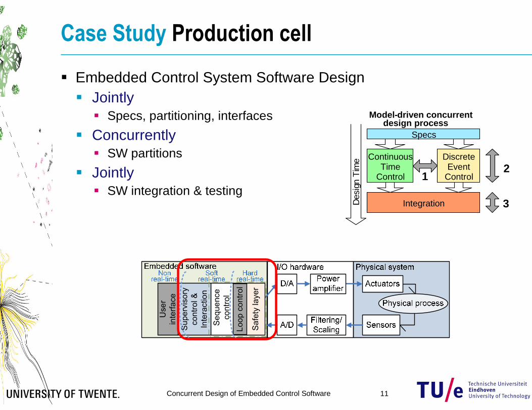
Case Study Production cell
� Embedded Control System Software Design� Jointly
� Specs, partitioning, interfaces
� Concurrently� SW partitions
� Jointly� SW integration & testing
ContinuousTime
Control
DiscreteEvent
Control
IntegrationDes
ign
Tim
e
Model-driven concurrent design process
1
3
2
Specs
User
interface
Supervisory
control &
Interaction
Sequence
control
Loop control
Safety layer

Concurrent Design of Embedded Control Software 12
Case Study Partitioning & Hierarchy
� Embedded Software� Discrete Event partition� Continuous/Discrete Time partition
� Based on� Top level system model� Production Cell Units (PCUs)
� Layered Software structure
� Interface
User
interface
Supervisory
control &
Interaction
Sequence
control
Loop control
Safety layer
CTCT/DTDE
CPU +
FPGA
Motor 150W
Gearhead 43:1
Encoder
Motor 150W
Gearhead 43:1
Encoder
Al
Extraction unit
Molderdoor
Feederunit
Feeder belt
Extraction belt
Rotation
unit
Motor 70W
Gearhead 18:1
Encoder
Motor 150W
Gearhead 15:1
Encoder
Magnet
Motor 150W
Gearhead 15:1
Encoder
Sensor
Extractionbuffer
Molderunit
Block movement direction
Embedded PC
Interface definitions

Concurrent Design of Embedded Control Software 13
Discrete Event Software Design
� Modeling tools : SHESim/Rotalumis� POOSL: Parallel Object-Oriented Specification Language� SHESim: Graphical tool for model construction and simulation� Rotalumis: Fast execution engine built in C++
� C-model : handshake diagram formalized in POOSL model� Partitions design into a set of concurrent actors� Actors synchronize action by a handshake sequence� Models untimed abstract interactions between actors

Concurrent Design of Embedded Control Software 14
Discrete Event Software Design
� M-model:� Refinement of C-model� Adds interfaces to low-level behavior� Focuses on interactions between high-level DE-control and
DT/CT loop control (MoC interaction)� Externally observable behavior is kept the same

Concurrent Design of Embedded Control Software 15
Discrete Event Software Design
� R-model: � Refinement of M-model� Adds low-level behavior � Both DT and DE behavior � Adds timing� Again, externally observable
functional behavior is kept the same
� Automatic code synthesis:� Automatic mapping to target platform� Property-preserving code generation� Building blocks with common interface � Mathematically proven timing relation
between model and implementation
Continuous()()
[ curstate = prestate ]
curstate := sensor Read;
delay 0.01;
Continuous()().
Discrete()()
sel
[ (curstate) & (prestate=false) ]
sensor ! on { prestate := curstate }
or
[ (prestate) & (curstate=false) ]
sensor ! off { prestate := curstate }
les;
Discrete()().
Concurrent Design of Embedded Control Software 16
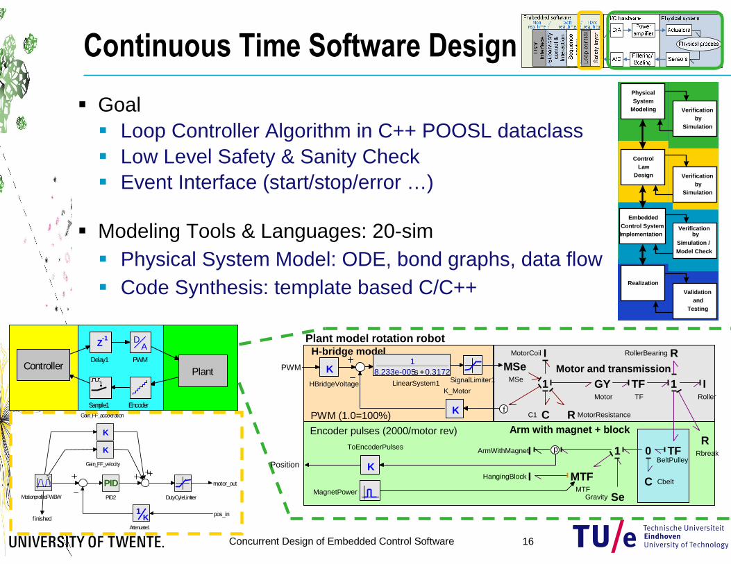
Continuous Time Software Design
� Goal� Loop Controller Algorithm in C++ POOSL dataclass� Low Level Safety & Sanity Check� Event Interface (start/stop/error …)
� Modeling Tools & Languages: 20-sim� Physical System Model: ODE, bond graphs, data flow� Code Synthesis: template based C/C++
Sample1 Encoder
Z-1
Delay1
PlantController
AD
PWM
PhysicalSystem
Modeling
ControlLaw
Design
EmbeddedControl SystemImplementation
Verificationby
Simulation / Model Check
Realization
Validationand
Testing
Verificationby
Simulation
Verificationby
Simulation
PhysicalSystem
Modeling
ControlLaw
Design
EmbeddedControl SystemImplementation
Verificationby
Simulation / Model Check
Realization
Validationand
Testing
Verificationby
Simulation
Verificationby
Simulation
PhysicalSystem
Modeling
ControlLaw
Design
EmbeddedControl SystemImplementation
Verificationby
Simulation / Model Check
Realization
Validationand
Testing
Verificationby
Simulation
Verificationby
Simulation
PhysicalSystem
Modeling
ControlLaw
Design
EmbeddedControl SystemImplementation
Verificationby
Simulation / Model Check
Realization
Validationand
Testing
Verificationby
Simulation
Verificationby
Simulation
pos_infinished
motor_out
MotionprofileFWBW
K1
Attenuate1
K
Gain_FF_velocity
K
Gain_FF_acceleration
PIDPID2 DutyCyleLimiter
H-bridge model
PWM (1.0=100%)
Encoder pulses (2000/motor rev) Arm with magnet + block
Plant model rotation robot
Motor and transmission
Position
PWM KHBridgeVoltage
K
K_Motor
18.233e-005s +0.3172
LinearSystem1 SignalLimiter1
K
ToEncoderPulses IArmWithMagnet
IRoller
RRollerBearing
TFTF
TFBeltPulley
C Cbelt
0
GYMotor
CC1
IMotorCoil
RRbreak
1
MSeMSe 1
R MotorResistance
1
IHangingBlock MTFMTF
p
MagnetPower SeGravity
f

Concurrent Design of Embedded Control Software 17
Continuous Time Software DesignControlled Motion Rotation Robot
0
0.1
0.2
0.3
0.4
Ref Position {m}
-5
0
5 Motor current {A}
-500
0
500 Rotation velocity {rad/s}
-0.5
0
0.5 PWM Output {x100%)
0
1
2
3 Real Pos {rad}
-0.0005
0
0.0005 Error {m}
0
0.5
1
1.5Forward Finished
0 0.5 1 1.5 2time {s}
0
0.5
1
1.5Backward Finished
class Controller_Rotation: public PooslDataClass{ /* the model functions */
void Initialize (double *u, double *y, double time);void Read (double *u, double *y);void Calculate (double *u, double *y, double time );void Write (double *u, double *y);void Terminate (double *u, double *y);
};
FPGAHW
DEsoftware
Loop +Safety
CPU +
FPGA
Motor 150W
Gearhead 43:1
Encoder
Motor 150W
Gearhead 43:1
Encoder
F
E
Extractionbuffer
Embedded PC
Concurrent Design of Embedded Control Software 18
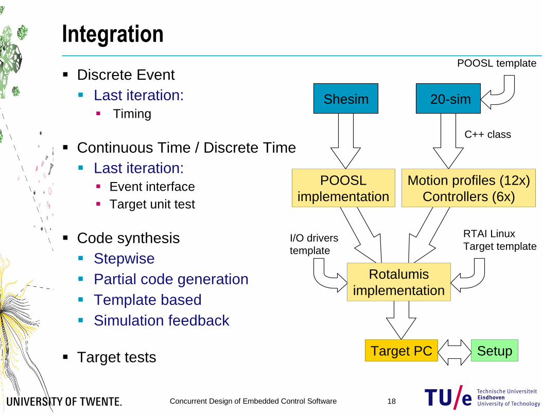
Integration
� Discrete Event� Last iteration:
� Timing
� Continuous Time / Discrete Time� Last iteration:
� Event interface� Target unit test
� Code synthesis� Stepwise� Partial code generation� Template based� Simulation feedback
� Target tests
Shesim 20-sim
C++ class
POOSL template
RTAI LinuxTarget template
Motion profiles (12x)Controllers (6x)
I/O driverstemplate
POOSLimplementation
Rotalumisimplementation
Target PC Setup

Concurrent Design of Embedded Control Software 19
Results & Discussion
� Short integration & testing phase� < 2 days, previous case: > week
� Almost running first time right� Minor timing issue with magnet on/off traction
delay� Concurrent, but separated design� Minimal information exchange
� Refinements on interfaces, data types, timing
� Required� Good partitioning� Building blocks approach
� Working setup

Concurrent Design of Embedded Control Software 20
Results Movie

Concurrent Design of Embedded Control Software 21
Results & Discussion
� Trade-off Concurrent Design � Integration� Minimal design interaction� Minimal information exchange
� Refinements on interfaces, data types, timing� Designers attitude
� Focus on own partition, but think across discipline boundaries
� Possible Improvements� Model-based integration tests
� Physical system model could be used to test the final software �Virtual Prototyping
� Tool support:� Automated consistency checks� Tool � Tool integration� Model � Model interaction
ContinuousTime
Control
DiscreteEvent
Control
IntegrationDes
ign
Ti m
e
Model-driven concurrent design process
1
3
2
Specs
ContinuousTime
Control
DiscreteEvent
Control
IntegrationDes
ign
Ti m
e
Model-driven concurrent design process
1
3
2
Specs

Concurrent Design of Embedded Control Software 22
Conclusions
� Mechatronics / Cyber Physical Systems� Synergistic design approach� Close cooperation between disciplines � integrated design
� Integrated design � concurrent design efficiency� Trade-off between early integration and late integration time� Choice is project specific
� Good partitioning of the mechatronic system� Allows concurrent, but partly separated design
� Case: fully integrated design is not always needed� More efficient work flow with still predictable integration
� Methodology not limited to SW implementation ECS� ECS in FPGA realization available

Concurrent Design of Embedded Control Software 23
Ongoing work
� Embedded Control System software for our Humanoid Soccer Robot� Vision processing� Supervisory control� Sequence control� Path planning� Soccer strategy� Low level loop control
� 24 degrees of freedom