concrete pumps - multiquip inc.€¦ · n priority one truck n ground n next day ... this manual to...
TRANSCRIPT

OPERATION AND PARTS MANUAL
THIS MANUAL MUST ACCOMPANY THE EQUIPMENT AT ALL TIMES.
To find the latest revision of thispublication, visit our website at:
www.multiquip.com
SERIESMODELS LS400/LS500
CONCRETE PUMPS(DEUTZ F4L2011, BF4L2011 DIESEL ENGINES)
Revision #6 (09/19/11)

PAGE 2 — MAYCO LS400/LS500 PUMP — OPERATION AND PARTS MANUAL — REV. #6 (09/19/11)
Proposition 65 Warning
Diesel engine exhaust and some of
LS400/LS500 PUMP — PROPOSITION 65 WARNING

MAYCO LS400/LS500 PUMP — OPERATION AND PARTS MANUAL — REV. #6 (09/19/11) — PAGE 3
NOTES

PAGE 4 — MAYCO LS400/LS500 PUMP — OPERATION AND PARTS MANUAL — REV. #6 (09/19/11)
LS400/LS500 PUMP —TABLE OF CONTENTS
Specification and part number are subjectto change without notice.
MAYCO LS400/LS500CONCRETE PUMPSProposition 65 Warning ............................................. 2Table of Contents ...................................................... 4Parts Ordering Procedures ...................................... 5Safety Message Alert Symbols ..............................6-7Rules for Safe Operation .....................................8-10Specifications .......................................................... 12Dimensions ............................................................. 13Important Hand Signals .......................................... 14General Information ...........................................15-16How it Works ........................................................... 17Pump Components ............................................18-19Digital Control Panel Components .......................... 20Digital Readout Screen ........................................... 21Engine Components ............................................... 22Inspection ...........................................................23-25Set-Up ..................................................................... 26Start-Up Procedure ................................................. 27Operation ...........................................................28-31Pumping Information ..........................................32-35Maintenance (Pump) .........................................36-43Maintenance (Trailer) .........................................44-46Trailer Safety Guidelines ....................................47-61Troubleshooting (Pump).....................................62-64Troubleshooting (Engine) ........................................ 65Troubleshooting (Brake System)............................. 66Troubleshooting (Electrical) ...............................67-69Wiring Diagram (Control Box) ............................70-73Wiring Diagram (Optional Hopper Vibrator) ............ 74Hydraulic System Diagram ..................................... 75Manifold Block Ports ............................................... 76Appendix - Concrete Mix Information ................77-78Appendix - Slump Test Procedure........................... 79Appendix - Recommended Shotcrete System ...... 80-81Appendix - Recommended Shotcrete Accessories .... 82-83Explanation Of Codes In Remarks Column ............ 84Suggested Spare Parts ........................................... 85
COMPONENT DRACOMPONENT DRACOMPONENT DRACOMPONENT DRACOMPONENT DRAWINGSWINGSWINGSWINGSWINGSName Plate and Decals ..................................... 86-89Frame Assy. ....................................................... 90-91Axle Assy. ........................................................... 92-93Brake Line Assy. ................................................ 94-95Brake Lights Assy. .............................................. 96-97Trailer Hitch Assy. ............................................... 98-99Battery Assy. .................................................. 100-101Hopper Assy. .................................................. 102-103Hopper Attachment Assy. .............................. 104-105Hopper Interior Assy. ..................................... 106-107Shuttle Cylinder Assy. .................................... 108-109Lubrication Pistons Assy. ............................... 110-111Fuel Tank Assy. .............................................. 112-115Heat Exchanger Assy. .................................... 116-117Accumulator Assy. .......................................... 118-119Remixer Control Assy. .................................... 120-121Lubrication Panel Assy. .................................. 122-123Engine Cover Assy. ........................................ 124-125Hydraulic Tank Assy. ...................................... 126-127Engine Assy. ................................................... 128-129Throttle Assy. ................................................. 130-131Water Separator Assy. ................................... 132-133Hydraulic Pump Assy. .................................... 134-135Manifold Assy. ................................................ 136-137Control Box Assy. ........................................... 138-139Control Box Harness Assy. ............................ 140-141Remote Control Cable Assy. .......................... 142-143Hydraulic Stabilizer Assy. (Optional) .............. 144-145
Terms and Conditions of Sale - Parts ................... 146Mayco Pump Warranty .......................................... 147

MAYCO LS400/LS500 PUMP — OPERATION AND PARTS MANUAL — REV. #6 (09/19/11) — PAGE 5
ww
w.m
ultiq
uip
.com
Ordering parts has never been easier! Choose from three easy options:
WE ACCEPT ALL MAJOR CREDIT CARDS!
When ordering parts, please supply: Dealer Account Number Dealer Name and Address Shipping Address (if different than billing address) Return Fax Number Applicable Model Number Quantity, Part Number and Description of Each Part
Specify Preferred Method of Shipment:UPS/Fed Ex DHL
Priority One Truck Ground
Next Day Second/Third Day
If you have an MQ Account, to obtain a Username and Password, E-mail us at: [email protected].
To obtain an MQ Account, contact your District Sales Manager for more information.
Order via Internet (Dealers Only):Order parts on-line using Multiquip’s SmartEquip website! View Parts Diagrams Order Parts Print Specification Information
Note: Discounts Are Subject To Change
Goto www.multiquip.com and click on Order Parts to log in and save!
Use the internet and qualify for a 5% Discount on Standard orders for all orders which include complete part numbers.*
Order via Fax (Dealers Only):All customers are welcome to order parts via Fax.Domestic (US) Customers dial: 1-800-6-PARTS-7 (800-672-7877)
Fax your order in and qualify for a 2% Discount on Standard orders for all orders which include complete part numbers.*
Order via Phone: Domestic (US) Dealers Call: 1-800-427-1244
Best Deal!
International Customers should contact their local Multiquip Representatives for Parts Ordering information.
Non-Dealer Customers: Contact your local Multiquip Dealer for parts or call 800-427-1244 for help in locating a dealer near you.
Note: Discounts Are Subject To Change
Effective: January 1st, 2006
NOTICE
All orders are treated as Standard Orders and will ship the same day if received prior to 3PM PST.
PARTS ORDERING PROCEDURES

PAGE 6 — MAYCO LS400/LS500 PUMP — OPERATION AND PARTS MANUAL — REV. #6 (09/19/11)
Safety precautions should be followed at all times whenoperating this equipment. Failure to read and understandthe Safety Messages and Operating Instructions could resultin injury to yourself and others.
FOR YOUR SAFETY AND THE SAFETY OF OTHERS!
This Owner's Manual has been developedto provide complete instructions for the safeand efficient operation of the MultiquipMayco LS400/LS500 Concrete pump. Referto the engine manufacturers instructions fordata relative to its safe operation.
Before using this pump , ensure that the operatingindividual has read and understands all instructions inthis manual.
SAFETY MESSAGE ALERT SYMBOLS
The three (3) Safety Messages shown below will inform youabout potential hazards that could injure you or others. TheSafety Messages specifically address the level of exposureto the operator, and are preceded by one of three words:DANGER, WARNING, or CAUTION.
You WILL be KILLED or SERIOUSLY injured if youdo not follow directions.
You COULD be KILLED or SERIOUSLY injured ifyou do not follow directions.
You CAN be injured if you do not follow directions
HAZARD SYMBOLS
Diesel engine exhaust gases containpoisonous carbon monoxide. This gasis colorless and odorless, and cancause death if inhaled. NEVERoperate this equipment in a confinedarea or enclosed structure that doesnot provide ample free flow air.
Potential hazards associated with operation of the pump willbe referenced with Hazard Symbols which appear throughoutthis manual, and will be referenced in conjunction with SafetyMessage Alert Symbols. Some examples are listed below:
Diesel fuel is extremely flammable, andits vapors can cause an explosion ifignited. DO NOT start the engine nearspilled fuel or combustible fluids. DONOT fill the fuel tank while the engine
is running or hot.
DO NOT overfill tank, since spilled fuel could ignite if itcomes into contact with hot engine parts or sparks fromthe ignition system. Store fuel in approved containers,in well-ventilated areas and away from sparks andflames. NEVER use fuel as a cleaning agent.
Engine components can generateextreme heat. To prevent burns, DO NOTtouch these areas while the engine isrunning or immediately after operations.NEVER operate the engine with heatshields or heat guards removed.
LS400/LS500 PUMP — SAFETY MESSAGE ALERT SYMBOLS
WARNING
DANGER
CAUTION
WARNING - LETHAL EXHAUST GASES
WARNING - BURN HAZARDS
WARNING - EXPLOSIVE FUEL

MAYCO LS400/LS500 PUMP — OPERATION AND PARTS MANUAL — REV. #6 (09/19/11) — PAGE 7
ALWAYS place the Engine ON/OFFswitch in the OFF position. NEVERperform maintenance on the unit withthe ignition key in the ON position.
ALWAYS wear approved respiratoryprotection.
This machine is capable ofproducing noise levels above 85 dB.Hearing protection is required.Always wear eye protection.
LS400/LS500 PUMP — SAFETY MESSAGE ALERT SYMBOLS
Other important messages are provided throughoutthis manual to help prevent damage to your concretepump, other property, or the surrounding environment.
This pump, other proper ty, or thesurrounding environment could be damagedif you do not follow instructions.
NEVER tamper with the factorysettings of the engine governor orsettings. Personal injury and damageto the engine or equipment can resultif operating in speed ranges abovemaximum allowable.
CAUTION - OVER-SPEED CONDITIONS
CAUTION - ACCIDENTAL STARTING
CAUTION - RESPIRATORY HAZARDS
CAUTION - SIGHT AND HEARING HAZARDS
CAUTION - EQUIPMENT DAMAGE MESSAGES
NEVER operate equipment with covers,or guards removed. Keep fingers,hands, hair and clothing away from allmoving parts to prevent injury.
WARNING - ROTATING PARTS

PAGE 8 — MAYCO LS400/LS500 PUMP — OPERATION AND PARTS MANUAL — REV. #6 (09/19/11)
The following safety guidelines should always be used whenoperating the LS400/LS500 concrete pump:
GENERAL SAFETY
■ DO NOT operate or service thisequipment before reading this entiremanual.
■ NEVER touch the hot exhaust manifold, muffleror cylinder. Allow these parts to cool beforeservicing engine or pump.
■ High Temperatures – Allow the engineto cool before adding fuel or performingservice and maintenance functions.Contact with hot! components cancause serious burns.
■ The engine section of thispump requires anadequate free flow ofcooling air. NEVERoperate the pump in anyenclosed or narrow areawhere free flow of the airis restricted. If the air flow is restricted it will cause seriousdamage to the pump or engine and may cause injury topeople. Remember the pump's engine gives off DEADLYcarbon monoxide gas.
■ ALWAYS refuel in a well-ventilated area, away from sparksand open flames.
■ ALWAYS use extreme caution whenworking with flammable liquids. Whenrefueling, stop the engine and allow it tocool.
■ NEVER smoke around or near themachine. Fire or explosion could result fromfuel vapors, or if fuel is spilled on a hot!engine.
■ NEVER operate the pump in an explosive atmosphere ornear combustible materials. An explosion or fire couldresult causing severe bodily harm or even death.
■ Topping-off to filler port is dangerous, as it tends to spillfuel.
■ ALWAYS remove the ignition key when leaving the pumpunattended.
■ ALWAYS block the wheels on the unit when using on aslope.
■ ALWAYS maintain this equipment in a safe operatingcondition at all times.
■ ALWAYS stop the engine before servicing, adding fuel oroil.
LS400/LS500 PUMP — RULES FOR SAFE OPERATION
■ ALWAYS check the machine for loosened threads or boltsbefore starting.
■ ALWAYS wear proper respiratory (mask), hearing andeye protection equipment when operating the pump.
■ Whenever necessary, replace nameplate, operation andsafety decals when they become difficult read.
■ Manufacture does not assume responsibility for anyaccident due to equipment modifications.
■ NEVER use accessories or attachments, which are notrecommended by Multiquip for this equipment. Damageto the equipment and/or injury to user may result.
■ NEVER operate this equipment when not feelingwell due to fatigue, illness or taking medicine.
■ NEVER operate this equipment under theinfluence or drugs or alcohol.
■ This equipment should not beoperated by persons under 18 yearsof age.
■ NEVER operate this equipment without proper protectiveclothing, shatterproof glasses, steel-toed boots and otherprotective devices required by the job.
DANGER - READ OPERATION AND PARTS
Failure to follow instructions in this manual may lead toserious injury or even death! This equipment is to beoperated by trained and qualified personnel only! Thisequipment is for industrial use only.

MAYCO LS400/LS500 PUMP — OPERATION AND PARTS MANUAL — REV. #6 (09/19/11) — PAGE 9
■ NEVER run engine without air filter. Severe enginedamage may occur.
■ ALWAYS be sure the operator is familiar with proper safetyprecautions and operation techniques before using pump.
■ ALWAYS store equipment properly when it is not beingused. Equipment should be stored in a clean, dry locationout of the reach of children.
■ DO NOT operate this equipment unless the hopper grate,guards and safety devices are attached and in place.
■ CAUTION must be exercised while servicing thisequipment. Rotating and moving parts can cause injuryif contacted.
■ Keep all inexperienced and unauthorized people awayfrom the equipment at all times.
■ Before start-up, check the hopper and remove all foreignmatter and debris.
■ DO NOT use worn or damaged hose couplings, inspectall hoses and couplings for wear. Replace any worn ordefective hose or couplings immediately.
■ Keep hands out of the hopper when the engine is running.■ DO NOT disconnect hose couplings or nozzle while under
pressure. Relieve pressure by activating the reversefunction switch located on the control panel.
■ Unauthorized equipment modifications will void allwarranties.
■ Check all fasteners periodically for tightness. Also checktowing tongue bolt, lock nut and wheel lug nuts for wear.
■ Test the pump's ON/OFF switch. The purpose of thistest is to shut down the engine.
■ Refer to the DEUTZ Engine Owner's Manual for enginetechnical questions or information recommended byMultiquip for this equipment. Damage to the equipmentand or injury to user may result.
■ Always use properly rated hoses and clamps — 1500PSI and higher.
TRANSPORTING
■ ALWAYS shutdown engine before transporting the pump.
■ Tighten fuel tank cap securely to prevent fuel fromspilling.
■ Drain fuel when transporting pump over long distancesor bad roads.
Towing■ Before towing, check the hitch and secure the safety
chain to the towing vehicle.
■ When towing, an adequate safety chain must be fastenedto the frame, refer to Towing Guidelines.
■ Tow only with a vehicle and hitch rated to pull a 6,000lbs. load.
■ If unit is equipped with ball hitch coupler, use only 2" allsteel ball rated for minimum of 6,000 lbs. Use 1" hardenedsteel pull pin, if not equipped with ball hitch.
■ This equipment shall not be towed or operated byindividuals who cannot read understand the signs, decalsor operating instructions.
■ When towing at night, always have rear tail lights ON.
■ DO NOT tow unit with hopper full of material.
■ DO NOT tow unit with hoses attached.
■ DO NOT tow unit in excess of 55 MPH on highways.
LS400/LS500 PUMP — RULES FOR SAFE OPERATION
PAGE 10 — MAYCO LS400/LS500 PUMP — OPERATION AND PARTS MANUAL — REV. #6 (09/19/11)
LS400/LS500 PUMP — RULES FOR SAFE OPERATION
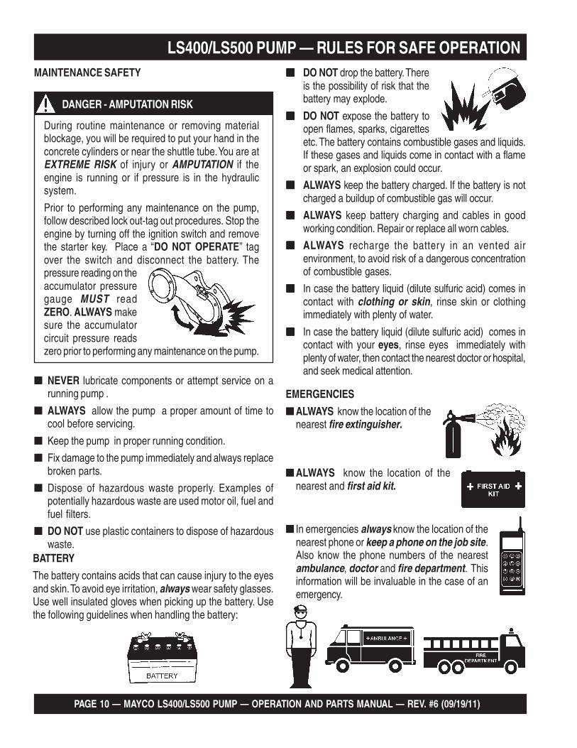
EMERGENCIES
■ ALWAYS know the location of thenearest fire extinguisher.
■ ALWAYS know the location of thenearest and first aid kit.
■ In emergencies always know the location of thenearest phone or keep a phone on the job site.Also know the phone numbers of the nearestambulance, doctor and fire department. Thisinformation will be invaluable in the case of anemergency.
BATTERY
The battery contains acids that can cause injury to the eyesand skin. To avoid eye irritation, always wear safety glasses.Use well insulated gloves when picking up the battery. Usethe following guidelines when handling the battery:
■■■■■ DO NOT drop the battery. Thereis the possibility of risk that thebattery may explode.
■■■■■ DO NOT expose the battery toopen flames, sparks, cigarettesetc. The battery contains combustible gases and liquids.If these gases and liquids come in contact with a flameor spark, an explosion could occur.
■■■■■ ALWAYS keep the battery charged. If the battery is notcharged a buildup of combustible gas will occur.
■■■■■ ALWAYS keep battery charging and cables in goodworking condition. Repair or replace all worn cables.
■■■■■ ALWAYS recharge the battery in an vented airenvironment, to avoid risk of a dangerous concentrationof combustible gases.
■■■■■ In case the battery liquid (dilute sulfuric acid) comes incontact with clothing or skin, rinse skin or clothingimmediately with plenty of water.
■■■■■ In case the battery liquid (dilute sulfuric acid) comes incontact with your eyes, rinse eyes immediately withplenty of water, then contact the nearest doctor or hospital,and seek medical attention.
MAINTENANCE SAFETY
■ NEVER lubricate components or attempt service on arunning pump .
■ ALWAYS allow the pump a proper amount of time tocool before servicing.
■ Keep the pump in proper running condition.
■ Fix damage to the pump immediately and always replacebroken parts.
■ Dispose of hazardous waste properly. Examples ofpotentially hazardous waste are used motor oil, fuel andfuel filters.
■ DO NOT use plastic containers to dispose of hazardouswaste.
During routine maintenance or removing materialblockage, you will be required to put your hand in theconcrete cylinders or near the shuttle tube. You are atEXTREME RISK of injury or AMPUTATION if theengine is running or if pressure is in the hydraulicsystem.
Prior to performing any maintenance on the pump,follow described lock out-tag out procedures. Stop theengine by turning off the ignition switch and removethe starter key. Place a “DO NOT OPERATE” tagover the switch and disconnect the battery. Thepressure reading on theaccumulator pressuregauge MUST readZERO. ALWAYS makesure the accumulatorcircuit pressure readszero prior to performing any maintenance on the pump.
DANGER - AMPUTATION RISK

MAYCO LS400/LS500 PUMP — OPERATION AND PARTS MANUAL — REV. #6 (09/19/11) — PAGE 11
NOTES

PAGE 12 — MAYCO LS400/LS500 PUMP — OPERATION AND PARTS MANUAL — REV. #6 (09/19/11)
.2ELBAT SNOITACIFICEPSENIGNE
ledoMF1102L4FztueD
enignEleseiDF1102L4FBztueD
enignEleseiD
epyT leseiDdelooc-riA,ekorts4
srednilyCfo.oN 4
ekortSxeroB.ni5x.ni91.4
)mm721xmm601(
tuptuOdetaR mpr0003@PH06 mpr0003@PH97
tnemecalpsiD )L37.2(.ni.uc761
gnitratS CDV21cirtcelE
yticapaCliOebuL )sretil5.2(.lag5.9
epyTleuF leuFleseiD2#
yrettaB 72puorGVCDV21
LS400/LS500 PUMP — SPECIFICATIONS
SNOITACIFICEPSPMUP.1ELBAT
ledoM 004-SL 005-SL
etaRgnipmuP.uc04otpU*ruohrep.sdy
.uc05otpU*ruohrep.sdy
dohteMgnipmuP notsiPgnitacorpiceR
eziSetagerggAmumixaM )mm83(sunim.ni2/1-1
thgieHgnipmuPlacitreV )m67(.tf052fossecxEotpU
erusserPecaFnotsiP isp0511
ecnatsiDgnipmuPlatnoziroH *)m503(.tf0001
yticapaCxoBnoitacirbuLrednilyC )sretiL6.7(snollaG2
yticapaCdiulFciluardyH )sretiL981(snollaG05
yticapaCknaTleuF )sretiL67(snollaG04
yticapaCreppoH reximerver/dwflanoitpohtiw.tf.uc01
esoHlairetaM.aid.ni5,.ni4,.ni3
)mm721,mm6.101,mm2.67(
ledoMenignEleseiDztueD
1102L4FobruTztueD
1102L4FBleseiD
)sdiulfhtiw(thgieW )gk951,2(.sbl067,4
)gnippihs/yrd(thgieW )gk860,2(.sbl065,4
eziSeriT )mm653xmm781(.ni41x.ni53.7
snoitpO,rotarbiVneercSreppoH,lortnoCetomeRsseleriW
rezilibatSraeRciluardyH
snotitidnocetisbojdnadesuezisenil,pmuls,ngisedximnognidnepedyravlliwtuptuoemuloV*

MAYCO LS400/LS500 PUMP — OPERATION AND PARTS MANUAL — REV. #6 (09/19/11) — PAGE 13
LS400/LS500 PUMP — DIMENSIONS
SNOISNEMID.3ELBAT
.FER SNOISNEMID
A ).mc2.901(.ni34
B ).mc734(.ni271
C ).mc16(.ni42
D ).mc8.771(.ni07
E ).mc2.271(.ni86
Figure 1. Dimensions

PAGE 14 — MAYCO LS400/LS500 PUMP — OPERATION AND PARTS MANUAL — REV. #6 (09/19/11)
LS400/LS500 PUMP — IMPORTANT HAND SIGNALS
Figure 2. Operation Hand Signals
Figure 2 displays the basic hand signals commonly used in concrete pumping operations.
MAYCO LS400/LS500 PUMP — OPERATION AND PARTS MANUAL — REV. #6 (09/19/11) — PAGE 15
CONCRETE MIX DESIGN
Mix design is most important to achieve maximum pumpability.Pumpability is affected by, among other factors, the type andgradation of aggregate used. Natural aggregates make a moreworkable mix and pump more readily than crushed aggregates.A blend of natural and crushed aggregates will produce aworkable mix. The type and gradation of aggregates is equallyimportant for workability as the size and percentage of coarseaggregates in the mix.
The term “aggregates” describes all of the solid materials, fromthe largest rock to the smallest grain of sand, contained in theconcrete mix.
Concrete mixes with a consistency as dry as one-inch slumpand as wet as ten-inch slump have been pumped; but formaximum efficiency from the pump, a slump ranging from two tosix inches will produce a more workable mix than one thatcontains more or less water.
The principle of concrete pumping is based on self-lubrication.As it moves through the transfer line, the concrete takes theshape of a plastic cylinder. It is forced through the transfer line ona film of mortar that is self-troweled to the service of the transferline around its full periphery by the slug of concrete itself.
A slump rating should be used with discretion; it is not always areal indication of the pumpability of the mix. The concrete maybe workable in the sense that it will readily flow into place, butthe same mix may not respond to pressure. Overly wet mixestend to separate. In addition to affecting the strength and qualityof the concrete, the delivery system will not tolerate separation.Overly dry mixes are similarly unsatisfactory if they lack plasticityand tend to be crumbly. To be properly pumped, the mix must beable to continuously coat the inside of the line with a lubricatingseal of mortar.
LS400/LS500 PUMP — GENERAL INFORMATIONThere are four ways in which this seal can be lost:
1. By pumping excessively wet mixes which do not haveenough cohesion to hold together.
2. By pumping harsh undersanded concrete with poorly gradedaggregates which can jam together when the pressurebecomes too great for the insufficient amount of sand tohold the aggregates apart.
3. By getting a rock pocket, such as mixer tailings, into thepump valve. This rock pocket will have an insufficient coatingof mortar and the mix will not be plastic enough to allow thevalve to operate or the mix to move in the line.
4. Through excessive bleeding. If the mix is short or fines, butthe sand is otherwise fairly well graded, bleeding will notnormally create any problems as long as the pump continuesoperation. But, if the pump is shut down, bleeding can resultin a loss of lubrication and blocked erratic flow.
The above are bad concrete practices, regardless of how themix is to be placed. But, these points do show that special mixesare not always needed, within limits, for pumping concrete. Goodaggregate gradation is most important to pump concrete themaximum distance.
The use of admixtures can have a beneficial effect on pumpability.Most of the dispersing agents will fatten, retard bleeding, andincrease workability. Thus, the average concrete can be pumpedfor appreciably longer distances. Air entraining agents will alsoimprove workability, although they cannot be used as a substitutefor good gradation of the aggregate. Pumping will not appreciablyaffect the final air content of the mix. High-early cement tends togive a more readily pumpable mix with superior water retainingqualities. However, if delays are likely to occur, extra care mustbe exercised due to the faster setting time over regular cement.
The Mayco LS400/LS500 models will pump a wide variety ofconcrete pump mixes. But, there are guidelines that must befollowed. Use this information in conjunction with the Operationsection of this manual.

PAGE 16 — MAYCO LS400/LS500 PUMP — OPERATION AND PARTS MANUAL — REV. #6 (09/19/11)
LS400/LS500 PUMP — GENERAL INFORMATIONREGIONAL DIFFERENCES
Concrete is made by mixing locally available rock and sand withcement and water. For this reason there are great differences inthe pumpability of concrete from one region of the country toanother.
It is impossible to define a specific mix for each region that theconcrete pump be will working in. Therefore, the mixes listed inAppendix - Concrete Mix Information will provide a basicguideline for establishing the proper mix design for your area.
Use this information to specify your requirements to your localready-mix batch plant, contractor and civil engineer. It may takeminor adjustments to make a mix pumpable, so you shouldexplain your needs.
The elements that have to be controlled and consistentlymaintained by the batch plant are:
1. The sizing and mix percentage of rocks, gap graded fromthe largest down through the smallest sizes.
2. Sand with a sieve analysis that has the proper percentageof fines, ASTM C33 spec.
3. Sufficient cement to produce the required design strengthof the concrete and provide the lubricating binder to pumpthe concrete through the delivery system.
Use a minimum of:
500 lbs. of cement/cu yd for 2500 p.s.i. concrete after 28days.
530 lbs. of cement/cu yd for 3000 p.s.i. concrete after 28days.
600 lbs. of cement/cu yd for 4000 p.s.i. concrete after 28days.
4. Admixture pump-aid if necessary.
5. The proper amount of water to make a workable slump andplasticize the mix.
In addition, this Mayco Concrete Pump can be used to pump alarge aggregate hard rock as follows:
1. Pea rock (1/2" minus) pump with mixes being as low as 30%rock and 70% sand. (See page 44, for comments on cleaningthe pump.)
2. Shortening pea rock when used with an air compressorand nozzle. (See back pages for recommended setup.)
3. “Mud Jacking”, high pressure grouting.

MAYCO LS400/LS500 PUMP — OPERATION AND PARTS MANUAL — REV. #6 (09/19/11) — PAGE 17
LS400/LS500 PUMP — HOW IT WORKSThe following is a brief explanation of how the concrete cylinders,hydraulic cylinders, shuttle tube, valves and hopper work insequence to pump concrete.
The hydraulic pressure is generated by a variable volume,pressure compensated, axial piston pump that is driven by adiesel engine. The rod sides of the drive cylinders arehydraulically connected together creating a “slave circuit,” whichallows hydraulic oil to transfer from one piston to the other.
The two part cycling sequence is initiated by an electrical signalgenerated by two proximity switches activated by the drivecylinder. The proximity switches are normally open, magneticallysensing the movement of the main drive cylinder. As the drivecylinder piston head passes the proximity switch, an electricalsignal is sent to the solenoid operated pilot valve which in turndirects pilot oil to the four valves controlling the drive cylinderand the shuttle cylinder.
A one-gallon accumulator assists the movement of the shuttletube. This circuit assures that the shuttle tube will throw with thesame intensity of each stroke regardless of how fast the maindrive cylinders are cycling.
Figure 3. Pumping Cycle 1
TO TANKHIGH PRESSUREOIL FROM PUMP
PROXIMITYSWITCHHYDRAULIC
CYLINDERS
PISTONCUP
CONCRETECYLINDERS
SHUTTLE TUBE
SLAVE
OIL
SHUTTLE TUBE MOTION
A
B
In the first cycle, hydraulic pressure is applied to cylinder (B),causing the hydraulic piston, which is connected to the concretepiston and piston cup, to discharge concrete into the deliveryline (Figure 3).
As one cylinder is discharging concrete, the hydraulic oil fromthe rod side (B) of the drive cylinders is being transferred throughthe slave circuit causing the opposite cylinder (A) to move backon the suction stroke, filling the cylinder with concrete.
The shuttle tube is sequenced to pivot to each concrete cylinderas the drive cylinders stroke to push concrete. As the secondcycling sequence begins (Figure 4), the shuttle tube pivots tothe opposite cylinder (A). The hydraulic piston passes under theproximity switch and sends pressure to the piston, causing it tostroke and discharge concrete into the delivery line. Hydraulicoil is transferred through the slave circuit to cylinder B, causing itto start a suction stroke, refilling it with concrete. The pumpingsequence then repeats for the duration of the operation.
Figure 4. Pumping Cycle 2

PAGE 18 — MAYCO LS400/LS500 PUMP — OPERATION AND PARTS MANUAL — REV. #6 (09/19/11)
LS400/LS500 PUMP — PUMP COMPONENTS
Figure 5. Major Pump Components

MAYCO LS400/LS500 PUMP — OPERATION AND PARTS MANUAL — REV. #6 (09/19/11) — PAGE 19
LS400/LS500 PUMP — PUMP COMPONENTSFigure 5 illustrates the location of the major components forthe LS400/LS500 Concrete Pump. The function of eachcomponent is described below:1. Tow Hitch Coupler – Requires a 2-inch ball hitch or a
3-inch pintle. Capable of towing 6,000 lbs.2. Documentation Box – Contains engine and pump
operation, parts and maintenance information.3. Manifold Access Door– Release latch and lift door to
access the Hydraulic Manifold Block.4. Hydraulic Manifold Block – Manifold block that
controls the flow of hydraulic pressure to thecomponents required to control the pump.
5. Hopper Discharge Sleeve – Connect hoses or steelpipes to the discharge sleeve for pouring concrete.
6. Pump End Jack Stand – Use this jack stand to leveland support the rear end of the pump. NEVER deployon un-level ground and always check for firmness ofground.
7. Shuttle Cylinder – Under pressure, the shuttle cylindershears concrete passing from the concrete cylinder tothe delivery line during the cycle phase.
8. Tires — This trailer uses two ST205-750 x15E typetires. Tire inflation pressure is the most important factorin tire life. Pressure should be checked to 50 psi coldbefore operation. DO NOT bleed air from tires whenthey are hot. Check inflation pressure weekly duringuse to insure the maximum tire life and tread wear.
9. Battery – This unit uses a +12 VDC type battery.ALWAYS use gloves and eye protection when handlingthe battery.
10. Hydraulic Pump – This unit incorporates an axialvariable displacement hydraulic piston pump.
11. Heat Exchanger – Reduces temperature of thehydraulic oil. The exchanger draws oil from the hydraulictank through a filter and into the heat exchanger beforeallowing it to flow into the hydraulic system.
12. Accumulator – Stores hydraulic oil under pressure andreleases it to the shuttle cylinder and provides thepressure needed to ensure enough force is providedduring cycle.
13. Remixer Control Lever – Controls the forward/reversemotion of the hopper remixer paddles.
14. Hydraulic Oil Sight Glass – Use to determine theamount of hydraulic oil remaining in tank. The sightglass also contains a temperature gauge for monitoringthe temperature of the hydraulic oil.
15. Hydraulic Oil Tank/Cap– Remove cap to add hydraulicfluid. Fill with Shell Oil Tellus 68 or Mobil Oil DFE26 iflevel is low.
16. Accumulator Pressure Gauge– Used to monitoraccumulator pressure. Pressure should read at least1750 psi for correct pump operation.
17. Pumping Pressure Gauge – Used to monitor pressurein the concrete cylinders and shuttle tube.
18. Control Box – Contains the electrical componentsrequired to run the pump. See Control Box Componentssection for component callouts.
19. Fuel Tank/Cap – Fill with diesel fuel. Fuel tank (cell)holds approximately 40 gallons (176 liters). DO NOTtop off fuel. Wipe up any spilled fuel immediately.
20. Hydraulic Oil Filter – This in-tank return hydraulicfilter with a 10 micron cleanable filter is designed toremove all particles large enough to cause wear andjob break down. Under normal conditions, replace every6 months.
21 Lubrication Box – This box is empty when shippedfrom the factory. Please fill with 3 gallons (11.35 liters)of SAE 30 motor oil for first time use. Also check thedual clean-out point on bottom of lubrication box for asecure tight fit.
22. Rear Running Lights – ALWAYS check and makesure both the right and left running lights are functioningcorrectly before towing the pump.
23. Remixer Motor – Drives the remixer paddles insidethe hopper. The motor direction is controlled by theremixer control lever.
24. Hopper/Hood – Lift hood to fill. Concrete from a Redi-Mix truck is poured into this hopper. The hopper canhold 10 cu. ft of concrete with optional forward/reversemixer. NEVER put hands or any other parts of you bodyinto the hopper.
25. Tow End Jack Stand – Use this jack stand to leveland support the tow end of the pump.

PAGE 20 — MAYCO LS400/LS500 PUMP — OPERATION AND PARTS MANUAL — REV. #6 (09/19/11)
LS400/LS500 PUMP — DIGITAL CONTROL PANEL COMPONENTS
Figure 6. Pump Digital Control Panel Components
1. Emergency Stop Button – Press emergency stopbutton to stop pump in an emergency. Turn knobcounterclockwise to disengage the stop button.
2. Ignition Switch – Insert the ignition key here to startthe engine. Turn the key clockwise to the ON position,then continue turning clockwise to the START positionand release. To stop the engine turn the key fullycounterclockwise to the STOP position.
3. Digital Readout Screen – Displays and monitors thevarious functions of the machine.
4. Scroll Switch – Allows the operator to scroll the variousreadout screens.
5. Reset Switch – Allows the operator to reset the strokecounter.
6. Remote Cable Connector – Insert the remote controlinput cable into this connector.
7. Direction Control Switch – This 2-position switchcontrols the direction of flow for any mix in the pump.The leftmost position sets the pumping direction toforward and the rightmost position sets the pumpingdirection to reverse.
8. Pumping Control Switch – This 3-position switchcontrols the pumping of the pump. The rightmostposition (REMOTE) is for use with the remote controlunit, the leftmost position (LOCAL) is for normalpumping operation, and the centermost position(CENTER OFF) prevents pumping.
9. Cylinder Stroke Control Switch – This 2-positionswitch controls the pumping function. The leftmostposition (AUTOMATIC) sets the pump to automaticcycling. Set the switch to this position for normal pumpoperation.The rightmost position (JOG) changes the pump fromautomatic to manual cycling. This allows the cylindersto be manually cycled using the Manual CylinderJogging Switch.
10. Manual Cylinder Jogging Switch – This 2-positionswitch allows the operator to manually jog the cylindersto assist in clearing material line packs and is used totest pumping pressure (See Initial Start-up Proceduresection of this manual for testing procedure).The leftmost position jogs Cylinder “A” and therightmost position jogs Cylinder “B”.
11. Stroke Volume Control Switch – Increases ordecreases the number of strokes per minute of thepump.
12. Accumulator Pressure Gauge – This gauge monitorsthe internal pressure of the Accumulator tank. Normalinternal pressure should read approximately 1750 PSIduring pumping.
13. Main Pressure Gauge – This gauge monitors thesystem pressure while pumping material. The maximumpressure rating is 4400 PSI ± 50.
0
50
0
750
1000
1250
150
02000
0
50
0
750
1000
1250
150
02000
E
MERGENCY STO
P
ACCUMULATORPRESSURE
PUMPINGPRESSURE
1
2
4
5
6109
7
3
8
12
11
13
OFFON
IGNITION
REMOTE
CONTROLFLOW
DIRECTION
VOLUME
LOCALFORWARD
AUTOMATIC JOG
RESET
SET
DECREASE INCREASE
SCROLL
JOG “A”
CYLINDER STROKE
JOG “B”
REVERSE
CENTEROFF
REMOTE
START

MAYCO LS400/LS500 PUMP — OPERATION AND PARTS MANUAL — REV. #6 (09/19/11) — PAGE 21
LS400/LS500 PUMP — DIGITAL READOUT SCREENPRIMARY SCREEN
Screen 1Indicates the various modes of the switch settings.Monitors engine RPM - Idle speed 900, High speed 2550.Battery charge indicator - Normal charge 13+ volts.Indicates electrical malfunction - Refer to Troubleshootingsection.
SECONDARY SCREENS
Screen 2Displays the position of the VOLUME CONTROL switch by indicatingwhether the increase or decrease position is on or off.
Screen 3Displays the number of hours the engine and pump havebeen used and the number of faults the pump has registered.All three indicators can be reset to zero by the RESET switchon the control panel.
Screen 4Displays the number of strokes the main hydraulic cylindershave gone through. This indicator can be reset to zero bythe RESET switch on the control panel.
LS 400 OFF0000 ENG RPMBATTERY 12.5 VLOW OIL PSI
1
INDICATESSTATUS OF PUMP( ON OR OFF)
INDICATESENGINE RPMINDICATES
BATTERYCHARGE INDICATES
ELECTRICMALFUNCTION
FLOW DEC OFFFLOW INC ON
2
INDICATES VOLUMESWITCH IS NOT INTHE - POSITION
INDICATES VOLUMESWITCH IS IN THE+ POSITION
E HRS: 00000.0PMP HRS: 00000.0FAULTS: 00000000RESET TO CLEAR
3
INDICATES NO.OF HOURSENGINE HASBEEN USED
MESSAGE ORINSTRUCTION
INDICATES NO.OF HOURSPUMP HASBEEN USED
INDICATES NO.OF FAULTSDETECTED
Screen 5Displays the ON/OFF electrical signal status of the various12 volt solenoids (Swing A circuit, Main A circuit, Main Bcircuit).
Screen 6Displays the ON/OFF electrical signal status for theProximity Switch A, Proximity Switch B, Engine FuelSolenoid, and Unloader Solenoid.
Screen 7Displays the number of times the main hydraulic cylindersstroke and the yards per hour output. This indicator can bereset to zero by the RESET switch on the control panel.
Screen 8Displays the electrical status of the engine fuel solenoid. Totest the 12-Volt solenoid status, activate with the RESETswitch on the control panel.
STROKE CTR: 0000PRESS RESET TOZERO STROKE CTR
4
INDICATES ARUNNINGCOUNT OFNO. OF STROKES
MESSAGE ORINFORMATION
INDICATESSWING ACIRCUIT IS OFF
INDICATESMAIN ACIRCUIT IS OFF
INDICATESMAIN BCIRCUIT IS OFF
SWING A OFF
MAIN A OFFMAIN B OFF
5
INDICATESPROXIMITY ACIRCUIT IS OFF
INDICATESPROXIMITY BCIRCUIT IS ON
INDICATESFUEL SOLENOIDCIRCUIT IS OFF
INDICATESUNLOADERCIRCUIT IS OFF
PROX A OFFPROX B ONFUEL SOL OFFUNLOADER OFF
6
INDICATESTHROTTLEIS ON
INDICATES THENUMBER OFSTROKES
INDICATES THENO. OF STROKESPER MINUTE
INDICATES THENO. OF YARDSPER HOUR
THROTTLE ONSTROKES: 20STROKES/MIN 8.2YDS/HR 10.7
7
INSTRUCTIONOR MESSAGE
INDICATES THEFUEL SOLENOIDIS OFF
TO TEST FUELSOL PRESS RESETFUEL SOL OFF
8
Screen 9Displays the communication status of the (optional) radioremote control. To activate a new remote control connection,use the reset switch on the control panel.
INDICATESTHAT RADIOREMOTE IS ON
IINSTRUCTIONOR MESSAGE
RADIO ADDRESSCOMMUNICATINGPRESS RESET TOLEARN A NEW ONE
9

PAGE 22 — MAYCO LS400/LS500 PUMP — OPERATION AND PARTS MANUAL — REV. #6 (09/19/11)
LS400/LS500 PUMP — ENGINE COMPONENTS
INITIAL SERVICING
The engine (Figure 7) must be checked for proper lubricationand filled with fuel prior to operation. Refer to themanufacturer's engine manual for instructions and detailsof operation and servicing.
1. Fuel Filter – Service the fuel filter as recommended inthe maintenance section of this manual.
2. Oil Filter – Prevents dirt and other debris from enteringthe engine. Service the oil filter as recommended inthe maintenance section of this manual.
3. Crankcase Drain Plug – Remove this plug to drainengine oil from the engine crankcase. For best resultsdrain engine oil when oil is warm.
4. Dip Stick – Remove dipstick to determine if the engineoil level is low. If low add oil as specified in Table 4.
5. V-Belt Cover – Remove this cover to gain access tothe V-belt. When replacing V-belt, use only recommendedtype V-belt.
Figure 7. Deutz F4L2011F/BF4L2011 Diesel Engine Components
6. Alternator – Provides power to the electrical system.Replace with only manufacturers recommendedreplacement parts.
7. Air Filter/Cover – Prevents dirt and other debris fromentering the fuel system. Release the latches on theside of the air filter cover to gain access to filter element.
Operating the engine without an air filter, witha damaged air filter, or a filter in need ofreplacement will allow dirt to enter the engine,causing rapid engine wear.
8. Oil Filler Port/Cap – Remove this cap to add engineoil to the crankcase. Fill with recommended type of oilas specified in the maintenance section of this manual.
9. Starter/Solenoid – This engine uses a 12 VDC , 2.7kW(3.7 HP) starter motor with solenoid.

MAYCO LS400/LS500 PUMP — OPERATION AND PARTS MANUAL — REV. #6 (09/19/11) — PAGE 23
LS400/LS500 PUMP — INSPECTION
BEFORE STARTING
1. Read safety instructions at thebeginning of manual.
2. Clean the entire pump, removing dirt and dust, particu-larly the engine cooling air inlet, and heat exchanger.
3. Check the air filter for dirt and dust. If air filter is dirty,replace air filter with a new one as required.
4. Check fastening nuts and bolts for tightness.
FUEL CHECK
1. Check the fuel gauge built into the fuel tank cap(Figure 8) to determine if the pump's engine fuel is low.Refuel as needed.
See Figures 5, 6, and 7 for the location ofany control or component referenced in thissection.
Handle fuel safely. Diesel fuel is highly flammable andcan be dangerous if mishandled. DO NOT smoke whilerefueling. DO NOT attempt to refuel pump if the engineis hot or running. ALWAYS allow engine to cool beforerefueling. Figure 9. Adding Diesel Fuel
Figure 8. Fuel Cap Gauge
2. If fuel is low, remove fuel filler cap and fill with #2diesel fuel (Figure 9).
CAUTION - GENERAL SAFETY GUIDELINES
ALWAYS wear approved eye andhearing protection beforeoperating the pump .
NEVER place hands or feet inside the hopper.ALWAYS make while the engine is running. ALWAYSshut down the engine before performing any kind ofmaintenance service on the pump.
NEVER operate the pumps's enginewith the engine hood removed. Thepossibility exists of hands, long hair,and clothing becoming entangled withthe V-belt, causing injury and bodilyharm.
NEVER operate the pump in aconfined area or enclosed areastructure that does not provide amplefree flow of air.
WARNING - EXPLOSIVE FUEL
Diesel fuel is extremely flammable, andits vapors can cause an explosion ifignited. DO NOT start the engine nearspilled fuel or combustible fluids. DONOT fill the fuel tank while the engine isrunning or hot.
DO NOT overfill tank, since spilled fuel could ignite if itcomes into contact with hot engine parts or sparks fromthe ignition system. Store fuel in approved containers,in well-ventilated areas and away from sparks andflames. NEVER use fuel as a cleaning agent.
WARNING - EXPLOSIVE FUEL

PAGE 24 — MAYCO LS400/LS500 PUMP — OPERATION AND PARTS MANUAL — REV. #6 (09/19/11)
LS400/LS500 PUMP — INSPECTIONENGINE OIL CHECK
1. Remove the engine oil dipstick from its holder(Figure 10).
Figure 10. Engine Oil Dipstick
4. Verify that oil level (Figure 11) is maintained betweenthe two notches on the dipstick.
5. If the pump's engine oil is low, fill engine crankcasewith lubricating oil through filler hole, but DO NOT overfill.
2. Make sure pump/engine is placed on level ground.
3. Pull the engine oil dipstick (Figure 11) from its holder.
Figure 11. Engine Oil Level
HYDRAULIC OIL CHECK
1. Determine if the hydraulic oil level is low by observingthe level of the oil in the Hydraulic Oil Sight Glass(Figure 12).
NORMAL OIL LEVEL
HYDRAULIC OIL TEMPERATURE
MINIMUM OIL LEVEL
6. The oil listed in Table 4 is recommended to ensure betterengine performance. Use class CD or higher grade motoroil.
Figure 12. Hydraulic Oil Sight Glass
MAYCO LS400/LS500 PUMP — OPERATION AND PARTS MANUAL — REV. #6 (09/19/11) — PAGE 25
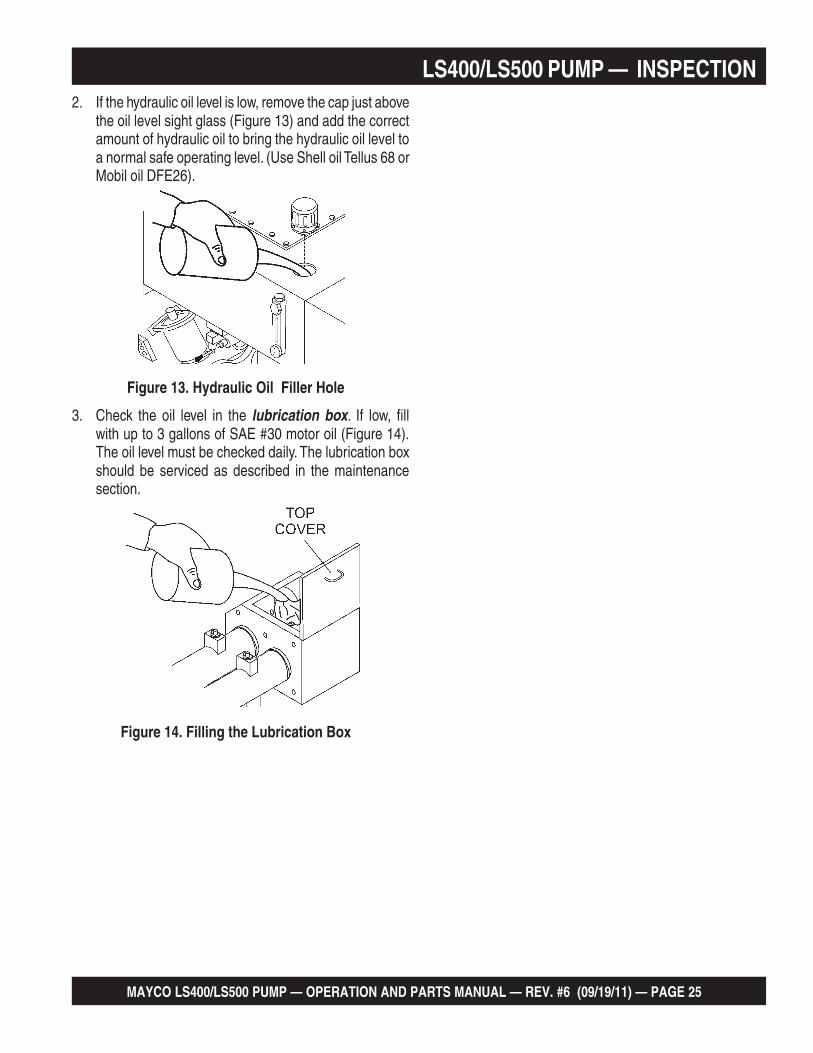
LS400/LS500 PUMP — INSPECTION2. If the hydraulic oil level is low, remove the cap just above
the oil level sight glass (Figure 13) and add the correctamount of hydraulic oil to bring the hydraulic oil level toa normal safe operating level. (Use Shell oil Tellus 68 orMobil oil DFE26).
Figure 13. Hydraulic Oil Filler Hole
3. Check the oil level in the lubrication box. If low, fillwith up to 3 gallons of SAE #30 motor oil (Figure 14).The oil level must be checked daily. The lubrication boxshould be serviced as described in the maintenancesection.
Figure 14. Filling the Lubrication Box

PAGE 26 — MAYCO LS400/LS500 PUMP — OPERATION AND PARTS MANUAL — REV. #6 (09/19/11)
LS400/LS500 PUMP — SET-UPLOCATION OF PUMP
1. Place the pump in the best location on the site to pumpconcrete efficiently.
2. Lay down the hose in the shortest distance possible.
REAR STABILIZER JACKS
To reduce excessive vibration and rocking of the pump, setthe rear stabilizers as follows:
1. Locate both the left and right rear stabilizer jacks(Figure 15).
2. Remove the cotter pin from the handle tee bolt eye,and then pull the handle tee to release the stabilizerjack (Figure 16).
3. Position both rear stabilizers jacks on firm (not loose)level ground (Figure 17).
4. Align the hole on the stabilizer jack with the hole on theframe body and insert handle tee bolt.
5. Insert the cotter pin into handle tee bolt eye to lock thestabilizer jack.
Figure 15. Locating Rear Stabilizer Jacks
Figure 17. Rear Stabilizer Stand Deployment
HYDRAULIC REAR STABILIZER JACKS (OPTIONAL)
If your pump comes equipped with hydraulic rear stablizers,they can be controlled as follows:
1. Push down the middle control lever (see Figure 18) toextend the right hydraulic rear stabilizer.
2. Push up the middle control lever (see Figure 18) to retractthe right hydraulic rear stabilizer.
3. Push down the rightmost control lever (see Figure 18)to extend the left hydraulic rear stabilizer.
4. Push up the rightmost control lever (see Figure 18) toretract the left hydraulic rear stabilizer.
REARSTABILIZERSTAND
BOLT EYE
HANDLET-BOLT
COTTERPIN
Figure 18. Control Levers for Hydraulic Rear Stabilizers
Figure 16. Rear Stabilizer Jack
NEVER place feet under jack while operating.
ALWAYS retract rear stabilizer jacks prior to towing.
ALWAYS retract rear stabilizer jacks prior to servicing torelieve load (working pressure).
WARNING - REAR STABILIZER SAFETY
RIGHT HYDRAULICSTABILIZER JACK
LEFT HYDRAULICSTABILIZER JACK
MIDDLE CONTROL LEVER(CONTROLS RIGHTHYDRAULIC STABILIZER)
RIGHTMOSTCONTROL LEVER(CONTROLS LEFTHYDRAULICSTABILIZER)
REARSTABILIZERJACKS

MAYCO LS400/LS500 PUMP — OPERATION AND PARTS MANUAL — REV. #6 (09/19/11) — PAGE 27
2. Turn the Cylinder Stroke Control Switch to theAUTOMATIC position (Figure 20).
3. Place the Pumping Control Switch to the CENTEROFF position (Figure 21) for normal pumping operation.
Figure 19. Emergency Stop Switch
Em
ergency Stop
LS400/LS500 PUMP — START-UP PROCEDURE
DO NOT attempt to operate this concrete pump untilthe Safety, General Information and Inspectionsections have been read and understood.
STARTING PROCEDURE
If the Emergency Stop switch is in theCLOSED position (stop), engine will not start.To star t the engine, make sure theEmergency Stop switch is in the OPENposition (fully extended).
WARNING - GENERAL SAFETY GUIDELINES
1. Locate the Emergency Stop Switch (Figure 19) on theHydraulic Pump Control Box. Turn the Emergency Stopswitch clockwise and release (open). This will allow theengine to start.
Figure 20. Cylinder Stroke Control Switch (Automatic)
5. To start the engine, insert the key (Figure 23) into theignition switch and turn the key to the ON position.
6. When the ignition key is in the ON position, the DigitalReadout Screen (primary) will cycle through 3 displaysas shown in Figure 24.
LOCAL REMOTE
CENTEROFF
4. Place the Direction Control Switch to the FORWARDposition (Figure 22).
AUTOMATIC JOG
Figure 21. Pumping Control Switch (OFF)
FORWARD REVERSE
Figure 22. Direction Control Switch (FORWARD)
Figure 23. Ignition Switch
7. Turn the key to the START position and listen for theengine to start. In warm weather let engine warm up for5 minutes. In cold weather let engine warm up for 10minutes.
LS 400 OFF0000 ENG RPMBATTERY 12.5 VLOW OIL PSI
1
LS 400 OFF0000 ENG RPMBATTERY 12.5 VLOW RPM FAULT
1
LS 400 OFF0000 ENG RPMBATTERY 12.5 VEND OF MESSAGE
1
Figure 24. Primary Screen (Ignition Key ON)

PAGE 28 — MAYCO LS400/LS500 PUMP — OPERATION AND PARTS MANUAL — REV. #6 (09/19/11)
HOSE LUBRICATION
Before pumping, it is necessary to lubricate the hose.
This procedure prevents separation and blockages in thehose. Inspect the lines at all times to prevent problems.
Before concrete is discharged into the hopper, it is suggestedthat 3 to 4 gallons of water be sprayed into the hopper,followed by approximately 5 gallons of a creamy cement andwater slurry (1/2 bag of cement to 5 gallons of water).
PRIMING THE PUMP WITH SLURRY MIXTURE
It is CRITICAL to the successful operation of a concretepump that the manifold and all delivery hoses, pipes andelbows are coated with a film of lubrication BEFORE youattempt to pump concrete.
Failure to properly prepare the pump and system will resultin a “dry pack” of concrete, blocking the shuttle valve tubeor delivery line.
1. Connect the entire delivery system to the pump. Pour 5gallons of water and a bag of raw cement into the hopper.
2. Place the Direction Control Switch to the REVERSEposition (Figure 25). This will mix the water and cementinto slurry.
3. Mix the slurry to the consistency of a smooth batter.
4. Position the first ready-mix truck at the hopper. Checkthe concrete. DO NOT discharge concrete into hopperat this time.
5. Place the Direction Control Switch in the FORWARDposition. This will start the flow of the slurry to the hoses.
6. Keep the slurry flowing until most of it is pumped out.However, make sure that some slurry is left on the hopperwhen concrete is first discharged from the ready-mixtruck.
LS400/LS500 PUMP — OPERATION
Getting the concrete to flow through thehose at the start of the pumping cyclecan be one of the most critical opera-tions of the pour.
PUMPING
FORWARD REVERSE
Figure 25. Direction Control Switch (REVERSE) A thumping sound (cylinder stroke) should be heard.The thumping sound represents the number of strokesper minute (volume) of the pump.
3. Scroll through the Digital Readout Screen with the scrollswitch to go to Screen 7 (Figure 28). This screen willshow the volume in strokes per minute.
2. Slide the Volume Control Switch (Figure 27) to theright to increase the volume to approximately 10 strokesper minute. Sliding the volume control to the left willdecrease pump volume.
Figure 27. Volume Control
INCREASEVOLUME
DECREASEVOLUME
+_
THROTTLE ONSTROKES: 100STROKES/MIN 10.0YDS/HR 0.0
7
Figure 28. Strokes Per Minute Display
1. Place the Pumping Control Switch to the LOCALposition (Figure 26) for normal pumping operation.
LOCAL REMOTE
CENTEROFF
Figure 26. Pumping Control Switch (LOCAL)
Safety glasses MUST be worn atall times when operating the pump.Failure to follow safety guidelinescan result in serious injury.
WARNING - SAFETY GLASSES
A well-planned location of the pump androuting of the hose before starting a pour maysave subsequent moves throughout the job.
MAYCO LS400/LS500 PUMP — OPERATION AND PARTS MANUAL — REV. #6 (09/19/11) — PAGE 29
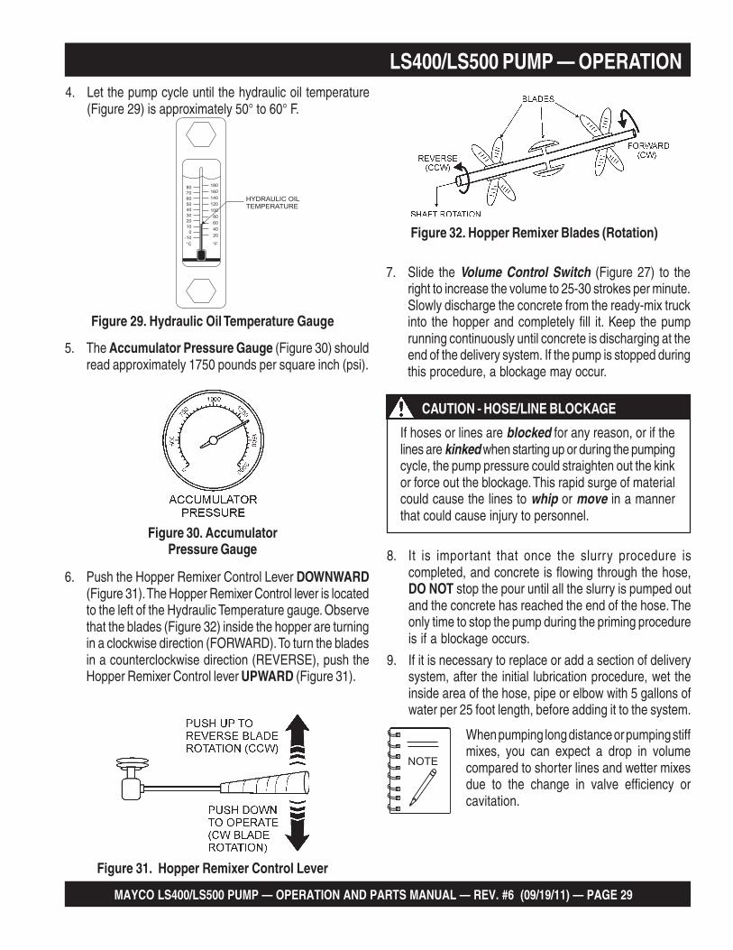
Figure 30. AccumulatorPressure Gauge
5. The Accumulator Pressure Gauge (Figure 30) shouldread approximately 1750 pounds per square inch (psi).
LS400/LS500 PUMP — OPERATION
If hoses or lines are blocked for any reason, or if thelines are kinked when starting up or during the pumpingcycle, the pump pressure could straighten out the kinkor force out the blockage. This rapid surge of materialcould cause the lines to whip or move in a mannerthat could cause injury to personnel.
CAUTION - HOSE/LINE BLOCKAGE
When pumping long distance or pumping stiffmixes, you can expect a drop in volumecompared to shorter lines and wetter mixesdue to the change in valve efficiency orcavitation.
8. It is important that once the slurry procedure iscompleted, and concrete is flowing through the hose,DO NOT stop the pour until all the slurry is pumped outand the concrete has reached the end of the hose. Theonly time to stop the pump during the priming procedureis if a blockage occurs.
9. If it is necessary to replace or add a section of deliverysystem, after the initial lubrication procedure, wet theinside area of the hose, pipe or elbow with 5 gallons ofwater per 25 foot length, before adding it to the system.
7. Slide the Volume Control Switch (Figure 27) to theright to increase the volume to 25-30 strokes per minute.Slowly discharge the concrete from the ready-mix truckinto the hopper and completely fill it. Keep the pumprunning continuously until concrete is discharging at theend of the delivery system. If the pump is stopped duringthis procedure, a blockage may occur.
Figure 29. Hydraulic Oil Temperature Gauge
4. Let the pump cycle until the hydraulic oil temperature(Figure 29) is approximately 50° to 60° F.
6. Push the Hopper Remixer Control Lever DOWNWARD(Figure 31). The Hopper Remixer Control lever is locatedto the left of the Hydraulic Temperature gauge. Observethat the blades (Figure 32) inside the hopper are turningin a clockwise direction (FORWARD). To turn the bladesin a counterclockwise direction (REVERSE), push theHopper Remixer Control lever UPWARD (Figure 31).
Figure 31. Hopper Remixer Control Lever
Figure 32. Hopper Remixer Blades (Rotation)
HYDRAULIC OILTEMPERATURE

PAGE 30 — MAYCO LS400/LS500 PUMP — OPERATION AND PARTS MANUAL — REV. #6 (09/19/11)
LS400/LS500 PUMP — OPERATION
Figure 37. Radio Remote Control
REMOTE CONTROL (OPTIONAL)
The LS400/LS500 Concrete Pump has a remote controlfeature that allows the pump to be remotely controlled. Ifdesired, the pump can be operated via a receiver/transmitter(radio) or a hardwire method, which utilizes a 25-ft. extensioncable. Contact MQ Sales Department to order remote control.
Radio Remote Control
Installation of the Radio Remote Control Assembly
1. Remove the two screws on the digital control panel ofthe pump. See Figure 33.
2. Tilt and slowly pull out the control panel and place ontop of box to gain access inside the box. See Figure 34.
3. Install the wireless remote module with the 2 screwsand nuts provided inside the control panel. Connect the3-wire connector from the wireless remote module tothe electronic control unit. See Figure 35.
Radio Remote Control Buttons Operation
The pumping operation can be performed by radio remotecontrol (Figure 37). Before using remote control, move thePumping Control Switch on the control box to the REMOTEposition. The buttons on the remote control have the followingfunctions.
ON/OFF - Turns the power on or off. When power is on thepower LED lights red. If the battery LED turns red, 9V batteryneeds to be replaced.
E-STOP - Turns off the pump completely in an emergency.
PUMP ON/OFF - Starts and stops the forward pumping.
PUMP REV - momentarily pumps in reverse direction.
VOLUME (+) - used to increase the pumping volume.
VOLUME (-) - used to decrease the pumping volume.
Figure 33. Removing Screws from Control Panel
EMERGENCY
S
TO
P
OFF
ON
IGNITION
REMOTE
CONTROL
FLOWDIRECTION
VOLUME
LOCAL
FORWARD
AUTOMATIC
JOG
RESET
SET
DECREASE
INCREASE
SCROLL
JOG“A”
CYLINDERSTROKE
JOG“B”
REVERSE
CENTEROFF
REMOTE START
REMOVE 2 SCREWS
CONTROL BOX
Figure 34. Pulling Out Control Panel
4. Reinstall the control panel and tighten the 2 screws.
5. On the top of the unit, to the right of the control box(Figure 36), hammer out the knock-out hole and installthe remote antenna.
6. Connect the antenna cable to the connector on the rearof the control box (Figure 36).
Figure 35. Installing Remote Control Module
Figure 36. Antenna Installation
ANTENNA
KNOCK-OUTHOLE
ANTENNACONNECTORCABLE
CONTROL BOXCONNECTOR
REAR OFCONTROL BOX
SCREWS AND NUTS
WIRELESSREMOTEMODULE
CONNECTOR
ELECTRONICCONTROLUNIT
E-STOPONOFF
PUMPREV
VOLUME VOLUME
PUMPON/OFF
POWER LED
NOTE: OLDER MODELSMAY INDICATEINSTEAD OF
FLOW
VOLUME
BATTERY LED

MAYCO LS400/LS500 PUMP — OPERATION AND PARTS MANUAL — REV. #6 (09/19/11) — PAGE 31
It will be necessary at times to move your pump fromone job site location to another. Before moving thepump, make sure to pump the remaining concrete outof the hopper. Moving the pump with a full hopper ofconcrete can cause severe damage or breakage ofthe axle and axle springs, excess strain and pressureon the hub and bearing assembly.
WARNING - TRANSPORTING PUMP
Leaking manifold seals or hose couplinggaskets which leak water can cause separa-tion and subsequent jamming at that point.
LS400/LS500 PUMP — OPERATION
Cable Remote Control
Installation of the Cable Remote Control Assembly
Connect the cable to the front panel of the control box (SeeFigure 38).
CABLE REMOTE CONTROL UNITCABLE REMOTE CONTROL UNIT
25 FT. CABLE25 FT. CABLE
PUMP REV
PUMP ON/OFF TO CONTROL BOXCONNECTORTO CONTROL BOXCONNECTOR
Figure 38. Cable Remote Control
Radio Remote Control Programming
Before starting operation of the Radio Remote Control, goto Screen 9 of the Digital Readout Screen:
1. Press the ON/OFF button on the radio (wireless) remotecontrol to turn on the power. Hold down the RESETswitch. The display will now show:
2. After 5 seconds, the display will show:
3. The remote control is now ready for use.
RADIO ADDRESSNO RADIOPRESS RESET TOLEARN A NEW ONE
9
RADIO ADDRESSNOW SCANNINGFOR NEWTRANSMITTER
9
Cable Remote Control Operation
Before using cable remote control, set the pumping volumewith the VOLUME switch on the control box then move thePumping Control Switch on the control box to the REMOTEposition.
The cable remote control (Figure 38) has the followingcontrols.
PUMP ON/OFF - Starts and stops the forward pumping.
PUMP REV - starts pumping in reverse direction.
RADIO ADDRESSCOMMUNICATINGPRESS RESET TOLEARN A NEW ONE
9

PAGE 32 — MAYCO LS400/LS500 PUMP — OPERATION AND PARTS MANUAL — REV. #6 (09/19/11)
It is strongly recommended that steel pipebe used on all vertical pumping for safety andconvenience.
When pumping is resumed, you can expect blockage at thepoint of hose collapse. To prevent this from happening, thehose can be “kinked off” at the discharge end when the pumpis stopped to prevent the gravity flow of the material in thehose.
The use of stiffer mixes when pumping downhill will decreasegravity flow of the material in the hose and will assure asmoother operation between the cam roller bearing and camplate. As with any job, make sure that the hose and thecouplings are in good workable shape.
VERTICAL PUMPING
When pumping vertically up the side of a building, above 40feet, we would recommend the installation of steel pipesecurely fastened at intervals as necessary to support thepipe. Ninety degree, long radius pipe sweeps should beinstalled at the top and bottom of the steel line.
Use a 25 ft. hose, or short section, off the pump; and for thebalance of the horizontal distance to the vertical line, usesteel pipe. This type of installation has been satisfactory onmany jobs being pumped in excess of 100 feet high. Linepressures are always less using steel pipe as compared tohose.
When pumping vertically, using all hose, it is recommendednot to go higher than 50 feet with hose. The hose should betied off at intervals of 10 feet, if possible. Special attentionshould be given when tieing the hose off at the top as the hosewill have a tendency to stretch when filled with concrete. Thiswill increase the possibility of a blockage at the point wherethe hose is tied off. To avoid this, a long radius of 90º elbowis recommended. The suggested place to tie off is on thehose, under the clamp.
LS400/LS500 PUMP — PUMPING INFORMATION
All admixtures will be shown on the redi-mixconcrete ticket. Before starting the pumpingjob, ask the driver of the redi-mix truck to seethe concrete ticket and note the admixturesthat exist and take the proper action.
REMIXTURES
Remixtures that are designed into the concrete mix by theredi-mix company or an architectural engineering company.This section lists common admixtures and a brief explana-tion of their functions:
A. Pozzolith 300 – or the equivalent acts as a waterretarder and a lubricant. On a lean mix, long pushes,stiff mixes, and vertical pushes, Pozzolith 300Rhelps pumpability.
B. MBVR – air entraining, acts as a lubricant.
C. Calcium Chloride – commonly referred to as C.C.,is used as an accelerator. When pumping a load withcalcium chloride, it is recommended that you washout if the waiting time between delivery trucksbecomes too long.
D. Super Plasticizers – acts as an accelerator. Theconcrete will look very wet after the super plasticizeris added, but will begin to set up very fast. Wash outimmediately if you do not have a truck waiting. Superplasticizers are used mainly on commercial jobs.
E. Red Label – acts as a water retarder and anaccelerator. Red label will be used mainly on com-mercial jobs.
F. Fly Ash – is used to help increase the strength ofthe concrete and decrease the cement content peryard. This is one of the most common admixturesused.
DOWNHILL PUMPING
Downhill pumping can be a difficult procedure on some jobs.The slurry procedure would be the same as explainedPriming The Pump With Slurry Mixture section of this manual.It is suggested that a sponge approximately 2”x 4”x 6” in sizebe placed in the hose before the start of pumping.
Wet the sponge before placing it in the hose to keep the slurryfrom running too far ahead of the concrete, which will reducethe possibility of separation. When the pump is stopped, thematerial can flow slowly down, due to gravity, and cause thehose to collapse.
HOSE PULSATION
A slight pulsation of the hose will always be noticeable nearthe pump. Excessive pulsation of the hose near the pump isnormally due to higher than average line pressures caused bystiff, harsh mixes, or extremely long pumping distances.

MAYCO LS400/LS500 PUMP — OPERATION AND PARTS MANUAL — REV. #6 (09/19/11) — PAGE 33
The use of 2 -1/2” I.D. hose in these extreme cases reducesline pressures or the addition of slight amounts of water to themix, if permissible, will permit easier pumping. The use ofcertain pumping admixtures may help.
If excessive pulsation exists in the hose, it is advisable touse burlap or some means of wear protection under the hoseat points where the hose may wear through the outer cover;e.g. over forms, steel or sharp curbs.
SNAP-JOINT COUPLINGS
When using Snap-Joint couplings with gaskets to join hose,see that they are washed clean after each job. Keeping thehose ends clean (heavy duty) is very important for the bestjob setup. A thin coat of grease on the rubber gasket ordipping both coupling and gasket in water before coupling thehose will make for easier installation.
NEW PUMPS
All new pumps are ‘water pressure tested” at the factory Thisprocedure permits a thorough inspection of entire drivesystem and valving under simulated full load conditions. Thepump owner can do the same by making an adapter to coupleto the end of the discharge cone: e.g., the use of a standard2" pipe cap with a 3/8" drilled hole in the center, screwed onto the end of hinged cone or reducer at the pump.
Fill the hopper with water after making sure that all sand androck have been removed from manifold. Operate pump at fullthrottle and the 3/8" diameter hole restriction will createsufficient back pressure to make thorough inspection of allmoving parts.
LS400/LS500 PUMP — PUMPING INFORMATION
THE EFFECTS OF HEAT AND EXCESSIVETIME ON CONCRETE:
Hot concrete, commonly referred to as a hot load, is concretethat has been in the redi-mix truck in excess of 2 to 3 hours.On a hot day, this amount of time is even less.
A brief explanation of why heat and time affect concrete:
Concrete starts setting by drying up through a chemicalreaction. The catalyst to this reaction is heat. Whenpumping a hot load, it is important to remember thatwhen you have to stop pumping for any reason, addwater to the concrete in the hopper and hand mix andmove concrete in the hose every 5 minutes. If the shutdown time becomes too long, wash out immediately.
If it is necessary to wait 1/2 hour or more for another load ofconcrete, to prevent setting of the mix in the system, it isadvisable to consider the following factors (A through D)affecting the concrete:
A. How old is the concrete?
B. Is there an accelerator, calcium chloride, red label,etc., in the concrete?
C. The temperature of the day, 80, 90, degrees?
D. How much system you have out and how stiff wasthe mix you were pumping?
PREVENTING MIX SET-UP AFTER PUMP SHUTDOWN
When the pump is stopped for any reason during a pour; e.g.,moving hose, waiting for redi-mix truck, the following sugges-tions are offered:
1. Leave the hopper full of concrete at the time of shutdown.It is important not to let the redi-mix driver wash toomuch water into the hopper, as this could cause separa-tion of the concrete in the hopper.
2. If the shutdown period exceeds 2 to 3 minutes, turn offthe engine so the vibration does not separate the mix inthe hopper which can cause a blockage in the manifoldwhen the pump is started.
3. If it is necessary to wait 10 minutes or more for anotherload of concrete, it is wise to start the pump and pump6 or 8 strokes every 5 minutes to prevent setting of themix in the system. If waiting time is excessive, it wouldbe wise to wash out the pump and hoses and start overwhen the new truck arrives.
4. When pumping stiff mixes and there is waiting timebetween redi-mix trucks, it is advisable to add somewater to the last hopper of material and “hand mix” toensure an easier start with the following load.
5. When the pumping job requires a stiffer mix, the followingmethod is suggested for starting: Take a water hose witha nozzle on it and apply water with a fine spray to theconcrete as it comes down the redi-mix chute into thepump hopper after the slurry procedure is completed andyou are ready to start pumping.

PAGE 34 — MAYCO LS400/LS500 PUMP — OPERATION AND PARTS MANUAL — REV. #6 (09/19/11)
CLEARING THE SYSTEM AFTER MIX SET UP
If, for any reason, the mix should set up in the system, thefollowing procedure is suggested:
1. Disconnect the hose from the pump and wash the pumpout immediately.
2 Reconnect the hose and fill the hopper with water.
3. Reconnect the hose and fill the hopper with water. DONOT try to push all the concrete out of all of the hose linesat one time.
For example: If you had 200 ft. of system out, you woulddisconnect each hose. Clean it out by pushing waterthrough the first hose off the pump, then continueprogressing through all the hoses, until all the system isclean.
4. If waiting time is excessive, it would be wise to wash outthe pump and hoses and start over when the new truckarrives. This can be avoided by being observant to thepump and system, also taking into consideration theabove actors (A through D) affecting the mix.
When disconnecting hoses, use EXTREMECAUTION! The hose is under pressure!
WARNING - HOSE/LINE PRESSURE
Using this procedure will make it easier to pump throughthe clean hose. Note: Once the concrete has reached theend of the hose, do not apply any more water in thismanner as this procedure is used for starting only.
6. Hose sizing is very important: We strongly recommendon harsh mixes, vertical pushes, stiff concrete, shotcrete,long pushes, that a 2 -1/2” line be used as far as possible.The advantages of using the 2 -1/2” line are improvedpumpability, less pumping pressure and less wear on thepump.
7. Following the pump operation, proper wash out of allmaterials or “build-up” within the pump manifold andhoses will prevent problems when starting the next job.
8. A thorough inspection of the drive components andgreasing of all bearings after each job will ensure ad-equate lubrication and service to the pump which isnormally operating in wet, gritty conditions.
Over-greasing any bearing on your Maycopump will not damage the bearing.
LS400/LS500 PUMP — PUMPING INFORMATION
If a blockage occurs in a hose, walk the hose until you findthe point of trouble. The hose will be soft immediately past theblockage. To clear the blockage:
1. Disconnect the hose at the first coupling past theblockage.
If you repeatedly pull the throttle all the way out andtry to force your pump to push through blockagesdue to separation of material in the hose or manifold,you will soon have breakdowns and costly repairs whichare not covered under warranty.
If a blockage occurs, find where it is and clear it beforefurther pumping. DO NOT increase the engine speedto clear the blockage. Increasing the engine speedwill only compound the problem.
WARNING - BLOCKAGES
CLEARING CONCRETE BLOCKAGE
Damaged hoses with internal restrictions cancause blockages.
Use extreme care! The hose line is under pressureand can cause serious injury.
WARNING - HOSE LINE PRESSURE
2. Elevate the hose at that point with the blockage areahanging down.
3. Using a hammer, you can pound the downstream edgeof the packed area until it is free to flow. Shake all of thesand and gravel out to the end of the hose.
4. Before reconnecting the hose, start the pump and run asmall amount of concrete out to the end of the hose. Thiswill assure that all of the separation is out of the hose.

MAYCO LS400/LS500 PUMP — OPERATION AND PARTS MANUAL — REV. #6 (09/19/11) — PAGE 35
DO NOT open any of the delivery system joint clamps.
“REVERSE” PUMPING PROCEDURE
A. Switch the pump into REVERSE. With pump speedat a medium-slow (approx. 12 strokes per min.) tryto pull the “pack” back into the hopper with 5 or 6reverse strokes.
B. Remix the concrete in the hopper.
C. Switch the pump into FORWARD. If it is still plugged,repeat “Reversing” procedure three times.
If concrete still does not move, proceed to the Shuttle TubeInspection Procedure.
The shuttle tube is plugged if volume at the discharge end ofthe hose stops and the hydraulic oil pressure gauge reads4400 PSI or more.
To clear a plug in the shuttle tube, great care must be takenas a dangerous condition will exist from pressure build-upinside the shuttle tube. (With the shuttle valve, the concretecan be pumped in reverse.) Use the following procedures toclear the shuttle tubes.
WARNING - SHUTTLE TUBES
CLEARING SHUTTLE TUBE BLOCKAGE
Make sure the accumulator pressure gauge readsZERO psi. prior to performing any maintenance orinspection. You must follow lock out-tag outprocedures.
WARNING - ACCUMULATOR PRESSURE
SHUTTLE TUBE INSPECTION PROCEDURE
A. Stop the pump. Switch off the engine.
B The senior or most experienced operator must warnall others to stand at least 20 feet away from themachine and turn their heads to face away from thepump.
C. The operator will position himself beside the reducingelbow at the pump outlet. Wearing safety glasses,slip the end of a pry bar (24" length of reinforcingsteel rod) under the latch of the hose clamp and flipit up.
D. Carefully knock the end of the hose away from thereducer.
E. Chip the concrete out of the reducer with the prybar.
F. Remove the reducer. From the discharge end, chipthe concrete out of the shuttle tube with the pry-bar.If concrete cannot be loosened from the outlet ofthe shuttle tube, remove the clean-out plug on thebottom of the hopper to discharge the concrete.
G. Chip the blockage out with the pry-bar.
H. Flush the shuttle tube with water.
I. Before resuming operation of the pump, perform the“Reverse” Pumping Procedure to relieve pressureon the shuttle tubes.
LS400/LS500 PUMP — PUMPING INFORMATION

PAGE 36 — MAYCO LS400/LS500 PUMP — OPERATION AND PARTS MANUAL — REV. #6 (09/19/11)
LS400/LS500 PUMP — MAINTENANCE (PUMP)TABLE 5. MAINTENANCE CHECK SCHEDULE
Daily Hour-ly
Wee-kly
Month-ly
6-Mont-hs
OperationalHours
Engine Oil X X
Engine Air Filter X
Fuel Filter X
Hydraulic Oil Level X 500 hrs.
Lubrication Box X
Replace Hydraulic Oil 1000 hrs.
Clean Hydraulic Filters X 500 hrs.
Axle Crank X 2 hrs
Grease Shuttle Tube and HopperOutlet Zerk Points 2 hrs
Check System Pressure X 40 hrs.
Check Hardware for Tightness X 40 hrs.
Check Cutting Ware Ring and Plate X
Check Trailer Brakes Function X
Check Brake Lights X
Check Tire Conditions X
Inspect Saftey Devices / Decals X
Check Wheel Bearings X
Check Battery X
Inspect Brake Lining X
Visually Check for Oil Leaks X
CLEANING THE PUMP AND DELIVERY SYSTEM
Cleaning the pump is a very important operation as itdetermines how the machine will pump the next time it isused.
At the end of every pour, or because of long delays during apour, the pump and delivery system must be thoroughlycleaned by removing all concrete material.
1. Following the Clearing Concrete Blockage operatingprocedure, ensure that there is no blockage in the hoseand line or in the shuttle tube. If a blockage exists, clearit.
2. Pump concrete until the opening of the concrete cylinderintake in the hopper is visible.
3. Stop the pump.
4. Carefully disconnect the first hose joint at the shuttletube discharge elbow.
During routine maintenance or removing materialblockage, you will be required to put your hand in theconcrete cylinders or near the shuttle tube. You are atEXTREME RISK of injury or AMPUTATION if theengine is running or if pressure is in the hydraulicsystem.
Prior to performing any maintenance on the pump,follow described lock out-tag out procedures. Stop theengine by turning off the ignition switch and removethe starter key. Place a “DO NOT OPERATE” tagover the switch and disconnect the battery. Thepressure reading on theaccumulator pressuregauge MUST readZERO. ALWAYS makesure the accumulatorcircuit pressure readszero prior to performing any maintenance on the pump.
DANGER - AMPUTATION RISK

MAYCO LS400/LS500 PUMP — OPERATION AND PARTS MANUAL — REV. #6 (09/19/11) — PAGE 37
LS400/LS500 PUMP — MAINTENANCE (PUMP)HYDRAULIC OIL SYSTEM MAINTENANCE
The Mayco pump is equipped with an in-tank return hydraulicfilter with a 10 micron cleanable filter. The element has beendesigned to remove all particles large enough to cause wearand job break down. Under normal conditions, we recommendreplacement every 6 month.
DO NOT mix oil brands! This may impair quality.
Use only a 2½" diameter clean-out hookwhen back-pumping into redi-mix truck. Usea safety chain to secure the clean-out hookto some solid part of the mixer truck toprevent hook from jumping off of the drum.Run the pump at 6 strokes per minutemaximum speed.
2. Lubrication: Grease daily/Hour(Recommended after each Pour)
■ Main hydraulic cylinders - 2 Place
■ Axle crank - 1 Place
■ Shuttle cylinders - 2 Place
■ “S” tube outlet flange - 3 Place
Grease Type: Lithium Based EP
Texaco Multitak 20
Lubriplate ED-2
The most important factor to keep in mind is the effect ofcold weather on the hydraulic oil. The viscosity (thickness)of the hydraulic oil will be much heavier.
ALWAYS run machine until oil temperature reaches aminimum of 50°F. before pumping. Damage to the main pistonpump will occur if the machine is cycled too fast before theoil temperature reaches the minimum of 50°F. Cycle themachine at 6-8 strokes per minute at approximately 1/3throttle.
In areas where the weather normally remains under 50°F.,use Shell Oil Tellus 46 (or the equivalent). The above stepsmust be followed or severe damage to the main axial pistonpump can occur.
1. When changing the hydraulic oil or topping off thereservoir, use only the following type.(Reservoir capacity - 50 gal.)
Hydraulic oil: Shell Oil Tellius 68 or
Mobil DFE 26
Texaco Rand HDC
NEVER use muriatic acid to clean the pump. Acid willdissolve the chrome finish on material cylinder boreand main hydraulic cylinder rods.
Deutz Model F4L2011F/BFL2011F Diesel Engine
This pump is equipped with either a Deutz F4L2011F or DeutzBF4L2011F turbo diesel engine. For information concerning theprocedure in checking, removing, cleaning, etc. of the variousengine parts or any other information on the engine not containedherein, refer to the engine manufacturer’s instruction manual.
WARNING - HYDRAULIC OIL
WARNING - ACID CLEANING
5. Add water to the hopper. Pump and flush clean the entirehopper, shuttle tube and discharge elbow with water.
6. Scoop out 12 inches of concrete from the inboard endof the delivery hose. “Cork screw” a 6" x 6" x 8" spongeinto the end of the first hose section. Reconnect thehose to the discharge elbow.
7. Fill hopper with water. Pump until sponge and clean watercome out the discharge end of the hose and line system.
8. When the pump has been used to pump small aggregateconcrete (pea rock, ½" minus) or mixes with high finescontent (60% or more sand) there will be a tendency forhardened concrete to build up on the inside surface ofthe shuttle tube. Therefore, at the end of every suchpour, after the pump and system have been cleanedand the engine shut off, remove all remaining concrete.
9. When the pump has been used to pump large aggregateconcrete (" to 1 (" follow the instructions in step 8 onceper week.

PAGE 38 — MAYCO LS400/LS500 PUMP — OPERATION AND PARTS MANUAL — REV. #6 (09/19/11)
BRAKE SYSTEM
The brake system should be periodically checked. Look forfluid leaks worn or cracked hoses. Check the reservoir forproper fluid levels. The Atwood surge brake should bechecked for damage. Make sure that all links and pivots arekept lubricated.1. Keep all links and pivots lubricated to prevent rusting
and ensure ease of operation. Using SAE 30 oil, lubricateinside the release handle and inside the actuator body.This can be reached from the underside of the actuator.
Lubricate the hitch ball with conventionalautomotive grease or a lubricant made forhitch balls.
2. Check for any leaks in the brake system. Periodic checksshould be made on all hoses to guard against cuts andworn hoses which may cause failure (leaks, rupturingunder pressure, and collapsing). Replace defective hoses.
DO NOT fill the master cylinder reservoir with usedbrake fluid. DO NOT fill the reservoir beyond ½" fromtop. DO NOT overfill; brake fluid will damage paint.
3. Check the brake fluid level in the master cylinder reservoir.Keep it filled to within ½" from the top of the reservoir.
4. At the beginning of each year, inspect the brakes forexcessive wear, replace the linings if necessary.
Wheel bearings and seals should beinspected and packed at this time.
Figure 39. Battery Electrolyte Levels
LS400/LS500 PUMP — MAINTENANCE (PUMP)
Wear safety glasses or face mask,protective clothes, and rubber gloves whenworking with battery.
CAUTION - BATTERY MAINTENANCE SAFETY
Mishandling of the battery shortens the service life of thebattery and adds to maintenance cost. When handling thebattery do the following:
Be careful not to let the battery electrolyte come incontact with your body or clothing.
Always wear eye protection and rubber gloves, sincethe battery contains sulfuric acid which burns skin andeats through clothing.
Always check the battery terminals periodically toensure that they are in good condition.
Use wire brush or sand paper to clean the batteryterminals.
Always check battery for cracks or any other damage.If white pattern appears inside the battery or paste hasaccumulated at the bottom, replace the battery.
If the pump will not be in operation for a long period oftime, store in cool dry place and check the battery chargelevel every month to maintain the performance of thebattery.
Check the battery regularly and make sure that eachelectrolyte level is to the bottom of the vent well(Figure 39). If necessary add only distilled water in awell-ventilated area.
CAUTION - MASTER BRAKE CYLINDER
BATTERY MAINTENANCE

MAYCO LS400/LS500 PUMP — OPERATION AND PARTS MANUAL — REV. #6 (09/19/11) — PAGE 39
CLEANING THE LUBRICATION BOX
1. Remove the top cover and the drain plug (Figure 40)located at the bottom of the box and fully drain the insideof the box.
2. Once the box is drained, start the engine and stroke thecylinder (keep hands out of box) ten to fifteen times.
3. While stroking, spray water inside of the box tothoroughly clean out all contamination (Figure 40).
4. When the box is clean replace drain plug, add newlubrication and install the top cover.
1. The lubrication level should be checked everyday priorto pumping and maintained at a height of 5 inches orabout ½ the concrete cylinder height. We recommendusing a 30-weight motor oil.
CYLINDER LUBRICATION BOX
Figure 40. Cleaning the Lubrication Box
LS400/LS500 PUMP — MAINTENANCE (PUMP)ACCUMULATOR CIRCUIT
Figure 41. Accumulator
CHECKING ACCUMULATOR BLADDER PRESSURE
The normal accumulator charge pressure should beapproximately 1100 PSI. To check the accumulator pressure:
1. Start the engine and stroke the pump. The accumulatorpressure gauge (Figure 30) should read 1750 PSI.
2. To determine the actual accumulator PSI, stop theengine and observe the pressure gauge. As the PSIreading slowly decreases, it will reach a point wherethere will be a sudden drop in the PSI. The PSI readingshould be taken just prior to this sudden drop. If you donot read 1100 PSI, the accumulator may require chargingor bladder replacement.
When the pump cycles, a part of the stored oil is releasedto the shuttle cylinder. This pressure release assures theshuttle tube has enough force to shear the cylinder ofconcrete passing from the concrete cylinder to the concretedelivery line during the cycle phase.
Before checking lubrication level, follow lock out-tagout procedures. Stop the engine and remove theengine starter key.
2. As the rubber piston cups naturally wear, fine cementparticles will accumulate in the box. Once the concretepaste reaches a height of about ½ inch from the bottomof the box, drain and clean the lubrication box.
Improper accumulator charging can result in anexplosion causing serious injury or death! NEVER useoxygen or compressed air to charge the accumulator!Only qualified personal should perform this procedure.Use only dry nitrogen tocharge the accumulator.Contact your Maycoservice department or yourlocal Hydac representativefor proper chargingprocedure.
The accumulator circuit has two functions in the hydraulic system.
■ The accumulator circuit furnishes the hydraulic pressureto cycle the shuttle tube.
■ The accumulator circuit also furnishes the pilot pressurenecessary to activate the hydraulic system.
The accumulator circuit is equipped with abladder type accumulator (Figure 41)charged with 1100 PSI of dry nitrogen. Theaccumulator stores one gallon of hydraulicoil, which is, under 1750 PSI of pressure.
CAUTION - SAFETY GUIDELINES
DANGER - ACCUMULATOR CHARGING
When using the pump during freezing conditions,completely drain the water box and cover the hopperafter pumping. Frozen liquid will restrict the piston traveland cause severe damage to the pump.
WARNING - FREEZING CONDITIONS

PAGE 40 — MAYCO LS400/LS500 PUMP — OPERATION AND PARTS MANUAL — REV. #6 (09/19/11)
WEAR PLATE AND CUTTING RING
Due to the abrasive nature of concrete, it is normal for the cutting ring to wear on its sides as it shears through the concrete inside the hopper. The metal-to-metal friction and the abrasiveness of the concrete will cause extreme wear and reduce sealing capability between the cutting ring and wear plate. If the two components do not properly seat against each other, slurry will pump into the hopper rather than out the discharge line. See Figure A. This condition can easily be observed:
1. The sudden change of the level of concrete inside the hopper during each pumping stroke
2. Concrete slurry squirting into the air from the hopper (Volcano effect)
3. When the output volume at the end of the delivery line decreases in pressure
4. Unusual frequent material packs in the Shuttle tube
It is important that the wear components be inspected weekly for proper sealing. Failure to inspect will eventually cause severe damage to the nun-plate and material cylinders. Visually inspect wear plate and cutting ring to ensure surfaces are sealed against each other. If a deep groove or a wide space has developed on the sealing surfaces, it is time for replacement.
Due to the motion of the Shuttle tube, the cutting ring experiences a quicker rate of wear as opposed to the wear plate. The wear ring typically requires replacement two timesper wear plate (2 to 1). When replacing the wear ring, also replace the rubber energizer ring.
Figure A. Wear Plate and Cutting Ring
LS400/LS500 PUMP — MAINTENANCE (PUMP)

MAYCO LS400/LS500 PUMP — OPERATION AND PARTS MANUAL — REV. #6 (09/19/11) — PAGE 41
LS400/LS500 PUMP — MAINTENANCE (PUMP)
CYLINDER CUP REPLACEMENT PROCEDURE
1. Remove the two hydraulic hoses connected to the remixmotor. Plug the ports with fittings (not provided) toprevent hydraulic hose leakage.
2. Remove the hopper discharge nipple and loosen sleeveseal. Inspect and replace if wear is excessive.
3. Remove the two tie rod nuts and the four eyebolt nutssecuring the hopper to the pump frame.
CHANGING THE CONCRETE CYLINDER PISTON CUPS
The Rubber piston cups will occasionally require replacementdepending on the following factors.
■ The fluid level and cleanliness of the lubrication box.
■ The size and type of aggregate.
■ The type of concrete being pumped.
It is time to replace the cups when increasingly large particlesof sand and cement pass into the lubrication box. Do notallow the cups to become so worn that they begin to passlubrication into the material cylinders. If the liquid level ofthe lubrication box becomes to low, the rubber cups willseverely deform due to excessive heat. Wheneverreplacement is due, both cylinder cups should be replaced.
Before installing 3/8” bolt, coat the back ofbolt heads with silicon sealant. Torque all threebolts equal at 55 ft. lbs. each.
Felt ring must be saturated with 30 wt. oilprior to installation.
10. Install the felt holder over the oiler plate. Install felt ringinto felt holder. Install the bronze ring.
11. Using silicon sealant place a small bead of sealantmaterial on the front of the rubber piston cup and therear of the face plate. Install over alignment studs andinto concrete cylinders.
12. Insert one 3/8” 16x3” bolt into the open bolt hole, removethe alignment studs one at a time and install theremaining 3/8” 16x3” bolts.
4. Using an approved lifting device, remove the hopperusing extreme care not to damage the hopper seal.
5. Start the engine and turn on the pressure test switch.Cycle pump in reverse until hydraulic system obtainsmaximum pressure, then turn pump and engineoff.
Remove ignition key and disconnect battery. Thinksafety! Check the hydraulic gauges on panel and makesure accumulator pressure reads zero. One pistonshould be in the fully discharged position at the end ofthe concrete cylinder.
6. Remove the three 3/8 – 16 x 3” bolts from the piston.Remove the front faceplate.
7. Install two the 3/8’ 16x3” bolts back into the piston –do not tighten. Use the two bolts as leverage to removethe rubber piston cup and rear components.
8. Obtain two 3/8 16x7” full thread studs (these studs willbe used to assist in assembly alignment) insert thetwo studs into the piston adapter. Coat the concretecylinder with grease.
9. Install the “O” Ring around the oiler plate. Install theplate into the concrete cylinder utilizing the studs foralignment.
During routine maintenance or removing materialblockage, you will be required to put your hand in theconcrete cylinders or near the shuttle tube. You are atEXTREME RISK of injury or AMPUTATION if theengine is running or if pressure is in the hydraulicsystem.
Prior to performing any maintenance on the pump,follow described lock out-tag out procedures. Stop theengine by turning off the ignition switch and removethe starter key. Place a “DO NOT OPERATE” tagover the switch and disconnect the battery. Thepressure reading on theaccumulator pressuregauge MUST readZERO. ALWAYS makesure the accumulatorcircuit pressure readszero prior to performing any maintenance on the pump.
DANGER - AMPUTATION RISK

PAGE 42 — MAYCO LS400/LS500 PUMP — OPERATION AND PARTS MANUAL — REV. #6 (09/19/11)
CHANGING THE WEAR PLATE AND RING
Due to the swinging motion of the Nun-plate and the abrasivenature of concrete, it is normal for the cutting ring to wear onthe side that shears through the concrete inside the hopper.If the wear ring and wear plate do not fully seat against eachother the concrete slurry will pump into the hopper. Thiscondition can be easily observed by the sudden change ofthe level of concrete inside the hopper during each stroke.
Wear Plate and Ring Replacement Procedure
1. Remove the two hydraulic hoses connected to the remixmotor. Plug the ports with fittings (not provided) toprevent hydraulic hose leakage.
2. Remove the hopper discharge nipple and loosen sleeveseal. Inspect and replace if wear is excessive.
3. Remove the two tie rod nuts and the four eyebolt nutssecuring the hopper to the pump frame.
4. Using an approved lifting device, remove the hopperusing extreme care not to damage the hopper seal.
5. Remove the four 1/2” 1-¼” bolts that hold the shuttletube to the nun-plate and remove shuttle tube.
Using two small pry bars remove the rubber energizerring, steel insert ring and wear ring.
LS400/LS500 PUMP — MAINTENANCE (PUMP)
The energizer ring and wear ring willnormally have concrete contaminationholding them in position. It will be requiredto chip some of the concrete loose tobetter expose the energizer ring.
HEAT EXCHANGER COOLING FAN
This section is intended to make sure the fan is workingproperly. Under normal conditions the fan should be runningany time the engine is turned on.
If the hydraulic oil temperature exceeds 170 degreesFahrenheit, shut down the pump. DO NOT continueto operate the pump. Failure to shut down the pump willresult in severe damage to the pump.
CAUTION - HYDRAULIC OIL TEMPERATURE
6. Clean out all concrete build up in and around the nun-plate area with a wire brush.
7. Inspect the wear components for indications of wear.The wear plate has two wear surfaces.
Wear Plate Installation
1. Install the two cylinder “O” rings.
2. Using silicon sealant, coat the circumference of theconcrete cylinders, the back of the wear plate and aroundthe five bolt holes. Next, install the wear plate and thefive bolts. The bolts must all be equally snugged andtightened to 100 foot pounds each.
Wear Ring installation
1. Install the wear ring into the nun plate.
2. Install the steel insert ring inside of the rubber energizerring.
3. Install the energizer ring assembly into the nun-plate.
After installing the above mentioned components themachine can be reassembled by reversing steps 1 through5 of the Wear Plate and Ring Replacement Procedure.

MAYCO LS400/LS500 PUMP — OPERATION AND PARTS MANUAL — REV. #6 (09/19/11) — PAGE 43
LS400/LS500 PUMP — MAINTENANCE (PUMP)WHEEL BEARINGS
After every 6 months of operation inspect the wheel bearings.Once a year, or when required, disassemble the wheel hubsremove the old grease and repack the bearings forcing greasebetween rollers, cone and cage with a good grade of highspeed wheel bearing greases (never use grease heavier than265 A.S.T.M. penetration “No. 2.”).
1. Fill the wheel hub with grease to the inside diameter ofthe outer races and also fill the hub grease cap.
2. Reassemble the hub and mount the wheel. Then tightenthe adjusting nut, at the same time turn the wheel inboth directions, until there is a slight bind to be sure allthe bearing surfaces are in contact.
3. Back off the adjusting nut 1/6 to 1/4 turn or to the nearest
locking hole or sufficiently to allow the wheel to rotatefreely within limits of .001” to .010” end play. Lock thenut at this position.
4. Install the cotter pin and dust cap, and tighten allhardware.
EXTENDED STORAGE INSTRUCTIONS
The following preventative maintenance is recommendedfor extended periods of storage.
1. Check brake system for proper fluid level in mastercylinder and bleed all lines.
2. Lubricate all links and pivots to prevent any rusting.
3. Remove wheel and drum assemblies and spray a goodanti-corrosion compound (CRC formula 5-56) under rubberboot on forward end of brake wheel cylinder. Avoidspraying drum and brake lining.
4. Grease all bearings and reinstall wheel and drumassemblies.
5. Make sure breakaway cable is fully released.
6. After extended storage, refer to the Maintenance Stepslisted above to insure that the trailer is ready for towing.
PRESSURE TEST
1. To determine the pressure of the Hydraulic System, setthe Cylinder Stroke Control Switch (Figure 42) to theJOG position.
Figure 43. Manual Cylinder Jogging Switch
13. The Pumping Pressure Gauge (Figure 44) should readapproximately 4400 ± 50 PSI.
Figure 44. Pumping Pressure Gauge
2. Turn and hold the Manual Cylinder Jogging Switch(Figure 43) to either JOG “A” or JOG “B” position totest the pressure of that cylinder.
Figure 42. Cylinder Stroke Control Switch (JOG)

PAGE 44 — MAYCO LS400/LS500 PUMP — OPERATION AND PARTS MANUAL — REV. #6 (09/19/11)
LS400/LS500 PUMP — MAINTENANCE (TRAILER)
Trailer Brakes
Properly functioning brake shoes and drums are essential toensure safety. The brakes should be inspected the first 200miles of operation. This will allow the brake shoes and drumsto seat properly. After the first 200 mile interval, inspect thebrakes every 3,000 miles. If driving over rough terrain, in-spect the brakes more frequently.Hydraulic Brakes
If your trailer has hydraulically-operated brakes, theyfunction the same way the hydraulic brakes do on your towvehicle. The hydraulic braking system must be inspected atleast as often as the brakes on the tow vehicle, but no lessthan once per year. This inspection includes anassessment of the condition and proper operation of the wheelcylinders, brake shoes, brake drums and hubs.
Manually Adjusting the Brakes
Most axles are fitted with a brake mechanism that willadjust the brakes during a hard stop. However, somebraking systems are not automatically adjusted by hardstopping. These brakes require manual adjustment. Thefollowing steps apply to adjust most manually adjustablebrakes.1. Jack up the trailer and secure it on adequate capacity
jack stands.2. Be sure the wheel and brake drum rotate freely.3. Remove the adjusting-hole cover from the adjusting slot
on the bottom of the brake backing plate.4. With a screwdriver or standard adjusting tool, rotate the
starwheel of the adjuster assembly to expand the brakeshoes. Adjust the brake shoes out until the pressure ofthe linings against the drum makes the wheel verydifficult to turn. Note: Your trailer maybe equipped withdrop spindle axles. See axle manual for your axle type.You will need a modified adjusting tool for adjusting thebrakes in these axles. With drop spindle axles, amodified adjusting tool with about an 80 degree angleshould be used.
5. Rotate the starwheel in the opposite direction until thewheel turns freely with a slight drag.
6. Replace the adjusting-hole cover.7. Repeat the above procedure on all brakes.8. Lower the trailer to the ground.
The following trailer maintenance guidelines are intended toassist the operator in preventive maintenance.
Figure 45. Hydraulic Brake Components
You must check the fluid level in the master cylinderreservoir at least every three months. If you tow your traileran average of 1,000 miles per month in a hot and dryenvironment, you must check the brake fluid level once amonth. The brake fluid reservoir is located on the tongue ofthe trailer. Always fill with clean, uncontaminated DOT 4brake fluid.
Figure 45 below displays the major hydraulic/air/surge brakecomponents that will require inspection and maintenance.Please inspect these components as required using steps1 through 6 as referenced in the “Manually Adjusting TheBrakes” section on this page. See Table 11 Trailer BrakeSystem Troubleshooting.
Hydraulic Brake ActuatorThe hydraulic brake actuator (Figure 46) is the mechanismthat activates the trailer’s brake system. This actuatorchanges fluid power into mechanical power. Therefore, thefluid level must be checked frequently to assure that thebrakes function properly.
Figure 46. Trailer Actuator
HYDRAULICBRAKE FLUIDRESERVOIR
Failure to maintain proper fluid level in the actuator mayresult in loss of braking action which could cause severeproperty damage, injury or death.
WARNING - Actuator Fluid Level

MAYCO LS400/LS500 PUMP — OPERATION AND PARTS MANUAL — REV. #6 (09/19/11) — PAGE 45
LS400/LS500 PUMP — MAINTENANCE (TRAILER)Periodically check the actuator mounting fasteners fordamage or loosening. Inspect the actuator for worn or dam-aged parts. As you are towing your trailer, be aware of anychanges in braking quality. This could be an early warning ofbrake or actuator malfunction and requires immediateattention. Consult a certified brake specialist to makenecessary adjustment or repairs.
Adjustable ChannelYour trailer may be equipped with an adjustable channel(Figure 47) that allows the coupler to be raised or lowered toa desired height. Periodically check the channel bolts fordamage or loosening.
Figure 47. Adjustable ChannelWith Pintle Eye Coupler
Replace bearings that have flat spots on rollers, brokenroller cages, rust or pitting. Always replace bearingsand cups in sets. The inner and outer bearings are tobe replaced at the same time.
Replace seals that have nicks, tears or wear.
Lubricate the bearings with a high quality EP-2automotive wheel bearing grease.
Wheel Hub AdjustmentEvery time the wheel hub is removed and the bearings arereassembled, follow the steps below to check the wheelbearings for free running and adjust.
Turn the hub slowly, by hand, while tightening the spindlenut, until you can no longer turn the hub by hand.
Loosen the spindle nut just until you are able to turn it(the spindle nut) by hand. Do not turn the hub while thespindle nut is loose.
Install a new cotter pin through the spindle nut and axle.
Check the adjustments. Both the hub and the spindlenut should be able to move freely (the spindle nutmotion will be limited by the cotter pin).
Wheel Bearings (Hubs)Wheel bearings (Figure 48) must be inspected and lubri-cated once a year or 12,000 miles to insure safe operationof your trailer.If a trailer wheel bearing is immersed in water, it must bereplaced.
If the pump/trailer has not been used for an extended amountof time, have the bearings inspected and packed morefrequently, at least every six months and prior to use.Follow the steps below to disassemble and service thewheel bearings.
After removing the dust cap, cotter pin, spindle nutand spindle washer, remove the hub and drum toinspect the bearings for wear and damage.
Figure 48. Wheel Hub Components
WHEELHUB
BEARINGCUP
BEARINGCONE
OILSEAL
CASTLENUT
SPINDLEWASHER
COTTERPIN
DUSTCAPLUG
NUT
If trailer wheels are under water for a long period of time,wheel bearings may fail. If this is the case, service wheelbearings immediately.
The possibility exists of the wheels falling off, causingequipment damage and severe bodily harm even death!
DANGER - Wheel Bearings

PAGE 46 — MAYCO LS400/LS500 PUMP — OPERATION AND PARTS MANUAL — REV. #6 (09/19/11)
Torsion SuspensionThe mounting bracket (Figure 49) of the torsion suspensionassembly is bolted directly to the trailer frame. Except forperiodic inspection of the bracket’s fasteners to the trailerframe, no other suspension maintenance is required on theaxles.
Figure 49. Torsion Suspension
TORSIONBAR
SPINDLE
5/8”-18 X 2”MOUNTING
BOLT
5/8”-18NYLOC NUT
GRADE C
AXLETUBE
TORSIONARM
MOUNTINGBRACKET
If the trailer is involved in an accident have it inspectedimmediately by qualified personnel. In addition, the trailershould be inspected annually for signs of wear ordeformations.
WARNING - Trailer Impact
NEVER crawl under the trailer unless it is on firm andlevel ground and resting on properly placed and securedjack stands.
The possibility exists of the trailer falling thus causingequipment damage and severe bodily harm even death!
Danger - Raising the Trailer
When performing trailer inspection and maintenance ac-tivities, you must jack up the trailer using jacks and jackstands.When jacking and using jack stands, place them so asto clear wiring, brake lines, and suspension parts (i.e.,springs, torsion bars). Place jacks and jack stands in-side of the perimeter strip on the supporting structure towhich the axles are attached.
DANGER - Trailer Inspection
Worn or broken suspension parts can cause loss ofcontrol, damage to equipment and severe bodily injuryeven death!
Check suspension regularly.
Danger - Worn or Defective Suspension
Improper weld repair will lead to early failure of the trailerstructure and can cause serious injury or death.
DO NOT repair cracked or broken welds unless you havea certified welder perform the repair. If not, have thewelds repaired by your dealer.
WARNING - Cracked or Broken Welds
Broken or damaged welds can cause injury or severedamage to your trailer and contents. Inspect all of thewelds for cracks or failure at least twice a year.
Danger - Trailer Welds
LS400/LS500 PUMP — MAINTENANCE (TRAILER)

MAYCO LS400/LS500 PUMP — OPERATION AND PARTS MANUAL — REV. #6 (09/19/11) — PAGE 47
TRAILER SAFETY INFORMATION
Safety precautions should be followed at all times whenoperating this equipment. Failure to read, understand andfollow the Operating Instructions could result in injury toyourself and others. Loss of control of the trailer or tow ve-hicle can result in death or serious injury.
Common Causes for Loss of Trailer
■ Driving too fast for the conditions (maximum speedwhen towing a trailer is 55 m.p.h.).
■ Overloading the trailer or loading the trailer unevenly
■ Trailer improperly coupled to the hitch
■ No braking on trailer
■ Not maintaining proper tire pressure
■ Not keeping lug nuts tight
■ Not properly maintaining the trailer structure.
■ Ensure machine is towed level to tow vehicle.
Trailer Towing Guidelines■ Recheck the load tiedowns to make sure the load will
not shift during towing.■ Before towing, check coupling, safety chain, safety
brake, tires, wheels and lights.
■ Check the lug nuts or bolts for tightness.
■ Check coupler tightness after towing 50 miles.
■ Use your mirrors to verify that you have room to changelanes or pull into traffic.
■ Use your turn signals well in advance. Allow plenty ofstopping space for your trailer and tow vehicle.
■ Allow plenty of stopping space for your trailer and towvehicle.
■ DO NOT drive so fast that the trailer begins to sway dueto speed.
■ Allow plenty of room for passing. A rule of thumb is thatthe passing distance with a trailer is 4 times the passingdistance without the trailer.
■ Shift your automatic transmission into a lower gear forcity driving.
LS400/LS500 PUMP — TRAILER SAFETY GUIDELINES
■ ALWAYS use lower gears for climbing and descendinggrades.
■ DO NOT ride the brakes while descending grades, theymay get so hot that they stop working. Then you willpotentially have a runaway tow vehicle and trailer.
■ To conserve fuel, don’t use full throttle to climb a hill.Instead, build speed on the approach.
■ Slow down for bumps in the road. Take your foot off thebrake when crossing the bump.
■ DO NOT brake while in a curve unless absolutely necessary.Instead, slow down before you enter the curveand power through the curve. This way, the towing vehicleremains in charge.
■ DO NOT apply the brakes to correct extreme trailer swaying.Continued pulling of the trailer, and even slightacceleration, will provide a stabilizing force.
■ Anticipate the trailer “swaying.” Swaying is the trailerreaction to the air pressure wave caused by passingtrucks and buses. Continued pulling of the trailerprovides a stabilizing force to correct swaying. DO NOTapply the brakes to correct trailer swaying.
■ Use lower gear when driving down steep or long grades.Use the engine and transmission as a brake. Do notride the brakes, as they can overheat and becomeineffective.
■ Be aware of your trailer height, especially whenapproaching roofed areas and around trees.
■ Make regular stops, about once each hour. Confirm that:
A. Coupler is secure to the hitch and is locked.
B. Electrical connectors are secure.
C. There is appropriate slack in the safety chains.
D. There is appropriate slack in the breakaway switch pullpin cable.
E. Tires are not visibly low on pressure.
Driving too fast in severe road conditions can result in loss ofcontrol and cause death or serious injury.
Decrease your speed as road, weather and lighting conditionsdeteriorate.
ALWAYS check for local trailer-tow speed limits in your area.
WARNING - Drive Safely

PAGE 48 — MAYCO LS400/LS500 PUMP — OPERATION AND PARTS MANUAL — REV. #6 (09/19/11)
Driving ConditionsWhen towing a trailer, you will have decreased acceleration,increased stopping distance, and increased turning radius(which means you must make wider turns to keep from hit-ting curbs, vehicles, and anything else that is on the insidecorner). In addition, you will need a longer distance to pass,due to slower acceleration and increased length.
■ Be alert for slippery conditions. You are more likely to beaffected by slippery road surfaces when driving a towvehicle with a trailer, than driving a tow vehicle without atrailer.
■ Check rearview mirrors frequently to observe the trailerand traffic.
■ NEVER drive faster than what is safe.
An improperly coupled trailer can result in death or seriousinjury.
DO NOT move the trailer until:
• The coupler is secured and locked to hitch
• The safety chains are secured to the tow vehicle• The trailer jack(s) are fully retracted
DO NOT tow the trailer on the road until:
• Tires and wheels are checked• The trailer brakes are checked• The breakaway switch is connected to the tow vehicle
• The load is secured to the trailer• The trailer lights are connected and checked
WARNING - Coupler Connection
DO NOT transport people on the trailer. The transport of people putstheir lives at risk and may be illegal.
WARNING - Transporting Personnel
Coupling to the Tow VehicleFollow all of the safety precautions and instructions in thismanual to ensure safety of persons, equipment, and satis-factory life of the trailer. Always use an adequate tow ve-hicle and hitch. If the vehicle or hitch is not properly se-lected and matched to the Gross Vehicle Weight Rating(GVWR) of your trailer, you can cause an accident that couldlead to death or serious injury.
If you already have a tow vehicle, know your vehicle towrating and make certain the trailer’s ratedcapacity is less than or equal to the tow vehicle’s rated tow-ing capacity. If you already have (or plan to buy) a trailer,make certain that the tow rating of the tow vehicle is equalto or greater than that of the trailer.
The trailer VIN tag contains the critical safetyinformation for the use of your trailer. Again, be sure yourhitch and tow vehicle are rated for the Gross Vehicle WeightRating of your trailer.
Use of a hitch with a load rating less than the load ratingof the trailer can result in loss of control and may lead todeath or serious injury.
Use of a tow vehicle with a towing capacity less than theload rating of the trailer can result in loss of control, andmay lead to death or serious injury.
Be sure your hitch and tow vehicle are rated for the GrossVehicle Weight Rating of your trailer.
DANGER - Hitch/Tow Vehicle Load Rating
Proper selection and condition of the coupler and hitchare essential to safely towing your trailer. A loss ofcoupling may result in death or serious injury.
• Be sure the hitch load rating is equal to or greaterthan the load rating of the coupler
• Be sure the hitch size matches the coupler size
• Observe the hitch for wear, corrosion and cracksbefore coupling. Replace worn, corroded or crackedhitch components before coupling the trailer to thetow vehicle
Be sure the hitch components are tight before couplingthe trailer to the tow vehicle.
WARNING - Coupler Selection/Condition
Check with your county or state safety towingregulations department before towing your trailer.
CAUTION - Local Towing Regulations
LS400/LS500 PUMP — TRAILER SAFETY GUIDELINES

MAYCO LS400/LS500 PUMP — OPERATION AND PARTS MANUAL — REV. #6 (09/19/11) — PAGE 49
Reporting Safety DefectsIf you believe that your vehicle has a defect that could causea crash or could cause injury or death, you shouldimmediately inform the National Highway Traffic SafetyAdministration (NHTSA) in addition to notifying us.
If NHTSA receives similar complaints, it may open aninvestigation, and if it finds that a safety defect exists in agroup of vehicles, it may order a recall and remedycampaign. However, NHTSA cannot become involved inindividual problems between you, your dealer, or us.To contact NHTSA, you may either call the Auto SafetyHotline toll-free at 1-800-424-9393 (or 366-0123 in theWashington D.C. area) or write to: NHTSA, U.S. Departmentof Transportation, Washington, DC 20590. You can alsoobtain other information about motor vehicle safety from theHotline.Inoperable Brakes, Lights or MirrorsBe sure that the brakes and all of the lights on your trailerare functioning properly before towing your trailer. Checkthe trailer taillights by turning on your tow vehicle headlights.Check the trailer brake lights by having someone step onthe tow vehicle brake pedal while you look at trailer lights.Do the same thing to check the turn signal lights. (SeeTrailer Wiring Diagram section in this manual.)
Standard mirrors usually do not provide adequate visibilityfor viewing traffic to the sides and rear a towed trailer. Youmust provide mirrors that allow you to safely observeapproaching traffic.
Improper electrical connection between the tow vehicleand the trailer will result in inoperable lights and electricbrakes, and can lead to collision.
Before each tow:
• Check that the taillights, brake lights and turnsignals work.
• Check that the electric brakes work by operating thebrake controller inside the tow vehicle.
WARNING - Checking Taillights/Brakelights
Trailer Towing TipsDriving a vehicle with a trailer in tow is vastly different fromdriving the same vehicle without a trailer in tow. Accelera-tion, maneuverability and braking are all diminished with atrailer in tow.
It takes longer to get up to speed, you need more room toturn and pass, and more distance to stop when towing atrailer. You will need to spend time adjusting to the differentfeel and maneuverability of the tow vehicle with a loadedtrailer.
Because of the significant differences in all aspects of ma-neuverability when towing a trailer, the hazards and risks ofinjury are also much greater than when driving without atrailer. You are responsible for keeping your vehicle andtrailer in control, and for all the damage that is caused if youlose control of your vehicle and trailer.
As you did when learning to drive an automobile, find anopen area with little or no traffic for your first practice trailering.Of course, before you start towing the trailer, you mustfollow all of the instructions for inspection, testing, loadingand coupling. Also, before you start towing, adjust themirrors so you can see the trailer as well as the area to therear of it.
Drive slowly at first, 5 mph or so, and turn the wheel to getthe feel of how the tow vehicle and trailer combinationresponds. Next, make some right and left hand turns. Watchin your side mirrors to see how the trailer follows the towvehicle. Turning with a trailer attached requires more room.
Stop the rig a few times from speeds no greater than 10 mph.If your trailer is equipped with brakes, try usingdifferent combinations of trailer/electric brake and towvehicle brake. Note the effect that the trailer brakes havewhen they are the only brakes used. When properlyadjusted, the trailer brakes will come on just before the towvehicle brakes.
It will take practice to learn how to back up a tow vehiclewith a trailer attached. Take it slow. Before backing up, getout of the tow vehicle and look behind the trailer to makesure that there are no obstacles.
LS400/LS500 PUMP — TRAILER SAFETY GUIDELINES

PAGE 50 — MAYCO LS400/LS500 PUMP — OPERATION AND PARTS MANUAL — REV. #6 (09/19/11)
LS400/LS500 PUMP — TRAILER SAFETY GUIDELINES
SAFETY WARNING LABELS ON YOUR TRAILER
Some drivers place their hands at the bottom of the steeringwheel, and while the tow vehicle is in reverse, “think” of thehands as being on the top of the wheel. When the handsmove to the right (counterclockwise, as you would do toturn the tow vehicle to the left when moving forward), therear of the trailer moves to the right. Conversely, rotatingthe steering wheel clockwise with your hands at the bottomof the wheel will move the rear of the trailer to the left whilebacking up.
If you are towing a bumper hitch rig, be careful not to allowthe trailer to turn too much because it will hit the rear of thetow vehicle. To straighten the rig, either pull forward or turnthe steering wheel in the opposite direction.
Trailer VIN TagFigure 50 below is a sample of the VehicleIdentification Number (VIN) Tag which is typically locatedon the left front of the trailer. See Figure 51.
Figure 50. Vehicle VIN Tag
The trailer VIN Tag contains the following critical safetyinformation for the use of your trailer.GAWR: The maximum gross weight that an axle cansupport. It is the lowest of axle, wheel, or tire rating.Usually, the tire or wheel rating is lower than the axle rating,and determines GAWR.
GVWR: The maximum allowable gross weight of the trailerand its contents. The gross weight of the trailer includesthe weight of the trailer and all of the items within it (such asthe pump, and other items). GVWR is sometimes referredto as GTWR (Gross Trailer Weight Rating), or MGTW (Maxi-mum Gross Trailer Weight). GVWR, GTWR and MGTW areall the same rating.
The sum total of the GAWR for all trailer axles may be lessthan the GVWR for the trailer, because some of the trailerload is to be carried by the tow vehicle, rather than by thetrailer axle(s). The total weight of the cargo and trailer mustnot exceed the GVWR, and the load on an axle must notexceed its GAWR.
PSIC: The tire pressure (Pounds per Square Inch)measured when Cold.
VIN: The Vehicle Identification Number.
EMPTY WEIGHT: Some information that comes with thetrailer (such as the Manufacturer’s Statement of Origin) isnot a reliable source for “empty” or “net” weight. The ship-ping documents list average or standard weights and yourtrailer may be equipped with options.
To determine the “empty” or “net” weight of your trailer, weighit on an axle scale. To find the weight of the trailer using anaxle scale, you must know the axle weights of your towvehicle without the trailer coupled. Some of the trailerweight will be transferred from the trailer to the tow vehicleaxles, and an axle scale weighs all axles, including the towvehicle axles.
Figure 51. VIN Tag Location

MAYCO LS400/LS500 PUMP — OPERATION AND PARTS MANUAL — REV. #6 (09/19/11) — PAGE 51
LS400/LS500 PUMP — TRAILER SAFETY GUIDELINESTow VehicleThe towing hitch attached to your tow vehicle must have acapacity equal to or greater than the load rating of the traileryou intend to tow. The hitch capacity must also be matchedto the tow vehicle capacity. Your vehicle dealer can provideand install the proper hitch on your tow vehicle.
Suspension SystemSway bars, shock absorbers, heavy duty springs, heavyduty tires and other suspension components may be requiredto sufficiently tow the trailer and pump.
Brake ControllerFor trailers equipped with electric brakes, the electric brakecontroller is part of the tow vehicle and is essential in theoperation of the electric brakes on the trailer. The brakecontroller is not the same as the safety breakaway brakesystem that may be equipped on the trailer.
Side View MirrorsThe size of the trailer that is being towed and your state lawregulations determine the size of the mirrors. However, somestates prohibit extended mirrors on a tow vehicle, exceptwhile a trailer is actually being towed. In this situation, de-tachable extended mirrors are necessary. Check with yourdealer or the appropriate state agency for mirror requirements.
Heavy Duty FlasherA Heavy Duty Flasher is an electrical component that maybe required when your trailer turn signal lights are attachedto the tow vehicle flasher circuit.
Electrical ConnectorAn Electrical Connector connects the light and brakesystems on the trailer to the light and brake controls on thetowing vehicle.
Emergency Flares and Emergency Triangle ReflectorsIt is wise to carry these warning devices even if you are nottowing a trailer. It is particularly important to have thesewhen towing a trailer because the hazard flashers of yourtowing vehicle will not operate for as long a period of timewhen the battery is running both the trailer lights and towvehicle lights.
Safety ChainsIf the coupler connection comes loose, the safety chainscan keep the trailer attached to the tow vehicle. Withproperly rigged safety chains, it is possible to keep the tongueof the trailer from digging into the road pavement, even ifthe coupler-to-hitch connection comes apart.
Trailer Lighting (and Braking) Connector
A device that connects electrical power from the tow ve-hicle to the trailer. Electricity is used to turn on brake lights,running lights, and turn signals as required. In addition, ifyour trailer has a separate braking system, the electricalconnector will also supply power to the brakes from the towvehicle.
Breakaway SystemIf the trailer coupler connection comes loose, the breakawaysystem can actuate emergency electric or hydraulic brakesdepending on the type of actuator on the trailer. Thebreakaway cable must be rigged to the tow vehicle withappropriate slack that will activate the system if the couplerconnection comes loose.
JackstandA device on the trailer that is used to raise and lower thecoupler. The jack is sometimes called the “landing gear” orthe “tongue jack”.
An improperly coupled trailer can result in death or seriousinjury.
DO NOT move the trailer until:
• The coupler is secured and locked to hitch;• The safety chains are secured to the tow vehicle• The trailer jack(s) are fully retracted.
DO NOT tow the trailer on the road until:
• Tires and wheels are checked;• The trailer brakes are checked;
• The breakaway switch is connected to the tow vehicle;• The load is secured to the trailer• The trailer lights are connected and checked.
WARNING

PAGE 52 — MAYCO LS400/LS500 PUMP — OPERATION AND PARTS MANUAL — REV. #6 (09/19/11)
LS400/LS500 PUMP — TRAILER SAFETY GUIDELINESCoupler TypesThe trailer is shipped from the factory with a 2-inch ball cou-pler.
Ball Hitch CouplerA ball hitch coupler (Figure 52) connects to a ball that islocated on or under the rear bumper of tow vehicle. Thissystem of coupling a trailer to a tow vehicle is sometimesreferred to as “bumper pull.”A ball hitch trailer may be fitted with a tongue jack that canraise and lower the coupler. The tongue jack is mounted tothe A-frame (front, or tongue) part of the trailer. By rotatingthe jack handle clockwise, the jack will extend and raise thetongue of the trailer.
Figure 52. Ball Hitch CouplerAdjustable Tongue
Before each tow, coat the ball with a thin layer of automo-tive bearing grease to reduce wear and ensure proper opera-tion. Check the locking device that secures the coupler tothe ball for proper operation.
If you see or feel evidence of wear, such as flat spots,deformations, pitting or corrosion, on the ball or coupler,immediately have your dealer inspect them to determinethe proper action to prevent possible failure of the ball andcoupler system. All bent or broken coupler parts must bereplaced before towing the trailer.
The coupler handle lever must be able to rotate freely andautomatically snap into the latched position. Oil the pivotpoints, sliding surfaces, and spring ends with SAE 30Wmotor oil. Keep the ball socket and latch mechanism clean.Dirt or contamination can prevent proper operation of thelatching mechanism.
The load rating of the coupler and the necessary ball sizeare listed on the trailer tongue. You must provide a hitchand ball for your tow vehicle where the load rating of thehitch and ball is equal to or greater than that of your trailer.
Also, the ball size must be the same as the coupler size. Ifthe hitch ball is too small, too large, is underrated, is looseor is worn, the trailer can come loose from the tow vehicleand may cause death or serious injury.
THE TOW VEHICLE, HITCH AND BALL MUST HAVE ARATED TOWING CAPACITY EQUAL TO OR GREATERTHAN THE TRAILER Gross Vehicle Weight Rating(GVWR). IT IS ESSENTIAL THAT THE HITCH BALL BEOF THE SAME SIZE AS THE COUPLER.The ball size and load rating (capacity) are marked on theball; hitch capacity is marked on the hitch.
When replacing a ball, the load ratingmust match or exceed the GVWR ofthe trailer.
Coupler-to-hitch mismatch can result in uncoupling, leading to deathor serious injury.
Be sure the LOAD RATING of the hitch ball is equal or greater thanthe load rating of the coupler.
Be sure the SIZE of the hitch ball matches the size of the ball coupler.
WARNING - Hitch Ball Load Rating
Before coupling the tow vehicle to thetrailer, be sure the size and rating ofhitch ball match the size and rating ofthe coupler. Hitch balls and couplersare marked with their size and rating.

MAYCO LS400/LS500 PUMP — OPERATION AND PARTS MANUAL — REV. #6 (09/19/11) — PAGE 53
If the coupler cannot be secured to the hitch ball, do nottow the trailer. Call your dealer for assistance. Lower thetrailer so that its entire tongue weight is held by the hitchand continue retracting the jack to its fully retracted posi-tion.
Overloading can damage the tongue jack.DO NOT use the tongue jack to raise thetow vehicle more than 1 inch.
Rock the ball to make sure it is tightened to the hitch,and visually check that the hitch ball nut is solid againstthe lock washer and hitch frame.
Wipe the inside and outside of the coupler. Clean andvisually inspect it for cracks and deformations. Feel theinside of the coupler for worn spots and pits.
Be sure the coupler is secured tightly to the tongue ofthe trailer. All coupler fasteners must be visibly solidagainst the trailer frame.
The bottom surface of the coupler must be above thetop of the hitch ball. Use the tongue jackstand to sup-port the trailer tongue. Wood or concrete blocks mayalso be used.
Figure 53. Ball Hitch Coupling Mechanism
Lower the trailer (Figure 53) until the coupler fully en-gages the hitch ball.
Engage the coupler locking mechanism. In the engagedposition, the locking mechanism securely holds thecoupler to the hitch ball.
Insert a pin or lock through the hole in the lockingmechanism.
Be sure the coupler is all the way on the hitch ball andthe locking mechanism is engaged. A properly engagedlocking mechanism will allow the coupler to raise therear of the tow vehicle. Using the trailer jackstand, verifythat you can raise the rear of the tow vehicle by1-inch after the coupler is locked to the hitch.
Lower the trailer so that its entire tongue weight is heldby the hitch.
Raise the jackstand to a height where it will not interferewith the road.
A loose hitchball nut can result in uncoupling, leading to death orserious injury.
Be sure the hitch ball is tight to the hitch before coupling the trailer.
WARNING - Uncoupled Hitch Ball
Coupling the Trailer to the Tow Vehicle (Ball Coupler)
Lubricate the hitch ball and the inside of the couplerwith a thin layer of automotive bearing grease.
Slowly back up the tow vehicle so that the hitch ball isnear or aligned under the coupler.
Using the jackstand at the front of trailer (tongue), turnthe jackstand crank handle to raise the trailer. If the ballcoupler does not line up with the hitch ball, adjust theposition of the tow vehicle.
Open the coupler locking mechanism. Ball couplers havea locking mechanism with an internal moving piece andan outside handle. In the open position, the coupler isable to drop fully onto the hitch ball.
A worn, cracked or corroded hitch ball can fail while towing, and mayresult in death or serious injury.
Before coupling trailer, inspect the hitch ball for wear, corrosion andcracks.
Replace worn or damaged hitch ball.
WARNING - Defective Hitch Ball 2-INCHTRAILER
COUPLER
2-INCHBALL
TOWVEHICLE
LS400/LS500 PUMP — TRAILER SAFETY GUIDELINES

PAGE 54 — MAYCO LS400/LS500 PUMP — OPERATION AND PARTS MANUAL — REV. #6 (09/19/11)
LS400/LS500 PUMP — TRAILER SAFETY GUIDELINESBreakaway Brake SystemIf the coupler or hitch fails, a properly connected and work-ing breakaway brake system (Figure 55) will apply the hy-draulic brakes on the trailer. The safety chains will keep thetow vehicle attached and as the brakes are applied at thetrailer’s axles, the trailer/tow vehicle combination will cometo a controlled stop.
Attaching Safety Chain
Figure 54. Safety Chain Arrangementfor a Bumper Pull Trailer (Ball Hitch)
Figure 55. Breakaway Brake System
Breakaway Cable Surge Brake SystemThe breakaway brake system includes a brake cable con-nected to the tow vehicle on one end and to the emergencybrake lever located on the hydraulic actuator on the otherend.
Visually inspect the safety chains and hooks for wearor damage. Replace worn or damaged safety chainsand hooks before towing.
Attach the safety chains so that they:A. Cross underneath the coupler. See Figure 54.
B. Loop around a frame member of the tow vehicleor holes provided in the hitch system (DO NOTattach them to an interchangeable part of the hitchassembly).
C. Have enough slack to permit tight turns, but not be close to the road surface, so if the trailer un couples, the safety chains can hold the tongue up above the road.
CROSS BOTHSAFETY CHAINS
IMPORTANT!
TRAILERTONGUE
SAFETY CHAINMASTER LINK
TOWVEHICLE
Improper rigging of the safety chains can result in loss ofcontrol of the trailer and tow vehicle, leading to death orserious injury, if the trailer uncouples from the tow vehicle.
• Fasten chains to frame of tow vehicle. DO NOT fastenchains to any part of the hitch unless the hitch hasholes or loops specifically for that purpose.
• Cross chains underneath hitch and coupler withenough slack to permit turning and to hold tongue up,if the trailer comes loose.
WARNING - Safety Chains Rigging
An ineffective breakaway brake system can result in arunaway trailer, leading to death or serious injury, if thecoupler or ball hitch fails.
Connect the breakaway cable to the tow vehicle; and NOTto the hitch, ball or support.
Before towing the trailer, test the function of the breakawaybrake system. If the breakaway brake system is notworking, DO NOT tow the trailer. Have it serviced orrepaired.
WARNING - Brakeaway Cable
DO NOT tow the trailer with the breakawaybrake system ON because the brakes willoverheat which can result in permanentbrake failure.
Replace the breakaway brake battery (ifequipped) at intervals specified by manu-facturer.
Breakaway Lever
Hydraulic Actuator
Connect Cable toTow Vehicle

MAYCO LS400/LS500 PUMP — OPERATION AND PARTS MANUAL — REV. #6 (09/19/11) — PAGE 55
LS400/LS500 PUMP — TRAILER SAFETY GUIDELINES
Uncoupling the Ball HitchFollow these steps to uncouple ball hitch from tow vehicle: Block trailer tires to prevent the trailer from rolling, be-
fore jacking the trailer up.
Disconnect the electrical connector.
Disconnect the breakaway brake switch cable. Promptlyreplace the pullpin in the switchbox.
Before extending jackstand, make certain the groundsurface below the jackstand foot will support the tongueload.
Rotate the jackstand handle (or crank) clockwise. Thiswill slowly extend the jack and transfer the weight of thetrailer tongue to the jack.
Connecting Trailer LightsConnect the trailer lights to the tow vehicle’s electricalsystem using the electric connectors at the front of the trailer(tongue). Refer to the wiring diagram shown in the trailerwiring diagram section of this manual. Before towing thetrailer check for the following:
Running lights (turn on tow vehicle headlights).
Brake Lights (step on tow vehicle brake pedal).
Backup Lights (place tow vehicle gear shift in reverse).
Turn Signals (activate tow vehicle directional signal le-ver).
Improper electrical connection between the tow vehicleand the trailer will result in inoperable lights and electricbrakes, and can lead to collision.
Before each tow:
Check that the taillights, brake lights and turn signalswork
Check that the electric brakes work by operating thebrake controller inside the tow vehicle.
WARNING - Improper Electrical Connections
TIRE SAFETY
Unsafe Tires, Lug Nuts or Wheels
Trailer tires and wheels are more likely to fail than car tiresand wheels because they carry a heavier load. Therefore, itis essential to inspect the trailer tires before each tow.If a tire has a bald spot, bulge, cuts, is showing any cords,or is cracked, replace the tire before towing. If a tire hasuneven tread wear, take the trailer to a dealer service centerfor diagnosis.
Uneven tread wear can be caused by tire imbalance, axlemisalignment or incorrect inflation.Tires with too little tread will not provide adequate trackingon wet roadways and can result in loss of control, leading todeath or serious injury.
Improper tire pressure causes an unstable trailer and canresult in a tire blowout and loss of control. Therefore, beforeeach tow you must also check the tire pressure. Tirepressure must be checked when tires are cold.
Allow 3 hours cool-down after driving as much as 1 mile at40 m.p.h. before checking tire pressure. NOTE: Trailer tireswill be inflated to higher pressures than passenger vehicletires.
Since trailer wheels and lug nuts (or bolts) are subjected togreater side loads than automobile wheels, they are moreprone to loosen. Before each tow, check to make sure theyare tight.
The proper tightness (torque) for lug nuts is listed in the lugnut tightening section of this manual. Use a torque wrenchto tighten the lug nuts. If you do not have a torque wrench,use a lug wrench (from your tow vehicle) and tighten thenuts as much as you can. Then have a service garage ortrailer dealer tighten the lug nuts to the proper torque.
Metal creep between the wheel rim and lug nuts will causerim to loosen and could result in a wheel coming off,leading to death or serious injury.
Tighten lug nuts before each tow.
WARNING - Lug Nut Tightening

PAGE 56 — MAYCO LS400/LS500 PUMP — OPERATION AND PARTS MANUAL — REV. #6 (09/19/11)
LS400/LS500 PUMP — TRAILER SAFETY GUIDELINES
Figure 56. Tire and Loading Information Placard
The weight of cargo should never exceed XXX kg. Or XXX lbs.
TIRE
FRONT
REAR
SPARE
SIZE COLD TIRE PRESSURE
TIRE AND LOADING INFORMATION
SEE OWNER’SMANUAL FORADDITIONAL
INFORMATION
Determining Load Limit of Trailer
Determining the load limits of a trailer includes more thanunderstanding the load limits of the tires alone. On all trail-ers there is a Federal certification/VIN label that is locatedon the forward half of the left (road) side of the unit. Thiscertification/VIN label will indicate the trailer’s Gross VehicleWeight Rating (GVWR). This is the most weight the fullyloaded trailer can weigh. It will also provide the Gross AxleWeight Rating (GAWR). This is the most a the axle can weigh.
There is a vehicle placard (Figure 56) located in the samelocation as the certification label described above. This plac-ard provides tire and loading information. In addition, thisplacard will show a statement regarding maximum cargocapacity.
If additional work items (hoses, tools, clamps etc.) are go-ing to be added to the trailer, be sure they are distributedevenly to prevent overloading front to back and side to side.Heavy items should be placed low and as close to the axlepositions as reasonable. Too many items on one side mayoverload a tire.
Excessive loads and/or underinflation cause tireoverloading and, as a result, abnormal tire flexing occurs.This situation can generate an excessive amount of heatwithin the tire. Excessive heat may lead to tire failure. It isthe air pressure that enables a tire to support the load, soproper inflation is critical. The proper air pressure may befound on the certification/VIN label and/or on the Tireand Loading Information placard. This value should neverexceed the maximum cold inflation pressure stamped onthe tire.
Lug nuts are also prone to loosen after first being assembled.When driving a new trailer (or after wheels have beenremounted), check to make sure they are tight after thefirst 10, 25 and 50 miles of driving and before each towthereafter.Failure to perform this check can result in a wheel partingfrom the trailer and a crash, leading to death or seriousinjury.
Lug nuts are prone to loosen after initial installation, whichcan lead to death or serious injury.
Check lug nuts for tightness on a new trailer or whenwheel(s) have been remounted after the first 10, 25 and50 miles of driving.
WARNING - Lug Nut Loosening
Improper lug nut torque can cause a wheel parting fromthe trailer, leading to death or serious injury.
Be sure lug nuts are tight before each tow.
WARNING - Improper Lug Nut Torque
Improper tire pressure can result in a blowout and loss ofcontrol, which can lead to death or serious injury.
Be sure tires are inflated to pressure indicated on sidewall before towing trailer.
WARNING - Tire Pressure

MAYCO LS400/LS500 PUMP — OPERATION AND PARTS MANUAL — REV. #6 (09/19/11) — PAGE 57
Step 1.Locate the statement, “The weight of cargo should neverexceed XXX kg or XXX lbs.,” on your vehicle’sTire and Loading Information placard (Figure 56). This figureequals the available amount of equipment load capacity.
Step 2.Determine the weight of the equipment being loaded on thetow vehicle. That weight may not safely exceed the avail-able equipment load capacity. The trailer’s Tire InformationPlacard is attached adjacent to or near the trailer’s VIN (Cer-tification) label at the left front of the trailer.
Determining Load Limit of Tow Vehicle
Step 1.Locate the statement, “The combined weight ofoccupants and cargo should never exceed XXX lbs.,” onyour vehicle’s placard.
Step 2.Determine the combined weight of the driver and passen-gers who will be riding in your vehicle.
Step 3.Subtract the combined weight of the driver andpassengers from XXX kilograms or XXX pounds.
Step 4.The resulting figure equals the available amount of cargo andluggage capacity. For example, if the “XXX” amount e q u a l s1400 lbs. and there will be five 150 lb.passengers in your vehicle, the amount of available cargo andluggage capacity is 650 lbs. (1400-750 (5 x 150) = 650 lbs.).
Step 5.Determine the combined weight of luggage and cargo beingloaded on the vehicle. That weight may not safelyexceed the available cargo and luggage capacitycalculated in Step 4.
If your vehicle will be towing a trailer, load from your trailerwill be transferred to your vehicle. Consult the tow vehicle’smanual to determine how this weight transfer reduces theavailable cargo and luggage capacity of your vehicle.
Studies of tire safety show that maintaining proper tirepressure, observing tire and vehicle load limits (not carryingmore weight in your vehicle than your tires or vehicle cansafely handle), avoiding road hazards and inspecting tiresfor cuts, slashes and other irregularities are the mostimportant things you can do to avoid tire failure, such astread separation or blowout and flat tires. These actions,along with other care and maintenance activities, can also:
Improve vehicle handling
Help protect you and others from avoidable breakdownsand accidents.
Improve fuel economy
Increase the tire life
Use the information contained in this section to make tiresafety a regular part of your vehicle maintenance routine.Recognize that the time you spend is minimal comparedwith the inconvenience and safety consequences of a flattire or other tire failure.
Tire Fundamentals
Federal law requires tire manufacturers to place standard-ized information on the sidewall of all tires (Figure 57). Thisinformation identifies and describes the fundamental char-acteristics of the tire and also provides a tire identificationnumber for safety standard certification and in case of arecall.
Figure 57. Standard Tire Sidewall Information
LS400/LS500 PUMP — TRAILER SAFETY GUIDELINES

PAGE 58 — MAYCO LS400/LS500 PUMP — OPERATION AND PARTS MANUAL — REV. #6 (09/19/11)
LS400/LS500 PUMP — TRAILER SAFETY GUIDELINESU.S. DOT Tire Identification Number: This begins withthe letters “DOT” and indicates that the tire meets all federalstandards. The next two numbers or letters are the plantcode where it was manufactured, and the last four numbersrepresent the week and year the tire was built. For example,the numbers 3197 means the 31st week of 1997. The othernumbers are marketing codes used at the manufacturer’sdiscretion. This information is used to contact consumersif a tire defect requires a recall.
Tire Ply Composition and Materials Used: The numberof plies indicates the number of layers of rubber-coated fabric inthe tire. In general, the greater the number of plies, the moreweight a tire can support. Tire manufacturers also must indi-cate the materials in the tire, which include steel, nylon, poly-ester, and others.
Maximum Load Rating: This number indicates the maxi-mum load in kilograms and pounds that can be carried bythe tire.
Maximum Permissible Inflation Pressure: This numberis the greatest amount of air pressure that should ever beput in the tire under normal driving conditions.
Uniform Tire Quality Grading Standards (UTQGS)
Treadwear Number: This number indicates the tire’s wearrate. The higher the treadwear number is, the longer it shouldtake for the tread to wear down. For example, a tire graded400 should last twice as long as a tire graded 200.
Traction Letter: This letter indicates a tire’s ability to stopon wet pavement. A higher graded tire should allow you tostop your car on wet roads in a shorter distance than a tirewith a lower grade. Traction is graded from highest to lowestas “AA”,”A”, “B”, and “C”.
Temperature Letter: This letter indicates a tire’s resistanceto heat. The temperature grade is for a tire that is inflatedproperly and not overloaded. Excessive speed, underinflationor excessive loading, either separately or in combination,can cause heat build-up and possible tire failure. From high-est to lowest, a tire’s resistance to heat is graded as “A”,“B”, or “C”.
P: The “P” indicates the tire is for passenger vehicles.
Next number: This three-digit number gives the width inmillimeters of the tire from sidewall edge to sidewall edge. Ingeneral, the larger the number, the wider the tire.
Next number: This two-digit number, known as the aspectratio, gives the tire’s ratio of height to width. Numbers of 70or lower indicate a short sidewall for improved steeringresponse and better overall handling on dry pavement.
P: The “R” stands for radial. Radial ply construction of tireshas been the industry standard for the past 20 years.
Next number: This two-digit number is the wheel or rimdiameter in inches. If you change your wheel size, you willhave to purchase new tires to match the new wheeldiameter.
Next number: This two- or three-digit number is the tire’sload index. It is a measurement of how much weight eachtire can support. You may find this information in your owner’smanual. If not, contact a local tire dealer. Note: You may notfind this information on all tires because it is not required bylaw.
M+S: The “M+S” or “M/S” indicates that the tirehas some mud and snow capability. Most radial tires havethese markings; hence, they have some mud and snow ca-pability.
Speed Rating: The speed rating denotes the speed at whicha tire is designed to be driven for extended periods of time.The ratings range from 99 miles per hour (mph) to 186 mph.These ratings are listed in Table 7. Note: You may not findthis information on all tires because it is not required by law.
gnitaRdeepS.6elbaTgnitaRretteL gnitaRdeepS
Q hpm99
R hpm601
S hpm211
T hpm811
U hpm421
H hpm031
V hpm941
W hpm*861
Y hpm*681

MAYCO LS400/LS500 PUMP — OPERATION AND PARTS MANUAL — REV. #6 (09/19/11) — PAGE 59
LS400/LS500 PUMP — TRAILER SAFETY GUIDELINES
Figure 58. UTQGS Tire Information
Reference Figure 58 for additional tire information for lighttrucks.
Tires for light trucks have other markings besides thosefound on the sidewalls of passenger tires.
LT: The “LT” indicates the tire is for light trucks or trailers.ST: An “ST” is an indication the tire is for trailer use only.
Max. Load Dual kg (lbs) at kPa (psi) Cold: This informa-tion indicates the maximum load and tire pressure when thetire is used as a dual, that is, when four tires are put on eachrear axle (a total of six or more tires on the vehicle).
Max. Load Single kg (lbs) at kPa (psi) ColdThis information indicates the maximum load and tirepressure when the tire is used as a single.
Load RangeThis information identifies the tire’s load-carrying capabili-ties and its inflation limits.
Tire Safety Tips
Slow down if you have to go over a pothole or otherobject in the road.
DO NOT run over curbs or other foreign objects in theroadway, and try not to strike the curb when parking.
Check tire inflation pressure weekly during use to in-sure the maximum tire life and tread wear.
DO NOT bleed air from tires when they are hot.
Inspect tires for uneven wear patterns on the tread,cracks, foreign objects, or other signs of wear or trauma.
Remove bits of glass and foreign objects wedged in thetread.
Make sure your tire valves have valve caps.
ALWAYS check tire pressure on tow vehicle and trailerbefore towing. Check tire pressure at least once a month.
DO NOT overload tow vehicle. Check the tireinformation and loading placard for safe allowable tireloading conditions.
Tire Repair
The proper repair of a punctured tire requires a plug for thehole and a patch for the area inside the tire that surroundsthe puncture hole. Punctures through the tread can berepaired if they are not too large, but punctures to the sidewallshould not be repaired. Tires must be removed from therim to be properly inspected before being plugged and patched.
Replacing Worn or Damaged TiresReplace the tire before towing the trailer if the tire treadshave less than 1/16 inch depth or the telltale bands arevisible. Check inflation pressure weekly during use to insurethe maximum tire life and tread wear. A bubble, cut or bulgein a side wall can result in a tire blowout. Inspect both sidewalls of each tire for any bubble, cut or bulge; and replace adamaged tire before towing the trailer.Table 8 below will help pinpoint the causes and solutions oftire wear problems.
WEAR PATTERN SOLUTIONCAUSE
Center Wear Over InflationAdjust pressure toparticular load pertire manufacturer.
Edge Wear Under Inflation
Make sure load doesnot exceed axle rating.Align wheels.
Side Wear
Adjust pressure toparticular load pertire manufacturer.
Loss of chamberor overloading.
Toe Wear Incorrect toe-in Align wheels.
Cupping Out-of balance Check bearing adjust-ment and balance tires.
Flat Spots Wheel lockup &tire skidding.
Avoid sudden stopswhen possible andadjust brakes.
TABLE 7 TIRE WEAR TROUBLESHOOTING

PAGE 60 — MAYCO LS400/LS500 PUMP — OPERATION AND PARTS MANUAL — REV. #6 (09/19/11)
LS400/LS500 PUMP — TRAILER SAFETY GUIDELINESLug Nut Torque Requirements
It is extremely important to apply and maintain proper wheelmounting torque on the trailer. Be sure to use only the fas-teners matched to the cone angle of the wheel. Proper pro-cedure for attachment of the wheels is as follows:
1. Start all wheel lug nuts by hand.
2. Torque all lug nuts in sequence. See Figure 59. DO NOTtorque the wheel lug nuts all the way down. Tighten eachlug nut in 3 separate passes as defined by Table 9.
3. Check to see if the lug nuts are tight after the first 10, 25and 50 miles of driving and before each tow thereafter.Wheel Rims
If the trailer has been struck, or impacted, on or near thewheels, or if the trailer has struck a curb, inspect the rims fordamage (i.e. being out of round); and replace any damagedwheel. Inspect the wheels for damage every year, even if noobvious impact has occurred.
Wheels, Bearings and Lug NutsA loose, worn or damaged wheel bearing is the mostcommon cause of brakes that grab.
To check wheel bearings, jack trailer and check wheels forside-to-side looseness. If the wheels are loose, or spin witha wobble, the bearings must be serviced or replaced. Checkinflation pressure weekly during use to insure the maximumtire life and tread wear. Most trailer axles are built with sealedbearings that are not serviceable. Sealed bearings must bereplaced as complete units.
ALWAYS wear safety glasses whenremoving or installing force fitted partsDO NOT attempt to repair or modify awheel. DO NOT install an inner-tube tocorrect a leak through the rim. If the rimis cracked, the air pressure in the inner tube may causepieces of the rim to explode (break off) with great forceand cause serious eye or bodily injury.
WARNING - Flying Objects
Lug nuts are prone to loosen after initial installation, whichcan lead to death or serious injury. Check all wheel lugnuts periodically.
WARNING - Lug Nut Inspection
NEVER! use an pneumatic air gunto tighten wheel lug nuts.
Over-tightening lug nuts will result in breaking the studsor permanently deforming the mounting stud holes in thewheels.
WARNING - Lug Nut Tightening
Figure 59. Wheel Lug Nuts Tightening Sequence
STNEMERIUQEREUQROTERIT.8ELBAT
eziSleehW ssaPtsriFSBL-TF
ssaPdnoceSSBL-TF
ssaPdrihTSBL-TF
"21 52-02 04-53 56-05
"31 52-02 04-53 56-05
"41 52-02 06-05 021-09
"51 52-02 06-05 021-09
"61 52-02 06-05 021-09

MAYCO LS400/LS500 PUMP — OPERATION AND PARTS MANUAL — REV. #6 (09/19/11) — PAGE 61
Figure 60. Trailer to Tow Vehicle Wiring Diagram
Lights and SignalsBefore each tow, check the trailer taillights, stoplights, turnsignals and any clearance lights for proper operation.Replace any broken or burned-out lamps as necessary.Check the wire harness for cuts, fraying or other damage. Ifit needs replacing, contact your dealer.
Improper operating taillights, stoplights and turn signalscan cause collisions.
Check all lights before each tow.
WARNING - Trailer Lights
LS400/LS500 PUMP — TRAILER SAFETY GUIDELINES

PAGE 62 — MAYCO LS400/LS500 PUMP — OPERATION AND PARTS MANUAL — REV. #6 (09/19/11)
The hydraulic troubleshooting procedures listed below are intended for use by individuals equipped with the proper tools andequipment and are familiar with hydraulic systems and safe shop practices. Use the Pump Troubleshooting Table (Table 8) toidentify possible causes for the pump’s malfunction. Contact the Multiquip Service department for the proper repair procedure.
LS400/LS500 PUMP — TROUBLESHOOTING (PUMP)
GNITOOHSELBUORTPMUP.9ELBAT
melborP melborPelbissoP toohselbuorToT
lliwrednilyCciluardyHniaMelcycton
gnitarepOmetsyStcerrocnIerusserP
yfireV.egagerusserppmupehtkcehCISP0044.xorppasiti
gnittesMPRenignEtcerrocnIsideepsMPRhgihs'enigneehtyfireV
0552ottes
evlaVfeileRniaMdetanimatnoCdetanimatnocarofdlofinamehtkcehC
evlaVfeileR
srednilyClairetaMdetcurtsbO)lairetamdeird(snoitcurtsborofkcehc
srednilycehtedisni
lliwselddaPximeRreppoHetatorton
lortnoClanoitceriDtcerrocnIerusserPgnitarepO
gnitarepolortnoClanoitceriDehtyfireVISP0001.xorppasierusserp
evlaVfeileRdetanimatnoCdetanimatnocarofdlofinamehtkcehC
evlaVfeileR
yeKrelpuoCtfahSnekorBtfahsreximeRreppoHehtkcehC
yeknekorbarofrelpuoc
ralloCteSgniniateRtfahSesooLralloCteSgniniateRtfahSehtkcehC
ssenthgitrof
DO NOT open hydraulic lines or loosen hydraulic fittingswhile the engine is running! Hydraulic fluid under pressurecan penetrate the skin, blind, cause burns or create otherpotentially dangerous hazards.
WARNING - HYDRAULIC SYSTEM HAZARD
During routine maintenance or removing materialblockage, you will be required to put your hand in theconcrete cylinders or near the shuttle tube. You are atEXTREME RISK of injury or AMPUTATION if theengine is running or if pressure is in the hydraulicsystem.
Prior to performing any maintenance on the pump,follow described lock out-tag out procedures. Stop theengine by turning off the ignition switch and removethe starter key. Place a “DO NOT OPERATE” tagover the switch and disconnect the battery. Thepressure reading on theaccumulator pressuregauge MUST readZERO. ALWAYS makesure the accumulatorcircuit pressure readszero prior to performing any maintenance on the pump.
DANGER - AMPUTATION RISK

MAYCO LS400/LS500 PUMP — OPERATION AND PARTS MANUAL — REV. #6 (09/19/11) — PAGE 63
LS400/LS500 PUMP — TROUBLESHOOTING (PUMP)
TABLE 9. PUMP TROUBLESHOOTING (CONTINUED)Problem Possible Problem To Troubleshoot
Shuttle Cylinder does not stroke
Incorrect Accumulator System Pressure
Check the system pressure reading. Verify it is approx. 1750 PSI
Contaminated Relief Valve Check the manifold for a contaminated Relief Valve
Swing Solenoid not energizing Check for burned out solenoid and 12V signal voltage
Swing Valve not functioning properly Manually cycle the pump using the manual cylinder jogging switch
Shuttle Cylinder slow to complete stroke
Improper Flow Control setting Fully open Flow Control Valve
Incorrect Engine RPM setting Verify the engine’s high RPM speed is set to 2550
Incorrect Main Hydraulic System Operating Pressure
Check the pump pressure gauge. Verify it is approx. 4400 PSI
Contaminated Swing Relief Cartridge Check the manifold for contaminated Swing Relief Cartridge
Low Accumulator System Pressure Check the accumulator pressure reading. Verify it is approx. 1750 PSI
Hopper Discharge Nipple Seal improperly lubricated
Check the Hopper Discharge Nipple Seal for seizing and lack of lubricant
Misaligned hopper creating excessive friction on the outlet nipple bearing sleeve
Realign hopper ensuring S-tube is rotating in the center of the hopper outlet.
Lack of lubrication Grease Nun Plate BushingPump Engine will idle but not increase to full operating speed
Throttle Control Block Solenoid not energizing
Check for burned out solenoid and 12V signal voltage
Battery voltage falls below 12VDC on digital display, causing engine not to start
Blown out fuse Check the fuseDead battery Check the charge on the battery
Wiring connection inside Control BoxCheck the wiring connections and verify power is reaching ignition switch

PAGE 64 — MAYCO LS400/LS500 PUMP — OPERATION AND PARTS MANUAL — REV. #6 (09/19/11)
TABLE 9. PUMP TROUBLESHOOTING (CONTINUED)Problem Possible Problem To Troubleshoot
Main Hydraulic Pump Noisy
Insufficient oil Check oil level and for closed suction strainer
Air in systemCheck for aeration reservoirVacuum leak in suction line
Excessive pump wear Repair or replaceExcessive engine speed Check for correct engine RPM
Engine bogs down
Low engine speed Check engine RPMMain relief cartridge set to low Adjust relief cartridge
Engine overloaded when pumpingDecrease volume control on main pumpMaterial hose pack
Machine does not deliver volume and pressure
Low engine speed Check engine RPMVolume control set to low Adjust control to full open setting
Main hydraulic pressure too low Check for proper pressure or for contaminated relief cartridge
Hydraulic fluid gets hot
Cooling fanCheck fan electrical connection or for burnt fan motor.Fan rotating in wrong direction
Contaminated cooler fins Clean cooler finsReturn filter element closed Replace filterMain relief cartridge contaminated or set too low Replace or set to proper pressure
Hydraulic oil level too low Fill to proper level
Accumulator gauge reads below 1750 PSI
Accumulator bottle low on notrogen Check precharge pressure 1100 PSIContaminated safety relief cartridge Replace cartridgeDefective unloader cartridge electrical coil Replace
Unloader cartridge coil not energizing Check for 12 Volt signal voltageDefective gear pump Replace pump
Concrete slurry in lubrication box Worn or defective urethane cups or worn material cylinder Replace
Material cylinder piston cups squeel Low on lubrication Check oil level
Cylinders not completely extended (short stroke)
Excessive amount of hydraulic on cylinder rod side
Inspect cylinder. Check values for contamination or faulty spring
Hydraulic cylinder piston head seal leaking Replace seals
LS400/LS500 PUMP — TROUBLESHOOTING (PUMP)

MAYCO LS400/LS500 PUMP — OPERATION AND PARTS MANUAL — REV. #6 (09/19/11) — PAGE 65
LS400/LS500 PUMP — TROUBLESHOOTING (ENGINE)Practically all breakdowns can be prevented by proper handling and maintenance inspections, but in the event of abreakdown, please take a remedial action following the diagnosis based on the Engine Troubleshooting (Table 9) informationshown below and on the proceeding page. If the problem cannot be remedied, please leave the unit just as it is and consultour company's business office or service plant.
GNITOOHSELBUORTENIGNE.01ELBAT
MOTPMYS MELBORPELBISSOP NOITULOS
sitratsrotratstonlliwenignEebnacenignehguohtla,deyaled
.revodenrut
noitisop"POTS"nisirevellortnocdeepS .noitisop"TRATS"otrevellortnocdeepsteS
pmupnoitcejnignihcaerleufoN .metsysleuferitnekcehC.leufddA
pmupleufevitcefeD .pmupleufecalpeR
deggolcretlifleuF .knatnaelcdnaretlifleufecalpeR
enilylppusleufytluaF .enilleufriaperroecalpeR
wolootnoisserpmoCrotsujdA.sevlavdnarednilyc,notsipkcehC
.launamriaperenignerepriaper
yltcerrocgnikrowtonrotcejnileuFhtiwecnadroccanirotcejniecalperroriapeR
.launamriaperenigne
wolooterusserpliO .erusserplioenignekcehC
dedeecxetimilerutarepmetgnitratswoLdnasnoitcurtsnignitratsdlochtiwylpmoC
.ytisocsivlioreporp
enigneserutarepmetwoltA.tratstonlliw
otecnatsiseretauqedanisahsetarapesleuFserutarepmetwol
segremeleuf)dibrutton(raelcrehtehwkcehCnoitcejnimorfhcated(enilleufehtmorf
mraw,detarapesrodibrutsileufehtfI.)pmupleufetelpmocehtniardroenigneehtpu
leseidedargretniwhtiwleufeR.metsysylppus.leuf
kcihtootlioenignEliofoepyttcerrochtiwesacknarcenignellifeR
.tnemnorivneretniwrof
sanoosspotstubserifenignE.ffodehctiwssiretrats
noitisopPOTSnirevelelttorhT .noitisopNURotrevelelttorhtnoitisopeR
dekcolbretlifleuF .retlifleufecalpeR
dekcolbylppusleuF .metsysleuferitneehtkcehC
gnirudflestiybspotsenignE.noitarepolamron
ytpmeknatleuF .leufddA
dekcolbretlifleuF .retlifleufecalpeR
dnatuptuo,rewopenignewoL.deeps
ytpmeknatleuF .retlifleufecalpeR
deggolcretlifleuF .retlifleufecalpeR
etauqedanisignitnevknatleuF .detnevyletauqedasiknattahterusnE
niniamertonseodrevellortnocdeepSnoitisopdetceles
.noitcaevitcerrocroflaunamenigneeeS
llufootlevellioenignE ?levellioenignetcerroC
woldnatuptuorewopenignewoL.ekomstsuahxekcalb,deeps
dekcolbretlifriA .retlifriaecalperronaelC
secnaraelcevlavtcerrocnI .noitacificepsenignerepsevlavtsujdA
rotcejnitanoitcnuflaM .launamenigneeeS

PAGE 66 — MAYCO LS400/LS500 PUMP — OPERATION AND PARTS MANUAL — REV. #6 (09/19/11)
LS400/LS500 PUMP — TROUBLESHOOTING (TRAILER BRAKE SYSTEM)
GNITOOHSELBUORTMETSYSEKARB.11ELBAT
MOTPMYS MELBORPELBISSOP NOITULOS
.kcuhcrorettahc,kaeuqssekarB
gniraebleehwdetaehrevO .esaerghtiwkcapdnagniraebleehwecalpeR
diulfekarbwoL .metsysekarbdeelbdnalliF
rednilycretsamrotatucadezeiS .rednilycretsamdliubeR/ecalpeR
esioneohsekarB .yrassecenfiecalperroseohstsujdA.smurdtcepsnI
,etarepootliaf,haehrevosekarBylroopnoitcnufro,edisehtotllup
rednilycleehwgnikaeL .metsysekarbdeelbdnarednilycleehwecalperdnakcehC
leveldiulfekarbwoL .metsysekarbdeelbdnadiulfekarbdevorppatodhtiwlliF
egamademarfrotautcaekarB .tinurotautcaetelpmocecalpeR
dehcnipgniebenilekarB .enilekarbecalpeR
rotautcadezieS .rotautcadliuberroecalpeR
gnirpsnruternekorB .gnirpsecalpeR
detsujdaylreporpmisekarB .tnemtsujdakcehC
metsyselbacyawa-kaerBdetavitcayllaitrap
yrP.tcerrocdnaesuacenimreteD.dellupebthgimelbacyawa-kaerBgnirpselbactsniagastserrosehcuotdaebrotacidnilitnuelbacnopu
.gardtneverpdnasekarbemarfehtesaelerylluflliwsihT.pots
Practically all breakdowns can be prevented by proper handling and maintenance inspections, but in the event of abreakdown, please take a remedial action following the diagnosis based on the Brake System Troubleshooting(Table 10) information shown below and on the proceeding page. If the problem cannot be remedied, please leave the unitjust as it is and consult our company's business office or service plant.

MAYCO LS400/LS500 PUMP — OPERATION AND PARTS MANUAL — REV. #6 (09/19/11) — PAGE 67
LS400/LS500 PUMP — TROUBLESHOOTING (ELECTRICAL)
GNITOOHSELBUORTLACIRTCELE.21ELBAT
NOITCNUFLAMGNIDAER
( 1neercS )ESUACELBABORP NOITULOS
NIAM NEPOA.dionelosgnilcycV21tnruB
dluohstI.ecnatsiserliocdioneloserusaeM.dionelostnrubecalpeR.smho6daer
.nekorbnoitcennoceriW .eriwnekorbecalpeR
DETROHSANIAM
otyltceriddetrohssidionelosgnilcyctlov-21ehT.dnuorg
dluohstI.ecnatsiserliocdioneloserusaeM.dionelosdetrohsecalpeR.smho6daer
.dnuorgehtotyltceriddetrohssinoitcennoceriW .noitcennoctcerroC
NEPOBNIAM
.dionelosgnilcycV21tnruBdluohstI.ecnatsiserliocdioneloserusaeM
.dionelostnrubecalpeR.smho6daer
.nekorbnoitcennoceriW .eriwnekorbecalpeR
DETROHSBNIAM
otyltceriddetrohssidionelosgnilcyctlov-21ehT.dnuorg
dluohstI.ecnatsiserliocdioneloserusaeM.dionelosdetrohsecalpeR.smho6daer
.dnuorgehtotyltceriddetrohssinoitcennoceriW .noitcennoctcerroC
NEPOGNIWS
.dionelosgnilcycV21tnruBdluohstI.ecnatsiserliocdioneloserusaeM
.dionelostnrubecalpeR.smho6daer
.nekorbnoitcennoceriW .eriwnekorbecalpeR
DETROHSGNIWS
otyltceriddetrohssidionelosgnilcyctlov-21ehT.dnuorg
dluohstI.ecnatsiserliocdioneloserusaeM.dionelosdetrohsecalpeR.smho6daer
.dnuorgehtotyltceriddetrohssinoitcennoceriW .noitcennoctcerroC
Refer to Figure 61 for the location of components for troubleshooting.

PAGE 68 — MAYCO LS400/LS500 PUMP — OPERATION AND PARTS MANUAL — REV. #6 (09/19/11)
LS400/LS500 PUMP — TROUBLESHOOTING (ELECTRICAL)
)deunitnoc(GNITOOHSELBUORTLACIRTCELE.21ELBAT
NOITCNUFLAMGNIDAER
( 1neercS )ESUACELBABORP NOITULOS
DIONELOSELTTORHTNEPO
.dionelosgnilcycV21tnruBdluohstI.ecnatsiserliocdioneloserusaeM
.dionelostnrubecalpeR.smho6daer
.nekorbnoitcennoceriW .eriwnekorbecalpeR
DIONELOSELTTORHTDETROHS
detrohssidionelosgnilcyctlov-21ehT.dnuorgotyltcerid
dluohstI.ecnatsiserliocdioneloserusaeM.dionelosdetrohsecalpeR.smho6daer
ehtotyltceriddetrohssinoitcennoceriW.dnuorg
.noitcennoctcerroC
NEPODIONELOSLEUF
.dionelosgnilcycV21tnruBdluohstI.ecnatsiserliocdioneloserusaeM
.dionelostnrubecalpeR.smho6daer
.nekorbnoitcennoceriW .eriwnekorbecalpeR
DIONELOSLEUFDETROHS
detrohssidionelosgnilcyctlov-21ehT.dnuorgotyltcerid
dluohstI.ecnatsiserliocdioneloserusaeM.dionelosdetrohsecalpeR.smho6daer
ehtotyltceriddetrohssinoitcennoceriW.dnuorg
.noitcennoctcerroC
DIONELOSREDAOLNUNEPO
.dionelosgnilcycV21tnruBdluohstI.ecnatsiserliocdioneloserusaeM
.dionelostnrubecalpeR.smho6daer
.nekorbnoitcennoceriW .eriwnekorbecalpeR
DIONELOSREDAOLNUDETROHS
detrohssidionelosgnilcyctlov-21ehT.dnuorgotyltcerid
dluohstI.ecnatsiserliocdioneloserusaeM.dionelosdetrohsecalpeR.smho6daer
ehtotyltceriddetrohssinoitcennoceriW.dnuorg
.noitcennoctcerroC
ERULIAFROTANRETLA .rotanretlaevitcefeD .rotanretlaecalpeR
EGAKAERBTLEB-Vnekorbsitleb-VnafgniloocrewolbenignE
.tnemecalpergniriuqer.tleb-vecalpeR

MAYCO LS400/LS500 PUMP — OPERATION AND PARTS MANUAL — REV. #6 (09/19/11) — PAGE 69
LS400/LS500 PUMP — TROUBLESHOOTING (ELECTRICAL)
Figure 61. Location of Components for Electrical Troubleshooting
EMERGENCY
S
TO
P
OFF
ONON
IGNITION
IGNITION
REMOTE
REMOTE
CONTROL
FLOWDIRECTION
VOLUME
LOCAL
FORWARD
AUTOMATIC
JOG
RESET
SET
DECREASE
INCREASE
SCROLL
JOG“A”
CYLINDERSTROKE
JOG“B”
REVERSE
CENTEROFF
CENTEROFF
REMOTE START
START
EF
UNLOADERSOLENOID
MAIN “B”SOLENOID
MAIN “A”SOLENOID
SWINGSOLENOID
PROXIMITYSWITCH “A”
PROXIMITYSWITCH “B”
THROTTLESOLENOID
V-BELT
INTERNALFUEL
SOLENOID
ALTERNATOR

PAGE 70 — MAYCO LS400/LS500 PUMP — OPERATION AND PARTS MANUAL — REV. #6 (09/19/11)
Figure 62. Connections to Digital Control Box - J1 and J2 Connectors ( 1 of 2)
LS400/LS500 PUMP — WIRING DIAGRAM (CONTROL BOX)
1
2
34
5
67
8
4
32
18
7
65
2
2
2
1
1
1
FUEL SOLONOIDJ1 MALE
INTERFACECONNECTOR
(YELLOW)
INSIDECONTROL
BOX
OUTSIDECONTROL
BOX
12 AWG RED10 AWG RED
10 AWG BLK
14 AWG PINK/BLK (STARTER SOLENOID)
30 AMPFUSE
30
17
58 19
15/54
50A
+12VDC POWER IN
TACH INPUT
LOW OIL INPUT
SWING A
CYL A
CYL B
THROTTLE
GROUND
BLK
RED
GRN
WHT/BLK
ENGINE CRANK
P1 P1
1
2
34
5
678
4
321
8
7
65
J2 MALEINTERFACE
CONNECTOR(WHITE)
INSIDECONTROL
BOX
OUTSIDECONTROL
BOX
14 AWG RED
14 AWG BRN
14 AWG YEL
14 AWG RED
14 AWG WHITE
14 AWG RED
14 AWG RED
14 AWG GRAY
16 AWG GREEN
16 AWG YELLOW
16 AWG ORANGE
14 AWG RED
14 AWG BLACK (GND.)
8 7 6 5
4 3 2 1
J1
8 7 6 5
4 3 2 1
J2
INSIDECONTROL
BOX
OUTSIDECONTROL
BOX
YELLOW
WHITE
FUSEHOLDER
AAA
IGNITIONSWITCH
AAP2
A
F
P2
CONTROLLERBLACK
POTTEDBOX
C
THROTTLEBLOCK
L
12 AWG RED
FUEL SOLENOID(SHUT-DOWN)
+12VDC OUTPUT
E-S
TO
P
BLK+12VDC POWER OUT
BRN
RED
DW
ALTERNATOR I
BATTERY
STARTER
SOLENOID
G
H
SWING A
MAIN B MAIN A
MANIFOLD
DEUTZ 10-PINENGINE
CONNECTOR
BD
EE
YELLOW
YELLOW
WHITEYELLOWWHITE
J1J2J3J4J5
CONTROL
BOX REAR
VIEW
OIL PRESSURESWITCH
FUEL SOLENOID(SHUT-DOWN)
J
K
10 AWG RED
1 2
ENGINE SPEEDSOLENOID
CIRCUIT ACTIVE = +12VDC
CIRCUIT OFF = GND
GND
EMERGENCYSTOP
SWITCH
A
A
DIGITAL READOUTMODULE
1 2 3 4 5 6 7 81 2 3 4 5 6 7 8
J4
GND
+12VDC IN
+12VDC OUT
J2J3
E-STOP
A
1
2
3
4
5
6
7
8
9
10
11
12
8 7 6 5
4 3 2 1
J1
8 7 6 5
4 3 2 1
J2
LOW BATTERY
12
AW
GR
ED
(+12V
DC
)
J1

MAYCO LS400/LS500 PUMP — OPERATION AND PARTS MANUAL — REV. #6 (09/19/11) — PAGE 71
LS400/LS500 PUMP — WIRING DIAGRAM (CONTROL BOX)
Figure 62. Connections to Digital Control Box - J1 and J2 Connectors ( 2 of 2)
EMERGENCY
S
TO
P
OFF
ONON
IGNITION
IGNITION
REMOTE
REMOTE
CONTROL
FLOWDIRECTION
VOLUME
LOCAL
FORWARD
AUTOMATIC
JOG
RESET
SET
DECREASE
INCREASE
SCROLL
JOG“A”
CYLINDERSTROKE
JOG“B”
REVERSE
CENTEROFF
CENTEROFF
REMOTE START
START
EF
A
I
K
L
J
H
G
C
F
E
BD

PAGE 72 — MAYCO LS400/LS500 PUMP — OPERATION AND PARTS MANUAL — REV. #6 (09/19/11)
LS400/LS500 PUMP — WIRING DIAGRAM (CONTROL BOX)
Figure 63. Connections to Digital Control Box - J3 and J4 Connectors ( 1 of 2)
1
2
34
5
67
8
4
321
8
7
65
J3 MALEINTERFACE
CONNECTOR(YELLOW)
INSIDECONTROL
BOX
OUTSIDECONTROL
BOX
P3 P3
8 7 6 5
4 3 2 1
J3
8 7 6 5
4 3 2 1
J4
INSIDECONTROL
BOX
OUTSIDECONTROL
BOX
YELLOW
WHITE
CONTROLLERBLACK
POTTEDBOX
A
B
INSIDECONTROL
BOX
OUTSIDECONTROL
BOX A
A A
1
2
34
5
67
8
4
321
8
7
65
P4 P4
YELLOW
YELLOW
WHITEYELLOWWHITE
J1J2J3J4J5
CONTROL
BOX REAR
VIEW
PROX C
PROX D
PROX B
ENG SOL POWER 35A 1 SEC
PROX A
POWER
GROUND
AUTO LUBE
FLOW A 12VDC
FLOW B 12VDC
BROKEN FAN BELT
ORANGE
BLUE
OVER TEMP
CONNECTIONS TO J3 AND J4 CONNECTORS ONDIGITAL CONTROL BOX (LS400 AND LS500)
A
B
C16 AWG WHITE
16 AWG GREEN
16 AWG BROWN
16 AWG BLUE
+12 VDC
16 AWG BROWN
16 AWG BLUE
GND.
SIGNAL
SIGNAL
PROXIMITYSWITCH “B”
PROXIMITYSWITCH “A”
BLACKBLUE
BROWN
16 AWG RED 12VDC
16 AWG BLACK
ACCUMULATORDUMP VALVE“UNLOADER”
HEAT EXCHANGER“COOLING FAN”
G
F
+12 VDC14 AWG RED
GND.14 AWG BLACK
D
V-BELT BREAKSWITCH
+12H
21
FLOW CONTROL
NOT USED
NOT USED
NOT USED
NOT USED
NOT USED
NOT USED
E
A
UNLOADER
BLUE
INDICATOR “RED” ACTIVEBETWEEN GND. 800 mV
AB
C
A
J4 MALEINTERFACE
CONNECTOR(WHITE)
8 7 6 5
4 3 2 1
J3
8 7 6 5
4 3 2 1
J4
12VDC
30
17
58 19
15/54
50A
A
IGNITIONSWITCH
NOT USED
1
WHEN MEASURING VOLTAGEAT CONNECTOR P4 PINS 2 AND 3.PLACE NEGATIVE LEAD OFVOLTMETER TO FLOW CONTROLBODY (GROUND).
NOTE:
1

MAYCO LS400/LS500 PUMP — OPERATION AND PARTS MANUAL — REV. #6 (09/19/11) — PAGE 73
LS400/LS500 PUMP — WIRING DIAGRAM (CONTROL BOX)
Figure 63. Connections to Digital Control Box - J3 and J4 Connectors ( 2 of 2)
B
E
EMERGENCY
S
TO
P
OFF
ONON
IGNITION
IGNITION
REMOTE
REMOTE
CONTROL
FLOWDIRECTION
VOLUME
LOCAL
FORWARD
AUTOMATIC
JOG
RESET
SET
DECREASE
INCREASE
SCROLL
JOG“A”
CYLINDERSTROKE
JOG“B”
REVERSE
CENTEROFF
CENTEROFF
REMOTE START
START
EF
A
F
H
G
C
D

PAGE 74 — MAYCO LS400/LS500 PUMP — OPERATION AND PARTS MANUAL — REV. #6 (09/19/11)
LS400/LS500 PUMP — WIRING DIAGRAM (HOPPER VIBRATOR)
Figure 65. Optional Hopper Vibrator Wiring Diagram

MAYCO LS400/LS500 PUMP — OPERATION AND PARTS MANUAL — REV. #6 (09/19/11) — PAGE 75
ACC
B1
A1
T1
P1
T2
B2
A2
P2
7CC 14CC
TP
A BBA
P T
MANIFOLD
IN
OUTRELIEF
LS
STA-1STA-2
T3
ACCUMULATORGAUGE
MAINPRESSURE
GAUGE
1750 PSI
1000 PSI 4400 PSI
RELIEF1000 PSI
P
P T
T
T
OPTIONAL AGITATOR ANDHYDRAULIC OUTRIGGERS
LS400/LS500 PUMP — HYDRAULIC SYSTEM DIAGRAM
Figure 66. Hydraulic System Diagram

PAGE 76 — MAYCO LS400/LS500 PUMP — OPERATION AND PARTS MANUAL — REV. #6 (09/19/11)
LS400/LS500 PUMP — MANIFOLD BLOCK PORTS
Figure 67. Manifold Block Ports
STROPKCOLBDLOFINAM
CCA knaTrotalumuccAottcennoC
1A rednilyCelttuhSottcennoC
2A rednilyCciluardyHottcennoC
1B rednilyCelttuhSottcennoC
2B rednilyCciluardyHottcennoC
AG eguaGrotalumuccAottcennoC
1P pmuP.dyHyradnoceSottcennoC
2P evlaVlortnoCwolFottcennoC
1T knaTciluardyHottcennoC
2T regnahcxEtaeHottcennoC
3T regnahcxEtaeHfeileR,knaTottcennoC

MAYCO LS400/LS500 PUMP — OPERATION AND PARTS MANUAL — REV. #6 (09/19/11) — PAGE 77
APPENDIX — CONCRETE MIX INFORMATION
The following information has been extracted from actual testing laboratory reports. The purpose of this printing is only tohelp create a better understanding of the importance of uniform gradation and proportioning of materials which affectpumpability of concrete mixes. These weights and proportions illustrate that when the sieve analysis is ideal, the sand/rockratio can be adjusted (65% sand 35% rock) and pumpability should be excellent.
EXAMPLE #1 (A California Test Lab. Report)
JOB: Building Foundations (Water Project)
Sacks per cu./yd. 6.5 designed for 2,500 lbs. in 28 days
Gallons per sack 7.1
Washed Sand-#200 wash 1.3
Organic matter-OK
Specific gravity (SSD) Sand-2.58; Pea Gravel-2.60
Sieve analysis-percent passing
Material 1.5” 1” 3/4” 3/8” #4 #8 #16 #30 #50 #100 #200
W.C. Sand 100 99.7 79.1 60.4 36.5 14.3 4.0 1.1
Pea Gravel 100 3.0
% Comb. 100 66 51 39 23 9 3 1.0
DESIGN FOR ONE YARD OF CONCRETE (SATURATED & SURFACE DRY):
Absolute volume of aggregate in one cu. yard: 17.78 cu. ft.
Specific gravity of aggregates in one cu. yard: 2.58
Weight of aggregates in one cu. yard batch: 2850 lbs.
% BATCH SPEC. GRAVITY ABS. VOL.
W.C. Sand 65 1800 2.58 11.56
PEA GRAVEL 35 1000 2.60 6.22
WATER 46 gal. 1
CEMENT 6.5 sk. 611
TOTAL 27.00
ADMIXTURE: None
SLUMP 4”
REMARKS This mix designed for pumping
NOTE: Due to the availability of well-graded sand as shown in the above sieve analysis, this mix pumped very successfully.

PAGE 78 — MAYCO LS400/LS500 PUMP — OPERATION AND PARTS MANUAL — REV. #6 (09/19/11)
A.S.T.M. STANDARD SPECIFICATION FOR GRADING AGGREGATE
APPENDIX — CONCRETE MIX INFORMATION

MAYCO LS400/LS500 PUMP — OPERATION AND PARTS MANUAL — REV. #6 (09/19/11) — PAGE 79
Figure 68-A. Slump Test (1/3 Full)
Figure 68-C. Slump Test(Full-Overflow)
Figure 68-B. Slump Test (2/3 Full)
Figure 68-D. Slump Test(Removing Excess Concrete)
Figure 68-E. Slump Test(Cone Invert)
Figure 68-F. Slump Test (Measurement)
1. To obtain a representative sample (concrete), takeseveral samples at three or more regular intervalsthroughout the discharge of the mixer or truck. DONOT take samples at the beginning or end of thedischarge.
2. Dampen the inside of the cone and place it on asmooth, moist, nonabsorbent, level surface largeenough to accommodate both the slumped concreteand the slump cone. Stand on the “foot pieces”throughout the test procedure to hold the cone firmlyin place.
3. Fill the cone 1/3 full by volume (Figure 68-A) and rod25 times with a 1/2” dia x 24” lg. bullet-pointed steelrod. (This is a specific requirement which will producenon-standard results unless followed exactly.) Dis-tribute rodding evenly over the entire cross section ofthe sample.
APPENDIX — SLUMP TEST PROCEDURE
BULLET POINTEDSTEEL ROD
1/2 DIAMETER24 INCHES LONG
1/3 FULL
FOOTPIECE
2/3 FULL
FULL(OVERFLOW)
4. Fill cone another 1/3 (Figure 68-B) which will make thecone 2/3 full by volume. Rod this second layer 25 timeswith the rod penetrating into, but not through, the firstlayer. Distribute rodding evenly over the entire crosssection of the layer.
5. Fill cone to overflowing(Figure68-C). Rod this layer 25times with rod penetrating intobut not through, the secondlayer. Distribute rodding evenlyover the entire cross section ofthis layer.
7. Lift the cone vertically(Figure 68-E) with a slow evenmotion. DO NOT jar the con-crete or tilt the cone during thisprocess. ( Invert the withdrawncone, and place it next to, butnot touching the slumped con-crete.
6. Remove the excess concrete(Figure 68-D) from the top ofthe cone, using the tampingrod as a screed.
8. Lay a straight edge (Figure 68-F) across the top of theslumped cone. Measure the amount of slump in inchesfrom the bottom of the straightedge to the top of the slumpedconcrete at a point over theoriginal center of the base . Theslump operation must be com-plete in a maximum elapsedtime of 1-½ minutes. Discardthe concrete. DO NOT use it inanother tests.

PAGE 80 — MAYCO LS400/LS500 PUMP — OPERATION AND PARTS MANUAL — REV. #6 (09/19/11)
APPENDIX — RECOMMENDED SHOTCRETE SYSTEM
Figure 69. Recommended Shotcrete System

MAYCO LS400/LS500 PUMP — OPERATION AND PARTS MANUAL — REV. #6 (09/19/11) — PAGE 81
APPENDIX — RECOMMENDED SHOTCRETE SYSTEM
GENERAL RECOMMENDATIONS
■ If the site will permit, use steel pipe from the pump tothe pool perimeter. It will reduce line pressures which ishighly recommended.
■ The vibrator on the reducer by the pool improvespumpability.
■ Turn both air vibrators off whenever the pump is stoppedto prevent separation of mix.
■ The air vibrators are low consumption (4.2 scfm).
■ Leave the air on at the nozzle when the pump is stoppedto prevent clogging of air the hoses in the air insert.
■ Use item #11 (steel elbow) at the edge of the pool toprevent collapse of the rubber hose, which can causeblockage.
RECOMMENDED SHOTCRETE SYSTEM
NO. PART NO. PART NAME QTY. REMARKS1 EM28906 COUPLING, 5” H-D “CF”
2 EM25837 ELBOW, 5"x4”x90°
3 EM28905 COUPLING, 4” H-D w/GASKET & PIN
4 EM402552 REDUCER, 4”x2.5”x53” H-D ENDS
5 EM28061 PIPE, 2.5”x120w x 10’ H-D
6 EM289035 COUPLING, 2.5” H-D w/GASKET & PIN
7 EM28001DD REDUCER, 2.5”x2”x36” H-D
8 EM23815D REDUCER, 2.5”x2” w/AIR VIBRATOR
9 EM28902 COUPLING, 2” H-D w/GASKET & PIN
10 EM23101 AIR VIBRATOR ASSY.
11 EM28131D 2"x2" ELBOW 90º
12 EM24841 HOSE, 2”x25’ H-D w/ENDS
13 EM23808D NOZZLE ASSEMBLY, 2” H-D
14 EM23806 NOZZLE TIP, RUBBER 1-3/8”
15 EM23807 NOZZLE TIP, RUBBER 1.25”

PAGE 82 — MAYCO LS400/LS500 PUMP — OPERATION AND PARTS MANUAL — REV. #6 (09/19/11)
APPENDIX — RECOMMENDED SHOTCRETE ACCESSORIESRECOMMENDED SHOTCRETE ACCESSORIES
Use a 1-3/8" rubber nozzle tip for a wide spray pattern. Use a 1-1/4" rubber nozzle tip for a narrow spraypattern. DO NOT INSTALL THE NOZZLE AT THE END OF THE HOSE UNTIL THE FIRST MATERIALHAS PASSED THROUGH THE ENTIRE HOSE LENGTH.
Disassemble and clean the nozzle assembly thoroughly after each job. Grease all threads beforereassembly. DO NOT close the air valve when pumping is stopped as a continued air flow keeps the airpassages clean.
Figure 70. Shotcrete System Accessories

MAYCO LS400/LS500 PUMP — OPERATION AND PARTS MANUAL — REV. #6 (09/19/11) — PAGE 83
APPENDIX — RECOMMENDED SHOTCRETE ACCESSORIESRECOMMENDED SHOTCRETE ACCESSORIES
NO. PART NO. PART NAME QTY. REMARKS1 EM26107 HOPPER SCREEN ......................... 1 .......... W/AIR VIBRATOR MOUNTING2 EM23101 AIR VIBRATOR 13 EM132 BOLT, 1/2-13X2 24 EM23407 AIR HOSE 15 EM23408 BUSHING 16 EM23411 VALVE 17 EM912073 NIPPLE 28 EM23409 COUPLING 19 EM923346 WASHER, 1/2 LOCK 210 EM406 NUT, HEX 1/2-13 211 EM23818 2"X25' GROOVED HOSE11 EM24841 2"X25' RAISED HOSE11 EM23845 2"X50' GROOVED HOSE12* EM23802 VIC ADAPTER / EM23802D H.D 113* EM23803 GUN BODY 114* EM20816 “O” RING 115* EM23804 AIR INSERT 116* EM23805 NOZZLE CLAMP 117* EM23806 NOZZLE TIP, 1-3/8", SHORT 118* EM23807 NOZZLE TIP, 1-1/4", LONG 119* EM911076 STREET ELBOW 120 AIR HOSE ..................................................... NOT SUPPLIED BY MAYCO21 EM23808 NOZZLE ASSEMBLY ...................... 1 .......... INCLUDES ITEMS W/*

PAGE 84 — MAYCO LS400/LS500 PUMP — OPERATION AND PARTS MANUAL — REV. #6 (09/19/11)
LS400/LS500 PUMP — EXPLANATION OF CODE IN REMARKS COLUMNThe following section explains the different symbols and remarks used in the Parts section of this manual. Use the help numbers found on the back page of the manual if there are any questions.
SAMPLE PARTS LIST
NO. PART NO. PART NAME QTY. REMARKS1 12345 BOLT ......................1 .....INCLUDES ITEMS W/%2% WASHER, 1/4 IN. ...........NOT SOLD SEPARATELY2% 12347 WASHER, 3/8 IN. ...1 .....MQ-45T ONLY3 12348 HOSE ..................A/R ...MAKE LOCALLY4 12349 BEARING ..............1 .....S/N 2345B AND ABOVE
NO. Column
Unique Symbols — All items with same unique symbol
(@, #, +, %, or >) in the number column belong to the same assembly or kit, which is indicated by a note in the “Remarks” column.
Duplicate Item Numbers — Duplicate numbers indicate multiple part numbers, which are in effect for the same general item, such as different size saw blade guards in use or a part that has been updated on newer versions of the same machine.
PART NO. Column
Numbers Used — Part numbers can be indicated by a number, a blank entry, or TBD.
TBD (To Be Determined) is generally used to show a part that has not been assigned a formal part number at the time of publication.
A blank entry generally indicates that the item is not sold separately or is not sold by Multiquip. Other entries will be clarified in the “Remarks” Column.
NOTICE
The contents and part numbers listed in the parts section are subject to change without notice. Multiquip does not guarantee the availability of the parts listed.
NOTICE
When ordering a part that has more than one item number listed, check the remarks column for help in determining the proper part to order.
QTY. Column
Numbers Used — Item quantity can be indicated by a number, a blank entry, or A/R.
A/R (As Required) is generally used for hoses or otherparts that are sold in bulk and cut to length.
A blank entry generally indicates that the item is not sold separately. Other entries will be clarified in the “Remarks” Column.
REMARKS Column
Some of the most common notes found in the “Remarks” Column are listed below. Other additional notes needed to describe the item can also be shown.
Assembly/Kit — All items on the parts list with thesame unique symbol will be included when this item is purchased.
Indicated by:“INCLUDES ITEMS W/(unique symbol)”
Serial Number Break — Used to list an effective serial number range where a particular part is used.
Indicated by: “S/N XXXXX AND BELOW”“S/N XXXX AND ABOVE”“S/N XXXX TO S/N XXX”
Specific Model Number Use — Indicates that the part is used only with the specific model number or model number variant listed. It can also be used to show a part is NOT used on a specific model or model number variant.
Indicated by:“XXXXX ONLY”“NOT USED ON XXXX”
“Make/Obtain Locally” — Indicates that the part can be purchased at any hardware shop or made out of available items. Examples include battery cables, shims, and certain washers and nuts.
“Not Sold Separately” — Indicates that an item cannot be purchased as a separate item and is either part of an assembly/kit that can be purchased, or is not available for sale through Multiquip.

MAYCO LS400/LS500 PUMP — OPERATION AND PARTS MANUAL — REV. #6 (09/19/11) — PAGE 85
LS400/LS500 CONCRETE PUMP
1 UnitQty. P/N Description1 .......... EM16462 .............. FELT HOLDER4 .......... EM98050 .............. PISTON CUP, ORANGE4 .......... EM16493 .............. FELT RING1 .......... EM98033 .............. OIL PLATE2 .......... EM14408 .............. BRONZE RING2 .......... EM16145 .............. BUSHING, SWING AXLE (BRONZE )1 .......... EM98021 .............. WEAR PLATE2 .......... EM16816-1A ........ ENERGIZER RING1 .......... EM16816-2 ........... INSERT RING2 .......... EM98065 .............. SLEEVE SEAL1 .......... EM98022 .............. WEAR RING1 .......... EM98065 .............. RUBBER RING2 .......... EM14407 .............. O-RING1 .......... 34507 ................... CAP, FUEL2 .......... EM20763 .............. FILTER, FUEL (IN LINE)1 .......... P53712 ................. CARTRIDGE, WATER SEPARATOR3 .......... 01174416 ............. FILTER, OIL (ENGINE)3 .......... 01174696 ............. FILTER, FUEL (ENGINE)3 .......... 1319257 ............... INSERT, AIR FILTER3 .......... 1880870 ............... AIR CARTRIDGE, SAFETY1 .......... EM98163 .............. PROXIMITY SWITCH1 .......... EM98121 .............. ELEMENT, RETURN OIL........................................... S/N 281100 AND BELOW
1 .......... EM98275 .............. ELEMENT, RETURN OIL,........................................... S/N 281101 AND ABOVE
LS400/LS500 PUMP — SUGGESTED SPARE PARTSLS400/LS500
CONCRETE PUMP3 Units
Qty. P/N Description1 .......... EM16459 .............. PIN2 .......... EM25801 .............. CONCRETE CYLINDER4 .......... EM16462 .............. FELT HOLDER6 .......... EM98050 .............. PISTON CUP, ORANGE8 .......... EM16493 .............. FELT RING4 .......... EM98033 .............. OIL PLATE4 .......... EM14408 .............. BRONZE RING4 .......... EM16145A ............ BUSHING, SWING AXLE (BRONZE )3 .......... EM98021A ............ WEAR PLATE4 .......... EM16816-1A ........ ENERGIZER RING2 .......... EM16816-2 ........... INSERT RING4 .......... EM98065 .............. SLEEVE SEAL6 .......... EM98022 .............. WEAR RING3 .......... EM98065 .............. RUBBER RING6 .......... EM14407 .............. O-RING2 .......... EM16174 .............. O-RING2 .......... EM98163 .............. SWITCH, PROXIMITY6 .......... 510265 ................. BOLT, HEX HEAD 3/8 NC x 3-1/4 IN. G81 .......... 34507 ................... CAP, FUEL6 .......... EM20763 .............. FILTER, FUEL3 .......... P53712 ................. CARTRIDGE, WATER SEPARATOR9 .......... 01174416 ............. FILTER, OIL (ENGINE)9 .......... 01174696 ............. FILTER, FUEL (ENGINE)9 .......... 1319257 ............... INSERT, AIR FILTER9 .......... 1180870 ............... AIR CARTRIDGE, SAFETY2 .......... EM98121 .............. ELEMENT, RETURN OIL........................................... S/N 281100 AND BELOW
2 .......... EM98275 .............. ELEMENT, RETURN OIL........................................... S/N 281101 AND ABOVE
Part numbers on this Suggested Spare PartsList may supersede or replace the P/N shownin the text pages of this book.

PAGE 86 — MAYCO LS400/LS500 PUMP — OPERATION AND PARTS MANUAL — REV. #6 (09/19/11)
NAMEPLATE AND DECALS
LS400/LS500 PUMP — NAMEPLATE AND DECALS
EMERGENCY
S
TO
P
OFF
ONON
IGNITION
IGNITION
REMOTE
REMOTE
CONTROL
FLOWDIRECTION
VOLUME
LOCAL
FORWARD
AUTOMATIC
JOG
RESET
SET
DECREASE
INCREASE
SCROLL
JOG“A”
CYLINDERSTROKE
JOG“B”
REVERSE
CENTEROFF
CENTEROFF
REMOTE START
START
EF
To avoid injury,you MUST readand understandoperator’s manualbefore using thismachine.
Ask for trainingas needed.
This machine tobe operated byqualifiedpersonnel only.
P/N 35137
WARNING
HOPPER REMIXERPULL UP TO OPERATE
NEUTRAL
PUSH DOWN TO REVERSECIP972
USE DIESELFUEL ONLY(Read Operator’s book)
DIGITALCONTROL
PANEL
CAUTION
EM98000
CAUTION
EM98000
800-30-MAYCO
1 2
3
5
4
NOTES:
2
1 PLACE DECAL ON LS400 MODELS ONLY.
PLACE DECAL ON LS500 MODELS ONLY.
1
2
8
9
9
3
10
11
12
14
13
SHUTTLE TUBE PIVOTS RAPIDLY AND WILL CRUSHOR CUT. PUT ANY BODY PARTS INTO
THE HOPPER UNTIL MACHINE IS COMPLETELYSHUT DOWN AND THE ACCUMULATOR
PRESSURE GAUGE READS
DO NOT
ZERO
AMPUTATION DANGER!KEEP HANDS CLEAR
P/N: DCL301
15
Engine RPM Setting(without change)
High RPM:
Low RPM: RPM
RPM
7
6
REMIX LEVERPULL UP TOOPERATE. PUSHDOWN TO REVERSE
RIGHT REAR HYDRAULICSTABILIZER LEVERPULL UP TO EXTENDPUSH DOWN TO RETRACT
LEFT REAR HYDRAULICSTABILIZER LEVERPULL UP TO EXTENDPUSH DOWN TO RETRACT
LEVER OPERATING INSTRUCTIONS
NEUTRAL
1 3
3USE THIS DECAL (OPTION) WHENHYDRAULIC STABILIZER JACKSARE INSTALLED.

MAYCO LS400/LS500 PUMP — OPERATION AND PARTS MANUAL — REV. #6 (09/19/11) — PAGE 87
LS400/LS500 PUMP — NAMEPLATE AND DECALSNAMEPLATE AND DECALS
NO. PART NO. PART NAME QTY. REMARKS1 EM970 DECAL, HOPPER REX MIXER 11 TBD DECAL, LEVER OPERATING INSTRUCTIONS ..... 1 .......... OPTION (HYD. JACKS)2 EM511091 DECAL, MINIMUM OIL LEVEL 13 EM97072 DECAL, CAUTION - OP. INSTRUCTIONS 24 517639 DECAL, MQ/MAYCO LS400 LOGO ....................... 1 .......... USED ON LS400 MODELS5 517641 DECAL, MQ/MAYCO LS500 LOGO ....................... 1 .......... USED ON LS500 MODELS6 513580 DECAL, ENGINE RPM SETTING 17 EM97084 DECAL, MAINTENANCE 18 EM995 DECAL, CAUTION DIESEL FUEL 19 EM98000 DECAL, CAUTION - GREASE 2 HOURS 210 511709 DECAL, 800-30-MAYCO 111 35137 DECAL, CAUTION READ MANUAL 112 517907 DIGITAL CONTROL PANEL LOGO 113 EM955 DECAL, DANGER CHARGING ACCUM. 114 DCL304 DECAL, DANGER IMPROPER CHARGING 115 DCL301 DECAL, SHUTTLE TUBE DANGER 1

PAGE 88 — MAYCO LS400/LS500 PUMP — OPERATION AND PARTS MANUAL — REV. #6 (09/19/11)
LS400/LS500 PUMP — NAMEPLATE AND DECALS

MAYCO LS400/LS500 PUMP — OPERATION AND PARTS MANUAL — REV. #6 (09/19/11) — PAGE 89
LS400/LS500 PUMP — NAMEPLATE AND DECALSNAMEPLATE AND DECALS
NO. PART NO. PART NAME QTY. REMARKS1 TBD DECAL, IMPACT HAZARD 12 EM97070 DECAL, ACCUMULATOR PRESSURE .................. 1 .......... INCLUDED W/ITEM 43 EM985 DECAL, HYDRAULIC OIL ONLY 14 EM97070 DECAL, PUMPING PRESSURE DECAL ............... 1 .......... INCLUDED W/ITEM 25 DCL300 DECAL, DANGER LUBRICATION BOX 16 DCL301 DECAL, SHUTTLE TUBE DANGER 17 517640 DECAL, MQ/MAYCO LS400 LOGO ....................... 1 .......... USED ON LS400 MODELS8 517642 DECAL, MQ/MAYCO LS500 LOGO ....................... 1 .......... USED ON LS500 MODELS9 TBD DECAL, FAULT LOCATOR 110 EM696 DECAL, CAUTION - TOWING DECAL 111 DCL302 DECAL, WARNING BURN HAZARD 112 SERIAL PLATE ...................................................... 1 .......... CONTACT MQ PARTS DEPT.13 TBD DECAL, TIRE LOADING 114 49002 DECAL, WARNING COUPLER 115 TBD DECAL, VIN IDENTIFICATION 1

PAGE 90 — MAYCO LS400/LS500 PUMP — OPERATION AND PARTS MANUAL — REV. #6 (09/19/11)
LS400/LS500 PUMP — FRAME ASSY.FRAME ASSY.

MAYCO LS400/LS500 PUMP — OPERATION AND PARTS MANUAL — REV. #6 (09/19/11) — PAGE 91
LS400/LS500 PUMP — FRAME ASSY.FRAME ASSY.
NO. PART NO. PART NAME QTY. REMARKS1 514355 FRAME, MAIN 12 EM516581 CHAIN, TRAILER HITCH, 3/8 X 40", GRADE 40 23 EM25610 JACK STAND, FRONT 15 EM744 CLEVIS PIN 28 EM491686 PIN 210 EM491744 RIVET, POP AM-44 211 509562 BOLT, 3/8" NC X 5/8" G5 212 0166 A LOCK, WASHER 3/8" ................................................ 2 ......... REPLACES 49262413 503112 BOLT 3/8" X 2-3/4" 114 3019092 WASHER 3/8" ........................................................... 2......... REPLACES 49259815 EM969013 NUT 3/8" ................................................................... 1 ......... REPLACES 49258316 517985 FENDOR, BOLT ON 217 504456 BOLT 1/2" NC X 3/4" G5 1218 6109180 WASHER, LOCK 1/2 IN. ...........................................12 ....... REPLACES 49262619 517113 STABILIZER STAND 220 492376 BOLT 3/8" NC X 1-1/4" G5 221 0166 A WASHER, LOCK 3/8" ................................................4 ........ REPLACES 49262423 EM969013 NUT 3/8" ....................................................................2 ........ REPLACES 49258324 517124 BOLT 3/4" NC X 1" G5 1025 EM923350 WASHER, LOCK 3/4 IN. ...........................................10 ....... REPLACES EM49262826 517092 SUPPORT PLATE, RIGHT 127 517095 SUPPORT PLATE, LEFT 1

PAGE 92 — MAYCO LS400/LS500 PUMP — OPERATION AND PARTS MANUAL — REV. #6 (09/19/11)
AXLE ASSY. (RIGHT/LEFT)
LS400/LS500 PUMP — AXLE ASSY. (RIGHT/LEFT)

MAYCO LS400/LS500 PUMP — OPERATION AND PARTS MANUAL — REV. #6 (09/19/11) — PAGE 93
LS400/LS500 PUMP — AXLE ASSY. (RIGHT/LEFT)AXLE ASSY. (RIGHT/LEFT)
NO. PART NO. PART NAME QTY. REMARKS1 EM98116 AXLE, TORSION BAR ASSY. 22 EM092305 BRAKE ASSY COMPLETE, RIGHT ................ 1 .............. INCLUDES ITEMS W/#2 EM092306 BRAKE ASSY COMPLETE, LEFT .................. 1 .............. INCLUDES ITEMS W/%
.......................................................................................... SEE NOTE BELOW3 363198 OIL SEAL 14 363196 INNER BEARING CONE 2 IN. 15 383911 INNER BEARING CUP 2 IN. 16#% 363909 WHEEL STUD 1/2 IN. - 20 UNF PRESS IN 87 363239 HUB AND DRUM ASSY. 28 363916 OUTER BEARING CONE 19 363420 OUTER BEARING CUP 110 568326 LOAD WASHER 1 IN. T5 HP 111 363257 SLOTTED NUT, 1 IN. UNF 212 363258 COTTER PIN 3/16 IN. X 1-1/2 213 EM514813 RIM AND TIRE 214 363203 WHEEL LUG NUTS 1/2 UNF 60 CON 815 363199 GREASE CAP 216 EM104 BOLT, HEX HEAD 5/8 IN. NC X 2 IN. G5 ......... 4 .............. REPLACES 50398217 0401450160 WASHER, FLAT 5/8 IN. ................................... 8 .............. REPLACES 49260218 EM969023 NUT, LOCK 5/8 IN. ........................................... 4 .............. REPLACES 492586
RIGHT AND LEFT SIDE AXLEASSEMBLIES ARE IDENTICAL WITHTHE EXCEPTION OF THE BRAKEASSEMBLY.

PAGE 94 — MAYCO LS400/LS500 PUMP — OPERATION AND PARTS MANUAL — REV. #6 (09/19/11)
LS400/LS500 PUMP — BRAKE LINE ASSY.BRAKE LINE ASSY.

MAYCO LS400/LS500 PUMP — OPERATION AND PARTS MANUAL — REV. #6 (09/19/11) — PAGE 95
LS400/LS500 PUMP — BRAKE LINE ASSY.BRAKE LINE ASSY.
NO. PART NO. PART NAME QTY. REMARKS1 34566 KIT, MAIN BRAKE LINE 12 EM512877 ADAPTOR, STRAIGHT 23 EM512876 ADAPTOR, ELBOW 24 34565 KIT, WHEEL BRAKE LINE 1

PAGE 96 — MAYCO LS400/LS500 PUMP — OPERATION AND PARTS MANUAL — REV. #6 (09/19/11)
LS400/LS500 PUMP — BRAKE LIGHT ASSY.BRAKE LIGHT ASSY.

MAYCO LS400/LS500 PUMP — OPERATION AND PARTS MANUAL — REV. #6 (09/19/11) — PAGE 97
LS400/LS500 PUMP — BRAKE LIGHT ASSY.BRAKE LIGHT ASSY.
NO. PART NO. PART NAME QTY. REMARKS1 29242 BRAKE LIGHT ASSY. 22 29207 HARNESS ASSY. W/RECEPTACLES 1

PAGE 98 — MAYCO LS400/LS500 PUMP — OPERATION AND PARTS MANUAL — REV. #6 (09/19/11)
LS400/LS500 PUMP — TRAILER HITCH ASSY.TRAILER HITCH ASSY.

MAYCO LS400/LS500 PUMP — OPERATION AND PARTS MANUAL — REV. #6 (09/19/11) — PAGE 99
LS400/LS500 PUMP — TRAILER HITCH ASSY.TRAILER HITCH ASSY.
NO. PART NO. PART NAME QTY. REMARKS1 EM29228 COUPLING, TRAILER 2 IN.BALL, 6000 LBS 12 EM19067 ACTUATOR, BRAKE 13 EM503111 BOLT, HEX HEAD 1/2 NC X 4-1/2 IN. 34 EM492600 WASHER, FLAT 1/2 IN. 35 EM492584 NUT, LOCK 1/2 IN. 36 EM507658 BOLT, HEX HEAD 5/8 NC X 4-1/2 IN. G5 27 EM492586 NUT, LOCK 5/8 IN. 28 16137 TOW RING, 3 IN. LUNETTE EYE 1

PAGE 100 — MAYCO LS400/LS500 PUMP — OPERATION AND PARTS MANUAL — REV. #6 (09/19/11)
LS400/LS500 PUMP — BATTERY ASSY.

MAYCO LS400/LS500 PUMP — OPERATION AND PARTS MANUAL — REV. #6 (09/19/11) — PAGE 101
LS400/LS500 PUMP — BATTERY ASSY.BATTERY ASSY.
NO. PART NO. PART NAME QTY. REMARKS1 EM34506 BATTERY BOX W/ BELT 12 EM16738 BATTERY 12V 125A 13 514856 BATTERY CABLE POSITIVE 14 513577 BATTERY CABLE NEGATIVE 1

PAGE 102 — MAYCO LS400/LS500 PUMP — OPERATION AND PARTS MANUAL — REV. #6 (09/19/11)
LS400/LS500 PUMP — HOPPER ASSY.HOPPER ASSY.
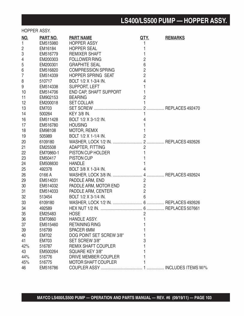
MAYCO LS400/LS500 PUMP — OPERATION AND PARTS MANUAL — REV. #6 (09/19/11) — PAGE 103
LS400/LS500 PUMP — HOPPER ASSY.HOPPER ASSY.
NO. PART NO. PART NAME QTY. REMARKS1 EM515980 HOPPER ASSY 12 EM16184 HOPPER SEAL 13 EM516779 REMIXER SHAFT 14 EM200303 FOLLOWER RING 25 EM200301 GRAPHITE SEAL 66 EM516820 COMPRESSION SPRING 27 EM514339 HOPPER SPRING SEAT 28 510717 BOLT 1/2 X 1-3/4 IN. 49 EM514338 SUPPORT, LEFT 110 EM514706 END CAP, SHAFT SUPPORT 111 EM902153 BEARING 212 EM200018 SET COLLAR 113 EM703 SET SCREW ............................................ 2 ................ REPLACES 49247014 500264 KEY 3/8 IN. 116 EM511428 BOLT 1/2 X 3-1/2 IN. 417 EM516780 HOUSING 118 EM98108 MOTOR, REMIX 119 505989 BOLT 1/2 X 1-1/4 IN. 220 6109180 WASHER, LOCK 1/2 IN. ........................... 2 ................ REPLACES 49262621 EM25508 ADAPTER, FITTING 222 EM70860-1 PISTON CUP HOLDER 123 EM50417 PISTON CUP 124 EM508830 HANDLE 125 492378 BOLT 3/8 X 1-3/4 IN. 426 0166 A WASHER, LOCK 3/8 IN. ........................... 4 ................ REPLACES 49262429 EM514031 PADDLE ARM, END 230 EM514032 PADDLE ARM, MOTOR END 231 EM514033 PADDLE ARM, CENTER 232 513454 BOLT 1/2 X 3-1/4 IN. 633 6109180 WASHER, LOCK 1/2 IN. ........................... 6 ................ REPLACES 49262634 492589 HEX NUT 1/2 IN. ...................................... 6 ................ REPLACES 50766135 EM25483 HOSE 236 EM70860 HANDLE ASSY. 137 EM515460 RETAINING RING 139 516799 SPACER 6MM 140 EM702 DOG POINT SET SCREW 3/8" 141 EM703 SET SCREW 3/8" 342% 516787 REMIX SHAFT COUPLER 143 EM500264 SQUARE KEY 3/8" 144% 516776 DRIVE MEMBER COUPLER 145% 516775 MOTOR SHAFT COUPLER 146 EM516786 COUPLER ASSY ...................................... 1 ................ INCLUDES ITEMS W/%

PAGE 104 — MAYCO LS400/LS500 PUMP — OPERATION AND PARTS MANUAL — REV. #6 (09/19/11)
LS400/LS500 PUMP — HOPPER ATTACHMENT ASSY.HOPPER ATTACHMENT ASSY.

MAYCO LS400/LS500 PUMP — OPERATION AND PARTS MANUAL — REV. #6 (09/19/11) — PAGE 105
LS400/LS500 PUMP — HOPPER ATTACHMENT ASSY.HOPPER ATTACHMENT ASSY.
NO. PART NO. PART NAME QTY. REMARKS1 EM514204 SPLASH PLATE 12 EM514620 HINGE PIN 13 EM491686 COTTER PIN 1/8 X 1-1/2 IN. 14 EM70134-2 PIN, SPLASH PLATE 15 EM505723 COTTER PIN 5/32 X 1-1/2 IN. 16 EM16166 TIE ROD 47 505728 NUT, HEX 1 IN. NC 128 EM14165 EYE BOLT 3/4 IN. 49 EM619 O-RING 3/4 IN. 410 EM968446 NUT, HEX 3/4 IN. 411 505121 BOLT 3/4 IN. X 3 IN. 412 EM968446 HEX NUT 3/4 IN. 413 505123 HEX BOLT 1/2 X 2-1/2 IN. 214 492491 HEX BOLT 1/2 X 1-1/2 IN. 115 6109160 HEX NUT 1/2 IN. ................................................ 3 .............REPLACES 49255616 492379 SCREW CAP 3/8" 217 3019092 WASHER FLAT 3/8" 418 515395 BOLT 7/16 NC X 4" G5 219 492584 NUT LOCK 1/2" 220 EM969013 NUT NYLOC 2

PAGE 106 — MAYCO LS400/LS500 PUMP — OPERATION AND PARTS MANUAL — REV. #6 (09/19/11)
LS400/LS500 PUMP — HOPPER INTERIOR ASSY.HOPPER INTERIOR ASSY.

MAYCO LS400/LS500 PUMP — OPERATION AND PARTS MANUAL — REV. #6 (09/19/11) — PAGE 107
LS400/LS500 PUMP — HOPPER INTERIOR ASSY.HOPPER INTERIOR ASSY.
NO. PART NO. PART NAME QTY. REMARKS1 EM16145A SWING AXLE BUSHING 22 EM284 STUD 1 IN. - 14 UNF 13 EM16175 O-RING 14 EM16170 RING SEAL, SHUTTLE AXLE 15 EM16176 O-RING 16 EM98022 WEAR RING HF 16A EM16816-1A RING, ENERGIZER RUBBER 17 EM16816-2 RING, INSERT STEEL 18 EM16804 SLEEVE 5 IN. ............................................ 1 ............... JUNE 2008 AND BELOW8 EM16804A SLEEVE 5 IN. ............................................ 1 ............... JULY 2008 AND ABOVE9 EM104 BOLT 5/8 X 2 IN. ........................................ 4 ............... REPLACES 50398210 EM923348 WASHER, LOCK 5/8 IN. 411 EM25803 DISCHARGE PLATE BEARING 112 EM98065 SEAL, RUBBER 113 EM512212 DISCHARGE NIPPLE 114 491701 GREASE FITTING 315 EM210 BOLT 5/8 X 2 IN. 617 EM16811 SHUTTLE CYLINDER 118 EM25843 NUN PLATE 119 EM104 BOLT, HEX HEAD 5/8 X 2 IN. .................... 4 ............... REPLACES 50398220 491719 PIN 121 EM923348 WASHER, LOCK 5/8 IN. 425 EM514357 HOPPER SCREEN 126 EM98021 PLATE, WEAR HF 127 EM969023 NUT, HEX 5/8 IN. NC INS. ......................... 2 ............... REPLACES 49258628 EM265 BOLT, COUNTER SUNK 5/8-11 x 3 IN. 229 EM923350 WASHER, LOCK 3/4 IN. ............................ 2 ............... REPLACES EM49262830 EM151 BOLT, HEX HEAD 3/4-10 X 2 IN. 231 EM264 BOLT, COUNTER SUNK 1/2-13 x 3 IN. 232 EM517700 O-RING 2

PAGE 108 — MAYCO LS400/LS500 PUMP — OPERATION AND PARTS MANUAL — REV. #6 (09/19/11)
LS400/LS500 PUMP — SHUTTLE CYLINDER ASSY.SHUTTLE CYLINDER ASSY.

MAYCO LS400/LS500 PUMP — OPERATION AND PARTS MANUAL — REV. #6 (09/19/11) — PAGE 109
LS400/LS500 PUMP — SHUTTLE CYLINDER ASSY.SHUTTLE CYLINDER ASSY.
NO. PART NO. PART NAME QTY. REMARKS1 EM16145 SWING AXLE BUSHING 22 EM510684 GREASE FITTING 13 EM16169 THRUST WASHER 14 EM25236 SHUTTLE CRANK, SPLINED SHAFT 15 EM505490 GREASE FITTING 26 EM16814 TENSIONER 17 EM424 HEX NUT 1 IN. 14NF 17A EM924006 COTTER PIN 5/32 X 2 IN. 18 EM417 NUT 1 IN. 14NF 19 EM98106 SHUTTLE CYLINDER ASSY. ....................... 1 ............ INCLUDES ITEMS W/*9A EM98106SK SEAL KIT, SHUTTLE CYLINDER 110* EM254549 BRACKET, PIVOT 111 492397 BOLT 1/2 X 2-1/2 IN. 412 EM621 WASHER 1/2 IN. 413 6109180 WASHER, LOCK 1/2 IN. ............................... 4 ............ REPLACES 49262614 492584 NUT 1/2 IN. 415* 0820270000 CLEVIS PIN 3/4 IN. 216* 0820270000 COTTER PIN 218* 515249 JAM NUT 119* 0509440000 FEMALE CLEVIS 220 3322 FITTING, ELBOW 221 EM514590 HOSE 122 EM514591 HOSE 123 517742 COVER, SHUTTLE CYLINDER 124 0202 BOLT ............................................................. 3 ............ REPLACES 49236425 EM923023 WASHER, FLAT ............................................ 3 ............ REPLACES 49259726 2105164 NUT, HEX ...................................................... 3 ............ REPLACES 492582

PAGE 110 — MAYCO LS400/LS500 PUMP — OPERATION AND PARTS MANUAL — REV. #6 (09/19/11)
LS400/LS500 PUMP — LUBRICATION PISTONS ASSY.LUBRICATION PISTONS ASSY.

MAYCO LS400/LS500 PUMP — OPERATION AND PARTS MANUAL — REV. #6 (09/19/11) — PAGE 111
LS400/LS500 PUMP — LUBRICATION PISTONS ASSY.LUBRICATION PISTONS ASSY.
NO. PART NO. PART NAME QTY. REMARKS1 EM510265 BOLT, HEX HEAD 3/8 NC X 3-1/2 IN., BLACK OXIDE G8 62 EM16464 FACE PLATE 23 EM16465 PISTON CUP SPACER 64 EM98050 CUP, PISTON- ORANGE 25 EM14408 RING, BRONZE 26 EM16493 RING, FELT 27 EM16462 FELT HOLDER 28 EM16461 OILER PLATE 29 EM14407 O- RING, OILER PLATE 210 EM25801 CYLINDER, CONCRETE 211 EM25110 RETAINER, CYLINDER 412 EM963610 BOLT, 3/8 NC X 1.3/4 IN. G5................................................... 8 ........ REPLACES 49237513 0166 A WASHER LOCK 3/8 IN. ..........................................................8 ........ REPLACES 49262414 3019092 WASHER, FLAT 3/8 IN. ......................................................... 22 ....... REPLACES 49259816 EM514197 LUBRICATION BOX 117 EM507895 PLUG 118 EM515796 COVER, LUBRICATION BOX 119 EM514610 LATCH, COVER 120 491754 RIVET, AM-66 221 492378 BOLT, 3/8 NC X 1.3/4 IN. G5 622 0166 A WASHER, LOCK 3/8” .............................................................. 6 ........ REPLACES 49262423 EM274351 SEAL LUBE BOX 224 EM50425 FLANGE, RING 225 492451 BOLT 3/8 - 24 X 1 IN. HEX HEAD 826 EM50443 SEAL, OIL BOX 827 514208 BAR,PROXIMITY SWITCH SUPPORT 128 EM98163 SWITCH, PROXIMITY W/CABLE 229 EM98135 CABLE HOUSING, FEMALE 230 EM98134 SEAL, CONNECTOR HOUSING 631 EM98138 TERMINAL PIN, FEMALE 632 514611 GROMMMET 233 504505 WRAP TIE 8

PAGE 112 — MAYCO LS400/LS500 PUMP — OPERATION AND PARTS MANUAL — REV. #6 (09/19/11)
LUBRICATION PISTONS ASSY.
LS400/LS500 PUMP — LUBRICATION PISTONS ASSY.

MAYCO LS400/LS500 PUMP — OPERATION AND PARTS MANUAL — REV. #6 (09/19/11) — PAGE 113
LS400/LS500 PUMP — LUBRICATION PISTONS ASSY.LUBRICATION PISTONS ASSY.
NO. PART NO. PART NAME QTY. REMARKS34 492366 BOLT, HEX HEAD 5/16 NC X 1 IN. G5 635 EM492623 WASHER, LOCK 5/16 IN. 436 EM514216 ADJUSTMENT ROD, PROXIMITY SWITCH 237 EM492556 NUT, HEX 1/2 IN. 438 EM514207 BRACKET, ADJUSTMENT ROD 239 EM492597 WASHER, FLAT 5/16 IN. 640 EM492582 NUT, HEX HEAD 5/16 IN 241 EM98211 CYLINDER, MAIN 242 EM514920 HOSE, MAIN HYD. CYLINDER 243 EM514202 EXTENSION, SPACER 244 EM185 BOLT, SOCKET HEAD 3/8 NC X 3 IN., BLACK OXIDE G8 645 EM25497 FITTING, 90° 446 EM25474 HOSE, HYDRAULIC SLAVE 147 EM16459 PIN, WRIST 248 EM505723 PIN, COTTER 449 EM491701 FITTING, GREASE 250 EM517126 LOCK WASHER 651 EM513352 SEAL, SQUARE 1

PAGE 114 — MAYCO LS400/LS500 PUMP — OPERATION AND PARTS MANUAL — REV. #6 (09/19/11)
LS400/LS500 PUMP — FUEL TANK ASSY.FUEL TANK ASSY.

MAYCO LS400/LS500 PUMP — OPERATION AND PARTS MANUAL — REV. #6 (09/19/11) — PAGE 115
LS400/LS500 PUMP — FUEL TANK ASSY.FUEL TANK ASSY.
NO. PART NO. PART NAME QTY. REMARKS1 EM514084 COVER, DIESEL TANK 42 514080 GASKET 43 492362 BOLT 5/16 X 5/8 IN. 564 EM923343 WASHER, LOCK 5/16 IN. .................................. 56 ......... REPLACES 4926235 34507 CAP, FUEL W\GAUGE 16 EM514559 ADAPTOR 17 506208 CLAMP 58 EM514536 HOSE, FUEL RETURN 5/16 IN. A/R9 EM20426 ADAPTER 110 EM514536 HOSE, FUEL FILTER 5/16 IN. A/R11 EM20763 FILTER, FUEL 2

PAGE 116 — MAYCO LS400/LS500 PUMP — OPERATION AND PARTS MANUAL — REV. #6 (09/19/11)
LS400/LS500 PUMP — HEAT EXCHANGER ASSY.HEAT EXCHANGER ASSY.

MAYCO LS400/LS500 PUMP — OPERATION AND PARTS MANUAL — REV. #6 (09/19/11) — PAGE 117
LS400/LS500 PUMP — HEAT EXCHANGER ASSY.HEAT EXCHANGER ASSY.
NO. PART NO. PART NAME QTY. REMARKS1 EM98118 HEAT EXCHANGER 12 EM514175 COVER, HEAT EXCHANGER 13 EM963610 BOLT 3/8 IN. X 1 IN. ........................... 4 ..............REPLACES 4923754 3019092 O-RING 3/8 IN. ................................... 4 ..............REPLACES 4925985 0166 A WASHER, LOCK 3/8 IN. ..................... 4 ..............REPLACES 4926246 0202 BOLT 5/16 X 1 IN. .............................. 4 ..............REPLACES 4923647 EM923023 WASHER, FLAT 5/16 IN. .................... 8 ..............REPLACES 4925978 2105164 NUT 5/16 IN. ....................................... 4 ..............REPLACES 4925829 EM25497 ADAPTER 110 EM514607 HOSE 4000 PSI 111 EM25566 ADAPTER 112 EM509345 ADAPTER 113 EM514606 HOSE 2000 PSI 114 EM509401 ADAPTER 115 EM514604 HOSE, 2000 PSI 116 EM98264 MOTOR AND FAN ASSY 1
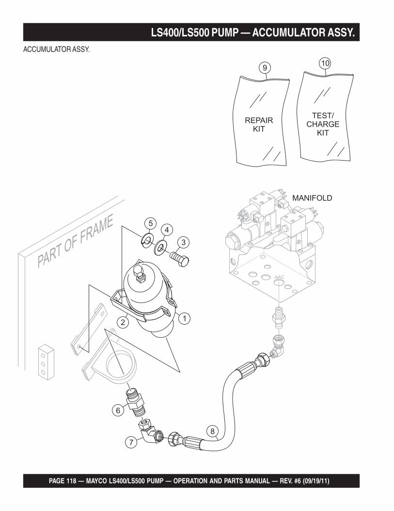
PAGE 118 — MAYCO LS400/LS500 PUMP — OPERATION AND PARTS MANUAL — REV. #6 (09/19/11)
LS400/LS500 PUMP — ACCUMULATOR ASSY.ACCUMULATOR ASSY.

MAYCO LS400/LS500 PUMP — OPERATION AND PARTS MANUAL — REV. #6 (09/19/11) — PAGE 119
LS400/LS500 PUMP — ACCUMULATOR ASSY.ACCUMULATOR ASSY.
NO. PART NO. PART NAME QTY. REMARKS1 EM97015 ACCUMULATOR 1 GAL. 12 EM97016 BRACKET, ACCUMULATOR 13 EM9603055 BOLT, HHCS 3/8 IN. DIA. 24 3019092 WASHER, FLAT 3/8 IN. 25 0166A WASHER, LOCK 3/8 IN. DIA. 26 EM509425 FITTING, STRAIGHT 17 EM509353 FITTING, 90° ELBOW 18 EM514603 HOSE, ACCUMULATOR 19 EM98009 ACCUMULATOR REPAIR KIT 110 EM98052 ACCUMULATOR TEST/CHARGE KIT 1

PAGE 120 — MAYCO LS400/LS500 PUMP — OPERATION AND PARTS MANUAL — REV. #6 (09/19/11)
LS400/LS500 PUMP — REMIXER CONTROL ASSY.REMIXER CONTROL ASSY.

MAYCO LS400/LS500 PUMP — OPERATION AND PARTS MANUAL — REV. #6 (09/19/11) — PAGE 121
LS400/LS500 PUMP — REMIXER CONTROL ASSY.REMIXER CONTROL ASSY.
NO. PART NO. PART NAME QTY. REMARKS1 EM25495 VALVE REMIXER W/ LEVER 12 515384 ADAPTER FITTING, T 13 506195 ADAPTER FITTING, 90° ELBOW 14 EM25509 ADAPTER FITTING, STRAIGHT 25 EM218 BOLT 5/16 X 2-1/2 IN. 26 EM923343 WASHER, LOCK 5/16 IN. .............................. 2 .................REPLACES 4926237 2105164 NUT, HEX 5/16 IN. ......................................... 2 .................REPLACES 4925538 EM98015 COUPLING 19 EM98014 TEST PORT 1

PAGE 122 — MAYCO LS400/LS500 PUMP — OPERATION AND PARTS MANUAL — REV. #6 (09/19/11)
GREASE POINTS
LS400/LS500 PUMP — LUBRICATION PANEL
POSITION LOCATION LENGTH OF LINESA ................................................. CLEVIS GREASE POINT ................................................ 34 in. (1.1 m)B ................................................. SWING AXLE BUSHING GREASE POINT ...................... 26 in. (.85 m)C................................................. PIVOT BRACKET GREASE POINT ................................. 41 in. (1.5 m)
Grease daily, two or three hots of #2multipurpose automotive grease. Overgreasing any bearing will not damagethe machine. ALWAYS grease beforeand after pump operation.

MAYCO LS400/LS500 PUMP — OPERATION AND PARTS MANUAL — REV. #6 (09/19/11) — PAGE 123
LS400/LS500 PUMP — LUBRICATION PANELLUBRICATION PANEL ASSY.
NO. PART NO. PART NAME QTY. REMARKS1 EM491701 GREASE FITTING 32 EM508812 CONNECTOR 23 EM510684 CONNECTOR 34 EM505516 HOSE, PLASTIC A/R5 EM510487 HOSE, STEEL 1

PAGE 124 — MAYCO LS400/LS500 PUMP — OPERATION AND PARTS MANUAL — REV. #6 (09/19/11)
ENGINE COVER ASSY.
LS400/LS500 PUMP — ENGINE COVER ASSY.

MAYCO LS400/LS500 PUMP — OPERATION AND PARTS MANUAL — REV. #6 (09/19/11) — PAGE 125
LS400/LS500 PUMP — ENGINE COVER ASSY.ENGINE COVER ASSY.
NO. PART NO. PART NAME QTY. REMARKS1 EM517737 COVER, TOP 12 492356 BOLT 1/4" NC X 3/4" G5 163 EM923057 LOCK WASHER 1/4 IN. ........................................14 ..........REPLACES 4925964 2101402 WASHER 1/4 IN. ..................................................16 ..........REPLACES 4926226 EM517730 COVER, FRONT ENGINE 17 492541 NUT 5/16" NC G2 28 TK6737260 DOCUMENT CYLINDER 1

PAGE 126 — MAYCO LS400/LS500 PUMP — OPERATION AND PARTS MANUAL — REV. #6 (09/19/11)
HYDRAULIC TANK ASSY.
LS400/LS500 PUMP — HYDRAULIC TANK ASSY.

MAYCO LS400/LS500 PUMP — OPERATION AND PARTS MANUAL — REV. #6 (09/19/11) — PAGE 127
LS400/LS500 PUMP — HYDRAULIC TANK ASSY.HYDRAULIC TANK ASSY.
NO. PART NO. PART NAME QTY. REMARKS1 514040 HYDRAULIC TANK, LS-S 13 0166 A LOCK, WASHER 3/8 IN. .......................................4 ...........REPLACES 4926244 EM517295 HANDLE 15 EM251191 TANK COVER PLATE 16 EM25184 RESERVOIR GASKET 17 492362 BOLT 5/16 X 5/8 IN. 208 EM923343 WASHER, LOCK 5/16 IN. .................................... 20 ..........REPLACES 4926239 EM98263 CAP ASSEMBLY 110 492267 BOLT 3/16 X 5/8 IN. 611 16433 TUBE 112 EM491189 FITTING 113 EM18436 90° MALE ADAPTER 2103-16-16 114 EM514605 HOSE 115 EM514622 FITTING 1 IN. 116 EM514597 HOSE 117 EM491164 ELBOW, 3/4 IN. 118 509784 ADAPTER 119 517002 HOSE 120 EM509369 STRAIGHT MALE ADAPTOR , 0101-08-08 121 491237 VALVE 1/2 IN. 122 506094 CAP 1/2 IN. 123 EM98188 GAUGE, LEVEL & TEMP. ..................................... 1 ...........REPLACES EM1647824 EM97066 GAUGE 3000PSI, ACCUMULATOR 125 EM97067 GAUGE 5000 PSI, MAIN 126 EM25523 ADAPTER 227 EM509517 HOSE, 4000 PSI MAIN GAUGE 128 EM514602 HOSE, 4000 PSI ACCUMULATOR GAUGE 129 EM16517 STRAIGHT MALE ADAPTER 0102-24-16 130 EM98112A RETURN FILTER ASSY. .......................................1 ...........S/N 281101 AND BELOW30A EM98275 ELEMENT, RETURN FILTER ................................1 ...........S/N 281102 AND ABOVE31 516814 90° FITTING 133 EM16513 DIFFUSER 134 492376 BOLT 3/8 X 1-1/4 IN. 435 492598 WASHER, FLAT 3/8 IN. 436 509343 TEE FITTING 141 TBD BOLT 245 516813 BUSHING 146 409401 ADAPTOR 3903-16-16 147 EM16414 VALVE NEEDLE 148 16516 PIPE 1-1/2" ...........................................................1 ...........S/N 281101 AND BELOW49 509344 ADAPTOR 063T-16-16 150 514604 HOSE 151 514604 HOSE 1

PAGE 128 — MAYCO LS400/LS500 PUMP — OPERATION AND PARTS MANUAL — REV. #6 (09/19/11)
LS-40TD/LS-50TD ENGINE ASSY.
LS400/LS500 PUMP — ENGINE ASSY.

MAYCO LS400/LS500 PUMP — OPERATION AND PARTS MANUAL — REV. #6 (09/19/11) — PAGE 129
LS400/LS500 PUMP — ENGINE ASSY.ENGINE ASSY.
NO. PART NO. PART NAME QTY. REMARKS1 EM98189 ENGINE, DEUTZ TURBO 76 HP BF4L2011 12 492401 BOLT1/2 IN.X 4 FT. 43 6109170 WASHER, FLAT 1/2 IN. ........................................... 4............ REPLACES 4926004 6109180 WASHER, LOCK 1/2 IN. ......................................... 4............ REPLACES 4926265 EM511021 AIR DUCTING CLAMP 26 EM510725 AIR DUCTING CLAMP 27 EM511019 AIR DUCTING DUCTING 18 TBD CLAMP 39 EM510888 CONNECTOR, AIR FILTER 110 22001301 HOSE, ELBOW 90° 111 22002183 AIR CLEANER ASSY. ............................................. 1............ INCLUDES ITEMS W/*12* 01881280 HOOD, AIR CLEANER 113* 01319257 INSERT, AIR FILTER 114* 01880870 CARTRIDGE, SAFETY AIR 115* 01881413 DUST EJECTOR 116* EM492366 BOLT 5/16 X 1-1/2 IN. 217* EM492623 WASHER, LOCK 5/16 IN. 218* EM492597 WASHER, FLAT 5/16 IN. 419* EM492553 NUT, HEX 5/16 IN. G5 224 EM514633 REDUCTION TUBE, EXHAUST 125 492371 BOLT 5/16 NC X 3 IN. G5 226 EM923023 WASHER, FLAT 5/16 IN. ......................................... 4............ REPLACES 49259727 EM514714 SPACER, EXHAUST 228 EM923343 WASHER, LOCK 5/16 IN. ........................................ 2............ REPLACES 49262329 2105164 HEX NUT 5/16 IN. G5.............................................. 2............ REPLACES 49255330 EM510897 CAP, EXHAUST 2-1/2 IN. 131 01174416 FILTER, OIL (ENGINE) 132 01174696 FILTER, FUEL (ENGINE) 133 EM516434 PIPE EXHAUST ASSY. 1

PAGE 130 — MAYCO LS400/LS500 PUMP — OPERATION AND PARTS MANUAL — REV. #6 (09/19/11)
THROTTLE ASSY.
LS400/LS500 PUMP — THROTTLE ASSY.

MAYCO LS400/LS500 PUMP — OPERATION AND PARTS MANUAL — REV. #6 (09/19/11) — PAGE 131
LS400/LS500 PUMP — THROTTLE ASSY.THROTTLE ASSY.
NO. PART NO. PART NAME QTY. REMARKS1 510792 SUPPORT 12 492356 BOLT 1/4' X 3/4 IN. 33 EM167 BOLT 1/4 X 1-3/4 IN. 44 EM923057 LOCK WASHER 1/4 IN. ..................................... 4 .............. REPLACES 4925965 2101402 WASHER 1/4 IN. ............................................... 4 .............. REPLACES 4926226 EM16465 PISTON SPACER 27* EM98233 BLOCK 18* EM98228 COIL, 12V 19* EM98232 VALVE 110 EM25429 ELBOW ADAPTER 90° MALE 311 EM25511 STRAIGHT ADAPTER 112 EM25576 HOSE 20 IN. 213 EM50449 ELBOW ADAPTER 90° MALE 114 EM25504 ELBOW ADAPTER 90° MALE 115 EM50463 HOSE 17-1/2 IN. 116 EM50449 ELBOW ADAPTER 90° MALE 117 EM50462 HOSE 10 IN. 118 EM50449 ELBOW ADAPTER 90° MALE 119 EMCC700 HYDRAULIC CYLINDER 120 492581 NUT, HEX 1/4 IN. 221 515812 THROTLE CONTROL PLATE 122 513213 THROTTLE CABLE GUIDE 123 EM501102 SLEEVE, THROTTLE 124 EM491089 BOLT 8 X 1/4 IN. 125 510229 CABLE, THROTTLE 126 492366 BOLT 5/16 X 1-1/2 IN. 127 2105164 HEX NUT 5/16 IN. ............................................. 1 .............. REPLACES 49255328 EM98168 THROTTLE BLOCK ASSY. ............................... 1 .............. INCLUDES ITEMS W/*

PAGE 132 — MAYCO LS400/LS500 PUMP — OPERATION AND PARTS MANUAL — REV. #6 (09/19/11)
WATER SEPARATOR ASSY.
LS400/LS500 PUMP — WATER SEPARATOR ASSY.

MAYCO LS400/LS500 PUMP — OPERATION AND PARTS MANUAL — REV. #6 (09/19/11) — PAGE 133
LS400/LS500 PUMP — WATER SEPARATOR ASSY.WATER SEPARATOR ASSY.
NO. PART NO. PART NAME QTY. REMARKS1 514340 BRACKET, WATER SEPARATOR 12 TBD BOLT 23 EM16747 WATER SEPARATOR ASSEMBLY 13A P53712 CARTRIDGE, WATER SEPARATOR 14 492364 BOLT 5/16 X 1 IN. 35 2105164 HEX NUT 5/16 IN. ............................................. 3 .............. REPLACES 4925826 EM514559 ELBOW ADAPTER 90° MALE 27 EM506208 CLAMP, HOSE 28 EM514536 HOSE 5/16 IN. TBD

PAGE 134 — MAYCO LS400/LS500 PUMP — OPERATION AND PARTS MANUAL — REV. #6 (09/19/11)
HYDRAULIC PUMP ASSY.
LS400/LS500 PUMP — HYD. PUMP ASSY.

MAYCO LS400/LS500 PUMP — OPERATION AND PARTS MANUAL — REV. #6 (09/19/11) — PAGE 135
LS400/LS500 PUMP — HYD. PUMP ASSY.HYDRAULIC PUMP ASSY.
NO. PART NO. PART NAME QTY. REMARKS1* TBD O-RING 12 EM514719 FLANGE, SUCTION PIPE .......................................... 2 ............ INCLUDES ITEMS W/*3 EM492444 BOLT 1/2 X 1-1/4 IN. 44 6109180 WASHER, LOCK 1/2 IN. .............................................. 6 ............ REPLACES 4926265 EM514718 SUCTION PIPE ADAPTER, 40 SPECIAL 16 EM515207 CLAMP 2 IN. ................................................................ 27 EM514623 HOSE, SUCTION 2 IN. 18 EM514627 ADAPTER, SUCTION PIPE 32 19 EM514628 FLANGE, SUCTION PIPE .......................................... 1 ............ INCLUDES ITEMS W/%10 EM510902 BOLT 1/2 X 1-1/2 IN. 411 6109180 WASHER, LOCK 1/2 IN. .............................................. 4 ............ REPLACES 49262612% O-RING 113 EM98128 COUPLER, ENGINE ASSY. 114 EM510902 BOLT 1/2 X 1-1/2 IN. 216 EM517674 PUMP, MAIN 60CC, PARKER P1-60 SERIES ............ 1 ............ USED ON LS400 ONLY16 EM98256 PUMP, MAIN 75CC, PARKER P1-75 SERIES ............ 1 ............ USED ON LS500 ONLY17 EM98273 FLOW CONTROL VALVE 118 EM506953 BOLT 7/16 X 3 IN. 419 EM16190 GASKET 120 EM98107 PUMP, SECONDARY 121 EM963610 BOLT 3/8 X 1 IN. .......................................................... 2 ............ REPLACES 49237522 0166 A WASHER, LOCK 3/8 IN. .............................................. 2 ............ REPLACES 49262423 EM25498 STRAIGHT ADAPTER 124 EM25429 ELBOW ADAPTER 125 EM514599 HOSE, 4000 PSI SENSOR ......................................... 1 ............ USED ON LS400 ONLY25 EM516875 HOSE, 4000 PSI SENSOR ......................................... 1 ............ USED ON LS500 ONLY26 EM25429 ELBOW ADAPTER 127 EM491372 STRAIGHT ADAPTER 129 EM25498 STRAIGHT ADAPTER 130 EM16524 ELBOW ADAPTER 90° MALE 231 506200 ELBOW ADAPTER 132 EM514601 HOSE 2000 PSI, REMIX VALVE 133 EM517649 MOTORIZED FLOW CONTROL MANIFOLD ASSY. 134 EM517038 HOSE, MAIN MANIFOLD 135 EM509353 ELBOW 136$ TBD VALVE, MAIN RELIEF 137 EM514608 HOSE 139 EM25459 ELBOW 140 EM25429 ELBOW ADAPTER 1

PAGE 136 — MAYCO LS400/LS500 PUMP — OPERATION AND PARTS MANUAL — REV. #6 (09/19/11)
MANIFOLD ASSY.
LS400/LS500 PUMP — MANIFOLD ASSY.
FRONT OFMACHINE
21
20
B2A2
T3
9
17
1
2
13
14
15
16
18
18
1919
1414
16
23
3
T1
B1A1
6
7
5
10
12
T2P2
P1
AAC
GA
2422
23
22
23
25
4
12A
8

MAYCO LS400/LS500 PUMP — OPERATION AND PARTS MANUAL — REV. #6 (09/19/11) — PAGE 137
LS400/LS500 PUMP — MANIFOLD ASSY.MANIFOLD ASSY.
NO. PART NO. PART NAME QTY. REMARKS1 EM963102 BOLT 1/2 X 1-1/4 IN. ................................................ 4 .......... REPLACES 4923932 6109180 WASHER, LOCK 1/2 IN. ........................................... 4 .......... REPLACES 4926263 EM98261 MANIFOLD ASSY COMPLETE ............................... 1 .......... REPLACES EM98109
............................................................................................... INCLUDES ITEMS W/ %4% EM98220 CYCLING VALVE, SWING W/PILOTS ...................... 1 .......... INCLUDES ITEMS W/ #5# EMBK227 BOLT, SHCS 1/2" x 2-1/4" 126# EM98223 PILOT VALVE, SHUTTLE 17# EMBK2097 BOLT, SHCS 1/2" X 1-1/4" 88 EM98221 CYCLING VALVE, MAIN ........................................... 1 .......... INCLUDES ITEM W/ &9& EM98222 PILOT VALVE, MAIN CYLINDER 110% EM98227 CHECK VALVE 112% EM98228 COIL, 12VDC ACCUMULATOR 112A% EM98229 ACCUMULATOR UNLOADER CARTRIDGE ASSY 113 EM25498 ADAPTER 114 EM509401 ADAPTER 315 EM514488 ADAPTER 116 EM25459 ADAPTER 217 EM98226 UNLOADING RELIEF VALVE, SHUTTLE 118 EM514231 ADAPTER 219 EM514489 ADAPTER 220 EM491372 ADAPTER 121 506193 ADAPTER 122 EM25462 ADAPTER 223 EM509353 ADAPTER 324 EM25429 ADAPTER 125 TBD CHECK VALVE 1

PAGE 138 — MAYCO LS400/LS500 PUMP — OPERATION AND PARTS MANUAL — REV. #6 (09/19/11)
CONTROL BOX ASSY.
LS400/LS500 PUMP — CONTROL BOX ASSY.
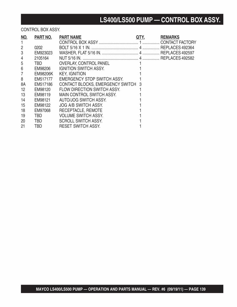
MAYCO LS400/LS500 PUMP — OPERATION AND PARTS MANUAL — REV. #6 (09/19/11) — PAGE 139
LS400/LS500 PUMP — CONTROL BOX ASSY.CONTROL BOX ASSY.
NO. PART NO. PART NAME QTY. REMARKS1 CONTROL BOX ASSY ..................................... 1 ................ CONTACT FACTORY2 0202 BOLT 5/16 X 1 IN. ............................................ 4 ................ REPLACES 4923643 EM923023 WASHER, FLAT 5/16 IN. .................................. 4 ................ REPLACES 4925974 2105164 NUT 5/16 IN. .................................................... 4 ................ REPLACES 4925825 TBD OVERLAY, CONTROL PANEL 16 EM98206 IGNITION SWITCH ASSY. 17 EM98206K KEY, IGNITION 18 EM517177 EMERGENCY STOP SWITCH ASSY. 18A EM517186 CONTACT BLOCKS, EMERGENCY SWITCH 312 EM98120 FLOW DIRECTION SWITCH ASSY. 113 EM98119 MAIN CONTROL SWITCH ASSY. 114 EM98121 AUTO/JOG SWITCH ASSY. 115 EM98122 JOG A/B SWITCH ASSY. 118 EM97068 RECEPTACLE, REMOTE 119 TBD VOLUME SWITCH ASSY. 120 TBD SCROLL SWITCH ASSY. 121 TBD RESET SWITCH ASSY. 1

PAGE 140 — MAYCO LS400/LS500 PUMP — OPERATION AND PARTS MANUAL — REV. #6 (09/19/11)
CONTROL BOX HARNESSES ASSY.
LS400/LS500 PUMP — CONTROL BOX HARNESSES ASSY.

MAYCO LS400/LS500 PUMP — OPERATION AND PARTS MANUAL — REV. #6 (09/19/11) — PAGE 141
LS400/LS500 PUMP — CONTROL BOX HARNESSES ASSY.CONTROL BOX HARNESSES ASSY.
NO. PART NO. PART NAME QTY. REMARKS1 EM514635 WIRE HARNESS 1 12 344102000 FUSE, 30 AMP 13 EM514636 WIRE HARNESS 2 14 EM514637 WIRE HARNESS 3 15 EM514638 WIRE HARNESS 4 16 509588 POLY FLEX TUBE 1/2 IN. BLACK AR7 16716 CONDUCTIVE DIVIDER 3/8 IN. AR

PAGE 142 — MAYCO LS400/LS500 PUMP — OPERATION AND PARTS MANUAL — REV. #6 (09/19/11)
REMOTE CONTROL CABLE ASSY.
LS400/LS500 PUMP — REMOTE CONTROL CABLE ASSY.

MAYCO LS400/LS500 PUMP — OPERATION AND PARTS MANUAL — REV. #6 (09/19/11) — PAGE 143
LS400/LS500 PUMP — REMOTE CONTROL CABLE ASSY.REMOTE CONTROL CABLE ASSY.
NO. PART NO. PART NAME QTY. REMARKS1* EM16753 JUNCTION BOX 12* EM16754 SWITCH 12A EM97075 SWITCH 13* EM491897 CONNECTOR, RING 3/16 IN. 44* EM16756 GUARD SWITCH - ALUMINUM 25* EM26791 SEAL, GRIP CORD 16* EM26790 CORD, MX P/E 25 FT. 17 EM26793 ADAPTER, CORD GRIP 1/2 IN. 18 EM97065 ADAPTER, CORD 100 FT. 19 EM97099 COMPLETE CORD ASSY 25 FT .............. 1 ................ INCLUDES ITEMS W/*

PAGE 144 — MAYCO LS400/LS500 PUMP — OPERATION AND PARTS MANUAL — REV. #6 (09/19/11)
LS400/LS500 PUMP — HYDRAULIC STABILIZER ASSY. (OPTIONAL)

MAYCO LS400/LS500 PUMP — OPERATION AND PARTS MANUAL — REV. #6 (09/19/11) — PAGE 145
LS400/LS500 PUMP — HYDRAULIC STABILIZER ASSY. (OPTIONAL)OPTIONAL HYDRAULIC STABILIZER ASSY.
NO. PART NO. PART NAME QTY. REMARKS1 TBD BOLT 22 TBD WASHER 23 TBD NUT 24 EM98046 VALVE REMIXER W/ 3 LEVERS 14A EM98047 HANDLE, DIRECTIONAL VALVE 35 506200 FITTING 45° 56 517101 HOSE 17 517102 HOSE 18 517103 HOSE 19 517104 HOSE 110 512655 FITTING 90° 711 25509 FITTING STRAIGHT 312 EM516382 HYDRAULIC STABILIZER 213 517107 FITTING STRAIGHT 114 517105 HOSE 115 517100 HOSE 216 517106 HOSE 117 517153 BOLT 218 517154 BOLT 219 490957 SNAP RING 8

PAGE 146 — MAYCO LS400/LS500 PUMP — OPERATION AND PARTS MANUAL — REV. #6 (09/19/11)
PAYMENT TERMSTerms of payment for parts are net 30 days.
FREIGHT POLICYAll parts orders will be shipped collect or prepaid with the charges added to the invoice. All shipments are F.O.B. point of origin. Multiquip’s responsibility ceases when a signed manifest has been obtained from the carrier, and any claim for shortage or damage must be settled between the consignee and the carrier.
MINIMUM ORDERThe minimum charge for orders from Multiquip is $15.00 net. Customers will be asked for instructions regarding handling of orders not meeting this requirement.
RETURNED GOODS POLICYReturn shipments will be accepted and credit will be allowed, subject to the following provisions:
A Returned Material Authorization 1. must be approved by Multiquip prior to shipment.
To obtain a Return Material Authorization, 2. a list must be provided to Multiquip Parts Sales that defines item numbers, quantities, and descriptions of the items to be returned.
The parts numbers and descriptions a. must match the current parts price list.
The list must be typed or computer b. generated.
The list must state the reason(s) c. for the return.
The list must reference the sales d. order (s) or invoice (s) under which the items were originally purchased.
The list must include the name e. and phone number of the person requesting the RMA.
A copy of the Return Material Authorization 3. must accompany the return shipment.
Freight is at the sender’s expense. All 4. parts must be returned freight prepaid to Multiquip’s designated receiving point.
Parts must be in new and resalable 5. condition, in the original Multiquip package (if any), and with Multiquip part numbers clearly marked.
The following items are not returnable:6.
Obsolete parts. (If an item is in the a. price book and shows as being replaced by another item, it is obsolete.)
Any parts with a limited shelf life b. (such as gaskets, seals, “O” rings, and other rubber parts) that were purchased more than six months prior to the return date.
Any line item with an extended c. dealer net price of less than $5.00.
Special order items.d.
Electrical components.e.
Paint, chemicals, and lubricants.f.
Decals and paper products.g.
Items purchased in kits.h.
The sender will be notified of any material 7. received that is not acceptable.
Such material will be held for five 8. working days from notification, pending instructions. If a reply is not received within five days, the material will be returned to the sender at his expense.
Credit on returned parts will be issued 9. at dealer net price at time of the original purchase, less a 15% restocking charge.
In cases where an item is accepted, for 10. which the original purchase document can not be determined, the price will be based on the list price that was effective twelve months prior to the RMA date.
Credit issued will be applied to future 11. purchases only.
PRICING AND REBATESPrices are subject to change without prior notice. Price changes are effective on a specific date and all orders received on or after that date will be billed at the revised price. Rebates for price declines and added charges for price increases will not be made for stock on hand at the time of any price change.
Multiquip reserves the right to quote and sell direct to Government agencies, and toOriginal Equipment Manufacturer accounts who use our products as integral parts of their own products.
SPECIAL EXPEDITING SERVICEA $35.00 surcharge will be added to the invoice for special handling including busshipments, insured parcel post or in cases where Multiquip must personally deliver the parts to the carrier.
LIMITATIONS OF SELLER’S LIABILITYMultiquip shall not be liable hereunder fordamages in excess of the purchase price of the item with respect to which damages are claimed, and in no event shall Multiquip be liable for loss of profit or good will or for any other special, consequential or incidental damages.
LIMITATION OF WARRANTIESNo warranties, express or implied, are made in connection with the sale of parts or trade accessories nor as to any engine not manufactured by Multiquip. Such warranties made in connection with the sale of new, complete units are made exclusively by a statement of warranty packaged with such units, and Multiquip neither assumes nor authorizes any person to assume for it any other obligation or liability whatever in connection with the sale of its products. Apart from such written statement of warranty, there are no warranties, express, implied or statutory, which extend beyond the description of the products on the face hereof.
Effective: February 22, 2006
TERMS AND CONDITIONS OF SALE — PARTS

MAYCO LS400/LS500 PUMP — OPERATION AND PARTS MANUAL — REV. #6 (09/19/11) — PAGE 147
MAYCO PUMP WARRANTYMECHANICAL DRIVE MODELS
MAYCO PUMP, hereinafter referred to as “Manufacturer’, warrants each new Mayco Pump sold by the manufacturer to be free from defects in material and workmanship, under normal use and service, for a period of one year after the date of delivery to the original retail purchaser. Manufacturer will, at its option, replace or repair at a point designated by the Manufacturer any part or parts which shall appear to the satisfaction of the Manufacturer upon inspection at such point to have been defective in material or workmanship. This warranty does not obligate the Manufacturer to bear any transportation charges or labor charges in connection with the replacement or repair the of the defective parts.
This warranty does not apply to any pump if attempts have been made to pump concrete materials which have separated, to any pump which has been repaired with other than Genuine Mayco Parts, nor to any pump which has been altered, repaired or used in such manner as to adversely affect its performance, nor to normal service or maintenance or where blockages have developed within the pump manifold or placing line or which has been operated in any other manner not recommended by the Manufacturer. Due to the abrasive nature of concrete, Mayco does not cover natural component wear.
THIS WARRANTY AND MANUFACTURER’S OBLIGATION HEREUNDER, IS IN LIEU OF ALL OTHER WARRANTIES, EXPRESS, IMPLIED OR STATUTORY AND ALL OTHER OBLIGATIONS OR LIABILITIES INCLUDING SPECIAL OR CONSEQUENTIAL DAMAGES OR CONTINGENT LIABILITIES ARISING OUT OF THE FAILURE OF ANY PUMP OR PART TO OPERATE PROPERLY, INCLUDING ANY WARRANTIES OF MERCHANTABILITY OR FITNESS FOR A PARTICULAR PURPOSE.
HYDRAULIC DRIVE MODELS
MAYCO PUMP, hereinafter referred to as “Manufacturer”, warrants each new Mayco Pump sold by the manufacturer to be free from defects in material and workmanship, under normal use and service, for a period of one year or 2000 hours after the date of delivery to the original retail purchaser. The Manufacturer will, at its option, replace or repair at a point designated by Manufacturer any part or parts which shall appear to the satisfaction of Manufacturer upon inspection at such point to have been defective in material or workmanship. This warranty does not obligate Manufacturer to bear any transportation charges or labor charges in connection with the replacement or repair of the defective parts.
This warranty does not apply to any pump if attempts have been made to pump concrete materials which have separated, to any pump which has been repaired with other than Genuine Mayco Parts, nor to any pump whichhas been altered, repaired or used in such manner as to adversely affect it’s performance, nor to normal service or maintenance or where blockages have developed within thepump manifold or placing line or which has been operatedin any other manner not recommended by the Manufacturer. Due to the abrasive nature of concrete, Mayco does not cover natural component wear.
THIS WARRANTY AND MANUFACTURER’S OBLIGATION HEREUNDER, IS IN LIEU OF ALL OTHER WARRANTIES, EXPRESS, IMPLIED OR STATUTORY AND ALL OTHEROBLIGATIONS OR LIABILITIES INCLUDING SPECIAL OR CONSEQUENTIAL DAMAGES OR CONTINGENT LIABILITIES ARISING OUT OF THE FAILURE OF ANY PUMP OR PART TO OPERATE PROPERLY, INCLUDINGANY WARRANTIES OF MERCHANTABILITY OR FITNESS FOR A PARTICULAR PURPOSE.

OPERATION AND PARTS MANUAL
Your Local Dealer is:
HERE’S HOW TO GET HELPPLEASE HAVE THE MODEL AND SERIAL
NUMBER ON-HAND WHEN CALLING
UNITED STATESMultiquip Corporate Office MQ Parts Department
18910 Wilmington Ave.Carson, CA 90746 Contact: [email protected]
Tel. (800) 421-1244Fax (800) 537-3927
800-427-1244310-537-3700
Fax: 800-672-7877Fax: 310-637-3284
Service Department Warranty Department
800-421-1244310-537-3700
Fax: 310-537-4259 800-421-1244310-537-3700
Fax: 310-943-2249
Technical Assistance
800-478-1244 Fax: 310-943-2238
MEXICO UNITED KINGDOM
MQ Cipsa Multiquip (UK) Limited Head Office
Carr. Fed. Mexico-Puebla KM 126.5Momoxpan, Cholula, Puebla 72760 MexicoContact: [email protected]
Tel: (52) 222-225-9900Fax: (52) 222-285-0420
Unit 2, Northpoint Industrial Estate, Globe Lane,Dukinfield, Cheshire SK16 4UJContact: [email protected]
Tel: 0161 339 2223 Fax: 0161 339 3226
CANADA
Multiquip
4110 Industriel Boul.Laval, Quebec, Canada H7L 6V3Contact: [email protected]
Tel: (450) 625-2244 Tel: (877) 963-4411Fax: (450) 625-8664
© COPYRIGHT 2011, MULTIQUIP INC.
Multiquip Inc, the MQ logo and the Mayco logo are registered trademarks of Multiquip Inc. and may not be used, reproduced, or altered without written permission. All other trademarks are the property of their respective owners and used with permission.
This manual MUST accompany the equipment at all times. This manual is considered a permanent part of the equipment and should remain with the unit if resold.
The information and specifications included in this publication were in effect at the time of approval for printing. Illustrations, descriptions, references and technical data contained inthis manual are for guidance only and may not be considered as binding. Multiquip Inc. reserves the right to discontinue or change specifications, design or the information published in this publication at any time without notice and without incurring any obligations.