concrete manholes -...
TRANSCRIPT

www.shawpipe.com
CONCRETE MANHOLES
S H A W P I P E P R O D U C T G U I D E A N D T E C H N I C A L R E F E R E N C E M A N U A L
CONCRETE PIPE SECTION 3
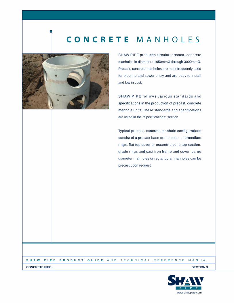
SHAW PIPE produces circular, precast, concrete
manholes in diameters 1050mmØ through 3000mmØ.
Precast, concrete manholes are most frequently used
for pipeline and sewer entry and are easy to install
and low in cost.
S H AW P I P E fo l l o w s va r i o u s s t a n d a r d s a n d
specifications in the production of precast, concrete
manhole units. These standards and specifications
are listed in the "Specifications" section.
Typical precast, concrete manhole configurations
consist of a precast base or tee base, intermediate
rings, flat top cover or eccentric cone top section,
grade rings and cast iron frame and cover. Large
diameter manholes or rectangular manholes can be
precast upon request.
C O N C R E T E M A N H O L E S
www.shawpipe.com

MA
NH
OL
ES
S H A W P I P E P R O D U C T G U I D E A N D T E C H N I C A L R E F E R E N C E M A N U A L
CONCRETE MANHOLES SECTION 3
www.shawpipe.com
GENERAL INFO
Once this information has been received, astandard shop drawing form is filled out for eachmanhole in the project.
First, the total height of the manhole (laid height)is determined, by calculating the difference inelevation between the top of concrete cover andthe lowest pipe invert (or bottom of sump). Thetop of concrete cover elevation is typically set as300mm below finished grade, to provide anallowance for final grade adjustment once themanhole has been installed.
Next, the pipe angles, size and type are determinedand laid out. Angles and pipe inverts are checkedto ensure sufficient clearance between adjacentpipes. All angles are measured clockwise fromthe outlet opening which is taken to be 0 degrees.For a manhole with two or more inlet pipes, theangle for each pipe relative to the outlet isdetermined.
Next, the distance to the center of each pipeopening is determined ( + to CL). All distances aremeasured from the outside bottom of the manholesection in which the opening is located. Typicallyall openings are in the base section, unless thereis a large change in elevation between pipes. Ifthis is the case, the height of the base section,and intermediate sections will be adjusted toensure that there is sufficient clearance betweenthe opening and the manhole joints.
Finally, the manhole sections are selected andlisted, giving the laid height of each piece andany special requirements for each section.Opening types are listed for each pipe, and anyspecial instructions are noted.
Unless otherwise specified, shop drawings aresent to the contractor for review and approval bythe project engineer. Any revisions required bythe engineer or contractor are made, then thefinal approved shop drawings are issued to ourproduction staff for fabrication.
To manufacture a manhole for a specific project,certain information is required to develop shopdrawings which are used by our production andshipping staff to manufacture and deliver theappropriate pieces which make up the manhole.
Information which is necessary to develop a shopdrawing normally comes from a set of engineeringdrawings containing a plan and profile of the sewerline. The minimum amount of information todetermine required manhole layout:
• Finished Grade Elevation (or top of concretecover if manhole extends above grade)
• Size and type of pipe entering the manhole(nominal diameter and pipe material)
• All pipe inverts (elevation at inside bottom of thepipe taken at the manhole wall)
• Angles between piping (measured clockwisefrom the outlet pipe which is taken as 0°)
• Size of manhole (nominal inside diameter)
Additional information which should beprovided would include:
• Sump depth (if required)• Base configuration (with or without benching, with
or without bottom slab)• Opening type (water tight rubber gasket, smooth
or rough cut hole, doghouse opening.)• Gasket type for joints / confined rubber o-ring,
“Ram-Nek” butyl rubber strip, no gasket• Special allowances for grade adjustment• Type of access hatch or cover to be used (cast iron
frame and cover, aluminum access hatch, etc.)• Size and location of access opening in
concrete cover• Special items to be cast into manhole sections
(lifting davits, access frames, tie downs)
How to Read SHAW PIPEManhole Shop Drawings
1
RE
F-2
4/25
-12/
06
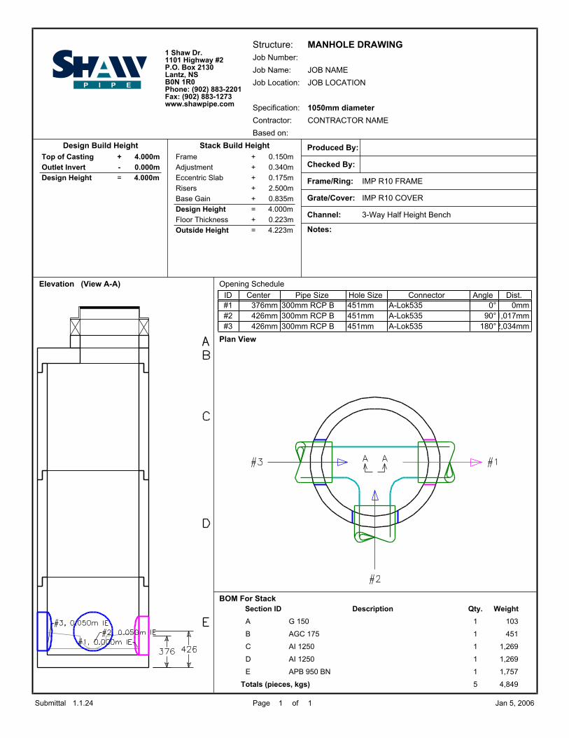
Structure:Job Number:
Job Name:
Job Location:
Specification:
Contractor:
MANHOLE DRAWING
JOB NAME
JOB LOCATION
1050mm diameter
CONTRACTOR NAME
Produced By:
Checked By:
Frame/Ring: IMP R10 FRAME
Grate/Cover: IMP R10 COVER
Channel: 3-Way Half Height Bench
Notes:
Elevation (View A-A) Opening Schedule
Plan View
BOM For Stack
Based on:
Design Build Height Stack Build HeightFrame + 0.150m
Adjustment + 0.340m
Eccentric Slab + 0.175m
Risers + 2.500m
Base Gain + 0.835m
Design Height = 4.000m
Floor Thickness + 0.223m
Outside Height = 4.223m
Top of Casting + 4.000m
Outlet Invert - 0.000m
Design Height = 4.000m
Dist.AngleConnectorHole SizePipe SizeCenterID0mm0°A-Lok535451mm300mm RCP B376mm#1
1,017mm90°A-Lok535451mm300mm RCP B426mm#22,034mm180°A-Lok535451mm300mm RCP B426mm#3
Section ID Description Qty. Weight
A G 150 1 103
B AGC 175 1 451
C AI 1250 1 1,269
D AI 1250 1 1,269
E APB 950 BN 1 1,757
Totals (pieces, kgs) 5 4,849
1.1.24 Page 1 of 1 Jan 5, 2006Submittal
1 Shaw Dr.1101 Highway #2P.O. Box 2130Lantz, NSB0N 1R0Phone: (902) 883-2201Fax: (902) 883-1273www.shawpipe.com

MA
NH
OL
ES
S H A W P I P E P R O D U C T G U I D E A N D T E C H N I C A L R E F E R E N C E M A N U A L
CONCRETE MANHOLES SECTION 3
www.shawpipe.com
GENERAL INFO
3
MANHOLE DIAMETER SELECTION GUIDE
1200mm DIAMETER MANHOLES
1050mm DIAMETER MANHOLES
RE
F-2
6-12
/06
525mmØ
125°
525mmØAlok #850
Alok #850
110°
450mmØ
450mmØAlok #740
Alok #740
90°
375mmØ
375mmØAlok #640
Alok #640
115°
600mmØ
600mmØAlok #970
Alok #970
450mmØ
450mmØ
90°
Alok #740
Alok #740
525mmØ
525mmØ
110°
Alok #850
Alok #850

GENERAL INFO
S H A W P I P E P R O D U C T G U I D E A N D T E C H N I C A L R E F E R E N C E M A N U A L
CONCRETE MANHOLES SECTION 3
www.shawpipe.com
MA
NH
OL
ES
MANHOLE DIAMETER SELECTION GUIDE
1500mm DIAMETER MANHOLES
1800mm DIAMETER MANHOLES
2100mm DIAMETER MANHOLES
RE
F-2
8-03
/09
4
900mmØ
135°Alok #1470
900mmØAlok #1470
110°
750mmØ
750mmØ
Alok #1200
Alok #1200
90°
600mmØ
600mmØ
Alok #970
Alok #970
90°
750mmØ
750mmØ
Alok #1200
Alok #1200
110°
900mmØ
900mmØ
Alok #1470
Alok #1470
1050mmØ
1050mmØ
115°
Alok #1640
Alok #1640
90°
900mmØ
900mmØ
Alok #1470
Alok #1470
110°
1050mmØ
1050mmØ
Alok #1640
Alok #16401200mmØ
1200mmØAlok #1860
Alok #1860
115°

MA
NH
OL
ES
S H A W P I P E P R O D U C T G U I D E A N D T E C H N I C A L R E F E R E N C E M A N U A L
CONCRETE MANHOLES SECTION 3
www.shawpipe.com
GENERAL INFO
5
MANHOLE DIAMETER SELECTION GUIDE
RE
F-2
8-03
/09
2400mm DIAMETER MANHOLES
3000mm DIAMETER MANHOLES
110°
1370mmØ
1370mmØ
Alok #2040
Alok #2040
1500mmØAlok #2300
135°
Alok #23001500mmØ
Alok #23001500mmØ
115°
1500mmØAlok #2300
Alok #18601200mmØ
90°
Alok #18601200mmØ
110°
1370mmØ
1370mmØ
Alok #2040
Alok #2040
110°
1200mmØ
1200mmØ
Alok #1860
Alok #1860
Alok #16401050mmØ
90°
Alok #16401050mmØ

GENERAL INFO
S H A W P I P E P R O D U C T G U I D E A N D T E C H N I C A L R E F E R E N C E M A N U A L
CONCRETE MANHOLES SECTION 3
www.shawpipe.com
MA
NH
OL
ES
6
A-LOK GASKET CONNECTION
STANDARD HOLE w/GROUTEDCONNECTION
DOGHOUSE OPENINGw/ GROUTED CONNECTION
STANDARD PIPE CONNECTIONS
GroutNon-Shrink
+ to
CL
Pipe O.D. + 50mm Min.
+ to
CL
+ to
CL
Cast-in-PlaceBase Slab
Pipe O.D. + 50mm Min.
Existing pipe
Non Shrink Grout
150mm Min.
Hei
ght
RE
F-3
0-12
/06

MA
NH
OL
ES
S H A W P I P E P R O D U C T G U I D E A N D T E C H N I C A L R E F E R E N C E M A N U A L
CONCRETE MANHOLES SECTION 3
www.shawpipe.com
GENERAL INFO
Typical Mono Base
RE
F-3
7-12
/06
Wall, bottom, and benching cast as a single unit.Mono Bases are designed to provide cost efficienciesin standard sanitary sewer applications. Wherepossible, designers should specify mono bases.
• Inside Diameter: 1067mm• Wall Thickness: 114mm• Drop across Manhole: 38mm
Available with in-wall A-LOK gasket connection only.
Manufactured for the following nominal pipe sizes:• 200mm PVC SDR 35• 250mm PVC SDR 35
Base Section: APB 500 MonoLaid Height (mm): 500Weight (kg): 1370
7
1067mm I.D 114mm
BaseHeight
ABP 500 Mono

GENERAL INFO
S H A W P I P E P R O D U C T G U I D E A N D T E C H N I C A L R E F E R E N C E M A N U A L
CONCRETE MANHOLES SECTION 3
www.shawpipe.com
MA
NH
OL
ES
8
TYPICAL 1050-3000mm DIAMETER MANHOLE BASE DETAILS
RE
F-3
8-12
/06
Inlets Available in 5° IncrementsRefer to __________ forPipe Size and Angle Selection
TSS Gasket Joint
Inlet Invert ElevationAs SpecifiedElevation
Height
Outlet Invert
LaidIn wall A-LOK GasketConnection2/3 High Benching
or As Specified
BaseHeight
Varies Varies
Outlet 0°

MA
NH
OL
ES
S H A W P I P E P R O D U C T G U I D E A N D T E C H N I C A L R E F E R E N C E M A N U A L
CONCRETE MANHOLES SECTION 3
www.shawpipe.com
GRADE ADJUSTMENTRINGS
9
"G" SERIES
GRADE ADJUSTMENT RINGS
Grade Rings are used to
adjust the top elevation of
the cast iron or steel frame
and cover to the finished
grade of the roadway.
BUTYL SEALANT joint
material or TSS Gaskets
are available to provide a
watertight joint between
the cover and the grade
ring section.
"H" SERIES
RE
F-3
2-12
/06
Concrete Cover
750mmDiameter
H 300 F(226 kg)
H 150 F(136 kg)
HI 300(226 kg)
90mm
310
225
395
685mmDiameter
G 300 (206 kg)
G 150(103 kg)
114mm
Concrete Cover
G 75 (52 kg)
G 375(258 kg)
375
300
150
75

MA
NH
OL
ES
S H A W P I P E P R O D U C T G U I D E A N D T E C H N I C A L R E F E R E N C E M A N U A L
CONCRETE MANHOLES SECTION 3
www.shawpipe.com
GRADE ADJUSTMENTRINGS
9.1
"HR" SERIES
GRADE ADJUSTMENT RINGS
"F" SERIES
RE
F-0
8/08
765Diameter
147
300
150
1060
HR 300(305 kg) approx.
HR 150(152 kg) approx.
F 300(355 kg) approx.
150
F 150(178 kg) approx.
1200
900Diameter
300
150

MA
NH
OL
ES
S H A W P I P E P R O D U C T G U I D E A N D T E C H N I C A L R E F E R E N C E M A N U A L
CONCRETE MANHOLES SECTION 3
www.shawpipe.com
1050mm
TYPICAL 1050mm DIAMETER FLAT TOP MANHOLE
RE
F-3
5-10
/06
10
G 75G 150G 300G 375
Cover Type
H 300 FH 150 FHI 300
AGC 175
Grade Ring
AHC 300
Cast Iron Frame and Cover as Specified
Flat Top Cover - ________AGC 175AHC 300
AI 250AI 500AI 750AI 1000AI 1250
APB 500 MonoAPB 750APB 1000APB 1250APB 1500
Grade Rings - ________ (see chart below)
Intermediate Sections - ________
Base Section - ________
1067mm Diameter
685mm Diameter
TSS Gasket Joint
Page 9
Page 15
Page 14
Page 13
MA
NH
OL
ES
S H A W P I P E P R O D U C T G U I D E A N D T E C H N I C A L R E F E R E N C E M A N U A L
CONCRETE MANHOLES SECTION 3
www.shawpipe.com
1050mm
11
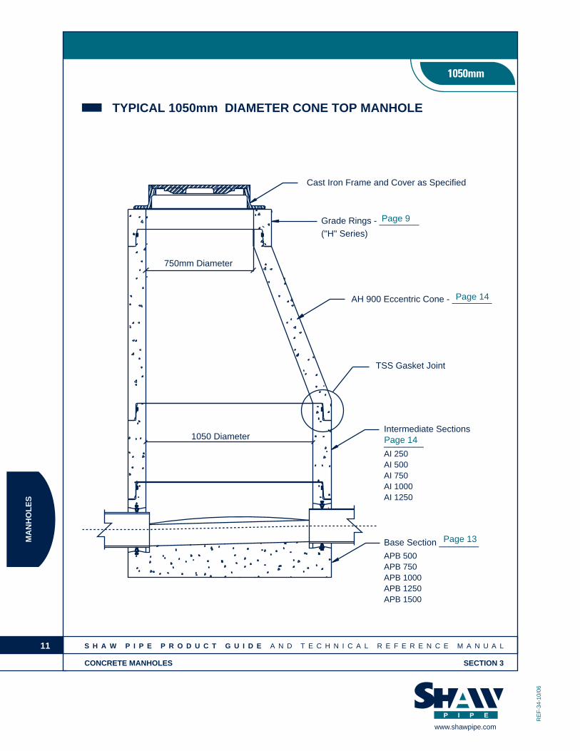
TYPICAL 1050mm DIAMETER CONE TOP MANHOLE
RE
F-3
4-10
/06
Cast Iron Frame and Cover as Specified
Grade Rings - ________("H" Series)
AH 900 Eccentric Cone - ________
TSS Gasket Joint
Intermediate Sections
________AI 250AI 500AI 750AI 1000AI 1250
Base Section ________
750mm Diameter
1050 Diameter
APB 500APB 750APB 1000APB 1250APB 1500
Page 9
Page 14
Page 14
Page 13

MA
NH
OL
ES
S H A W P I P E P R O D U C T G U I D E A N D T E C H N I C A L R E F E R E N C E M A N U A L
CONCRETE MANHOLES SECTION 3
www.shawpipe.com
1050mm
Typical Pre-Benched BaseWall and bottom cast as a single unit. Factory benching placed to suit size and location. Also availablewithout benching. Specify "Bottom Only".
Inside Diameter: 1067mmWall Thickness: 114mm
Maximum Pipe Size: c/w A-LOK gasket connection - 525mm concrete
* Laid Height estimate only. Dependant on pipe size and type.
Base Base Height *Laid Height WeightSection mm mm kg
APB 750 750 mm 640 mm 1270 kg
APB 1000 1000 mm 890 mm 1520 kg
APB 1250 1250 mm 1140 mm 1770 kg
APB 1500 1500 mm 1390 mm 2020 kg
12
RE
F-3
9-10
/06
MA
NH
OL
ES
S H A W P I P E P R O D U C T G U I D E A N D T E C H N I C A L R E F E R E N C E M A N U A L
CONCRETE MANHOLES SECTION 3
www.shawpipe.com
1050mm
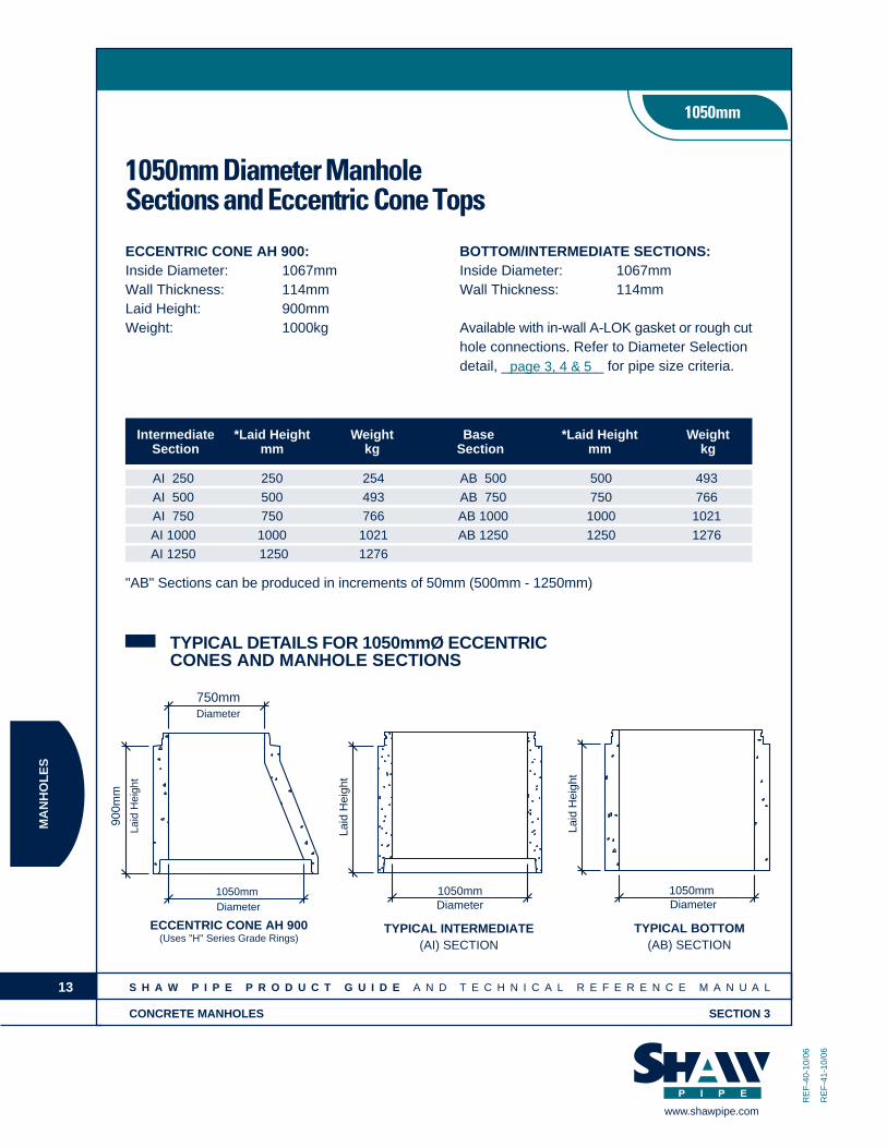
1050mm Diameter ManholeSections and Eccentric Cone Tops
ECCENTRIC CONE AH 900:Inside Diameter: 1067mmWall Thickness: 114mmLaid Height: 900mmWeight: 1000kg
BOTTOM/INTERMEDIATE SECTIONS:Inside Diameter: 1067mmWall Thickness: 114mm
Available with in-wall A-LOK gasket or rough cuthole connections. Refer to Diameter Selectiondetail, _____________ for pipe size criteria.
Intermediate *Laid Height Weight Base *Laid Height WeightSection mm kg Section mm kg
AI 250 250 254 AB 500 500 493
AI 500 500 493 AB 750 750 766
AI 750 750 766 AB 1000 1000 1021
AI 1000 1000 1021 AB 1250 1250 1276
AI 1250 1250 1276
"AB" Sections can be produced in increments of 50mm (500mm - 1250mm)
13
RE
F-4
0-10
/06
RE
F-4
1-10
/06
TYPICAL INTERMEDIATE(AI) SECTION
1050mmDiameter
Laid
Hei
ght
TYPICAL BOTTOM(AB) SECTION
1050mmDiameter
Laid
Hei
ght
ECCENTRIC CONE AH 900(Uses "H" Series Grade Rings)
750mmDiameter
1050mmDiameter
900m
m
Laid
Hei
ght
TYPICAL DETAILS FOR 1050mmØ ECCENTRICCONES AND MANHOLE SECTIONS
page 3, 4 & 5
MA
NH
OL
ES
S H A W P I P E P R O D U C T G U I D E A N D T E C H N I C A L R E F E R E N C E M A N U A L
CONCRETE MANHOLES SECTION 3
www.shawpipe.com
1050mm
14
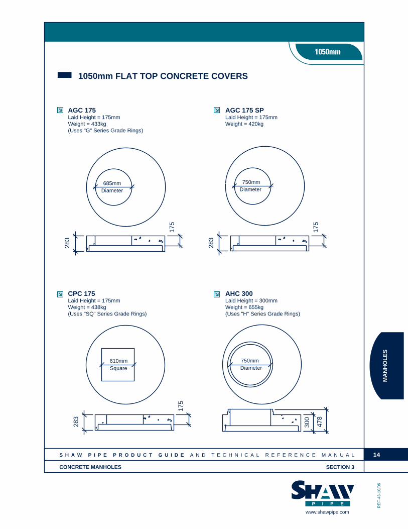
1050mm FLAT TOP CONCRETE COVERS
RE
F-4
3-10
/06
10
AGC 175Laid Height = 175mmWeight = 433kg(Uses "G" Series Grade Rings)
685mmDiameter
283
175
AHC 300Laid Height = 300mmWeight = 655kg(Uses "H" Series Grade Rings)
750mmDiameter
300
478
AGC 175 SPLaid Height = 175mmWeight = 420kg
175
283
Diameter750mm
CPC 175Laid Height = 175mmWeight = 438kg(Uses "SQ" Series Grade Rings)
Square610mm
283
175

MA
NH
OL
ES
S H A W P I P E P R O D U C T G U I D E A N D T E C H N I C A L R E F E R E N C E M A N U A L
CONCRETE MANHOLES SECTION 3
www.shawpipe.com
1200mm
RE
F-4
4-10
/06
15
TYPICAL 1200mm DIAMETER FLAT TOP MANHOLETYPICAL 1200mm DIAMETER FLAT TOP MANHOLE
Cast Iron Frame and Cover as Specified
Flat Top Cover - ________EGC 175EHC 300
Grade Rings - ________
Intermediate Sections
EI 500EI 750EI 1000EI 1250
Base Section - ________EPB 750EPB 1000EPB 1250
TSS Gasket Joint
___________
EPB 1500EPB 1750
EPB 2500EPB 2250EPB 2000
1200mm Diameter
Page 9
Page 19
Page 17 & 18
Page 16

MA
NH
OL
ES
S H A W P I P E P R O D U C T G U I D E A N D T E C H N I C A L R E F E R E N C E M A N U A L
CONCRETE MANHOLES SECTION 3
www.shawpipe.com
1200mm
Typical Pre-Benched BaseWall and bottom cast as a single unit. Factory benching placed to suit pipe size and location.
Also available without benching. Specify “Bottom Only”.
Inside Diameter: 1219mmWall Thickness: 127mm
Base Height *Laid Height WeightBase Section (mm) (mm) (kg)
EPB 750 740 mm 653 mm 1540 kg
EPB 1000 1000 mm 885 mm 1865 kg
EPB 1250 1250 mm 1140 mm 2190 kg
EPB 1500 1500 mm 1410 mm 3138 kg
EPB 1750 1750 mm 1660 mm 3514 kg
EPB 2000 2000 mm 1910 mm 3890 kg
EPB 2250 2250 mm 2160 mm 4266 kg
EPB 2500 2500 mm 2410 mm 4641 kg
16
RE
F-4
7-10
/06

MA
NH
OL
ES
S H A W P I P E P R O D U C T G U I D E A N D T E C H N I C A L R E F E R E N C E M A N U A L
CONCRETE MANHOLES SECTION 3
www.shawpipe.com
1200mm
TYPICAL DETAILS FOR 1200mmØ MANHOLESECTIONS AND TRANSITION CONE SECTIONS
TYPICAL INTERMEDIATE(EI) SECTION
TYPICAL BOTTOM(EB) SECTION
RE
F-4
8-10
/06
17
Laid
Hei
ght
1219mmDiameter
127mm
Diameter1219mm
Laid
Hei
ght 127mm

MA
NH
OL
ES
S H A W P I P E P R O D U C T G U I D E A N D T E C H N I C A L R E F E R E N C E M A N U A L
CONCRETE MANHOLES SECTION 3
www.shawpipe.com
1200mm
1200mm Diameter Manhole Sectionsand Transition Cones
BOTTOM/INTERMEDIATE SECTIONS:Inside Diameter: 1219mmWall Thickness: 127mm
Available with in-wall A-LOK gasket or rough cut inlet connections. Refer to Diameter SelectionDetail, page 26-28 for pipe size criteria.
Intermediate *Laid Height WeightSection (mm) (kg)
EI 500 500 645
EI 750 750 968
EI 1000 1000 1290
EI 1250 1250 1613
EI 2500 2500 3226
EB 500 500 645
EB 750 750 968
EB 1000 1000 1290
EB 1250 1250 1613
EB 2500 2500 3226
Base *Laid Height WeightSection (mm) (kg)
18
RE
F-4
9-10
/06

MA
NH
OL
ES
S H A W P I P E P R O D U C T G U I D E A N D T E C H N I C A L R E F E R E N C E M A N U A L
CONCRETE MANHOLES SECTION 3
www.shawpipe.com
1200mm
1200mm DIAMETER FLAT TOP COVERS
19
EGC 175Laid Height = 175mmWeight = 672kg(Uses "G" Series Grade Rings)
685mm
Diameter
175
293
EPC 175Laid Height = 175mmWeight = 672kg(Uses "SQ" Series Grade Rings)
Square
610mm
29317
5
EHC 300Laid Height = 300mmWeight = 920kg(Uses "H" Series Grade Rings)
300
478
750mm
Diameter
RE
F-5
1-10
/06

MA
NH
OL
ES
S H A W P I P E P R O D U C T G U I D E A N D T E C H N I C A L R E F E R E N C E M A N U A L
CONCRETE MANHOLES SECTION 3
www.shawpipe.com
1500mm-3000mm
TYPICAL 1500mm-3000mmDIAMETER FLAT TOP MANHOLELARGE DIAMETER MANHOLES
20
Grade Rings - _________
1500mm to 3000mm Dia.Base Section
_________
1500mm to 3000mm Dia.Flat Top Cover
_________
1500mm to 3000mm Dia.Intermediate Sections
_________
1500mm to 3000mm Dia.Intermediate Landing SectionsFor Deep Bury Manholes
_________
1500mm to 3000mm Dia.Intermediate Sections
_________
Cast Iron Frame and Cover as Specified
RE
F-5
4-12
/06
Page 9
Page 27
Page 26
Page 25
Page 26
Page 24

MA
NH
OL
ES
S H A W P I P E P R O D U C T G U I D E A N D T E C H N I C A L R E F E R E N C E M A N U A L
CONCRETE MANHOLES SECTION 3
www.shawpipe.com
1500mm-3000mm
TYPICAL 1500mm-3000mm DIAMETERTRANSITION MANHOLELARGE DIAMETER MANHOLES
21
Cast Iron Frame and Coveras Specified
Grade Rings - _________
Alternate AGC 175 Flat TopCover Arrangement
Intermediate Sections - _________AI 250AI 500AI 750AI 1000AI 1250
Reducing Section_________
1500mm to 3000mm Dia.Base Section_________
_________Intermediate Section1500mm to 3000mm Dia.
1050mm Dia.
Eccentric Cone - _________AH 900
RE
F-5
5-12
/06
Page 9
Page 14
Page 14
Page 25
Page 26
Page 24

MA
NH
OL
ES
S H A W P I P E P R O D U C T G U I D E A N D T E C H N I C A L R E F E R E N C E M A N U A L
CONCRETE MANHOLES SECTION 3
www.shawpipe.com
1500mm-3000mm
Walls and bottom cast as single unit. Factory benching placed to suit pipe size and location.(Some sizes may require bottom to be cast in a second pour). Base sections can be manufacturedin heights ranging from 500mm to 2550mm. Refer to Diameter Selection Detail, _____________for maximum pipe sizes.
TYPICAL PRE-BENCHED BASE
* Approximate weights based on bottom only bases(benching volume varies as per requirement, pipe size, etc).
** RPB 500 & QPB 500 Bases are "Mono" style and are fabricated c/w benching.*** 3000mm bases are fabricated with a separate base slab. See Lift Station section for detail.
22
ManholeSize
Diametermm
Wall Thickness(mm)
BaseSection
Base Height(mm)
Weight(kg)*
LPB 1000 1000 4268LPB 1250 1250 5018LPB 1500 1500 5768LPB 1750 1750 6518LPB 2000 2000 7268LPB 2250 2250 8018LPB 2500 2500 8768
1524 1711500mm
1800mm 1829 197
2100mm 2134 222
2400mm 2438 248
3000mm 3048 305
KPB 1000 1000 2395KPB 1250 1250 2766KPB 1500 1500 3139KPB 1750 1750 3511KPB 2000 2000 3883KPB 2250 2250 4255KPB 2500 2500 4627
RPB 500 500 4986RPB 1000 1000 5684RPB 1250 1250 6694RPB 1500 1500 7704RPB 1750 1750 8714RPB 2000 2000 9724RPB 2250 2250 10734RPB 2500 2500 11744
QPB 500 500 4941QPB 1000 1000 7246QPB 1250 1250 8497QPB 1500 1500 9794QPB 1750 1750 10456QPB 2000 2000 11481QPB 2250 2250 12506QPB 2550 2550 14737
TPB 300 300 7700TPB 1000 1000 7943TPB 1500 1500 11115TPB 2000 2000 14287TPB 2440 2440 17079
**
LARGE DIAMETER MANHOLES
RE
F-5
7-12
/06
Page 3, 4 & 5
**
***

MA
NH
OL
ES
S H A W P I P E P R O D U C T G U I D E A N D T E C H N I C A L R E F E R E N C E M A N U A L
CONCRETE MANHOLES SECTION 3
www.shawpipe.com
1500mm-3000mm
23
TYPICAL REDUCING SECTION
TYPICAL INTERMEDIATELANDING SECTION
TYPICAL INTERMEDIATESECTION
TYPICAL DETAILS FOR LARGE DIAMETERINTERMEDIATE AND REDUCING SECTIONS
685mm Diam.or as Specified
LaidHeight
Slab Thickness
1050mm DiameterSpigot
(203mm TYP.)
or as Specified685mm Diam.
Slab Thickness(203mm TYP.)
Inside Diameter (ID) Wall Thickness(WT)
LaidHeight
RE
F-5
8-12
/06

MA
NH
OL
ES
S H A W P I P E P R O D U C T G U I D E A N D T E C H N I C A L R E F E R E N C E M A N U A L
CONCRETE MANHOLES SECTION 3
www.shawpipe.com
1500mm-3000mm
Typical Intermediate SectionsLarge Diameter ManholesIntermediate sections are available with in-wall A-LOK gaskets or rough cut hole connections.Refer to the Manhole Diameter Selection detail, _____________, for the pipe size criteria.
Intermediate Laid Height WeightSection mm kg
KI 500 500 964KI 750 750 1445KI 1000 1000 1927KI 1250 1250 2409KI 1500 1500 2891KI 1750 1750 3373KI 2000 2000 3855KI 2250 2250 4337KI 2500 2500 4818
1500mm DIA. INTERMEDIATE SECTIONSInside Diameter: 1524mmWall Thickness: 152mm
Intermediate Laid Height WeightSection mm kg
LI 500 500 1348LI 750 750 2021LI 1000 1000 2695LI 1250 1250 3369LI 1500 1500 4043LI 1750 1750 4717LI 2000 2000 5391LI 2250 2250 6065LI 2500 2500 6738
1800mm DIA. INTERMEDIATE SECTIONSInside Diameter: 1829mmWall Thickness: 197mm
Intermediate Laid Height WeightSection mm kg
RI 750 750 2969RI 1000 1000 3959RI 1250 1250 4948RI 1500 1500 5938RI 1750 1750 6928RI 2000 2000 7918RI 2250 2250 8908RI 2500 2500 9896
2100mm DIA. INTERMEDIATE SECTIONSInside Diameter: 2134mmWall Thickness: 222mm
Intermediate Laid Height WeightSection mm kg
QI 750 750 3449QI 1000 1000 4599QI 1250 1250 5748QI 1500 1500 6898QI 1750 1750 8048QI 2000 2000 9198QI 2250 2250 10348QI 2440 2440 11726
2400mm DIA. INTERMEDIATE SECTIONSInside Diameter: 2438mmWall Thickness: 248mm
Intermediate Laid Height WeightSection mm kg
TI 750 750 6400TI 1000 1000 8500TI 1250 1250 10600TI 1500 1500 12800TI 1750 1750 14900TI 2000 2000 17100TI 2250 2250 19200TI 2440 2440 20500
3000mm DIA. INTERMEDIATE SECTIONSInside Diameter: 3048mmWall Thickness: 305mm
24
RE
F-5
9-12
/06
Page 3, 4 & 5

MA
NH
OL
ES
S H A W P I P E P R O D U C T G U I D E A N D T E C H N I C A L R E F E R E N C E M A N U A L
CONCRETE MANHOLES SECTION 3
www.shawpipe.com
1500mm-3000mm
LARGE DIAMETER FLAT TOP COVERSLARGE DIAMETER MANHOLES
25
RE
F-6
0-12
/06
(K,L,R,Q) PC 200TPC 300
610mmSquare
CoverThickness
(K,L,R,Q) GC 200TGC 300
CoverThickness
Diameter685mm
(K,L,R,Q,T)HC 300
760mmDiameter
CoverThickness

MA
NH
OL
ES
S H A W P I P E P R O D U C T G U I D E A N D T E C H N I C A L R E F E R E N C E M A N U A L
CONCRETE MANHOLES SECTION 3
www.shawpipe.com
1500mm-3000mm
Typical Flat Top CoversLarge Diameter ManholesFlat top covers are also available as intermediate landing or reducing sections. All covers producedwith the standard access opening as shown. Other configurations available upon request.
Flat Top Cover Thickness WeightCover mm kg
LGC 200 200 1860
LHC 250 250 2325
LPC 200 200 2900
Flat Top Cover Thickness WeightCover mm kg
QGC 200 200 3403
QHC 250 250 4254
QPC 200 200 5250
1800mm DIAMETER
2400mm DIAMETER
Flat Top Cover Thickness WeightCover mm kg
KGC 200 200 1314
KHC 250 250 1644
KPC 200 200 2000
Flat Top Cover Thickness WeightCover mm kg
RGC 200 200 2359
RHC 250 250 2949
RPC 200 200 3700
Flat Top Cover Thickness WeightCover mm kg
TGC 300 300 7700
THC 300 300 7600
TPC 300 300 7700
1500mm DIAMETER
2100mm DIAMETER
3000mm DIAMETER
26
RE
F-6
1-12
/06

MA
NH
OL
ES
S H A W P I P E P R O D U C T G U I D E A N D T E C H N I C A L R E F E R E N C E M A N U A L
CONCRETE MANHOLES SECTION 3
www.shawpipe.com
1500mm-3000mm
27
TYPICAL "TEE"-BASE MANHOLE
TYPICAL MANHOLE SECTION
180°TEE BASECONFIGURATION
Cast Iron Frame and Coveras Specified
Grade Rings
AH 900Eccentric Cone
ArrangementAlternate Flat Top Cover
TSS GasketBase Section
1050mm or1200mm Dia.IntermediateSections
RE
F-6
2-12
/06

MA
NH
OL
ES
S H A W P I P E P R O D U C T G U I D E A N D T E C H N I C A L R E F E R E N C E M A N U A L
CONCRETE MANHOLES SECTION 3
www.shawpipe.com
1500mm-3000mm
28
LONGITUDINAL SECTION
TRANSVERSE SECTION
TYPICAL "TEE" BASE DETAILS
Laid Length (Pipe)P
ipe
Dia
met
er
Laid
Hei
ght
(Man
hole
)
Directionof Flow
685mm Dia.Access Hole(or as specified)
Spigot for 1050mmor 1200mm Dia. Shafting
260mm
Laid
Hei
ght
Pip
e D
iam
eter
RE
F-6
3-12
/06

MA
NH
OL
ES
S H A W P I P E P R O D U C T G U I D E A N D T E C H N I C A L R E F E R E N C E M A N U A L
CONCRETE MANHOLES SECTION 3
www.shawpipe.com
1500mm-3000mm
Typical 'Tee'-Base Section‘Tee’-Base sections are normally used to provide access to large diameter pipe lines. Generally, slopesare minimal and they have only an inlet and outlet of the same size although smaller inlets may beincorporated in the structure.
They are available in sizes ranging from 600mm to 2400mm diameter concrete pipe. Spigots for 1050mmor 1200mm diameter shafting are cast integral with the base section.
Due to the diverse applications in which they may be utilized, please contact SHAW PIPE for specificinformation pertaining to your project.
‘Tee’-Base Laid HeightPipe Diameter (mm) (mm)
600 965
750 1130
900 1315
1050 1460
1200 1625
1500 1955
1800 2305
2100 2635
2400 2965
Weights of ‘Tee’-Base Units are available on request.
29
RE
F-6
4-12
/06

MA
NH
OL
ES
S H A W P I P E P R O D U C T G U I D E A N D T E C H N I C A L R E F E R E N C E M A N U A L
CONCRETE MANHOLES SECTION 3
www.shawpipe.com
1500mm-3000mm
STANDARD MANHOLE DETAILS
1050-3000mmØ - TYPICAL INTERNAL DROP MANHOLE
Cast Iron Frame and Cover as Specified
Grade Rings - ________
Flat Top Cover - ________
Intermediate Drop
Top Section - ________
Intermediate Drop
Top Section - ________
Base Section - ________
DropChannel
30
RE
F-5
2-12
/06
Page 9
Page 27
Page 26
Page 21
Page 24

MA
NH
OL
ES
S H A W P I P E P R O D U C T G U I D E A N D T E C H N I C A L R E F E R E N C E M A N U A L
CONCRETE MANHOLES SECTION 3
www.shawpipe.com
1500mm-3000mm
31
TYPICAL PLAN
TYPICAL INTERMEDIATEINTERNAL DROP TOP SECTION
TYPICAL INTERMEDIATEINTERNAL DROP SECTION
1050-3000mm DIAMETER DROP MANHOLE SECTION DETAILSSTANDARD DROP MANHOLE
375mmDiameter
Inlet Opening
Drop Channel(Standard Size Shown)
RE
F-5
3-12
/06
Inlet Opening
51mm
150m
m M
in.
Diameter to Suit Varies
Laid
Hei
ght
375mm
Drop Channel(Standard Size Shown)
Diameter
VariesDiameter to Suit
Laid
Hei
ght
51mm
(Standard Size Shown)Drop Channel
375mmDiameter