concrete journal, vol.48, no.7, jul. 2010
TRANSCRIPT

Title Authors
Commentaries/
Possibility of Retrofit of Existing Reinforced ConcreteBuildings with Low Strength Concrete
Technical reports/
Investigation of Actual Conditions concerning ConcreteDrying Shrinkage in All over the Country
Construction records/
Design and Construction of Large Caliber Caisson Type Pilefor Uratakao Bridge
Construction records/
Application of the LRV Construction Methodto a Super High-rise Apartment House
Ken KAWAI, Takashi SHINODA,Kumiko SUDA and YoshimitsuWATANABE
Shigetoshi OYAMA, KoheiKURITA, Yuichi IKEDA andNaoto FUJIU
Concrete Journal, Vol.48, No.7, Jul. 2010
Hideo ARAKI, MomoyoNEGUCHI and Koichi MINAMI
Kazuo SUZUKI, KazushiTSUJIMOTO, Takeaki KANAIand Yasuhide SOEDA
Concrete Journal Vol.48, No.7, pp.3-8, Jul., 2010/ Copyright ○c Japan Concrete Institute
(email:[email protected])
Keywords: low strength concrete, seismic evaluation, seismic retrofit, existing reinforced concrete buildings
1. Background Seismic evaluations of existing RC buildings have been extensive in Japan since the 1995 Kobe earthquake. According to some reports, seismic evaluations found many RC buildings to have very low concrete strength, i.e. less than half of the design concrete strength. It was reported that in many samples of low strength concrete, less than 10MPa was found in concrete cylinders obtained from existing buildings constructed during the 1960s and 1970s, although a design strength of 18MPawas usually used in Japan at that time.
At present, even when the concrete strength of the existing buildings is lower than that limit strength, seismic evaluations and retrofitting are performed. Although those buildings that have serious problems are intended to be used continuously, we still do not have any fundamental knowledge of low strength concrete. With this background, the authors formed a committee in the Chugoku branch of the Japan Concrete Institute to discuss low strength concrete. In this commentary, details of the committee’s reports and further research are described. 2. Mechanical Properties of Low Strength Concrete
According to previous studies, concrete with strengths greater than 9MPa and less than 13.5MPa --13.5MPa is the recommended lower limit of concrete strength according to the Standard for Seismic Evaluation of Existing Reinforced Concrete Building-- is hereafter defined as LSC --LSC is the low strength concrete--. When we apply the experimental results of LSC to those buildings, it is necessary to clarify the differences in the mechanical characteristics between the concrete obtained from the existing buildings and concrete manufactured in the laboratory. In stress-strain curves LSC shows very ductile behavior. The compressive stress gradually decreases after the maximum strength while compressive strains increase to more than 20,000µ. The modulus of elasticity of the existing building was lower than
that observed in the laboratory. 3. Strength of RC members
The main purpose of previous studies on LSC members was to investigate the shear strength of the columns, which was an important factor in the seismic evaluation. Yamamoto proposed a reduction factor for the empirical shear strength equation. The theoretical ultimate strength based on the truss and the arch mechanism was also proposed. In the series of experimental studies concerning LSC members, it was pointed out for the first time that the flexural strength of members with plain round bars was much lower than the calculated values, assuming yielding of main bars. This result is due to the occurrence of bond slip failure before yielding. Considering bond strength, an equation is proposed to obtain strength of members with plain round bars in LSC. 4. Retrofitting for Members and Frames
The retrofitting methods of LSC columns were usually carbon fiber reinforced plastics (CFRP) and steel wrapping, in the same way as normal RC columns. Ductility was significantly improved by this retrofit, although the increase in strength was not expected. The quantitative evaluation of ductility is desired in the seismic evaluation, because the carrying capacity of LSC building is basically insufficient, and the designer can enhance lateral resistance using the new resisting members. Careful consideration of the joint between the existing frame and the newly constructed member is required when concrete strength is low. In particular, punching failure is anticipated at the corner joint when resisting members are set into the frame. 5. Conclusion
From experimental results, it is indicated that there is the possibility of retrofit of low strength concrete buildings. In further research, full scale tests using members of the existing building will be indispensable in verifying the proposed retrofitting procedure.
Commentaries
Possibility of Retrofit of Existing Reinforced Concrete Buildings
with Low Strength Concrete Hideo ARAKI*1, Momoyo NEGUCHI*2 and Koichi MINAMI*3
*1 Associate Professor, Graduate School of Engineering, Hiroshima University, Dr. E., JCI Member *2 Minami Laboratory, Faculty of Engineering, Fukuyama University, M. E., JCI Member *3 Professor, Faculty of Engineering, Fukuyama University, Dr. E., JCI Member
Concrete Journal Vol.48, No.7, pp.9-14, Jul., 2010/ Copyright ○c Japan Concrete Institute
Keywords: Drying shrinkage rate, Quality of Aggregate, Mixture proportions
Research on the actual condition
A concrete drying shrinkage rate was prescribed for Architectural Standard Specification for Reinforced Concrete Work (JASS5)-2009 of the AIJ (Architectural Institute of Japan) and the standard specification for concrete structures-2007 of the JSCE (Japan Society of Civil Engineers). But, a drying shrinkage rate isn't prescribed for 5308:2009 (Ready-Mixed concrete) as the quality requirement items.
Because of that, the countermeasure to decrease drying shrinkages wasn't examined in the ready-mixed concrete factory with no shipping experience the construction work of the large metropolitan area in many cases. And, it may not be understood by the factory that it is the quality of the concrete which a purchaser demands.
As one of the guarantee measures concerning the drying shrinkage rate against the purchaser, National Federation ready-mixed concrete industrial association did investigation of actual
conditions of the ready-mixed concrete factory in 2008 and 2009 years. In the investigation, information on material quality, mixture proportions, and hardened concrete quality was collected as a basic intelligence needed to examine a dry shrinkage measures.
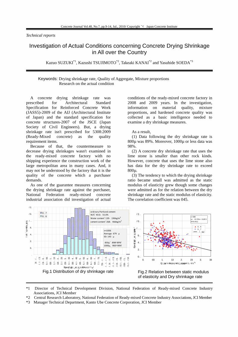
As a result, (1) Data following the dry shrinkage rate is
800µ was 89%. Moreover, 1000µ or less data was 98%.
(2) A concrete dry shrinkage rate that uses the lime stone is smaller than other rock kinds. However, concrete that uses the lime stone also has data for the dry shrinkage rate to exceed 800µ.
(3) The tendency to which the drying shrinkage ratio became small was admitted as the static modulus of elasticity grew though some changes were admitted as for the relation between the dry shrinkage rate and the static modulus of elasticity. The correlation coefficient was 045.
Technical reports
Investigation of Actual Conditions concerning Concrete Drying Shrinkage in All over the Country
Kazuo SUZUKI*1, Kazushi TSUJIMOTO*2, Takeaki KANAI*2 and Yasuhide SOEDA*3
*1 Director of Technical Development Division, National Federation of Ready-mixed Concrete IndustryAssociations, JCI Member
*2 Central Research Laboratory, National Federation of Ready-mixed Concrete Industry Associations, JCI Member*3 Manager Technical Department, Kanto Ube Concrete Corporation, JCI Member
Fig.1 Distribution of dry shrinkage rate
0
20
40
60
80
100
120
140
51~100
101~150
151~200
201~250
251~300
301~350
351~400
401~450
451~500
501~550
551~600
601~650
651~700
701~750
751~800
801~850
851~900
901~950
951~1000
1001~1050
1051~1100
1101~1150
1151~1200
1201~1250
1251~1300
1301~1350
Dry shrinkage rate(26week)(μ)
number of cases
2009
2008
n=1006Average: 679 μSD: 143 μ
850μ>898(89%)1000μ≧983(98%)
ordinary Portland cementW/C:40.0~55.0%
Water content:139~196kg/m3
cement content:268~466kg/m3
Fig.2 Relation between static modulus of elasticity and Dry shrinkage rate
200
400
600
800
1000
1200
1400
20 25 30 35 40 45 50 55
Static modulus of elasticity(kN/mm2)
Dly shrinkage ratio(μ) 2008
2009
線形 (all)
n=398y=-13.722x + 1120.5(R=0.451)

Concrete Journal Vol.48, No.7, pp.16-21, July, 2010/ Copyright ○c Japan Concrete Institute
Keywords: large caliber caisson type pile, SD490, SD390, grout filled mechanical re-bar connector, high-altitude working vehicle, shortening of the period of construction
Large caliber caisson type pile was adopted on Uratakao bridge with the aim of rationalization of design and construction by using some materials and machines such as high-strength re-bar (SD490, SD390), high-altitude working vehicles for re-bar assembly and grout filled mechanical re-bar connector. That enabled to shorten the period of construction.
In this report, outline of the design and construction of six large caliber caisson type piles for the bridge is described.
Construction records
Design and Construction of Large Caliber Caisson Type Pile for Uratakao Bridge
Ken KAWAI*1, Takashi SHINODA*2 , Kumiko SUDA*3 and Yoshimitsu WATANABE*4
*1 Hachiouji Construction Office, Tokyo branch, Central Nippon Expressway Company Limited *2 Hachiouji Construction Office, Tokyo branch, Central Nippon Expressway Company Limited *3 Tokyo Civil Engineering Branch, Kajima Corporation, JCI member *4 Tokyo Civil Engineering Branch, Kajima Corporation
Photo.2 Construction of large caliber caisson type pile
Photo.1 Construction of Uratakao Bridge
Concrete Journal Vol.48, No.7, pp.22-27, Jul., 2010/ Copyright ○c Japan Concrete Institute
Keywords: precast concrete, super high-rise apartment house, survey, tower crane
1. Introduction
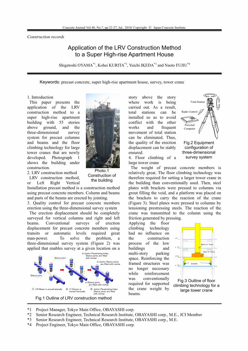
This paper presents the application of the LRV construction method to a super high-rise apartment building with 55 stories above ground, and the three-dimensional survey system for precast columns and beams and the floor climbing technology for large tower cranes that are newly developed. Photograph 1 shows the building under construction. 2. LRV construction method
LRV construction method, or Left Right Vertical Installation precast method is a construction method using precast concrete members. Column and beams and parts of the beams are erected by jointing. 3. Quality control for precast concrete members erection using the three-dimensional survey system
The erection displacement should be completely surveyed for vertical columns and right and left beams. Conventional surveys of erection displacement for precast concrete members using transits or automatic levels required great man-power. To solve the problem, a three-dimensional survey system (Figure 2) was applied that enables survey at a given location on a
story above the story where work is being carried out. As a result, total stations can be installed so as to avoid conflict with the other works and frequent movement of total station can be eliminated. Thus, the quality of the erection displacement can be stably ensured. 4. Floor climbing of a large tower crane
The weight of precast concrete members is relatively great. The floor climbing technology was therefore required for setting a larger tower crane in the building than conventionally used. Then, steel plates with brackets were pressed to columns via grout filling the void, and a platform was placed on the brackets to carry the reaction of the crane (Figure 3). Steel plates were pressed to columns by tensioning prestressing steels. The reaction of the crane was transmitted to the column using the friction generated by pressing. Applying the floor climbing technology had no influence on the construction process of the low buildings and multi-story parking space. Reinforcing the framed structures was no longer necessary while reinforcement was conventionally required for supported the crane weight by beams.
Construction records
Application of the LRV Construction Method to a Super High-rise Apartment House
Shigetoshi OYAMA*1, Kohei KURITA*2, Yuichi IKEDA*3 and Naoto FUJIU*4
*1 Project Manager, Tokyo Main Office, OBAYASHI corp. *2 Senior Research Engineer, Technical Research Institute, OBAYASHI corp., M.E., JCI Member *3 Senior Research Engineer, Technical Research Institute, OBAYASHI corp., M.E. *4 Project Engineer, Tokyo Main Office, OBAYASHI corp.
Photo.1 Construction of
the building
Sleeve joint
Sleeve joint
b)Joints・Sleeve joints are filled with mortar
a)Sleeve joints are filled with mortar
b)Joints・Penetrating holes Sleeve joints are filled
with mortar
② V-Column is moved Vertically
① LR-Beam is moved laterally ③ Joints・Penetrating holes Sleeve joints are filled
with mortar
Fig.1 Outline of LRV construction method
PersonalComputer
Total Station
Radio Control
Fig.2 Equipment configuration of
three-dimensional survey system
bracket
n F
Base of Crane
Masts of Crane
n - 1 F
n-2 F
n - 3 F
Fig.3 Outline of floor climbing technology for a
large tower crane