conceptual site models for ordnance and explosives … · hazardous, toxic, and radioactive waste...
TRANSCRIPT
EM 1110-1-1200 3 February 2003
CONCEPTUAL SITE MODELS FOR ORDNANCE AND EXPLOSIVES (OE) AND HAZARDOUS, TOXIC, AND RADIOACTIVE WASTE (HTRW) PROJECTS ENGINEER MANUAL
“Approved for public release; distribution is unlimited.”

DEPARTMENT OF THE ARMY EM 1110-1-1200 U.S. Army Corps of Engineers CECW-ET Washington, DC 20314-1000 Manual No. 1110-1-1200 3 February 2003
Engineering and Design CONCEPTUAL SITE MODELS FOR ORDNANCE AND EXPLOSIVES (OE) AND
HAZARDOUS, TOXIC, AND RADIOACTIVE WASTE (HTRW) PROJECTS 1. Purpose. This Engineer Manual (EM) provides U.S. Army Corps of Engineers (USACE) and other personnel with procedural guidance to develop Conceptual Site Models (CSMs) at sites potentially containing ordnance and explosives (OE) and/or hazardous, toxic, and radioac-tive waste (HTRW) environmental contamination. The CSM is a description of a site and its en-vironment that is based on existing knowledge. It describes sources and receptors, and the inter-actions that link these. It assists the team in planning, interpreting data, and communicating. The CSM will provide a planning tool to integrate information from a variety of resources, to evalu-ate the information with respect to project objectives and data needs, and to respond through an iterative process for further data collection or action. The target audience is the project delivery team (PDT). 2. Applicability. This manual applies to all Headquarters, U.S. Army Corps of Engineers (HQUSACE) elements, USACE Major Subordinate Commands, USACE geographic districts, and field operating activities having responsibilities for civil works and/or military programs with OE and HTRW-related issues. This guidance is provided to assist any organization or PDT involved in evaluation and decision-making. The CSM development process in this manual is applicable to any phase of a project, including investigation, design, response, and operation and maintenance of remedial systems with recurring review. 3. Distribution Statement. Approved for public release; distribution is unlimited. 4. References. Related bibliographic materials are at Appendix A. ER 5-1-11 U. S. Army Corps of Engineers Business Process ER 1110-1-263 Chemical Data Quality Management for Hazardous Waste Remedial Activities EM 200-1-2 Technical Project Planning Process EP 1110-1-18 Ordnance and Explosives Response

DEPARTMENT OF THE ARMY EM 1110-1-1200 U.S. Army Corps of Engineers CECW-ET Washington, DC 20314-1000 Manual No. 1110-1-1200 3 February 2003
Engineering and Design CONCEPTUAL SITE MODELS FOR ORDNANCE AND EXPLOSIVES (OE) AND
HAZARDOUS, TOXIC, AND RADIOACTIVE WASTE (HTRW) PROJECTS
Table of Contents Subject Paragraph Page Chapter 1 Introduction Purpose ............................................................................................. 1-1 1-1 Scope ................................................................................................ 1-2 1-2 Chapter 2 Description of a Conceptual Site Model Introduction ....................................................................................... 2-1 2-1 Conceptual Site Model Defined ........................................................ 2-2 2-1 Team Composition ............................................................................ 2-3 2-2 Profiles Needed to Develop a CSM .................................................. 2-4 2-2 Pathway Analysis .............................................................................. 2-5 2-4 Representation of the CSM ............................................................... 2-6 2-4 Iterative Development of the CSM ................................................... 2-7 2-8 Chapter 3 Development of a Conceptual Site Model for OE Projects Introduction ....................................................................................... 3-1 3-1 Profile Information Resources .......................................................... 3-2 3-1 Facility Profiles ................................................................................. 3-3 3-1 Physical Profiles................................................................................ 3-4 3-4 Release Profiles ................................................................................. 3-5 3-6 Land Use and Exposure Profiles ....................................................... 3-6 3-6 Ecological Profiles ............................................................................ 3-7 3-6 Pathway Analysis .............................................................................. 3-8 3-6

EM 1110-1-1200 3 Feb 03
Subject Paragraph Page Chapter 4 Development of a Conceptual Site Model for HTRW Projects Introduction ....................................................................................... 4-1 4-1 Profile Information Resources .......................................................... 4-2 4-1 Facility Profiles ................................................................................. 4-3 4-1 Physical Profiles................................................................................ 4-4 4-2 Release Profiles ................................................................................. 4-5 4-2 Land Use and Exposure Profiles ....................................................... 4-6 4-3 Ecological Profiles ............................................................................ 4-7 4-3 Pathway Analysis .............................................................................. 4-8 4-3 Chapter 5 Development of an Integrated Conceptual Site Model for OE and HTRW Projects Introduction ....................................................................................... 5-1 5-1 Profile Information Resources .......................................................... 5-2 5-1 Facility Profiles ................................................................................. 5-3 5-1 Physical Profiles................................................................................ 5-4 5-3 Release Profiles ................................................................................. 5-5 5-4 Land Use and Exposure Profiles ....................................................... 5-6 5-4 Ecological Profiles ............................................................................ 5-7 5-4 Pathway Analysis .............................................................................. 5-8 5-4 Appendix A Bibliography Appendix B Acronyms and Definitions Appendix C Range Operations Overview Appendix D Development of an Integrated CSM
ii

EM 1110-1-1200 3 Feb 03
Chapter 1 Introduction 1-1. Purpose
a. This Engineer Manual (EM) provides U.S. Army Corps of Engineers (USACE) and other personnel with procedural guidance to develop Conceptual Site Models (CSMs) at sites poten-tially containing ordnance and explosives (OE) or hazardous, toxic, and radioactive waste (HTRW), or both. The CSM is an integral part of the Technical Project Planning (TPP) process. The target audience is the Project Delivery Team (hereinafter referred to as the team).
Pursuant to the Corps’ Project Management Business Process, the District Project Manager is the leader of the project delivery team (PDT) who must seamlessly integrate USACE efforts to deliver the best possible solution for the customer. The OE and HTRW team members must coordinate with each other to ensure that data collection is complementary and meets project objectives.
b. A primary objective of this guide is to bring synergy to the OE and environmental projects at a site. There are numerous closing and formerly used military sites in this country that have both OE and HTRW issues. These issues have typically been addressed as separate program categories within USACE, with one focusing exclusively on OE and another on HTRW. A common goal for each program category, however, is to achieve site closeout in a safe, environ-mentally responsible, and cost-effective manner. It is critical to coordinate efforts to obtain this goal of site closeout. The USACE District Project Manager (PM) must ensure that site data col-lection supports both program categories and is utilized efficiently. Sites are commonly ad-dressed sequentially, beginning with OE before focusing on HTRW. Rarely are both imple-mented at the same time, often as a result of differing safety priorities or budgets. However, knowing the distribution of OE at a site and any re-corded observations of spills, stains, or buried waste can be a critical first layer of data to build a CSM for an HTRW project. Development of an OE CSM should assist the team in designing the environmental data collection and response actions, resulting in more efficient use of resources and faster closeout at sites. Additional benefits include better understand-ing and appreciation of the coordinated process re-quired by regulatory personnel and other stake-holders.
c. This guidance should be used together with other USACE guidance for project execution. Development of a CSM is an integral component of planning and data collection activities de-scribed in the USACE TPP Process (EM 200-1-2). The TPP process provides a framework for identifying project objectives to achieve site closeout, determining data needs to meet those ob-jectives, evaluating the options for data collection, and finalizing the data collection program for optimum results. It also fulfills the requirements of the systematic planning process endorsed by the U.S. Environmental Protection Agency (USEPA). The TPP process allows for development of Data Quality Objectives (DQOs) through a step-wise series of problem identification, analy-sis, and response. It encourages the team to determine data gaps, to ensure data collected are ap-
1-1
EM 1110-1-1200 3 Feb 03
propriate for the project objectives, and to consider the end use of data before they are collected. This process results in more efficient and cost-effective investigation, cleanup, and monitoring.
d. This manual is also consistent with USACE Engineer Regulation (ER) 5-1-11, U.S. Army
Corps of Engineers Business Process; ER 1110-1-263, Chemical Data Quality Management for Hazardous Waste Remedial Activities; and EP 1110-1-18, Ordnance and Explosives Response. Users are required to review these other guidance documents to determine the applicable inte-gration of CSM guidance. 1-2. Scope The CSM development process in this manual is applicable to any phase of an OE or HTRW project. These include investigation, design, response phases, and during operation/maintenance of remedial systems with recurring review. The CSM is not a separate deliverable, but a compo-nent of existing documents such as work plans, sampling and analysis plans, site characterization reports, final removal reports, or similar documents as determined by the team. This process may be applied under any regulatory framework.
1- 2


EM 1110-1-1200 3 Feb 03
team. The team integrates this information to illustrate relationships between the potential sources and receptors that may be affected. Through this illustration, the team conducts a path-way analysis to show how site conditions, including the exposure pathways, function as a sys-tem. As more data are generated, the understanding of this system becomes more refined. This understanding allows greater focus for subsequent investigations or for design and response ac-tivities. 2-3. Team Composition
Team composition will vary with the complexity of the site and the nature of the OE hazards or HTRW contami-nants present. The PM leads a team that consists of tech-nical experts, regulatory personnel, and other stake-holders. An effort should be made early in the process to identify special challenges or interests that require input from specific disciplines or groups. These personnel rep-resent various planning perspectives, including decision-makers, data users, and data implementers, as described in the TPP Process manual (EM-200-1-2). Each group will hmay contain differences and overlaps. One aspect of develophaving both OE and HTRW is the importance of early and ocal experts on the team. 2-4. Profiles Needed to Develop a CSM An effective CSM presents known or suspected conditions aand the interactions between them. The team must be able totion relevant to developing the CSM. In most cases, the needinto five “profile types” that address specific yet overlappingtypes include: • Facility Profile—describes man-made features and poten• Physical Profile—describes factors that may affect releas• Release Profile—describes the movement and extent of c• Land Use and Exposure Profile—provides information u
applicable exposure scenarios, receptors, and receptor lo• Ecological Profile—describes the natural habitats of the
areas.
2- 2
Profile information may be collected from a variety of resources. The team should review all relevant historical and current documentation, conduct interviews, and per-form a site visit, as needed, to gather profile informa-
“The Project Delivery Team (PDT) will include the customer(s), the PM, technical experts within or outside the local USACE activity, specialists, consultants/contractors, stakeholders, representatives from other state or federal agencies, and vertical members from division and headquarters that arenecessary to effectively develop and deliver the project.” U.S. Army Corps of Engineers (ER 5-1-11)
ave a set of data needs, and these ing a CSM for a site potentially ngoing coordination between techni-
bout sources and potential receptors, recognize those types of informa-ed information may be categorized types of information. These profile
tial sources at or near the site. e, fate and transport, and access. ontaminants in the environment. sed to identify and evaluate the cations. site and ecological receptors in those
Early involvement of team members and identification of project goals and objectives (culminating in site closeout) are important during the CSM development process.

EM 1110-1-1200 3 Feb 03
tion. Typical information associated with each profile type is presented in Table 2-1. These in-formation needs are not comprehensive, and each site may require different or additional information as determined by the team.
Table 2-1. Profile Types and Information Needs
Profile Type Typical Information Needs Facility Profile • All structures, sewer systems, process lines, underground utilities
• Physical boundaries (past and current), fencing, administrative controls, etc. • Current and historical process and manufacturing areas • Ordnance activity areas (firing points, impact areas, storage areas, munitions
manufacturing, or disposal areas) • Storage and waste disposal • Historical features that indicate potential source areas (landfills or lagoons, ground
scars, impact craters) Physical Profile
• Topographic and vegetative features or other natural barriers • Surface water features and drainage pathways • Surface and subsurface geology, including soil type and properties • Meteorological data • Geophysical data • Hydrogeological data for depth to ground water and aquifer characteristics • Other physical site factors that affect site activities • Soil boring or monitoring well logs and locations
Release Profile
• Determination of contaminant movement from source areas • Contaminants and media of potential concern • Impact of chemical mixtures and co-located waste on transport mechanisms • Locations and delineation of confirmed releases with sampling locations • Migration routes and mechanisms (HTRW and OE constituents) • Modeling results
Land Use and Exposure Profile
• Receptors associated with current and reasonable future land use on and near the facility (residential, recreational, commercial, agricultural, industrial, public forest, etc.)
• Zoning • Types of current or future activities at the facility, including frequency and nature of
activity (intrusive or non-intrusive) • Beneficial resource determination (aquifer classification, natural resources,
wetlands, cultural resources, etc.) • Resource use locations (water supply wells, recreational swimming, boating, or
fishing areas, hiking trails, grazing lands, historical burial grounds, etc.) • Demographics, including subpopulation types and locations (schools, hospitals, day
care centers, site workers, etc.) Ecological Profile
• Description of the property at the facility, including habitat type (wetland, forest, desert, pond, etc.)
• Primary use of the property and degree of disturbance, if any • Identification of any ecological receptors in relation to habitat type (endangered or
threatened species, migratory animals, fish, etc.) • Relationship of any releases to potential habitat areas (locations, contaminants or
hazards of concern, sampling data, migration pathways, etc.)
2-3

EM 1110-1-1200 3 Feb 03
2-5. Pathway Analysis
The team uses information from the profiles to identify all actual, potentially complete, or incom-plete source–receptor interactions for the site, for both culand use. An exposure pathway is the course a chemical oa receptor. For OE projects, each pathway must include aEach pathway for an HTRW project must include a sourcroute, and a receptor. An HTRW pathway may also incluzation) and a transport medium (e.g., air), if the point of the source. The CSM will illustrate all complete ex-posure pathways, current and future. The pathway analysis, represented by the CSM, will guide data collection activities and can be used to inform stake-holders of site conditions.
a. Source. Sources are those areas where OE or HTRW has entered (or may enter) the physical system. Iis collected when the Facility, Physical, and Release Profsource may be easily labeled, such as an impact range orthe entire team completely understand as much about themunitions or contaminants. Early in the project, many ofknown. It is necessary for the team to determine what is source.
b. Interaction. Interaction describes ways that receptformation from all profiles will assist in identifying sourcmovement of OE is not significant, and interaction will oaccess and activity. However, there can be some movemfrost heave, tidal action, and erosion, or from human actiundergo various processes (e.g., volatilization, migrationarea can become contaminated. Therefore, the team mustmedia (exposure media) as well as all exposure routes (inin evaluating the source–receptor interactions at HTRW
c. Receptors. A receptor is an organism (human or ecphysical agent. The pathway evaluation must consider bofuture land use, as receptors are determined on that basisceptors are identified in the Land Use and Exposure, andsubcategories can include residents, site workers, construtrespassers.
2- 4
Source–receptor interaction for an OE CSM requires two components: Accessand Activity.
rrent and reasonably anticipated future r physical agent takes from a source to source, access, activity, and a receptor. e, an exposure medium, an exposure de a release mechanism (e.g., volatili-exposure is not at the same location as
Source–receptor interaction for an HTRW CSM requires two components: an Exposure Medium and an Exposure Route. A release mechanism and transport medium may also be present.
nformation on sources and source areas iles are generated. Even though a
a landfill, it is extremely important that source as possible, including probable the details of the source may not be known and what is assumed about the
ors come into contact with a source. In-e–receptor interactions. Typically, ccur only at the source area, limited by ent through natural processes, such as vity. Environmental contaminants often ) such that media other than the source consider all potentially contaminated gestion, inhalation, and dermal contact)
sites.
ological) that contacts a chemical or th current and reasonably anticipated
. Appropriate human and ecological re- Ecological Profiles. Human receptor ction workers, recreational users, and
EM 1110-1-1200 3 Feb 03
2-6. Representation of the CSM
The CSM will illustrate the sources and receptors present at the site, and the interactions that may result in exposure. For OE projects, the CSM will aid in determining whether hazards from OE are present. Similarly, for HTRW projects, the CSM will help determine whether risk from chemical contamination exists.
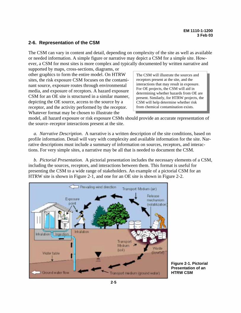
The CSM can vary in content and detail, depending on complexity of the site as well as available or needed information. A simple figure or narrative may depict a CSM for a simple site. How-ever, a CSM for most sites is more complex and typically documented by written narrative and supported by maps, cross-sections, diagrams, or other graphics to form the entire model. On HTRW sites, the risk exposure CSM focuses on the contami-nant source, exposure routes through environmental media, and exposure of receptors. A hazard exposure CSM for an OE site is structured in a similar manner, depicting the OE source, access to the source by a receptor, and the activity performed by the receptor. Whatever format may be chosen to illustrate the model, all hazard exposure or risk exposure CSMs should provide an accurate representation of the source–receptor interactions present at the site.
a. Narrative Description. A narrative is a written description of the site conditions, based on
profile information. Detail will vary with complexity and available information for the site. Nar-rative descriptions must include a summary of information on sources, receptors, and interac-tions. For very simple sites, a narrative may be all that is needed to document the CSM.
b. Pictorial Presentation. A pictorial presentation includes the necessary elements of a CSM, including the sources, receptors, and interactions between them. This format is useful for presenting the CSM to a wide range of stakeholders. An example of a pictorial CSM for an HTRW site is shown in Figure 2-1, and one for an OE site is shown in Figure 2-2.
Figure 2-1. Pictorial Presentation of an HTRW CSM
2-5

EM 1110-1-1200 3 Feb 03
OE Source
Activity Resulting in Exposure
Receptor with Access to Site
Figure 2-2. Pictorial Presentation of an OE CSM
c. Graphical Presentation. The graphical presentation provides a concise summary of com-
plete or incomplete exposure pathways. It is commonly used for HTRW projects and may also be used for OE projects. However, the potential interactions between the source and receptors are assessed differently, as described below.
(1) A graphical presentation of a CSM for an HTRW project is shown in Figure 2-3. This example focuses on a single contamination source in soil. Secondary sources or secondary path-ways may also be identified, and can be represented by the addition of these components to the diagram. Interaction between the source and receptors involves a release mechanism for the contaminant, an exposure medium that contains the contaminant, and an exposure route that places the receptor into contact with the contaminated medium. Additional pathways can be added to the model as necessary. For example, for sites with a radioactive source area, an expo-sure pathway could be added for external radiation for both the soil pathway and the inhalation pathway.
(2) A graphical presentation of a CSM for an OE project is shown in Figure 2-4. This ex-
ample focuses on an impact area as the OE source. Interaction between the potential receptors and an OE source has two components. The receptor must have access to the source and must engage in some activity that results in contact with individual OE items within the source area.
2- 6

EM 1110-1-1200 3 Feb 03
EMPLOYEE
CURRENTUSE
EMPLOYEE
FUTURE USE
RESIDENTExposure
RouteExposureMedium
ContaminationRelease
MechanismContamination
TCE inSoil
COMPLETE PATHWAYINCOMPLETE PATHWAY
Leaching
GRAPHIC HTRW CSM
Fugitive Dust
Volatilization
Soil
Air
Groundwater Ingestion
Vapor Inhalation
Dermal Contact
Inhalation
Ingestion
Dermal Contact
EXPOSURE PATHWAYS FOR HUMAN RECEPTORS
SOURCE INTERACTION RECEPTORS
Figure 2-3. Graphic Presentation Component of an HTRW Conceptual Site Model
ON-SITEWORKER
CURRENT/FUTURE
RESIDENT
FUTURE
RECREATIONALUSER
ReceptorsAccessActivityOE
LocationSource
Area
OE atSurface
ArtilleryImpact
Area
COMPLETE PATHWAYINCOMPLETE PATHWAYPOTENTIAL RECEPTOR
OE inSubsurface
Intrusive
Non-Intrusive
Intrusive
Non-Intrusive
Leaching ofOE Constituents
To HTRWCSM
AccessAvailable
NoAccess
GRAPHIC OE CSM
SOURCE INTERACTION RECEPTORS
Figure 2-4. Graphic Presentation Component of an OE Conceptual Site Model
2-7
EM 1110-1-1200 3 Feb 03
Additional detail regarding access and type of activity may be included. In this example, the OE in the subsurface would not present a hazard if left undisturbed. The concept of a secondary source does not apply to OE. However, a release of chemical constituents is possible and should be considered as a potential HTRW source in an integrated CSM.
d. Other Presentations. The CSM is a summary of the existing body of knowledge for a project presented in one or more illustrations or narratives. Specific data users may require this information to be presented in different formats. For instance, a hydrogeologist may prefer a cross-sectional subsurface diagram to conceptually view the source areas and possible ground water impacts. A risk assessor or land use planner may prefer the graphic representation to con-sider present or future risk issues. A person more interested in OE issues might opt for a range map depicting firing points and impact areas and the potential for human interaction with these.
e. Geographical Information Systems (GIS). The data collected and stored for a project may be complex and immense. The team is strongly encouraged to use GIS as a tool to store, ma-nipulate, and present these data for the CSM.
2-7. Iterative Development of the CSM
a. A CSM requires continual refinement. Just as knowledge and understanding of a site will change as additional data are collected, the model used to represent that information should also change. The CSM helps the team to identify gaps in data in each phase of the project. In addi-tion, completion of project phases will also be reflected in the CSM.
b. As shown in Figure 2-5, site profiles are developed from the existing data to document an initial CSM. The team must then create reasonable hypotheses regarding potential for exposure. For example, analysis of the ground water pathway will usually entail some hypotheses about ground water flow velocity or direction relative to potential receptors. If these parameters are not known, they can be measured through sampling or interpreted through modeling or professional judgement. If the results from data collection confirm the predicted model, the CSM is updated to show that the hypothesis is correct. However, if results do not support the predicted outcome, it may indicate the hypothesis was incorrect and should be restated. This will require revision to the existing CSM.
c. A CSM can be developed at any phase of a project, even if one had not been prepared pre-viously. In addition, site characterization or response actions may reveal unanticipated contami-nants or sources. As an example, OE may be discovered during investigation of an HTRW site. Although not expected during the initial phase of the investigation, an OE component to the CSM should now be developed, along with review or revision to the objectives for the project as needed.
2- 8

EM 1110-1-1200 3 Feb 03
No
Yes
Restate Hypotheses
Revise CSM
Hypotheses Confirmed
?
If Necessary Collect Data
Review New
Information
Prepare Site
Profiles
Review Existing
Data
Figure 2-5. CSM Development Proce
2-9
Conduct Pathway Analysis
Develop Initial CSM
Develop Working
Hypotheses
Update CSM
ss

EM 1110-1-1200 3 Feb 03
Chapter 3 Development of a Conceptual Site Model for OE Projects 3-1. Introduction
OE consists of either (1) ammunition, ammunition components, chemical or biological warfare material or explosives that have been abandoned, expelled from demolition pits or burning pads, lost, discarded, buried, or fired (e.g., UXO) and that are no longer under accountable record control of any Department of Defense organization or activity or (2) explosive soil, where any mixture of explosives in soil, sand, clay, or other solid media is at such concentrations that the mixture itself is explosive.
This chapter describes the CSM development proc-ess for sites with OE, defines key terms, and pro-vides examples specific to these sites for each step of the development process. Some military lands containing OE have been transferred to other gov-ernment agencies and civilian ownership, and out of military control. Current and reasonably antici-pated future land use may not be compatible with the hazard posed by OE at these sites. The primary focus of the OE CSM is to illustrate the interaction between OE sources and receptors. Interaction be-tween the receptor and an OE source has two com-ponents: access and activity. The CSM is developed through collection of the profile information (see Paragraph 2-4) and subsequent pathway analysis. 3-2. Profile Information Resources The initial step in OE CSM development is to collect profile information for the site. For most sites, an Archives Search Report (ASR) or similar document provides useful profile information. However, the ASR alone should not be viewed as presenting a comprehensive understanding of site conditions. Additional records searches, a site visit, and personnel interviews are other recommended re-sources. Local officials with the fire or law enforcement offices would typically have information if there have been responses to OE discoveries. Historical ground and aerial photographs may be obtained from installa-tion or military archives. In addition, a detailed military photogrammetric analysis should be conducted if this has n 3-3. Facility Profiles Facility Profiles for OE sites are focused on identification oarea is the location where ordnance or explosives are expecinformation. The OE may be present as a result of direct msome later time.
3-1
An Archives Search Report is an evaluation of past OE activities at an installation. The purpose of an ASR is to assemble historical records and available data and assess potential ordnance presence.
ot already been done.
f OE source areas. An OE source ted to be found based on available ilitary activities or placed there at

EM 1110-1-1200 3 Feb 03
a. OE source areas include grenade courts/ranges, air-to-ground gunnery ranges, maneuver
areas, etc. Table 3-1 lists OE area types, the possible activities that took place there, and the po-tential OE items for each area.
Table 3-1. Common OE Area Types, Activities, and Potential OE
OE Area Type Possible Activity Potential OE1 Small Arms Pistol, rifle, machine gun and
skeet firing ranges Small arms ammo .50 caliber and less
Grenade Hand grenade range Rifle grenade range
Hand or rifle grenades
Artillery Anti-aircraft, tank, recoilless rifle ranges
Projectiles and submunitions
Bombing Aircraft bombing Bombs and submunitions
Air-to-Air Air-to-air firing Small arms rounds, projectiles, rockets, and guided missiles
Air-to-Ground Strafing and other air to ground firing
Small arms rounds, projectiles, rockets, and guided missiles
Ground-to-Air Anti-aircraft firing Small arms rounds, projectiles, rockets, and guided missiles
Ground-to-Ground Rocket and missile firing Rockets and guided missiles
Multiple/Combined Use Multiple training activities Small arms rounds, projectiles, grenades, rockets and bombs
Training/Maneuver Areas
Tactical training Small arms rounds, signals, booby traps, trip flares and other pyrotechnics, and other training devices
OB/OD Areas Disposal of munitions Various OE items surplus to operations
Ammunition Plants Production of explosives and munitions
High explosives, explosive soils, process residuals
Storage Areas/Transfer Points
Storage and handling of munitions
Various munitions and explosives in approved storage configuration
Firing Points Preparation and firing of authorized weapons systems
Unfired or abandoned munitions and explosives
Burial Pits Mass burial of large quantities of OE
Unfired or abandoned munitions and explosives
Bivouac Areas Troop encampments Probably few or no OE items
1Potential for both live and inert munitions types listed. Inert items are considered OE scrap.
b. Source areas at OE sites may be determined from indicators common to many OE areas. Some of these indicators are as follows:
• Scarring of land.
3- 2 • OE scrap present.

EM 1110-1-1200 3 Feb 03
• Historical records of OE use. • Land features indicating OE related use. • Vegetation features indicating OE related use. • OE found. • Eyewitness accounts of OE use. These indicators can help the team focus on areas where the probability of OE is greatest; how-ever, absence of the indicators may not indicate lack of OE. Figures 3-1 and 3-2 are photographic examples of some OE indicators.
Dry Creek
Spenceville Road
Scattered Ground Scars
Spenceville(Combat Village)
Dry Creek
Scattered Ground Scars
Figure 3-1. Ground Scars Indicating Potential OE Use
Two long ground scars
Heavily tracked area containing ground scars
Square-shapedexcavations
Disturbed ground
Figure 3-2. Tracked Areas and Ground Scars Indicating Past Range Activities
3-3
EM 1110-1-1200 3 Feb 03
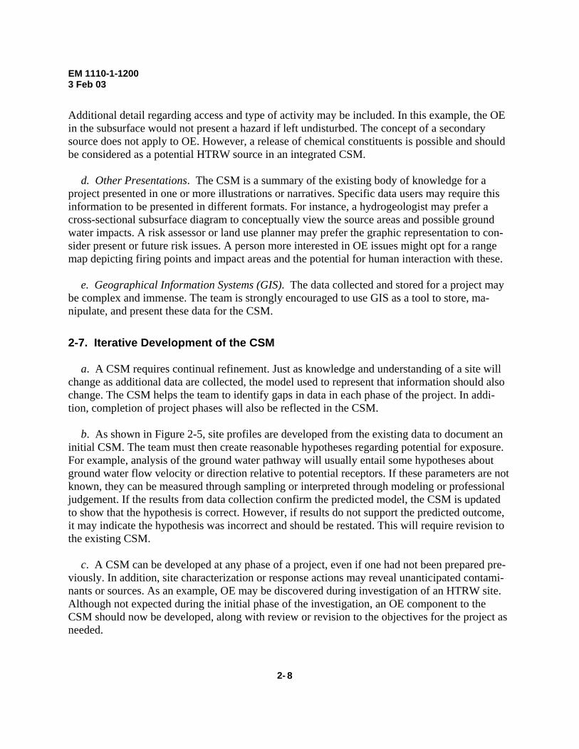
c. Military use of a site may change over time. The same range may be used for several differ-
ent activities and therefore contain a variety of OE items. Range dimensions and orientations may change as a result of target relocation (Figure 3-3). The team must consider the potential for changing use at each OE site.
Figure 3-3. Range Orientation over Time 3-4. Physical Profiles Physical properties of a site that affect the location, movement, detection, and recovery of OE are described in the Physical Profile for a site.
a. Location of OE. Location refers to both the areal (horizontal) extent as well as the vertical extent (depth) of OE.
3- 4
(1) Areal Extent of OE. This is related to the distribution of OE items from the use that occurred at that site. Usually, the type or limits of fire of a weapon system or a munition will provide a basis for areal distribution of the OE. Standard layouts for range boundaries may be used to help determine the probable location of OE. Terrain features are important when assess-ing the dimensions or potential hazards of some ranges, as these can limit the areal extent of OE. Natural or man-made barriers will produce a “shadow effect” on the distribution of ordnance fired at a target with a terrain feature as a backstop. An illustration of this is provided in Figure

EM 1110-1-1200 3 Feb 03
3-4. The standard layout for a range is shown in both design and as-built drawings for a former military installation. As shown on the as-built, the total area of the range is reduced by the terrain feature. Note this effect is more applicable to direct fire weapons (e.g., bazooka) rather that indi-rect fire systems such as mortar or artillery.
Figure 3-4. Terrain Effects on Range Dimensions
(2) Vertical Extent of OE. Subsurface conditions can affect the vertical extent of OE. For
instance, soil type, soil moisture, and vegetation are important physical factors in determining the penetration depth of certain ordnance. The team should attempt to determine the probable depth of penetration by the ordnance. This information is important to determining both the safety haz-ard from OE and the cost of detection or cleanup. Site-specific information includes soil type, soil moisture, topography, and vegetation. Weapons system information includes ordnance ge-ometry and weight, striking velocity, and angle of entry. Even with this information, investiga-tors should be aware that there may exist dramatic differences in penetration depth from the same ordnance. For example, loose, sandy soil will typically allow less penetration of similar ordnance than will dense clay. The depth or location of OE is an important factor when devel-oping clearance objectives for future land use.
b. Movement of OE. The team must evaluate physical processes that may affect movement of OE items. Erosion, scouring, or flooding of surrounding soil or sediment, frost heave, or tidal currents are natural processes that can cause movement of ordnance items from their original depth or location. The geology, geomorphology, and hydrology of the OE source area should be collected to assess this potential.
3-5

EM 1110-1-1200 3 Feb 03
c. Detection of OE. Many naturally occurring site conditions affect the detection of subsur-face OE. Physical characteristics affect specific detection instruments in different ways. Terrain and geology features may introduce electronic noise into the process, making detection difficult. Dense vegetation may affect the ability to get an instrument’s sensor close enough to the surface, thereby limiting its effectiveness. Terrain, vegetation, and soil composition are key data elements to be collected. These data will be used in the selection of appropriate geophysical instruments and methods.
d. Recovery of OE. Certain physical features affect the ability to access and recover OE at a site, and this information should be collected. These features can include excessive relief, rough terrain, wetlands and water bodies, and difficult vegetation. 3-5. Release Profiles Release mechanisms include those physical processes that contribute to the relocation of OE in the environment, after initial placement. An OE item tends to lie in place unless disturbed by ei-ther a natural process, as noted previously, or human activity. Construction, excavation, plowing or tilling, and surface soil or vegetation removal are examples of human activities that may relo-cate OE. Ordnance that was once deeply buried may become more accessible by removing overlying material. Any possibility of release of chemical constituents from OE items should be identified, considered as a source in an HTRW CSM, and addressed in an integrated CSM. 3-6. Land Use and Exposure Profiles The Land Use and Exposure Profiles are used to identify on-site and surrounding off-site land use and associated receptors. The Land Use Profile must identify the means of access or potential activities. The Exposure Profile identifies the available receptors at and near a site, and the ac-tivities whereby they may contact OE. Demographic information should also be included. This process will also be performed for any reasonably anticipated future land use. These profiles will assist in determination of the appropriate receptors to be evaluated in the pathway analysis. 3-7. Ecological Profiles The on-site or surrounding property should be described and its primary use documented. OE projects typically consider humans as the primary and often the only receptor to OE, because ecological receptors typically do not engage in activities that expose them to OE hazards. How-ever, site activities in support of OE projects, particularly vegetation removal and detonation of recovered OE, may significantly affect ecological receptors and should be evaluated.
3- 6
EM 1110-1-1200 3 Feb 03
3-8. Pathway Analysis Careful analysis of the profile information should allow the team to identify all source–receptor interactions for an OE project. The CSM will illustrate all potential exposure pathways (see Paragraph 2-6 for various CSM representations). For OE, an exposure pathway must include a source, access, activity, and a receptor. Interim measures, including access controls, source re-movals, or isolation methods, may interrupt the exposure pathway and should be considered in the analysis.
a. Sources. An OE source area is the location where ordnance or explosives are expected to be found, based on available information. The OE may be present as a result of direct military activities or placed there at some later time. Source areas were identified during generation of the Facility, Physical, and Release Profiles from available documentation or from direct evidence compiled during a site visit, or both. OE source areas are described by the following three com-ponents: the number and type of OE areas, the location and dimensions of each area, and the type and distribution (including depth) of OE within each area. Some processes such as frost heaving or erosion may change the location or distribution of OE items. This movement can increase the potential for direct contact.
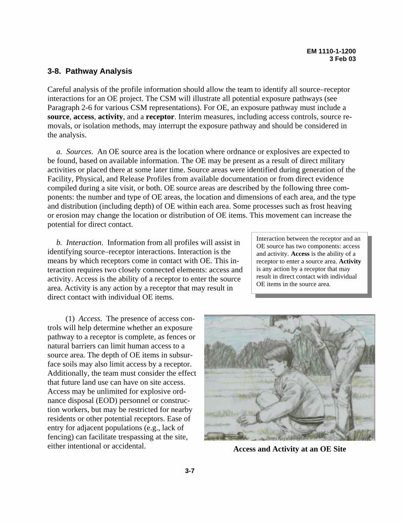
b. Interaction. Information from all profiles will assist in identifying source–receptor interactions. Interaction is the means by which receptors come in contact with OE. This in-teraction requires two closely connected elements: access and activity. Access is the ability of a receptor to enter the source area. Activity is any action by a receptor that may result in direct contact with individual OE items.
(1) Access. The presence of access con-trols will help determine whether an exposure pathway to a receptor is complete, as fences or natural barriers can limit human access to a source area. The depth of OE items in subsur-face soils may also limit access by a receptor. Additionally, the team must consider the effect that future land use can have on site access. Access may be unlimited for explosive ord-nance disposal (EOD) personnel or construc-tion workers, but may be restricted for nearby residents or other potential receptors. Ease of entry for adjacent populations (e.g., lack of fencing) can facilitate trespassing at the site, either intentional or accidental.
3-7
Interaction between the receptor and an OE source has two components: access and activity. Access is the ability of a receptor to enter a source area. Activity is any action by a receptor that may result in direct contact with individual OE items in the source area.
Access and Activity at an OE Site
EM 1110-1-1200 3 Feb 03
(2) Activity. The hazard presented by OE is caused by direct contact as a result of some
human activity. Site access without such activity does not present a hazard. Identification of OE exposure pathways should focus on current or future activities that bring humans into contact with the OE. Future use of OE land may result in intrusive activities (e.g., construction or agri-culture) that also increase the potential for contact.
c. Receptors. The receptors evaluated in the OE CSM were identified in the Land Use and Exposure Profile. Both current and future receptors must be considered for OE sites, and access controls are critical to this determination. Human receptors are categorized by their ability to ac-cess the site combined with the activities that potentially allow contact with OE. Construction workers, ranchers, EOD personnel, recreational users, trespassers, and residents are examples of potential receptors.
3- 8

EM 1110-1-1200 3 Feb 03
Chapter 4 Chapter 4 Development of a Conceptual Site Model for HTRW Projects Development of a Conceptual Site Model for HTRW Projects
4-1. Introduction 4-1. Introduction This chapter describes the steps in CSM development for an HTRW project addressing environ-mental contaminants. As with an OE project, CSM development follows the TPP process with establishment of project objectives and DQOs. The primary focus of the HTRW CSM is to illus-trate the interaction between contaminant sources and receptors. This is accomplished through development of the profile information (see Paragraph 2-4) and subsequent pathway analysis.
This chapter describes the steps in CSM development for an HTRW project addressing environ-mental contaminants. As with an OE project, CSM development follows the TPP process with establishment of project objectives and DQOs. The primary focus of the HTRW CSM is to illus-trate the interaction between contaminant sources and receptors. This is accomplished through development of the profile information (see Paragraph 2-4) and subsequent pathway analysis. 4-2. Profile Information Resources 4-2. Profile Information Resources
a. Identifying profile information available for an HTRW site is one of the most critical steps in developing the initial CSM. Historical and current site information may be obtained from maps, aerial photographs, existing reports, cross sections, land surveys, environmental studies, or laboratory analytical data. Procurement contracts or inventory records provide information about what items or materials were purchased and used by various departments. Operational manuals or procedures are also essential re-sources for information relating to how an activity was per-formed in the past. Landfill or burial pit disposal records, when available, offer invaluable data on what wastes may be present.
a. Identifying profile information available for an HTRW site is one of the most critical steps in developing the initial CSM. Historical and current site information may be obtained from maps, aerial photographs, existing reports, cross sections, land surveys, environmental studies, or laboratory analytical data. Procurement contracts or inventory records provide information about what items or materials were purchased and used by various departments. Operational manuals or procedures are also essential re-sources for information relating to how an activity was per-formed in the past. Landfill or burial pit disposal records, when available, offer invaluable data on what wastes may be present.
The quality of existing data must be evaluated before inclusion in the CSM. Some data may not meet quality standards for all uses. For example, data that are inadequate to evaluate risk may be acceptable to design a remedy. The decision tuse the data should be based on their applicability to the project objectives. However, all data sources should be described, copied, and archived for future reference.
reference.
o
b. Interviews with current or former site personnel will provide anecdotal information or
process knowledge about the site or specific activity. For military installations, the base historian, real property manager, and range managers should also be contacted. Local officials with the fire or law enforcement offices would typically have information if there have been responses to chemical spills or incidents.
b. Interviews with current or former site personnel will provide anecdotal information or process knowledge about the site or specific activity. For military installations, the base historian, real property manager, and range managers should also be contacted. Local officials with the fire or law enforcement offices would typically have information if there have been responses to chemical spills or incidents.
c. Site visits are highly recommended to identify significant features from all profile types for inclusion in the initial CSM. Local archives are often the best resource for information, and a site visit allows the opportunity to verify much of the written information. Visual evidence, such as soil stains or stressed vegetation, can directly indicate that HTRW contaminants are present.
c. Site visits are highly recommended to identify significant features from all profile types for inclusion in the initial CSM. Local archives are often the best resource for information, and a site visit allows the opportunity to verify much of the written information. Visual evidence, such as soil stains or stressed vegetation, can directly indicate that HTRW contaminants are present.
4-1
Sources of environmental contaminants should be described in terms of locations where the contamination exists and the types ofcontaminants present.

EM 1110-1-1200 3 Feb 03
4-3. Facility Profiles
A contaminant is usually defined as any substance that is potentially hazardous to human health or the environment and is present at concentrations above background levels. Contaminants may also be defined by regulatory concentrations, regardless of background levels.
a. Facility Profiles provide information to determine the source areas at a site. The source area for an HTRW project should be identified based on the presence of an environmental con-taminant. The team should be familiar with the historical operations at a site to recognize poten-tial unauthorized disposal sites or areas with a likelihood for incidental spills or releases. At HTRW sites, source areas typically include landfills, surface impoundments, fire training areas, process buildings, and underground storage tanks. All suspected source areas should be marked clearly on a site map, including the relationship to property boundaries.
b. Sampling data are typically the most reliable indicator of contamination sources at a site. In the absence of ade-quate sampling data, other methods may be used to develop reasonable hypotheses regarding potential sources. Known burial sites, soil stains, or stressed vegetation are signs of potential source areas and should be included in the profile information. 4-4. Physical Profiles
a. The factors that affect the fate and transport of the contaminants are identified in the Physi-cal Profile. This information includes soil type, soil properties, precipitation data, surface and ground water characteristics, and topography.
b. Physical profiles also describe site conditions important in determining exposure potential. Excessive topographic relief, dense vegetation, water bodies, or other physical characteristics may prevent or deter access to some sites, which limits potential for exposure.
c. Physical profiles are also important for identifying constraints to field activities and evalu-ating potential response actions. 4-5. Release Profiles
a. A contaminant is rarely immobile in the physical system; therefore, pathway analysis for environmental contaminants will usually require identification of a release mechanism. Release mechanisms include those physical processes that contribute to the introduction and distribution of a contaminant in the environment. This often leads to migration from the source area to an-other exposure medium.
4- 2
b. Multiple release mechanisms may exist for the same source. A drum of liquid contaminant may leak to soil as a
Release mechanisms should be identified for each source present at the site. Multiple release mechanisms may exist for each source area.

EM 1110-1-1200 3 Feb 03
primary release, then create a secondary release through percolation or infiltration. Volatilization of that contaminant from the soil may also occur, which adds another release mechanism from the primary source. Contaminated soil or sediment may become airborne or migrate through ero-sional processes to contaminate another medium. All potential release mechanisms and resulting contaminated media must be carefully evaluated.
c. Exposure media contain the source or become contaminated through migration of the con-taminant from the source area. Examples of exposure media are surface soil, subsurface soil, ground water, sediments, surface water, and air. The biotic medium can exist through uptake, accumulation, or concentration of contaminants by organisms and subsequent transport of that contaminant through the food chain. 4-6. Land Use and Exposure Profiles
a. The Land Use and Exposure Profiles are used to identify on-site and surrounding off-site land use and associated receptors. These profiles should also include locations of natural re-sources and how they are used.
b. The team should determine current use of the property and surrounding land. Demographic as well as sensitive subpopulation information is included in this profile. Any beneficial re-sources at the site must also be identified. This will aid in determining the appropriate receptors to be evaluated in the pathway analysis.
c. The exposure profile identifies the available receptors at and near a site. A receptor is a person or population that is or may be exposed to a release. Both current and potential future re-ceptors must be identified. 4-7. Ecological Profiles The Ecological Profile for an HTRW project includes a description and use of the natural habi-tats at and surrounding the site. Identification of receptors is usually enhanced by use of maps that show the ecological profile and land use surrounding the facility and contaminant migration routes from the source. Ecological receptors may include individual organisms, populations, communities, or habitats and ecosystems. Threatened and endangered species, as well as migra-tory species, must be identified if they are present.
An HTRW exposure pathway requires a source, an exposure medium, an exposure route, and a receptor. If any one of these is absent, that pathway is incomplete and no risk can be assigned. This effort must be documented to demonstrate that the potential for risk from this pathway has been evaluated.
4-8. Pathway Analysis
4-3
Careful analysis of the profile information should allow the team to identify all source–receptor interactions for an HTRW project, for both current and reasonably an-ticipated future land use. The CSM will illustrate all po-tential exposure pathways (see Paragraph 2-6 for various CSM representations). An exposure pathway is the

EM 1110-1-1200 3 Feb 03
course a physical or chemical agent takes to contact a receptor. Each pathway must include a source, an exposure medium, an exposure route, and a receptor. The pathway may also in-clude a release mechanism (e.g., volatilization) and a transport medium (e.g., air), if the point of exposure is not at the same location as the source. It is important to remember that certain activi-ties, such as soil excavation, can create a complete exposure pathway where one does not cur-rently exist.
a. Sources. Source areas are identified when the Facility, Physical, and Release Profiles are generated, and will be used for the pathway analysis.
b. Interaction. For HTRW sites, the source–receptor interaction requires that exposure media and exposure routes be evaluated. Information from all profiles will assist in identifying these interactions.
(1) Exposure Media. Exposure media are those that contain the source, or those media that become contaminated through migration of the contaminant from the source area.
(a) Exposure to soil (surface and subsurface) is important where there is potential for receptor contact with contamination or for contaminant migration into another medium. The team must determine the depth of contamination, the potential for human or biotic contact with the contamination, and the migration potential of the contaminant.
(b) Exposure to ground water is important when contaminated ground water is used for domestic purposes. Contaminants are rarely released directly into ground water. Typically, ground water is contaminated by migration from another medium. The team must consider fac-tors that affect the likelihood of a contaminant reaching ground water, such as depth to the aqui-fer and permeability of the overlying strata. Contaminant migration within the aquifer must con-sider transmissivity of the water-bearing unit as well as fate and transport properties of the contaminant.
(c) Exposure to sediments is most important to ecological receptors, as sediment-dwelling organisms typically serve as a food source for higher trophic level organisms. Human receptors can be exposed under certain conditions, such as through wading or swimming.
(d) Exposure to surface water is important when contamination is released directly to
the surface water body, or through contaminant migration from another medium (e.g., surface soil or ground water). Human receptors can be exposed through recreational activities (e.g., swimming, wading, or fishing) or domestic uses of the surface water.
4- 4
(e) Exposure to air is important when particulate dispersion of contaminated soils or sediments, release of volatile compounds from soils or sediments, or volatilization of contami-nants from surface water is possible. Prevailing wind directions should be determined to measure potential for receptor exposure to this medium.

EM 1110-1-1200 3 Feb 03
(f) The biotic medium is important when considering the potential for transfer of con-
taminants through the food chain. Additionally, bioaccumulation and bioconcentration of some contaminants in plants or animals can result in exposure of other receptors to harmful contami-nant concentrations.
(2) Exposure Routes. Exposure routes are those processes by which a contaminant or physical agent comes in contact with a receptor. For most environmental contaminants, these processes include ingestion, inhalation, and dermal contact. More than one exposure route may exist for any single pathway. For example, a receptor may be exposed to contaminants in surface water through dermal contact and incidental ingestion while swimming. Inhalation of volatile compounds released from water is a third potential exposure route in this scenario, depending on the properties of the contaminant. Multiple receptors may be, and typically are, exposed through a single exposure route. Ingestion of contaminated surface water is as much a concern for terres-trial or aquatic wildlife as for humans.
c. Receptors. The receptors evaluated in the HTRW CSM were identified in the Land Use and Exposure Profile, as well as the Ecological Profile. The team must consider both human and ecological receptors. Evaluation of actual and potential receptors will consider both current and reasonably anticipated future land use. In addition, human receptors are typically subdivided into several categories to represent varying degrees of potential exposure. These may include resi-dents, site workers, construction workers, recreational users, and trespassers. The probability, frequency, and duration of each receptor’s exposure to the contaminant are assessed in this man-ner.
4-5

EM 1110-1-1200 3 Feb 03
Chapter 5 Development of an Integrated Conceptual Site Model for OE and HTRW Projects
5-1. Introduction
a. This chapter describes the steps in CSM development for properties whose historical mili-tary use creates a potential for OE and HTRW that may require assessment and response. When the potential for OE and HTRW exists on a site, then an integrated CSM should be developed. An integrated CSM addresses all source–receptor interactions for both OE and HTRW from all sources at a site. Typically, the HTRW project will follow the OE project phase. In such cases, data needs for the HTRW project must be communicated early on to ensure that OE project efforts support those needs when possible. As noted in Paragraph 2-3, the PM should assemble a team to address both OE and HTRW issues, and oversee the in-tegration of overlapping data needs. An integrated CSM will facilitate concurrent OE and HTRW data collection.
b. The overall approach to developing the CSM is the sameOE site and an HTRW site: profile information is collected anlyzed. CSM development is a tool in the TPP process. The teaing profile information, prepare an initial CSM, develop projeject, and collect necessary data specific to fulfilling those obje 5-2. Profile Information Resources OE and HTRW project phases have distinct information needsboth. The information needs described in the following sectionand HTRW data needs may overlap. These summaries are notprovide a general guide to information needs that may be sharinformation resources for OE and HTRW sites described in prneed to be shared by all team members. 5-3. Facility Profiles
a. Facility Profiles provide information to help determine tboth OE and HTRW may be present, the team needs to gathertion that supports both OE and HTRW projects.
5-1
b. A primary information need common to CSM developmdelineation of the OE use areas, OE area type, and the type anMany OE areas have the potential not only for OE, but also exsult in environmental contamination. Explosives and propellan
Early and ongoing coordination between OE and HTRW personnel is critical to efficient planning and execution of an integrated project. Ideally, during the early stages of the project, OE personnel will coordinate with the HTRW team members to ensure data collected will meet their DQOs.
for an integrated project as for an d pathways are subsequently ana-m must collect and analyze exist-ct DQOs for that phase of the pro-ctives.
and some that are common to s represent some areas where OE
specific to any project or site, but ed by the team members. Profile evious chapters will be used, and
he source areas at a site. When and sort facility profile informa-
ent for OE and HTRW projects is d distribution of OE in each area. plosives constituents that may re-ts from low-order detonations or
EM 1110-1-1200 3 Feb 03
prolonged use of an area have been shown to affect soil, sediment, and ground water media at some locations.
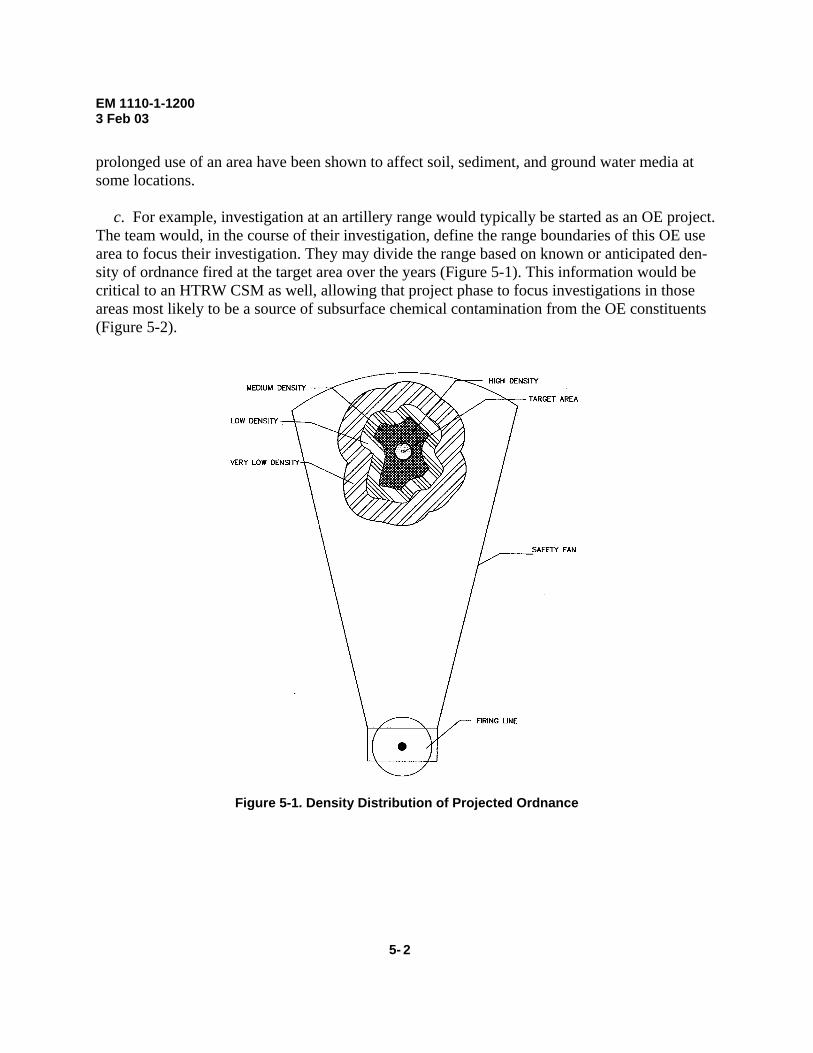
c. For example, investigation at an artillery range would typically be started as an OE project.
The team would, in the course of their investigation, define the range boundaries of this OE use area to focus their investigation. They may divide the range based on known or anticipated den-sity of ordnance fired at the target area over the years (Figure 5-1). This information would be critical to an HTRW CSM as well, allowing that project phase to focus investigations in those areas most likely to be a source of subsurface chemical contamination from the OE constituents (Figure 5-2).
Figure 5-1. Density Distribution of Projected Ordnance
5- 2

EM 1110-1-1200 3 Feb 03
Mortar Range Mortar Range 3-D
ImpactArea
Burn/Burial Pits Groundwater
Firing Points
Figure 5-2. Areas of Potential OE and HTRW Distribution at a Mortar Range
d. Many locations with OE also have a potential for chemical contamination. For example,
open burn (OB) units often used fuels as accelerants when excess ordnance is destroyed. Simi-larly, the manufacture of explosives at ammunition plants generated large quantities of waste rinse water that was retained in impoundments and often releases contaminants to other media.
e. The type of OE used at a site is an important information need for an integrated project. This information is critical to understanding the explosive hazards and the possible chemical contamination resulting from OE constituents. All team members will need to work together to identify explosives and propellants by their precise composition. Changes in the chemical com-position of constituents occur over time and from exposure to the environment. Explosive D (ammonium picrate), for instance, degrades to picric acid and other constituents when exposed to moisture, and can produce explosive picric salts that are extremely shock sensitive. 5-4. Physical Profiles OE and HTRW projects can share most physical profile information. Site topography, geology, meteorology, and hydrology data are examples of common data needs. Soil type and soil proper-ties (moisture content, corrosivity, pH, etc.) are important for evaluation of depth of OE and the fate and transport of chemical contamination. The same type of OE use area in a different physi-cal setting will present different environmental challenges. Because physical profiles also affect access to OE, this information must be clearly presented.
5-3

EM 1110-1-1200 3 Feb 03
5-5. Release Profiles Release mechanisms include those natural processes or human activities that relocate OE or in-troduce and distribute an HTRW contaminant in the environment. For HTRW, this often leads to migration from the source area to another exposure medium.
5-6. Land Use and Exposure Profiles Land use and receptor information is common to both OE and HTRW projects. The team must consider both current and reasonably anticipated future land use so that all source–receptor inter-actions can be evaluated. Although the source–receptor interactions may differ, understanding receptor populations and their activities is necessary for either investigation. 5-7. Ecological Profiles The Ecological Profile will identify surrounding land and habitats and will aid the team in de-termining potential ecological receptors. Special use areas (e.g., fisheries) as well as protected species potentially impacted by the site should be described.
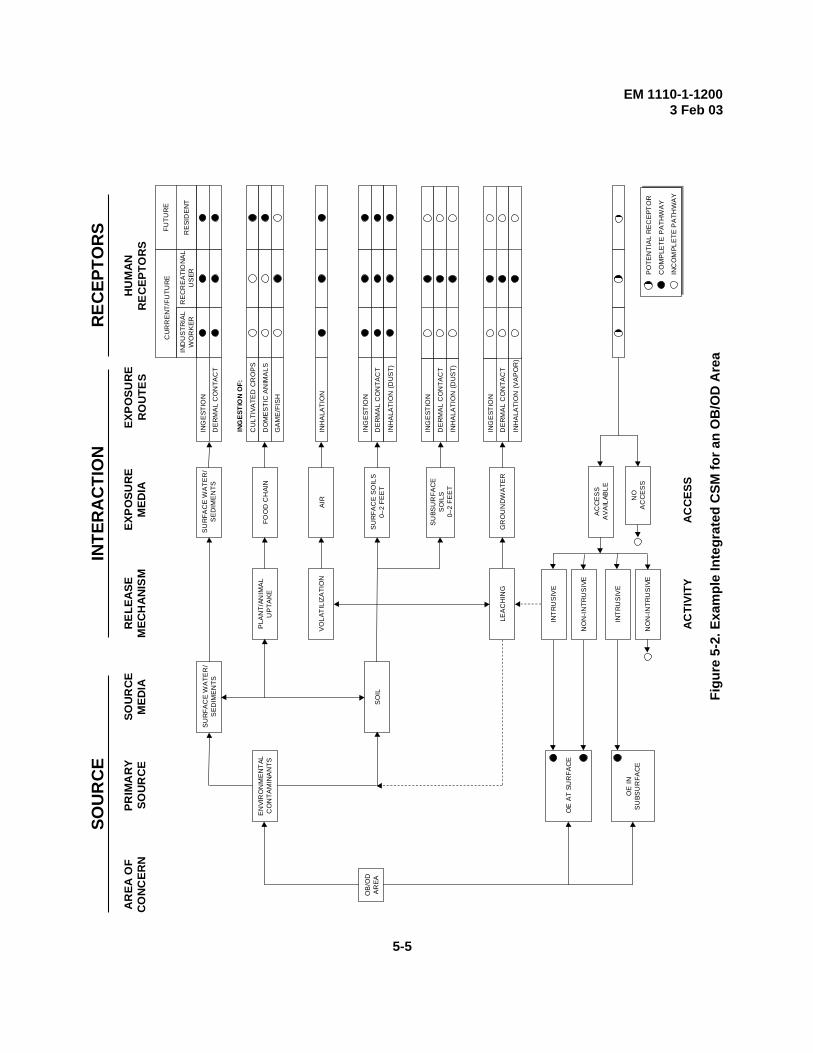
5-8. Pathway Analysis The Pathway Analysis for an integrated site will allow the team to identify all source–receptor interactions for both the OE and the HTRW components of the project. Analyzing exposure pathways for OE or HTRW projects requires linking a source to a receptor, although the interac-tions differ. All complete exposure pathways will be illustrated in the integrated CSM. Figure 5-2 presents an example integrated CSM for an OB/open detonation (OD) area (the generation of this integrated CSM is explained in Appendix D).
a. Source. All sources can be identified by analysis of the Facility, Physical, and Release Profiles. The team needs to be aware that many types of OE use areas can provide a source of HTRW, and ensure that the integrated CSM evaluates these sources. Common sources must be dealt with in an integrated way, and will become part of an integrated CSM.
b. Interaction. Information from all profiles will assist in identifying source–receptor inter-actions. Analysis of the interactions for an integrated CSM consists of separate evaluations for the OE and the HTRW component. For either component, the interaction has elements that must be present for the pathway to be complete. Those interactions forming complete pathways will be shown in the integrated CSM.
c. Receptors. Receptors are identified from the Land Use and Exposure Profile, as well as the Ecological Profile. The evaluation of receptors must take into account current and future land use. Site restrictions for OE may also limit or alter the receptors evaluated for the HTRW com-ponent. The team needs to consider all receptors with the potential for exposure to sources at the site.
5- 4
ING
EST
ION
DE
RM
AL
CO
NTA
CT
CU
LTIV
ATE
D C
RO
PS
DO
ME
STI
C A
NIM
ALS
GA
ME
/FIS
H
INH
ALA
TIO
N
ING
EST
ION
DE
RM
AL
CO
NTA
CT
INH
ALA
TIO
N (D
US
T)
ING
EST
ION
DE
RM
AL
CO
NTA
CT
INH
ALA
TIO
N (D
US
T)
ING
EST
ION
DE
RM
AL
CO
NTA
CT
INH
ALA
TIO
N (V
AP
OR
)
IND
US
TRIA
LW
OR
KER
CU
RR
EN
T/FU
TUR
E
RE
CR
EA
TIO
NA
LU
SER
FUTU
RE
RE
SID
EN
T
HUM
AN
REC
EPTO
RS
SU
RFA
CE
WA
TER
/S
ED
IME
NTS
SU
RFA
CE
WA
TER
/S
ED
IME
NTS
FOO
D C
HAI
NP
LAN
T/AN
IMA
LU
PTA
KE
AIR
VO
LAT
ILIZ
ATI
ON
SU
RFA
CE
SO
ILS
0–2
FEE
T
SU
BSU
RFA
CE
SO
ILS
0–2
FEE
T
GR
OU
ND
WA
TER
EXPO
SURE
RO
UTE
SEX
POSU
RE
MED
IARE
LEAS
EM
ECH
ANIS
MSO
UR
CE
MED
IAPR
IMA
RYSO
URC
EA
REA
OF
CONC
ERN
EN
VIR
ON
ME
NT
ALC
ON
TAM
INA
NTS
SO
IL
LEA
CH
ING
INT
RU
SIV
E
OE
AT
SUR
FAC
E
OB
/OD
AR
EA
ING
ESTI
ON
OF:
CO
MP
LETE
PA
THW
AY
INC
OM
PLE
TE P
ATH
WA
Y
SOU
RC
EIN
TER
AC
TIO
NR
ECEP
TOR
S
AC
CE
SS
AV
AIL
ABLE
NO
AC
CE
SS
PO
TEN
TIA
L R
EC
EPT
OR
NO
N-IN
TRU
SIV
E
INT
RU
SIV
EO
E IN
SU
BSU
RFA
CE
NO
N-IN
TRU
SIV
E
ACC
ESS
ACTI
VITY
EM 1110-1-12003 Feb 03
5-5
Figu
re 5
-2. E
xam
ple
Inte
grat
ed C
SM fo
r an
OB
/OD
Are
a

EM 1110-1-1200 3 Feb 03
Appendix A Bibliography ASTM, 1995. Standard Guide for Developing Conceptual Site Models for Contaminated Sites, ASTM E 1689-95, American Society for Testing and Materials, Philadelphia, PA. Department of Defense (DoD) Instruction 6055.14, “Unexploded Ordnance Safety on Ranges,” 23 January 1998. Department of the Army, U.S. Marine Corps, 1994. Unexploded Ordnance (UXO) Procedures, Field Manual No. 21-16, Fleet Marine Force Manual 13-8-1. Naval Explosive Ordnance Disposal Technology Division, Unexploded Ordnance (UXO): An Overview, October 1996. Report of the Defense Science Board Task Force on Unexploded Ordnance (UXO) Clearance, Active Range UXO Clearance, and Explosive Ordnance Disposal (EOD) Programs, Office of the Undersecretary of Defense for Acquisition and Technology, April 1998. Tetra Tech Em, Inc., 2001. Appendix A Draft Report on the Development of a Conceptual Model for the Characterization of Military Munitions at Camp Edwards Massachusetts, prepared for National Guard Bureau, Army Environmental Division, Arlington, VA. U.S. Army, 2002. Bioconcentration, Bioaccumulation and Biomagnification of Nitroaromatic and Nitramine Explosives and their Breakdown Products, U. S. Army Center for Health Promo-tion and Preventive Medicine Toxicology Study No. 87-MA-4677-01, March. U.S. Army (15 October 1983) Policies and Procedures for Firing Ammunition for Training, Target Practice, and Combat. Army Regulation AR 385-63. USEPA, 1989. Risk Assessment Guidance for Superfund, Human Health Evaluation Manual, Part A, Interim Final, EPA/540/1-89/002. USEPA, 1994. Guidance for the Data Quality Objectives Process, QA/G-4. USEPA, 2000. Data Quality Objectives Process for Hazardous Waste Site Investigations, EPA/600/R-00/0007.
A-1

EM 1110-1-1200 3 Feb 03
Appendix B Acronyms And Definitions
ASR Archives Search Report ASTM American Society for Testing and Materials CSM Conceptual Site Model. CWM Chemical Warfare Material DoD U.S. Department of Defense DQO Data Quality Objective EM Engineering Manual EOD Explosive Ordnance Disposal EPA U.S. Environmental Protection Agency ER Engineer Regulation GIS Geographical Information Systems HTRW Hazardous, Toxic, and Radioactive Waste IDA Industrial Development Authority OB Open Burn OD Open Detonation OE Ordnance and Explosives PDT Project Delivery Team PM Project Manager TPP Technical Project Planning USACE U.S. Army Corps of Engineers UXO Unexploded Ordnance Access The ability of a receptor to enter a source area. Activity Any action by a receptor that may result in direct contact with individual OE items in the source area. Archives Search Report (ASR) An ASR is an evaluation of past OE activities at an installation. The purpose of an ASR is to as-semble historical records and available data and assess potential ordnance presence. Conceptual Site Model (CSM) The CSM is a description of a site and its environment that is based on existing knowledge. It describes sources of OE or HTRW at a site; actual, potentially complete, or incomplete exposure pathways; current or reasonably anticipated future land use; and potential receptors. The source–receptor interaction is a descriptive output of a CSM. The CSM serves as a planning instrument, a modeling and data interpretation aid, and a communication device among the team.
B-1

EM 1110-1-1200 3 Feb 03
Data Implementor Technical personnel (e.g., chemists, engineers, geologists, scientists) who contribute to the data implementor perspective are responsible for identifying sampling and analysis methods suitable for satisfying the data users’ data needs. Data implementors are generally referred to as either a sampling or analysis type of data implementor. Data implementor is a classification used in EM 200-1-2, Technical Project Planning (TPP) Process. Data Quality Objective (DQO) DQOs are qualitative and quantitative statements that clarify study objectives, define the appro-priate type of data, and specify tolerable levels of potential decision errors that will be used as the basis for establishing the quality and quantity of data needed to support decisions. They are project-specific statements that describe the intended data use(s), the data need requirements, and the means to achieve them (sampling and analysis) for each data point. DQOs become the for-mal documentation of the data quality requirements. Data User Data users are technical and other personnel responsible for engineering, scientific, and legal evaluations that are the basis for site decisions. Progress to site closeout typically requires the collaborative involvement of many technical disciplines to represent data user perspectives of risk, compliance, remedy, and responsibility. Data users are responsible for determining data needs required to satisfy the project objectives. Data user is a classification used in EM 200-1-2, Technical Project Planning (TPP) Process. Decision-Maker Decision-makers (i.e., customer, project manager, regulators, and stakeholders) each have spe-cific interests in the outcome of site-related activities. The most important responsibility of each decision-maker is to participate in the team’s efforts to identify and document project objectives during early phases of the planning process. Decision-Maker is a classification used in EM 200-1-2, Technical Project Planning (TPP) Process. Exposure Contact of an organism with a chemical or physical agent. Exposure is quantified as the amount of the agent available at the exchange boundaries of the organism (e.g., skin, lungs, organs) and available for absorption. (EPA/540/1-89/002) Exposure Pathway
B- 2
The course a chemical or physical agent takes from a source to an exposed organism. An expo-sure pathway describes a unique mechanism by which an individual or population is exposed to chemical or physical agents at or originating from a site. Each exposure pathway includes a source or release from a source, an exposure point, and an exposure route. If the exposure point differs from the source, a transport/exposure medium (e.g., air), or media, also is included. (EPA/540/1-89/002)

EM 1110-1-1200 3 Feb 03
Exposure Point A location of potential contact between an organism and a chemical or physical agent. (EPA/540/1-89/002) Exposure Route The way a chemical or physical agent comes into contact with an organism (e.g., ingestion, in-halation, dermal contact). (EPA/540/1-89/002) Interaction Ways that receptors come into contact with a source. Media Air, surface water, sediment, soil, and ground water are the most common types of environ-mental media at a site. Media can be any naturally occurring environmental material that can be affected by contamination at a site. Ordnance and Explosives (OE) Ordnance and explosives consists of either (1) ammunition, ammunition components, chemical or biological warfare material or explosives that have been abandoned, expelled from demolition pits or burning pads, lost, discarded, buried, or fired (i.e., UXO) and that are no longer under ac-countable record control of any DoD organization or activity or (2) explosive soil, where any mixture of explosives in soil, sand, clay, or other solid media is at such concentrations that the mixture itself is explosive. (EP 1110-1-18) Project Delivery Team (PDT, Team) The PDT is responsible and accountable for ensuring that effective, coordinated actions combine to deliver the completed project according to the Project Management Plan. The PDT shall con-sist of everyone necessary for successful development and execution of all phases of the project. PDT members will include the customer, the PM, representatives from various technical disci-plines within USACE, stakeholders, representatives from other federal or state agencies, vertical members from division and headquarters, and others necessary to effectively develop and deliver a successful project. The team composition can vary greatly, depending on the specific goals and expectations of the customer. The USACE team members may come from any functional area or geographic location, and are selected solely on their ability to successfully plan and execute their portion of the project. They may be on the team full time or only on a temporary basis. Project Objectives Project objectives are the short- and long-term site issues to be addressed and resolved at a site. Satisfying or resolving the project objectives, based on the underlying regulations or site deci-sions, is the purpose of all site activities. Most project objectives are a consequence of the gov-erning statutes and applicable regulations.
B-3
EM 1110-1-1200 3 Feb 03
Receptor A receptor is an organism (human or ecological) that contacts a chemical or physical agent. Source Sources are those areas where OE or HTRW has entered (or may enter) the physical system. Stakeholders Individuals and organizations that are involved in or may be affected by the project. Technical Project Planning (TPP) Process The process for designing data collection programs at HTRW sites. The TPP process helps en-sure that the requisite type, quality, and quantity of data are obtained to satisfy project objectives that lead to informed decisions and site closeout. The four phase TPP process is a comprehensive and systematic planning process that will accelerate progress to site closeout within all project constraints. The TPP process can be used from investigation through closeout at small, simple sites, as well as large, complex sites. The TPP process is a critical component of the USACE quality management system that meets the American National Standard Institute for planning collection and evaluation of environmental data. The TPP process is documented in EM 200-1-2, Technical Project Planning (TPP) Process. Unexploded Ordnance (UXO) UXO is defined as military munitions that have been primed, fuzed, armed, or otherwise pre-pared for action, and that have been fired, dropped, launched, projected, or placed in such a manner as to constitute a hazard to operations, installation, personnel, or material and that remain unexploded either by malfunction, design, or any other cause. (EP 1110-1-18)
B- 4

EM 1110-1-1200 3 Feb 03
Appendix C Range Operations Overview C-1. General When developing a CSM for a former military site it is important for the team to understand the basics of design, operation, and maintenance of training ranges. Different parts of ranges were used for different operations with distinctly different hazards existing at each of these locations. This section presents only an overview of the most important elements of range operations. C-2. Storage Areas These are typically located near, but not within, a range. Types of storage areas include perma-nent or temporary facilities for stockpiling munitions and munitions components. These facilities can include warehouses, bunkers, magazines, or vehicles. Munitions stored in these facilities are normally in their shipping containers or configurations and are seldom fuzed. They represent very little hazard of inadvertent detonation. Though not a normal practice, unwanted or unserv-iceable munitions were occasionally buried in or near storage areas. C-3. Firing Points These are fixed locations or areas where munitions are prepared for use and then fired. Munitions come in many different configurations, but normally include the filler (typically explosive) and a fuzing system to initiate the explosive. In addition, many munitions include a propellant charge designed to propel them to their target. For most munitions, at least two, and often all three of these main components were stored separately. They were only combined and configured for use at the firing point. In many instances there were excess components, especially propellant, re-sulting from the use of munitions at firing points. Excess propellants were typically burned near the firing point, and other excess components were either returned to storage, destroyed through burning or detonation, or buried. C-4. Targets
C-1
These are particular locations within a larger impact area where munitions are intended to land and function. Targets can consist of almost anything, including excess military or civilian vehi-cles, old appliances, wooden or cardboard structures, geographic features, or map coordinates with no defining features. Most munitions fired at a target functioned as intended, and therefore represent no further safety hazard. However, a significant percentage—typically from 1 to 20%—did not function as intended. Either the munitions did not explode at all, or only a part of the filler was consumed when the munitions functioned. When munitions were fired but inad-vertently did not function as designed, they are categorized as UXO. UXO can be extremely dangerous and must never be touched by anyone other than trained personnel. Impact areas con-taining UXO should be regarded as extremely hazardous sites. At many larger range complexes,

EM 1110-1-1200 3 Feb 03
several ranges may share a common impact area. As indicated by the example in Figure C-1, determination of the OE hazards in an impact area can be quite complex. Numerous weapons systems firing a different types of ammunition over a time have resulted in an impact area that is difficult to characterize. Both OE hazards and environmental contaminants must be evaluated. UXO (armed or fuzed) and residual OE compounds are likely to be present.
C o m b a t A rea
C e n t ra lI m p a c t A re a
S k e et R an g e
B R an g e
G rav ity A n t i- tan k R an g e
B R a n g e
E R a n g e
C R an g e
D R an g e
A R an g e
U R an g e
L -2 R an g e
L -3 R a n g e
R R an g eQ R an g e
O R an g e
N R an g e
L R an g eT R an g e
I B C
D e m o A rea
L -4 R an g e
M u s k e tr y R an g e
M o ck V i ll a g e
5 0 0 Y ardR if le R a n g e
P R a n g e
O R an g e
N R an g e
L R an g e
J -3 R an g e
M R an g e
K d R a n g eK R a n g e
J R a n g e
I R a n g eH R an g e
A n t i - a i rc ra f t M in ia tu re R an g e
G R an g e
C o m b a t A rea
Figure C-1. Typical Range Complex Impact Area
C-5. OB/OD Areas
C- 2
These are locations where munitions are destroyed, usually within a permitted facility. Typically, excess stockpile munitions were destroyed at OB/OD areas. However, UXO from target and im-pact areas are sometimes moved to OB/OD areas for destruction as well. Basically, UXO can be divided into two groups: those that trained personnel determine are moveable, and those that are determined unsafe to move. Those that are unsafe to move are destroyed where they are found by detonating in place. UXO and other munitions that are determined to be safe to move can be ei-

EM 1110-1-1200 3 Feb 03
ther detonated in place or moved to another location, often an OB/OD facility, for destruction. Because of safety concerns, UXO, whether “safe to move” or not, are never disassembled and their components recovered. Demolition operations are not always effective. Entire munitions, as well as dangerous components, can remain. Like target areas, demolition areas should be re-garded as extremely hazardous sites.
C-3

EM 1110-1-1200 3 Feb 03
Appendix D Development of an Integrated CSM
D-1. Introduction The following is a hypothetical example for demonstration only. It is intended to illustrate how a team might begin the process of developing an integrated CSM. The reader is cautioned that CSM development should be based on site-specific parameters and information. D-2. Background
a. Former Camp Swampy was a World War II facility for training of U.S. Army troops. The facility was declared excess in 1956, and in 1957 the property transferred to the local township Industrial Development Authority (IDA). The IDA transferred a small parcel in the southeast corner to a private landowner 2 years later. The remaining property has been subsequently leased to several commercial enterprises for various uses. An ASR conducted in 1993 identified a mor-tar range and OB/OD area at the former camp. Surface clearance had been conducted prior to transfer, and no OE items were known to remain at the site. In 2001, several explosions were heard during a prescribed burn in a forested area of the former installation. The detonations were suspected to be from mortar rounds on the property. Presented with this information, the IDA contacted the local district of the USACE for assistance. Since no extensive sampling investiga-tion had been conducted prior to the transfer, the District initiated an integrated OE/HTRW in-vestigation.
b. A PM from the geographic District was assigned overall management of the former Camp Swampy investigation. The OE project will precede the HTRW investigation. To initiate the project, the PM assembled a PDT (team) consisting of OE specialists, HTRW specialists, state and federal regulators, and representatives from the IDA, business owners, and local landowners at the site. The team’s first order of business was to establish goals and objectives of the investi-gation to follow. One of the objectives was to develop a CSM to capture the source–receptor in-teractions to guide future data collection efforts. The team gathered all historical information available for the site, including aerial photographs from the operating period of the facility. The team then organized the available information into the following profiles. D-3. Facility Profile
D-1
a. The team was able to determine current use and ownership of former Camp Swampy from existing information and a site visit. The majority of the 18,000-acre facility is leased from the IDA by a timber products company and used to grow pine trees. The timber products company also sub-leases this land to a local hunting club, which has a cabin on the northern boundary of the property. The acreage is not fenced, but there are locked gates across access roads through the property. The industrial area (the former cantonment area) still has several buildings that are in use at the site, also leased through the IDA. A metal fabrication shop occupies one building,
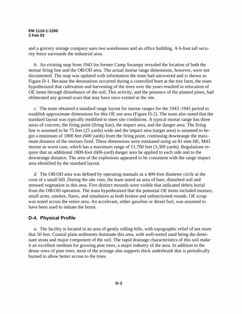
EM 1110-1-1200 3 Feb 03
and a grocery storage company uses two warehouses and an office building. A 6-foot tall secu-rity fence surrounds the industrial area.
b. An existing map from 1943 for former Camp Swampy revealed the location of both the mortar firing line and the OB/OD area. The actual mortar range dimensions, however, were not documented. The map was updated with information the team had uncovered and is shown as Figure D-1. Because the detonations occurred during a controlled burn at the tree farm, the team hypothesized that cultivation and harvesting of the trees over the years resulted in relocation of OE items through disturbance of the soil. This activity, and the presence of the planted pines, had obliterated any ground scars that may have once existed at the site.
c. The team obtained a standard range layout for mortar ranges for the 1943–1945 period to establish approximate dimensions for this OE use area (Figure D-2). The team also noted that the standard layout was typically modified to meet site conditions. A typical mortar range has three areas of concern, the firing point (firing line), the impact area, and the danger area. The firing line is assumed to be 75 feet (25 yards) wide and the impact area (target area) is assumed to be-gin a minimum of 1800 feet (600 yards) from the firing point, continuing downrange the maxi-mum distance of the mortars fired. These dimensions were estimated using an 81-mm HE, M43 mortar as worst case, which has a maximum range of 11,700 feet (3,300 yards). Regulations re-quire that an additional 1800-foot (600-yard) danger area be applied to each side and to the downrange distance. The area of the explosions appeared to be consistent with the range impact area identified by the standard layout.
d. The OB/OD area was defined by operating manuals as a 400-foot diameter circle at the crest of a small hill. During the site visit, the team noted an area of bare, disturbed soil and stressed vegetation in this area. Five distinct mounds were visible that indicated debris burial from the OB/OD operation. The team hypothesized that the potential OE items included mortars, small arms, smokes, flares, and simulators as both broken and unfunctioned rounds. OE scrap was noted across the entire area. An accelerant, either gasoline or diesel fuel, was assumed to have been used to initiate the burns. D-4. Physical Profile
a. The facility is located in an area of gently rolling hills, with topographic relief of not more that 50 feet. Coastal plain sediments dominate this area, with well-sorted sand being the domi-nant strata and major component of the soil. The rapid drainage characteristics of this soil make it an excellent medium for growing pine trees, a major industry of the area. In addition to the dense rows of pine trees, most of the acreage also supports thick underbrush that is periodically burned to allow better access to the trees.
D- 2

EM 1110-1-12003 Feb 03
D-3
Fi
gure
D-1
. Pre
limin
ary
Site
Map

EM 1110-1-1200 3 Feb 03
D- 4
Buffer Zone
Firing Line
Figure D-2. Mortar Range

EM 1110-1-1200 3 Feb 03
b. The team reviewed available state records of residential drinking water wells in the sur-rounding area and determined that ground water averaged 20–25 feet below ground surface. There are no wells in the former cantonment area, but it was discovered that a shallow water well exists at the cabin, presumably used during the hunting season.
c. A small creek originates about 150 feet southeast of the OB/OD area. Some red staining, thought to be iron oxide, was noted seeping from the creek bank downhill of the OB/OD area. The creek joins a river about 1.5 miles west of the facility. Despite the former camp’s name, there are no wetland areas located at the property. D-5. Release Profile Using the Facility Profile information, the team identified the OE areas of concern as the former mortar range and the OB/OD area. The mortar range was further divided into two areas based on typical use, the hazards associated with that use, and potential source materials. These two areas are the firing line and the impact/target area. The probable locations of all source areas were placed on the site map for later confirmation. D-6. Land Use and Exposure Profile
a. The team documented use of the former mortar range as managed forest lands, and the former OB/OD area as currently unused. The on-site population includes workers at the indus-trial area, but interviews with these personnel indicated that they do not utilize either area during work hours. Timber company workers occupy the areas of concern on those occasions when planting, harvesting, or the controlled burns occur. Recreational use (hunting and hiking) was also noted, although the team has not yet identified the extent of this site use.
b. The surrounding land use is agricultural, with 12 single-family homes located within a 3-mile radius of the property. These residents rely on private wells for their drinking water. The industrial area, however, is serviced by the municipal water supply system. The small creek trav-ersing the site discharges to a river that is used extensively for recreation (boating, swimming, and fishing). D-7. Ecological Profile The Ecological Profile for former Camp Swampy includes a description of the managed pine forest habitat that occupies most of the acreage. Ecological receptors include game animals (e.g., deer, turkeys) and other terrestrial animals. Fish and other aquatic organisms inhabit the down-stream river, which serves as a popular recreation area. No threatened or endangered species are known to utilize the area.
D-5
EM 1110-1-1200 3 Feb 03
D-8. Pathway Analysis Analysis of the profile information should allow the team to identify all source–receptor interac-tions (exposure pathways) for the site. An exposure pathway is the course a physical or chemical agent takes to contact a receptor. For OE, an exposure pathway must include a source, access, activity, and a receptor. Each pathway for HTRW must include a source, an exposure medium, an exposure route, and a receptor. The pathway may also include a release mechanism (e.g., volatilization) and a transport medium (e.g., air), if the point of exposure is not at the same loca-tion as the source. In preparation for the CSM, the team compiled the following. D-9. OE Sources Three source areas were identified. They are the firing line at the mortar range, the mortar impact area, and the OB/OD area. OE is expected in subsurface soils at the firing line, and both surface and subsurface soils at the impact area and OB/OD area. The exposure media for the mortar range areas are expected to include surface and subsurface soils, as well as ground water from leaching of the OE constituents and accelerants. The same exposure media are expected for the OB/OD area. Additionally, the bare soils at this area make releases to air a potential, as well as releases to surface water and sediments in the nearby creek. • The firing line was hypothesized to potentially contain a burn area and burial pits. A burn
area was common during training to dispose of excess propellant charges from the mortars. Disposal pits were another concern to the team. An uncommon but potential practice was to bury unused munitions near the firing point, rather than return these to the Ammunition Sup-ply Point. This type of unsanctioned burial usually would occur near the firing point. The potential contaminants at the firing line area are explosive and propellant compounds, in-cluding trinitrotoluene, nitrocellulose, nitroglycerin, dinitrotoluene, as well as fuels and met-als. The potential for OE items buried at the firing line to function is low because the ex-pected items are probably unfuzed, and if fuzed, would not have been subjected to the forces required to arm the fuzes.
• The expected contaminants at the impact area include TNT and its breakdown products, and
this area is also suspected of having a serious explosive safety hazard from UXO resulting from dud-fired rounds or incomplete detonation. The team will evaluate site conditions to determine the expected depth of penetration of OE at the impact area.
• The OB/OD area is identified as a third source area at the site. Probable source materials at
this area include all types of munitions used at the installation (e.g., mortars, small arms rounds, smokes, flares), due to kick-outs during operations. The potential for OE items func-tioning was also noted as low because the expected items are probably unfuzed, and if fuzed, would not have been subjected to the forces required to arm the fuzes.
D- 6
EM 1110-1-1200 3 Feb 03
a. Interaction. The source–receptor interactions for an OE site require access and activity.
(1) Access. Currently, access to the source areas is unlimited. Future access restrictions are unlikely as well, as the reasonable future site use is expected to remain the same.
(2) Activity. Current and future activities that can bring receptors into contact with OE are tree farm activities (cultivation/planting of trees, harvesting of the trees, and conduct of the occa-sional controlled burns), as well as recreational site use, whereby hunters can contact OE items at the ground surface.
b. Receptors. On-site tree farm workers have the greatest exposure potential since their jobs entail intrusive work. On-site recreational users and off-site residents have the potential for expo-sure; however, their on-site activities would make it less likely for direct contact with OE. D-10. HTRW Sources HTRW source areas are the same as those for OE. The firing line at the mortar range has the po-tential for release of HTRW into the surface and subsurface soils. Contaminants at this area are expected to be explosives and propellants and their breakdown products. This area is also sus-pected of containing an accelerant, probably diesel fuel, to facilitate burns. At the mortar impact area, the team expects TNT and its breakdown products to be found in surface and subsurface soils. The third source area is the OB/OD area. Both surface and subsurface soil are expected to contain explosives, their breakdown products, and metals. Fuel contamination from an acceller-ant is also likely at this location. The team also documented the red staining at the creek so that future site investigations can verify its composition.
a. Interaction. The source–receptor interactions at an HTRW site require an exposure me-dium (or media) and an exposure route.
(1) Exposure Media. Exposure media are those that contain the source, or those media that become contaminated through migration of the contaminant from the source area. The team identified the exposure media to be: • Surface and subsurface soils at all three source areas. • Surface water and sediments at the creek (via overland flow of contamination in surface
soils, and the red staining at the bank). • Air (via volatilization and particulate resuspension from surface soils). • Ground water (via leaching from surface and subsurface soils). • Food chain (via plant uptake from soils, contaminated fish and wildlife consumption, and
contaminated domestic animal consumption).
D-7
(2) Exposure Routes. Exposure routes are those processes by which a contaminant or physical agent comes in contact with a receptor. For most environmental contaminants, these processes include ingestion, inhalation, and dermal contact. Ingestion is applicable to all expo-

EM 1110-1-1200 3 Feb 03
sure media except air. Dermal contact is applicable to all exposure media except air and food chain. Inhalation is applicable to air, soils, and ground water.
b. Receptors. Current receptors to HTRW contamination are tree farm workers and recrea-tional users (hunters at the cabin). Although site use is expected to remain commercial/industrial, the HTRW investigation will look at potential residential use, to possibly eliminate the need for deed restrictions and 5-year reviews. D-11. Integrated Conceptual Site Model Once the pathway analysis was completed, the team developed a graphic CSM component that integrated the profiles to illustrate all source-receptor interactions at the site. Figure D-3 provides a graphic representation of these interactions for the OB/OD unit, one of the three source areas. This graphic, along with the accompanying profile narrative and maps, form the CSM for this source area.
D- 8
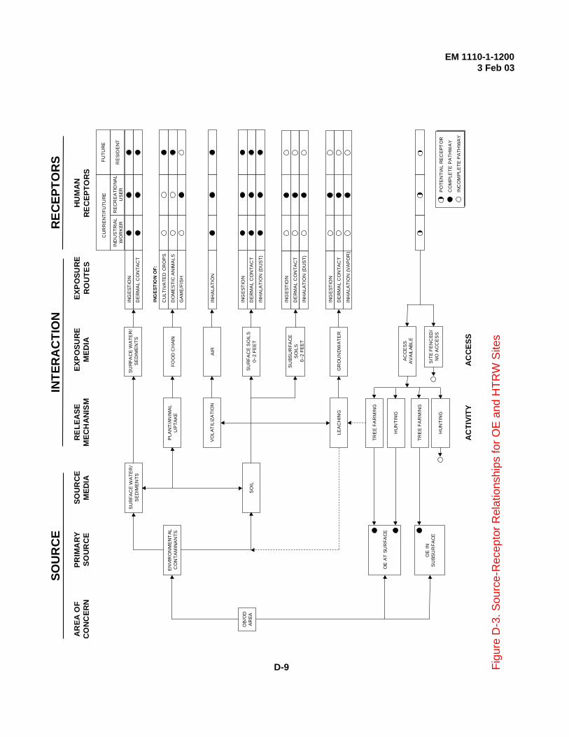
ING
EST
ION
DE
RM
AL
CO
NTA
CT
CU
LTIV
ATE
D C
RO
PS
DO
ME
STI
C A
NIM
ALS
GA
ME
/FIS
H
INH
ALA
TIO
N
ING
EST
ION
DE
RM
AL
CO
NTA
CT
INH
ALA
TIO
N (D
US
T)
ING
EST
ION
DE
RM
AL
CO
NTA
CT
INH
ALA
TIO
N (D
US
T)
ING
EST
ION
DE
RM
AL
CO
NTA
CT
INH
ALA
TIO
N (V
AP
OR
)
IND
US
TRIA
LW
OR
KER
CU
RR
EN
T/FU
TUR
E
RE
CR
EA
TIO
NA
LU
SER
FUTU
RE
RE
SID
EN
T
HUM
AN
REC
EPTO
RS
SU
RFA
CE
WA
TER
/S
ED
IME
NTS
SU
RFA
CE
WA
TER
/S
ED
IME
NTS
FOO
D C
HAI
NP
LAN
T/AN
IMA
LU
PTA
KE
AIR
VO
LAT
ILIZ
ATI
ON
SU
RFA
CE
SO
ILS
0–2
FEE
T
SU
BSU
RFA
CE
SO
ILS
0–2
FEE
T
GR
OU
ND
WA
TER
EXPO
SURE
RO
UTE
SEX
POSU
RE
MED
IARE
LEAS
EM
ECH
ANIS
MSO
UR
CE
MED
IAPR
IMA
RYSO
URC
EA
REA
OF
CONC
ERN
EN
VIR
ON
ME
NT
ALC
ON
TAM
INA
NTS
SO
IL
LEA
CH
ING
TRE
E F
AR
MIN
G
OE
AT
SUR
FAC
E
OB
/OD
AR
EA
ING
ESTI
ON
OF:
CO
MP
LETE
PA
THW
AY
INC
OM
PLE
TE P
ATH
WA
Y
SOU
RC
EIN
TER
AC
TIO
NR
ECEP
TOR
S
AC
CE
SS
AV
AIL
ABLE
SIT
E F
EN
CED
/N
O A
CC
ES
SP
OTE
NTI
AL
RE
CE
PTO
R
HU
NTI
NG
TRE
E F
AR
MIN
GO
E IN
SU
BSU
RFA
CE
HU
NTI
NG
ACC
ESS
ACTI
VITY
EM 1110-1-12003 Feb 03
D-9
Fi
gure
D-3
. Sou
rce-
Rec
epto
r Rel
atio
nshi
ps fo
r OE
and
HTR
W S
ites