conceptual design of solar powered airplanes for continuous flight
DESCRIPTION
not my workTRANSCRIPT
7/18/2019 Conceptual Design of Solar Powered Airplanes for Continuous Flight
http://slidepdf.com/reader/full/conceptual-design-of-solar-powered-airplanes-for-continuous-flight 1/18
Autonomous Systems Laboratory
Design of Solar Powered Airplanes for Continuous Flight
given in the framework of the ETHZ lecture“Aircraft and Spacecraft Systems: Design, Modeling and Control”
partially included in a forthcoming Springer book on“Advances in Unmanned Aerial Vehicles, State of the art and the road to autonomy”
A. Noth, R. Siegwart, W. Engel
Version 1.1
December 2007
Complete PhD Thesis of the author available at:http://www.sky-sailor.ethz.ch/docs/Thesis_Noth_2008.pdf

7/18/2019 Conceptual Design of Solar Powered Airplanes for Continuous Flight
http://slidepdf.com/reader/full/conceptual-design-of-solar-powered-airplanes-for-continuous-flight 2/18
Design of Solar Powered Airplanes for Continuous Flight December 2006
André Noth and Roland Siegwart 1
Sunrise II, 1975
1 Introduction
The achievement of a solar powered aircraft capable of continuous flight was still a dream
some years ago, but this great challenge has become feasible today. In fact, significant
progresses have been realized recently in the domains of flexible solar cells, high energy
density batteries, miniaturized MEMS and CMOS sensors, and powerful processors.
The concept is quite simple; equipped with solar cells covering its wing, it retrieves energy
from the sun in order to supply power to the propulsion system and the control electronics,
and charge the battery with the surplus of energy. During the night, the only energy availablecomes from the battery, which discharges slowly until the next morning when a new cycle
starts.
Nevertheless, major interdisciplinary effort is necessary to optimize and integrate concepts
and technologies to a fully functional system. As a matter of fact, the major issue is thecombination and sizing of the different parts in order to maximize a certain criterion, for
example the endurance, one parameter being the embedded payload.
In 2004, the Autonomous Systems Lab of EPFL/ETHZ launched the Sky-Sailor project under a contract with the European Space Agency. The objectives are the study and realization of asolar aircraft fully autonomous in navigation and power generation flying on Earth and thus
validate the feasibility of a Mars dedicated version.
This lecture presents the methodology used for the global design of solar powered airplanes
that are intended to achieve continuous flight on Earth. It was applied to the first prototype of Sky-Sailor but it is rather general so that it can be used as much for small airplane weighing
some hundreds of gram as for solar high altitude long endurance (HALE) platforms with a
wingspan of several tens of meters.
1.1 History of Solar Flight
Premises of solar aviation with model airplanes
On the 4th
of November 1974, the first flight of a solar- powered aircraft took place on the dry lake at Camp Irwin,
California. Sunrise I , designed by R.J. Boucher from AstroFlight Inc. under a contract with ARPA, flew 20 minutes at
an altitude of around 100 m during its inaugural flight. An
improved version, Sunrise II, was built and tested on the12
thof September 1975. The new cells, with a higher
efficiency of 14%, delivered a power of 600 W.
In Europe, the pioneers of solar model airplane were Helmut Bruss and Fred Militky. Onthe 16
thof August 1976, his model Solaris completed three flights of 150 seconds reaching
the altitude of 50 m [3].
Since this early time, many model airplane builders tried to fly with solar energy, this
hobby becoming more and more affordable. The endurance, limited to a few seconds at the
beginning, rapidly became minutes and then hours... [3]. Some people distinguished themselves like Dave Beck with Solar Solitude in 1996, Wolfgang Schaeper who set many

7/18/2019 Conceptual Design of Solar Powered Airplanes for Continuous Flight
http://slidepdf.com/reader/full/conceptual-design-of-solar-powered-airplanes-for-continuous-flight 3/18
Design of Solar Powered Airplanes for Continuous Flight December 2006
André Noth and Roland Siegwart 2
Gossamer Penguin, 1980
Helios, 1999-2003
records with Solar Excel in the 90’s and Sieghard Dienlin with his tiny solar model PicoSol
in 1998.
The dream of manned solar flight
After having flown solar model airplanes and proved that itwas feasible with sufficient illumination conditions, the new
challenge that fascinated the pioneers at the end of the 70’s
was solar manned flights.
The first models, Solar One of Fred To in GB and Solar Riser of Larry Mauro, used the concept was to charge a
battery on the ground using their solar panels and thenachieve short duration flights. The crucial stage consisting in
flying with the single energy of the sun without any storage
was reached by Dr. Paul B. MacCready and his company AeroVironment Inc in the US. Onthe 18
thof May 1980, the Gossamer Penguin realized what can be considered as the
world’s first piloted, solar-powered flight. On July 7, 1981, the next version named Solar
Challenger crossed the English Channel with solar energy as its sole power source.In Germany, Günter Rochelt built Solair I , a 16 m wingspan solar airplane thatincorporated a battery. On the 21
stof August 1983 he flew, mostly on solar energy and also
thermals, during 5 hours 41 minutes. In 1986, Eric Raymond started the design of the
Sunseeker in the US. At the end of 1989, it was test flown as a glider and during August1990, it crossed the United States in 21 solar-powered flights with 121 hours in the air.
In 1996, the Berblinger Contest took place in Ulm with the objective to develop a real,
practically usable solar aircraft that should be able to stay up with at least half the solar
energy a good summer day with clear sky can give. The team of Prof. Rudolf Voit- Nitschmann from Stuttgart University won the first prize with Icaré 2.
On the way to HALE (High Altitude Long Endurance) platforms and eternal flight
After the success of Solar Challenger , the US government
gave funding to AeroVironment Inc. to study the feasibility
of long duration, solar electric flight at high altitude. In1993, the Pathfinder , with its 30 m wingspan and 254 kg,
was tested at low altitude and became in 1994 part of
NASA’s Environmental Research Aircraft Sensor Technology (ERAST) program.
From 1994 to 2003, this program led to the construction of a
series of three successive solar aircrafts, Pathfinder Plus, Centurion and Helios. The latter
was intended to be the ultimate "eternal airplane”, incorporating energy storage for night-time flight. In 2001, Helios set an unofficial world record altitude of 29’524 m (96’863 ft)
but unfortunately, it never proved sustainable flight as it was destroyed when it fell into the
Pacific Ocean on June 26, 2003 due to structural failures.
In Europe, many projects were also conduced on HALE platforms. At the DLR Institute of Flight Systems, Solitair was developed within the scope of a study from 1994 to 1998 [23].
The Helinet project, funded by a European Program, ran between January 2000 and March

7/18/2019 Conceptual Design of Solar Powered Airplanes for Continuous Flight
http://slidepdf.com/reader/full/conceptual-design-of-solar-powered-airplanes-for-continuous-flight 4/18
Design of Solar Powered Airplanes for Continuous Flight December 2006
André Noth and Roland Siegwart 3
2003 with the target to study the feasibility of a solar-powered HALE platform for
broadband communications and Earth observation.
QinetiQ, a British company, is also very active in the field of solar HALE platforms with Zephyr , an airplane which flew in July 2006 for 18 hours, including 7 hours of flying in the
dark. It has recently been selected as the base platform for the Flemish HALE UAV remote
sensing system Mercator in the framework of the Pegasus project. The platform should fulfill missions like forest fire monitoring, urban mapping, coastal monitoring, etc.
But the objective of Helios to prove the feasibility of eternal flight for an unmanned
airplane was reached on the 22nd
of April 2005. Alan Cocconi, president and founder of AcPropulsion, flew his Solong during 24 hours and 11 minutes using only solar energy
coming from its solar panels and also thermals, currents of warm air rising from the desert
floor. The 4.75 m wingspan and 11.5 kg airplane confirmed its capabilities two monthslater on the 3
rd of June with a flight lasting 48 hours and 16 minutes.
The next dream to prove continuous flight with a pilot on board will perhaps come true
with Solar-Impulse, a 80 m wingspan lightweight solar airplane built in Switzerland. After
the manufacturing of a 60 m prototype in 2007-2008 and the final airplane in 2009-2010, around-the-world flight should happen in May 2011 with a stopover on each continent.
1.2 Brief description of the principle
Solar panels, composed by solar cells connected in a certain configuration, cover a certain
surface of wing or other part of the airplane (tail, fuselage,…). During the day, depending
on the sun irradiance and the inclination of the rays, the convert light into electrical energy.
A converter, called Maximum Power Point Tracker, ensures that the maximum amount of power is obtained from the solar panels. This power is used firstly to power the propulsion
group and the onboard electronics, and secondly to charge the battery with surplus of
energy.
Fig. 1 Schematic representation of power transfer
During the night, as no more power comes from the solar panels, only the battery supplies
the various elements. This is schematically represented on the figure below.
2 Conceptual Design Methodology
Aircraft design is the name given to the activities that span the creation on paper of a new
flight vehicle. The design process is usually divided into three phases or levels of design
[Leland]: Conceptual DesignÎ Preliminary DesignÎ Detail Design.

7/18/2019 Conceptual Design of Solar Powered Airplanes for Continuous Flight
http://slidepdf.com/reader/full/conceptual-design-of-solar-powered-airplanes-for-continuous-flight 5/18
Design of Solar Powered Airplanes for Continuous Flight December 2006
André Noth and Roland Siegwart 4
This methodology will only focus on conceptual design where the general configuration and
size is determined. Parametric trade studies are conducted using preliminary estimates of
aerodynamics and weight to converge on the best final configuration. The feasibility of thedesign to accomplish a given mission is established but the details of the configuration are
not defined.
One will also consider only level flight. Whether it is intended to achieve surveillance at lowaltitude or serve as a high altitude communication platform, a solar aircraft capable of continuous flight needs to fly at constant altitude. In fact, the first one would be useless for
ground surveillance at high altitude and the second one wouldn’t cover a sufficient area atlow altitude.
In this case, the energy and mass balances are the starting point of the design. In fact, the
energy collected during the day by the solar panels has to be sufficient to power the motor,the onboard electronics and also charge the battery that provides enough power to fly from
dusk to the next morning when a new cycle starts. Likewise, the lift force has to balance
exactly the airplane weight so that the altitude is maintained.
This leads finally to an hen and egg problem: the required power consumption allowsdimensioning the various parts, like motor, solar cells, battery, etc. but at the same time these
parts determine the airplane gross weight used for the calculation of the required power.
These relations are described in this section.
2.1 Irradiance model
A good model of irradiance depending on variables such as geographic position, time, solar
panels orientation and albedo was developed based on [7]. For our need here, this modelwas simplified for flat surfaces by a sinusoid as shown on Fig. 2.
0 2 4 6 8 10 12 14 16 18 20 22 240
200
400
600
800
1000
Time [hours]
I r r a d i a n c e [ W / m 2 ]
Exact model
(Duffie & Beckman)Sinusoidal model
I max
T day
Fig. 2 Approximation of irradiance with a sinusoid (Lausanne, June 21)
The maximum irradiance I max and the duration of the day T day, which are depending on thelocation and the date, allows to compute the daily energy per square meter as depicted in
Eq. 1. In order to take into account cloudy days, a constant is added with a value between 1(clear sky) and 0 (dark). This constitutes a margin for the calculation.
max
/ 2π =
day
day density solmargin
I T E k (1)

7/18/2019 Conceptual Design of Solar Powered Airplanes for Continuous Flight
http://slidepdf.com/reader/full/conceptual-design-of-solar-powered-airplanes-for-continuous-flight 6/18
Design of Solar Powered Airplanes for Continuous Flight December 2006
André Noth and Roland Siegwart 5
2.2 Power balance for level flight
The forces acting on the airplane during level flight are the lift L and the drag D defined as:
2 2
2 2
ρ ρ = = L D L C SV D C SV (2)
where C L and C D are respectively the lift and drag coefficients, ρ the air density, S the wingarea and V the airplane relative speed which is similar to the ground speed if one assume no
wind. C L and C D heavily depend on the airfoil, the angle of attack α, the Re number and Mach number. The drag coefficient is the sum of the airfoil drag C Da, the parasitic drag of
non-lifting parts that will be neglected here and the induced drag C Di than can be estimated
by:
2
π =
i
L D
C C
e AR(3)
where e is the Oswald’s efficiency factor and AR the aspect ratio of the wing, the ratio
between the wingspan and the chord. From Eq. 2 one can find the power for level flight
( )3
32
2
ρ = D
level
L
m g C P
S C (4)
Using the relation between S , b and AR, one can rewrite:
3
3 2
32
2
ρ = D
level
L
C AR g m P
bC (5)
Then, to obtain the total power consumption, efficiencies of the motor, its electronic
controller, the gearbox and the propeller have to be taken into account, as well as the power consumption of the control and navigation system and the payload instruments. In order to
lighten the reading, these relations will not be written here but further illustrated on Fig. 7.
2.3 Mass estimation models
For each part on the airplane, a good mass model is necessary in order to calculate the total
mass m and use it in Eq. 5. The simple models will not be expressed in equation but onlyshortly described as they will be further illustrated in Fig. 7.
The mass of the control and navigation system is considered as fixed, just like the payload
that is a requirement defined at the beginning. Concerning the battery, its mass is directly
proportional to the energy it needs to store, which is the product between power consumption and night duration, and inversely proportional to its energy density.
In the case of the solar panels, one can find the area they cover by putting into equality the
total electric energy consumed each day with the total electric energy obtained from the
sun.
max
/2night day
elec tot day solmargin solar cells mppt
chrg dischrg
T I TP T k A η η
η η π
⎛ ⎞+ =⎜ ⎟⎜ ⎟
⎝ ⎠(6)

7/18/2019 Conceptual Design of Solar Powered Airplanes for Continuous Flight
http://slidepdf.com/reader/full/conceptual-design-of-solar-powered-airplanes-for-continuous-flight 7/18
Design of Solar Powered Airplanes for Continuous Flight December 2006
André Noth and Roland Siegwart 6
The obtained area A solar is then used to calculate the mass of the solar panels, taking into
account the mass of the cells themselves and their encapsulation made of nonreflectivesheets of polymer.
A special electronic device, called Maximum Power Point Tracker (MPPT) is required to
adapt the voltage of the solar panels so that they provide the highest power possible. Its
mass is proportional to the maximum power it has to convert, which can be calculated using the solar panels area calculated above as showed in equation Eq. 7. The constant k mppt
was found based on a study of existing high efficiency products (Fig. 3).
maxmppt mppt solmax mppt cells mppt solar m k P k I Aη η = = (7)
0 0.5 1 1.5 2 2.50
500
1000
1500
2000
2500
3000
3500
4000
4500
5000
5500
Mass [Kg]
M a x
P o w e r
[ W ] Max Power = 2368 Mass
Mppt products
Fitting curve
Sky-Sailor Sommerauer AcPropulsion SolongBiel MPPTBrusa Elektronik MPT-N15Icaré 2
Mass [g]
7.5545
100650
11502058
Power [W]
30100300
120026005046
Eff [%]
979898999998
Fig. 3. Power density of high efficiency MPPTs
The mass of all the electric cables, especially those connecting the solar panels to the
MPPT, can be modeled according to the airplane wingspan and the electrical current.
However, in order to avoid a too complex model, this mass is included in the onboard
electronics.
Concerning the propulsion group, composed of the motor, the gearbox and the propeller,
[8] and [9] proposed a model, adapted from civil aircraft to solar airplane, which takes into
account the number of blades, the propeller diameter and the power of the motor. Somecalculations show that the estimation is far too optimistic for model aircraft. [18] and [25]
propose very similar models exclusively based on power, where the mass of the propulsion
group is estimated as
0.0045prop prop
m P= (8)
For real large scale solar airplanes like Helios, Icaré 2 or Solair II , this factor is
respectively 0.0033, 0.0012 and 0.0008 kg/W whereas the first experiments with Sky-Sailor showed a factor of around 0.010 kg/W. The reason is that for an airplane taking off on a
runway, the difference between start power and mean power for level flight is low. At theopposite, in the case of a hand launched model airplane that needs to increase its speed and
take altitude rapidly, the start power is far higher than the mean power required for level
flight. Thus, the motor has to be oversized and its mass increases.

7/18/2019 Conceptual Design of Solar Powered Airplanes for Continuous Flight
http://slidepdf.com/reader/full/conceptual-design-of-solar-powered-airplanes-for-continuous-flight 8/18
Design of Solar Powered Airplanes for Continuous Flight December 2006
André Noth and Roland Siegwart 7
Finally, the mass of the airplane structure is the most difficult part to model and the two
main approaches mainly used in the literacy for solar airplanes appear inadequate. That isthe reason why we will study this part more in details and propose a new model
The first approach from D.W. Hall [8] consists in calculating separately the mass of all the
elements constituting the airframe, i.e the spar, the leading and trailing edge, covering, ribs,
control surfaces, fuselage and tail as functions of the total mass, aspect ratio and wing area.It was applied by [6] on airplane with more than 60 m wingspan but shows to be
inapplicable for model airplane. The second approach, proposed by W. Stender in 1969
[20], is based on statistical data for sailplanes with twin boom tails. The entire airframeweight is estimated parametrically as a function of aspect ratio, surface and number of
boom tails.
0.311 0.778 0.4678.763af W n S AR= (9)
This simple model was adopted by [17], [18] and [25] for their solar airplane design. In
order to verify this model, a database containing wingspan, wing area, aspect ratio,structure weight and gross weight of 415 sailplanes of various dimensions was created.
They are divided into 92 radio controlled unmanned models and 323 manned sailplanes.
The weight of these samples is represented on Fig. 4 as function of the wing area and the
aspect ratio. Eq. 9 is obviously very optimistic for large scale sailplanes and too pessimisticfor model airplane. Thus, using a least-square fitting method, we propose a new equation
based on the sailplane database described above.
1.59 0.715.58af W S AR= (10)
Using the definition of aspect ratio, it can of course also be expressed as a function of
wingspan:
3.18 0.885.58af W b AR−= ⋅ ⋅ (11)
10-1
100
101
102
100
101
102
103
104
Wing area [m2
]
W e
i g h t
[ N ]
5
10
15
20
25
30
35
40
Proposed equation
W = 5.58 S1.59
AR0.71
Stenders equation
W = 8.763 S0.778
AR0.467
AR
Fig. 4 Comparison of two airframe mass models with real data

7/18/2019 Conceptual Design of Solar Powered Airplanes for Continuous Flight
http://slidepdf.com/reader/full/conceptual-design-of-solar-powered-airplanes-for-continuous-flight 9/18
Design of Solar Powered Airplanes for Continuous Flight December 2006
André Noth and Roland Siegwart 8
But these equations only give the mean tendency of all the 415 records, in which the
construction quality of airplane varies. As we are interested in having a model of thehighest quality sailplanes only, we propose to separate the records in two groups, the one
that have a lower weight than it would have been estimated by the interpolation and the
others. Keeping only the first group and applying one more time the curve fitting process,
we obtain after five iterations an equation that models the 5% best sailplanes1.55 1.30.44
af W S AR= (12)
Here again, one can rewrite Eq. 12 using wingspan instead of surface
3.1 0.250.44af W b AR−= ⋅ ⋅ (13)
It is interesting to see the evolution of the constant and the two exponents during theiterations when construction quality increases. The wing area is always related to the
weight with a power of around 1.55 to 1.59, this exponent doesn’t change significantly. At
the opposite, the influence of the aspect ratio increases with the quality.
Several scientists studied the correlations between gross weight, wingspan, wing area and speed more generally including all the commercial flying machines, from the hang glider to
the big airliners, and also in the animal kingdom, from the flies to the albatross. Above this
amount of work, [19] offers an excellent and concise review of all these correlations.
One of the best contributors in this field is Henk Tennekes who presented very interestingcorrelations that he summarized in a log-log diagram named “The great flight diagram”
[22]. The result is impressive: from the common fruit fly to the Boeing 747, all points
follow approximately a line corresponding to Eq. 14.
1/3/ 47W S W= ⋅ (14)
The concept of geometric similarity is the base of this equation; if one assumes geometric
similarity among flying objects, the weight W is proportional to the cube of a characteristiclength l, the surface S to the square and consequently the wing loading is linear with l and thus with W1/3. It is interesting to notice that if we transform Eq. 12 that represents our
model in the form above, the weight is linked to the wing loading with an exponent of 0.35
which is close to the model proposed by Tennekes.
0.35 0.840.59af af
W S W AR= ⋅ ⋅ (15)
Fig. 5 presents, superposed on the great flight diagram, the position of the 415 sailplanes aswell as the mean and the top 5% model developed above. A model from B.W. McCormick
[12] for the estimation of the wing loading of manned airplanes, also based on square-
cubing scaling laws, is also represented. One remarkable point is its asymptote at a weight
of 1000 N which corresponds to the weight of a single human person in an incrediblylightweight airplane. The airplane approaching the most this asymptote is the Gossamer
Albatross, the human powered aircraft built by Dr. Mcready that crossed the English
Channel in 1979.
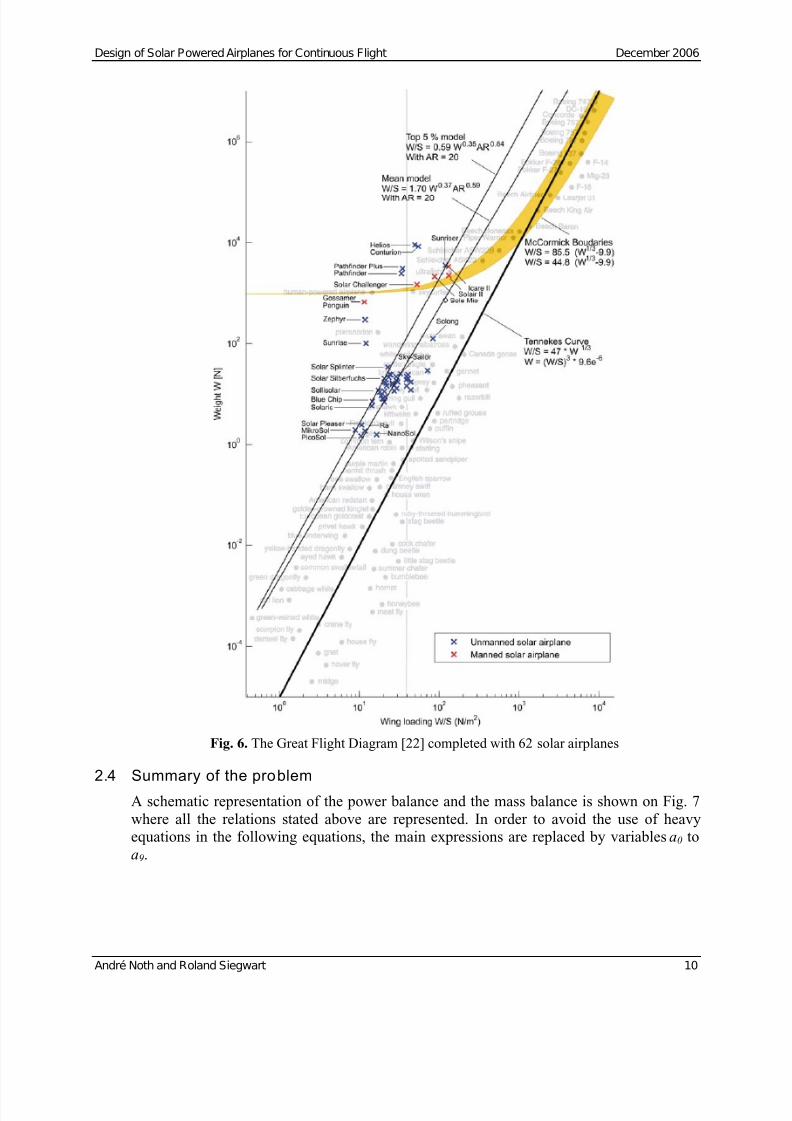
Sixty-two of the most famous solar airplanes flown to date, from RC models to HALE
platforms, are represented in the same way on Fig. 6. One can observe that whereas the
small scale models are located in the same region than the non-solar one, the large scale
solar airplanes are far away from the model we developed.

7/18/2019 Conceptual Design of Solar Powered Airplanes for Continuous Flight
http://slidepdf.com/reader/full/conceptual-design-of-solar-powered-airplanes-for-continuous-flight 10/18
Design of Solar Powered Airplanes for Continuous Flight December 2006
André Noth and Roland Siegwart 9
The reason is that Helios, Centurion, Pathfinder, Pathfinder Plus and Zephyr have a major
difference in their configuration compared to all other models; in fact, their wingextremities are supported by several wheels, when not in flight. The flexion constraints on
the wing are reduced which allows using a lighter construction method. These big models
have impressive low weight but the direct consequence is their incredible fragility. That
was the cause of Helios crash in 2003. The five manned solar airplanes are slightly aboveMcCormick upper boundary, except Gossamer Penguin, the solar version of human
powered Gossamer Albatross.
Fig. 5. The Great Flight Diagram [22] completed with 415 sailplanes
7/18/2019 Conceptual Design of Solar Powered Airplanes for Continuous Flight
http://slidepdf.com/reader/full/conceptual-design-of-solar-powered-airplanes-for-continuous-flight 11/18
Design of Solar Powered Airplanes for Continuous Flight December 2006
André Noth and Roland Siegwart 10
Fig. 6. The Great Flight Diagram [22] completed with 62 solar airplanes
2.4 Summary of the problem
A schematic representation of the power balance and the mass balance is shown on Fig. 7
where all the relations stated above are represented. In order to avoid the use of heavyequations in the following equations, the main expressions are replaced by variables a0 to
a9.

7/18/2019 Conceptual Design of Solar Powered Airplanes for Continuous Flight
http://slidepdf.com/reader/full/conceptual-design-of-solar-powered-airplanes-for-continuous-flight 12/18
Design of Solar Powered Airplanes for Continuous Flight December 2006
André Noth and Roland Siegwart 11
Fig. 7. Schematic representation of the design methodology
We are now able to solve this cyclic problem by using all these relations
ctrl payload struct solar batt mppt propm m m m m m m m= + + + + + + (16)
( )( ) ( )( ) 1
10 11
3
21 x
0 1 7 8 9 5 6 2 7 9 5 6 3 4
a a
m a a a a a a a m a a a a a a a bb
− + + + = + + + +
(17)
Reducing one more time the complexity of the equation by using substitution variables, one
obtains.
N
1
1312
3
210 11 4
1 x
aa
m a m a a b
b
− = +
(18)
It can be shown that Eq. 19 has only a positive non-complex solution for m, which makes
physically sense, if
212 13
4
27a a ≤ (19)
For a given airplane configuration, the feasibility is proved if this inequality is respected
and at the same time if the surface of solar cells is smaller than the wing area.
In order to be able to extract meaningful information, it is necessary, among the thirty
parameters that our model contains, to distinguish between three different classes:
1. The first group is composed of the parameters which are linked to a technologyand are constant or can be regarded as constant for very good design. This is for
example the case of motor or propeller efficiencies that should be around 85 %when optimized for a special application.
2. The second group of parameters is linked to the type of mission; they concern
flight altitude, date and payload.
7/18/2019 Conceptual Design of Solar Powered Airplanes for Continuous Flight
http://slidepdf.com/reader/full/conceptual-design-of-solar-powered-airplanes-for-continuous-flight 13/18
Design of Solar Powered Airplanes for Continuous Flight December 2006
André Noth and Roland Siegwart 12
3. Finally, the last group is composed of the parameters that we vary during the
optimization process in order to determine the airplane layout, that is why oneshould use here the term variable that parameter. They are for example the
wingspan or the aspect ratio.
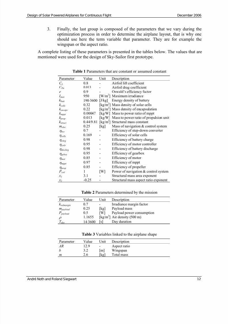
A complete listing of these parameters is presented in the tables below. The values that are
mentioned were used for the design of Sky-Sailor first prototype.
Table 1 Parameters that are constant or assumed constant
Parameter Value Unit Description
C L 0.8 - Airfoil lift coefficientC Da 0.013 - Airfoil drag coefficient
e 0.9 - Oswald’s efficiency factor
I max 950 [W/m2] Maximum irradiancek batt 190⋅3600 [J/kg] Energy density of battery
k cells 0.32 [kg/m2] Mass density of solar cells
k encaps 0.22 [kg/m2] Mass density of encapsulation
k mppt 0.00047 [kg/W] Mass to power ratio of mpptk prop 0.013 [kg/W] Mass to power ratio of propulsion unit
k struct 0.44/9.81 [kg/m3] Structural mass constant
melec 0.25 [kg] Mass of navigation & control system
η bec 0.7 - Efficiency of step-down converter
η cells 0.169 - Efficiency of solar cells
η chrg 0.98 - Efficiency of battery charge
η ctrlr 0.95 - Efficiency of motor controller
η dischrg 0.98 - Efficiency of battery discharge
η grbox 0.95 - Efficiency of gearbox
η mot 0.85 - Efficiency of motor
η mppt 0.97 - Efficiency of mppt
η prop 0.85 - Efficiency of propeller
P ctrl 1 [W] Power of navigation & control system x1 3.1 - Structural mass area exponent
x2 -0.25 - Structural mass aspect ratio exponent
Table 2 Parameters determined by the mission
Parameter Value Unit Description
k solmargin 0.7 - Irradiance margin factor m payload 0.25 [kg] Payload mass
P payload 0.5 [W] Payload power consumption
ρ 1.1655 [kg/m3] Air density (500 m)
T day 14⋅3600 [s] Day duration
Table 3 Variables linked to the airplane shape
Parameter Value Unit Description
AR 12.9 - Aspect ratio
b 3.2 [m] Wingspan
m 2.6 [kg] Total mass

7/18/2019 Conceptual Design of Solar Powered Airplanes for Continuous Flight
http://slidepdf.com/reader/full/conceptual-design-of-solar-powered-airplanes-for-continuous-flight 14/18
Design of Solar Powered Airplanes for Continuous Flight December 2006
André Noth and Roland Siegwart 13
3 Application of the methodology
Having the mission requirements, the method explained here above can be applied in order toevaluate the possible shapes of a solar airplane. This will be illustrated with the example of
the Sky-Sailor prototype. The objective here is to embed a 250 g payload consuming 0.5 W
and fly continuously at low altitude during two months in summer. These mission parameters
allow plotting the relations between the main variables, i.e. wingspan and aspect ratio, and the flight characteristics for all the possible configurations.
Fig. 8. Design plots of a solar airplane with a payload of 250 g
This is done on Fig. 8 where one can first observe that the minimum airplane wingspan isaround 2.5 m and that keeping the same construction quality the airframe will become too
heavy from a certain point and make continuous flight impossible. This means that for larger airplanes, the quality of the wing structure in terms of weight becomes more and more
important. In the range of ten to twenty meters wingspan, which corresponds to commercial
sailplanes, the construction method used today should be massively improved to see one daya model in this range fly continuously.
In our case, among the many possible configurations, the final choice will be guided by
considerations on the flight speed, size or even production costs that can be estimated
knowing the prices of the different elements.
It is also interesting to have a look on mass distribution. Fig 9 shows that the half of theweight is only due to the battery and that the structure constitutes also an important part that
increases with wingspan as said before. This knowledge allows putting efforts on the critical
parts instead of working on elements that play a minor role in overall mass.

7/18/2019 Conceptual Design of Solar Powered Airplanes for Continuous Flight
http://slidepdf.com/reader/full/conceptual-design-of-solar-powered-airplanes-for-continuous-flight 15/18
Design of Solar Powered Airplanes for Continuous Flight December 2006
André Noth and Roland Siegwart 14
Fig. 9. Mass distribution with respect to wingspan assuming AR = 12
3.1 Influence of Technologies on the feasibili ty
By changing the value of parameters belonging to the first group of parameters listed inTable 1, one can evaluate what is the effect of technological changes or improvements. For example, concerning the choice of solar cells, one can compare the use of lightweight cells
with low efficiency compared to heavier ones that are two times more efficient.
With the results that the methodology gives in the case of Sky-Sailor as explained in the
previous chapter, one can see that the two major contributors in terms of weight are the battery and the wing structure. That is the reason why one will focus here on the two parts
and observe the influence of the technology adopted.
Considerations about battery technology
Today, the highest energy ratio for rechargeable battery is around 200 Wh/kg for Lithium
Polymer technology. But one can expect in some years an import increase of this value.The miniaturization of fuel cells will also make them suitable for small solar UAVs.
0 2000 4000 6000 8000 10000 120000
1
2
3
4
5
6
7
8
9
10
Maximum altitude of flight [m]
W i n g s p a n
[ m ]
200
240
280
320
360
400
k [Wh]batt
Fig. 10. Impact of the battery capacity on the flight altitude

7/18/2019 Conceptual Design of Solar Powered Airplanes for Continuous Flight
http://slidepdf.com/reader/full/conceptual-design-of-solar-powered-airplanes-for-continuous-flight 16/18
Design of Solar Powered Airplanes for Continuous Flight December 2006
André Noth and Roland Siegwart 15
Fig. 10 shows that in the case of Sky-Sailor, doubling the capacity of the energy storage
system would make continuous flight at 10’000 m altitude possible.
Considerations about airplane structure
The application we saw with a payload of 0.5 kg showed us that continuous flight is
possible for wingspan from 2.5 m to 5 m. Even in the scenario where no extra payload is
embedded, these two limits exist. The reason is that using our cubic structural weight
scaling law, the empty airframe becomes too heavy for high dimension. Hence, one canwonder what shape should this structural weight scaling law have to make continuous flight
possible with all wingspan.
This is done, using our methodology, by setting k struct to zero which means that we consider
an ideal wing structure that has no mass. Then, try to know for a specified b and AR what
the maximum payload weight that can be embedded is. Hence, this value will also be the
maximum weight that the wing can have if we assume no payload. Starting with Eq. 19, wehave:
( )( )( )2
10 2 7 9 5 6 3 2
1 4
27a a a a a a a b+ + + ≤ (20)
Then, isolating a3 which corresponds to the payload mass, we have:
( )( )23 2 7 9 5 62
10
4
27a b a a a a a
a≤ − + + (21)
( )( )2 7 9 5 6210
4
27payload
ARm S a a a a a
a≤ − + + (22)
One can then express the maximum admissible wing structure mass depending on its
surface as depicted on Fig. 11.
Fig. 11. Maximum admissible structure mass depending on wing surface for AR = 15
It is interesting to see that the relation is linear, which means that the ratio between massand surface has to remain under a certain value. When plotting this relation on the Fig. 6, it
proves clearly as it was said before that the realization of a solar airplane flying
continuously is more difficult for higher wingspan. In fact, the top 5% model we identified has a surface density that increases whereas it should stay constant to guaranty feasibility.

7/18/2019 Conceptual Design of Solar Powered Airplanes for Continuous Flight
http://slidepdf.com/reader/full/conceptual-design-of-solar-powered-airplanes-for-continuous-flight 17/18
Design of Solar Powered Airplanes for Continuous Flight December 2006
André Noth and Roland Siegwart 16
Fig. 12. Maximum admissible wing surface density
4 Conclusion
This lecture presented the global methodology that was developed for the design of the Sky-Sailor solar airplane. It was applied on our first prototype and revealed to be very useful,
efficient and accurate [26]. The great benefit is that it is general enough to be applied to a
wide range of size, from small model airplane to large scale high altitude platforms.Moreover, the analytical form of the method allows identifying clearly some general
principles, like the constancy of wing surface density, the designer should be aware of.
Hence, it was proved here that the realization of such airplane is more difficult for higher
dimension. Of course, after this conceptual design phase, the next step is to achieve the preliminary design where the design of all the parts is approached more into details.
AR =15AR =20AR =25
7/18/2019 Conceptual Design of Solar Powered Airplanes for Continuous Flight
http://slidepdf.com/reader/full/conceptual-design-of-solar-powered-airplanes-for-continuous-flight 18/18
Design of Solar Powered Airplanes for Continuous Flight December 2006
André Noth and Roland Siegwart 17
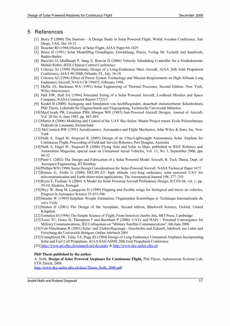
5 References
[1] Berry P (2000) The Sunriser - A Design Study in Solar Powered Flight, World Aviation Conference, San
Diego, USA, Oct 10-12
[2] Boucher RJ (1984) History of Solar Flight, AIAA Paper 84-1429
[3] Bruss H (1991) Solar Modellflug Grundlagen, Enwicklung, Praxis, Verlag für Technik und handwerk,
Baden-Baden[4] Buccieri D, Mullhaupt P, Jiang Z, Bonvin D (2006) Velocity Scheduling Controller for a Nonholonomic
Mobile Robot, IEEE Chinese Control Conference
[5] Colozza AJ (1990) Preliminary Design of a Long-Endurance Mars Aircraft, AIAA 26th Joint PropulsionConference, AIAA 90-2000, Orlando, FL, July 16-18
[6] Colozza AJ (1994) Effect of Power System Technology and Mission Requirements on High Altitude Long
Endurance Aircraft, NASA CR 194455, February 1994.
[7] Duffie JA, Beckman WA (1991) Solar Engineering of Thermal Processes, Second Edition. New York,Wiley-Interscience
[8] Hall DW, Hall SA (1984) Structural Sizing of a Solar Powered Aircraft, Lockheed Missiles and Space
Company, NASA Contractor Report 172313
[9] Keidel B (2000) Auslegung und Simulation von hochfliegenden, dauerhaft stationierbaren Solardrohnen,PhD Thesis, Lehrstuhl für Flugmechanik und Flugregelung, Technische Universität München
[10] MacCready PB, Lissaman PBS, Morgan WR (1983) Sun-Powered Aircraft Designs, Journal of Aircraft,Vol. 20 No. 6, June 1983. pp. 487-493[11] Mattio A (2006) Modeling and Control of the UAV Sky-Sailor, Master Project report, Ecole Polytechnique
Fédérale de Lausanne, Switzerland
[12] McCormick BW (1995) Aerodynamics, Aeronautics and Flight Mechanics, John Wiley & Sons, Inc. New
York [13] Noth A, Engel W, Siegwart R (2005) Design of an Ultra-Lightweight Autonomous Solar Airplane for
Continuous Flight, Proceeding of Field and Service Robotics, Port Douglas, Australia
[14] Noth A, Engel W, Siegwart R (2006) Flying Solo and Solar to Mars, published in IEEE Robotics and
Automation Magazine, special issue on Unmanned Aerial Vehicles, Vol. 13, No. 3, September 2006, pps
44-52[15] Patel C (2002) The Design and Fabrication of a Solar Powered Model Aircraft, B. Tech Thesis, Dept. of
Aerospace Engineering, IIT Bombay[16] Phillips WH (1980) Some Design Considerations for Solar-Powered Aircraft. NASA Technical Paper 1675
[17] Romeo G, Frulla G (2004) HELIPLAT: high altitude very-long endurance solar powered UAV for telecommunication and Earth observation applications, The Aeronautical Journal 108, 277–293
[18] Rizzo E, Frediani A (2004) A Model for Solar Powered Aircraft Preliminary Design, ICCES 04, vol. 1, pp.
39-54, Madeira, Portugal[19] Shyy W, Berg M, Ljungqvist D (1999) Flapping and flexible wings for biological and micro air vehicles,
Progress in Aerospace Science 35:455-506
[20] Stender W (1969) Sailplane Weight Estimation, Organisation Scientifique et Technique Internationale du
vol a Voile[21] Stinton D (2001) The Design of the Aeroplane, Second edition, Blackwell Science, Oxford, United
Kingdom
[22] Tennekes H (1996) The Simple Science of Flight, From Insects to Jumbo Jets, MIT Press, Cambridge[23] Tozer TC, Grace D, Thompson J and Baynham P (2000) UAVs and HAPs - Potential Convergence for
Military Communications, IEE Colloquium on "Military Satellite Communications", 6th June 2000
[24] Voit-Nitschmann R (2001) Solar- und Elektroflugzeuge - Geschichte und Zukunft, Jahrbuch aus Lehre und Forschung der Universität Stuttgart, Online Jahrbuch 2001
[25] Youngblood JW, Talay TA, Pegg RJ (1984) Design of Long-Endurance Unmanned Airplanes IncorporatingSolar and Fuel Cell Propulsion, AIAA/SAE/ASME 20th Joint Propulsion Conference
[26] http://www.asl.ethz.ch/research/asl/skysailor & http://www.sky-sailor.ethz.ch
PhD Thesis published by the author
A. Noth, Design of Solar Powered Airplanes for Continuous Flight, Phd Thesis, Autonomous Systems Lab,ETH Zürich, 2008
http://www.sky-sailor.ethz.ch/docs/Thesis_Noth_2008.pdf