conceptual design of blended wing body business … kones 2013 no 4 vol 20... · journal of kones...
TRANSCRIPT

Journal of KONES Powertrain and Transport, Vol. 20, No. 4 2013
CONCEPTUAL DESIGN OF BLENDED WING BODY BUSINESS JET AIRCRAFT
Taufiq Mulyanto, M. Luthfi Imam Nurhakim
Institut Teknologi Bandung
Faculty of Mechanical and Aerospace Engineering Jl. Ganesa 10, Bandung, Indonesia
tel.: +62 22 2504243, fax: +62 22 2534099 e-mail: [email protected]
Abstract
Blended Wing Body concept offers several advantages compared to traditional aircraft tube and wing concept. The advantages mainly come from the distributed aerodynamic and structural loads, which leads to better aerodynamic performance as well as lighter structural weight. Most of the existing studies were focused on big transport aircraft carrying 400 to 800 passenger. In this study, a conceptual design of a business jet aircraft applying blended wing body concept is carried out. The market forecast for this category of aircraft can reach up to 24000 aircraft in the next 20 years. The possibility of having larger cross section is one of the competitive advantages, notably in a long-range flight. The requirement stated was to fly a trans-atlantic flight and carrying up to 18 passengers. It has to have a low floor height permitting easy passenger access. The design process consists of initial weight estimation, initial sizing, and preliminary aerodynamics, weight and balance and performance analysis. Some design consideration specially related with Blended Wing Body concept will be discussed, i.e. take-off and landing aerodynamics, structural concept, stability and control. The final design resulted in twin-engine aircraft, a Maximum Take-off Weight of 44 ton, cabin floor area of 6.9 x 10 m, winglet and split rudder for directional stability and control, and elevons for longitudinal and lateral control.
Keywords: transport, business jet aircraft, blended wing body, conceptual design 1. Introduction 1.1. Blended Wing Body configuration
Blended Wing Body (BWB) or sometimes referred, as Hybrid Wing Body is a type of aircraft configuration, which has an airfoil shaped body contributing to overall lift during its flight. It has visibly separate wing structure, which is smoothly blended into the body. The airfoil shaped body acts as fuselage structure in the conventional aircraft configuration, which generally host payload. BWB configuration is different to flying wing configuration, sometimes also called tailless or all-wing configuration. On flying wing configuration, like Horten Ho-1 and YB49 (Fig. 1), the aircraft body is completely immersed in the wing structure. Either BWB and flying wing configuration has no horizontal tail plane or canard to stabilize and control the aircraft. They may have vertical aerodynamic surface located at the rear body or at the wing tip.
Concept of flying wing was developed and experimented in 1930s. Some flight had been successfully made by Horten brothers in Germany (Fig. 1a), Northrop in USA and Ito Aircraft Laboratory in Japan [5]. In 1941 and 1949, Northrop corporation built and flew XB35 and YB49 (Fig. 1b). The only significant flying wing aircraft entering production was bomber B-2 Spirit (Fig. 1c), which was first flown in 1989. The main advantage of such a configuration is a better aerodynamic efficiency compared to conventional configuration. The absence of the fuselage reduces considerably the aircraft wetted area; hence drag. It also permits a better span wise lift distribution, resulting in a reduction of lift-induced drag. Moreover, a more evenly load distribution permits a better structural efficiency as well.

T. Mulyanto, M. L. I. Nurhakim
a)
b)
c)
d)
Fig. 1. Flying wings and BWB aircrafts: Horten Ho-1 (a), Northrop YB-49 (b), Northrop B-2 Spirit (c), Boeing XB-48 (d)
An extensive study of BWB configuration was performed by McDonnell Douglas funded by NASA Langley Research Centre in 1988 [6]. The study was to develop and compare advanced technology of subsonic transports for a design mission range of 7000 nm and carrying 800 passengers at 0.85 Mach. The study resulted in a BWB aircraft configuration. A pivotal decision was to abandon the requirement for bearing pressure load in hoop tension as in the conventional tube and wing configuration. It thus assumes that an alternate efficient structure could be developed. A challenge that has been and still studied [8, 13].
Based on the result of the study, a Boeing preliminary design study of a BWB transport aircraft carrying 450 passenger was initiated [6]. Flight dynamic and aerodynamic experimental researches on BWB were performed since 1999 and culminated on a series of flight testing of 8.5% model X-48B (Fig. 1d) [14].
In Europe, a collaborative EU project on blended wing body configuration was launched in 2002 [2]. The project name was VELA, which stands for Very Efficient Large Aircraft. The project has studied several configurations of BWB aircraft, one of which was VELA-2 (Fig. 2).
Fig. 2. Boeing BWB-450 and EU Project VELA-2
300
Conceptual Design of Blended Wing Body Business Jet Aircraft
A comparative study of BWB configuration to conventional tube and wing configuration for a typical mission of 8700 nm an carrying approximately 480 passengers conclude that, BWB configuration has 19% less Operating empty Weight, 18% less Maximum Take-off weight, and 32% less fuel burn per seat [6]. 1.2. Niche for small BWB aircraft
Studies on BWB aircraft design were largely focus on high capacity aircraft ranging from 400 to 800 passengers, and eventually 200 pax [6]. A possible implementation of the concept on a much smaller aircraft, such as business aircraft, had not been studied widely. There has been some preliminary studies as in [4]. Business jet aircrafts are segmented in light, medium and large category defined through a combination of price, range and cabin volume (Tab. 1). Thus, aerodynamic efficiency in long distance flight and large cabin volume are some off key considerations for business aircraft.
The potential market of business jet in the incoming 2 decades was estimated to be promising. Bombardier forecasted 24000 new business jet aircrafts, worth 648 billion USD, would be required in 2012-2031 [1]. Different from large transport aircraft sale, the business jet delivery, especially for the large business jet category was less affected by global economic downturn [9].
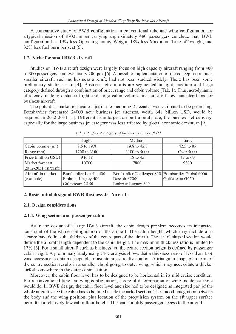
Tab. 1. Different category of Business Jet Aircraft [1]
Light Medium Large Cabin volume (m3) 8.5 to 19.8 19.8 to 42.5 42.5 to 85 Range (nm) 1700 to 3100 3100 to 5000 Over 5000 Price (million USD) 9 to 18 18 to 45 45 to 69 Market forecast 2012-2031 (aircraft)
10700 7800 5500
Aircraft in market (example)
Bombardier LearJet 400 Embraer Legacy 400 Gulfstream G150
Bombardier Challenger 850 Dassult F2000 Embraer Legacy 600
Bombardier Global 6000 Gulfstream G650
2. Basic initial design of BWB Business Jet Aircraft 2.1. Design considerations 2.1.1. Wing section and passenger cabin
As in the design of a large BWB aircraft, the cabin design problem becomes an integrated constraint of the whole configuration of the aircraft. The cabin height, which may include also a cargo bay, defines the thickness of the centre part of the aircraft. The airfoil shaped section would define the aircraft length dependent to the cabin height. The maximum thickness ratio is limited to 17% [6]. For a small aircraft such as business jet, the centre section height is defined by passenger cabin height. A preliminary study using CFD analysis shows that a thickness ratio of less than 15% was necessary to obtain acceptable transonic pressure distribution. A triangular shape plan form of the centre section results in a smaller chord going to outer wing, which may necessitate a thicker airfoil somewhere in the outer cabin section.
Moreover, the cabin floor level has to be designed to be horizontal in its mid cruise condition. For a conventional tube and wing configuration, a careful determination of wing incidence angle would do. In BWB design, the cabin floor level and size had to be designed as integrated part of the whole aircraft since the cabin has to be fitted inside the airfoil section. The smooth integration between the body and the wing position, plus location of the propulsion system on the aft upper surface permitted a relatively low cabin floor height. This can simplify passenger access to the aircraft.
301

T. Mulyanto, M. L. I. Nurhakim
2.1.2. Take-off and landing
Since there is no other control surface (normally located at tail or canard) to trim the resulting pitching moment, in BWB aircraft, trailing edge control surface cannot be used as flap to increase lift. This condition resulted that BWB design has a relatively lower maximum lift coefficient compared to conventional aircraft. A lower wing loading is necessary to provide comparable take-off and landing performance. Without the use of leading edge flap, a maximum lift coefficient would be around 0.85. With leading edge flap, this could be increase to around 1.7 [6]. The maximum lift coefficient will then occur at a higher angle of attack.
A study on using other high lift device system such as belly flaps located under wing has been studied [12]. The idea was to produce an increase of positive lift in front of the centre of gravity (cg) by deploying a small under wing flap, which is located close to the cg. Wind tunnel test and simulation results shows that the system may increase the total maximum lift coefficient up to 30%, hence shortening landing distance. 2.1.3. Transonic aerodynamic
Wave drag has been found to be a significant component of the total drag. It highlights the importance of a span loading distribution that minimise lift induced drag. Optimal span wise lift distribution should be a fine balance of vortex-induced drag and wave drag due to shock wave at transonic speed [10]. Obtaining an optimized pressure distribution may increase up to 3.0 higher CL/CD by reducing about 37% wave drag and 18.9% pressure drag [7].
Transonic study in wind tunnel showed anticipated reduction in pitching moment with increased Mach number, but followed with an unanticipated large pitching moment increase [3]. This might not be favourable in terms of flight control. 2.1.4. Flight dynamics
One of the challenges encountered in BWB configurations was related to short-coupled control, notably for pitch control, in which the lever arm from the control surface is significantly shorter than those in conventional configuration. This means that to produce same pitch up moment, a much greater down force is required, which could reduce significantly the aircraft total lift force. This characteristic is not desired, especially during take-off and landing phase.
Historically, flying wing configuration has been trimmed in pitching by sweeping the wing and downloading wingtips. It resulted in a non-elliptical lift distribution. To avoid downloading wingtips, negative static margin might be necessary. However, it would necessitate an active flight control system, which would consume a large amount of power, since a significant aerodynamic force had to be generated to pitch the aircraft due to short lever arm. In recent BWB design, trim moment is obtained by downloading the aft body. A balanced pressure distribution could be obtained and a positive static margin can be gained with a near elliptical lift distribution. 2.1.5. Structural consideration
Several study on structural design concept of BWB aircraft has been highlighted [6, 8]. Rather than to have different structure to bear cabin pressure load and wing bending moment, an alternative was to have an integrated skin and shell in which the skin bear both cabin pressure load and wing bending load. To support the combined load, strong rigid skin would be required. In [6], a thick sandwich structures was preferred. However, recent investigation on a combined skin, stringers and frame elements Pultruded Rod Stitched Efficient Unitized Structure (PRSEUS) had resulted in a promising result [13].
302
Conceptual Design of Blended Wing Body Business Jet Aircraft
2.2. Design requirements and initial sizing
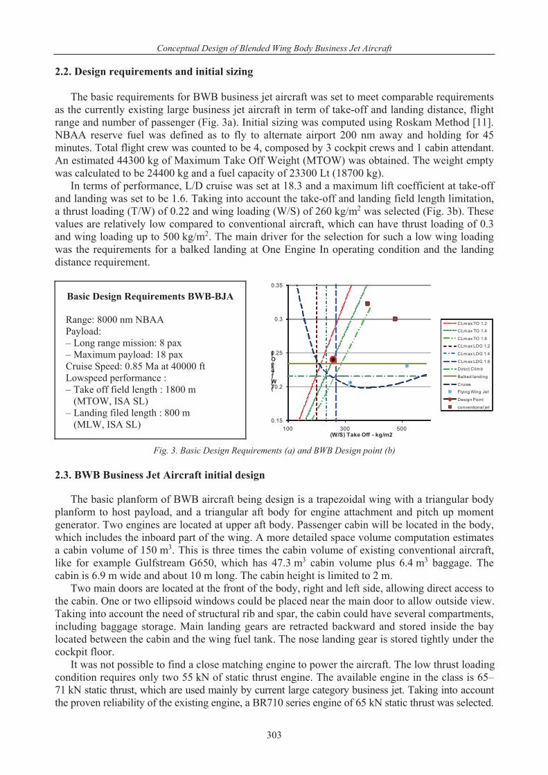
The basic requirements for BWB business jet aircraft was set to meet comparable requirements as the currently existing large business jet aircraft in term of take-off and landing distance, flight range and number of passenger (Fig. 3a). Initial sizing was computed using Roskam Method [11]. NBAA reserve fuel was defined as to fly to alternate airport 200 nm away and holding for 45 minutes. Total flight crew was counted to be 4, composed by 3 cockpit crews and 1 cabin attendant. An estimated 44300 kg of Maximum Take Off Weight (MTOW) was obtained. The weight empty was calculated to be 24400 kg and a fuel capacity of 23300 Lt (18700 kg).
In terms of performance, L/D cruise was set at 18.3 and a maximum lift coefficient at take-off and landing was set to be 1.6. Taking into account the take-off and landing field length limitation, a thrust loading (T/W) of 0.22 and wing loading (W/S) of 260 kg/m2 was selected (Fig. 3b). These values are relatively low compared to conventional aircraft, which can have thrust loading of 0.3 and wing loading up to 500 kg/m2. The main driver for the selection for such a low wing loading was the requirements for a balked landing at One Engine In operating condition and the landing distance requirement.
Basic Design Requirements BWB-BJA Range: 8000 nm NBAA Payload: – Long range mission: 8 pax – Maximum payload: 18 pax Cruise Speed: 0.85 Ma at 40000 ft Lowspeed performance : – Take off field length : 1800 m
(MTOW, ISA SL) – Landing filed length : 800 m
(MLW, ISA SL)
0.15
0.2
0.25
0.3
0.35
100 300 500
(T/W) Take Off
(W/S) Take Off - kg/m2
CLm ax TO 1.2
CLm ax TO 1.4
CLm ax TO 1.6
CLm ax LDG 1.2
CLm ax LDG 1.4
CLm ax LDG 1.6
Direct Clim b
Balked landing
Cruise
Flying Wing Jet
Design Point
conventional jet
Fig. 3. Basic Design Requirements (a) and BWB Design point (b) 2.3. BWB Business Jet Aircraft initial design
The basic planform of BWB aircraft being design is a trapezoidal wing with a triangular body planform to host payload, and a triangular aft body for engine attachment and pitch up moment generator. Two engines are located at upper aft body. Passenger cabin will be located in the body, which includes the inboard part of the wing. A more detailed space volume computation estimates a cabin volume of 150 m3. This is three times the cabin volume of existing conventional aircraft, like for example Gulfstream G650, which has 47.3 m3 cabin volume plus 6.4 m3 baggage. The cabin is 6.9 m wide and about 10 m long. The cabin height is limited to 2 m.
Two main doors are located at the front of the body, right and left side, allowing direct access to the cabin. One or two ellipsoid windows could be placed near the main door to allow outside view. Taking into account the need of structural rib and spar, the cabin could have several compartments, including baggage storage. Main landing gears are retracted backward and stored inside the bay located between the cabin and the wing fuel tank. The nose landing gear is stored tightly under the cockpit floor.
It was not possible to find a close matching engine to power the aircraft. The low thrust loading condition requires only two 55 kN of static thrust engine. The available engine in the class is 65–71 kN static thrust, which are used mainly by current large category business jet. Taking into account the proven reliability of the existing engine, a BR710 series engine of 65 kN static thrust was selected.
303

T. Mulyanto, M. L. I. Nurhakim
Initial definition of several basic geometry parameters such as sweep angle, Aspect Ratio and thickness distribution was difficult to acquire. Information found in [12] was found to be useful. A typical supercritical airfoil was used at section 60 %span up to the tip. Thickness distribution at the centre section was defined to satisfy a certain cabin height as shown in Fig. 4a. a)
3.5
3
2.5
2
1.5
1
0.5
0
0.5
1
0%
2%
4%
6%
8%
10%
12%
14%
16%
18%
20%
0% 20% 40% 60% 80% 100%
Span location, half span
t/c max
twist, deg
b)
Fig. 4. Thickness and twist distribution (a), and Cabin and Fuel tank volume allocation (b)
The main front and rear spar is illustrated in Fig. 4b. They will constitute the major structures
to receive bending load. As mentioned in the design consideration, a strong, rigid and thick skin will be used for the inner wing skin forming the shell of the cabin. A rib in the centre of the cabin would prevent the upper and lower skin to collapse while taking the bending load.
For pitch control, a set of elevons are used. Spoilers are used for additional lateral control and as lift damper during landing. Directional control was performed by winglet rudder. The outer most elevons can be used as drag-ruddervons to improve directional control authority. In this mode, a differential drag between each wing can be generated resulting in a yawing moment. Leading edge flaps are used to increase lift coefficient (Fig. 5).
Fig. 5. Three view drawing of BWB BJA (insert picture: comparison with G500)
Mean aerodynamic chord (mac) was estimated for the basic trapezoidal wing. A detail calculation
on the pressure distribution calculates the aircraft Neutral Point (NP) at 50.5% mac. Note that the NP location is much more aft than simple wing geometry, which is about 25-30% mac. This is due to the existence of aft body geometry, which constitutes a considerable amount of lifting area. With
304

Conceptual Design of Blended Wing Body Business Jet Aircraft
this position, a total cg location permitting +5% static margin can be reasonably achieved. With a payload only 2% to 4% of Maximum Take Off Weight, the cg travel was found to be only between -4% to +1%. Wing fuel tank should be designed with several compartments allowing controlled fuel consumption between compartments to maintain cg location.
Figure 5 shows an initial design of BWB Business Jet Aircraft. The overall length is 20.2 m, wing span of 34.4 m, and overall span of 35.9 m. The aircraft overall height is 6.15 m. A three view drawing comparison with Gulfstream G500 is also presented in Fig. 5. It can be seen that the BWB design has 7.4 m longer wing span, but 9.2 m shorter than the conventional aircraft length. Despite a relatively comparable dimension between the two, BWB configuration offers a cabin volume about 3 times bigger than the conventional one. 3. Initial aerodynamic analysis
An Initial aerodynamic analysis was conducted using commercial CFD code. The focus was on the main basic geometry, which excludes the effect of wingtip and engine nacelle. The analysis was run for several angles of attack (AoA) at 0.85 Mach. A smooth pressure gradient on the upper and lower body surface was obtained. The pressure distribution information permits to estimate the location of aerodynamic centre, which constitute the neutral point of the aircraft. A positive pitching moment was also obtained. As can be seen in Fig. 6, positive pressure at the upper surface generates a negative lift on the aft part of the body. Cruise condition was obtained at AoA of 3 degree. Weak shockwave started to generate at AoA 4 degree. a)
b)
Fig. 6. Pressure distribution of lower (left side) and upper (right side) surface: AoA 2 deg (a), AoA 4 deg (b)
From the pressure distribution results, spanwise lift distribution and local lift coefficient
distribution was calculated as shown in Fig. 7. The lift distribution was found to be not ideal. The body section produce too much less lift. Further BWB geometry refinement and optimization is required. The local lift coefficient distribution trend is acceptable, but the magnitude has to be improved. Greater lift coefficient is necessary near the centre section and less in the outboard section. a)
0
0.1
0.2
0.3
0.4
0.5
0.6
0.7
0.8
0
10000
20000
30000
40000
50000
60000
Lift(N)
Lift Local cl
b)
0
0.1
0.2
0.3
0.4
0.5
0.6
0.7
0.8
0
10000
20000
30000
40000
50000
60000
Lift(N)
Lift Local cl
Fig. 7. Spanwise lift and cl distribution: AoA 2 deg (a), AoA 4 deg (b)
305

T. Mulyanto, M. L. I. Nurhakim
4. Concluding remarks
In this study, an initial design of business jet aircraft with Blended Wing Body configuration was obtained based on a typical requirement for a long-range large business jet aircraft. The design resulted in a comparable aircraft size with that of conventional configuration, but BWB configuration offer much more cabin volume.
A preliminary CFD analysis on the basic design has shown that a smooth pressure distribution was obtained to avoid shockwave formation in cruise condition. More iteration has to be made to improve spanwise lift distribution. Further, analysis of nacelle and winglet effect would be necessary to understand better their impact on the basic design geometry. References [1] Anonymous, Business Aircraft Market Forecast 2012-2031, Bombardier, 2012. [2] Anonymous, The VELA Project, DLR, Martin Hepperle, downloaded at www.dlr.de/as/en/
desktopdefault.aspx/tabid-370/, 2005. [3] Carter, M. B., Dan, D., Vicroy, D. D., Patel, D., Transonic Aerodynamics: Summary of Ground
Tests and Sample Results (Invited), Proceeding of 47th AIAA Aerospace Sciences Meeting and Exhibit, USA 2009.
[4] Djojodihardjo, H., Wei, A. K. L., Conceptual Design and Aerodynamic Study of Blended Wing Body Business Jet, Proceeding of 28th International Congress of the Aeronautical Sciences, Brisbane 2012.
[5] Ikeda, T., Aerodynamic Analysis of a Blended-Wing-Body Aircraft Configuration, Master Thesis, RMIT, 2006.
[6] Liebeck, R. H., Design of the Blended Wing Body Subsonic Transport, Journal of Aircraft, Vol. 41, No. 1, 2004.
[7] Meheut, M., Grenon, G., Carrier, G., Defos, M., Duffau, M., Aerodynamic Design of Transonic Flying Wing Configurations, Proceeding of CEAS/KATnet II Conference on Key Aerodynamic Technologies, Bremen, Germany 2009.
[8] Mukhopadhyay, V., Sobieszczanski-Sobieski, J., Kosaka, I., Quinn, G., Charpentier, C., Analysis Design and Optimization of Non-cylindrical Fuselage for Blended-Wing-Body (BWB) Vehicle, AIAA 2002-5664 paper, 2002.
[9] Okun, D. T., Williamson, I. A., Pearson, D. R., Aranoff, S. L., Pinkert, D. A., Johanson, D. S., Business Jet Aircraft Industry: Structure and Factors Affecting Competitiveness, United States International Trade Commission Report, April 2012.
[10] Qin, N., Vavalle, A., Le Moigne, A., Laban, M., Hackett, K., Weinerfelt, P., Aerodynamic Studies for Blended Wing Body Aircraft, Proceeding of 9th AIAA/ISSMO Symposium on Multidisciplinary Analysis and Optimization, Atlanta, Georgia 2002.
[11] Roskam, J., Airplane Design, Roskam Aviation and Engineering Corporation, 1986. [12] Staelens, Y. D., Study of Belly-Flaps to Enhance Lift and Pitching Moment Coefficient of
a Blended Wing Body Airplane in Landing and Takeoff Configuration, PhD Thesis, University of Southern California, USA 2007.
[13] Velicki, A., Jegley, D., PRSEUS Development for the Hybrid Wing Body Aircraft, Proceeding of 11th AIAA Aviation Technology, Integration, and Operation, USA 2011.
[14] Vicroy, D. X-48B Blended Wing Body Ground to Flight Correlation Update, AIAA Aero Science Meeting, 2011.
306