conceptual design of a fixture-based reconfigurable spot
TRANSCRIPT

Conceptual Design of a Fixture-Based Reconfigurable Spot Welding System
Michael Allan Sequeira
Thesis presented in partial fulfilment of the requirements for the degree of Master of Science in Engineering
(Mechatronics) at Stellenbosch University
Department of Mechanical and Mechatronic Engineering Stellenbosch University
Supervisor: Prof A.H. Basson
September 2008

Declaration
I, the undersigned, hereby declare that the work contained in this thesis is my own original work and that I have not previously in its entirety or in part submitted it at any university for a degree.
Signature: ……………………….
Date: ……………………………
Copyright © 2008 Stellenbosch University
All rights reserved.

i
Abstract
Conceptual Design of a Fixture-Based Reconfigurable Automated Spot Welding System
M. A. Sequeira
Department of Mechanical and Mechatronic Engineering Stellenbosch University
Private Bag X1, 7602 Matieland, South Africa
Thesis: MScEng (Mechatronics)
September 2008
This thesis details the conceptual design of a fixture-based, reconfigurable, automated spot welding system aimed at manufacturing various sub-assemblies of circuit breakers. The welding operations are currently done using manual welding equipment, making this stage of the assembly process highly labour intensive. A range of product models and variants are assembled in quantities requiring frequent change-overs. Low-cost automation within a developing country’s manufacturing industry, more specifically within the Republic of South Africa, is the target context. The chosen design restriction, of incorporating a part fixturing design approach, distinguishes this research from F. S. D. Dymond’s work, who addressed the same problem while restricted to a fixtureless assembly approach.
A conceptual layout design was developed to address part feeding, manipulation, transportation, fixturing and welding requirements, for an entire breaker model range. A simulation model for three possible layouts of the selected conceptual design provided a means to investigate each layout’s ability to tolerate and balance variation in production requirements, and to establish objective comparative performance data. This showed that the optimal configuration consists of four single loop layout systems.
The thesis concludes that the final concept possesses the flexibility to produce the primary product range. Reconfiguration for production beyond this range is assisted by the modular nature of the layout. Ultimately, a reconfigurable design should focus on a properly selected base of core product ranges, providing an expandable and reusable system. The system can be supported by manual assembly stations which handle highly variant, incompatible product ranges.

ii
Uittreksel
Konseptuele Ontwerp van ʼn Setmaat-Gebaseerde Herkonfigureerbare Outomatiese Puntsweisstelsel
M. A. Sequeira
Departement Meganiese en Megatroniese Ingenieurswese Stellenbosch Universiteit
Privaatsak X1, 7602 Matieland, Suid Afrika
Tesis: MScEng (Megatronies)
September 2008
Hierdie tesis bespreek die konsepontwerp van 'n setmaat-gebaseerde, herkonfigureerbare, outomatiese puntsweisstelsel wat gemik is op die vervaardiging van verskeie sub-samestellings van stroombrekers. Die sweisbewerkings word tans met handbeheerde sweistoerusting gedoen, wat hierdie stadium van die samestellingsproses baie arbeidsintensief maak. 'n Reeks produkmodelle en –variante word saamgesel in hoeveelhede wat gereelde omskakelings vereis. Lae-koste outomatisasie binne 'n ontwikkelende land se vervaardigingsindustrie, spesifiek binne die Republiek van Suid-Afrika, is die toepassingskonteks. Die beperking wat doelbewus in die ontwerp gekies is, nl. om setmate te gebruik, onderskei die navorsing van dié van F.S.D. Dymond, wat dieselfde probleem aangespreek het, maar met die beperking dat setmate nie gebruik word nie.
'n Konsep uitleg-ontwerp is ontwikkel wat die vereistes aanspreek vir onderdeel voer, onderdeel manipulasie, vervoer, setmaatgebruik en sweisbewerkings, vir 'n hele stroombreker-produkreeks. 'n Simulasiemodel vir drie moontlike uitlegte van die gekose konsepontwerp, het die geleentheid gegee om elke uitleg se vermoë om produksie-wisselings te verdra en balanseer, te ondersoek en om objektiewe vergelykende werkverrigtingsdata daar te stel. Dit het getoon dat die optimale konfigurasie bestaan uit vier enkellus uitleg sisteme.
Die tesis kom tot die gevolgtrekking dat die finale konsep oor die aanpasbaarheid beskik om die primêre produkreeks te vervaardig. herkonfigurasie vir produksie buite hierdie reeks word vergemaklik deur die modulêre aard van die uitleg. Dit is beslissend dat herkonfigureerbare ontwerp moet fokus op 'n behoorlik gekose basis van kern-produkreekse, wat 'n uitbreibare en herbruikbare stelsel lewer. Die stelsel kan ondersteun word deur handsamestellingswerkstasies wat produkreekse hanteer wat grootliks varieer en onversoenbaar is.

iii
To Sandra
My love, my life and everything in between…

iv
Acknowledgements
I wish to express my sincere gratitude to everyone who has contributed to this thesis in any way. In particular, I would like to thank the persons below:
Professor A.H. Basson for his valuable advice, criticisms and guidance during the course of the research.
My co-student in the quest for reconfiguration, Francois Dymond, for many entertaining discussions concerning the difference between reconfigurability and flexibility.
Louis Kaltenreider and Johan Enslin of CBI’s automation division for all their advice, patience and effort provided.
Stuart Dersley, Colin Rothery and Harry Steyn of Tectra Automation for their help regarding the costing and implementation advice for the pallet system.
Theunis Taljaard of Ingenior and Alfred Grau of AGM maschinenbau for their help regarding the design of automation systems. Their comments and advice from industry are appreciated.
My fellow students, Chudi Egbuna, Willie van der Merwe, Pieter Greef and Robert Alink, who I have had the pleasure of sharing an office with over the past two years.
My parents for their unconditional love, patience and encouragement throughout my life, for which I am truly blessed.

v
Contents
Abstract i
Uittreksel ii
Acknowledgements iv
Contents v
List of Figures ix
List of Tables xii
Abbreviations xiii
1 Introduction 1
1.1 Background ........................................................................................................................................ 1
1.2 Objectives ........................................................................................................................................... 2
1.3 Motivation .......................................................................................................................................... 2
1.4 Scope of Study ................................................................................................................................... 3
2 Literature Review 5
2.1 Introduction ....................................................................................................................................... 5
2.2 Common Terms and Definitions .................................................................................................... 7
2.3 Feeding Systems................................................................................................................................. 9
2.3.1 Non-vision based feeding systems ............................................................................ 9
2.3.2 Vision based feeding systems ................................................................................... 10
2.4 Part Manipulators ............................................................................................................................ 12
2.5 Work Fixtures .................................................................................................................................. 15
2.6 Work Station: Resistance Welding ................................................................................................ 18
2.7 Simulation Software Review .......................................................................................................... 21
2.7.1 Mechanical mechanism analysis ............................................................................... 22
2.7.2 Robotic assembly simulation .................................................................................... 23
2.7.3 Material handling simulation .................................................................................... 24
2.7.4 Resistance welding simulation .................................................................................. 24

vi
3 Case Study Background 26
3.1 Introduction ..................................................................................................................................... 26
3.2 Product Assembly Details .............................................................................................................. 27
3.2.1 The Q-frame ............................................................................................................... 27
3.2.2 Other frames (B, C and D) ....................................................................................... 29
3.3 Existing Production Scenario ........................................................................................................ 29
3.4 Typical Production Information ................................................................................................... 31
4 Conceptual Development 33
4.1 Introduction ..................................................................................................................................... 33
4.2 Part Feeding ..................................................................................................................................... 33
4.2.1 Pigtails .......................................................................................................................... 33
4.2.2 Moving contact (MC) ................................................................................................ 35
4.2.3 Handle frame assembly (HFA) ................................................................................ 36
4.2.4 Coil ............................................................................................................................... 38
4.2.5 Arc runner (AR) ......................................................................................................... 39
4.3 Manipulation Devices ..................................................................................................................... 40
4.3.1 Pick and place stations .............................................................................................. 40
4.3.2 Robotic grippers ......................................................................................................... 41
4.3.3 Cartesian gantry .......................................................................................................... 43
4.4 Part Fixturing ................................................................................................................................... 44
4.5 Weld Station ..................................................................................................................................... 45
4.5.1 Robotic weld gun ....................................................................................................... 45
4.5.2 Gantry mounted weld head ...................................................................................... 45
4.5.3 Electrode configuration ............................................................................................ 46
4.5.4 Active part clamping .................................................................................................. 47
4.6 Conceptual Layout Design ............................................................................................................. 47
4.6.1 Layout 1: Rotary index assembly table .................................................................... 48
4.6.2 Layout 2: Linear index assembly line ...................................................................... 49
4.6.3 Layout 3: Grooved track pallet assembly ............................................................... 50
4.6.4 Layout 4: Loose pallet assembly .............................................................................. 52

vii
4.7 Final Concept Selection .................................................................................................................. 54
5 System Embodiment Design 56
5.1 Introduction ..................................................................................................................................... 56
5.2 TS 2plus Transfer System ............................................................................................................... 56
5.2.1 Single loop layout variation (Model 1) .................................................................... 56
5.2.2 Double loop layout variation (Model 2) ................................................................. 57
5.2.3 Triple loop layout variation (Model 3) .................................................................... 58
5.2.4 Conveyor modules ..................................................................................................... 58
5.2.5 Pallets and fixtures ..................................................................................................... 59
5.2.5 Stop gates and lift positioning units ........................................................................ 60
5.2.6 Mobile data units ........................................................................................................ 60
5.3 Part Manipulation ............................................................................................................................ 61
5.3.1 Pick and place modules ............................................................................................. 61
5.4 Resistance Weld Station .................................................................................................................. 63
5.4.1 Electrode configuration ............................................................................................ 63
5.4.2 Mini resistance welding system ................................................................................ 64
5.4.3 Welding gantry ............................................................................................................ 65
5.4.4 Weld paste/tape requirements ................................................................................. 66
5.5 Quality Control Strategy ................................................................................................................. 67
6 System Simulation 69
6.1 Introduction ..................................................................................................................................... 69
6.2 Objectives and Optimization Requirements ............................................................................... 69
6.3 Model Design ................................................................................................................................... 70
6.3.1 Processing time definition ........................................................................................ 71
6.3.2 User defined variable values ..................................................................................... 71
6.3.2 Conveyor segment definition ................................................................................... 72
6.3.4 Planned failure definition .......................................................................................... 73
6.4 Simulation Results ........................................................................................................................... 73
6.5 Conclusions ...................................................................................................................................... 75
7 Cost Estimation 78

viii
8 Conclusions 80
Appendix A 83
Arena® Program Development .................................................................................................................... 83
A.1 Create Pallets and Round Robin on Main ................................................................................... 84
A.2 RFID Control .................................................................................................................................. 85
A.2.1 Reconfiguration control via station 2 ...................................................................... 87
A.2.2 Feed loop entry control at stations 3 and 5 ............................................................ 88
A.2.3 Weld loop entry control at stations 9 and 11 ......................................................... 88
A.2.4. Remove loop entry control at station 13 ................................................................ 88
A.2.5 Release pallets to main loop at exit stations 4, 6, 10, 12, and 14 ......................... 89
A.2.6. Reset the JobStep at station 15 ................................................................................ 89
A.2.7 Else convey on main conveyor ................................................................................ 89
A.3 Feed Subloop 1 ................................................................................................................................ 89
A.4 Weld Subloop 3 ............................................................................................................................... 90
A.5 Remove Subloop 5 .......................................................................................................................... 91
A.6 Model Condition Indicators ........................................................................................................... 91
A.6.1 User defined variables ............................................................................................... 91
A.6.2 Processing time definition ........................................................................................ 92
A.6.3 Sequence definition .................................................................................................... 93
A.6.4 Conveyor definition ................................................................................................... 93
A.6.5 Conveyor segment definition ................................................................................... 93
A.6.6 Planned failure definition .......................................................................................... 93
A.6.7 Simulation replication parameters ........................................................................... 94
A.7 Simulation Parameter Optimization ............................................................................................. 94
Appendix B 96
Cost Estimation ............................................................................................................................................... 96
9 List of References 98

ix
List of Figures
Figure 2.1: Basic reconfigurable automated assembly functional decomposition............... 6
Figure 2.2: Schematic of vision based flexible parts feeder (Causey, 1999) ....................... 11
Figure 2.3: Adept Anyfeeder™ system representation (Adept, 2008), ............................... 11
Figure 2.4: Mobile parts feeder mounted on a courier (Quaid, 1999) ................................ 12
Figure 2.5: Underside of a planar linear motor (Quaid et al., 1997).................................... 13
Figure 2.6: Cross section of nozzle (left); Nozzles handling carton (right) (Ozcelik et al.,
2003) ............................................................................................................................................. 14
Figure 2.7: (a) Assembled pocket gripper; (b) Gripper tested with 5 kg hemispherical
part; (c) Gripper placing an egg. (Choi and Koc, 2006) ........................................................ 14
Figure 2.8: Intelligent three-fingered gripper (Feldmann et al., 2005) ................................ 15
Figure 2.9: Flexible fixturing system (Arzanpour et al., 2006) ............................................. 16
Figure 2.10: 6 DOF reconfigurable gripper (Yeung and Mills, 2004) ................................. 17
Figure 2.11: Kinematic diagram of reconfigurable gripper (Yeung and Mills, 2004) ....... 17
Figure 2.12: Rubber pocket flexible fixturing device (Choi and Koc, 2006) ..................... 18
Figure 2.13: Robotic weld gun mounted on X-Y gantry (Bloss, 2006) .............................. 19
Figure 2.14: series configuration weld head (left); opposed configuration (right) (Miyachi
Unitek, 2005) ............................................................................................................................... 20
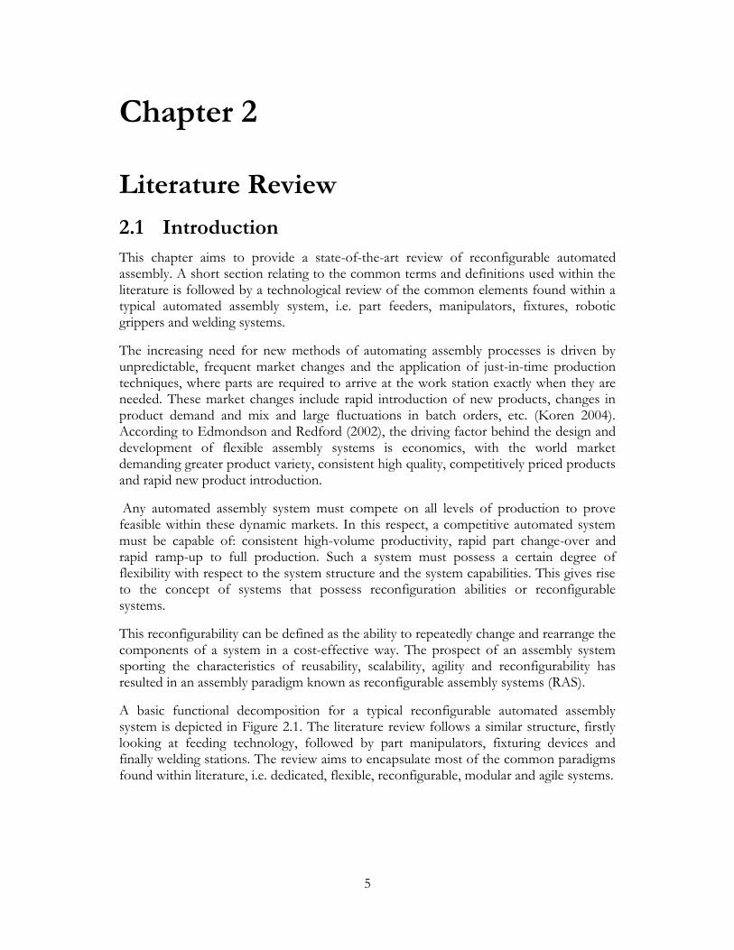
Figure 2.15: RSX 50 automated spot welding systems (Techmatrix, 2007) ....................... 21
Figure 2.16: COSIMIR® work cell window examples (Cosimir Getting Started, 2001) . 23
Figure 3.1: Circuit breaker frames Q, B, C and D ................................................................. 26
Figure 3.2: Q-frame breaker mechanism assembly ................................................................ 28
Figure 3.3: Internal view of assembled Q-frame in closed switch position ....................... 28
Figure 3.4: D, C and B frame circuit breaker sub-assemblies .............................................. 29
Figure 3.5: (a) Pigtail cutting machine; (b) Manual welding stations ................................... 30
Figure 3.6: Mandrel weld fixture for coil alignment to HFA ............................................... 31

x
Figure 4.1: (a) Tumbling barrel feeder; (b) Comtech linear feed tracks (Comtech, 2008) 35
Figure 4.2: Moving contact CAD representation .................................................................. 36
Figure 4.3: Handle frame assembly CAD representation ..................................................... 36
Figure 4.4: HFA feeding via plastic handle hanging on rails ................................................ 37
Figure 4.5: HFA magazine indexing feed system ................................................................... 38
Figure 4.6: Q-frame coil samples ............................................................................................. 38
Figure 4.7: Passive coil reorientation mechanism .................................................................. 39
Figure 4.8: Arc runner CAD representation ........................................................................... 39
Figure 4.9 (a) AR out-feed track swing cut-out; (b) AR rotator mechanism ..................... 40
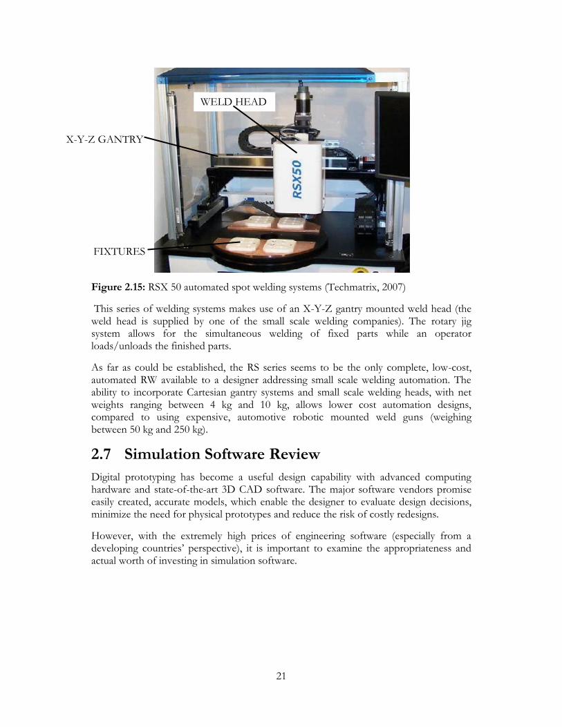
Figure 4.10: Gripper handling points ...................................................................................... 42
Figure 4.11: Part alignment requirements ............................................................................... 44
Figure 4.12: Current wave form for DC inverter type and common AC type power
supplies (Miyachi Unitek, [s.a.]) ................................................................................................ 46
Figure 4.13: Basic electrode configurations ............................................................................ 46
Figure 4.14: Layout 1.................................................................................................................. 49
Figure 4.15: Layout 2.................................................................................................................. 50
Figure 4.16: Layout 3.................................................................................................................. 51
Figure 4.17: Linear assembly system LS280 cam drive mechanism (Weiss, 2007]) .......... 51
Figure 4.18: ecoTrans® system chain drive mechanism (Aci-ecotec, [s.a.]) ...................... 52
Figure 4.19: Actual application example: ecoTrans® system (Aci-ecotec, [s.a.]) .............. 52
Figure 4.20: Layout 4.................................................................................................................. 53
Figure 4.21: Conveyor tracks and lift position unit (Bosch Rexroth, 2006) ...................... 54
Figure 5.1: Single loop layout variation (Model 1) ................................................................. 57
Figure 5.2: Triple loop layout variation (Model 3) ................................................................. 58
Figure 5.3: TS 2plus basic conveyor modules ........................................................................ 59
Figure 5.4: Pallet and fixture CAD representation ................................................................ 60
Figure 5.5: Decentralised data storage layout (Bosch Rexroth, 2007) ................................ 61
Figure 5.6: Freely programmable HP 140T pick and place unit (Weiss, 2008) ................. 62
Figure 5.7: Mini resistance welding system arrangement (Miyachi Unitek2, [s.a.]) ........... 64

xi
Figure 5.8: 4 DOF Cartesian gantry representation (Bosch Rexroth2, 2007) ................... 65
Figure 5.9: Dual automatic electrode dresser with removable cutter units (Rotech, 2001)
....................................................................................................................................................... 66
Figure 6.1: Model 1, Model 2 and Model 3 (top view CAD representations) ................... 70
Figure A.1: Top level logic structure for Model 2 ................................................................. 83
Figure A.2: Animation layout for Model 2 showing the 15 main loop stations ................ 83
Figure A.3: Sub-level logic: create pallets and round robin on main conveyor ................. 84
Figure A.4: Sub-level logic: RFID control .............................................................................. 86
Figure A.5: Sub-sub-level logic: reconfigure feedloop1 ........................................................ 87
Figure A.6: Sub-sub-level logic: exit subloop ......................................................................... 89
Figure A.7: Sub-level logic: feed subloop 1 ............................................................................ 90
Figure A.8: Sub-level logic: weld subloop 3 ............................................................................ 90
Figure A.9: Sub-level logic: remove subloop 5 ....................................................................... 91
Figure A.10: Optimum number of pallets for Model 2 ........................................................ 95

xii
List of Tables
Table 3.1: Q-frame mechanism part variation ........................................................................ 27
Table 3.2: Cost breakdown per unit welded .......................Error! Bookmark not defined.
Table 3.3: Approximate daily frame production rates .......Error! Bookmark not defined.
Table 3.4: Q-frame production variation ................................................................................ 32
Table 5.1: Gripper specifications.............................................................................................. 62
Table 6.1: Processing time definition for load, weld and remove processes ..................... 71
Table 6.2: Number of pallets per a Model .............................................................................. 72
Table 6.3: Main loop lengths for Model 1, 2 and 3 ............................................................... 72
Table 6.4: Parallel loop lengths for Model 2 and 3 ................................................................ 72
Table 6.5: Model 1 production batch distribution ................................................................. 74
Table 6.6: Model 2 production batch distribution ................................................................. 74
Table 6.7: Model 3 production batch distribution ................................................................. 75
Table 6. 8: Model 1, 2 and 3 system hardware comparison ................................................. 76
Table 7. 1: System cost comparison ......................................................................................... 78
Table B.1: Costing overview: four Model 1 systems ............................................................. 96
Table B.2: Costing overview: two Model 2 systems .............................................................. 97

xiii
Abbreviations
AGV Automated Guided Vehicles
AMTS Advanced Manufacturing Technology Strategy
AR Arc Runner
CBI Circuit Breaker Industries
DFA Design For Assembly
DML Dedicated Manufacturing Line
DOF Degrees of Freedom
FFA Flexible Fixtureless Assembly
FMS Flexible Manufacturing System
HFA Handle Frame Assembly
MC Moving Contact
RAS Reconfigurable Assembly System
RFID Radio Frequency Identification
RMS Reconfigurable Manufacturing System
RW Resistance Weld

1
Chapter 1
Introduction
1.1 Background
This thesis details the conceptual design of a reconfigurable spot welding system, for various sub-assembly components, of a family of circuit breakers manufactured by CBI (Circuit Breaker Industries) Ltd. The emphasis of the project is the investigation and evaluation of generic low cost automation techniques which can be applied in the design of reconfigurable assembly systems.
The research falls under the AMTS (Advanced Manufacturing Technology Strategy) initiative, a national strategy under the Department of Science and Technology. AMTS aims to achieve the governmental initiative of developing technologies that will impact positively on the automotive and manufacturing industries of the Republic of South Africa. The research presented here is part of a project aimed at developing a conceptual design of a reconfigurable manufacturing system. The project forms part of the “Affordable Automation” theme of AMTS.
CBI has, due to certain manual labour issues (skilled labour availability, labour management requirements, etc.), investigated automation possibilities within their manufacturing and assembly stages. However, the available solutions were supplied by international companies, and did not suit the production volumes of CBI.
Traditionally, the product design sequence, for systems addressing high production volumes, entails the design of the product first, followed by the design of the manufacturing/assembly system. This “product-driven process” results in the manufacturing equipment being highly dedicated and unable to respond to any sort of product variation. Initial efforts to address these limitations of dedicated systems saw the introduction of flexible manufacturing systems (FMS), which are designed to produce a complete family of similar parts. A CNC milling machine is often used as an example of an FMS, since they can produce a variety of parts by changing the tooling and the programmable tool paths, however, they have a predominantly fixed mechanical configuration. CNC machine designers do not know what level of flexibility and functionality will be required for a specific product to be produced on the machine, resulting in the machines being “over designed” to meet the requirements of all prospective clients. This often leads to a customer paying for machining capability that may never be required or used, resulting in “wasted” capital investment.

2
Reconfigurable manufacturing systems (RMS), Koren et al. (1999), are proposed as alternatives to these contemporary FMSs and are seen as a compromise between flexible and dedicated manufacturing systems. An RMS aims to provide an effective mix of flexible and dedicated equipment, which is expandable and whose functionality and productivity can readily be changed when needed.
1.2 Objectives
The goal of the thesis research is to complete the conceptual/layout design of a reconfigurable spot welding system, for the automated assembly of specific sub-assemblies of a circuit breaker family, which are currently assembled by hand.
The conceptual system will be evaluated with respect to:
Reconfigurability per defined characteristics (modularity, customized flexibility, scalability, reusability, etc.).
System ramp-up time between reconfigurations.
Production rate optimization after reconfiguration.
Failure, quality control and maintenance contingencies applicable to reconfigurable systems
The proposed design must address issues such as:
Economic feasibility for the company
Other breaker family applicability
Low cost automation requirements
Acceptable change over times
Geographical location of the assembly plant (Lesotho)
Availability of expertise (limited onsite technical personnel) to maintain, setup and run the system.
1.3 Motivation
Research into reconfigurable assembly systems, aimed at the manufacturing industry of South Africa, can provide a basis for relevant stakeholders to specifically identify:
Technologies that can assist the manufacturing industry with retrofitting conventional machines and processes with more flexible systems.
Technologies that can assist the manufacturing industry with the integration of low cost, plug-and-play hardware and controllers for automated machines.
Technologies that provide customized flexibility, expandability and modularity and that are specifically designed with reconfiguration in mind.

3
Furthermore, investigation of automation as a feasible option, which can competitively provide a company with an alternative to manual labour, is of high interest within a country such as South Africa where increasing labour rates are threatening some manufacturing industries.
The use of circuit breaker assembly, as a case study, provides the research with a direct link to the South African manufacturing industry, as well as a suitable variation in a family of products. CBI also has complete design, manufacture and assembly control over their entire product range (almost no out-sourcing of work occurs). They therefore represent a typical company which is striving to be competitive on an international level, while being based in a developing country.
The welding operations, required for the assembly of a circuit breaker, were selected for various reasons, as the focus of this study. This stage in the assembly provides a means to investigate the typical functions normally required for an automated assembly system. This is:
The singulation, orientation and presentation of the parts within a feeding subsystem.
The manipulation of the parts into fixturing devices.
The transportation and accurate positioning of the parts for processing.
The use of the very common method of resistance welding.
From CBI’s perspective, the welding requirements are seen as perpetual management, labour, quality and production hurdles, within the overall production sequence. They are therefore considerably interested in alternatives to the current situation and see this research as a form of an external feasibility study.
1.4 Scope of Study
Initial consideration of the assembly problem saw the identification of two possible approaches to the system design. The one approach is seen as the more conventional fixture-based assembly, where the parts are assembled and processed within a mechanical fixture while the other is a robot based fixtureless assembly approach, where the parts are held by a robot during processing.
The chosen design restriction of incorporating a part fixturing approach therefore distinguishes the research presented here from a co-students work (Dymond, 2009), who addressed the same problem with a robot-based fixtureless design.
The concept development and layout designs encompass the identification and interfacing of low-cost, off-the-shelf sub-systems (compared to specialized purpose built equipment). These sub-systems are selected to provide a modular distribution of flexible and dedicated functional units, within a larger reconfigurable layout design.

4
CBI’s flagship family of circuit breakers (Q-frame range) is used as the primary part family for this design investigation. However, three other ranges of frames are introduced to provide a real-world situation were a full system reconfiguration would be required to expand the capabilities beyond the design for the Q-frame. This provides a platform for the identification of reconfiguration challenges that accompany a complete product change-over.
However, at this point it must be reiterated that the primary focus of the thesis is the investigation of the feasibility and design methodology for a reconfigurable assembly systems in general, and not finding a solution for the assembly of the breakers described as a case study.
Also note that due to the broad, system wide focus of this research and limited time, the detail pertaining to a suitable reconfigurable/holonic control strategy was not considered.
5
Chapter 2
Literature Review
2.1 Introduction
This chapter aims to provide a state-of-the-art review of reconfigurable automated assembly. A short section relating to the common terms and definitions used within the literature is followed by a technological review of the common elements found within a typical automated assembly system, i.e. part feeders, manipulators, fixtures, robotic grippers and welding systems.
The increasing need for new methods of automating assembly processes is driven by unpredictable, frequent market changes and the application of just-in-time production techniques, where parts are required to arrive at the work station exactly when they are needed. These market changes include rapid introduction of new products, changes in product demand and mix and large fluctuations in batch orders, etc. (Koren 2004). According to Edmondson and Redford (2002), the driving factor behind the design and development of flexible assembly systems is economics, with the world market demanding greater product variety, consistent high quality, competitively priced products and rapid new product introduction.
Any automated assembly system must compete on all levels of production to prove feasible within these dynamic markets. In this respect, a competitive automated system must be capable of: consistent high-volume productivity, rapid part change-over and rapid ramp-up to full production. Such a system must possess a certain degree of flexibility with respect to the system structure and the system capabilities. This gives rise to the concept of systems that possess reconfiguration abilities or reconfigurable systems.
This reconfigurability can be defined as the ability to repeatedly change and rearrange the components of a system in a cost-effective way. The prospect of an assembly system sporting the characteristics of reusability, scalability, agility and reconfigurability has resulted in an assembly paradigm known as reconfigurable assembly systems (RAS).
A basic functional decomposition for a typical reconfigurable automated assembly system is depicted in Figure 2.1. The literature review follows a similar structure, firstly looking at feeding technology, followed by part manipulators, fixturing devices and finally welding stations. The review aims to encapsulate most of the common paradigms found within literature, i.e. dedicated, flexible, reconfigurable, modular and agile systems.

6
RECONFIGURABLE AUTOMATED
ASSEMBLY FUNCTIONAL
DECOMPOSITION
Feed parts into
system
Manipulate
fed-in parts
Fix parts for
work stationWork
Station
Dispense
parts
Align for
manipul
ation
Guide
orderly
Reconfigure
Feeder
Feed to
correct
work
station
Flip parts Fix/Hold
parts
Present
parts at
work
station
Complete
assemblies
dispensed to
environment
Incomplete
assemblies
rerouted for
additional
assembly
Change
work
head
Align
work
head
Select
work
program
Passive
orientation
Active
orientation
Rotate
parts
Position
parts
Reconfigure
manipulatorReconfigure
Fixturing
Mechanism
Reconfigure
Work station
Reconfigure
feeder
SINGULATION
ORIENTATION
PRESENTATION
STORAGE
Figure 2.1: Basic reconfigurable automated assembly functional decomposition

7
2.2 Common Terms and Definitions
The concept of reconfiguration was initially associated with automated manufacturing, i.e. literature refers to reconfigurable manufacturing systems (RMS) and reconfigurability in this sense is defined by Abdi and Labib (2004) as: The ability of rearranging and/or changing manufacturing elements aimed at adjusting to new environmental and technological changes. The basic attributes of a reconfigurable system provide a concept which is designed to meet an ever increasing range of production demands.
At this stage it is necessary to provide a brief summary of the common terms and definitions that can be found within literature:
Dedicated Manufacturing Lines (DML): EIMaraghy (2006) defined a DML as a machining system designed for the production of a specific part type at a high volume. According to Koren et al. (1999) a DML is based on fixed automation and produces a company’s core products at a high volume.
Flexible Manufacturing Systems (FMS): Setchi and Lagos (2004) defined a FMS as a manufacturing system configuration with fixed hardware and fixed, but programmable, software to handle changes in work orders, production schedules, part-programs and tooling for several types of parts. EIMaraghy (2006) describes a FMS as an integrated system of machine modules and material handling equipment under computer control for the automatic random processing of palletized parts. Koren et al. (1999) states that a FMS consists of computer numerically controlled (CNC) machines and other programmable automation.
Flexible Fixtureless Assembly (FFA): FFA is described by Yeung and Mills (2004) as a technique in which traditional fixtures are eliminated by the use of several robots, with multi-fingered grippers, to rigidly hold the parts in space and complete the necessary assembly processes. The method is mostly applied within the automotive body assembly industry.
Flexibility: A single, broadly accepted, definition and measure of flexibility (with regard to automation) does not exist due to the fact that it is impossible to objectively measure a complex system’s flexibility. As stated by Shewchuck and Moodie (1998):
There is no general agreement on how to define flexibility. This is due to the multidimensional nature of flexibility and the various views of flexibility that result: flexibility has been viewed and studied as a physical property, an attribute of decision making, an economic indicator and a strategic tool.
A great deal of research has taken place in defining various types of flexibilities within a manufacturing context. A definition, suitable for the work presented in this thesis is given by Heilala and Voho (2001): a system possesses capability flexibility and capacity flexibility. A system’s ability to react to changing product demands in terms of the

8
required product variants is referred to as capability flexibility. This can further be divided into:
The system’s flexibility in assembling products that belong to one product family;
The system’s flexibility in assembling products that belong to a number of product families;
The system’s flexibility in assembling products that do not belong to the product family/families that the system was developed for.
A system’s ability to react to changing product demands, in terms of the required quantities, is referred to as capacity flexibility.
Reconfigurable Manufacturing Systems (RMS): Mehrabi et al. (2002) defined a RMS as a machining system which can be created by incorporating basic process modules – both hardware and software – that can be rearranged or replaced quickly and reliably. This type of system provides customized flexibility for a particular part-family, and will be open-ended so that it can be improved, upgraded, and reconfigured, rather than replaced. According to EIMaraghy (2006) a RMS is designed for rapid change in structure in order to quickly adjust production capacity and functionality, within a part-family, in response to changes in market requirements. The objective is to provide exactly the functionality and capacity that is needed, when it is needed.
Reconfigurable Assembly Systems (RAS): A single, broadly accepted, definition for a RAS was not encountered in the literature. Most researchers regard a RAS as being a key component of a larger RMS, with the assembly stage seen as one of the intermediate steps necessary when manufacturing a product which consists of multiple parts. One definition by Yu et al. (2003) is that a RAS is an integrated, computer-controlled system of assembly robots, automated guided vehicles and buffers that can be used to assemble a variety of products. The RAS is built of reconfigurable hardware and software and similar to an RMS, it provides customized flexibility for a particular family of parts.
Agility: Within literature the terms “agility” and “agile” are used analogously to flexibility, reconfigurability, etc. Muir et al. (1997) proposed that the term “agile” has come to characterise a company which can quickly adapt its manufacturing and marketing processes in order to suit the current market place. According to Goldman et al. (1995) agile manufacturing was introduced as a new approach to respond to rapid change due to competition. It focuses on organizational aspects of the manufacturing enterprise and brings together individual companies to form an enterprise of manufacturers and their suppliers, linked via advanced networks and communication systems.

9
2.3 Feeding Systems
The operations required for the successful automatic feeding of parts essentially consist of the bulk storage of the randomly orientated parts, which must be individually extracted. The extracted parts must be separated (singulated) from one another, adjusted into a standard orientation and then either presented to a manipulation device or constrained in a fixturing device for the specific work operations to take place.
The design and implementation of part feeders has demanded a great deal of research for the last few decades. Most notable is the work by Boothroyd (2005). He provides detailed text books on a variety of devices used for the fundamental requirements of feeding and orientation (mainly bowl type feeders). However, these devices remain restrictively fixed in design, passively rejecting unacceptable parts and therefore capable of only feeding parts with relatively simple geometry. Furthermore, the feeding of a variation of parts almost always requires retooling or complete redesign.
Recently, advances in digital image processing have resulted in the incorporation of
active part identification systems within the design of feeders, for more complex parts.
The following discussion of automatic feeding is therefore separated into non-vision
based and vision based feeding systems, respectively.
2.3.1 Non-vision based feeding systems
Initial efforts to obtain flexibility saw researchers using standard vibratory feeder bowls which were coupled with a sensing system and a rejection actuator. The sensors were used to replace the mechanical escapements and wipers found in traditional feeder bowls. A concise discussion of these “smart bowls” and other similar designs and patents are presented by Causey (1999).
Joneja and Lee (1998) proposed that the majority of small components used in assemblies are simple in shape and that a modular, parametric vibratory bowl feeder which uses standard, reconfigurable orienting devices provides sufficient flexibility to feed a family of parts. The independent modules (for instance, a wiper blade followed by a scalloped cut out) can be plugged into any position along the feeder track in order to feed an array of common part geometries.
Another even more advanced bowl feeder was investigated by Tay et al. (2005) who developed a programmable feeding system composed of a vibratory bowl feeder sub-system, a computer sub-system and a PLC sub-system. The bowl feeder consisted of part orientation sensors, stepper motor controlled wiper blades and an adjustable track width. The system also incorporated three orientation scanning stations, followed by separate singulation, flipping, and rotation stations. Finally, a rejection station was included for parts which were still not correctly orientated. The entire system was controlled by the computer and PLC sub-systems. The authors reported that the system

10
provided an adequate and successful feeding rate with various parts and that the system could be a valuable component for a FMS.
From an economic perspective, non-vision based feeders provide a simple, low-cost solution for geometrically non-complex parts. Minor geometrical variations within a part family (such as a variation in length in cylindrical parts) can be addressed by allowing limited flexibility within the rejection devices of the system. However, even a slight reconfiguration of a feeder will ultimately require a certain degree of testing (normally on a trial-and-error basis) to obtain feasible feed rates. This will certainly affect the ramp-up time required to reach full production between part change-overs and requires the presence of technically capable personnel during each reconfiguration. Furthermore, the introduction of parts with major variations could result in the parts being totally unfeedable, rendering the feeders useless.
Non-vision based feeders are therefore suitable for reconfigurable systems if the part variation is accordingly limited and if the reconfiguration procedure is simple, has been properly tested and can easily be implemented by unskilled operators.
2.3.2 Vision based feeding systems
The use of vision systems has become quite popular in recent times and many industrial vendors (Adept, Applied Robot Technology, LTD. and Robotic Production Methods, Inc. etc.) offer turnkey vision based flexible feeders. All the systems basically incorporate the same arrangement of hardware to complete the feeding process. This normally consists of a bulk parts bin which feeds a series of conveyors which singulate and separate the parts for presentation in the vision window. A robot can then retrieve the parts which are in the correct pose, while the parts which are not suitably orientated are returned to the parts bin. Variations in the designs are normally found in the arrangement of the conveyors or the inclusion of vibrating plates for part singulation.
Causey (1999) designed and investigated such a system which consisted of three conveyors, as shown in Figure 2.2. The first two conveyors are aligned at different angles (or at different heights) relative to each other. The conveyors also run at different speeds to one another. This arrangement ensures the singulation and separation of the parts which are presented to the vision system at some point along the second conveyor. The part recognition is performed using CCD cameras mounted over the vision window.
A similar system, marketed as the Adept Anyfeeder™ system (Adept, 2008), is depicted in Figure 2.3. The system consists of an Adept Cobra robot and a vibratory bin which spills a certain number of parts onto a lower horizontal level which is monitored by an Adept vision guidance system. The robot retrieves all parts that have been identified to be suitable for retrieval. Any leftover parts are recirculated to the vibratory bin.

11
Figure 2.2: Schematic of vision based flexible parts feeder (Causey, 1999)
Figure 2.3: Adept Anyfeeder™ system representation (Adept, 2008),
Another unique feeder system, which also uses a vision system for part location, has been designed by the Microdynamic Systems Laboratory at Carnegie Mellon University, as part of the research groups’ agile assembly minifactory (Rizzi et al., 1997). The system is known as a miniature mobile parts feeder (Quaid, 1999) and is depicted in Figure 2.4.
The bowl consists of an annular feed path, with a sloped ramp section, and a flat plateau section. Bulk parts are loaded at the bottom of the ramp which slowly climb the ramp near the outside edge, resulting in a single-file line. Once in the plateau section the parts speed up and spread out, where an overhead vision system can be used to identify parts

12
in the correct orientation. Incorrectly orientated parts are passively reoriented as they pass over the drop-off and return to the pile of bulk parts. The system is mobile because it is rigidly attached to a planar linear motor (discussed in further detail in the Manipulators section) known as a courier.
Figure 2.4: Mobile parts feeder mounted on a courier (Quaid, 1999)
While vision based feeding systems effectively provide greater flexibility than non-vision feeders, the camera systems introduce numerous other problems (besides the higher system cost). Firstly, the vision window must be properly and uniformly lit to reduce false recognition, which was recorded as a major obstacle by Causey (1999). Secondly, a considerable amount of “image training” is required for the recognition algorithm. Thirdly, a multi-degree-of-freedom, articulated robot and complex control system is required to successfully retrieve the correct parts. Finally, CPU processing time (recognition time) increases with the complexity of the parts. This, coupled with the collection time of the robot, can result in slow feed rates and essentially “starve” the entire downstream system, severely affecting the utilization of each subsequent station. Vision based systems are therefore suitable for reconfigurable systems if the part complexity and/or degree of part variation warrant the larger capital investment, while also providing a feasible feed rate
2.4 Part Manipulators
A manipulator can be defined as a component that can move, arrange, operate or control a separate part, in a skilful manner. The following section discusses a few manipulation devices, such as the minifactory couriers (introduced in the previous section), reconfigurable robotic grippers and other robotic end-effecters.
Planar linear motors (PLM) are used as courier components in the modular minifactory (Rizzi et al., 1997) assembly system. Quaid et al. (1997) describe the PLM’s as consisting of a moving forcer that can translate in two directions on a passive steel platen stator surface, etched with a waffle-iron type pattern. The couriers “fly” on an air bearing, pre-loaded by permanent magnets, and require a tether to supply air and power to the unit.

13
The underside of such a PLM is shown in Figure 2.5. The motors operate on a flux-steering principle, with the coil currents acting to switch the permanent magnetic flux from one set of poles to the other. The poles with the most flux tend to align themselves with the platen teeth, so that by activating the poles in the proper order, a stepping motion is achieved.
Hollis and Quaid (1995) claim that the use of AC magnet sensing techniques has achieved 1 µm position resolution. The courier units are used for part transportation within the minifactory and for transiently forming cooperative 2 DOF “surface” robots with stationary overhead work stations (capable of Z-direction translation).
Figure 2.5: Underside of a planar linear motor (Quaid et al., 1997)
Extensive research has been completed on the design of robotic grippers over the last few decades. In the past, a non-flexible gripper had a single purpose: to pick a part in one location and place it in another. According to Causey (1999) the promise of a fully agile/reconfigurable gripper is far from becoming commercially available, as extracted below:
Agility would dictate using the most generic, adaptable grippers available to handle the widest variety of parts without changing tools, but with current technology, this is simply not possible. While there has been some promising research in the area of dexterous hands for part manipulation, there is not a cost effective, easily controllable hand available.
Causey (1999) also provides extensive literature on guidelines to assist in the design of a gripper, as well as an in depth review of eighteen gripper types designed for their agile manufacturing project.

14
Ozcelik et al. (2003) proposed a non-contact end-effector (see Figure 2.6) which was designed to handle materials ranging from mica (rigid) and carton (semi-rigid) to woven fabrics (non rigid).
The end-effectors operate on the principle of generating high speed air flow between the nozzle and the material, thereby creating a vacuum which levitates the material with no mechanical contact. The use of a radial airflow cone, located within the nozzle, creates the attraction forces on the materials being handled. The end-effector proved in experiments to be successful at handling the different materials.
Figure 2.6: Cross section of nozzle (left); Nozzles handling carton (right) (Ozcelik et al., 2003)
Another innovative approach to the handling of rigid parts was explored by Choi and Koc (2006), who designed a flexible gripper based on rubber pockets (see Figure 2.7), which are pneumatically inflated to properly grasp various parts. The material of the air pocket was chosen as butyl rubber which lasted more than 10 000 cycles of inflation at a consistent expansion distance. The gripper was capable of handling parts of various shapes with weights ranging 50 g to 30 kg.
Figure 2.7: (a) Assembled pocket gripper; (b) Gripper tested with 5 kg hemispherical part; (c) Gripper placing an egg. (Choi and Koc, 2006)

15
In a recent study completed by Scholtz-Reiter and Freitag (2007), the authors reviewed the work of Feldmann et al. (2005). The system consisted of a flexible, three-fingered gripper with tactile sensors at the finger tips (see Figure 2.8).
The gripper carries an integrated vision system to recognise the working area and the workpiece and to supervise the assembly procedure. This was completed by an integrated camera and microcontroller mounted directly on the gripper. Scholtz-Reiter and Freitag did not discuss the actual tested capabilities of the gripper and attempts to locate the original article were unsuccessful.
Figure 2.8: Intelligent three-fingered gripper (Feldmann et al., 2005)
Current research is focused on the introduction of artificially intelligent manipulators, capable of predefined interaction with the surrounding work environment and capable of performing intricate handling requirements. While the benefits of investigating highly advanced manipulation systems are justifiable from a research perspective, a similar trend has not occurred within industry. This deviation can actually be seen as having numerous design advantages from a low-cost, reconfigurable systems perspective, as discussed below.
Automation companies, material-handling system producers and industrial robotic vendors have tried to address flexibility as a customer requirement by focusing on simplification, standardization and modularization of their entire product ranges. This is most visible within the robotic gripper/manipulator market. Various vendors within industry offer “plug-and-play”, low-cost, grippers, ranging from force controlled parallel grippers to miniature suction cups. The availability of low-cost, modular manipulation equipment has therefore drastically increased within recent years. This industry trend therefore lends itself to the ideology of a reconfigurable system’s design approach.
2.5 Work Fixtures
Fixtures or jigs are devices used to firmly restrain a component during a manufacturing process. Fixturing is arguably the least flexible or reconfigurable operation required

16
during manufacturing. Research into fixturing has been conducted for decades, but in spite of this, the industrial automation of fixtures, which are capable of holding work parts of various shapes and sizes, is severely limited. A few notable efforts have been made to try and overcome the shortcomings of inflexible, dedicated fixtures, but most designs never proceed beyond the prototype stage. Most literature studies report the same common types of flexible fixtures:
Modular pin-and-baseplate fixture kits (Rong and Bai, 1997; Hargrove and Kusiak, 1994).
Pneumatic fixturing clamps (destaco, [s.a.]).
Programmable conformable clamps (Shiranzedah, 1995).
Adaptable shape memory alloy clamps (Shiranzedah, 1995).
Phase change assembly (Shiranzedah, 1995).
According to Arzanpour et al. (2006) a flexible fixture is defined as a fixturing device which is reconfigurable such that, through reorientation of various grasping points, parts with different geometries and dimensions can be immobilized, positioned and orientated for various manufacturing processes. They designed a flexible gripper/fixture system for the assembly of sheet metal automotive body parts. The design is comprised of six suction cups, which are mounted in two groups of three (see Figure 2.9). A total of four mechanisms, two four-bar mechanisms and two slider crank mechanisms are used to position four of the six suction cups, to conform to the surface of the sheet metal parts to be grasped. The system can essentially be described as using robot based flexible fixtureless assembly (FFA).
Figure 2.9: Flexible fixturing system (Arzanpour et al., 2006)

17
A similar system was designed by Yeung and Mills (2004) which entailed the use of a 6 DOF reconfigurable gripper for implementation of flexible fixtureless assembly. The system was also designed for the assembly of sheet metal automotive body parts. The gripper (see Figure 2.10) consists of three sections: the chassis, the concentric shafts, and the arms of the fingers. The three independent fingers can be positioned to grasp a sheet panel at various points along the perimeter. This is achieved by providing 2 DOF on each finger.
Figure 2.10: 6 DOF reconfigurable gripper (Yeung and Mills, 2004)
As shown in the kinematic diagram of Figure 2.11, each finger is arbitrarily located with respect to one another. The first DOF of each finger comes from the rotation about the
vertical axis, namely θ1, θ2, and θ3 respectively, which locate the angular positions of the
fingers. A prismatic joint contributes the second DOF as the radial (R1) or axial (A2, A3)
translations. Thus the positions of all three fingers are controlled by six independent actuators, with each finger capable of independent motion with respect to the others.
Figure 2.11: Kinematic diagram of reconfigurable gripper (Yeung and Mills, 2004)

18
Finally, Choi and Koc (2006) are investigating the use of their inflatable rubber pockets as flexible fixturing devices (see Figure 2.12). They propose that the concept could provide a feasible solution for assembly, inspection and machining processes provided that higher levels of pressure (hydraulic perhaps) are used in place of the current pneumatic system.
Figure 2.12: Rubber pocket flexible fixturing device (Choi and Koc, 2006)
The robotic flexible fixtureless assembly (FFA) approach essentially removes the requirement for a typical dedicated transportation system. The production cycle times are reduced to the robotic pick-up times and positioning speed of the robot. The flexibility of the system is dominated by the capabilities of the selected robots and the sophistication of the end-of-arm fixtures/grippers. However, numerous disadvantages accompany an FFA system such as, the complex control optimization required to meet acceptable production rates, the in-expandable nature of the system and the requirement for highly skilled operators/programmers during reconfiguration, maintenance and system ramp-up.
Modular pin-and-baseplate fixture kits and pneumatic fixturing clamps are functionally most suitable for semi-automatic systems, were an operator is needed to insert the parts, activate the fixturing mechanism, and remove the finished products (which are normally larger parts such as car body panels).
With regards to the reconfigurability of fixturing devices for small parts, the majority of fixtures will almost certainly remain considerably fixed in design, especially for designs incorporating conveyor belts, pallet systems or indexing tables, as transportation media. However, the implementation of design for assembly (DFA) methods and the use of a modular approach during the fixture design could substantially reduce system costs and fixture production times.
2.6 Work Station: Resistance Welding
A resistance welding system normally consists of three separate components: a welding power supply (creates and controls the current wave forms required for different weld applications), a welding transformer (steps-up the power supply current to the

19
appropriate range) and a weld head (mechanism that brings the electrodes in contact with the workpieces, applying the required weld force and current to the weld area).
Advances in resistance welding (RW) over the past few years have focused on the precise control of the weld parameters (squeeze, weld and hold time, weld force, weld current, etc.) and automation of the welding mechanisms. However, most RW systems are designed for large scale joining requirements such as automotive sheet metal panels (with thicknesses ranging from 2 mm to 6 mm).
Limited research has been completed on small (thicknesses ranging from 0.5 mm to 2 mm) and micro-scale (thickness ranging from 0.01 mm to 0.5 mm) RW systems for parts that have odd geometrical shapes (coils, stamped parts, etc). Small scale RW restrictions include electrode access complications, part fixturing problems, the increased effects of cohesion forces and the respective surface finishes of each part.
In terms of flexible automation, articulated robots with end-of-arm weld guns have been implemented for many years within the automotive industry. Following a similar design, Bloss (2006) implemented X-Y planer motion weld gun stations (Figure 2.13) in an automatic welding system for a range of 50 different panel covers, with each model requiring about 30 spot welds. The panels are manually loaded into pallets and transported by conveyor to a weld station, with a weld gun on either side of the conveyor track. The completed panel covers are then unloaded by an articulated robot.
Figure 2.13: Robotic weld gun mounted on X-Y gantry (Bloss, 2006)
WELD GUN
ELECTRODES
X-Y GANTRY TRACKS

20
Although the system was reported to have achieved the customer production requirements, it must be noted that the designers were forced to select an expensive robotic weld gun to mount on the custom-made planar motion gantry, due to the lack of off-the-shelf planar welding systems. The customer was therefore forced to pay for “capability flexibility” in the articulated robot weld gun, which will never be used.
A few companies (Miyachi Unitek™, Seiwa Mfg, MacGregor Welding Systems, etc.) have attempted to exploit the small scale RW market with “table-top” manual welding stations which are essentially downscaled versions of the common pedestal type machines. One such weld head, available from Miyachi unitek™, is shown in Figure 2.14. Closed-loop current control and electronic clamping-force control provide an improved design, compared to common pedestal type welders, which reduces electrode-part sticking and material expulsion (weld splash), while allowing inertial “follow-up” of the electrodes (ability of electrode to remain in contact with the part during phase change), which are found to be major restrictions when attempting to use large pedestal welders to weld relatively small parts.
Figure 2.14: Series configuration weld head (left); opposed configuration (right) (Miyachi Unitek, 2005)
Automation within the small scale RW market is mainly found as special, custom designed, purpose specific systems. In spite of this, the most promising off-the-shelf product addressing this problem is techMatrix’s RS series of automated spot welding systems shown in Figure 2.15.
21
Figure 2.15: RSX 50 automated spot welding systems (Techmatrix, 2007)
This series of welding systems makes use of an X-Y-Z gantry mounted weld head (the weld head is supplied by one of the small scale welding companies). The rotary jig system allows for the simultaneous welding of fixed parts while an operator loads/unloads the finished parts.
As far as could be established, the RS series seems to be the only complete, low-cost, automated RW available to a designer addressing small scale welding automation. The ability to incorporate Cartesian gantry systems and small scale welding heads, with net weights ranging between 4 kg and 10 kg, allows lower cost automation designs, compared to using expensive, automotive robotic mounted weld guns (weighing between 50 kg and 250 kg).
2.7 Simulation Software Review
Digital prototyping has become a useful design capability with advanced computing hardware and state-of-the-art 3D CAD software. The major software vendors promise easily created, accurate models, which enable the designer to evaluate design decisions, minimize the need for physical prototypes and reduce the risk of costly redesigns.
However, with the extremely high prices of engineering software (especially from a developing countries’ perspective), it is important to examine the appropriateness and actual worth of investing in simulation software.
X-Y-Z GANTRY
WELD HEAD
FIXTURES

22
This section aims to specifically provide an automation engineer with a basic review of a few of the simulation packages with respect to: the respective design stages’ suitability, the results obtainable and the simulation capabilities of the software.
2.7.1 Mechanical mechanism analysis
MSC ADAMS™ priced at 30 000 Euro (R 336,000.00) by Viljoen (2008) and developed by MSC Software Corporation, is a family of interactive motion simulation software modules used for the kinematic, static, quasi-static, and dynamic studies of articulated mechanisms.
The software provides the user with the capability to build a solid model of a designed mechanism from basic shapes, joints libraries and importing existing CAD geometry. The modelling process is focused on the correct application of joints, friction coefficients and driving motions (force, torque, gravity) between the constituent parts. The simulations can provide valuable data about complex mechanical behaviour and provide previously unknown loads for other FEA programs (such as MSC NASTRAN™) to optimize the structure of the design.
A similar application is available with the Autodesk® Inventor™ 2009 package, priced at $ 5.295,00 (R 40,390.00) by Autodesk (2008). The user is able to create complete mechanical assemblies within the CAD software and then dynamically analyze the system within the Dynamic Simulation (DS) environment. The functional capabilities within DS are equivalent to those found in ADAMS™, although, DS is much more user friendly and visually more realistic. However, the dynamic load calculation algorithms within DS might be less accurate to those implemented in specialized load analysis software, such as ADAMS™. DS is therefore only recommended as a simple load verification tool.
Meaningful output data from a mechanism simulation package such as ADAMS™ is limited to basic structural verification data during the conceptual design stage (which in simple cases could have been completed with typical engineering hand calculations). This is due to the fact that the results of the simulation (dynamic forces on linkages, etc.) are entirely dependant on the correct (realistic) input of the system parameters (driving forces, part mass, etc.). Often (when investigating off-the-shelf equipment) parameters like joint friction, centre of gravity or accurate CAD models are unavailable. Because ADAMS™ aims to provide a representation of the expected forces within a mechanism, any significant deviation of the model from the actual system degrades the value of the results.
Furthermore, ADAMS™ is not ideal for the analysis of the interaction between “unconnected” mechanical sub-systems, such as a pick and place mechanism interacting with loose parts, which must be placed into fixtures. Therefore, investing in mechanism analysis software is recommended for the analysis of “closed” mechanical subsystems during the detail design stage of a project.

23
2.7.2 Robotic assembly simulation
The modelling of robot supported automation systems has been addressed by various software development companies and robot vendors. Each software package is essentially marketed as 3D modelling tools for the simulation and virtual visualization of an industrial robotic system.
One of the most powerful packages available is COSIMIR® (Cell Orientated Simulation of Industrial Robots) which was produced by the University of Dortmund in Germany and is commercially available from FESTO Corporation and Mitsubishi.
The software contains numerous libraries of geometrical shapes/primitives (used to model the general simulation environment), robotic end effectors and numerous libraries of commercially available robots (ABB, Adept, Kuka, and Mitsubishi etc). Importation of existing CAD geometry is also a capability, allowing a more realistic representation of the designed system, as shown in Figure 2.16 (Cosimir Getting Started, 2001). The robotic languages (MELFA BASIC or Movemaster Command) are used to program the robots “offline” within the system model, allowing the eventual debugged control of the real-world robots.
Figure 2.16: COSIMIR® work cell window examples (Cosimir Getting Started, 2001)
Wright (2005), reported that a major defect of the product is the weak approximation of the simulated robots acceleration/movement times compared to actual robot times observed in tests (with certain predicted times being 45% more than simulated times). This reduces the software’s overall usefulness, with the software’s main function being to provide a realistic estimate of a work cells cycle time (besides being a collision detection tool and a sales presentation tool).
Certain robot vendors, such as Kuka Roboter GmbH, have developed a similar, company specific, software package. Their package, known as KUKA Sim, enables 3D layout design for systems with Kuka robots, as well as offline programming capabilities.

24
KUKA Sim, like COSIMIR®, remains a programming optimization tool, a sales tool and a Kuka robotic system design verification tool.
Robotic assembly simulations, although not completely accurate, can provide valuable virtual prototypes during the conceptual design stage. However, the software is considerably expensive, with COSIMIR® Professional priced at € 9.579,00 (R 115.930,00) by Festo-didactic (2008). The software is more suited to designs incorporating multiple industrial robots and the virtual optimization of the corresponding robotic control programs.
2.7.3 Material handling simulation
Material handling simulations can provide valuable predicted system capabilities throughout the conceptual and detail design stages. The objectives of a simulation are to provide insight into an automated material handling system’s ability to tolerate and balance externally driven variation in production requirements (such as order volume, accumulation tolerance etc.), and to provide a measure of the systems flexibility in tolerating these fluctuations.
Rockwell Automation’s Arena®, priced at $ 795,00 (R 6.071,00) by Arena (2008), allows a user to graphically build a modular, logic-based, representation of the various processing sub-stages within a complex manufacturing system.
A system is modelled as discrete-event driven entities (parts, information, etc.) and resources (equipment, queues, etc.), with the simulation output being a comprehensive breakdown of the probability, statistical and stochastic performance of the system, during a production cycle simulation.
During the conceptual design stage, many of the performance capabilities of a concept are unknown. However, these models can be created from the top level down, allowing the model to be expanded and the level-of-detail adjusted, as the design matures and more information becomes available.
Arena® provides a platform for the validation of a concept’s key performance capabilities and highlights otherwise unforeseeable design restraints, between interconnected sub-systems. The software is therefore suitable for any stage of a system’s design. It is especially useful in providing a basic system understanding during the conceptual design stage, therefore serving as a proof-of-concept tool and ultimately warranting a progression to the detail design stage.
2.7.4 Resistance welding simulation
Sorpas® (Simulation/Optimization of Resistance, Projection And Spot welding processes), developed by SWANTEC Software and Engineering ApS, is a finite element modelling software package for the simulation and optimization of resistance, projection

25
and spot welding processes. Unfortunately, numerous attempts at contacting SWANTEC were unsuccessful in obtaining cost information.
As reported by Zhang (2003), the software solves four separate, yet coupled models: the electrical model (current/voltage distribution and heat generation), the thermal model (heat transfer and temperature distribution), the metallurgical model (temperature dependant properties and phase transformation characteristics) and the mechanical model (deformation, stress/strain distributions).
The software assists in the design of the parts and joints to be welded, as well as the determination and optimization of the weld parameters for various conditions. Companies making use of many spot welding machines inevitably require tedious testing to optimize the inter-connected weld parameter settings for a specified weld combination, often relying on a trial and error approach to achieve a satisfactory parameter setting niche. The software provides a means to successfully reduce this testing time and the related testing costs. Proper optimization of the welding parameters can ensure long term product performance and quality assurance within the product line.
As far as could be established, Sorpas® is the only commercially available finite element resistance welding optimization package on the market. A means to objectively validate the simulation results and the claimed accuracy of the software is therefore extremely important to ascertain. Sorpas® is therefore recommended as a design aid to complement existing weld quality testing methods and provide a weld concept prediction/validation tool that is complementary to real world testing and destructive testing of sample welds.

26
Chapter 3
Case Study Background
3.1 Introduction
A case study with Circuit Breaker Industries (CBI-electric: low voltage), was approved by the executive director of the technical division (Dr. H.J. le Roux) and the results of the research will provide a feasibility study for the company. The case study also conforms to the requirements of the AMTS group by addressing low cost automation technologies within an existing South African company.
CBI, located in Johannesburg, South Africa, is a major manufacturer of electrical distribution and protection components for low voltage electrical distribution systems. Removed from the technical and industrial hubs of the world, it is necessary for CBI to be a vertically integrated company that manufactures most of the components, sub-assemblies and requisite tooling, in-house. The resulting depth of manufacture has afforded CBI full control over the manufacture of its products.
CBI designs and manufactures general circuit breakers for equipment protection, miniature circuit breakers, moulded case circuit breakers and auxiliary products for the protection of equipment and installations against overload and short circuits. The breakers are designed for residential, industrial, communications, and power distribution applications.
The welding requirements for the breaker mechanisms of the frames depicted in Figure 3.1 were considered for investigation.
Figure 3.1: Circuit breaker frames Q, B, C and D
Q-FRAME B-FRAME C-FRAME D-FRAME

27
3.2 Product Assembly Details
The Q-frame range constitutes over half of the breaker production by CBI and was therefore selected as the base assembly product family for this project. Assembly details, part family variation (within the Q-frame) and other breaker product variation (within the B, C and D frames) are addressed in the following section.
3.2.1 The Q-frame
The part variations for the Q-frame models are provided in Table 3.1. The variants (Q1 – Q11) correspond to available Q-frame models with varying ampere ratings. A typical Q-frame mechanism sub-assembly can be seen in Figure 3.2. The coils and two pigtails (twisted copper braids with nuggetized ends) vary geometrically between the models, while the moving contact, arc runner and handle frame assembly only vary in plating and material.
Table 3.1: Q-frame mechanism part variation
PART NAME (MATERIAL) Q1 Q2 Q3 Q4 Q5 Q6 Q7 Q8 Q9 Q10 Q11
Moving Contact (Copper) 1 1 1 1
Moving Contact (Tin Plated) 1 1 1 1 1 1 1
Pigtail 1 (1.5 mm2) 1 1 1 1
Pigtail 1 (2.6 mm2) 1 1 1 1 1
Pigtail 1 (3 mm2) 1 1
Contact Tip 1 1 1 1 1 1 1
Coil Q1 1
Coil Q2 1
Coil Q3 1
Coil Q4 1
Coil Q5/Q6 1 1
Coil Q7 1
Coil Q8/Q9 1 1
Coil Q10 1
Coil Q11 1
Handle Frame Assy (Steel) 1 1 1 1
Handle Frame Assy (Copper) 1 1 1 1 1 1 1
Arc Runner 1 1 1 1 1 1 1 1 1 1 1
Pigtail 2 (2.5 mm2) 1 1 1 1 1 1 1 1 1
Pigtail 2 (4 mm2) 1 1

28
Figure 3.2: Q-frame breaker mechanism assembly
An internal view of a complete Q-frame assembly is shown in Figure 3.3 below. The breaker is in the closed position, with the moving contact in contact with the line side terminal. Any arcing that occurs during the switching of the breaker is contained and dissipated across the arc containment grid, positioned below the arc runner in the figure.
Figure 3.3: Internal view of assembled Q-frame in closed switch position
While the Q-frame constitutes over half of the breaker production, many customer specific orders (not catalogued within the general CBI product database) are produced by specially dedicating and resetting a few Q-frame manual assembly lines to complete the required order.
MOVING CONTACT
HANDLE FRAME ASSEMBLY
PIGTAIL 1
ARC RUNNER
COIL
WELD POINTS
PIGTAIL 2 CONTACT TIP
MAGNETIC FRAME
MOVING CONTACT ARC CONTAINMENT GRID
ARC RUNNER
COIL
IRON CORE
PIGTAIL 2
PIGTAIL 1
LOAD TERMINAL LINE TERMINAL
MAGNETIC FRAME

29
3.2.2 Other frames (B, C and D)
The breaker mechanisms within the other frames vary from the Q-frame in many respects (see Figure 3.4). Most notable is the absence of the handle frame assembly which is replaced by a metallic frame that carries the switching mechanism of the breaker. The coils are also wound around a plastic bobbin in a separate process before the pigtails are welded onto the ends of the coil. There is no arc runner present in any of the frames and each moving contact varies greatly from the next.
While the conceptual development of this thesis is based on the Q-frame and its respective product variation, the B-, C- and D-frames are used as so called “evaluation product variants” when addressing reconfiguration beyond the system’s original design parameters.
Figure 3.4: D, C and B frame circuit breaker sub-assemblies
3.3 Existing Production Scenario
The production layout is primarily geared to produce Q-frame breakers, with most of the parts manufactured at the main plant, situated in Isando, Johannesburg. All of these parts are then transported (± 400 km) to assembly plants situated in Lesotho. This situation provides the benefit of much lower wage levels (than South Africa) and the high availability of labour. However, the situation indirectly results in numerous disadvantages such as:
Logistical issues and part supply delays/shortages
MOVING CONTACT
METALLIC FRAME
PLASTIC BOBBIN Q B C D

30
Lack of skilled labour and continuous requirement for training programmes Geographical division between head management and ground level production High management costs Risk of industrial action (strikes) and general labour related issues.
The handle frame components are assembled at numerous manual stations, within the Lesotho factory, and staked together to form the completed handle frame assembly. The pigtails are the only parts produced on-site (see Figure 3.5 a). They are cut in specialized braid-cutting machines and stored in bulk bins.
CBI utilizes over 30 manual weld stations (see Figure 3.5 b) to resistance weld the consecutive parts of the sub-assembly. Each welding operator only completes a single welding operation, depending on which two parts the machine has been set for.
Floor managers supply each station with the correct parts or partial assemblies and subsequently distribute half-finished/finished work to the next station in the production sequence. All of the weld machines are maintained (electrode redressing, etc.) and setup (weld parameters changed, fixtures replaced, etc.) by a floor technician.
Figure 3.5: (a) Pigtail cutting machine; (b) Manual welding stations
All of the weld stations are 380 V (3 phase AC), pedestal type machines, with the welding transformer rated at 65 kVA, with 3 tap selection (selection of different current settings by “tapping” into the secondary coil of the transformer at different turn values).
Certain stations are fitted with simple guide fixtures to ensure the correct alignment of the more critical parts. The most critical positional requirement in the sub-assembly is the concentric alignment of the coil to a hole in the magnetic frame of the handle assembly (see Figure 3.3). This is required since misalignment of the coil affects the magnetization characteristics of the iron core and subsequently, the tripping characteristics of the breaker. CBI currently uses a mandrel weld fixture to locate the coil correctly with respect to the handle frame assembly, as depicted in figure 3.6.

31
Figure 3.6: Mandrel weld fixture for coil alignment to handle frame assembly
Actual manual weld cycle times (pickup-align-weld-dispose) averages at approximately 4 seconds per weld, but can vary depending on the experience of the operator, the complexity of the parts being handled and the state of the electrodes (possibility of parts sticking to electrodes after each weld). All products are manufactured on a first order, then manufacture basis, except for the Q-frame range, which is stocked and then sold, with the required manufacture/assembly rates based on stock levels at the central office.
In some instances a tin-based welding paste or a silver/phosphorous based flux tape is used to improve the quality of a weld between two bare copper parts. The flux tape is used to join parts where a more rigid bond is required, such as between the handle frame assembly and the coil. The end of the flux tape is positioned between the coil and Handle frame assembly by the operator. During the welding sequence, the operator uses the heat to break the tape away from the weld. The welding paste is used to join non-critical parts in the assembly, such as between the moving contact and pigtail 1. The operator dips the end of the pigtail into the weld paste before aligning the pigtail to the moving contact.
A discussion with the CBI’s weld technician (Brauer, 2008) revealed that the above mentioned methods were used in cases where the set weld parameters were not producing the required quality of welds between the copper parts. Brauer (2008) reported that the flux essentially forms a braze bond between the parts.
3.4 Typical Production Information
The following information was supplied by CBI management and provides an indication of the approximate daily production quantities, completed in an 8 hour shift, for the Q-frame range. Approximately 30 000 units are produced daily, with certain models produced in greater quantities than others. As can be seen, two variants form the
MANDREL
FIXTURE UPPER ELECTRODE
LOWER ELECTRODE

32
majority of the parts produced, with a total of 11 reconfigurations required during the production run.
Table 3.2: Q-frame production variation
Frame Variant Percentage Units Produced
Q1 44 13 200
Q2 19 5 700
Q3 9 2 700
Q4 9 2 700
Q5 6 1 800
Q6 4 1 200
Q7 3 900
Q8 2 600
Q9 2 600
Q10 1 300
Q11 1 300
Total 100 30 000

33
Chapter 4
Conceptual Development
4.1 Introduction
Subsystem conceptual development, layout design and final concept selection is addressed within this chapter. Subsystem concepts are developed for the fulfilment of each consecutive functional requirement for the automatic feeding, manipulation, transportation, fixturing and welding of the breaker product family.
Each section discusses the specific subsystem requirements and the relevant automation restrictions. The subsequent concepts encompass lower cost, off-the-shelf equipment (compared to specialized purpose built equipment), capable of providing an effective mix of flexible and dedicated subsystems, within the reconfigurable layout design.
4.2 Part Feeding
The reconfigurable feeding requirements and subsequent concepts for the Q-frame family of parts were addressed in collaboration with an exchange student, Alink (2008), who completed a three month internship. The parts (20 of each part, except the handle frame assembly) were also sent to a specialist vibratory bowl feed manufacturer Ramdeo (2008), to investigate the suitability of using ordinary bowl feeders for all the parts and their variations. Some of their findings (Alink and Ramdeo) are reported in each relevant section.
4.2.1 Pigtails
Two separate pigtails form electrical connections between the rigid parts of a breaker. They are comprised of braided copper strands and are therefore slightly flexible, which could complicate the automatic handling requirements.
The pigtails are cut from large reels within the factory (see Figure 3.5 a) and the ends are flattened and nuggetized (just before they are cut) to facilitate alignment during the welding process and reduce the possibility of fraying. The pigtails’ diameter and length
vary between 2.5 - 4 mm and 10 – 60 mm, respectively, depending on the breaker model being produced. Currently, the pigtails fall into bulk bin containers, once they have been cut.
Concept directfeed pigtail: This concept is based on the fact that once the pigtails are cut from the reel, they are already singulated and (partially) orientated, allowing them to

34
be used directly from one of the two cutting machines. A capture chute, positioned below the cutting head, followed by a linear out-feed track, removes the necessity of investing in a dedicated orientation device. The concept requires that each cutter supply one of the two variations (different diameter and length) of pigtails required per a breaker.
From an implementation and production perspective, numerous disadvantages exist, rendering the concept infeasible. The cutters currently run continuously and supply pigtails for numerous frames (other than the standard Q-frame range) and can therefore not be dedicated to the system alone without increasing the number of cutting machines.
The concept also requires a large amount of floor space, reducing the usable area of subsequent handling and transportation systems. The concept inherently posses limited buffering capability, increasing the risk of bottlenecking and down stream part starvation.
Concept bowlfeed pigtail: This concept requires at least two separate bowl feeders, each with a linear vibratory out-feed track, to accommodate the two geometrically different pigtails within a breaker assembly. Furthermore, each out-feed track must terminate in a single-part-release escapement, capable of displaying the pigtail for removal. A proximity sensor, monitoring the removal area, signals for another pigtail to be released from the escapement once the previous pigtail has been removed.
Ramdeo (2008) reported that the pigtails can be vibratory bowl fed, provided that they are not too badly bent after storage. The parts exit the feeder in single file, end-to-end. They also reported that the length and diametric variation within the part family will not be a problem. An approximate (conservative) feed rate of 12-15 ppm was specified, with a more accurate value available on receipt of a larger batch of parts.
Vibratory bowls, as feeding devices, provide a mature and proven feeding approach. Numerous bowl feeder manufactures are available across Southern Africa and most bowl systems consist of common, broadly understood components. However, it is the inflexible nature of these feeders which remain their greatest disadvantage. This premise is addressed as a comparative argument against the following concept, namely Concept barrelfeed pigtail.
Concept barrelfeed pigtail: This concept (see Figure 4.1 a) incorporates a tumbling barrel (filled via a funnel) and a linear out-feed track. As the barrel rotates, the parts are scooped into the removable scoop mechanisms and dropped onto capture baffles where they ultimately reach the out-feed tracks. Rejection mechanisms, along the feed tracks, return incorrectly oriented parts to the barrel.

35
Figure 4.1: (a) Tumbling barrel feeder; (b) Comtech linear feed tracks (Comtech, 2008)
Tumbling barrel feeders are commonly used for parts that tend to tangle easily, due to the continuous dropping action incurred upon the tangled parts. The barrel, scoop mechanisms and capture baffles can be produced from plastic, reducing manufacture and replacement costs and facilitating general maintenance, including drum dismounting, for easy emptying.
The concept also has the capability of incorporating multiple linear feed tracks, similar to those found in the barrel feeders produced by Comtech [s.a.] (see Figure 4.1 b). This could allow the simultaneous feeding of both pigtails on the same feeder (one pigtail type per out-feed track), provided that a sufficient feed rate is achieved on both tracks and that the rejection mechanisms (scalloped cut-outs, wipers and air jets) can sufficiently discard the incorrect (other) pigtail.
From a reconfigurable perspective, the tumbling barrel possesses similar flexibility to a conventional bowl feeder, in that the rejection tooling along the feed tracks requires replacement or resetting, in both cases, during part change-over. However, a bowl feeders’ feed rate and part motion is sensitive to the set vibration frequency, especially when attempting to feed a family of parts with geometrical variation. A bowl feeder also performs differently under different fill quantities of bulk parts, due to the increased mass and dynamic reactions of all the parts. Bowl designers counteract this problem by measuring the part level within the bowl and actively maintaining an optimal level with a filling hopper.
A noted concern regarding the barrel feeders is the possibility of an unacceptable amount of pigtails being bent by the scoop mechanisms, during operation. Furthermore, a tumbling barrel manufacturer/distributor has not been located within Southern Africa. The bowl feeder concept is therefore recommended to feed the pigtails.
4.2.2 Moving contact (MC)
The moving contact (MC) pivots under the action of the handle switch and completes the electrical circuit when the breaker is switched on (see Figure 4.2). The MCs are die-

36
cut and formed from 1 mm, tin plated, copper sheets. Geometrical variation does not occur within the Q-frame range, except for the inclusion of a small contact tip in models rated above 25 A, which reduces contact erosion and resistance during switching. The contact tips are manually welded onto the relevant MCs and it was decided not to include this process within the scope of the design, as the parts are extremely small (3 mm × 0.8 mm) making them difficult to handle automatically and fix in a welding jig. Currently, a worker presses the contact tip into a depression in the upper electrode such that the contact tip can be welded to the MC, which is placed on the lower electrode fixture.
Figure 4.2: Moving contact CAD representation
The Q-frame MC has a length, width and height of 27 mm, 8 mm and 12 mm, respectively. The MCs are transported to the assembly factory in bulk bin containers. The MCs vary geometrically within the other frames (B, C and D-frames), but they all have the same general shape (U-shaped, open at the back).
Concept bowlfeed MC: Due to the fact that the MC does not vary (besides the insignificant contact tip) within the Q-frame, a vibratory bowl is sufficient to meet the feeding requirements.
Ramdeo (2008) reported that the MCs can be vibratory bowl fed, with the MC orientated such that the contact tip side is facing up and the legs are facing forward. An approximate (conservative) feed rate of 12-15 ppm was specified, with a more accurate value available on receipt of a larger batch of parts.
4.2.3 Handle frame assembly (HFA)
The handle frame assembly (HFA) consists of two non-similar plates, respectively. An upper (zinc plated mild steel) plate and lower (tin plated copper) plate, with the plastic handle and magnetic frame staked between the two (see Figure 4.3). The magnetic frame has a 5 mm hole through which the iron core is inserted. It is this hole that must be coaxially aligned with the inner diameter of the coil during the welding operation.
Figure 4.3: Handle frame assembly CAD representation
CONTACT TIP
PIVOT POINT
UPPER PLATE
LOWER PLATE
MAGNETIC FRAME

37
The HFA components are assembled and staked at numerous manual stations (± 15) within the assembly factory and placed on trays for transfer to the weld stations. The HFA is unique to the Q-frames, with the B, C and D-frames using a completely different mechanism to switch the breaker (see Figure 3.4). The HFA proves to be a difficult part to feed from bulk, due to its odd geometrical shape and the loose rotation action of the plastic handle. However, taking advantage of the fact that the HFAs are already handled by a worker at the staking stations allows the use of magazine type loading concepts, as described below.
Concept handlefeed HFA: This concept makes use of the plastic handle as a handling point, essentially hanging completed HFAs on rails once it has been staked. Figure 4.4 shows two possible hanging orientations.
Figure 4.4: HFA feeding via plastic handle hanging on rails
The concept has numerous design and implementation restrictions. An array of rails is required to reduce the length of each rail, to avoid sagging of the rails. Furthermore sufficient buffering capacity is required to reduce the systems’ dependence on the supporting manual supply, therefore requiring numerous arrays of rails. The HFAs will also need to be repositioned from their vertical orientation to a horizontal orientation (by a secondary device) so that they can be placed into a fixture in the proper orientation. These restrictions are addressed with a more conventional magazine concept presented below.
Concept magazinefeed HFA: This concept is similar to the indexing magazines designed by Alink (2008). The concept consists of three separate, circular magazines, each mounted upon a mini indexing table, with all three mini indexing tables mounted on a maxi index table (see Figure 4.5).
The removable magazines (each with a capacity of 600 units) are loaded with HFAs at the staking stations. In the automated assembly cell, a full magazine is indexed to face the removal station and release one HFA from the lower end by means of a ratchet escapement system. The fallen HFA is pushed forward, down the presentation slide, ready to be removed. Empty magazines can be removed for filling without interrupting operations. At a feed rate of 10-15 parts per minute, the magazines need to be indexed every 40-60 minutes and to complete 30 000 Q-frame units per a day, a total of 50 magazines must be filled and used.

38
Figure 4.5: HFA magazine indexing feed system
4.2.4 Coil
The Q-frame coils (see Figure 4.2) are left hand wound, enamelled copper wire, with one transversal and one longitudinal protruding end (denominated as the front end). The coils vary in the number of turns, the lengths (21 to 23 mm) and the outer diameters (6 to 9 mm), with the inner diameter constrained to 5 mm for all coils. The coils of the other frames (B, C and D) are wound onto plastic bobbins before being ready for welding.
Figure 4.6: Q-frame coil samples
Concept bowlfeed coil: Ramdeo (2008) reported that the whole range of coils can be vibratory bowl fed, but that it will not be possible to have a specific end exiting the bowl first. This restriction places an added orientation requirement on the subsequent manipulation device (most likely being a pick and place system). This is not ideal, and it is the opinion of the author that the coils can be fully orientated (with the front end facing forward for instance) within a properly designed feeder system. A suggested solution would be to use a dual line scanner and air jet to reject backward parts.
With the parts facing the correct direction, they must all attain a common orientation, ready for removal. Conceptually, a linear, reorientation section, as depicted in Figure 4.6, is sufficient.
MAGAZINES
MAXI INDEX TABLE
MINI INDEX TABLE PRESENTATION SLIDE
FRONT END
BACK END

39
Figure 4.7: Passive coil reorientation mechanism
Concept barrelfeed coil: A tumbling barrel feeder similar to the ones described above can be used to feed the coils. Tumbling barrels are well-suited to feed springs, as depicted in Figure 4.1 b, and should therefore be suitable for the coils. Unfortunately, the rejection mechanisms within the barrel will be subject to similar orientation difficulties of releasing the coil with a specific end facing forward, requiring the same approach of specially designed active rejection tooling.
At this stage selection of a suitable feeding concept for the coils cannot be made with reasonable confidence. However, both concepts provide a means to singulate and partially orientate the coils. The bowl feeder concept is selected for its proven reliability and because a tumbling barrel manufacturer/distributor has not been located within Southern Africa.
4.2.5 Arc runner (AR)
The arc runner (AR) forms an electrical connection between the load side terminal and the coil, and also directs any arcing that occurs to the arc containment grid (see Figure 3.3). The ARs are die-cut and formed from tin platted copper sheets (Figure 4.8 below).
Figure 4.8: Arc runner CAD representation
The AR has a length, width and height of 42.6 mm, 9.8 mm and 18.4 mm, respectively. The AR is unique to the Q-frame, with the B, C and D-frames connecting the coil directly to the load side terminal (see Figure 3.4). In these other frames, arcing is contained on the line side (MC side), removing the necessity to have a dedicated arc runner.
Concept bowlfeed AR: Ramdeo (2008) reported that the ARs most likely possess a tangulation risk, which would only be more apparent with a larger bulk sample. However, the small (20 units) batch of ARs was successfully fed with the components
FEED DIRECTION
LIP
HEAD
LEG
STAMPED LEAF SECTION

40
being swung onto rails and hung from the “head”, as depicted in Figure 4.9 a. However, the ARs are required to be presented to the manipulation device in the opposite orientation. A rotator mechanism, designed by Alink and depicted in Figure 4.9 b, could be used to rotate the component by 180˚. The mechanism rotates two ARs at the same time, onto a parallel and offset out-feed track.
A simpler approach for flipping the ARs would be to mount the feeder relatively high above the final termination point (pick-up point). The hanging ARs could then be rotated, under the force of gravity, as they slide down the rails, which sweep through a 180˚ rotation, as it descends to the termination point. This technique of passively flipping a part, under the force of gravity, as it slides through sweeping rails, is a common practice in industry, and often seen in canning assembly lines.
Figure 4.9 (a) AR out-feed track swing cut-out; (b) AR rotator mechanism
Concept barrelfeed coil: A tumbling barrel feeder could be a solution to the tangulation risk involved with the AR components, if a bulk sample confirms that a bowl feeder is insufficient. The ARs can be dropped onto the linear out-feed tracks of the barrel, and rotated using the passive swing method described above.
4.3 Manipulation Devices
Part manipulation is required to provide a mechanical interface between the terminal escapements of each specific part feeder and the corresponding part acceptance zone within the fixturing device. Furthermore, the multiple spot welds required within the part assembly necessitates a manipulation system capable of providing a weld head with adequate positional reach and electrode access.
4.3.1 Pick and place stations
Modular, low-cost, pick and place robotic systems are available from numerous vendors, such as FESTO Corporation and Bosch Rexroth AG. These systems provide Cartesian motion handling devices with combinable, linear motion electric and pneumatic driven axes, as well as end-of-arm rotary modules, providing additional degrees of freedom. This modularity provides capability (replaceable gripper modules etc.) and capacity
(a) (b)

41
flexibility. The positional repeatability of investigated pick and place systems are claimed to be in the order of 20 – 50 microns.
Each part introduces various handling restrictions and requirements which must be addressed when selecting the manipulation devices. For instance, the coil’s axis must be aligned concentrically with the HFA hole. This requires the placement of the coil and HFA on a locating mandrel, on the fixture. Furthermore, attempting to handle multiple (similar) parts with the same manipulation device could drastically reduce system cost, compared to having a dedicated manipulation device for each of the six parts. This inevitably requires an increase in system complexity and the degrees of freedom (DOF) necessary to successfully handle all the parts. The HFA and coil’s complex geometry and concentricity requirement, justify having dedicated manipulation devices for each part. The MC and AR can be handled on the third pick and place system, with the two pigtails handled on the fourth.
Four independent robotic specialists (Steyn and Bennion (2008), Grau (2008) and Taljaard (2008)) were approached for advice on the feasibility of this handling arrangement. Each confirmed that the said layout could provide a feasible solution to the handling requirements of all the parts.
In an effort to minimize system cost, the use of dexterous, articulated robots was avoided as far as possible. Since the parts would be completely orientated within the feeding stage, the added orientation capability provided by an articulated robot was deemed unnecessary. However, the accurate positioning of the HFA and coil into a fixture might be impossible to realize with the planar motion of a simple pick and place system. This aspect of the concept design is therefore flagged to remain inconclusive until the detail design stage. Physical prototype testing, with a properly designed fixture, is required to investigate the dynamic interaction between the robots, grippers, parts and fixture, enabling a more informed choice in the type of robots to be used.
4.3.2 Robotic grippers
Robotic grippers form the mechanical interface between the parts and the manipulation device. Two types of grippers (parallel fingers and suction cups) were investigated to handle the parts from the terminal escapements of each feeder to the acceptance zones within the fixture. The most feasible handling points on each part indirectly dictate the design of the part feeders and the fixtures. The parts must be presented by the feeder with these handling points exposed to the gripper. Furthermore, the pick-up point at the feeder and the drop-off point at the fixture must allow access for the gripper fingers (known as the gripper footprint).
Force control, in the parallel finger grippers, is also required to not damage the parts during handling. This is most critical when handling the coil (to maintain the cylindricity of the part) and the MC (to prevent the bending of the legs of the part, which locate on a pin, once fully assembled).
42
Figure 4.10 depicts the various handling points for each part. Part redesign (by CBI), remains an option, to assist in handling operations. However, this was avoided for this research project.
The HFA could be handled with a 6 mm diameter suction cup as depicted in Figure 4.10 (a). However, it is a concern that the part could be lost whilst the HFA is positioned into the fixture, with the mandrel locating through the magnetic frame hole. An improved grip point is depicted in Figure 4.10 (b), with the part handled via the magnetic frame, to the left of the locating hole. This provides a more accurate and reliable grip point in terms of successfully locating the mandrel into the locating hole.
Figure 4.10 (c) depicts a pair of extended half circle grip fingers for handling the coils, with varying outer diameters, without compromising the cylindricity of each part.
Figure 4.7 (d) and (e) depicts the same gripper handling the MC and AR. It must be noted that the AR is an exceptionally unsuitable part for robotic handling and automation in general (as discussed in the feeding Section 4.2.5). Further complicating handling is the fact that the pigtail is welded to the upper side of the lip in the L-shaped AR, as shown in Figure 3.2. This requires that the lower end (head) of the AR be seated in a fixture, with the upper lip exposed to accept the pigtail from above. The central stamped out leaf section, in the upper leg of the AR, is flexible and springs back to its original position when handled in the fashion shown. The handling point thickness (thickness of part where the part is to be gripped) of the MC and AR is 4 mm and 3.5 mm, respectively.
Figure 4.10: Gripper handling points
(a) Suction gripper: HFA (b) Parallel gripper: HFA (c) Parallel gripper: Coil
(d) Parallel gripper: MC (e) Parallel gripper: AR (f) Parallel gripper: Pigtails

43
Figure 4.10 (f) depicts a pair of half circle grip fingers for handling the two separate pigtails within a Q-frame unit.
Removal of completed weld assemblies can be achieved by handling the central component (HFA) in the manner shown in Figure 4.10 (b). However, if the other parts remain seated in the fixture, a dual or triple gripper arrangement will be required to successfully remove the entire welded assembly from the fixture.
To further aid in the reconfiguration process, between product change-over, the inclusion of an automatic gripper change system reduces the time required to change robotic tooling. A head adapter, mounted on the robot arm, couples to an acceptor head, mounted on the gripper. A lock piston ensures a secure connection, with pneumatic and electric feed-throughs automatically supplying power to the gripper. This added flexibility increases the system cost and the feasibility of the added investment must be established during the detail design stage.
4.3.3 Cartesian gantry
A Cartesian gantry system is required to carry and position a weld head within the welding area of the fixture. The number of DOF required to position the weld head depends on the chosen electrode configuration used to complete the welds. A detailed discussion on the choice of electrode configuration and the corresponding restrictions imposed by each configuration is given in Section 4.5.3.
When using an opposed electrode configuration, three linear axes are required to position the upper electrode at the weld point, with the lower electrode either forming part of the fixture (which is the conventional setup) or it is positioned through a hole in the under side of the fixture.
When using a step or series configuration, a fourth rotational DOF, about the vertical Z axis, is required to rotate the electrodes to the same angle of the parts held within the fixture.
The specified length of stroke in each direction (X, Y and Z) has a considerable effect on the cost of a gantry system. The planar weld area (X- and Y-directions) is relatively small for the Q-frame. However, the inclusion of an automatic electrode redresser (used to maintain the electrode surface after a certain number of welds) will require a larger stroke in the X-direction. The positional repeatability of investigated gantry systems are claimed to be in the order of 20 – 50 microns.
The load carrying capabilities of gantry systems, suitable for this application, lie within the range of 35 kg – 50 kg. In the case of step or series electrode configuration weld heads, the upward reaction force incurred upon the gantry by the electrodes, counteracts the weight of the actual weld head.

44
Gantry systems from various vendors are suitable for the weld head positioning application. The selection criteria must therefore focus on the functional suitability, sub-system cost, ease of integration within the larger system and local availability.
4.4 Part Fixturing
The fixtures are mounted on the transportation medium and must allow for replacement and interchangeability during reconfiguration. Four critical aspects need to be addressed in the design of the fixtures, namely the geometrical alignment requirements (see Figure 4.11), the type of electrode configuration employed to weld the parts, part support during welding and part variation in the coil and pigtails.
The sequence in which the parts are placed into the fixture requires that certain parts be placed before others, as can be seen with the pigtails placed on top of the surrounding parts. Furthermore, the parts could be inserted bottom-down (orientation depicted in Figure 4.11) or oppositely as face down. However, loading the parts face down seems to complicate the fixture on various fronts, such as, the coil placement and location relative to the handle frame assembly. This arrangement would also require that the arc runner be placed “leg” down in the fixture, which does not have feasible gripping or fixturing faces in this orientation.
A bottom down placement method is therefore recommended, with the handle frame and coil inserted and aligned within the fixture, first. The moving contactor and arc runner must be placed next. The two pigtails can then be placed, such that the nuggetized ends are within the weld areas of the lower parts.
30˚
60˚
WELD AT THIS EDGE AND ALIGN TO SCORE MARKS
24 MAX
CONCENTRICALLY ALIGN INTERNAL AXIS
WELD WITHIN SCORE MARKS
NUGGET PROUD OF END BY 0.5 MAX
Figure 4.11: Part alignment requirements

45
The fixtures must laterally constrain the parts, such that they do not reposition themselves during transportation. Actively constraining the parts from above (by using pneumatic clamps for instance) is often not a possibility during transportation (such as on a conveyor belt or pallet system). The parts must however be constrained from above during the welding operations. This must be done to prevent the parts from being lifted out of position if electrode sticking occurs.
4.5 Weld Station
4.5.1 Robotic weld gun
Robotic weld guns are synonymous with resistance welding within the automotive assembly industry, with numerous vendors available within Southern Africa. Each weld gun carries an integrated transformer and functions as a stand-alone weld unit.
The technology is almost exclusively used in the automation of large scale, sheet metal, joining operations. For this reason weld guns are simply not suitable for mini and micro scale welding applications. The weld guns are also relatively heavy, with the smallest guns falling in the range of 50 – 70 kg. These guns therefore require very large articulated robots to fully utilize the capabilities of a robotic weld gun.
4.5.2 Gantry mounted weld head
Mini resistance weld systems provide the required scale and functionality for small part welding applications (as discussed in Section 2.6). These miniature welders consist of low inertia weld heads with low mass electrode holders and low friction bearings which provide fast “follow-up”. This, coupled with electronically controlled head movement and force control, provide superior welding capabilities, compared to common pedestal type welders. The weld heads are also drastically smaller and lighter than robotic weld guns and common pedestal type welders.
The use of DC inverter power supplies to control and supply these miniature weld heads provides superior characteristics over the common AC power supplies (currently being used in the manual weld stations). This is most evident in Figure 4.12, depicting the typical current waveforms for both power supplies.
The 3-phase, full-wave rectified current of the DC inverter does not have the rest time seen in the AC supply, resulting in greater thermal efficiency and shorter weld times. The DC inverter enables precise control of the upslope gradient and feedback control ensures a reduced risk of weld splash. The compact transformer of the DC inverter renders this type more suitable for mounting on automatic welders. Also, AC supply inherently possesses inferior stability to voltage fluctuations from the supply line. The AC supply is, however, credited for its well known durability, reliability, simple design and lower cost.

46
Figure 4.12: Current wave form for DC inverter type and common AC type power supplies (Miyachi Unitek, [s.a.])
A miniature weld head, supplied by a high frequency DC inverter, mounted on a 4 DOF Cartesian gantry (described in Section 4.3.3) provides the functionality required to automatically complete the welding requirements.
4.5.3 Electrode configuration
An important aspect of the weld subsystem design is the selection of the most suitable electrode configuration (and therefore the type of weld head) for the application. The electrodes perform three functions in resistance welding: maintain a uniform current density, concentrate the current at the correct welding point and maintain a thermal balance during welding. There are four basic electrode configurations, as depicted in Figure 4.13.
The opposed configuration (Figure 4.13 (a)) allows the current to flow directly from the upper electrode, through the weldments, to the lower electrode. This is the most commonly used setup, preferred over the other configurations because it provides a direct current path, with minimal chance of current shunting. For this reason the opposed configuration should be used as far as possible. However, if there is no access for the lower electrode, one of the other configurations can be used.
The step configuration (Figure 4.13 (b)) consists of two upper electrodes, with the one electrode contacting the upper part and the other electrode contacting the lower part.
(a) Opposed (b) Step (c) Series (d) Parallel Gap
DC INVERTER TYPE
COMMON AC TYPE W
EL
D C
UR
RE
NT
WELD TIME
Figure 4.13: Basic electrode configurations

47
The weld is formed at the part to part interface. Generally, the parts are supported from below by an insulated fixture. Each electrode is held by a separate weld head, allowing independent force control upon each part.
The series configuration (Figure 4.13 (c)) consists of two upper electrodes, where both are in contact with the upper part. Two weld nuggets are formed below each electrode. The welding process is generally less controllable because of the multiple current shunting paths available through the upper part. Independent force control of each electrode aids in balancing the heat between the two nuggets. A weld head with two upper electrodes and independent force control can therefore make a series weld or a step weld and it is the weldments that dictate the choice between the two configurations.
The parallel gap configuration (Figure 4.13 (d)) is used to weld very small parts (below the range of parts within the Q-frame), such as electronic components, creating a single nugget under the gap.
4.5.4 Active part clamping
As discussed in Section 4.4, electrode sticking and the resulting part movement within the fixture must be eliminated. The proposed subsystem concept involves actively clamping all of the parts at the weld station, before the actual welding operations commence.
A multi-finger clamping head, mounted on a vertical pneumatic piston can be lowered onto the fixed parts from above, when the fixture arrives at the weld station. The fingers must not interfere with the moving weld head or restrict electrode access in anyway. The pneumatic clamping of parts, only while they undergo processing, is a commonly implemented method on a multistage automation assembly system.
4.6 Conceptual Layout Design
Four separate conceptual layout designs are presented in this section. A combination of the subsystem concepts (discussed above), together with a transportation system, provide the basic building blocks for each layout. The layouts are distinguished in terms of the transportation system used within each design. Part transportation addresses the functional requirement of moving the parts, within a fixture, through the sequence of processing stations.
Final concept selection is achieved by evaluating each layout design with respect to: reconfigurability, expandability, modularity and the respective costs involved with each option.
It can be argued that an automation system’s transportation network has the potential to contribute the greatest amount of flexibility to the system. The current manual station setup provides the exact amount of flexibility required to produce the daily batch order
48
of welded assemblies. A feasible reconfigurable transportation system must be capable of providing similar functionality and flexible work sharing capability, between multiple weld stations.
Analyzing the current manual setup, from a systems perspective, reveals that it is the flexibility of the floor managers (analogous to a mechanical transport system), who distribute the parts among the weld stations and provide a coordinated production schedule. Each worker at a pedestal weld machine (analogous to an automatic weld station) provides temporary “fixed” or “dedicated” capacity, until a maintenance worker reconfigures the work station between varying batches. A layout design sporting these characteristics has the potential to provide production flexibility and inter-production reconfigurability required to meet the objectives of this research.
At this point it must be mentioned that a rather unconventional transportation system was initially investigated in the form of a fixture carrying fleet of AGVs (Automated Guided Vehicles). However, further investigation was abandoned for various reasons: the technology is mainly used to transport products that are much larger than the case study products. Furthermore, they are mostly implemented as general transportation vehicles for bulk goods (similar to a forklift). Most AGV systems make use of a line following approach, where the AGVs follow a line or track that is sunk into the shop floor. The routing capabilities are therefore essentially fixed by the track grid. A more expensive, yet flexible, approach is the use of laser target navigation that allows the AGV to automatically navigate to a destination by continuously calculating and updating its position. Besides being considered as expensive, the AGVs are further restricted by the need to recharge their batteries.
4.6.1 Layout 1: Rotary index assembly table
One of the most common transportation media in automated systems, is a rotary indexing table. Normally, removable fixtures are mounted on the perimeter of the table, with the number of indexes required, equal to the total number of operations consecutively performed during an assembly operation. Numerous index table vendors exist and the technology can be described as mature.
This layout design (see Figure 4.14) requires a large rotary table, with six index stops. The first four stations are part pick-up stops. The fifth is the weld station stop and the sixth is the part removal stop (depicted by a worker but could also be a 3 DOF pick and place removal station).
The handle frame assembly is placed into the empty fixture at index 1, followed by the coil at index 2. The moving contact and arc runner are placed at index 3. Finally, the two pigtails are placed at index 4. The layout requires a 3 DOF robot at index 1 and 2, with a 4 DOF robot at index 3 and 4. This sequence of part placement must be implemented, as discussed in Section 4.4.
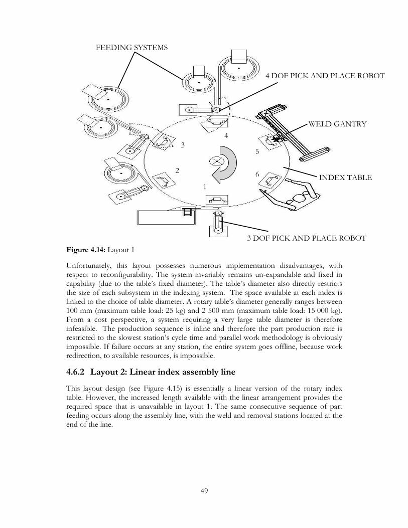
49
Figure 4.14: Layout 1
Unfortunately, this layout possesses numerous implementation disadvantages, with respect to reconfigurability. The system invariably remains un-expandable and fixed in capability (due to the table’s fixed diameter). The table’s diameter also directly restricts the size of each subsystem in the indexing system. The space available at each index is linked to the choice of table diameter. A rotary table’s diameter generally ranges between 100 mm (maximum table load: 25 kg) and 2 500 mm (maximum table load: 15 000 kg). From a cost perspective, a system requiring a very large table diameter is therefore infeasible. The production sequence is inline and therefore the part production rate is restricted to the slowest station’s cycle time and parallel work methodology is obviously impossible. If failure occurs at any station, the entire system goes offline, because work redirection, to available resources, is impossible.
4.6.2 Layout 2: Linear index assembly line
This layout design (see Figure 4.15) is essentially a linear version of the rotary index table. However, the increased length available with the linear arrangement provides the required space that is unavailable in layout 1. The same consecutive sequence of part feeding occurs along the assembly line, with the weld and removal stations located at the end of the line.
1
2
3
4
5
6
3 DOF PICK AND PLACE ROBOT
FEEDING SYSTEMS
WELD GANTRY
INDEX TABLE
4 DOF PICK AND PLACE ROBOT
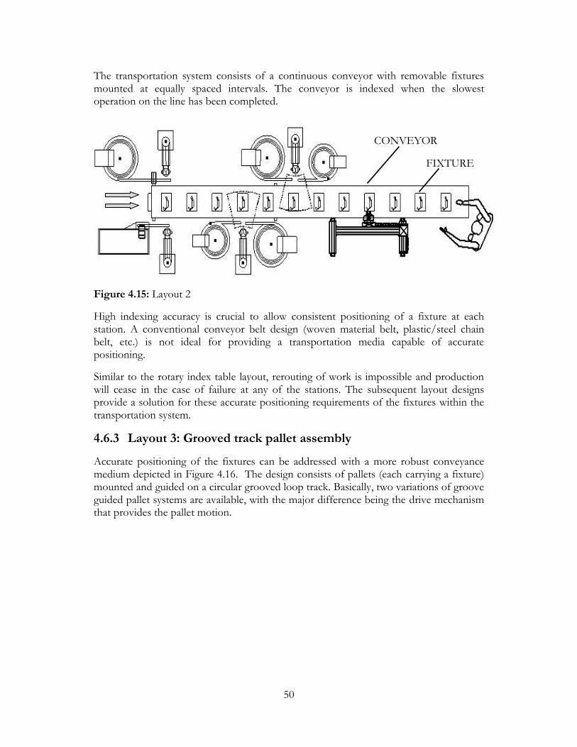
50
The transportation system consists of a continuous conveyor with removable fixtures mounted at equally spaced intervals. The conveyor is indexed when the slowest operation on the line has been completed.
Figure 4.15: Layout 2
High indexing accuracy is crucial to allow consistent positioning of a fixture at each station. A conventional conveyor belt design (woven material belt, plastic/steel chain belt, etc.) is not ideal for providing a transportation media capable of accurate positioning.
Similar to the rotary index table layout, rerouting of work is impossible and production will cease in the case of failure at any of the stations. The subsequent layout designs provide a solution for these accurate positioning requirements of the fixtures within the transportation system.
4.6.3 Layout 3: Grooved track pallet assembly
Accurate positioning of the fixtures can be addressed with a more robust conveyance medium depicted in Figure 4.16. The design consists of pallets (each carrying a fixture) mounted and guided on a circular grooved loop track. Basically, two variations of groove guided pallet systems are available, with the major difference being the drive mechanism that provides the pallet motion.
CONVEYOR
FIXTURE

51
Figure 4.16: Layout 3
The first type is driven by a linear cam mechanism (depicted in Figure 4.17). The actual system investigated was the linear assembly system LS280, developed by WEISS GmbH Sondermaschinentechnik. The pallets are mounted on a roller carriage and pulled along the grooved track between processing stations.
Once a pallet arrives at a station, it engages the linear cam mechanism via a lateral peg. The cam mechanism provides smooth, impact and vibration free movement to the pallet, with a high degree of positioning accuracy. The pallet is indexed forward through the series of processing stations located along the length of the cam.
The second type consists of a pallet, mounted on rollers, driven by a chain mechanism within a guide channel (see Figure 4.18). The actual system investigated was the ecoTrans® system, developed by ACI-ecoTec GmbH & Co. The pallets are magnetically linked to the moving chain, restricting the load capacity to 5 kg. Rollers carry the pallet on a flat, continuous, table top and all vertical processing forces are therefore transferred to the table.
PALLETS
GROOVE
LINEAR CAM
Figure 4.17: Linear assembly system LS280 cam drive mechanism (Weiss, 2007])
TRACK GROOVE

52
Figure 4.18: ecoTrans® system chain drive mechanism (Aci-ecotec, [s.a.])
An actual application example is depicted in Figure 4.16, with the groove track separating a stop module on the left and a lateral positioning module on the right. The pallet is halted at the work station by a stopper module and accurately positioned from the side, for the subsequent work process.
Figure 4.19: Actual application example: ecoTrans® system (Aci-ecotec, [s.a.])
4.6.4 Layout 4: Loose pallet assembly
This layout design (see Figure 4.20) consists of a central round robin main loop, with modular in-feed and out-feed conveyor units, allowing the implementation of parallel loops. The actual system investigated was the TS 2plus transfer system, developed by Bosch Rexroth AG.
PALLET FIXTURE
ROLLERS GUIDE CHAIN
GUIDE CHANNEL
MAGNET
TABLE

53
Figure 4.20: Layout 4
The layout can consist of any number of feed and weld loops, allowing multiple part variations to be produced on the same line. A common removal loop can be used to remove all finished products from the system, at the same location. The use of parallel loops allows production to continue, for the one part type, if a failure occurs on the other part type.
Each conveyor section consists of dual conveyor belts, running on parallel tracks, as depicted in Figure 4.21. A pallet rests freely upon the two belt sections, providing linear movement along the length of the conveyor. Removable fixtures can be mounted on the pallets.
A pallet arriving at a work station is halted above a lift position unit by a stop gate unit, while the conveyor belts continue to slide underneath the pallet. The lift position unit performs three separate functions. Firstly, locating pins accurately position the pallet via bushes situated in the under side of the pallet. Secondly, the pallet is slightly lifted from the tracks, reducing wear on the belts. Thirdly, the vertical process forces, induced upon the pallet at the work station, are carried by the lift position unit, instead of the weaker conveyor tracks.
An RFID (radio frequency identification) system provides targeted control of the pallets routing and processing steps. Data relating to the pallet’s processing and product information accompanies the workpiece via the RFID tag, as it moves through the system. This information can be accessed at various points along the system, via read/write heads mounted along side the conveyor tracks.
FEED LOOP 1 FEED LOOP 2
WELD LOOP 1 WELD LOOP 2 REMOVAL LOOP
ROUND ROBIN
PALLET

54
Figure 4.21: Conveyor tracks and lift position unit (Bosch Rexroth, 2006)
4.7 Final Concept Selection
The stated implementation restrictions of layout 1 and 2 were addressed by the more suitable and robust designs of layouts 3 and 4. The following section therefore provides the reasoning used in selecting the most suitable concept between layouts 3 and 4. For succinct purposes, the two types of versions described in layout 3 are referred to as the cam layout and the chain layout, respectively. Layout 4 is referred to as the loop layout. All three layout designs provide a feasible approach to the assembly requirements. It is the mechanical arrangement and constitutive drive systems, of each concept that provide a means to approach evaluation. The discussion therefore considers these components separately.
Both the cam and chain layout pallets are considerably more complex in design (with multiple rollers, magnets etc.). This inevitably increases the pallet’s costing and also requires a greater amount of maintenance in both cases. Furthermore, the cam layout pallets must be loosened from the guide rails when fixture replacement is necessary. The loop layout’s pallets consist of no moving parts and can be removed from the system at any point by simply lifting them off the conveyor tracks.
The use of the lift positioning units (which carry all processing forces), in the loop layout, allows the conveyor tracks to be relatively less rigid and light in design. This is not possible in the cam and chain layouts, were all processing forces must be carried by the groove track or table top on which the pallets run. The work stations in the loop and chain layouts can also be mounted or moved to any reasonable point along the length of a conveyor in the system, which is not possible with the cam layout where the work stations must be positioned along the fixed length of the cam. Although it was not verified, it is assumed for these reasons that a unit of conveyor length is considerably cheaper in the loop layout, than the other two.
Expanding or replacing a conveyor in the loop system (TS 2plus system) is aided by the fact that every segment is modular in design. In some cases, increasing the length of a
PALLET
TRACKS LIFT POSITION UNIT
CONVEYOR BELTS
RFID TAG

55
conveyor would just require replacing the parallel tracks and the length of the belts. This would be possible if the conveyor drive motor has sufficient power to cope with the increase. A similar scenario (yet more costly) is capable with the chain layout, were the chain length, guide channel length and table top length could be increased. The cam layout would require a completely new cam shaft to be machined and purchased.
In summary, the cam layout can be described as the most fixed or dedicated concept under investigation. While the chain layout provides a more attractive alternative in a grooved track system, its rolling pallet and magnetic drive system introduce unwanted complexities from a maintenance and costing perspective. Furthermore, authorised distributors for both systems could not be located within Southern Africa. Many of the standard components (belts, leg sets, etc.), used on the loop layout system, can be purchased locally. This was confirmed by the TS 2plus distributor (Rothery, 2008).
Layout 4 is therefore chosen as the final conceptual layout for further development.
56
Chapter 5
System Embodiment Design
5.1 Introduction
This chapter provides concise embodied detail, built on the final selected concept layout, which is required for further development in the detail design stage. Detail pertaining to the selected off-the-shelf hardware, for each sub-system, provides a means to properly validate the selected concept layout as a whole. The subsequent sections outline the chosen subsystem’s capabilities and interface requirements. This is addressed in such a way that the degree of subsystem flexibility and full system reconfigurability is increasingly apparent and available for further analysis in the simulation investigation presented in Chapter 6.
As discussed in Section 4.6.4, the loose pallet assembly layout (TS 2 plus transfer system) can consist of any number of feed and weld loops. Three variations of this design are presented: a single loop variation, which represents a common inline assembly arrangement, a double loop variation, which represents a parallel assembly arrangement and a triple loop variation, which represents an expanded version of the parallel assembly arrangement.
The three design variations therefore represent three common approaches in assembly line layout design and provide a basis for comparative analysis in the subsequent simulation chapter. The simulations provide invaluable data, necessary for selecting the most suitable layout variation, based on the daily production capacity required and the impact of reconfiguration during a production run.
5.2 TS 2plus Transfer System
5.2.1 Single loop layout variation (Model 1)
The single loop layout variation is depicted in Figure 5.1. The system consists of a single continuous loop, with four feed stations along the one side and the weld and removal stations on the other. This layout variation provides an important comparative benchmark when trying to justify using a system with multiple parallel loops. This layout variation is analogous to the rejected design of layout 3 (Grooved track pallet assembly), in Section 4.6.3. For succinct purposes, this variation is referred to as Model 1.
The four pick and place units are placed on the inside of the loop, with the terminal escapements of the feeders positioned on the outside of the loop and in front of the

57
respective lift position feed station. The weld gantry is placed over the weld station, with the front support legs on the inside of the loop. The removal robotic unit is placed on the outside of the loop, in front of the removal station. The loop has outer dimensions of 2 m x 1.2 m.
Figure 5.1: Single loop layout variation (Model 1)
5.2.2 Double loop layout variation (Model 2)
The double loop layout variation was introduced in Section 4.6.4 and is depicted in Figure 4.20. The system consists of two feed loops, two weld loops and a common removal loop. A central round robin connects all the loops in the system. A single breaker frame variation could be produced on the system, with both feed loops supplying the same types of parts to the pallets. Otherwise, the feed loops could supply separate parts for different frames, allowing two separate frame variations to be produced on the same system. The required floor space (footprint) of the conveyor system is 5.2 m x 1.6 m. The feed loops have outer dimensions of 2 m x 0.7 m. The weld and removal loops have dimensions of 1 m x 0.5 m. For succinct purposes, this variation is referred to as Model 2.
Technically, two Model 1 systems, working in tandem, posses similar capabilities to a single Model 2 system. The reduced conveyance distance in Model 1 will also be noticeable with a higher production rate. The fewer conveyor modules required should also reduce the cost (compared to a Model 2 system). However, each Model 1 system will need its own control system and removal station hardware, compared to the common removal station in Model 2.
REMOVE STATION
PALLET
HFA STATION
COIL STATION
MC/AR STATION
PIGTAILS STATION
WELD STATION

58
This question of whether two Model 1 systems will out-perform a single Model 2 system must be addressed on various levels, such as, the difference in production rates, the difference in system cost, the impact and sensitivity to subsystem failure, etc. The performance simulations presented in Chapter 6 are therefore invaluable in providing objective evaluation data and ultimately, a justified choice of the final system structure.
5.2.3 Triple loop layout variation (Model 3)
The triple loop layout variation is depicted in Figure 5.2. The system consists of three feed loops, three weld loops and a common removal loop. A central round robin connects all the loops in the system. For succinct purposes, this variation is referred to as Model 3. Similar to the Model 2 system, between one and three product variants could be produced on the system, at the same time. Furthermore, the question of whether three Model 1 systems will out-perform a single Model 3 system will also be addressed in the simulation section. The required floor space (footprint) of the conveyor system is 7.5 m x 1.6 m. The feed, weld and removal loop dimensions are the same as in the double loop variation.
Figure 5.2: Triple loop layout variation (Model 3)
5.2.4 Conveyor modules
Basically, four types of conveyor modules are available for system construction, as depicted in Figure 5.3: (a) general linear conveyors, (b) transverse in/out feed conveyors for implementing parallel loops, (c) 180˚/90˚ curve units and (d) parallel connection conveyor units.
The first three types are used to create the structure of a single or multi-loop system. The parallel connection conveyor allows a pallet to be transferred from one conveyor to another, parallel conveyor. This can allow a pallet, in a multi-loop system, to cross over

59
the round robin to reach the next processing station and therefore not have to travel around the full length of the central loop.
It must be noted that the inclusion of these parallel connection conveyors, along the length of the round robin, could considerably reduce the transportation cycle time of a pallet on a large multi-loop layout variation. However, these conveyor modules were omitted from the design because the increased functionality provided could not be included in the simulation models, due to the model size restrictions of the student license. The inclusion of these conveyor modules is therefore flagged as a means to improve the production rates on multi-loop systems.
The width of each conveyor module is determined by the width of the chosen pallet and the linear conveyor lengths can be a maximum 6000 mm. Five conveyance speeds are available (6, 9, 12, 15 18 m/min) with a maximum permissible load of 60 kg during accumulation per conveyor section.
Figure 5.3: TS 2plus basic conveyor modules
5.2.5 Pallets and fixtures
The pallets (see Figure 5.4) have an empty weight of 0.8 kg and consist of a composite plastic-steel construction, capable of carrying loads below 10 kg. A steel carrying plate, on the upper side of the pallet, provides rigidity and a mounting platform for the workpiece fixtures.
Polyamide pads are located on the underside of the pallet, creating wear protection between the belt and the pallet. An RFID tag (mobile data carrier) is mounted on the outside edge of the pallet. The pallet’s chosen dimensions are 160 mm × 160 mm, therefore resulting in a conveyor width of 160 mm.
(a) Linear (b) Transverse in/out (c) 180˚/90˚ curves (d) Parallel connection

60
Figure 5.4: Pallet and fixture CAD representation
5.2.5 Stop gates and lift positioning units
Pneumatic stop gates are used to stop pallets for subsequent processing or entry into a parallel loop. Proximity switches, mounted on the stop gates, are used to establish the presence of a pallet. Stop gates are also available with or without integrated shock absorbers. The adjustable damped stop gates are used in shock-sensitive cases and are claimed to reduce impact forces by up to 80%.
Both the stop gate and the lift position units are mounted on the inside of the conveyor tracks, and can be reinforced from below if processing forces exceed the permissible load of the conveyor. The positioning unit locates and positions the pallet with an accuracy of ± 0.1 mm while carrying a maximum processing force of 300 N. The pallet is also lifted approximately 2.5 mm above the conveyor tracks.
5.2.6 Mobile data units
Provision of workpiece data is available with RFID tags mounted on the pallets. A pallet arriving at a work station or conveyor junction can provide information to a read/write head, describing the type of workpiece being carried, the current production stage, the next processing step and the parameter settings required at the next processing station (such as the force, current and weld time parameters at a weld station).
The mobile data tag can be read and written to from all sides, with a transfer capacity of 64 bytes at maximum distance of 6 mm and transportation speed of 30 m/min. The memory capacity of a tag can be selected as 2 kB, 8 kB or 32 kB.
As depicted in Figure 5.5, the read/write heads, mounted throughout the system, track and control the pallet’s production status. The RFID tags are powered inductively by the read/write heads and data is read and edited as each process is completed. The processing stations can thus carry out production independently, removing the need for a traditional master control network. The read/write heads are connected directly to a
FIXTURE
ASSEMBLY
PALLET RFID TAG
CARRYING PLATE

61
field bus system as a participant and thus allow a user controller to access the workpiece data.
Figure 5.5: Decentralised data storage layout (Bosch Rexroth, 2007)
5.3 Part Manipulation
5.3.1 Pick and place modules
The placement of the parts into the fixture requires a great degree of precision. Freely programmable position control is also required to assist during reconfiguration and application changes. The programmable pick and place HP 140T unit from Weiss GmbH was therefore selected ahead of a conventional pneumatic pick and place system.
The HP140T (depicted in Figure 5.6) incorporates constant feedback on the axis positions, providing positioning precision of 0.02 mm and a repeatability accuracy of <0.01 mm. The maximum handling weight is 3 kg (gripper and workpiece). The vertical and horizontal strokes are freely programmable, with maximum strokes of 65 mm and 268 mm, respectively. With a net weight of 13 kg and installation footprint of 125×400×300 mm (W×D×H), the unit provides a compact design for integration into a larger system.
As proposed in Section 4.3.1, handling multiple part types with a single pick and place unit has the potential to reduce the system cost. The fewer handling units require less installation space (reducing the size of the feeding loops), fewer lift position units and stop gates and obviously, fewer robotic units. The two pigtails of a Q-frame can easily be handled by a single robotic unit. Handling the moving contact and arc runner on a single robotic unit however, proves to be more risky. However, the relatively low mass of both the AR and MC, together with the similar handling point thicknesses of both parts (see Figure 4.10) provides promising conditions for handling the parts on a single robotic unit. Furthermore, this multi-part handling arrangement was confirmed as a feasible solution to reducing system cost and size, by four independent robotic specialists, and was therefore chosen as the final conceptual robotic handling subsystem.
CONTROLLER 1
PALLET RFID TAG
READ/WRITE HEAD
CONTROLLER 2

62
Figure 5.6: Freely programmable HP 140T pick and place unit (Weiss, 2008)
In order to provide the 3rd DOF required for the pick and place units of the pigtails, arc runner and moving contact, a miniature pneumatic rotary module, mounted between the gripper and robotic arm, can align the gripper to the correct angle. Mounting the complete pick and place unit on a large pneumatic rotary unit provides the 4th DOF.
In both cases, the rotary units can only swing between a set range of degrees (90˚/180˚). In order to stop the rotation at a specific angle, a mechanical stop is required to halt the rotation. This is a common method employed to align a device mounted on a rotary unit. However, resetting the mechanical stops between reconfiguration increases the system down time and could introduce problems during system ramp-up if the stop mechanisms are not set accurately.
The selected gripper and robotic rotary units are Schunk’s MRU 10.2-E-2 and SRU 35.1-90-3-4, respectively. Both units are double acting, rack and pinion driven rotary modules. The gripper rotary module has a rotation angle of 180˚, while the robotic rotary module has a rotation angle of 90˚.
Various companies (Festo, Schunk, DE-STA-CO etc.) provide miniature parallel grippers. Three separate grippers were investigated in Skunk’s MPG series of grippers for small parts. Table 5.1 below summarizes each gripper’s details and serves to provide a range of grippers that are suitable for handling all the parts. Furthermore, the information provides a design envelope, required for the design of the gripper fingers that must be manufactured to handle the parts.
Table 5.1: Gripper specifications
Description MPG 20 MPG 25 MPG 32
Stroke per finger (mm) 2 3 4 Closing force (N) 28 31 65
Opening force (N) 24 28 55 Max. permitted finger length/weight (mm)/(kg) 20/0.012 25/0.02 32/0.04
Recommended workpiece weight (kg) 0.038 0.15 0.325

63
5.4 Resistance Weld Station
5.4.1 Electrode configuration
The electrodes must be mounted in a step configuration for the reasons discussed below. Employing an opposed electrode configuration is not possible due to the fact that the lift position unit engages the pallet from below, therefore restricting access for a lower electrode. A series configuration is prone to current shunting complications and produces two welds between the two parts being joined. This arrangement is therefore not recommended for this application.
Selection of the actual electrodes requires that the electrodes have a low electrical resistance, high heat conductivity and are capable of maintaining their shape at high temperatures during welding. The most common electrode materials are chrome copper (CrCu), molybdenum (Mo) and tungsten (W). The higher conductance of chrome copper electrodes sees them employed for most general weld applications involving ferrous and stainless steel parts. The lower conductance of molybdenum and tungsten electrodes sees them employed for welding copper and aluminium parts. Molybdenum and tungsten inserts are pressfitted into chrome copper base electrodes, which does not affect the current or heat generation during welding.
CBI reported that they initially used tungsten inserts on their manual stations, but this did not produce the desired results and acceptable welds. They therefore currently use molybdenum inserts.
The electrode face geometry determines the current density in the weld site and concurrently dissipates the heat during the final hold time of the weld cycle, which prevents fusion between the electrode and the part. If overheating does occur, then increasing the clamping force, electrode diameter or the electrode material (material conductivity) results in a reduction of part-electrode fusion. Alternatively, incorporating water cooling within the electrodes (which is the cooling method of the current manual weld stations) could reduce the risk of fusion.
Unfortunately, micro weld heads (discussed in the subsequent section) generally make use of air cooling and the traditional method of water cooling is not an option. Therefore, proper electrode selection in terms of maximum electrode diameter and material must be established with real world testing on a step configuration micro welding rig, with the full range of parts. This will also aid in the prototypical development of a weld fixture, capable of carrying and supporting a complete assembly, which requires multiple consecutive welds.

64
5.4.2 Mini resistance welding system
The chosen welding system forms part of Miyachi Unitek’s Thin-line™ range, which provides a considerable improvement in precision welding control, compared to the common pedestal type welders that are currently being used on the manual stations.
The system essentially consists of four separate functional units: a mini resistance weld head, a high frequency inverter weld controller, a transformer unit and a digital weld checker. The actual components and the arrangement thereof are depicted in Figure 5.7.
Figure 5.7: Mini resistance welding system arrangement (Miyachi Unitek2, [s.a.])
The weld head (model 88A/EZ) consists of two separately actuated electrode holders, each with a weld force range of 2.2 N to 89 N and maximum electrode diameters of 6.2 mm. The gap between the electrodes can be adjusted to a maximum of 44.5 mm. The entire head has a weight of 7.7 kg. Threaded holes on the back of the weld head provide a mounting point for automated weld stations. The developers claim that automated production line units can operate at speeds greater than 3600 welds per hour.
The force control system (EZ-AIR) allows the weld force to be adjusted in a single step, between weld variations. The system prevents weld over-force by independently controlling the upper and lower air chambers of the pneumatic piston, with a series of solenoid air valves. When the programmed weld force is reached, the driving air is closed off in the upper and lower chambers, within 4 ms, providing accurate force control. A compression spring provides instantaneous follow up of the piston/electrodes during fusion.
WELD HEAD
TOROIDAL COIL
DIGITAL WELD CHECKER
INVERTER POWER SUPPLY WELD TRANSFORMER
SECONDARY CABLE

65
The 5 kHz, high frequency DC inverter power supply (IPB5000A) supports four control types, “secondary cable constant current control”, “constant voltage control”, “constant power”, and “combination voltage-current control”. Up to five welding machines can be controlled with a single power supply by connecting each machine’s weld transformer to the power supply via an external transformer switch. Communication (RS-232C/RS-485) to the power supply is possible to set the weld parameters via an external device (PC/PLC). The weld current range is 40 A to 6 kA. The weld transformer (ITB-780B6), which steps-up the current from the power supply, has a rated capacity 17.4 kVA.
The digital weld checker (MM-370A) is required to maintain correct and stable weld parameters for quality control purposes. The checker allows the measurement of the weld current/voltage, weld time, applied electrode force (via external force sensor) and the displacement between electrodes. The displacement can be measured with an accuracy of 1 micron by mounting a linear position encoder on the weld head and measuring: initial part thickness, final displacement and the displacement profile. The extremely short current flow times experienced during resistance welding, requires a toroidal coil sensor (formally known as a Logowsky coil) to measure and generate time based waveform data of the current flow.
5.4.3 Welding gantry
The selected welding gantry, which carries the welding head, is depicted in Figure 5.8. The system is the camoline (Cartesian Motion building system) from Bosch Rexroth.
Figure 5.8: 4 DOF Cartesian gantry representation (Bosch Rexroth2, 2007)
The gantry consists of two X axis linear units (for structural rigidity) that are driven by a single synchronous servo motor via a connecting rod. The Y axis is carried by the two X axis modules, which in turn carries the vertical module in the Z axis. A rotational drive mechanism is mounted on the Z axis module, which in turn carries the mini weld head. The rotational drive mechanism will need to be designed or customized from an existing
X
Y
Z
θZ

66
rotary module and provide accurate rotational positioning for the alignment of the electrodes.
The X, Y and Z axis positioning modules were chosen as eLine (eCKK) linear electric ball rail guides with ball screw drives. The minimum stroke available for the eCKK units is 200 mm, which have a total weight of 2.77 kg (without the motors attached). This stroke was therefore chosen for the Y and Z axis units. The X-axis unit requires a greater stroke to position the weld head over the pallet system and to move the head offline to an automatic electrode dressing unit. This unit was therefore chosen with the next available stroke size of 320 mm, which has a weight of 3.26 kg.
The maximum permissible dynamic load capacity of all three axis units is 1 500 N (152.9 kg). This should be well above the combined mass that each axis will be required to carry. The maximum vertical force which the Y axis can carry is 405 N (41.2 kg). With the weld head weight specified as 7.7 kg, the rotational drive mechanism can be specified as having a weight sufficiently below 33.5 kg.
An automatic redressing tool is required to maintain a uniform contacting area on each electrode. The electrodes can therefore be reshaped and any material build-up removed, after a set number of welds have been performed.
An example of one such dual automatic dresser is available from Rhotec Tooling Sweden and is depicted in Figure 5.9 below.
Figure 5.9: Dual automatic electrode dresser with removable cutter units (Rotech, 2001)
A dresser normally consists of an air motor which rotates a removable cutter unit at about 200 rpm. If the two electrodes have exactly the same diameters and profiles then a single dresser unit will be sufficient. This is, however, unlikely and a dual dresser tool will be required to maintain the electrodes.
Simultaneous redressing of the two electrodes will be impossible because the gap between the electrodes will be less than the gap between each dresser. Each electrode will therefore need to be lowered and dressed independently of the other.
5.4.4 Weld paste/tape requirements
The use of welding paste and welding tape, in the current manual weld stations, was introduced in Section 3.3 as being a method to improve the weld quality between copper

67
parts. As far as could be established, the automated resistance welding systems that were investigated do not provide a means to automatically apply (or supply) a weld paste/tape. Most small part resistance welders are semi-automatic or complete manual systems, where an operator would ensure the application of any weld paste/tape.
A proposed solution for the application of the weld paste would entail a simple syringe type paste dispenser which is situated above the moving contact/arc runner loading station. The dispenser system would need to move over the MC, once it has been placed in the fixture, and deposit a measured amount of weld paste onto the welding surface of the MC. Alternatively, if there is insufficient space at the station, the pallet would need to be stopped just before the pigtail station by a stop gate to allow the application of the paste.
Automatically supplying weld tape for the coil to HFA weld proves to be a difficult requirement to meet for various reasons. Firstly, the weld operators currently use the heat generated during welding to break the rest of the tape away from the weld zone. This same technique cannot be used for the assembly system because the tape must be positioned between the two parts, therefore requiring that it be placed after the HFA has been loaded and before the coil is loaded. A small section of the tape would therefore need to be cut and placed in the weld zone of the HFA before the pallet is moved to the coil load station. Obviously the small piece of tape is at risk of moving, either when the pallet is engaged or released by the lift position units or during transportation.
A more feasible solution would be to investigate a welding paste which could be used in place of the welding tape, whilst still providing satisfactory weld quality. In this case, multiple weld paste dispenser systems, as proposed above, could therefore provide a solution for the weld paste requirements.
5.5 Quality Control Strategy
For quality control purposes, automatic assembly lines require a means to ensure that consecutive processes have been performed correctly. In this case it would require that the fixtures be tested for the presence of a part/parts after each station in a feed loop. If a part is missing, the pallet must be tagged to not receive any other parts and be rerouted back to the feed loop to resume the loading process.
This sort of sensing station normally incorporates proximity sensors to ascertain the presence of a part. A more expensive, yet more reliable, method is available with a vision system which can confirm the presence of a part within the fixture and establish if the part is in fact properly seated, located and orientated within the fixing zone. This is done by comparing the image to a master image of a properly loaded fixture. Reconfiguration of this quality control system is as simple as retrieving the corresponding master image for the current product range.

68
The inclusion of a visual inspection system, after each loading station in a feed loop, could prove to be too expensive. Alternatively, the presence of the parts could be checked with less expensive hardware, such as proximity sensors. A final visual check could then be completed on the entire loaded assembly, after the last feeding station.
The multiple loop systems have the advantage of requiring a single vision system, located on the main round robin, but situated before the first weld loop. The RFID tag of a pallet must inform the vision system of which master image to use for comparison, if multiple products are being produced on the same system. Furthermore, only pallets that are tagged as carrying parts will be inspected.
This strategy could also be employed to check pallets that are carrying parts that have already been welded. A second vision system could then be located on the main round robin, before the removal station or even in the removal loop. The image could then be used to confirm that the parts were not moved during welding or transportation and also to complete a basic check of the surface quality of the each weld (weld splash, part deformation, etc.). The results of the check could therefore be used to reject unsatisfactory assemblies or signal a technician/operator about parts that have moved and cannot be removed by the removal robot.
Unfortunately, a single vision system on the main loop, which checks all of the pallets coming from the various weld loops, will only pick-up a welding problem after a few scrap parts have been produced by the defective down-steam weld station. This can only be avoided by investing in a dedicated vision system for each of the weld loops.

69
Chapter 6
System Simulation
6.1 Introduction
Rockwell’s material handling simulation package, Arena®, was selected for its suitability in analyzing conceptual systems (as discussed in Section 2.7) and because a student license was available within the department. The Simulation models were created to investigate the designed system’s estimated production capability, capacity and sensitivity to reconfiguration.
The layout design provides the possibility of consisting of a number of feed and weld sub-loops. A major objective in the development of the simulation models was to establish comparative data for the three layout variations, therefore addressing aspects of optimal component selection and total system size, and ultimately providing a baseline for budgeting and detail design purposes.
6.2 Objectives and Optimization Requirements
The objectives and optimization requirements of the simulations are summarized below:
Obj.1 Provide a visual model for analysis, simplification and verification of the dynamic interaction of the coupled subsystems, within each model.
Obj.2 To measure sensitivity by identifying the most critical subsystems affecting the production rate.
Obj.3 Provide a means of capturing realistic randomness in each of the processing stages.
Obj.4 To investigate the required production time of a specified array of product batches (11 varying batches accumulating to 30 000 welded units).
Obj.5 Evaluate the effect of product change-over and the corresponding “down-time” experienced during each reconfiguration.
Obj.6 Evaluate the effect of multiple products being produced on the same system, at the same time.
Obj.7 Evaluate the effect of scheduled maintenance and random failure events. Opt.1 Obtain the optimal number of pallets per system layout, while maximizing
production. Opt.2 Obtain the optimal number of feed-loops, weld-loops and removal loops in
selecting the most attractive layout design.

70
6.3 Model Design
Three separate model layouts were developed to simulate the proposed layout variations introduced in the previous chapter. Figure 6.1 depicts a top view CAD representation of each model which where created for animation purposes. The blue coloured squares are the lift position units which depict the position of the relevant stations (HFA load station, coil load station, weld station, remove station etc.) within each specific loop.
MODEL 3
MODEL 1 1
MODEL 2
MODEL 3
LEGEND:
F – FEED LOOP
W – WELD LOOP
R – REMOVE LOOP
M – ROUND ROBIN
F F
F F F
R W W
R W W W
M
M
PART LOADING STATIONS
WELD STATION REMOVE STATION
Figure 6.1: Model 1, Model 2 and Model 3 (top view CAD representations)

71
A detailed discussion concerning the complete development, application and programmatic capabilities of Model 2, is available in Appendix A. Model 2 was selected for this purpose as it incorporates all elements found in the three models. However, any structural deviation (in Model 1 and 3) is duly noted to maintain comprehensiveness.
6.3.1 Processing time definition
The processing times for each of the processes (load, weld, remove) are the same for each model and are given in Table 6.1. The somewhat fast loading times were selected because the pick and place modules would be able to retrieve and position a part whilst the next pallet is arriving and locating itself in the lift position unit of the relevant station.
The slowest process in the sequence is the weld operations. The processing time represents the time required to position the weld head at each weld point and complete the respective weld. The current manual weld machines require approximately 0.8 seconds to complete a weld (clamp time + squeeze time + weld time + hold time). This was used as a basis for estimating the simulation weld time, where the five welds together require 4 seconds and another 5 seconds is provided to simulate the positioning time and the required electrode cooling time.
Each process operates on a seize-delay-release basis, with the seize time simulating the pallet being locked into the lift position unit, the delay time simulating the actual processing time and the release time simulating the pallet being placed back on the conveyor. However, these seize/release times were not specified in the data sheet of the selected lift position units. These times were therefore arbitrarily selected as 0.4 seconds for each station.
Table 6.1: Processing time definition (in seconds) for load, weld and remove processes
Process Seize Delay (triangular distr.) Release
Name Time Min Mode Max Time
Handle frame load 0.4 1.0 1.1 1.2 0.4
Coil load 0.4 1.0 1.1 1.2 0.4
Moving contact/Arc runner load 0.4 2.8 3.2 3.5 0.4
Pigtail 1/2 load 0.4 2.8 3.2 3.5 0.4
Welding process 0.4 8.5 9 9.2 0.4
Removal process 0.4 1.5 1.8 1.9 0.4
6.3.2 User defined variable values
The user defined variable inputs describe the system’s operational parameters, which represent the number of pallets present in the system, the set conveyor belt speed and the reconfiguration time between product change-over. The optimal number of pallets required for each model was calculated (see Appendix A.7) and are summarized in Table
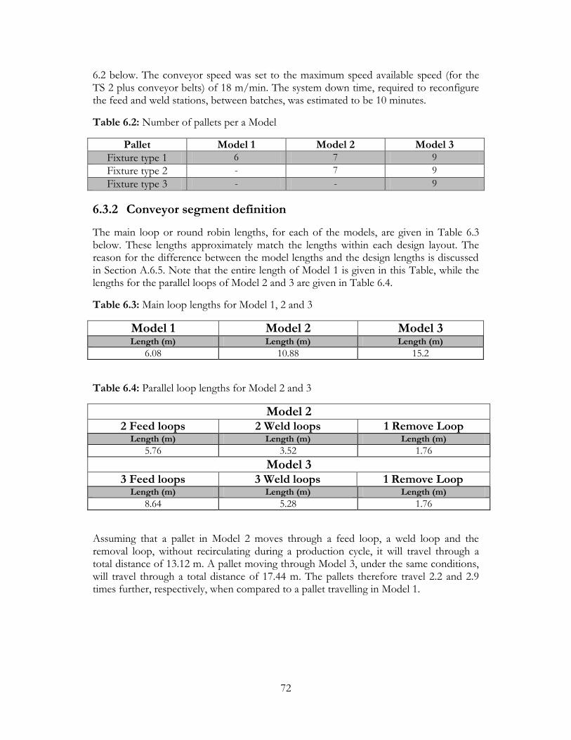
72
6.2 below. The conveyor speed was set to the maximum speed available speed (for the TS 2 plus conveyor belts) of 18 m/min. The system down time, required to reconfigure the feed and weld stations, between batches, was estimated to be 10 minutes.
Table 6.2: Number of pallets per a Model
Pallet Model 1 Model 2 Model 3
Fixture type 1 6 7 9
Fixture type 2 - 7 9
Fixture type 3 - - 9
6.3.2 Conveyor segment definition
The main loop or round robin lengths, for each of the models, are given in Table 6.3 below. These lengths approximately match the lengths within each design layout. The reason for the difference between the model lengths and the design lengths is discussed in Section A.6.5. Note that the entire length of Model 1 is given in this Table, while the lengths for the parallel loops of Model 2 and 3 are given in Table 6.4.
Table 6.3: Main loop lengths for Model 1, 2 and 3
Model 1 Model 2 Model 3
Length (m) Length (m) Length (m)
6.08 10.88 15.2
Table 6.4: Parallel loop lengths for Model 2 and 3
Model 2 2 Feed loops 2 Weld loops 1 Remove Loop
Length (m) Length (m) Length (m)
5.76 3.52 1.76
Model 3 3 Feed loops 3 Weld loops 1 Remove Loop
Length (m) Length (m) Length (m)
8.64 5.28 1.76
Assuming that a pallet in Model 2 moves through a feed loop, a weld loop and the removal loop, without recirculating during a production cycle, it will travel through a total distance of 13.12 m. A pallet moving through Model 3, under the same conditions, will travel through a total distance of 17.44 m. The pallets therefore travel 2.2 and 2.9 times further, respectively, when compared to a pallet travelling in Model 1.
73
6.3.4 Planned failure definition
The definition of planned failure occurrences, allocated to a specific resource, allows the simulation of a preventative maintenance plan. A count-based failure causes a resource to fail after a specified number of entities have used the resource. Count-based activities are common in industrial models when simulating tool replacement, cleaning, and machine adjustment. These situations are not normally regarded as “failures”, but they do occur on a periodic basis and prevent the resource from producing parts.
The planned failures represent the down time experienced when a weld head’s electrodes are dressed. A failure rule was set in the simulation such that all weld processes will be taken offline after 50 pallets have been processed (250 welds have been completed). The welder remains offline for a duration of 20 seconds which simulates the time required to position the weld head at the dressing device and then consecutively dress each electrode.
6.4 Simulation Results
A summary and discussion of the resulting data provided by the simulations is presented in this section. Firstly, the production batch distribution that was selected for each model is provided together with the corresponding time the simulation predicted it would require to complete the production run. This batch distribution represents typical production load sharing, between separate assembly lines, that is required to meet the daily production target of 30 000 units.
The production batches were distributed such that the assembly lines are loaded equally, in order to avoid a line completing its quota and standing idle for large amounts of time. The number of assembly lines required per model was estimated from the average production rate of a single line and the fact that the full production target must be met within a period of 24 hours.
It was estimated that a minimum of four single loop (Model 1) systems are required to complete the full production target of 30 000 units. The production batch distribution and corresponding production durations are depicted in Table 6.5. Lines 1, 2 and 3 are provided with equal batch targets while line 4 is provided with a smaller batch target. However, line 4 will require a total of nine reconfigurations during the production run, therefore warranting the reduced load.

74
Table 6.5: Model 1 production batch distribution
Frame Target Line 1 Line 2 Line 3 Line 4 Q1 13 200 6600 6600
Q2 5 700 1000 1000 2700 1000
Q3 2 700 2200 500
Q4 2 700 2700
Q5 1 800 1800
Q6 1 200 1200
Q7 900 900
Q8 600 600
Q9 600 600
Q10 300 300
Q11 300 300
Total 30000 7600 7600 7600 7200
Duration [hrs:min] - 20:36 20:36 20:49 20:42
Part cycle time [sec] - 9.75 9.75 9.86 10.35
It was estimated that a minimum of two double loop (Model 2) systems are required to complete the full production target of 30 000 units. The production batch distribution and corresponding production durations are given in Table 6.6.
Each line is capable of producing two separate product variants at the same time. The columns headed with Pallet 1/2 therefore represent the two separate groups of pallets (each carrying a different fixture) allocated to a certain feed loop and corresponding weld loop.
Table 6.6: Model 2 production batch distribution
Frame Target Line 1 Line 2
Pallet 1 Pallet 2 Pallet 1 Pallet 2 Q1 13 200 6600 6600
Q2 5 700 500 500 4700
Q3 2 700 2700
Q4 2 700 500 500 200 1500
Q5 1 800 1800
Q6 1 200 1200
Q7 900 900
Q8 600 600
Q9 600 600
Q10 300 300
Q11 300 300
Total 30000 7600 7600 7600 7200
Duration [hrs:min] - 23:24 23:19
Part cycle time [sec] - 5.54 5.67
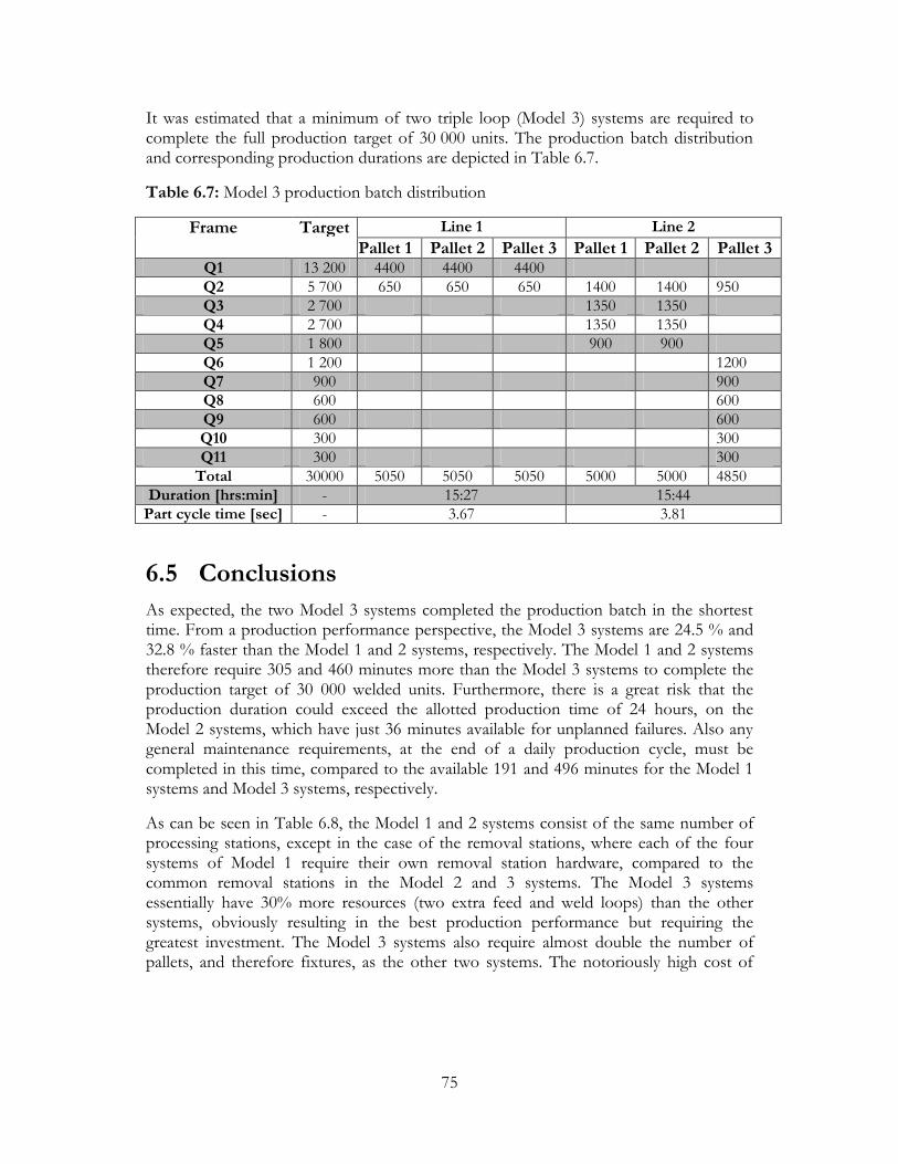
75
It was estimated that a minimum of two triple loop (Model 3) systems are required to complete the full production target of 30 000 units. The production batch distribution and corresponding production durations are depicted in Table 6.7.
Table 6.7: Model 3 production batch distribution
Frame Target Line 1 Line 2
Pallet 1 Pallet 2 Pallet 3 Pallet 1 Pallet 2 Pallet 3 Q1 13 200 4400 4400 4400
Q2 5 700 650 650 650 1400 1400 950
Q3 2 700 1350 1350
Q4 2 700 1350 1350
Q5 1 800 900 900
Q6 1 200 1200
Q7 900 900
Q8 600 600
Q9 600 600
Q10 300 300
Q11 300 300
Total 30000 5050 5050 5050 5000 5000 4850
Duration [hrs:min] - 15:27 15:44
Part cycle time [sec] - 3.67 3.81
6.5 Conclusions
As expected, the two Model 3 systems completed the production batch in the shortest time. From a production performance perspective, the Model 3 systems are 24.5 % and 32.8 % faster than the Model 1 and 2 systems, respectively. The Model 1 and 2 systems therefore require 305 and 460 minutes more than the Model 3 systems to complete the production target of 30 000 welded units. Furthermore, there is a great risk that the production duration could exceed the allotted production time of 24 hours, on the Model 2 systems, which have just 36 minutes available for unplanned failures. Also any general maintenance requirements, at the end of a daily production cycle, must be completed in this time, compared to the available 191 and 496 minutes for the Model 1 systems and Model 3 systems, respectively.
As can be seen in Table 6.8, the Model 1 and 2 systems consist of the same number of processing stations, except in the case of the removal stations, where each of the four systems of Model 1 require their own removal station hardware, compared to the common removal stations in the Model 2 and 3 systems. The Model 3 systems essentially have 30% more resources (two extra feed and weld loops) than the other systems, obviously resulting in the best production performance but requiring the greatest investment. The Model 3 systems also require almost double the number of pallets, and therefore fixtures, as the other two systems. The notoriously high cost of

76
producing fixtures therefore further undermines the feasibility of this concept from a costing perspective.
Table 6. 8: Model 1, 2 and 3 system hardware comparison
Description Model 1 (4 systems) Model 2 (2 systems) Model 3 (2 systems) Feed stations 16 16 24
Weld stations 4 4 6
Remove stations 4 2 2
Pallets/Fixtures 24 28 54
Visual inspection systems
8 4 4
As discussed in Section 5.5, the inclusion of visual quality control systems provides a means to maintain production and quality requirements. This would therefore require that each of the four systems of Model 1 be fitted with two visual inspection systems (one to inspect after feeding and one to inspect after welding). Models 2 and 3 allow common visual inspection systems to be mounted on the main loop conveyor, reducing the number of inspection systems required and therefore the overall system cost.
Bottlenecking occurs at the weld stations of all three systems, while the feed stations in each system are essentially starved or under-utilized. In order to improve production rates, a line balancing approach would require that the weld processing times be reduced in each model.
As discussed in Section 5.2.4, the inclusion of parallel connection conveyors, which allow a pallet to be moved across the main loop without having to circulate all the way around the round robin unnecessarily, would reduce the travel distance experienced by a pallet, in both of the larger systems. However, these connection conveyors would only be effective in a system where the weld stations are starved of parts to be welded. Under the current conditions, connection conveyors would simply increase the number of pallets already queuing at the weld stations.
As a measure of bottleneck sensitivity, the weld processing times of Models 1 (line 3), 2 (line 1) and 3 (Line 2) were reduced by 11%, resulting in an input triangular distribution of 7.5 : 8 : 8.2. The production duration of each model decreased to 18h:43min, 21h:13min and 14h:49min, respectively. This is an increase in production performance of approximately 10% in all three cases. Furthermore, this adjustment reduced the “intensity” of the bottleneck in each system such that the queue of pallets before the weld station is reduced to a single waiting pallet. This reduction does however require that the allotted positioning time, specified for the weld gantry, be decreased by approximately a second.
If the weld processing time cannot be reduced, for practical reasons, then the available lead time at the downstream loading processes could be allocated to processes which were not considered in the simulations, such as the application of weld paste between the relevant loading stations. Furthermore, it could be argued that the estimated loading

77
times are in fact unrealistically fast. This lead time is therefore available for expansion or adjustment of the downstream loading processes.
Implementation of parallel work methodology is dependant on the location of the bottleneck process in a system. Implementation of this design approach therefore either requires that a single process be supplied by parallel bottleneck processes or that parallel bottleneck processes be supplied by a single process. Because bottlenecking occurs at the weld stations of the models, implementation of parallel work distribution requires that a single feed loop supply two separate weld loops. This approach would be justifiable if the weld processing times were sufficiently greater (approximately 50% greater) than the loading times in the feed loops to warrant the use of parallel work distribution. This is not the case in this design, as can be seen by the weld bottleneck almost being eliminated when reducing the weld processing times by just 11%. Therefore, the two parallel weld stations would be starved of parts, resulting in under-utilization. As reported in the costing summary in Appendix B, the weld system was found to be the most expensive sub-system within the design, therefore reinforcing the requirement to eliminate under-utilization of this sub-system, as far as possible.
Perhaps a more feasible approach would be to supply three weld loops with two feed loops. This layout would be similar to a Model 2 system with an extra weld station. In order to produce two separate product types (for instance a Q1 and Q2 frame) at the same time, while utilizing all three weld loops, the product types would have to be similar enough to be welded with the same welding system configuration (same electrode setup). The RFID data system could be used to set the welding parameters required for the specific frame, when it enters the weld loop. The feasibility of this proposal lies in the verification of the flexibility of the welding system and its ability to weld multiple frames without physical reconfiguration. Actual weld testing with the chosen mini resistance weld system is therefore required to asses the possibility of welding similar frames with the same weld head. Furthermore, these tests can reveal what range of product variants are sufficiently similar to be welded on the same system.
In summary, the Model 3 systems provide the best production performance but require the greatest investment, resulting in this layout variation being infeasible. While the Model 1 systems have the second best production performance, each system is independent of the other, with each system requiring its own removal station, control system and visual inspection system. This might prove less attractive from a costing, implementation, control, and operator requirement perspective. With the Model 2 systems performing slightly below that of the Model 1 systems, the parallel loop arrangement provides little benefit other than reducing the number of secondary systems (removal stations, visual inspection system, etc.) unless parallel work distribution could be implemented, as described above. The final selection of the best layout variation must incorporate system cost estimations to provide a broader comparison basis for selection. The following chapter therefore summarizes the estimated costs involved with investing in either the Model 1 systems or Model 2 systems.

78
Chapter 7
Cost Estimation
A preliminary breakdown of the relevant subsystem costs, for each of the conceptual systems, is provided in Appendix B. The costing information provides a means to evaluate the concepts, from an economic perspective, versus the current manual costs. Furthermore, it provides a platform for the comparison of the fixture based approach versus the fixture-less approach, beyond the performance capabilities of each design.
A summary of the estimated purchase costs required to implement the Model 1 and 2 system variations is provided in Table 7.1 below. It must be noted that the estimated costs do not include the costs involved with the control hardware/software (drives, PLCs etc.) and the RFID information system (only required in Model 2 systems). Furthermore, the operating costs are assumed to be proportional to the purchase costs, as a first estimate, since the concepts all use the same technologies.
Table 7. 1: System cost comparison
Four Model 1 Systems Two Model 2 systems
Cost per system 1 634 449 Cost per system 3 437 151
Total Cost 6 537 796 Total Cost 6 874 302
As shown in Table 7.1, the four Model 1 systems are relatively cheaper (R 336 506) than the two Model 2 systems. This saving could be reduced by the fact that each of the four systems requires its own dedicated control system, which might be more expensive than the combined cost of the two Model 2 control systems. However, the Model 1 systems are “inline” and therefore do not require the RFID information system, which the Model 2 systems require to automatically route the pallets within the parallel setup.
From a reconfigurable perspective, both systems posses the flexibility required to produce a set family of breaker frames. Production beyond the primary products inevitably would require retooling or even replacement of the feeding elements, grippers, pallet fixtures, etc. in both systems.
In the case of the Model 1 systems, expanding the production capacity would require the addition of a fifth, independent line. In the case of the Model 2 systems, expanding the double loop layout to a triple loop layout (i.e. Model 3 layout) does provide a production performance increase (as seen in the results of the simulations). Adding a third Model 2 system, essentially provides a two-fold increase in extra productivity, but could result in

79
under utilization of certain subsystems, if the extra capacity is proportionally greater than the required capacity.
For these reasons (and the reasons discussed in previous chapters), the four Model 1 systems layout is chosen as the final concept for further development in the detail design stage of this project.

80
Chapter 8
Conclusions
This thesis provides a systematic conceptual design of a fixture-based, reconfigurable spot welding system for the automated assembly of the spot welding requirements for a family of circuit breakers. Secondary objectives were posed as:
Evaluating the concepts per reconfigurability/flexibility, production performance and cost
Addressing issues of economic feasibility within a developing country (Southern Africa), low cost automation and local availability
The design procedure firstly entailed the investigation of current research and industry developments, related to the constitutive subsystems of a typical automated assembly system, in Chapter 2. The literature revealed that while the notion of highly reconfigurable subsystems is promising, the added flexibility introduces complexity, interfacing issues and increases system cost. Furthermore, a separation trend is visible between automation research, focused on complex intelligent systems, and industry automation, focused on standardized, modular plug-and-play systems. Ultimately, the literature investigation highlighted the importance of selecting where to “place” the flexibility required within the system, for example, should the feeding systems be highly flexible (vision based) with a fixed manipulation system, or vise versa, etc.
The Q-frame breaker product range, assembly requirements and the current manual welding setup, introduced in Chapter 3, provided a design envelope for the chosen case study. This allowed the identification and understanding of the specific subsystem requirements and the associated automation restrictions. The subsequent concepts developed in Chapter 4 encompassed low-cost subsystems, sporting set ranges of flexibility, collectively providing a potential reconfigurable layout design.
Three separate evaluation models, each representing one of the three promising variations of the final layout design, were developed within a discrete-event driven simulation package, Arena®. The simulations, described in Chapter 6, provided insight into each system’s production performance capabilities, tolerance and sensitivity to externally driven variation in production requirements and a means to select the required number of pallets per system variation. These results, together with the estimated costs involved with each system variation, provided a comparison basis required for justifying the selection of the final system layout variation.

81
Recalling the basic definition of a RAS as: a system built from modular hardware and software units which provide customized functionality and capacity, when it is needed, reveals that the final concept does conform to the basis of this paradigm. The final concept posses the flexibility to produce the primary product range. Reconfiguration for production beyond this range is assisted by the modular nature of the layout design. This invariably is not possible with a dedicated assembly system.
The details and results of this study were presented to CBI’s management, which included production managers, design engineers and financial managers within the company. Feedback was positive and most comments or queries focused on aspects relevant to the detail design stage. Most prominent was detail pertaining to fixture design, part alignment and the welding subsystem capabilities.
The question of whether a manufacturer should invest in reconfigurable systems, in order to achieve automation cost effectively, ultimately depends on the degree of risk the manufacturer is prepared to take when selecting the variability within the primary product range. Any form of flexibility increases system cost and complexity. With the product variation known and the functional operations required within the production sequence identified, the development of a feasible solution is dictated by numerous factors but ultimately requires a balance between risk and economic feasibility.
Achievement of system reconfigurability requires the dual consideration of two connected design factors. Firstly, how should the flexibility within each subsystem be “distributed” in order to achieve a feasible reconfigurable design layout? For instance, should the feeding requirements be achieved with a few highly flexible vision-based feeding systems with articulated robots and rapid gripper change systems rather than having many dedicated bowl feeders, each with a dedicated handling robot? Secondly, are off-the-shelf systems available, which can provide this level of flexibility, or is purpose built equipment required?
Reconfigurable automation systems are also subject to the common restrictions experienced by conventional, dedicated automation systems. Firstly, Taljaard (2008) reported that a major obstacle experienced by automation engineers, is the inconsistency of the manufactured parts or defective parts. This cannot be completely accounted for during the design of the system but inevitably affect the performance of the machines. This further increases the risk associated with the chosen degree of variation of the primary product range. Secondly, the added complexity accompanying flexible equipment increases the level of difficulty and time required during subsystem interfacing and initial system ramp-up, which often requires a large portion of the allocated project time.
An often neglected and underlying problem, which is unreported by many researches studying reconfigurable systems, is that any system which is designed to be reconfigurable is still hampered by the limitations of the least flexible element of the system, and in a RAS this is usually the fixturing elements. This is analogous to a

82
conventional production line’s capacity being limited and measured by the slowest bottleneck. In this sense the reconfigurability of a RAS could be measured by the reconfigurability “bottleneck” element within the system. Solutions to this problem, such as designing a RAS to be fixtureless, only places greater constraints and limitations in efficiency, accuracy and repeatability on other sections of the systems (the robotic grippers and manipulators).
Future directions for research should entail topics such as the detail design and prototype development of flexible fixturing devices, together with real world step-configuration spot welding of the parts within these fixtures. The fixture design is critical in that the fixtures not only hold the parts but also provide a welding platform, which must be properly insulated. Furthermore, the placement and alignment of the most critical parts must be considered during the development of the fixtures, without hampering electrode access during welding.

83
Appendix A
Arena® Program Development
A typical Arena® model consists of two separate constituents:
An interconnected visual block logic (see Figure A.1) which is structurally analogous to a functional flow diagram or pseudo code, normally associated with well known programming languages.
A basic representative animation (see Figure A.2), mainly used as a means of debugging/verifying the logic.
Figure A.1: Top level logic structure for Model 2
HFA
REMOVER WELDER 4 WELDER 3
2
AR PIG COIL AR PIG COIL HFA
4 3 5 15
2 3
8
7 6 5
11 12 13 14 10 9 1
4
1 2
Figure A.2: Animation layout for Model 2 showing the 15 main loop stations

84
The development of Arena® model logic normally consists of the creation of entities1
(typically the parts within a system). Information relating to an entity is assigned to it in the form of an attribute, which can be described as variable tags.
The entities can be transported throughout the system upon different media, such as: accumulating/non-accumulating conveyors, forklifts, AGVs, etc. Global system variables are defined to monitor and alter the system’s state during a simulation. Data read/write capability is achieved by linking the model to external data files (such as Excel spreadsheets).
Two integrated steps are required to build a model. The logic blocks (decide, convey, hold, process, etc.) control entity interaction and the model condition indicators (conveyor speed, conveyor length, base time units, etc.) describe the system parameters. The following sections describe the development of Model 2, which should clarify most of the discussion above.
A.1 Create Pallets and Round Robin on Main
This sub-level (see Figure A.3) nests logic required to achieve two separate objectives; 1: Read production batch information and 2: Create two pallet types (each carrying a different fixture).
Figure A.3: Sub-level logic: create pallets and round robin on main conveyor
1 Italicized words represent Arena® specific terms.

85
In block 1 the batch target value (amount of parts to be produced), for each pallet type, is read from two separately linked Excel spreadsheets. This can be seen as the production batch distribution of products to be consecutively produced on the system.
The logic entails the creation of a single entity at the start of the simulation. It passes through the read block, retrieving the first batch value in the spreadsheet, followed by the assignment of the retrieved value to the current production target. The entity is then held at the hold block until the batch target has been met and a system reconfiguration time has elapsed. This allows the simulation of the time required to reconfigure the sub-systems (feeders, welders, etc.) for the next batch to be produced. The sequence is repeated when both conditions have been met.
Simultaneously (in block 2), two different pallet types are created at 2 second intervals (simulating an operator placing empty pallets into the system). The number of pallets created in each case is retrieved from the user defined variables: fix1 and fix2 (see Section A.6.1).
Subsequently, the pallets are assigned an assortment of attributes (simulating the pallet RFIDs reading the production information from a read/write head). These attributes are summarized and defined below:
o Assign the fixture type (f1 or f2) to the relevant pallet. o Initialize the fixture full/empty condition to zero (empty). o Initialize the weld-loop entry clearance to zero (not cleared to enter). o Assign all conveyor’s velocities to the value specified in the global variable
(convel). o Assign the access point of all created pallets to be station 1 in Figure A 2 (the
point were the worker is placing the pallets into the system). o Assign the JobStep to 1, which indicates the pallets next route station (i.e. station
1). o Assign the sequence array (seqMain) of stations (1 - 15) the pallets visit while on
the central round robin. o Assign the relevant picture to the pallets for animation purposes.
The pallets then access the main round robin conveyor, via the access block. The pallets are conveyed on the main round robin, under the action of the convey block (named: main conveyor), located in the top level logic, shown in Figure A.1. The pallets remain on the round robin until the “RFID control” releases them to the relevant sub-conveyor.
A.2 RFID Control
This sub-level (see Figure A.4) nests the system control logic. The logic is essentially divided into two functional units. Firstly, the multi-station block (main loop stations) represents all of the stations located on the main round robin conveyor. When a pallet reaches a station on the main loop, the multi-station block passes the pallet’s

86
information (attributes) to the decide module (RFID Control), which effectively routes the pallets to the proper locations (simulating the RFID routing and control network capabilities of the TS 2plus transfer system).
Figure A.4: Sub-level logic: RFID control
A reconfiguration control point/station was required to implement a state of reconfiguration (down-time) over the relevant feed and weld loops, during product change over. Station 2 was selected as the reconfiguration point because it was unused in any other part of the program (a run-time requirement of Arena®) and because it is situated after the removal loop, allowing full control from the start of the system. Every pallet arriving at station 2 on the main loop therefore triggers the decide module to test for the current state of reconfiguration (i.e. if the feed loops are “offline” or “online”).
The decide module (RFID Control) is an n-way-by-condition, if-else, logic block. A total of 19 conditions are required to achieve proper functioning and control over the routing of the pallets within Model 2. The 19 conditions are actually depicted in Figure A.4 as the lines of text below the RFID Control decide module.
The conditions can be divided into seven distinct decision categories, each related to a possible routing action when a pallet arrives at a specific station, on the main round robin loop. These categories are discussed below:

87
A.2.1 Reconfiguration control via station 2
Controlling the timing and implementation of system reconfiguration is achieved by the testing of 4 conditions when a pallet arrives at station 2, i.e. 8 of the 19 conditions (4 per pallet type) are required to implement reconfiguration control. If any of these conditions are met, the pallets are directed to the sub-sub level: reconfigure feedloop1/2, depicted at the top-centre of Figure A.4.
Condition 1: Produce the specified batch.
This condition tests the global variable, batch count (a variable used to ensure that the number of parts produced is equal to or less than target batch read in at the start of the program).
If it is less than the target batch, the pallet is directed to the assign block (Increment Batch Count), depicted in Figure A.5. This tags the pallet for entrance to the respective feed loop. The batch count variable is incremented here to track the number of pallets that have been tagged to pick-up parts within the feed loop.
Figure A.5: Sub-sub-level logic: reconfigure feedloop1
Condition 2: Calculate the future simulation time, when the system will be brought back online, after the reconfiguration time has elapsed.
This condition tests if the batch count is equal to the target batch and if the number of parts that have been welded is less than the target batch i.e. if there are still pallets, within the system, carrying parts to be welded. If true, a global variable, reconfig finish, is assigned the value of the current simulation time plus a user defined constant called, reconfig time (a value chosen to represent the time required to reconfigure the specific feed and weld loops that have completed a batch of parts). This occurs in the assign block (Assign Reconfigure Time) in Figure A.5.

88
The variable, reconfig finish, is updated in this manner by every pallet still carrying parts to be welded, with the last pallet assigning the final simulation time which will be used to bring the loops back online.
Condition 3: Take the specific feed loop offline.
This condition tests if the target batch is equal to the actual number of parts that have been welded. If true, all of the relevant pallets are tagged as “offline”, restricting them from entering the specific feed loop. This occurs in the assign block (Take Feedloop1 Offline) in Figure A.5. The pallets then round robin on the main conveyor waiting to be tagged as online again, which is achieved in the next condition.
Condition 4: Bring the specific feed and weld loops online.
This condition tests if the current simulation time is greater than the reconfigure finish time (calculated in condition 2). If true, the pallet is assigned its original state of being “online” and tagged to allow it entrance at the respective feed loop. Achievement of this condition triggers the next target batch of parts to be read from the linked spreadsheet, as described in Section A.1.
A.2.2 Feed loop entry control at stations 3 and 5
A pallet arriving at the entry station of a feed loop is tested for tags representing its “online” status, its fixture type (ensuring the correct pallet is allowed into the correct feed loop) and whether it is, in fact, empty. The “empty” tag removes the possibility of a pallet trying to enter the feed loop if it has already picked up parts. Finally, the carrying capacity of the loop conveyor is checked to ensure that there is enough space to receive the new pallet.
A.2.3 Weld loop entry control at stations 9 and 11
A pallet arriving at the entry station of a weld loop is tested for tags representing its fixture type (ensuring the correct pallet is allowed into the correct weld loop) and whether it does in fact need to be welded. The “weld” tag removes the possibility of a pallet trying to enter the weld loop if it has already been welded. Finally, the carrying capacity of the loop conveyor is checked to ensure that there is enough space to receive the new pallet.
A.2.4. Remove loop entry control at station 13
A pallet arriving at the entry station of the remove loop is tested for a tag representing whether it is carrying parts requiring removal (i.e. all pallets carrying parts that were welded in the two weld loops). Finally, the carrying capacity of the loop conveyor is checked to ensure that there is enough space to receive the new pallet.

89
A.2.5 Release pallets to main loop at exit stations 4, 6, 10, 12, and 14
A pallet arriving at the exit station of any loop is tested for a “release” tag. The tag is required to remove a run-time error of ambiguity experienced when a pallet that is travelling on the main conveyor arrives at an exit station and tries to exit onto the main conveyor, which it is already on.
If true, the pallet is directed to the sub-sub-level logic: exit specific subloop (Figure A.6 below), were the release flag is removed and the pallets access the main conveyor.
Figure A.6: Sub-sub-level logic: exit subloop
A.2.6. Reset the JobStep at station 15
The Jobstep (which is an integer value representing a pallets next sequential station to visit) must be reset to a value of 1, at the last station on the main conveyor. This occurs in the assign block (Reset Jobstep at S15) in Figure A.4.
A.2.7 Else convey on main conveyor
Finally, the else leg of the if-else decide block maintains the flow of all pallets on the main conveyor which do not qualify or test positive for any of the 19 conditions.
A.3 Feed Subloop 1
Once the pallets have been given entry clearance from RFID control, they enter the sub-level logic: feed subloop1/2 logic (Figure A.7 below). The pallets exit the main conveyor at station S3 (for feed subloop 1), access the sub loop conveyor and move to the first part pick-up station (Enter HFA load).
After accessing the station, the resource defined within the part placement process (HFA process) simulates the time required to physically lock the pallet and receive the part from the pick and place robot. The pallet is then released (and conveyed) to the next pick-up station, repeating the cycle until all the parts have been placed within the fixture. After the final two parts have been placed (the two pigtails), the pallet is tagged for release and welding, and conveyed to the exit station.

90
Figure A.7: Sub-level logic: feed subloop 1
A.4 Weld Subloop 3
Once the pallets have been given entry clearance from RFID control, they enter the sub-level logic: weld subloop3/4 (Figure A.8 below). The pallets exit at station S9 (for weld subloop 3), access the sub loop conveyor and move to the weld station (Enter Welder 3).
After accessing the station, the resource defined within the weld process (weld3 process) simulates the time required to physically lock the pallet and complete all five spot welds required per an assembly. The pallet is then tagged for release and removal, and conveyed to the exit station.
Figure A.8: Sub-level logic: weld subloop 3

91
A.5 Remove Subloop 5
Once the pallets have been given entry clearance from RFID control, they enter the part removal sub loop logic (depicted in Figure A.9). The pallets exit at station S13, access the sub loop conveyor and move to the remover station (Enter Remover 5).
After accessing the station, the resource defined within the removal process (Remove Process 5) simulates the time required to physically lock the pallet and remove the complete assembly from the pallet. The pallet type is then tested, so that the attributes of each pallet type can be individually reset in the assign modules (Empty Pallet 1/Empty Pallet 2). Here the pallets are tagged for release and as empty, and conveyed to the exit station.
Figure A.9: Sub-level logic: remove subloop 5
A.6 Model Condition Indicators
The model condition indicators allow the input of the system parameters and operational characteristics. This information completely describes the system functionality, which cannot be captured within the functional block logic. These parameters are listed and described in the following sections. The actual input values that were used in the simulations are given in Section 6.3.1-4.
A.6.1 User defined variables
o fix1: sets the number of pallets created that carry fixture type 1. o fix2: sets the number of pallets created that carry fixture type 2. o fix3: sets the number of pallets created that carry fixture type 3.

92
o convel: sets the conveyance speed of the conveyors (conveyor segment units per base time unit, see Section A.6.5).
o reconfig time f1: sets the reconfiguration time associated with feed loop 1 (minutes).
o reconfig time f2: sets the reconfiguration time associated with feed loop 2 (minutes).
o reconfig time f3: sets the reconfiguration time associated with feed loop 3 (minutes).
o batch count f1: stores the number of pallets (with fixture type 1) that have received parts from feed subloop1.
o batch count f2: stores the number of pallets (with fixture type 2) that have received parts from feed subloop2.
o batch count f3: stores the number of pallets (with fixture type 3) that have received parts from feed subloop3.
o first batch f1: stores the current target batch size, for pallet type 1, read in from the list of batch sizes in the linked Excel spreadsheet.
o first batch f2: stores the current target batch size, for pallet type 2, read in from the list of batch sizes in the linked Excel spreadsheet.
o first batch f3: stores the current target batch size, for pallet type 3, read in from the list of batch sizes in the linked Excel spreadsheet.
o reconfig finish f1: stores the calculated simulation time when feed loop 1 will be brought back online.
o reconfig finish f2: stores the calculated simulation time when feed loop 2 will be brought back online.
o reconfig finish f3: stores the calculated simulation time when feed loop 3 will be brought back online.
A.6.2 Processing time definition
Processing times must be defined to simulate the time required to place the parts into the fixtures, complete the five spot welds and remove the finished parts from the fixtures.
Each process is linked to a resource (either a pick and place robot at the feed or removal stations or a welding system at the weld stations). This allows the utilization statistics for each resource to be tallied. In all cases the processing time is defined by a triangular distribution, with the most likely processing time being the mode (apex value of the triangle) that is flanked by the minimum and maximum values. The choice of processing times can only be described as educated guesses because accurate performance data is obviously not available for any of the processing systems working with the specific parts and fixtures.
However, ensuring that the three models are subject to the same conditions is sufficient (if not realistic) in evaluating the performance of the models with respect to one another.

93
A.6.3 Sequence definition
o SeqMain: Defines the main loop sequence of stations (S1 – S15)
A.6.4 Conveyor definition
o ConMain: Defined as an accumulating conveyor, linked to segment SeqMain. o ConFeed1: Defined as an accumulating conveyor, linked to the segment
SegFeedloop1. o ConFeed2: Defined as an accumulating conveyor, linked to the segment
SegFeedloop2. o ConWeld3: Defined as an accumulating conveyor, linked to the segment
SegWeldloop3. o ConWeld4: Defined as an accumulating conveyor, linked to the segment
segWeldloop4. o ConRemove5: Defined as an accumulating conveyor, linked to the segment
SegRemoveloop5.
A.6.5 Conveyor segment definition
The segment definition for each conveyor describes the stations located on each conveyor segment and the distance between each consecutive station. In order to calculate these distances, Arena® requires the definition of the conveyor’s cell size. This is calculated by dividing the conveyor length into a series of consecutive, equal-sized cells, known as conveyor segment units. Each cell can hold only one entity (pallet). The pallet length therefore dictates the cell size chosen, with the conveyor lengths expressed in integral multiples of the pallet length. The distance between consecutive stations is therefore expressed as a multiple of these conveyor segment units.
The pallets are 0.16 m long, with a 1 m long conveyor requiring 6.25 cells. However, the number of cells within a conveyor must be an integral value (Arena® requirement), therefore requiring the 1 m conveyor to be round-off to 6 units. This introduces a slight discrepancy between the model length and the actual system length.
The simulation conveyor velocity must be calculated from the actual system velocity using the defined conveyor segment units. This is the value stored in convel. This simulation velocity is simply calculated by dividing the actual system velocity by the conveyor segment size (0.16 m). A velocity of 18 m/min is therefore calculated as 112.5 segment units/min (which must also be round off to the nearest integer value).
A.6.6 Planned failure definition
The defined failures are described below:

94
o RedressWeld3: This failure rule is linked to the resource within welder 3 station. The failure occurs after a defined number of parts have been welded, with the resource down time defined in seconds. This simulates the automatic redressing of the weld electrodes at each weld station.
o RedressWeld4: This failure rule is linked to the resource within welder 4 station.
A.6.7 Simulation replication parameters
The definition of the simulation parameters allows the user to set the number of replications, the simulation length, the termination conditions and the base time unit (sec, min, hrs, days), which affect other parameters such as the conveyor velocity (conveyor segment units per base time unit), etc.
The number of replications is set to 10. This is required to capture sufficient randomness within the system and confidently evaluate the performance, over a number of similar production runs.
The simulation length is set to infinite. Termination is achieved by defining termination conditions which are dependant on the state of the output of the simulation. Termination occurs when the complete array of batches, for all pallet types, have been produced by the system.
The base time unit is set to minutes. This was chosen due to the fact that the TS 2plus conveyor velocities are specified as 6, 12, 15 or 18 metres per minute.
A.7 Simulation Parameter Optimization
A useful add-on package for Arena® is OptQuest, developed by OpTek Systems, Inc. The software allows for the optimization of chosen model parameters.
The optimum number of pallets required per model can therefore be found by maximizing the estimated production rate, while minimizing the number of pallets that are recirculated on the main loop because there was not enough space for them to enter the feed/weld loops.
The estimated production rate is calculated with the following equation (with TNOW the current simulation time):
Furthermore, the impact of running the system at the different conveyor speeds (6, 9, 12, 15 18 m/min) also effects the optimum number of pallets required. This is important if there is a drastic difference in conveyor costs that run at the different speeds (driven by different sized motors).

95
However, after consulting with the TS 2plus system distributors, it was established that the cost difference is negligible between the conveyors. The conveyor speed parameter was therefore set to the maximum speed of 18 m/min (112 units/min) during optimization.
The results for an optimization run for Model 2 is depicted in Figure A.10. The simulation was run without reconfigurations taking place i.e. the simulation was terminated after a set number of assemblies had been produced (2 000 assemblies).
Although the software suggests that the optimum number for the two pallet types is 8 in both cases, analyzing the data more carefully reveals that very little improvement occurs over the top 8 solutions. However, considerable improvement occurs with pallet type 1 and pallet type 2 set at 7, in both cases. Therefore, a total of 14 pallets are required for a Model 2 system.
In this manner the optimum number of pallets can be calculated for the other two systems. Model 1 just has a single pallet type and the optimum number of pallets required for this system was calculated to be 6 pallets. Similar to Model 2, Model 3 requires a total of 7 pallets per fixture type or a total of 21 pallets.
Figure A.10: Optimum number of pallets for Model 2
4900
4700
5100
5200
4500
Simulation Number

96
Appendix B
Cost Estimation The following tables provide a basic overview of the costing information relating to the four Model 1 systems (Table B. 1) and the two Model 2 systems (Table B. 2).
Table B.1: Costing overview: four Model 1 systems
TS 2plus Module Modules per system Cost per system Cost per four systems Pallets 6 4 170 16 680 Fixtures (estimate) 6 7 200 28 800 Conveyor units 8 157 783 631 132 Lift position units 6 50 881 203 520 Accessories - 10 850 43 400 Subtotal - 230 884 923 532 3DOF Pick and Place Systems Schunk grippers (MPG 25) 3 8 460 33 840 Rotary gripper modules 3 11 820 47280 Accessories - 10 743 42 972 Weiss pick and place units 3 240 000 960 000 Subtotal - 271 023 1 084 092 4DOF Pick and Place Systems Schunk grippers (MPG 32) 2 5 880 23 520 Rotary gripper modules 2 7 880 31 520 Rotary robot modules 2 28 260 11 3040 Accessories - 9 898 39 592 Weiss pick and place units 2 160 000 640 000 Subtotal - 211 918 847 672 Weld Gantry System Gantry System 1 160 000 640 000 Weld System 1 465 624 1 862 496 Subtotal - 625 624 2 502 496 Feeding Systems Vibratory Bowls (Aylesbury) 5 180 000 720 000 Magazine feeder (estimate) 1 40 000 160 000 Subtotal - 220 000 880 000 Quality Control Vision system Camera (estimate) 2 40 000 160 000 Software and Installation 1 35 000 140 000 Subtotal - 75 000 300 000
Total 1 634 449 6 537 796

97
Table B.2: Costing overview: two Model 2 systems
TS 2plus Module Modules per system Cost per system Cost per two systems Pallets 14 9 730 19 460 Fixtures (estimate) 14 16 800 33 600 Conveyor units 24 656 320 1 312 640 Lift position units 11 92 620 185 240 Accessories - 19 892 39 784 Subtotal - 795 362 1 590 724 3DOF Pick and Place Systems Schunk grippers (MPG 25) 5 14 100 28 200 Rotary gripper modules 5 19 700 39 400 Accessories - 17 905 35 810 Weiss pick and place units 5 400 000 800 000 Subtotal - 451 705 903 410 4DOF Pick and Place Systems Schunk grippers (MPG 32) 4 11 760 23 520 Rotary gripper modules 4 15 760 31 520 Rotary robot modules 4 56 520 11 3040 Accessories - 19 796 39 592 Weiss pick and place units 4 320 000 640 000 Subtotal - 423 836 847 672 Weld Gantry System Gantry System 2 320 000 640 000 Weld System 2 931 248 1 862 496 Subtotal - 1 251 248 2 502 496 Feeding Systems Vibratory Bowls (Aylesbury) 10 360 000 720 000 Magazine feeder (estimate) 2 80 000 160 000 Subtotal - 440 000 880 000 Quality Control Vision system Camera (estimate) 2 40 000 80 000 Software and Installation 1 35 000 70 000 Subtotal - 75 000 150 000
Total 3 437 151 6 874 302

98
List of References
Abdi, M R and Labib, A W, 2004, Grouping and selecting products: design key of Reconfigurable Manufacturing Systems (RMS), International Journal of Production Research, vol 42, no 3, 521 – 546.
Aci-ecotec, [s.a.], ecoTrans® Flexible Work-piece Pallet Transfer, version 1.0.
Adept, 2008, [Online], Available: http://www.adept.com, [2007, December 5].
Alink, R, 2008, A case study to the possibilities of (flexible) reconfigurable feeding of parts to flexible assembly lines, Internship Report, Department of Mechanical & Mechatronical Engineering, Stellenbosch University, August 2008.
Arena, 2008, [Online], Available: www.arenasimulation.com, [2008, July 10].
Autodesk, 2008, [Online], Available: www.autodesk.com/store, [2008, July 12].
Azanpour, S, Fung J, Mills, J K, Cleghorn, W L, 2006, Flexible fixture design with applications to assembly of sheet metal automotive body parts, Assembly Automation, Vol 26, no 2, 143-153.
Bloss, R, 2006, Automated assembly of electrical panel covers, Assembly Automation, Vol 26, no 3, 192-194.
Boothroyd, G, 2005, Assembly automation and product design 2nd edition, CRC Press, Taylor and Francis Group, Florida.
Bosch Rexroth, 2006, Transfer system TS 2plus, Version 3.0.
Bosch Rexroth, 2007, RFID systems, Version 2.0.
Bosch Rexroth2, 2007, camoLINE Cartesian Motion Building System, Version 1.0.
Brauer, R, 2008, Telephonic interview, CBI-electric: low voltage, 27 October, Stellenbosch.
Causey, G C, 1999, Elements of agility in manufacturing, Ph.D. Dissertation, Department of Mechanical and Aerospace Engineering, Case Western University, January 1999.
Choi, H and Koc, M, 2006, Design and feasibility tests of a flexible gripper based on inflatable rubber pockets, International Journal of Machine Tools and Manufacture, Vol 46, 1350-1361.

99
Comtech, 2008, [Online], Available: http://www.comtechnorthamerica.com, [2008, March 8]
Cosimir Getting Started, (2001), [online], Available: http://download.mitsubishi-automation.com/resources/manuals/COSIMIR-GettingStarted%20E.pdf?form_submit=View+now, [2007, November 10].
Destaco, [s.a.], [Online], Available: http://www.destaco.com, [2007, November 15].
Dymond, F S D, expected 2009, Design of a Fixtureless Reconfigurable Automated Spot Welding Assembly System, MScEng Thesis, Department of Mechanical and Mechatronic Engineering, Stellenbosch University.
Edmondson, N F and Redford, A H, 2002, Generic flexible assembly system design, Assembly Automation, Vol 22, no 2, 139-152.
EIMaraghy, H A, 2006, Flexible and reconfigurable manufacturing systems paradigms, International Journal of Flexible Manufacturing Systems, Vol 17, 261-276.
Feldmann, K, Junker, S, Wolf, W, 2005, Innovative Mechatronic Devices for Flexible Automated Assembly Systems, Annals of the German Academic Society for production Engineering, 213-218.
Festo-didactic, 2008, [online], Available: www.festo-didactic.com, [2008, July 5].
Goldman, S L, Nagel, R N, Preiss, K, 1995, Agile Competitors and Virtual Organizations: Strategies for Enriching the Customer, Van Nostrand Reinhold, New York.
Grau, A, 2008, Personal interview, AGM Maschinenbau (Pty) Ltd, 9 September, Johannesburg.
Hargrove, S K and Kusiak, A, 1994, Computer-aided fixture design: a review, International Journal of Production Research, Vol 32, no 4, 733-753.
Heilala, J and Voho, P, 2001, Modular reconfigurable flexible final assembly systems, Assembly Automation, vol 21, no 1, 20 – 28.
Hollis, R L and Quaid A, 1995, An Architecture for Agile Assembly, Proceedings of the American Society of Precision Engineering, Austin, October 1995.
Joneja, A and Lee, N, 1998, A modular, parametric vibratory feeder: A case study for flexible assembly tools for mass customization, IIE Transactions, Vol 30, 923-931.
Koren, Y, Heisel, U, Jovane, F, Moriwaki, T, Pritschow, G, Ulsoy, G, 1999, Reconfigurable Manufacturing Systems, CIRP Annals - Manufacturing Technology, Vol 48, no2, 527-540.

100
Koren, Y, 2004, Reconfigurable Manufacturing Systems, COMA annals, Vol 1, 69 – 79.
Mehrabi, M G, Ulsoy, A G, Koren, Y, Heytler, P, 2002, Trends and perspectives in flexible and reconfigurable manufacturing systems, Journal of Intelligent Manufacturing, Vol 13, 135-146.
Miyachi Unitek, 2005, Thin-line™ Weld Heads, Version 1.0.
Miyachi Unitek, [s.a.], Fine Spot Welding general Catalogue.
Miyachi Unitek2, [s.a.], MICRO RESISTANCE WELDER, version 1.0.
Muir, P F, Rizzi, A A, Gowdy, J, 1997, Minifactory: A Precision Assembly System Adaptable to the Product Life Cycle, Proceedings of the SPIE, Vol 3203, 74-80.
Ozcelik, B, Erzincanli, F, Fendik , F, 2003, Evaluation of results of various materials using a non-contact end-effector, Industrial Robot: An International Journal, Vol 30, no 4, 363-369.
Quaid, A E, Xu, Y, Hollis, R L, 1997, Force characterization and communication of planar linear motors, IEEE ICRA Proceedings, Albuquerque, April 1997.
Quaid, A E, 1999, A Miniature Mobile Parts Feeder: Operating Principles and Simulation Results, Proceedings of the 1999 IEEE International Conference on Robotics and Automation, Detroit, May 1999.
Ramdeo, N, 2008, multiple e-mail correspondence, Aylesbury Engineering and Automation, June-August, Stellenbosch.
Rizzi, A, Gowdy, J, Hollis, R L, 1997, Agile Assembly Architecture: An Agent Based Approach to Modular Precision Assembly Systems, Proceedings of the International Conference on Robotics and Automation.
Rong, Y and Bai, Y, 1997, Automated Generation of Fixture Configuration Design, Transactions of the ASME, Vol 119, 208-219.
Rotech, 2001, [Online], Available: http://www.rotech.se/tip_dresser.htm, [2008, September 20].
Rothery, C, 2008, e-mail correspondance, Tectra Automation (Pty) Ltd, 15 september, Stellenbosch.
Scholz-Reiter, B and Freitag, M, 2007, Autonomous Processes in Assembly Systems, Annals of the CIRP, Vol 56/2/2007, 712-729.

101
Setchi, R M and Lagos, N, 2004, Reconfigurability and Reconfigurable Manufacturing Systems – State-of-the-art Review, 2nd IEEE International Conference of Industrial Informatics: Collaborative automation – one key for intelligent industrial environments, Berlin, June 2004.
Shewchuk, J P and Moodie, C L, (1998) Definition and classification of manufacturing flexibility types and measures. International Journal of Flexible Manufacturing Systems, Vol 10, no 4, 325–349.
Shirinzadeh, B, 1995, Flexible and automated workholding systems, Industrial Robot, Vol 22, no 2, 29-34.
Steyn, H and Bennion, E, 2008, Personal interview, Tectra Automation (Pty) Ltd, 9 September, Johannesburg.
Tay, M L, Chua, P S K, Sim, S K, Gao, Y, 2005, Development of a flexible and programmable parts feeding system, International Journal of Production Economics, Vol 98, 227-237.
Taljaard, T, 2008, Personal interview, Ingenior CC, 10 September, Johannesburg.
Techmatrix, 2007, RSX50 Automated resistance Spot Welder, Revision 3.0.
Viljoen, H, 2008, e-mail correspondence, Esteq Engineering, 22 july, Stellenbosch.
Weiss, 2007, Fast Cycling linear Assembly System LS 280, Version 1.0.
Weiss, 2008, Freely Programmable Pick & Place HP 140T, Version 2.0.
Wright, J R, 2005, SWOT Analysis of COSIMIR® Software, White paper, Department of industry and Technology, Millersville University of Pennsylvania, January 2005.
Yeung, B H B and Mills, J K, 2004, Design of a Six DOF Reconfigurable Gripper for Flexible Fixtureless Assembly, IEEE Transactions on Systems, Man, and Cybernetics – Part C: Applications and reviews, Vol 34, no 2, 226-235.
Yu, F, Yin, Y, Sheng, X, Chen, Z, 2003, Modelling strategies for reconfigurable assembly systems, Assembly Automation Vol 23, no 3, 266-272.
Zhang, W, 2003, Design and Implementation of Software for Resistance Welding Process Simulations, Society of Automative Engineers, Inc., 105-113.