conceptual design of a fifth generation unmanned strike
TRANSCRIPT

1
Conceptual design of a fifth generation unmanned strike
fighter
Eduardo Sepulveda,1 and Howard Smith.
2
Cranfield University, Cranfield, Bedfordshire, MK43 0AL, UK
Unmanned aircraft have significantly transformed aerial warfare through a combination of new
technologies, extended operational capabilities, and reduced risks and costs. Similarly, computational
modelling techniques have accelerated the rate of development for aircraft by being able to explore a large
number of design options from the earliest design stages, further reducing time, risks, and costs. The near
future will see the proliferation of unmanned combat aerial vehicles under a variety of roles such as
unmanned tankers, strike aircraft, and even air-to-air fighters. In this paper the GENUS aircraft design
framework is used to develop an unmanned weapons carrying platform able to partially match the
performance of 5th
generation fighters such as the Joint Strike Fighter F-35A. The vision of future joint
operations is for a single lead manned fighter to command and designate targets to its various loyal wingmen
unmanned aircraft, extending the combat capabilities and significantly multiplying force and air superiority.
I. Nomenclature
f(x) = objective function
gj(x) = inequality constraints
hk(x) = equality constraints
x = input vector
II. Introduction
The recent developments on 5th
generation stealth fighters, such as the F-35 program, has created a new demand
not only for 5th
generation aircraft, but for entire 5th
generation air forces, where advanced designs are taken full
advantage of by a highly integrated, collaborative network between air force, navy, army, and industry. It can be
argued that the defining characteristic of 5th
generation fighters, besides high degrees of stealth, is their advanced
data processing and fusion, allowing them to perform in highly contested airspace in a networked manner [1].
The new class of 5th
generation fighters allows for smoother integration of 4th
generation ‘legacy’ aircraft that
offer unique combat capabilities, as well as with the future generation of unmanned combat aerial vehicles (UCAVs)
which can serve as weapon carrying platforms and force multipliers. This is indeed the vision of future aerial
warfare as envisioned by various armed forces around the globe, as seen in Fig. 1.
Furthermore, a 5th
generation UCAV aligns with the US Air Force 2030 air superiority vision by supporting the
Penetrating Counterair (PCA) roles through an affordable and reliable platform able to engage in strike missions,
and provide data through its advanced array of sensors and highly integrated avionics systems. Furthermore, swarms
of UCAVs with limited performance and payload capabilities have been envisioned to play a significant role in the
future of aerial warfare [2].
The mission requirements appropriate for this new class of unmanned aerial vehicles include ground strike
capabilities, as well as limited supersonic air combat segments. An aircraft conceptual design analysis and
optimization framework will be employed in order to evaluate numerous design options in order to establish feasible
design solutions.
1 PhD candidate, School of Aerospace Transport and Manufacturing. AIAA Student Member
2 Professor, School of Aerospace Transport and Manufacturing. AIAA Senior Member

2
Fig. 1 F-35 with loyal wingmen UCAVs (Source: US Air Force3)
III. The GENUS aircraft design environment
The GENUS aircraft design environment is a flexible and robust aircraft conceptual design framework developed
at Cranfield University’s Aircraft Design group. GENUS consists of 9 essential, highly abstract modules and a set of
special modules to meet specific design and analysis needs, as shown in Fig. 2; this framework relies heavily on
polymorphism in order to achieve a flexible and robust aircraft design environment.
The core philosophy of the GENUS architecture is flexibility, robustness, and expandability; its name derives
from the taxonomical classification of biological organisms representing its capability to design and analyze various
aircraft species through a common framework and common analysis methodologies. The GENUS aircraft design
environment has been applied to the conceptual design of hypersonic transports, blended wing body aircraft, solar-
powered UAVs [3], supersonic business jets [4], and subsonic low-observable UCAVs [5]. A brief description of the
GENUS modules is given in the subsections below.
Fig. 2 Basic GENUS modules and interactions
A. Geometry
The geometry module consists of discrete geometrical elements divided into body components and lifting
surfaces. Simple cross sectional shapes define the various sections of a body component allowing for the
representation of basic fuselages, engine nacelles, and tail booms. Lifting surfaces are defined by sectional and
planform characteristics. An airfoil library containing NACA4, NACA5, NACA6, biconvex, and hexagonal airfoils
is available. Despite the simplicity, this module allows for great flexibility as shown in Fig. 3.
3 Still from US Air Force Research Lab promotional video “Air Force 2030 – Call to Action”

3
Fig. 3 Geometry flexibility in GENUS
B. Mission
The mission module defines the basic mission parameters such as cruise speed or Mach, cruise altitude, range,
loiter, fixed and droppable payload, maximum longitudinal and vertical acceleration factors, as well as estimated
maximum take-off mass. Additional mission requirements can be added in individual modules such as performance
and stability.
C. Propulsion Specification and Analysis
This module sets the basic engine parameters such as type, number of engines of each type, dimensions, pressure
ratios, materials, and type of fuel. Several engine types can be specified for missions that require transitional modes,
such as for high supersonic or hypersonic configurations. For turbojet engines (afterburning and nonafterburning),
turbofans, and ramjets, NASA’s open source applet EngineSim has been included [6]. This simple tool allows the
user to set an engine design point, which can then be frozen to obtain the off-design engine performance.
D. Mass Breakdown
Mass breakdown methods are design sensitive, avoiding purely statistical methods. In the case of UCAVs, this
module follows the approach recommended by Gundlach [7, chap.6], where equations for manned fighters and
unmanned vehicles are employed and modified to account for possible system differences. Other Class II methods
are also included to account for structural, and systems masses[8,9].
E. Aerodynamics
GENUS contains various aerodynamic analysis packages, allowing for low fidelity, empirical, fast calculations
up to medium fidelity potential flow solver for subsonic and supersonic speeds, like PANAIR. Flexibility and
increased fidelity levels can be included through legacy code written in other programming languages. Source codes,
C++ wrappers, and Java classes and native methods are compiled into a dynamic link library (DLL) through the
process shown in Fig. 4. Aerodynamic analysis tools currently available in GENUS include Digital DATCOM [10],
AVL [11], SHABP [12], PANAIR [13], FRICTION [14], and a modified Harris wave drag [15].
Fig. 4 Legacy code integration into GENUS through Java Native interface
F. Packaging and C.G.
This module calculates the available wing fuel tank volume, as well as the volumes of other internal components.
Landing gear sizing and load calculation is also performed in this module. Internal weapon bays are sized depending
on user-specified payload and weapon type. Internal components can be displaced in longitudinal and lateral
direction to manage clashes and interferences.

4
G. Performance
The full mission analysis is carried out in the performance module, as well as additional mission requirements
such as point performance and maneuvers. A variety of methods are available for the analysis of field performance
[16], energy optimized climb [17], various cruise segment types, descent profiles, and maneuver requirements.
This module determines if a design instance is able to comply with the basic mission and operational
requirements. Some of the main outputs from this module are total fuel required, altitude-speed-attitude profiles,
engine throttle settings, drag polar at various Mach-altitude conditions, and mass changes throughout mission
segments. Additionally, individual ‘flight conditions’ can be set in order to investigate the stability and trim
conditions.
H. Stability
Stability constraints such as static margin, maximum control effectors deflections, and CG range limit can be set
in this module. Digital DATCOM’s source code has been integrated into the stability analysis following the
procedure shown in Fig. 6. Automatic geometry and control surface format conversion between GENUS and
DATCOM formats allows the users to quickly size longitudinal and lateral control surfaces.
I. Radar Cross Section
Radar cross section (RCS) analysis forms part of the special modules, as it is not commonly used during aircraft
conceptual design. This module converts the geometry into triangulated facets, and RCS analysis is carried out
through physical-optics approximation adapted from the well-known and freely available POFACETS code [18].
Results have been verified against the original Matlab code for monostatic radar cross section of clean
configurations with perfect electric conductor materials.
J. Optimizers
GENUS includes two algorithms for multivariate design optimization. A custom made genetic algorithm can be
used to explore a large area of the design space for a given mission; results can be later refined by the robust
LSGRG2 algorithm [19]. Currently, only single objective optimization is implemented.
IV. Mission Requirements
Operational and mission requirements have been derived from the AIAA’s original subsonic unmanned strike
fighter request for proposal [20], unclassified information on the F-35 program [21,22], as well as a generic air-to-
air fighter mission [23, chap.1.11].
A conventional take-off and landing configuration is assumed. Payload capabilities have been estimated by
assuming that a single lead manned fighter can command a formation of several UCAVs. The mission is
summarized in Table 1 and Fig. 5. Performance and mass allowances are shown in Table 2.
Table 1 – Unmanned Strike Fighter Mission Profile
Phase Description
1-2 Warm up and take-off. Fuel allowance of 5 min at idle power for taxi + 1 min mil power. Take-off
distance ≤ 1500 m.
2-3 Minimum time to climb in mil power to cruise Mach and altitude (0.8M/12 km)
3-4 Subsonic cruise-climb, total range for climb and cruise is 1090 km
4-5 Descent to 250 m altitude and Mach 0.9
5-6 Low altitude subsonic ingress, total range 80 km, deliver air-to-surface payload
6-7 Low altitude subsonic egress, 80 km 0.9M/250 m
7-8 Subsonic minimum time to climb to Mach 0.8 and 9.5 km
8-9 Accelerate to Mach 1.5 and perform supersonic scape dash and combat for 50 km in mil power.
Combat includes one 360 deg, 5g sustained turn and firing 2 AIM-132.
9-10 Minimum time to climb to 12 km and Mach 0.8.
10-11 Subsonic cruise climb at Mach 0.8 and 12 km, until total range after egress is 1090 km.
11-12 Descend and land. Landing distance must be ≤ 1500 m.
Table 2 – Performance requirements
Payload Fully internal, 2 x 2000 lbs Mk 84 and 2 x AIM-132 ≈ 2030 kg
Field performance Conventional take-off and landing ≤ 1500 m
Ceiling Above 15 km
5
Supercruise 1.5M/9.5 km
Instantaneous G +7.5, 0.75M/4500 m
Specific Excess Power (1g) 120 m/s at Mach 0.8, 4.5 km altitude with 50% fuel and 2 x AIM-132
Acceleration Mach 0.8 to 1.2 in < 120 seconds at 9.5 km altitude max power
Sustained Turn Rate +5g at 1.5M/9.5 km with 25% fuel and 2 x AIM-132
Avionics Advanced sensor package, 300 kg allowance
Stealth Very low signature, 200 kg allowance
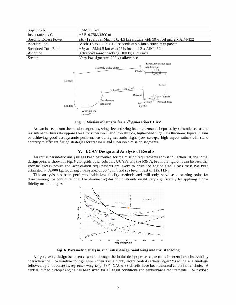
Fig. 5 Mission schematic for a 5th
generation UCAV
As can be seen from the mission segments, wing size and wing loading demands imposed by subsonic cruise and
instantaneous turn rate oppose those for supersonic, and low-altitude, high-speed flight. Furthermore, typical means
of achieving good aerodynamic performance during subsonic flight (low sweeps, high aspect ratios) will stand
contrary to efficient design strategies for transonic and supersonic mission segments.
V. UCAV Design and Analysis of Results
An initial parametric analysis has been performed for the mission requirements shown in Section III, the initial
design point is shown in Fig. 6 alongside other subsonic UCAVs and the F35-A. From the figure, it can be seen that
specific excess power and acceleration requirements are likely to drive the engine size. Gross mass has been
estimated at 18,000 kg, requiring a wing area of 50.45 m2, and sea level thrust of 125.4 kN.
This analysis has been performed with low fidelity methods and will only serve as a starting point for
dimensioning the configurations. The dominating design constraints might vary significantly by applying higher
fidelity methodologies.
Fig. 6 Parametric analysis and initial design point wing and thrust loading
A flying wing design has been assumed through the initial design process due to its inherent low observability
characteristics. The baseline configuration consists of a highly swept central section (ΛLE=72°) acting as a fuselage,
followed by a moderate sweep outer wing (ΛLE=53°). NACA 63 airfoils have been assumed as the initial choice. A
central, buried turbojet engine has been sized for all flight conditions and performance requirements. The payload

6
has been divided into two internal weapon bays. Figure 7 shows a plan view of the baseline UCAV design
superimposed on an F35-A, as well as a schematic arrangement of internal components.
The initial mass estimate has been refined through the GENUS methodologies and a significantly lower mass
was found. The resulting take-off mass is 12190 kg, with a fuel consumption of 2210 kg, and an empty mass of 7950
kg. The dominating design constraint was found to be the engine thrust requirements during the supersonic dash
segment at 9.5 km altitude, as well as sustained turn requirements at supersonic speeds.
Fig. 7 Top view comparison to F35-A4 and packaged UCAV
A. Airfoil trade-offs
The overall aerodynamic choice should reflect the subsonic, transonic, and supersonic compromise resulting
from the mission requirements. Good subsonic aerodynamic performance dictates certain geometric and airfoil
choices that will result in poor supersonic performance. The effect of typical subsonic airfoils compared to transonic
and purely supersonic airfoils are shown in terms of the mission segment fuel and drag polar plots at various
Mach/altitude conditions in Figs. 8 and 9.
While aerodynamic performance during subsonic cruise segments is very similar for all airfoils, the advantages
of supercritical and supersonic airfoils are obvious for transonic and supersonic Mach numbers. During the low-
altitude, high-speed ingress/egress segments the SC(2)-0406 supercritical airfoil reduces compressibility drag by
15% and 30% when compared to NACA631-207 and NACA2307 airfoils respectively. In the case of supersonic
flight, the supercritical airfoil matches the performance of the biconvex airfoil. In summary, choosing a supercritical
airfoil for the outer wing segment reduces the maximum take-off mass by 5.3%, and fuel by 6.5% for a leading edge
sweep angle of 53°.
Fig. 8 Effect of airfoil on mission segment fuels
4 Wikimedia Commons https://commons.wikimedia.org/wiki/File:F-35A_three-view.PNG

7
Fig. 9 Drag polar plots for subsonic, transonic, and supersonic airfoils
B. Outer Wing Sweep Angle
The leading edge sweep angle has a strong influence on aerodynamic performance, fuel consumption and engine
sizing. Also, higher sweep angles often result in higher wing masses, therefore the weight advantages and penalties
need to be accounted for to identify viable sweep angle ranges that can be later refined through multivariate
optimization. Trade-off studies for the outer wing leading edge sweep shown in Fig. 10 demonstrate that sweep
angles below 50 degrees result in aerodynamic and fuel penalties for transonic and supersonic flight segments.
Configurations with sweep angles higher than 60 degrees show that structural mass penalties outweigh the
aerodynamic advantages.
Fig. 10 Leading edge sweep effect on vehicle and component masses

8
C. Engine By-pass Ratio
Additionally, changes in by-pass ratio have been investigated for afterburning turbofans and compared to the
initial afterburning turbojet engine. Results have been normalized with respect to the original afterburning turbojet
configuration. Figure 11 shows that despite the fact that the fuel consumption decreases for by-pass ratios above 0.4,
overall vehicle masses are still higher, due to the heavier turbofan engine. However, afterburning turbofan engines
can reduce the infrared signature due to reduced plume temperatures, as well as the temperature of surrounding
structures, and should still be considered a viable option in further design stages where a more comprehensive low
observability analysis is performed.
Fig. 11 By-pass ratio effects on vehicle mass, required thrust and fuel consumption
D. Multidisciplinary Optimization
The trade-off studies shown above have been used to select some of the aircraft’s characteristics. A supercritical
airfoil SC(2)-0406 will be used for the outer wing section, along with a central buried afterburning turbojet engine.
Improved engine modelling has been adopted for the optimization results below in order to arrive at a more realistic
fuel consumption; overall engine efficiency does not exceed 60%.
Multivariate optimization will be used to find a configuration with minimum take-off mass, while also subjecting
the design to static longitudinal stability and trim during all flight conditions.
The optimization problem can be formally defined as:
Minimize: 𝑓(𝑥) Subject to:
o 𝑔𝑗(𝑥) ≤ 0 𝑓𝑜𝑟 𝑗 = 1,2, … , 𝐽 o ℎ𝑘(𝑥) = 0 𝑓𝑜𝑟 𝑘 = 1,2, … , 𝐾 o 𝑥𝑖
𝐿 ≤ 𝑥𝑖 ≤ 𝑥𝑖𝑈 𝑓𝑜𝑟 𝑖 = 1,2, … , 𝑁
Design variables, upper and lower boundaries, and design and operational constraints are given in Table 3.
Table 3 Design inputs and constraints
Input Variable Lower Bound Upper Bound
Outer wing sweep [degrees] 45 70
Outer wing span [m] 2.9 4.0
Outer wing taper ratio [-] 0.01 0.4
Fuel fraction [%] 15 40
Engine diameter [m] 0.5 1.2
Component positions [m] Component dependent
Constraint Type
Maximum take-off mass error = 0
Fuel volume ≥ Required
Fuel mass error = 0
Acceleration time ≤ Required
Specific excess power ≥ Required
Sustained turn thrust ≥ Required
Cruise segments thrust ≥ Required
Static margin(All Flight Conditions) -15%≤ kn ≥15%
Generational histories of outer wing sweep angle and maximum take-off mass, as well as mass convergence
error and fuel mass compared against engine diameter are shown in Fig. 12 below. As can be seen, the main
geometric and mass values converged after only 10 generations; however, some performance parameters were not

9
compliant at the end of the evolutionary optimization. A robust gradient based optimizer has been used to finalize
the engine size and fuel consumption.
Fig. 12 Generational history of optimization variables and convergence errors
The final vehicle characteristics consist of a maximum take-off mass of 11791 kg, a total fuel consumption of
2336 kg, and an outer wing leading edge sweep angle of 60.6° with supercritical SC(2)-0406 airfoils. The engine
consists on a buried afterburning turbojet, with a diameter of 0.84 m and a sea level thrust (dry) of 93 kN. Payload is
distributed inside fully internal twin weapon bays on the sides of the engine. A schematic top view, mass
breakdown, and a preliminary CAD are shown in Fig. 13 below. Table 3 shows a comparison between the F-35A
and the loyal wingman UCAV.
Fig. 13 a) Top view of packaged UCAV, b) mass breakdown, c) preliminary CAD
Table 3 – Comparison of F-35A and UCAV
Parameter F-35A UCAV
Total Length [m] 15.67 11.2
Wing span [m] 10.7 8.9
Wing Surface [m2] 42.7 47.73
Empty Weight [kg] 13300 7425
Maximum Take-Off Weight [kg] 31800 11790
Internal payload capacity [kg] 1820 (approx..) 2030
Maximum operating Mach 1.8 1.76
Dry Thrust (Sea Level) [kN] 125 93
Wet Thrust (Sea Level) [kN] 191 112
Mass, altitude, Mach number, and angle of attack profiles are given in Fig. 14, while fuel scheduling and static
margin throughout the mission segments are given in Fig. 15. It can be seen that the configuration is longitudinally
stable for all mission segments except for the initial climb segment. Trim analysis has been performed by assuming
elevons in the outer wing section with an inboard chord fraction of 20%.
Other control surfaces, such as leading edge maneuvering controls, belly flaps, spoilers, or airbrakes have not
been determined and will be the subject for future detailed studies.

10
Fig. 14 Mass, Mach, altitude, and angle of attack mission profiles
Fig. 15 a) Fuel scheduling and b) static margin throughout the mission
Aerodynamic results showing friction and wave drag, as well as the induced drag factor are shown in Fig.16 (a)
plotted against Mach number; subfigure (b) shows the radar cross section at various radar frequencies for a clean
geometry assuming perfect electric conductor materials; subfigures (c) and (d) show specific excess power maps at
level flight and supersonic sustained turn conditions respectively.
0
0.2
0.4
0.6
0.8
1
1.2
1.4
1.6
1.8
-2
0
2
4
6
8
10
12
14
16
0 2000 4000 6000 8000 10000
Mach
Nu
mb
er
Alt
itu
de[
km
]/M
ass
[Ton
]/A
ngle
of
Att
ack
[deg
]
Time [s]
Altitude Alpha
Mass Mach

11
Fig. 16 a) Friction and wave drag and induced drag factor, b) RCS at various frequencies, c) Ps map at
level flight conditions, and d) Ps map at sustained turn flight conditions
E. Future studies
Following the conceptual design studies shown thus far, preliminary design studies will be carried out in order to
establish a baseline structural concept, initial systems architecture, and engine inlet and exhaust geometries.
Preliminary studies will be complemented with more comprehensive low observability studies which will include
multi-static radar cross section signatures at various frequencies and radar absorbent materials, as well as an initial
estimate of infrared signature. Furthermore, maneuverability levels will be enhanced through the adoption of
additional control surfaces and thrust vectoring.
VI. Conclusion
This study introduced the GENUS aircraft conceptual design environment applied to Unmanned Combat Aerial
Vehicles, specifically for the mission of a 5th
generation unmanned strike fighter designed to operate as loyal
wingmen to a manned fighter such as the F-35A, especially during first day of war operations where they can act as
force multipliers reducing the risk to human operators.
An initial parametric analysis was performed and refined through the GENUS framework for a double delta, low
observable flying wing. Initial trade-off studies were carried out in order to evaluate the effects of outer wing sweep,
taper ratio, choice of airfoil, and engine bypass ratio for afterburning turbofans. Results favor the use of supercritical
airfoils and an afterburning turbojet engine due to its lower mass. Engine choice can be revised in order to improve
infrared signature.
An evolutionary optimization algorithm has been employed to establish the main geometrical characteristics, as
well as to size and locate the internal components in order to comply with longitudinal stability constraints. Results
show that acceptable stability levels can be achieved regardless of fuel scheduling procedures. Trim analysis has
been carried out by assuming elevons in the outer wing trailing edge section with a chord fraction of 20%, which
were found to comply with deflection requirements at all flight conditions.

12
Radar cross section results show that the clean geometry configuration with perfect electric conductor materials
has acceptable levels of low observability, especially from the nose-on and tail angle views. Finally, specific excess
power maps show that there is sufficient thrust during subsonic and supersonic maneuvers.
Finally, future preliminary studies of this aircraft include detailed structural and systems layout, engine inlet and
exhaust system design, low observability studies including infrared signature, and multirole performance evaluation.
Acknowledgments
The authors would like to thank Mr. Yicheng Sun and Dr. D. Sziroczak for their contributions to the GENUS
framework. E.S. author would also like to thank the Mexican Council of Science and Technology (CONACYT) for
the financial support through the Institute of Innovation and Technology Transfer (I2T2) of Nuevo Leon.
References
1. Adamson A., Snyder M. The challenge of fifth-generation transformation. The Rusi Journal. 2017; 162(4): 60–66.
Available at: DOI:10.1080/03071847.2017.1353256
2. Stillion J. Trends in air-to-air combat: Implications for future air superiority. Center for Strategic and Budgetary
Assessments; 2015.
3. Smith H., Sziroczák D., Abbe G., Okonkwo P. The GENUS Aircraft Conceptual Design Environment. Proceedings of
the Institution of Mechanical Engineers, Part G: Journal of Aerospace Engineering. (to be published); 2018;
4. Sun Y., Smith H. Supersonic Business Jet Conceptual Design in a Multidisciplinary Design Analysis Optimization
Environment. AIAA/ASCE/AHS/ASC Structures, Structural Dynamics, and Materials Conference. 8-12 January.
Kissimmee, Florida. Reston, VA: AIAA; 2018. Available at: DOI:10.2514/62018-1651
5. Sepulveda E., Smith H., Sziroczák D. Multidisciplinary analysis of subsonic stealth unmanned combat aerial vehicles.
CEAS Aeronautical Journal. 2018; Available at: DOI:10.1007/s13272-018-0325-0
6. NASA Glenn Research Center. EngineSim Version 1.8a. EngineSim. 2015. Available at:
https://www.grc.nasa.gov/WWW/k-12/airplane/ngnsim.html (Accessed: 23 June 2017)
7. Gundlach J. Designing Unmanned Aircraft Systems - A Comprehensive Approach. 1st edn. Reston, VA: American
Institute of Aeronautics and Astronautics; 2012.
8. Howe D. Aircraft Conceptual Design Synthesis. London: Professional Engineering Publishing Limited; 2000.
9. Roskam J. Airplane Design Part V: Component Weight Estimation. Airplane Design. Roskam Aviation and Engineering
Corporation; 1985.
10. Carmichael R. Digital DATCOM. Public Domain Aeronautical Software (PDAS). 2017. Available at:
http://www.pdas.com/datcom.html
11. MIT. AVL. AVL Overview. 2017. Available at: http://web.mit.edu/drela/Public/web/avl/
12. Carmichael R. Hypersonic Arbitrary Body Program. Public Domain Aeronautical Software (PDAS). 2013. Available at:
http://www.pdas.com/hyper.html
13. Carmichael R. PANAIR. Public Domain Aeronautical Software (PDAS). 2015. Available at:
http://www.pdas.com/panair.html (Accessed: 24 April 2017)
14. Virginia Tech. Program FRICTION. Available at: http://www.dept.aoe.vt.edu/~mason/Mason_f/FRICTman.pdf
15. Harris RV. J. An Analysis and Correlation of Aircraft Wave Drag, NASA TM X-947. Langley, Virginia; March 1964.
16. Lynn S., Pete M. takeoff2.c. Blacksburg, VA: Virginia Tech; 1994. Available at:
http://www.dept.aoe.vt.edu/~mason/Mason_f/MRsoft.html#TakeOff

13
17. ESDU. Energy Height method for flight path optimisation - ESDU 91016. September 1991.
18. Chatzigeorgiadis F. Development of Code for a Physical Optics Radar Cross Section Prediction and Analysis
Application. Naval Postgraduate School; 2004.
19. Smith S., Lasdon L. Solving large sparse nonlinear programs using GRG. ORSA J. Comput. 1992; 4: 1–15.
20. AIAA. Draft from the AIAA Unmanned Strike Fighter RFP for AIAA Team Student Design Competition. Available at:
http://www.dept.aoe.vt.edu/~mason/Mason_f/SD1RFP.pdf
21. US Department of Defense. Selected Acquisition Report (SAR) - F-35 Lightning II Joint Strike Fighter (JSF) Program
(F-35). Arlington, VA; 2016.
22. O’Bryan S. F-35 Lightning II: Redifining the Multi-Role Fighter. Lockheed Martin Aeronautics Company; 2009.
23. Mattingly JD., Heiser WH., Pratt DT. Aircraft Engine Design. 2nd edn. Reston, VA: American Institute of Aeronautics
and Astronautics; 2002. Available at: DOI:10.2514/4.861444