concept study of 20 mw high- speed permanent magnet
TRANSCRIPT

The department of Electrical Engineering of the Eindhoven University of Technology disclaims any responsibility for the contents of this report
Electromechanics & Power Electronics Department of Electrical Engineering Den Dolech 2, 5612 AZ Eindhoven P.O. Box 513, 5600 MB Eindhoven The Netherlands w3.ele.tue.nl/epe/
Author: Dipl. Eng. M.D. Bogomolov TU/e supervisors: Dr. J.J.H. Paulides Dr. A. Borisavljevic Prof. dr. E.A. Lomonova Date 22.01.2013
Concept study of 20 MW high-
speed permanent magnet synchronous motor for marine
propulsion

A catalogue record is available from the Eindhoven University of Technology Library ISBN: 978-90-444-1191-1 (Eindverslagen Stan Ackermans Instituut ; 2013/009)

Abstract
High-speed permanent magnet synchronous machines are of great interest in the appli-cations where high utilization factor and eciency are required. Depending on appli-cation, power requirements change from kilowatts to megawatts. To investigate powerlimits of high-speed machines, the present feasibility study focuses on a 20 megawatt(MW) electric drive for marine propulsion. However, in addition alternative propulsionsystems, ranging 100 kW to 20 MW, have been considered in an attempt to highlightsome of the scaling rules that are apparent to high-speed machine considering theirspecic power level.
In marine propulsion, the electric drive has to provide high torque at low speed to thepropeller, however at dierent levels due to pole towing or open water operation. Forelectric drives, this tends to require high frequencies (large number of poles) as wellas high currents. In general, ocean-going ships exist to provide aordable transportfor cargo or passengers. In this respect, there exists a range of speeds within whichvirtually all ocean-going ships have operated and still operate. Within this range ofspeeds, roughly 10-30 knots, ship propulsion speed, in revolutions-per-minute (rpm), liewithin a certain range, up to a couple of hundred rpm. The horsepower range coupledwith propulsion rpm makes ship propulsion motor applications a high-torque, slow-speed electric drive. To deliver 20 MW propulsion power at a rotational speed of 150rpm requires almost 1,300,000 newton meter (Nm) of torque. Emerging ship designsthat employ dierent propulsion, e.g. water jets, may change this. However, in thefollowing decades, ship propulsion motors will remain to be dominated by high torque,slow-speed motors, which are likely to remain for quite some time yet. In this respect,state-of-the-art ship propulsion motors are almost entirely alternating current (AC)synchronous wound eld water cooled motors, or AC asynchronous induction motors.
This report aims to give a general introduction to the concept of electrically-propelledvessels and presents specically a feasibility study to a 20 MW high-speed permanentmagnet synchronous motor (PMSM) to be used for ship propulsion. Although thatalso an initial attempt is documented to provide scaling laws for high-speed PM motorranging from 100 kW to 20 MW. The purpose of this report constitutes a concept studyand not an in-depth system analysis that would be required when implementing thistechnology for an electrical drive in future propulsion systems, such as ships or largevehicles. However, special attention is given to the apparent design challenges for theselarge high speed electric drives and their possible solutions.
1

Acknowledgments
My rst words of thanks I would like to address to the Chair of Electromechanicsand Power Electronics Group at TU/e, prof. Dr. Elena Lomonova, for her guidance,constant support and encouragement during my PDEng training. I am also deeplygrateful to her for the opportunity to work on this project.
I would like to thank the Director of Postmaster Designer Program SAI-ICT, prof.Dr.-Ing. Leon Kaufmann for the possibility to perform my two year PDEng training.
I want to express my gratitude to my supervisors, Dr. Johan Paulides and Dr. Alexan-dar Borisavljevic for their thoughtful guidance and valuable advices during the courseof research. I would also like to acknowledge Dr. Frans Thoolen from CCM B.V.1
and prof. Dr. ir. Tom van Terwisga from MARIN2 for sharing their knowledge andexperience in the elds of mechanical and marine engineering.
I am indebted to my beloved family and, especially, to my dear Sasha for their support,understanding and believe in me.
1CCM, which stands for Centre for Concepts in Mechatronics, is a company located in Nuenen, theNetherlands.
2MARIN stands for Maritime Research Institute Netherlands. Location of MARIN is Wageningen,the Netherlands.
2

Contents
Abstract 1
Acknowledgments 2
List of Symbols 6
Acronyms 9
List of Figures 11
List of Tables 13
1 Introduction 14
1.1 Motivations and objectives . . . . . . . . . . . . . . . . . . . . . . . . . 14
1.2 Contribution to the company and society . . . . . . . . . . . . . . . . . 15
1.3 Strategy . . . . . . . . . . . . . . . . . . . . . . . . . . . . . . . . . . . 16
1.4 Report outline . . . . . . . . . . . . . . . . . . . . . . . . . . . . . . . . 17
2 Introduction to the Electrical Marine Propulsion 18
2.1 Advantages of electrical propulsion . . . . . . . . . . . . . . . . . . . . 18
2.2 Fuel consumption and power eciency . . . . . . . . . . . . . . . . . . 19
2.3 Vessel payload . . . . . . . . . . . . . . . . . . . . . . . . . . . . . . . . 21
2.4 Electrical propulsion for naval applications . . . . . . . . . . . . . . . . 22
2.5 Electrical propulsion architecture . . . . . . . . . . . . . . . . . . . . . 24
2.6 Ship power system design . . . . . . . . . . . . . . . . . . . . . . . . . 24
2.6.1 Vessel power-speed relationship . . . . . . . . . . . . . . . . . . 24
2.6.2 Auxiliary electrical load . . . . . . . . . . . . . . . . . . . . . . 25
2.6.3 Prime movers and generator set . . . . . . . . . . . . . . . . . . 26
2.6.4 Ship power distribution . . . . . . . . . . . . . . . . . . . . . . . 26
3

2.6.5 Variable speed drives and motors . . . . . . . . . . . . . . . . . 27
2.6.6 Power and propulsion management system . . . . . . . . . . . . 27
2.7 Types of electrical propulsion . . . . . . . . . . . . . . . . . . . . . . . 27
3 Electrical Motors used for Marine Propulsion 29
3.1 Propulsion electrical drive conguration . . . . . . . . . . . . . . . . . . 29
3.2 High-speed electrical machines . . . . . . . . . . . . . . . . . . . . . . . 30
3.3 Power electronics . . . . . . . . . . . . . . . . . . . . . . . . . . . . . . 30
3.4 Electrical motors for marine propulsion . . . . . . . . . . . . . . . . . . 30
3.4.1 Induction motors . . . . . . . . . . . . . . . . . . . . . . . . . . 31
3.4.2 Wound-eld synchronous motors . . . . . . . . . . . . . . . . . 31
3.4.3 High-temperature superconducting motors . . . . . . . . . . . . 32
3.4.4 Permanent magnet synchronous motor . . . . . . . . . . . . . . 32
3.5 Conclusion . . . . . . . . . . . . . . . . . . . . . . . . . . . . . . . . . . 34
4 Preliminary Machine Sizing 35
4.1 20 MW high-speed PMSM: design challenges overview . . . . . . . . . 36
4.2 Rotor diameter, mass and rotational speed . . . . . . . . . . . . . . . . 36
4.3 Electrical machine design . . . . . . . . . . . . . . . . . . . . . . . . . . 39
4.4 Design variables . . . . . . . . . . . . . . . . . . . . . . . . . . . . . . . 40
4.4.1 Magnetic loading . . . . . . . . . . . . . . . . . . . . . . . . . . 40
4.4.2 Current loading . . . . . . . . . . . . . . . . . . . . . . . . . . . 44
4.4.3 Reactance . . . . . . . . . . . . . . . . . . . . . . . . . . . . . . 48
4.5 Gear . . . . . . . . . . . . . . . . . . . . . . . . . . . . . . . . . . . . . 49
4.5.1 Assessment of gearbox mass . . . . . . . . . . . . . . . . . . . . 49
4.5.2 Mechanical gearbox design . . . . . . . . . . . . . . . . . . . . . 51
4.5.3 Magnetic gear . . . . . . . . . . . . . . . . . . . . . . . . . . . . 53
4.6 Conclusion . . . . . . . . . . . . . . . . . . . . . . . . . . . . . . . . . . 54
5 Down-Scaling Machine Power Rating. 60
5.1 Geometry of the machine with less power . . . . . . . . . . . . . . . . . 60
5.2 Conclusion . . . . . . . . . . . . . . . . . . . . . . . . . . . . . . . . . . 63
6 Application of High-Speed Motors on Vessels 67
6.1 Propeller basics . . . . . . . . . . . . . . . . . . . . . . . . . . . . . . . 67
6.2 Supercavitating propellers . . . . . . . . . . . . . . . . . . . . . . . . . 69
6.3 Water jet . . . . . . . . . . . . . . . . . . . . . . . . . . . . . . . . . . 70
4

7 Conclusions and Future Work 72
Bibliography 74
A Baseline Document 78
5

List of Symbols
Symbol Unit Description
A [A/m] Peak value of the fundamental wave of electric loading
Ad [m2] Heat dissipation area
B [T] Peak value of the fundamental wave of magnetic ux density
D [m] Pitch circle diameter
Dr [m] Rotor diameter
D1 [m] Diameter of the driving gear
D2 [m] Diameter of the driven gear
δeff [m] Eective air gap length
DP [m] Gear diametrical pitch
E - Young's modulus
F [m] Gear facewidth
g [m] Air gap length
I [A] Current
I [m2] Second moment of inertia
k - Safety factor
kw - Winding factor
L [H] Phase self-inductance
6

l [m] Length of the bar
lmax [m] Maximal rotor length
L [H] Synchronous inductance
ls [m] Rotor length
λ [W/(m·K)] Thermal conductivity
µ0 [Wb/(A·m)] Permability of vacuum
M [H] Mutual inductance
m - Coeecient dening heat dissipation area
n [Hz] Rotational speed
nmax [Hz] Maximum rated speed
Na - Number of teeth on a ring gear
nl [Hz] Rotational speed of a carrier
Np - Number of teeth on a planet gear
np [Hz] Gear rotational speed
Ns - Number of teeth on a sun gear
ns [Hz] Rotational speed of a sun gear
P [W] Power
P [N/m2] Pressure
p - Number of pole pairs
Pcu [W] Copper losses
Pmax [W] Maximum rated power
Pm [W] Cylinder internal pressure
Qs - Number of slots
7

ρ [kg/m3] Material density
Ri [m] Inner radius
Rth [(m2·K)/W] Thermal resistance
S [m2] Area of the cylinder cross-section
σ [N/m2] Shear stress
σh [N/m2] Hoop stress
σmax [N/m2] Maximal stress
σm [N/m2] Stress caused by magnet pressure
σs [N/m2] Stress caused by rotation
σtot [N/m2] Total stress
σT [N/m2] Stress caused by thermal expansion
T [N·m] Electromagnetic torque
t [m] Thickness of the cylinder
τp [m] Pole pitch
Θ [K] Average temperature change
Vr [m3] Rotor volume
w [rad/s] Angular speed
w [m] Width of the bar
wm [rad/s] Machine mechanical angular speed
w1 [rad/s] Angular speed of the driving gear
w2 [rad/s] Angular speed of the driven gear
Xd [Ohm] d-axis reactance
Xq [Ohm] q-axis reactance
8

Acronyms
Acronym Description
AC Alternative current
AIM Advanced induction motor
CAD Computer-aided design
CPP Controllable pitch propellers
DC Direct current
EMF Electromotive force
EPS Electric propulsion system
FEM Finite-element method
FPP Fixed pitch propellers
HTSC High temperature superconducting
ICE Internal combustion engine
IGBT Insulated-gate bipolar transistor
IM Induction motor
IMO International marine organization
IPS Integrated power system
LNG Liquied natural gas
MCR Maximal continuous rate
9

POD Propulsion with outboard drives
PM Permanent magnet
PMS Power management system
PMSM Permanent magnet synchronous motor
PWM-VSI Pulse-width modulation voltage source inverter
rpm Rotations per minute
SC Supercavitating
SFOC Specied fuel oil consumption
WFSM Wound eld synchronous motor
10

List of Figures
1.1 Project strategy . . . . . . . . . . . . . . . . . . . . . . . . . . . . . . . 17
2.1 IMO exhaust emission regulations . . . . . . . . . . . . . . . . . . . . . 19
2.2 Power losses of an electrical propulsion system . . . . . . . . . . . . . . 20
2.3 Layouts of mechanical (A), electrical (B) and electrical podded (C) propul-sion systems . . . . . . . . . . . . . . . . . . . . . . . . . . . . . . . . . 20
2.4 Diesel engine eciency in the dierent power modes . . . . . . . . . . . 21
2.5 Dierent modes of engine operation . . . . . . . . . . . . . . . . . . . . 22
2.6 Average power to mass ratio comparison . . . . . . . . . . . . . . . . . 23
2.7 Typical ship power system architecture . . . . . . . . . . . . . . . . . . 25
2.8 General dependence between ship speed and propulsion power . . . . . 26
2.9 Examples of marine propulsion units . . . . . . . . . . . . . . . . . . . 28
3.1 Comparison of eciencies of PM and induction megawatt machines . . 33
4.1 Layout of PM motor with surface-mounted magnets and carbon sleeve . 35
4.2 Power and speed ratings of "commercially" produced motors . . . . . . 38
4.3 Results of design calculations of 20 MW motor with 1.5 m rotor diameterand 50 kN/m2 shear stress a) Rotor mass versus rotational speed b) Rotormass versus rotor diameter . . . . . . . . . . . . . . . . . . . . . . . . . 39
4.4 Rotor maximum length versus diameter given for the dierent speeds . 42
4.5 Calculated magnet height versus a) Sleeve thickness b) Flux density . . 44
4.6 Calculation results of 20 MW PM design: a) Normalized magnet heightversus normalized magnet density b) Optimal sleeve thickness versusrotational speed . . . . . . . . . . . . . . . . . . . . . . . . . . . . . . . 45
4.7 Calculation results of 20 MW PM design: a) Optimal magnet heightversus rotational speed b) Normalized ux density versus rotational speed 45
4.8 Calculated ux density versus magnet height for dierent rated speed of20 MW PM motor . . . . . . . . . . . . . . . . . . . . . . . . . . . . . 46
11

4.9 Calculated number of slots: a)Winding factor b)Percentage of unoccu-pied slot space due to the geometrical restrictions . . . . . . . . . . . . 47
4.10 Calculated slot bottom diameter versus number of slots . . . . . . . . . 48
4.11 Sketch of a typical epicyclic gearbox . . . . . . . . . . . . . . . . . . . . 50
4.12 Gearbox mass versus input torque . . . . . . . . . . . . . . . . . . . . . 50
4.13 Sketch of the two-stage compound 20 MW gearbox with gear ratio 1:66and input speed of 10,000 rpm . . . . . . . . . . . . . . . . . . . . . . . 53
4.14 Coaxial magnetic gear . . . . . . . . . . . . . . . . . . . . . . . . . . . 54
6.1 POD conguration with two propellers, rotating at dierent speeds . . 68
6.2 Interdependence between craft speed, propeller speed and craft displace-ment . . . . . . . . . . . . . . . . . . . . . . . . . . . . . . . . . . . . . 70
6.3 X-ray view of a water jet, produced by Wartsilla . . . . . . . . . . . . . 71
6.4 Sketch of a water jet with direct-drive high-speed electrical motor . . . 71
6.5 Sketch of a water track . . . . . . . . . . . . . . . . . . . . . . . . . . . 71
A.1 Gannt chart . . . . . . . . . . . . . . . . . . . . . . . . . . . . . . . . . 87
12

List of Tables
3.1 Brief comparison of the motors to be used for ship propulsion . . . . . 33
4.1 Main electrical machine design variables . . . . . . . . . . . . . . . . . 41
4.2 Geometry and winding data of 20 MW motor . . . . . . . . . . . . . . 56
4.3 Load data of 20 MW motor . . . . . . . . . . . . . . . . . . . . . . . . 57
4.4 Mass data of 20 MW motor . . . . . . . . . . . . . . . . . . . . . . . . 58
4.5 Gearbox input parameters . . . . . . . . . . . . . . . . . . . . . . . . . 58
4.6 Gearbox design parameters . . . . . . . . . . . . . . . . . . . . . . . . . 59
5.1 Comparison between machines with dierent rated power . . . . . . . . 62
5.2 Geometry and winding data of 100 kW motor . . . . . . . . . . . . . . 64
5.3 Load data of 100 kW motor . . . . . . . . . . . . . . . . . . . . . . . . 65
5.4 Mass data of 100 kW motor . . . . . . . . . . . . . . . . . . . . . . . . 66
6.1 Typical top speeds of dierent types of vessels . . . . . . . . . . . . . . 69
A.1 Overview of time/capacity . . . . . . . . . . . . . . . . . . . . . . . . . 83
A.2 List of activities performed to ensure quality in dierent phases . . . . 84
A.3 Information exchange in dierent phases . . . . . . . . . . . . . . . . . 85
A.4 List of risks . . . . . . . . . . . . . . . . . . . . . . . . . . . . . . . . . 85
13

Chapter 1
Introduction
The main driving factors for electrical marine propulsion units are low mass and vol-ume, low noise and vibration, and reliability. Numerous research studies have beenconducted on various electrical motors for marine propulsion, mainly AC synchronous(wound eld), AC induction motors, superconducting motors, radial and axial perma-nent magnet motors, and some on transverse ux permanent magnet motors. All theseadvanced motor technologies, to be widely applied to oceangoing ships, must, though,become cost competitive and reliable with the presently extremely reliable and durablepropulsion technologies. On strictly a motor-to-motor or motor-to-ICE (Internal Com-bustion Engine) comparison, the advanced motor technologies should be 50-75% lessmassive and occupy 20-70% less volume than the state-of-the-art motors. This wouldprovide worthwhile improvements at the ship's power system level.
1.1 Motivations and objectives
Electrical propulsion (EP) in marine sector is a technology that has been under devel-opment for decades. However, only recently it was proven by empirical data, based onshipowner's experience, that exisitng on- and outboard electrical drives can bring sig-nicant benets, particulary in the terms of fuel savings. The advantages of electricalpropulsion systems have encouraged electrical machine manufacturers to draw a con-siderable attention to the marine industry. A brief market research gives a clear insightinto the intensity of the EP implementation. For the last decade a great number ofthe multimillion contracts have been signed between shipbuilders and electrical powersystems producers. The world largest motor producers, such as ABB, Converteam, GE,Siemens, etc. have divisions providing solutions specically for the marine applications.Since 2008 Daewoo Shipbuilding and Marine Engineering (DSME) and Samsung HeavyIndustries have been delivering liquied natural gas (LNG) tankers with installed EPsystems [1]. DSME is currently constructing two pipeline installation vessels equippedwith diesel-electric drive for Petrobras [2], while Samsung has recently ordered a STADTAS electrical propulsion system [3].
Mentioned above shows huge prospects of marine electrical propulsion market. Devel-opment and patenting of new disruptive solutions in this eld can bring tremendous
14

benets to the patent holder in the future. This was a main motivation for a customerto carry out research in the eld of electrical marine propulsion and cooperate withEindhoven University of Technology in the framework of author's PDEng nal project.
Most of the electrical drives, which are presently produced for the marine industry,employ low-speed synchronous or induction motors. Although high-speed high-powerpermanent magnet motors recently appeared on market [4] and showed a huge poten-tial for the megawatt applications, there was a little research carried out in the eldof application of high-speed permanent magnet machines for ship electrical propulsion.Considering that such solution can bring signicant advantages over the existing onesand might be patented, a nine months research was carried out by the author in coop-eration with customer. This report describes the performed work.
The main goal of this report is to provide a design of a 20 MW high-speed permanentmagnet electrical motor, which can be used for ship propulsion. The proposed motorshould have advantages over existing ones in the terms of size and mass. Consideringthat state-of-art motors of the same power have mass of some 100 tonnes, the estimatedmass of the designed motor should be not higher than 40 tonnes. It should havemaximal possible rotational speed, which can be reached by this class of machines. Thedesign should include geometrical as well as operational characteristics of the motor.Description of the design challenges, trade-os and possible solutions should be alsoincluded in the report. Additionally, it should be shown how down scaling of themotor rated power aects the design trade-os. The second goal of this report is toexplore possibilities for patents in the eld of application of high-speed electrical motorsfor ship propulsion. This assumes development and assessment of dierent drivetraincongurations that employ high-speed permanent magnet machines, and calculationof gearbox (mechanical or magnetic) that is required to match a motor speed to thepropeller speed. It should be analyzed and explained why it is assumed that proposeddrivetrain congurations have advantages over existing ones in terms of compactnessor eciency. However, in-depth analysis of the propulsor hydrodynamics should notperformed. Only the rst-order estimation of the hydrodynamic losses (if such arepresent), experienced by the proposed drivetrain conguration, is sucient.
1.2 Contribution to the company and society
The main value that is added by this report to the company is that it presents innovativesolutions in a such conservative sector as a marine industry. It shows the prospectsand possible road-map of marine propulsion development, and also presents a look ofelectrical engineer to the area that is mostly dominated by mechanical experts. Onlyhaving knowledge about recent developments in the electrical machine design, it ispossible to propose new ideas for the marine electrical propulsion, as it was done inthis report. The obtained solutions are highly evaluated by the companies so as theymight bring solid advantages in the race for the new technologies and new marketopportunities.
15

1.3 Strategy
Fig.1.1 illustrates project strategy. As an introduction to the topic, a general researchon marine propulsion was carried out. Dierent types of ship electrical propulsion werereviewed, and a brief description of electrical motors used for ship propulsion was given.
In order to provide a design of a high-speed megawatt electrical motor, design challengeswere rstly reviewed and assessed. The possible trade-os were presented and possiblesolutions were analyzed. To establish initial requirements and check design boundaryconditions, empirical data from electrical motor manufacturers was used. In a rstorder approximation it was assumed that the maximal rated speed of 20 MW motoris 10,000 rpm. Based on the empirical data, obtained form experts in mechanicalengineering, maximal thickness of a magnet enclosure was chosen as 3 cm. Once theinitial parameters had been dened, an algorithm, implemented in Matlab, was usedto calculate the geometrical and operational characteristics of the motor. For electricalmachine modeling, results of the author's conference publications were used [5, 6].The electromagnetic optimization of the motor was done in the iterative way: after themotor was calculated, initial parameters were adjusted and the design were recalculatedfor a several times. Based on the obtained motor characteristics, a decision was maderegarding further adjusting of the initial parameters. To visualize calculated motor, a3D graphical model was built by the means of Autodesk Inventor CAD software [7].
To calculate dimensions and mass of a 20 MW gearbox that is used to match speed ofthe designed motor to the propeller speed, it was initially planned that empirical datafrom manufacturers would be used. However, because of lack of data on high-megawattgearboxes, the data for wind turbine gearboxes of less power was used to solve specicgearbox design trade-os. The 20 MW gearbox calculation was based on the empiricalequations and fundamental laws of gearing. The typical propeller speed of a heavyvessel is in the range 100-160 rpm. Aiming to make a gear ratio integer, a propellerspeed of 151 rpm was chosen as a target value. Thus, to couple a 10,000 rpm motorwith a 151 rpm propeller, a gear ratio of 1:66 is required. It was assumed that a gearboxwith a such ratio would consist of two stages. Initially a magnetic gearbox calculationwas planned, however, because of lack of time and its complexity, only a rst-orderapproximation of the magnetic gearbox mass was given. After the gearbox design wasperformed, it was investigated how down-scaling motor rated power aects previouslyintroduced design challenges.
To develop possible drivetrain congurations, which employ high-speed megawatt ma-chines, dierent types of propellers and water jets were investigated. To get insight onthe hydrodynamic eciency of a dierent types of propulsor arrangements, two meet-ings were organized with the experts in the marine eld. The results of these meetingswere used for a preliminary assessment of the eciency of the developed drivetraincongurations. It was shown that high-speed motors can be used in combination withgearboxes on low-speed vessels and directly drive propeller on high-speed marine crafts.Three new possible drivetrain congurations for electircal marine propulsion were pre-sented and shortly analyzed.
All the sketches without references, illustrated in this report, were drawn by the authorby the means of Autodesk Inventor CAD software.
16

Figure 1.1: Project strategy. The right side of the gure illustrates strategy of theelectrical motor design.
1.4 Report outline
The report has the structure as follows:
Chapter 2 provides a general introduction to the electrical marine propulsion. Theadvantages of EP systems are represented and analyzed. Dierent types of electricalpropulsion are reviewed and the main issues of a ship power system design are repre-sented.
Chapter 3 focuses on the description of electrical motors that are used for marineapplications. The special attention is paid to the concept of high-speed megawattmotor.
Chapter 4 is dedicated to the issues of a high-speed electrical motor and a gearboxdesign. It introduces design challenges, trade-os and possible solutions. In the con-clusion of the chapter, the calculated design data for 20 MW 10,000 rpm motor and 20MW gearbox is given.
Chapter 5 describes how a down scaling of machine rated power aects high-speedmachine design challenges, and presents calculated design data for 100 kW 10,000 rpmmotor.
Chapter 6 introduces the possible ship drivetrain congurations that employ high-speed motors.
Chapter 7 presents a general conclusion of the report and discusses the future researchissues.
Appendix A contains a project baseline document.
17

Chapter 2
Introduction to the Electrical Marine
Propulsion
To distinguish the various marine propulsion concepts, the term electrical propulsionwill be referred to the systems that use electrical energy to transmit propulsion powerfrom the prime mover to the propeller. The term prime mover is used with regardto the unit that provides power for the vessel. Correspondingly the term mechanicalpropulsion assumes that the power is transmitted to the propeller only via mechanicalcomponents. A short comparison between these propulsion concepts is given below.
2.1 Advantages of electrical propulsion
Diesel engines and gas turbines are currently the dominant propulsion systems in marineapplications. However, advances in power electronics and electrical motor technology,enabled the implementation of electric propulsion on ships. EP oers the followingadvantages compared to the conventional mechanical systems [8, 9, 10]:
Higher payload.
Greater ship design exibility.
Higher reliability.
Increase in fuel savings.
Reduction of maintenance costs.
Increase availability of auxiliary power.
Nowadays, electrical propulsion is considered a standard for cruise ships and is evermore implemented on icebreakers, service vessels (aeronautic, research, pipe-laying)and oshore drilling platforms [9, 11, 12]. Increased investment costs brought by EPare still a breaking factor for its implementation on cargo vessels, bulk carriers andchemical tankers. However, there is a signicant amount of factors that stimulates theuse of EP. Among them the following can be distinguished:
18

Comparatively short payback time.
Increased requirements set by International Marine Organization (IMO) to emis-sion reduction (Fig. 2.1).ropulsion for ships
Advances in technologies of electrical drives.
Increased oil prices, which is generally reduced by minimizing the vessel's averagespeed.
Positive feedback of owners of vessels equipped with EP.
Figure 2.1: IMO exhaust emission regulations [13].
2.2 Fuel consumption and power eciency
A direct-drive diesel driven propulsion system consists of a diesel engine, shaft andpropeller. Depending on the engine speed, a reduction gear has to be employed tomatch the propeller speed requirements. If power burst or high level of redundancy isrequired, additional engines or turbines are connected to the shaft via clutches, gearswith variable ratio and other auxiliary mechanical components. Compared to the direct-drive diesel driven propulsion system, EP introduces additional losses. More specically,the EP system power ow passes through a generator, switchboard, transformer, powerconverter and motor (Fig. 2.2). During this conversion, about 10-12% of the energyis lost. However, physical decoupling of the propeller from the prime mover allows fora more ecient and constant speed use of the diesel engine. This gain, brought by anincreased eciency of the prime mover(s), makes the whole diesel-electric system moreecient compared to its direct-drive diesel driven counterpart.
19
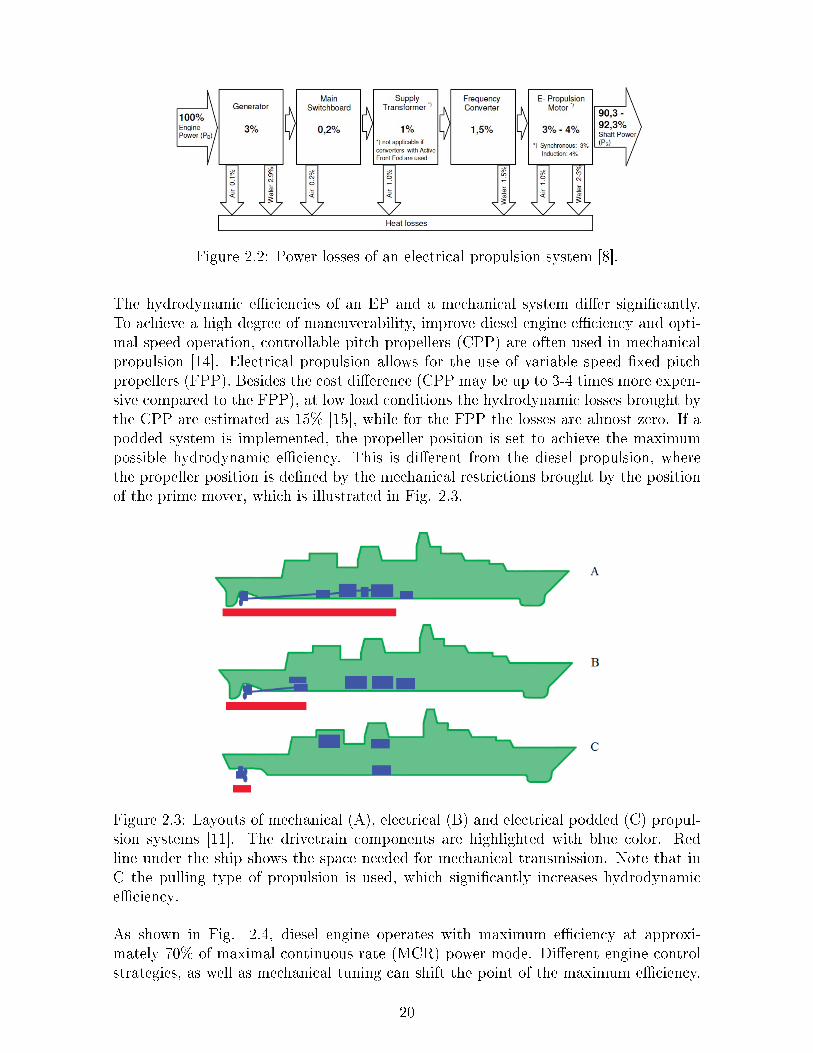
Figure 2.2: Power losses of an electrical propulsion system [8].
The hydrodynamic eciencies of an EP and a mechanical system dier signicantly.To achieve a high degree of maneuverability, improve diesel engine eciency and opti-mal speed operation, controllable pitch propellers (CPP) are often used in mechanicalpropulsion [14]. Electrical propulsion allows for the use of variable speed xed pitchpropellers (FPP). Besides the cost dierence (CPP may be up to 3-4 times more expen-sive compared to the FPP), at low load conditions the hydrodynamic losses brought bythe CPP are estimated as 15% [15], while for the FPP the losses are almost zero. If apodded system is implemented, the propeller position is set to achieve the maximumpossible hydrodynamic eciency. This is dierent from the diesel propulsion, wherethe propeller position is dened by the mechanical restrictions brought by the positionof the prime mover, which is illustrated in Fig. 2.3.
Figure 2.3: Layouts of mechanical (A), electrical (B) and electrical podded (C) propul-sion systems [11]. The drivetrain components are highlighted with blue color. Redline under the ship shows the space needed for mechanical transmission. Note that inC the pulling type of propulsion is used, which signicantly increases hydrodynamiceciency.
As shown in Fig. 2.4, diesel engine operates with maximum eciency at approxi-mately 70% of maximal continuous rate (MCR) power mode. Dierent engine controlstrategies, as well as mechanical tuning can shift the point of the maximum eciency.
20

However, Fig. 2.4 shows a common feature of diesel technology, namely that engineshave maximum eciency only in a relatively narrow range of the output power. E-ciency of electrical motors deviates much less in the range from zero to rated power.Taking into account that most of the ships spend only a small fraction of its lifetime atfull power, fuel consumption of a diesel-electric set is less compared to a directly drivendiesel propulsion unit. Figure 2.5a illustrates engine operational time in dierent modewhile Fig. 2.5b shows total fuel consumption. As can be seen from both gures mostof the engine service time and fuel is spent in non-optimal mode.
The main reason that does not allow directly driven diesel propulsion units to operateconstantly in high-eciency mode is the variation of the ship's power demand. Thesharp prole of the propulsion load, experienced by a vessel, is typical for icebreakers,supply vessels and cruise ferries. This makes EP systems especially benecial for thiskind of ships. According to [15], for a eld vessel support, the fuel savings of the diesel-electric drive are estimated as 700 tonnes per year, which is equal to $ 927,000 basedon the average marine diesel price on 20th August 2012. According to [9], a navy ship,equipped with EP, can save up to 25% of fuel. As dated by dierent shipowners, invessels with a diversied operational prole fuel savings up to 30-40% are achieved, [15].
Figure 2.4: Diesel engine eciency in the dierent power modes. SFOC stands forspecic fuel oil consumption while MCR stands for maximum continuous rate. Thedata is given for the 25 MW standard engine 6S80ME-C8.2 produced by MAN [16].
2.3 Vessel payload
By eliminating the mechanical restrictions of the direct-driven diesel engines, the variouscomponents of the electrical propulsion system can be placed at locations that oer themost ecient ship packaging (Fig. 2.3). The propulsion set room conguration can bechosen accordingly to the actual volume occupied by the components; the size penaltiesbrought by long shaft and restriction for engine placement are avoided. As an example,in EP systems the prime movers can be located higher in the ship, and thus, theventilation ducts become shorter and occupy less space. Vibration and noise producedby electrical motors are much less compared to diesel engines. Moreover, motors do not
21

produce exhaust gases. Therefore, in cruise ships the cabins can be located closer tothe propulsion room.
(a) (b)
Figure 2.5: Dierent modes of engine operation: a) Service time b) Fuel consumption.Derived from [16] for the ship equipped with 25 MW standard engine 6S80ME-C8.2produced by MAN. MCR stands for maximum continuous rate.
In the marine industry, mainly two-stroke diesel engines are installed. The power-to-mass ratio of two-stroke diesels is much lower compared to four stroke topology, whichcan be used to provide mechanical power for generators in EP (Fig. 2.6a). Calculatingthe mass of the propulsion set, one should keep in mind that a low-speed diesel isnormally equipped with a long shaft, while in EP systems a medium speed engine iscoupled with generator. Thus, it would be reasonable to compare power-to-mass ratioof two drive sets: diesel engine, equipped with shaft, and a genset. Figure 2.6b showsthat the power density of the genset is signicantly higher compared to the engineand "long" shaft used in the directly driven diesel conguration. The reduced fuelconsumption results in reduced space needed for fuel storage (for the same range). In[9] it is estimated that when electrical drives are used, 30% volume reduction is possiblecompared to mechanical propulsion systems.
2.4 Electrical propulsion for naval applications
According to the announced programs and ocial reports, U.S. Navy and Royal Navyare highly interested and actively developing the more-electric ship technology that willsuit military requirements to survivability and stealth [19, 20]. Historically, electricpropulsion on navy vessels has been used mainly on submarines equipped with DCmotors supplied with power stored in the on-board batteries. At present, the Virginiaclass submarines (SSN-774) are being equipped with electric propulsion. In 2000, U.S.Navy chose EP technology for the land-attack destroyer DD-21 after tests completedon a full-scale land-based demonstration site in Philadelphia, PA. In 2004, the rstNavy's hybrid warship LHD-8 was laid down. The ship uses diesel-electric and gas-electric propulsion. The other vessel projects, which have been constructed or planned
22

(a) (b)
Figure 2.6: Average power to mass ratio comparison: a)Low versus medium speed dieselengines b)Low-speed diesel engines and shafts versus gensets. Derived from [17, 18].
by the Navy, include (but not restricted by) DDG 1000, T-AKE, LHD 8 and LHA 6.Currently, the concept of the electric warship is being developed for U.S. Navy withthe assistance of ve corporations [10]:
Alstom, mainly working with synchronous and advanced induction motor.
General Dynamics, focusing on PMSM.
Newport News Shipbuilding, working on PMSM.
American Superconductors, developing high temperature superconducting (HTSC)motor.
General Atomics, focusing on homo-polar HTSC motor.
In 2007, Royal Navy launched "Daring", the rst of Type 45 Class destroyers equippedwith full-electric propulsion system. The British Ministry of Defense is currently fund-ing the development of its own integrated power system (IPS) program. France, Ger-many and Italy are primarily focused on the development of electric propulsion systemsfor its submarines (nuclear and non-nuclear powered). The advantages brought by theEP systems for navy applications are as follows:
Survivability.
Flexibility of the propulsion control.
Opportunity to optimize power system design for a given military mission.
Increased stealth capabilities of vessels.
23
2.5 Electrical propulsion architecture
With the appearance of electrical drives being implemented for propulsion, the shipprimary movers remain diesel engines, gas and steam turbines. However, the crucialdierence between electrical and mechanical propulsion is that EP allows to redistributepower ow produced by the prime movers and to transmit it at high eciency. Thiseliminates the need for long shafts and complex mechanical transmission. As such, dam-aged shaft will most probably stop the vessel while damaged cables from the generatorto the motors could be replaced by redundant ones at reasonable costs.
An overwhelming majority of vessels require on-board electrical systems for coveringservice needs. In segregated power systems, propulsion power and ship service powerare provided by separate prime movers. With electrical propulsion, an integrated powersystem can be implemented. In IPS systems, propulsion and auxiliary power are pro-vided by the same prime movers. In past, the propulsion and electrical system of thecruise ship would require a few large diesels to rotate the propeller, and a few of mediumsize to supply electrical hotel load. IPS allows reducing the amount of prime movers,which increases its utilization ratio and powering density. Moreover, the total num-ber of engine running hours and maintenance costs are greatly reduced. Besides, IPSimproves controlability and reliability of the ship power system.
The concept, which is being actively developed nowadays, is an all-electrical ship. Be-yond the advantages oered by IPS, in an all-electrical ship, the hydraulic and com-pressed air systems used for various kinds of loads are replaced with electrical drives.Moreover, if the developed concept will be standardized, the same common componentscould be placed on various vessels, which is clearly benecial for the vessel design anddevelopment processes.
Similar to a land-based grid, a marine electric installation includes units that generate,convert, distribute and consume electrical power. In addition, strict requirements onsafety and redundancy, over-current protection, voltage control and power management,increase the complexity of the design of electrically propelled ships.
A typical ship's power system architecture with electrical propulsion is illustrated inFig. 2.7. However, one should keep in mind that the presented architecture is open formodications in the accordance to the specic vessel electrical propulsion requirements.
2.6 Ship power system design
Diesel-electric plant sizing consists of several stages, which are shortly described in thissection. Besides the content, the given workow provides a clear insight into the scopeof works and illustrates future research in addition to this concept study.
2.6.1 Vessel power-speed relationship
At the initial stage, the propulsion and propeller types are dened according to thevessel types and sizes [14]. Ship total towing resistance, equal to the sum of frictional,
24

Figure 2.7: Typical ship power system architecture [9].
residual and air components, denes power, which should be provided by propeller tomove ship with the required average and peak speed. As shown in Fig. 2.8, powerrequired by the propeller is proportional to the speed cube at low speeds and to thefourth of the power at high speeds. Ship's maximum achievable speed, limited by so-called wave wall eect, is determined by a number of design parameters, such as hullshape and hydrodynamics. After the wave wall, further increase in ship's power abilitydoes not increase speed. Therefore, to move at 50% of maximal speed only 12.5% ofthe rated power is required. As shown, diesel engines are highly inecient at low speed.As a result, if one aims to operate diesels in a high-ecient mode, the fuel consumptionwill increase greatly with only small speed gain.
Propeller design is a complicated multi-parametric task. In large ships, 4, 5 or 6 bladespropellers are used. Propeller and engine load diagrams are used in a standard approachfor power calculations. Numerous considerations, e.g. heavy weather conditions, requireto adjusting engine power margins to cope with all possible worst-case scenarios.
2.6.2 Auxiliary electrical load
The electrical load of a ship depends on the operation mode: at sea, maneuvering, atport, etc. In modern cruise vessels, with a propulsion power of 40 MW, the hotel loadcan be up to 40%. For oshore construction vessels, the consumer load can be up to25% of the total power [8]. After these preliminary electrical loads are calculated, primemovers can be sized.
25

Figure 2.8: General dependence between ship speed and propulsion power [9].
2.6.3 Prime movers and generator set
As mentioned, medium to high-speed diesel engines (mostly) and gas turbines (less)are used as prime movers on most of the vessels. Diesel-electric drives are a maturetechnology and conventionally designed with respect to gensets and ship operationalprole. Typical large power diesel-electric drives, e.g. produced by Wartsilla and MAN,have a speed of rotation of 500-1,000 rpm and generate voltage up to 15 kV [17, 18].The generator design follows the following requirements: voltage level, availability ofreactive power and total harmonic distortion.
2.6.4 Ship power distribution
The redundancy and safety requirements determine switchboard, on-board grid voltageand frequency. The over-current protection regulation forces designers to use highervoltage levels. To increase grid fault tolerance, the switchboard is divided into 2, 3 or 4sections. If a high voltage electrical system is installed on a ship, special attention shouldbe paid to the selection of circuit breakers to avoid sparks and arcs. To provide therequired safety, the protection scheme of the ship electrical system has to be developed.Correct setting and control of the protecting devices is essential to provide a rst defenseagainst under- and over voltage, current and frequency, earth fault, thermal overload,and other fault conditions. In order to provide required isolation of dierent parts ofthe electrical power system, transformers are placed in accordance with the on-boardgrid topology.
26

2.6.5 Variable speed drives and motors
At present, about 85% of the on-board drives are used for the auxiliary systems - cranes,pumps, fans, etc. Megawatt rated motor requires powerful converters able to maintainhigh voltage levels and preferably high-frequency switching. To eliminate noise andvibration caused by converter harmonics, a large LC lter before the motor is requiredon most of ships. Due to advances in IGBT technology, PWM-VSI drives becomesuitable for 20 MW machines. PWM drives are advantageous due to their high powerdensity and eciency. Cycloconverters and load commutated inverters are widely usedin large cruise ships. Compared to other type of converters, cycloconverters have thefewest number of components. Cycloconverters are used for applications where hightorque is needed, e.g. icebreakers and dynamic positioning ships. Due to their largesize, cycloconverters are not suitable for small ships. Moreover, cycloconverters oer alimited output frequency range and suer from their low power factor. The selectionof the suitable converter type depends on ship requirements, electrical motor type andoutput power/torque.
2.6.6 Power and propulsion management system
Modern power systems are highly integrated with control networks and power manage-ment systems (PMS). These are used to monitor and coordinate power generation, loadand distribution. The design challenge is the selection of information management sys-tems and user-interface, selection of centralized or distributed system level controllers,development of the philosophy and PMS conguration.
2.7 Types of electrical propulsion
Mechanical components of diesel-electric propulsion topology include shaft, propellerand rudder. A rudder is used to move the ship in transverse directions and if additionalmaneuverability is required, a bow thruster is installed. To avoid rudders, increase drivecompactness and improve maneuverability, azimuth thrusters are sometimes installed(Fig. 2.9a). With azimuth thruster propulsion conguration, the motor is locatedinside the hull, and propulsion power is transmitted to the propeller via shafts andgearboxes. Depending on the motor location (horizontal or vertical) a Z- or L-typegear transmission are used. Azimuth thrusters are able to rotate through up to 360 inazimuthal direction.
The rst electrically podded system (POD - Propulsion with Outboard Drives), namedAzipod was introduced by ABB in 1990. Pod is a thruster unit with encapsulatedelectrical motor, which directly drives the propeller (Fig. 2.9b). Compared to azimuththrusters, pod avoids the use of a complex transmission without compromising theability to rotate 360 degrees around its vertical axis. Complete podded propulsionsystems can be delivered and tted in days, thus avoiding the lengthy installationof a conventional propulsion system. The hydrodynamic eciency is greatly improvedespecially in pulling type pods due to optimal and uniform wake eld. Overall eciency
27
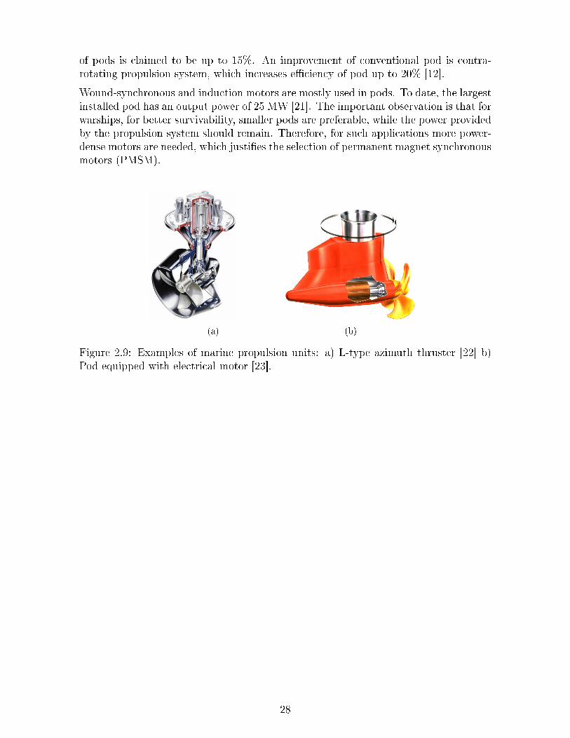
of pods is claimed to be up to 15%. An improvement of conventional pod is contra-rotating propulsion system, which increases eciency of pod up to 20% [12].
Wound-synchronous and induction motors are mostly used in pods. To date, the largestinstalled pod has an output power of 25 MW [21]. The important observation is that forwarships, for better survivability, smaller pods are preferable, while the power providedby the propulsion system should remain. Therefore, for such applications more power-dense motors are needed, which justies the selection of permanent magnet synchronousmotors (PMSM).
(a) (b)
Figure 2.9: Examples of marine propulsion units: a) L-type azimuth thruster [22] b)Pod equipped with electrical motor [23].
28

Chapter 3
Electrical Motors used for Marine
Propulsion
3.1 Propulsion electrical drive conguration
In many applications, the demand for compact and ecient electrical drive systems hascreated an opportunity for high-speed machine use. In these applications, permanentmagnet (PM) machines are recognized as a favorite, due to their high power density,relatively simple construction and high eciency. Several extremely high-speed PMmachines have been reported, both on the market and in academia, with speeds up to1,000,000 rpm. However, for ship propulsion this has not been thoroughly researched yetdue to the necessity of gearing both the speed and the torque. For example, in industrymachinery operates at greatly dierent speeds. A large cement mill or steel converterruns at fractions of a revolution per minute, while centrifugal compressors operate at5,000 to 20,000 rpm. In between these extremes, the large majority of machines arerunning at 10 to 1,000 rpm. The absorbed powers vary as widely, from fractions of akilowatt to many megawatts for ship propulsion. In this respect, gearboxes are used tomatch the operating speed of the prime mover to the requirements of the propeller. Assuch, they will be used as speed increasing or decreasing drives. Conventional gearboxescome in all sizes and ratios, transmitting a few watts in power tools to 50 or 60 MWin ship propulsion and gas turbine driven generators.
The combination of high-speed motors and gearing is well known for power tools. Thesedrives, up to some kilowatts power at 20 to 30,000 rpm, do not pose problems foreither gearing or bearings, and are well established technology. The advent of cost-eective frequency converters has allowed the speed range of larger induction motorsof 100 to 1,000 kW to be increased to 4,000-6,000 rpm. The prospect of a permanentmagnet motor of 20 MW operating at higher speed oers the possibility of low mass,very compact geared or direct-drive, which have been used at these higher speeds fordecades, i.e. in combination with both steam and gas turbines.
29
3.2 High-speed electrical machines
The boost in speeds of PM machines is linked with overcoming or avoiding a numberof machine limitations. Various physical parameters (stress, temperature, resonantfrequencies) can limit the speed of an electrical machine. Aside from speed, thesevariables are also aected by power, size and machine electrical and magnetic loading.The tangential speed at the outer rotor radius is often taken as a criterion when deninghigh-speed because it also takes into account the size of a machine. High-speed machinesare classied according to operating power and rotational speed. A numerical limit isproposed in this report that correlates the power limit with the rotational speed of anelectrical machine.
3.3 Power electronics
The rapid development in marine propulsion has a signicant thrust towards the useof electrical propulsion and the integration of auxiliary and propulsion power systems,where the need for very exible, robust and compact power systems is ever increasing.This need is going to be satised through recent advances, verging on revolution, inpower electronic device construction, and their application for power conversion andcontrol. Further, in electrical propulsion, the power is provided by generators to thepropulsion motors. Therefore, the ship constitutes an island grid, hence active powerto frequency and reactive power to voltage balances have to be matched, uctuationsare also allowed other than in onshore grids, where enough control reserve has to beprovided to keep the frequency and voltage nearly constant. So, system stability is arelevant concern in island installations. Modern AC to AC power conversion systemsoer the advantage of compact, ecient and bi-directional power modulation for shipdrives in the range of 2.6 to 4.5 MW.
The recent developments in switching device implementation have been fundamentalto the developments underway in marine electrical power systems. The application ofmultilevel inverters has been very attractive for medium to high voltage range (2 to 13kV) applications such as: motor drive systems, power distribution, power quality andpower conditioning applications. The ability to apply these new techniques to hybridelectric drives for ships results in hardware selection that allows very low harmonicdistortion of the output waveforms and consequent smooth operation over the entirespeed range.
3.4 Electrical motors for marine propulsion
Generally, the selection of the motor for electrical propulsion is based on the preferenceof the shipbuilder, since dierent motor types have dierent advantages and disad-vantages. Moreover, one can notice that dierent manufacturers promote their ownsolutions as the best suitable for marine application. Hence, the motor selection de-pends on the motor producer's reputation. For example, ABB has installed more than
30

120 pods with induction motors, while Siemens is concentrated on the high-temperaturesuperconducting and permanent magnet synchronous motors.
The specic motor requirements to marine applications can be classied as follows:
High reliability.
High compactness.
High shock-resistance.
Low power consumption.
Low emission.
Based on reports, industrial experience and performance characteristics of the availablemotors, the following types should be considered as candidates for the ship propulsion:
Induction motors.
Wound-eld synchronous motors.
High-temperature superconducting (HTSC) synchronous motors.
Permanent magnet synchronous motor.
3.4.1 Induction motors
Induction motors (IM) oer robust design and comparatively low costs. It is a maturetechnology and most widely used in the heavy industries. IM have been used fordecades in marine applications and have been installed on a large amount of vessels indierent congurations. Advances in IGBT technologies have assisted in the productionof ecient converters. A possibility to connect multi-phase (12 to 15) high-powermachines, controlled by PWM-VSI drive, directly to the converter without transformersis a great advantage in terms of mass and cost reduction. However, even the mostecient IM installed nowadays are comparatively heavy and occupy a lot of space. Forexample, a 20 MW 180 rpm advanced induction motor (AIM), produced by Converteam,has a mass of some 100 tonnes [24].
3.4.2 Wound-eld synchronous motors
According to [25], wound rotor synchronous AC motors are the most used structure inship propulsion for the last decade. Wound eld motors are more ecient than induc-tion motors. However, the excitation system of the motors requires additional space.Therefore, compared to permanent magnet synchronous motors, the power density ofwound rotor motors is lower. The wound-eld motors are a reasonable solution forcommercial vessels, however, for navy applications and pods more compact solution arepreferred.
31

3.4.3 High-temperature superconducting motors
Since the 1970s high-temperature superconducting materials have been investigated. Inthis respect, high temperature refers to 30-40 K, which is much higher than 5 K - anormal temperature when superconductance is reached [26]. American SuperconductorCorporation has built and tested a 36,5 MW, 120 rpm motor [10]. The mass of such amotor is some 75 tonnes. GE initiated the development of a 100 MW generator thatemploys an HTSC eld winding. During the last decade the technology of HTSC hasbecome commercially available, however, this technology is still under development andtesting.
The key feature of the superconducting motor is the additional cryogenic equipment tocool the conductors below the temperature when the eect of superconductance takesplace. The small resistance of superconductors allows the current density to be upto 100 times compared to conventional machine. Thus, potentially HTSC oers thehighest power density and energy eciency. However, one should keep in mind thatthe cooling equipment poses an additional technical risk and notably increase the costsof the system.
3.4.4 Permanent magnet synchronous motor
The permanent magnet synchronous motor (PMSM) oers a high power density atreasonable costs. Fig. 3.1 illustrates the eciency of high-power induction motorcompared to a PMSM. The PM motor eciency can reach values of 98% while theeciency of induction motors is limited to 94-96% at full load. However, at part loadthe PMSM motor clearly shows its advantage. PMSM are less aected by rotor currentloss, less noisy and much more compact compared to IM. Although that the maindisadvantages of PMSM are magnet costs, magnet sensitivity to high temperature andpartial demagnetization.
To summarize, Table 3.1 shows the key features of dierent motor types suitable formarine propulsion.
32

Figure 3.1: Comparison of eciencies of PM and induction megawatt machines. Oneshould note that the eciency of synchronous machines is similar to the eciency ofinduction machines. The gure is based on the data provided by Advanced Electro-magnetics B.V. [27].
Motor type Advantages Disadvantages
IM Robust, relatively cheap andsimple.
Low eciency, low powerdensity.
Wound rotor Compared to IM more shockresistant because of larger airgap, have higher eciency and
power factor.
Need separate windingexcitation; brushes and sliprings add complexity and
maintenance costs.PMSM High power density, low noise,
maximum torque at zero speed.Thermally sensitive,
operation at high speedsneeds rotor enclosure.
HTSC Oer potentially highest powerdensity and energy eciency.
Need complex cryogenicequipment. Non-mature
technology. At present dateonly a few large-power
machines exist.
Table 3.1: Brief comparison of the motors to be used for ship propulsion.
33

3.5 Conclusion
Concept of megawatt high-speed machine
Present low-speed permanent magnet motors have reached powers of 65 MW [28]. Atthe same time, high-speed permanent magnet synchronous motors (PMSM) have beenused in a great variety of applications and achieve speeds of up to 1,000,000 rpm [29].Although the design of megawatt high-speed machine is still a challenge, such machineshave become commercially available [4], and are currently used mainly in oil & gas andpetrochemical industries.
Electrical propulsion in the marine sector is an emerging technology oering a widearea for the future research and development. Progress observed in PMSM technologycoupling with long-term costs benets gives a promising topic for research of permanentmagnet motors installed in ship propulsion systems. Use of high-speed PMSM oersincreased eciency and compactness compared to most currently implemented motors.A gearbox system is a necessary component of the drivetrain when high-speed motoris employed, however the increased mechanical complexity of geared motor is justiedby the potential mass reduction, which, according to the preliminary expectations, canbe up to 50% greater compared to the low-speed induction motor without the gearbox.A thorough analysis will be carried out in the following sections in order to assess thefeasibility and performance of the chosen concept.
34

Chapter 4
Preliminary Machine Sizing
Introduction
Multi-megawatt high-speed PM machines are characterized by a robust rotor construc-tion since they are typically speed-limited by the strength of the materials chosen. Thisnarrows the rotor topology of choice to a surface-mounted or embedded magnet con-struction [30, 31]. The non-magnetic sleeve, illustrated in Fig. 4.1, is used to achievenecessary mechanical retention of the surface magnets, which increases the eectivelength of the air gap, and, therefore, decreases ux density for a given magnet height.Embedded magnets do not need any external enclosure, however, experience higherinterpole ux leakage, which also decreases maximum achievable air gap ux density.Because of the advantages related to the manufacturing process and simpler analyticaldescription, the surface mounted magnets are selected for the current design.
Figure 4.1: Layout of PM motor with surface-mounted magnets and carbon sleeve. Thegure is a front view of a 3D model built by the means of CAD software.
The basic rotor arrangement types are the following: exterior, interior and double ro-tor. Exterior rotor could be more compact because of the higher radius, and, as aconsequence, higher torque, compared to the interior-rotor machine of the same size.However, the exterior rotor makes cooling system more complicated. To avoid overheat-ing, the electric loading is decreased, which diminishes the achievable shear stress. Dual
35

rotor machine is a novel technology, which has recently appeared on the market. Al-beit dual rotor could eliminate the need for a gearbox, the machine structure becomesmore complicated and less robust, which is critical for the durable operation at thehigh speeds for megawatt machine. Therefore, interior-rotor surface-magnet structureis selected as the most appropriate for the high-power high-speed motor.
4.1 20 MW high-speed PMSM: design challenges overview
A high speed of rotation as well as a high power rate are the reasons to pay additionalattention to the following issues [4, 32]:
Rotordynamical issues.
Magnet enclosure design (for surface mounted magnets).
Cooling system and motor thermal vulnerability.
Power converter capabilities (maximum switching frequency for high voltage).
Losses.
Vibration assessment.
Bearing durability.
Rotordynamical issues mainly determine the maximum dimensions of rotor. Rotationalcritical speeds should be considered to avoid rotor bending and excessive vibration. Sur-face mounted magnets do not add stiness to the rotor, however, act as deadweightsand, therefore, should be covered by an enclosure. The enclosure is usually made ofnon-magnetic carbon, which enlarges the eective air gap of the machine and decreasesachievable air gap ux density. A high current density in the slot increases require-ments to the cooling system especially when the machine surface area is comparativelylow. To decrease losses occurring at high speeds, an appropriate iron type and strandconguration should be selected carefully [4]. Finally, the power converter should beable to support the necessary switching frequency at high voltage levels.
4.2 Rotor diameter, mass and rotational speed
The two basic equations linking power of the machine with its sizes are the following:
T = 2σVr (4.1)
P = Tw (4.2)
36

where T is torque, σ is shear stress, w is rotational frequency in rad/s , P is power andVr is a rotor volume.
Coupling (4.1) and (4.2) results in the following equation:
P = π2D2r lsσn (4.3)
where Dr is rotor diameter, ls is rotor length and n is rotational speed.
One should keep in mind that shear stress is dependent on the machine diameter dueto the thermal restrictions. Assuming a constant number of slots and constant currentdensity, slot current I is proportional to D2
r . The heat generated in the slot regionis dissipated through the back iron (including tooth body) and the end plates. Thesurface of the end plates is proportional to D2
r , and the surface of the tooth wall isproportional to Dr. Hence, the dissipation area can be expressed as:
Ad ∝ Dmr (4.4)
where 1 < m < 2 [33].
The slot heat generation is proportional to the slot current, thus, to D2r . As a result of
(4.4), the increase in the slot current is faster than the increase in the area of dissipation.The condition for thermal balance makes the shear stress inversely proportional to therotor diameter:
σ = 0.5 · B · A ∝ Dm−1r
where B and A are peak values of the fundamental waves of magnetic ux density andelectric loading correspondingly. According to [33] the theoretical value of m is 1.25.To illustrate the importance of the derived proportion, let us assume a machine with arotor of 1 m in diameter and calculated shear stress of 50 kN/m2. The machine of thesame power and rotor volume with diameter of 0.5 m will have a shear stress of:
50000 · 0.50.25 ≈ 42 kN/m2 (4.5)
The machine output power directly depends on the rotor volume, therefore, for a rstorder estimation, to increase machine power one need to increase rotor volume. Ap-parently, the rotor volume can be increased by varying the length or diameter of therotor. An important conclusion following from (4.5) is that for the same power increaseone would need less rotor volume increase if one enlarges the rotor diameter instead oflength. Hence, (4.3) might be rewritten as follows:
P ∝ D2.25r lsn (4.6)
It follows from (4.3) that keeping the produced power constant, the increase in speedresults in decrease of the machine volume and therefore mass. This explains why it ispreferable to increase the speed of the rotation as much as possible. However, (4.3) doesnot show a speed limit of the machine with a given rated power. This limit is rarely
37

derived analytically. However, authors of [29, 34] proposed that machine maximumspeed is inversely proportional to the rated power according to (4.7).
Pmax ∝1
n3max
(4.7)
This empirical limit has been proven by GE research. Markers in Fig. 4.2 are placedaccording to the rated characteristics of the existing machines. Interpolating the data,one could nd a line that follows the empirically established law, linking machine powerand achievable speed. According to this line, it is expected that the machine of 20 MWcan rotate at 10,000 rpm. Dated highest speed megawatt machine, has a power of 8MW and rotates at 15,000 rpm.
Figure 4.2: Power and speed ratings of "commercially" produced motors. Derived from[35]. The blue break line shows assumed machine power for the whole range of theillustrated speeds. WFSM stands for wound-eld synchronous motor, IM for inductionmotor, PM for permanent magnet motor.
If to investigate only mechanical constraints of multimegawatt high-speed machines, asimple equation can be employed to estimate maximal rated power for a given speed.As it follows from [34], the maximal rotor length is calculated as follows:
lmax =
√√√√ π2
kΩ
√EI
ρS(4.8)
Where S is the area of the cylinder cross-section, E is Young's modulus, I is the secondmoment of inertia for a cylinder, k is , Ω is rotational frequency and ρ is materialdensity. For a solid rotor of an electrical machine the second moment of inertia isequal to I = πD4
r/64. The maximum rotor diameter is determined by the maximalsurface speed and, therefore, lmax can be found. When rotor dimensions are dened,the maximal generated torque of the machine will be dependent only on the shear stress.If shear stress is taken as 50 kN/m2, the maximum rated power of the machine is 29MW.
38

(a) (b)
Figure 4.3: Results of design calculations of 20 MWmotor with 1.5 m rotor diameter and50 kN/m2 shear stress a) Rotor mass versus rotational speed b) Rotor mass versus rotordiameter. The maximum value of the rotor diameter for a specic speed is restrictedby a maximum surface speed.
Equation (4.6) allows to estimate the potential mass reduction of a high-speed machine.Assuming that 20 MW motor with a diameter of 1.5 m has a shear stress equal to 50kN/m2, with increase of the rotational speed the mass of the machine will decrease asit is illustrated in Fig. 4.3a. However, Fig. 4.3a is created with the assumption thatthe magnetic loading is constant with speed change. In practice, because of magnetenclosure, the magnetic loading decreases. As a result, the shear stresses also decreaseand, therefore, Fig. 4.3a should be treated only as an initial result. Still, it gives a clearunderstanding of interdependence of rotor diameter, mass and rotational speed.
4.3 Electrical machine design
Electrical machine design is a complex process that is based on the analytical assessmentas well as on empirical data, nite-element modeling and experience of its designer. Theiterative nature of the design calculations is stipulated by the strong interdependenceof multiple design variables. Typically an existing machine is used as a template for theinitial sizing. This allows designers to gradually adjust machine parameters to satisfythe posed requirements. Because of the lack of information about existing megawatthigh-speed machines, there is no template data" for the current design. As a con-sequence, the main motor dimensions are calculated based on well-known and provenassumptions. FEM is used to calculate strongly non-linear characteristics and verifyobtained topology. The empirical data and recommendations of industrial partners playa crucial role in the assessment of the obtained results.
To clarify the design process, the following steps are distinguished:
1. The empirical data research.
39

2. Selection of the design variables.
3. Analysis of the constraints brought by the variables.
4. Establishment of the initial value for the parameters, based on the rst threeitems.
5. Analytical calculation of the basic geometry and machine performance.
6. FEM results.
7. Correction of the initial values, recalculation.
An optimal design of the machine is an extremely complicated task when the numberof design variables is not limited. To restrict the area of possible design solutions, a setof variables is assigned with a constant value. Such variables are dened using practicalconsiderations, or their change does not inuence the design strongly. Further, a list offree variables is created. The free variables are the variables that are independent ofeach other and determine the main machine dimensions and performance. Table (4.1)illustrates the design variables, its desired value and imposed constraints, which arediscussed in details in the sections below.
4.4 Design variables
4.4.1 Magnetic loading
Machine dimensions. To estimate magnetic ux density, rotor dimensions shouldbe known a priori. Fig. 4.3b shows that for a given speed the mass of the rotor is lowerif the diameter is larger. At the same time, as can be seen in the Fig. 4.3b, there isa limit to the rotor enlargement for a specic speed, because of the restriction for therotor maximum surface speed, which is taken as 250 m/s. The rotor length is calculatedto avoid the rst critical speed. Figure 4.4 illustrates the maximum rotor length versusdiameter for various rated speeds. For a specic rated power dierent combinationsof rotor length/diameter are possible. As a clear analytical solution for the optimummachine length/diameter ratio is hard to derive, empirical data may be referred to.
The empirical data is contradictory. According to [36], the cost of the machine isproportionally dependent on the rotor diameter. Also the end-winding to the machinelength relation is lower when the rotor length is higher. However, a short rotor isbenecial from the point of view of bearing durability. Moreover, as was mentioned,slot heat dissipation is proportional to the end-winding surface. Therefore, the largestpossible rotor diameter will be chosen for the design as presented in this report.
The number of poles is mainly restricted by the maximum supported frequency ofthe converter. Assuming that the commercially available converter Perfect Harmony,manufactured by Siemens [37], can be used for the machine drive, the number of polesshould be either 2 or 4. At the same time, the increase in the number of poles leads to adecreasing ux per pole. If the ux per pole decreases, the stator teeth can be thinner.
40
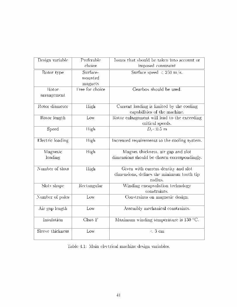
Design variable Preferablechoice
Issues that should be taken into account orimposed constraint
Rotor type Surface-mountedmagnets
Surface speed < 250 m/s.
Rotorarrangement
Free for choice Gearbox should be used.
Rotor diameter High Current loading is limited by the coolingcapabilities of the machine.
Rotor length Low Rotor enlargement will lead to the exceedingcritical speeds.
Speed High Dr<0.5 m
Electric loading High Increased requirements to the cooling system.
Magneticloading
High Magnet thickness, air gap and slotdimensions should be chosen correspondingly.
Number of slots High Given with current density and slotdimensions, denes the minimum tooth tip
radius.Slots shape Rectangular Winding encapsulation technology
constraints.Number of poles Low Constraints on magnetic design.
Air gap length Low Assembly mechanical constraints.
Insulation Class F Maximum winding temperature is 130 oC.
Sleeve thickness Low < 3 cm
Table 4.1: Main electrical machine design variables.
41

Figure 4.4: Rotor maximum length versus diameter given for the dierent speeds.Calculated for 20 MW machine with 80 kN/m2 shear stress design.
As an example, doubling the number of poles decreases the yoke length by half. A smallnumber of poles leads to a large end-winding, which is undesirable, because it resultsin ux penetrating the shaft.
Besides protective sleeve, magnetic ux generated by magnets passes the air gap whichhas a high reluctance. Although the air gap is of great signicance for machine design,usually empirical equations are used to dene its length. Typically, air gap length doesnot vary tremendously for a machine of dierent power. According to [38], air gaplength, expressed in meters, can be dened as:
g = 0.0002 + 0.003
√Drls
2(4.9)
However, in practice the limit for the minimal air gap length is dened by the mechanicalrestrictions and therefore is selected to be 4 to 5 mm. The considerations referred tothe demagnetization resistance can be neglected because of comparatively thick magnetenclosure for the surface mounted permanent magnet rotor.
Sleeve calculation. To estimate the mechanical forces experienced by the rotor en-closure, well-established analytical expressions can be used. If the thickness of a rotatingcylinder is approximately 5 to 10 lower than its internal radius, the hoop stress can becalculated as long as the uniform radial pressure P , occurring at its bore, is known:
σh =PRi
t(4.10)
where t is the thickness of the cylinder, Ri is the inner radius and σh is the hoop stress.Basically, (4.10) reects the fact that for a given pressure, the cylinder should be thickenough to not exceed the maximum ultimate tensile strength of the material.
The cylinder internal pressure Pm can be calculated from the centrifugal force, producedby magnets, which act as a dead-weight. However, the inertial mass of the rotating
42

sleeve should be also taken into account. The maximum hoop stress occurs on the sleeveinternal surface. Assuming that radial stress is zero and sleeve material is orthotropicand homogenous, the total stress occurring on the inner surface of the sleeve is:
σtot = σs + σm (4.11)
where σs is the stress caused by the rotation and σm is the stress caused by magnetpressure.
For safety reasons, the maximum allowable stress σtot could be taken equal to 70%of the ultimate tension strength of the material. The highest hoop stress experiencedby the sleeve occurs when the rotor is cold and rotational speed approaches lift-ospeed. To avoid magnet detachment under these conditions, sleeve pretension is used.Considering the latter and the sleeve thermal extension, (4.11) should be modied to:
σmax = σT + 2σtot (4.12)
Equation (4.12) links two variables, namely sleeve thickness and magnet height. Anincrease in magnet height requires enlargement of sleeve thickness and, therefore, thereis an optimal relation between sleeve thickness and magnet sizes in terms of maximumux density per magnet volume and maximum achievable ux density.
Optimal magnet thickness. Magnets should have sucient volume to keep the uxdensity in the air gap at the desired value. Normally, the thickness of the magnet is5 to 10 times greater than the length of the gap [30]. Very thick magnets (> 20 mm)are complex to manufacture. If the magnet width is lower than the pole pitch, theinterpole space should be lled with material of a similar mass density as the magnets.The material should be non-magnetic to avoid ux leakage and non-conductive to avoideddy currents. In large machines magnets are segmented in transverse and longitudinaldirections.
The peak of the rst harmonic of the ux density in the air gap typically does not exceedthe value of 0.9 T [34]. However, because of the retaining sleeve and losses, causedby operation in a high-speed mode, the maximum achievable average ux density isabout 0.4 to 0.5 T. Allowable ux density of the tooth and back iron is limited by thesaturation of the material, and typically is below 1.5 T. For the exterior rotor, the shellux density should be less than 1.2 T [30].
Fig. 4.5b illustrates the required sleeve thickness for a given magnet height, while Fig.4.5a shows the achievable ux density generated by the magnet of the correspondingheight. According to the empirical data, a sleeve thickness exceeding 30 mm should notbe considered feasible [39]. Consequently, to analyze the plot with dimensionless coef-cients, the maximal feasible magnet height requires a sleeve thickness of 30 mm. Theux, which is produced by this maximum magnet height, is correspondingly assumedto be the maximal achievable ux. If Fig. 4.5a was redrawn in terms of comparativedimensionless coecients, one would see that 90% of the maximum ux density is gen-erated by a magnet with a height that is 35% of the maximum one. In terms of costsit is preferable to have a smaller magnet and thinner sleeve, although the ux density
43

(a) (b)
Figure 4.5: Calculated magnet height versus a) Sleeve thickness b) Flux density. Thedata is given for 20 MW 10,000 rpm motor design.
will only approximate possible maximum. Thus, the magnet height, which generates90% of the maximum studied ux is taken as an optimum.
To illustrate the dependence of the optimal magnet height on the rotational speed, Fig.4.7 should be referred to. The ux density drops with the increase in speed because ofcorresponding enclosure enlargement (Fig. 4.6b).
4.4.2 Current loading
Thermal calculations. Assuming that the magnetic loading is at the maximal achiev-able level, current loading denes the maximal shear stress produced by motor. Thisshear stress level then denes the torque capability of the machine within given limitsof rotor volume. The average shear stress of non salient-pole synchronous machineswith indirect cooling is in the range of 33.6 to 65.5 kN/m2 and can have the maximumvalue up to 148.5 kN/m2 in direct-water cooled machines [34].
The maximum current loading of the machine is restricted mainly by the temperatureconsiderations. With an insulation of class F, the maximum allowable winding temper-ature is 130 oC. For specic cooling capabilities, the maximum current loading dependson the slot dimensions. Keeping the ratio of slot width to the slot height as 0.5, wind-ing temperature can be kept below the maximum value when increasing the slot depth.However, according to [40], after 200 mm, further increasing the slot height results ina relative increase in current loading.
Because of the high currents and relatively small sizes, machine thermal capabilitiesshould be carefully studied to avoid damage caused by overheating. A detailed thermalmodel will be presented in the following sections, however, slot temperature distributionshould be known at the stage of the initial sizing to dene the slot geometry.
A simplied thermal lumped-parameter circuit can be employed to dene the slot size[41, 42]. First crucial assumption is that the hottest spot is located in the top of the
44

(a) (b)
Figure 4.6: Calculation results of 20 MW PM design: a) Normalized magnet heightversus normalized magnet density b) Optimal sleeve thickness versus rotational speed.
(a) (b)
Figure 4.7: Calculation results of 20 MW PM design: a) Optimal magnet height versusrotational speed b) Normalized ux density versus rotational speed.
45
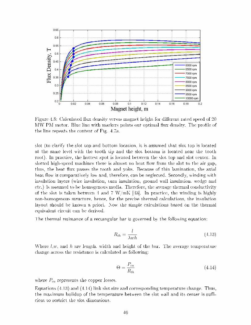
Figure 4.8: Calculated ux density versus magnet height for dierent rated speed of 20MW PM motor. Blue line with markers points out optimal ux density. The prole ofthe line repeats the content of Fig. 4.7a.
slot (to clarify the slot top and bottom location, it is assumed that slot top is locatedat the same level with the tooth tip and the slot bottom is located near the toothroot). In practice, the hottest spot is located between the slot top and slot center. Inslotted high-speed machines there is almost no heat ow from the slot to the air gap,thus, the heat ux passes the tooth and yoke. Because of thin lamination, the axialheat ow is comparatively low and, therefore, can be neglected. Secondly, winding withinsulation layers (wire insulation, turn insulation, ground wall insulation, wedge andetc.) is assumed to be homogenous media. Therefore, the average thermal conductivityof the slot is taken between 4 and 7 W/mK [43]. In practice, the winding is highlynon-homogenous structure, hence, for the precise thermal calculations, the insulationlayout should be known a priori. Now the simple calculations based on the thermalequivalent circuit can be derived.
The thermal resistance of a rectangular bar is governed by the following equation:
Rth =l
λwh(4.13)
Where l,w, and h are length, width and height of the bar. The average temperaturechange across the resistance is calculated as following:
Θ =Pcu
Rth
(4.14)
where Pcu represents the copper losses.
Equations (4.13) and (4.14) link slot size and corresponding temperature change. Thus,the maximum buildup of the temperature between the slot wall and its center is su-cient to restrict the slot dimensions.
46

The equivalent resistance in the thermal circuit is used to model heat transfer betweendierent machine components, such as frame, end-plates, stator and rotor core and soon. Therefore, to determine all the thermal circuit components, it is necessary to knowthe machine geometry. At the initial stage of machine design, to restrict slot dimensions,it is reasonable to assume that the slot is the only source of heat generation and heatis removed through the slot walls in radial and tangential direction. It is worth notingthat slot dimensions, calculated in a such way, will show the minimal slot surface thatis necessary to satisfy (4.14).
Number of slots. With a given electrical loading and air gap diameter the numberof slots is strictly interconnected with the slot size, which aects the current density.The latter depends on the current and therefore on the number of slots. To make anappropriate selection, an iteration procedure should be applied.
Before calculating current loading, the maximum voltage of the machine should bedened. The voltage is mainly restricted by the capabilities of the converter and thewinding insulation. Already mentioned Perfect Harmony is able to support voltagesup to 12 kV.
Given the maximum back-EMF supported by the converter, the maximum numberof turns per phase can be found. Number of slots should be integer and number ofconductors in the slot should be even (for a double-layer winding). These constraintsseverely restrict the domain of feasible solutions. The feasible slot numbers againstwinding factor are presented in Fig. 4.9.
(a) (b)
Figure 4.9: Calculated number of slots: a)Winding factor b)Percentage of unoccupiedslot space due to the geometrical restrictions. The data is given for 20 MW PM motordesign.
In large machines rectangular slots are used with a nonmetallic wedge. The wedge isused to keep the stator bars tight in the slot and to resist mechanical forces experiencedby winding. Dummy slots might be used to decrease the cogging torque. As a slot width,the appropriate height of stator and rotor yokes is selected to avoid ux saturation.
47

Figure 4.10: Calculated slot bottom diameter versus number of slots. The data is givenfor 20 MW PM motor design.
Fig. 4.10 illustrates that the slot depth is higher when the number of slots is lower. Witha given air gap diameter the number of slots denes the slot width. As a consequence,when the slot width is high, in order to prevent winding overheat, the slot height shouldbe increased to provide sucient surface for the thermal ow.
4.4.3 Reactance
When the aim of the machine control is to maximize output torque, the synchronousreactance and machine back-EMF will dene the required terminal voltage and thereactive power to be supplied from the converter. The converter rating increases as theinverse of the power factor, which means that machine with high reactance will requirelarge and costly electric drive. The power factor of the machine can be increased by themeans of control, however, the improvements in power factor in general will inevitablyreduce machine shaft power.
The synchronous reactance of the surface magnet three-phase machine is written asfollows:
Xq = Xd = wm · p · Ls (4.15)
where Xq is q-axis reactance, Xd is d-axis reactance, w is machine mechanical angularspeed, p is a number of pole pairs and Ls is synchronous inductance.
Neglecting stator end-winding and slot ux leakages, the synchronous inductance isdened as follows:
Ls = L−M
where L is a phase self-inductance and M is mutual inductance, which is equal to 12Ls
for a sine-wound machine. L is governed by the following equation:
48

L =4µ0τpls(kwQs)
2
π2pδeff(4.16)
where τp is a pole pitch, ls is rotor length, kw is winding factor, Qs is a number of slotsand δeff is the eective length of the air-gap, which reects the magnetic reluctanceof the machine main magnetic circuit. Therefore, the synchronous inductance andreluctance are lower when the machine eective air-gap is higher.
The high speed of rotation increases machine reactance. At the same time, as was men-tioned above, the retaining sleeve increases the eective machine air-gap and, therefore,decreases inductance. In the section above, the optimal sleeve thickness was selectedonly with consideration of the optimal air-gap ux density. As it follows from (4.16),the obtained inductance can be also taken into account when the sleeve thickness ischosen.
An alternative manner to decrease reactance is to decrease the number of winding turnsper phase. Yet, extremely small number of turns per phase (one turn per two slots) willlead to the mechanical complexity, so as it will be dicult to rmly x a conductor ina slot.
The use of concentrated windings instead of sinusoidally distributed can be anotheroption to decrease inductance. However, because the number of machine pole pairs islow, the selection of feasible slots/poles combinations is severely limited. To implementthe concentrated winding on the machine with 2 pole pairs and 48 slots, one wouldneed to use four converters connected in parallel.
The synchronous reactance of the machine plays an important role in the selection ofproper electric drive. It should be noted that analytical calculations of the reactancepresented above are not enough for an accurate assessment and, therefore, a nite-element modeling should be employed.
4.5 Gear
4.5.1 Assessment of gearbox mass
As was mentioned, typical rotation frequency of the propeller on the heavy vessel isabout 150 rpm [9, 14]. Motor operating at the speed of 10,000 rpm will need gearingratio of 66:1 with output torque of 1,300 kNm to make the drive system feasible. Toestimate the mass and feasibility of the gearbox with required characteristics, the carefulreview of the empirical data and manufacturer's data sheets is necessary.
Epicyclic gearboxes, as illustrated in Fig.4.11, provide high torque density and aresuitable for high-power applications. As an example, 12 MW 5,600 rpm three-stageepicyclic gearbox with a ratio of 75:1 has a torque density of 250 kNm/m3 [45], whilethe torque density of the motor with a shear stress of 50 kN/m2 is 100 kN/m2. Therefore,it can be initially assumed that mass of a combination of a high-speed motor and agearbox will be lower than mass of low-speed motor alone. On one hand this assumptionis valid as long as torque density of the gearbox is much higher than the torque density
49

Figure 4.11: Sketch of a typical epicyclic gearbox. ω and T are angular frequency andtorque correspondingly, and subscripts p, s, r, c denote planet gear, sun gear, ring gearor carrier arm [44].
Figure 4.12: Gearbox mass versus input torque. Based on the datasheet of [46].
of the machine. However, the latter should be treated carefully. Generally, shear stressat high speeds becomes lower so as the machine diameter become lower, following therestriction of the maximum surface speed. Therefore, the torque density of the motordrops. If the same is valid for a gear and for a given power, increase of the gear ratiowill result in decrease of the torque density, than there should be an optimal speed thatwill lead to the lowest possible volume of the propulsion system. To get more preciseinformation on what speed the machine should be used to minimize the total mass,a gearbox should be designed. In this respect, this report provides some rst orderestimates to determine the gearbox mass and volume.
As there is a lack of empirical data on gearboxes for the applications of more than 10MW, modern wind turbine gearboxes are taken as a reference to estimate the possiblemass of the gearbox for 20 MW drive system. The GPV500D model produced by BoschRexroth is investigated. The following preliminary assumptions are derived:
1. Gearbox mass depends on the maximum input/output torque (Fig. 4.12). With
50
a given torque, power rating of the gearbox aects only the speed of rotation ofthe pinions that should not exceed 250 m/s [45]. Therefore, if this limit is notexceeded, the machine mass will be independent on power in a short range thatdepends on the gear construction and diameters of the pinions.
2. To compensate the power increase of 20 MW gearbox compared to GPV500Dit is assumed that additional stage should be used, which will increase the massapproximately on 1:4. As it follows from Fig. 4.12, the expected mass of a gearboxfor 20 MW machine will be approximately 20 tonnes.
3. Typical gear ratio for epicyclical gear is between 1 and 12. However, the amountof teeth inuences the pinion diameter and therefore gear ratio aects the massof the pinions. If it is assumed that the gear ratio is constant in this range, for athree stage gearbox theoretical range of the constant mass is 1 : 12 × 1 : 12 × 1 :12 = 1 : 1728. Still, for a combined type of gear mass dependence on the gearratio should be treated with caution.
4.5.2 Mechanical gearbox design
To design a gearbox a lot of dierent parameters and factors should be analyzed, suchas teeth proles and its thickness, meshing interference, allowable stresses and bending,and many others. Practical issues of gearbox design process are well described in [47]and the complete theory of machine design is given in [48]. These can be used asguidelines for approximate calculations. It will be shown further that having madea number of assumptions it is possible to estimate geometry and conguration of agearbox that satises the requirements to input torque, speed and gear ratio, presentedin Table4.5. The design of GPV500D is chosen as a reference to assist in proper selectionwhen multiple options for certain parameters are available during design process.
To achieve high-torque densities and a high gear ratio, a compound two-stage epicyclicgearbox is used, sketch of which is illustrated in Fig. 4.13. At the initial stage of thedesign it is complicated to estimate optimal split of gear ratios between two stages.However, keeping in mind that epicyclical gears maximum gear ratio is 1:12, it can beassumed that the rst stage would have a ratio of 1:11 and the second stage a ratio of1:6, thus, in total, providing ratio of 1:66, as required for 20 MW propulsion system.
There are three main congurations of a typical epicyclic gearbox, depending on whatgear is xed and does not rotate. In a chosen conguration a sun gear of the secondstage is attached to the arm carrier of a rst stage and electrical motor shaft is attachedto the sun gear of a rst stage. Therefore, the only component that can be xed in suchconguration is a ring gear. The amount of planets does not aect gear kinematicsand can be chosen rather freely. Typically, there are 3 to 6 planets in an epicyclicgearbox, however, for specic applications this number can be dierent. After the gearconguration has been dened, approximate gear geometry can be calculated.
To calculate rotational speed of gears, the tabulation method, described in [47] can beused. For a chosen gearbox conguration, the following relations between sun, carrier,planets and ring gears are valid:
51

ns
nl
= 1 +Na
Ns
(4.17)
Na = Ns + 2Np (4.18)
where ns and nl are rotational speeds of sun and carrier, and Na, Np and Ns are numbersof teeth of the ring, planet and sun gears, correspondingly.
As it follows from [47], for heavy duty and high-speed applications, the minimum num-ber of gear teeth is 16. However, for the sake of stability and safety, the number ofteeth of a sun gear is taken as equal to 20.
To calculate gear geometry, tooth proportions should be known. To characterize ge-ometry of gears independently on the number of teeth, a standard basic rack toothprole is used, dimensions of which can be found in [49]. With simplied calculations,selection of a standard basic rack ensures proper gear meshing, so as teeth of all gearsbelonging to a concrete stage will have the same thickness.
For determining the gear pitch circle diameter D (hereinafter is referred to as geardiameter), a power rating equation can be employed [50]:
Pat =np ·DP ·Kv
126000 ·Ka
F
Km
J
Ks ·DSat ·K1
Kr ·Kt
(4.19)
where np is gear rotational speed, DP is gear diametrical pitch, which is equal to thenumber of teeth per unit of pitch diameter, F is gear facewidth and the rest variablesare dierent factors, description of which is given in [50]. So as designed gearbox is asubject to high load, the facewidth of the gears is taken equal to 1.5D, which is in therange of typical gear facewidth (0.5D...2.5D).
After the number of sun gear teeth is dened, its diameter and length are calculatedwith (4.19). To determine the geometry of the rest gears belonging to the rst stage, afundamental law of gearing is used [47]. According to the law, surface speeds, denedat the pitch diameter, of two contacting gears are the same, which means that relationof its diameters is inversely proportional to the relation of its angular velocities:
w1
w2
=D2
D1(4.20)
where w1 and D1 are angular speed and diameter correspondingly of the driving gearand w2 and D2 are angular speed and diameter correspondingly of the driven gear.Substituting Na from (4.18) into (4.17) and keeping in mind that number of teeth ofthe sun gear was chosen as equal to 20, the numbers of teeth of planet and ring gearsare calculated. The planet gear diameter is calculated from (4.20) and ring gear radiusis equal to the sum of a sun gear radius and a planet gear diameter.
To calculate the second stage of a gearbox the same design steps, as described above,are performed. However, it should be kept in mind, that the input speed for the secondstage is lower according to the gear ratio of a rst stage.
52

Figure 4.13: Sketch of the two-stage compound 20 MW gearbox with gear ratio 1:66and input speed of 10,000 rpm.
4.5.3 Magnetic gear
Firstly introduced magnetic gearboxes had a strong visual similarity with the mechan-ical ones. The crucial dierence between magnetic gears and its mechanical analog wasthat in magnetic gears teeth were replaced by magnets. Such gears had poor torquedensity, so as only a few of magnets were utilized simultaneously. The concept of ahigh-performance coaxial magnetic gear, illustrated in Fig.4.14, was proposed by K.Atallah in 2001 [51]. Though magnetic gearbox with a such value of torque densityhas not been manufactured yet, it was estimated that an optimized magnetic gearboxmight have torque density up to 150 kNm/m3, which is comparable with the torquedensity of mechanical epicyclic gearboxes.
The mass of a magnetic gearbox has been based on the assumption that the torque den-sity of the gearbox is 100 kNm/m3. To provide a high gear ratio, gearbox is compoundof two stages. Because a high-speed rotor of the rst stage have input speed of 10,000rpm, its diameter is restricted with a maximum surface speed. When the diameter ofthe internal rotor is dened, its maximum length is calculated with (4.8). The totalradial length of the air gap and slot piece is small compared to the rotor diameter,therefore, diameter of the outer rotor can be taken equal to the diameter of the innerrotor, which allows to estimate volume of a rst stage of the gearbox. The same logicis applied for calculating the volume of the second stage.
Based on the assumptions and reasoning explained above, in a rst-order approxima-tion, the mass of the rst stage is calculated as 30 tonnes, mass of the second stage as10 tonnes, and the total mass of the magnetic gearbox is calculated as 40 tonnes.

Figure 4.14: Coaxial magnetic gear. Ω is rotational speed of a corresponding gear [52].
Because of complex interaction of magnetic elds in a coaxial magnetic gear, a numericalas well as analytical method that are used for calculations of magnetic eld distributionand gear sizing, are time-consuming and require in-depth analysis of the consideredelectromagnetic processes. Time restrictions prevented inclusion of the magnetic gearcalculation to be performed and hence could be a topic for the future work.
4.6 Conclusion
Calculated design of a 20 MW 10,000 rpm PMSM
In this chapter, the main issues of 20 MW high-speed motor design were reviewedand analyzed. The main design trade-os were presented and investigated, and therecommendations on the selection of suitable solutions were given.
In section 4.4 it was estimated that the rated speed of 20 MW motor can reach 10,000rpm. The guideline for rotor diameter to length ratio selection was given and it wasexplained why it is preferable to have a largest possible rotor diameter selected withregard to the rotor critical speed.
It was shown that selection of the optimal magnet thickness and magnet protection(sleeve) calculation are one of the major issues in megawatt high-speed motor design.The carbon sleeve is used to protect magnets from destruction because of huge cen-trifugal forces, however, the eciency of magnets usage is inversely proportional to thesleeve thickness. It was explained how the optimal magnet thickness can be calculatedand how it depends on the design rated speed.
To dene a number of slots, its dimensions and maximal current loading, a thermalmodel, based on the lumped-parameter equivalent thermal circuit, was employed. Inmegawatt machines, stator winding consists of rectangular copper bars, which are lo-cated in stator slots. For a given rotor diameter, increasing number of slots will lead tothe increase in unoccupied slot space, which leads to the decrease in eciency comparedto machines of the same sizes. However, little number of slots negatively inuences ma-chine thermal capabilities. In the nal design it was calculated that optimal number ofslots is 60 for a 20 MW machine.
54

Tables 4.2, 4.3 and 4.4 contain the calculated data of the proposed optimized machinedesign with rated power of 20 MW and rated speed of 10,000 rpm.
Calculated design of a mechanical gearbox
In section 4.5 a design of a 20 MW gearbox with a gear ratio of 1:66 was presented.Based on the data for wind turbine gearboxes it was estimated that mass of a suchgearbox is about 20 tonnes. The calculated gearbox mass is approximately 25 tonnesthat is in a good correspondence with the initial assessment. A guideline for the gearboxdesign was given, and it was explained how to dene dimensions of a mechanical gearboxand number of teeth on dierent gears. Also a rst order estimation of magnetic gearboxmass was given.
Table 4.5 represents gearbox design input parameters, while Table 4.6 contains thecalculated data of the proposed mechanical gearbox design.
55

Parameter Value Unit
Number of slots 60 -
Number of poles 4 -
Number of slots per pole perphase
5 -
Number of turns per phase 40 -
Number of conductors in one slot 4 -
Winding factor of thefundamental wave
0.9 -
Winding type Sine-wound
-
Stack length 1,333 mm
Stator back iron height 47 mm
Tooth tip diameter 500 mm
Rotor outer diameter 445 mm
Sleeve height 7.7 mm
Magnet height 16 mm
Air gap length 3.9 mm
Magnet pole arc 2.5 rad
Slot depth 62.1 mm
Slot width 15.7 mm
Slot ll factor 0.5 -
Table 4.2: Geometry and winding data of 20 MW motor.
56

Parameter Value Unit
Rated power 20,000 kW
Shaft torque 19 kNm
Base speed 10,000 rpm
Air gap shear stress 37 kN/m2
Back EMF, RMS 9.3 kV
Phase voltage, RMS 22.7 kV
Phase current, RMS 954 A
Phase voltage fundamentalfrequency
333 Hz
Electric loading 41 kA/m
Current density 2445 kA/m2
Air gap average ux density atopen conditions
0.4 T
Power factor 0.4 -
Table 4.3: Load data of 20 MW motor.
57

Parameter Value, kg
PM mass 186
Sleeve mass 26
Copper mass 540
Rotor mass 1532
Stator yoke mass 802
Total teeth mass 429
Total machine mass 3488
Table 4.4: Mass data of 20 MW motor.
Parameter Value
Input torque, kNm 19
Output torque, kNm 1,270
Input speed, rpm 10,000
Output speed, rpm 151
Gear ratio 1:66
Table 4.5: Gearbox input parameters.
58

ValueParameter First stage Second stage
Type Epicyclic Epicyclic
Input torque, kNm 19 210
Input speed, rpm 10,000 909
Output speed, rpm 909 151
Gear ratio 1:11 1:6
Number of planetgears 5 5
Number of teeth, sungear 20 20
Number of teeth,planet gear 90 40
Number of teeth, ringgear 200 100
Radius of the sungear, m 0.11 0.23
Radius of the planetgear, m 0.49 0.46
Radius of the ringgear, m 1.1 1.15
Radius of the armcarrier, m 0.6 0.69
Tooth height, m 0.04 0.07
Facewidth, m 0.33 0.69
Total mass, tonnes 12 13
Table 4.6: Gearbox design parameters.
59

Chapter 5
Down-Scaling Machine Power Rating.
The design of 1 MW or even 100 kW machines is dierent than the design of 20 MWmachine. Mostly aected by the application specic requirements, design solutions alsostrongly depend on machine rated power. That means that if one would take as areference machine of 20 MW and design a machine of 1 MW by simple down-scalingof geometrical parameters, it is much likely that obtained solution would not be theoptimal one. The reason is that there is no straightforward answer how the design trade-os are inuenced by the machine rated power and speed. Thus, to investigate high-speed machine design for large automotive applications it is important to understandhow scaling down the rated power aects geometrical and operational characteristics ofthe motor.
5.1 Geometry of the machine with less power
Diameter to length ratio As was discussed in 4.4.1, one of the rst steps in electricalmachine design process is a calculation of rotor geometry. It was explained how thecriterion to determine rotor diameter to length ratio can be established for a 20 MWmachine. However, if the same criterion is employed for the machine with rated powerof 1 MW, and it is assumed that shear stress is 50 kN/m2 and the maximum surfacespeed is 250 m/s, calculated rotor length will be less than 0.01 m. Such short rotor is notpractical because of high end-winding losses and poor utilization of generated magneticeld. Therefore, maximum surface speed that was used as a reference parameter todene diameter of 20 MW machine, can not be used for the machine, the rated powerof which is 100 kW. Apparently, a newly introduced criterion for rotor diameter/lengthratio calculation should be employed.
In order to gain insight into the reasoning of rotor diameter/length ratio selection, itis necessary to investigate how machine characteristics, such as eciency, losses, heatgeneration and others are varied for dierent ratios. If only a torque generation of themachine is considered and the shear stress is given as input parameter, produced torquedepends only on the rotor volume. Apparently, diameter and length could not be denedif only the rotor volume is given. However, the machine with higher rotor diameter willhave excessive end-windings, which do not participate in torque production. Therefore,
60
such machine will have lower eciency compared to the machine with lower diameter.From the point of view of thermal capabilities, long diameter is also advantageous aswell as disadvantageous depending on the cooling type. In an air-cooled machines theimportant parameter is the size of the end-winding surface that is in a contact with anambient. Apparently, large end-windings provide useful path for heat dissipation. Atthe same time, in water-cooled machines, end-windings generally are the hottest spot ofthe machine, so as cooling uid has no common surface with the end-windings. Thus,general conclusion on the heat advantages or disadvantages of having large diametershould be derived with caution.
Machine with very small diameter and long rotor might have not enough space for mag-net housing. Moreover, small rotor machine will have deep slots, which is undesirablefrom the electromagnetics point of view. Thus, eciency of such a machine might bealso compromised. Machines with extremely long rotors should not be selected fromthe point of view of rigidity.
In applications such as servo-drives, the important issue is matching inertia of the loadand the motor. It is desirable to keep rotor inertia low and so as inertia of a cylinderis proportional to the diameter in the power of four, rotor with small diameter isadvantageous over the rotor with large diameter. However, in most of the electromotiveapplication it is not possible to match the inertia of the machine and the load and,therefore, such criteria can not be used to dene rotor diameter to length ratio.
As it is clear from above, it is necessary to derive a new criterion, which will suit wellhigh power as well as low power machines. For this, the range of investigated machinepower should be established. The machine of 20 MW for ship propulsion and machineof 100 kW for electromotive applications can be taken as reference machines, which willlimit the maximum and minimum rated power. Inside this range, the machines of 10MW, 5 MW, 1 MW and 500 kW are investigated. The diameter to length ratio of 20 MWmachine is approximately equal to 1/3. In most of electromotive applications, becauseof practical reasons, electrical machines have a large diameter and a short axial length,therefore, the diameter to length ratio can be taken as equal to one, although that thespecic propulsion application should for a nal assessment be taken into account. As aresult, the diameter to length ratio of the machines, power of which is inside the rangeof 20 MW to 100 kW will be between 1/3 and 1. A simple linear interpolation can beused to dene concrete ratio value. Table 5.1 shows a comparison of geometrical andelectromagnetic characteristics between machines with dierent rated power.
Electromagnetic design The sleeve thickness is one of the parameters which isgreatly inuenced if the rated power of the machine is 1 MW. Because the rotor issmaller, the centrifugal force, experienced by magnets is less and, therefore, magnetenclosure can be thinner. Apparently, this allows selecting higher rated speed of themotor. Moreover, as was discussed, thinner sleeve allows to achieve higher magneticux density. The other advantage of having thin sleeve is that less magnet volume isrequired to achieve a particular ux density.
To investigate the dependence of a sleeve thickness on the machine rated power, twomachines of 20 MW and 1 MW are compared. As it can be seen from Table 5.1,the sleeve thickness of the 1 MW machine is approximately six time less while the
61
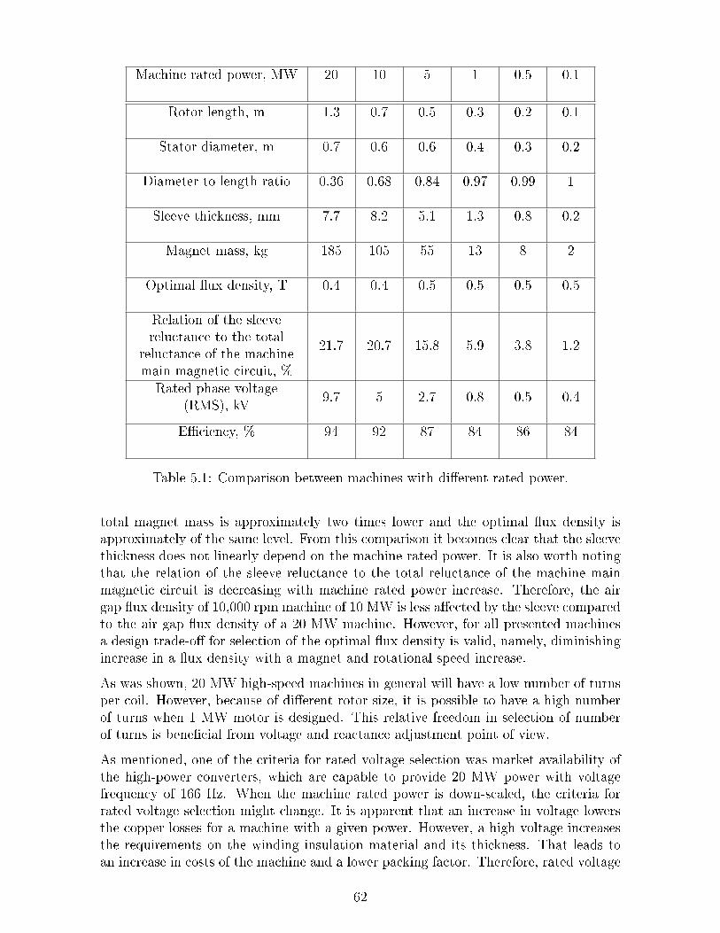
Machine rated power, MW 20 10 5 1 0.5 0.1
Rotor length, m 1.3 0.7 0.5 0.3 0.2 0.1
Stator diameter, m 0.7 0.6 0.6 0.4 0.3 0.2
Diameter to length ratio 0.36 0.68 0.84 0.97 0.99 1
Sleeve thickness, mm 7.7 8.2 5.1 1.3 0.8 0.2
Magnet mass, kg 185 105 55 13 8 2
Optimal ux density, T 0.4 0.4 0.5 0.5 0.5 0.5
Relation of the sleevereluctance to the total
reluctance of the machinemain magnetic circuit, %
21.7 20.7 15.8 5.9 3.8 1.2
Rated phase voltage(RMS), kV
9.7 5 2.7 0.8 0.5 0.4
Eciency, % 94 92 87 84 86 84
Table 5.1: Comparison between machines with dierent rated power.
total magnet mass is approximately two times lower and the optimal ux density isapproximately of the same level. From this comparison it becomes clear that the sleevethickness does not linearly depend on the machine rated power. It is also worth notingthat the relation of the sleeve reluctance to the total reluctance of the machine mainmagnetic circuit is decreasing with machine rated power increase. Therefore, the airgap ux density of 10,000 rpm machine of 10 MW is less aected by the sleeve comparedto the air gap ux density of a 20 MW machine. However, for all presented machinesa design trade-o for selection of the optimal ux density is valid, namely, diminishingincrease in a ux density with a magnet and rotational speed increase.
As was shown, 20 MW high-speed machines in general will have a low number of turnsper coil. However, because of dierent rotor size, it is possible to have a high numberof turns when 1 MW motor is designed. This relative freedom in selection of numberof turns is benecial from voltage and reactance adjustment point of view.
As mentioned, one of the criteria for rated voltage selection was market availability ofthe high-power converters, which are capable to provide 20 MW power with voltagefrequency of 166 Hz. When the machine rated power is down-scaled, the criteria forrated voltage selection might change. It is apparent that an increase in voltage lowersthe copper losses for a machine with a given power. However, a high voltage increasesthe requirements on the winding insulation material and its thickness. That leads toan increase in costs of the machine and a lower packing factor. Therefore, rated voltage
62

selection can be another design trade-o for 1 MW machine.
To determine rated voltage for a specic rated power, the same reasoning, as it wasfor selection of diameter/length ratio, can be applied. The rated voltage of 20 MWmachine is taken as an upper limit and the lower limit is dened as equal to 690 Vline-to-line. The voltage of the machine with the rest rated power will be interpolated.
It is important to keep in mind, that an important input parameter for the motor designis the duty cycle of the propulsion application. A low-speed bulk container requires fullpower most of the time while a typical city cycle of a vehicle is sharp and the full poweris required only during acceleration. When the motor is used in a full-power moderelatively rare from the point of view of operational prole,the motor can be designedin such a way to provide a peak power only in overload mode. Practically, in an overloadmode electrical motors can operate at double rated power for a short time, albeit thatthe overload capability mainly depends on the thermal capabilities.
5.2 Conclusion
This chapter describes the dierences between design challenges of machines with dier-ent rated power. It was shown how the design trade-os are inuenced by the machinerated power and speed, and how the geometrical data deviates for dierent machinedesigns.
A criterion for the selection of diameter to length ratio for dierent machine ratedpower was described and machines with rated power from 20 MW till 100 kW wereanalyzed. It was calculated that for the same rotational speed, machine of less powerneeds thinner magnet enclosure. The relation of the magnet enclosure reluctance tothe total reluctance of the machine main magnetic circuit is less for the machines ofless power and, therefore, magnet enclosure design is not critical for the low-powermachines.
To compare a design of 20 MW machine with 100 kW machine, one should refer toTables 5.2, 5.3 and 5.4, which represent data calculated for the proposed design of 100kW machine.
63
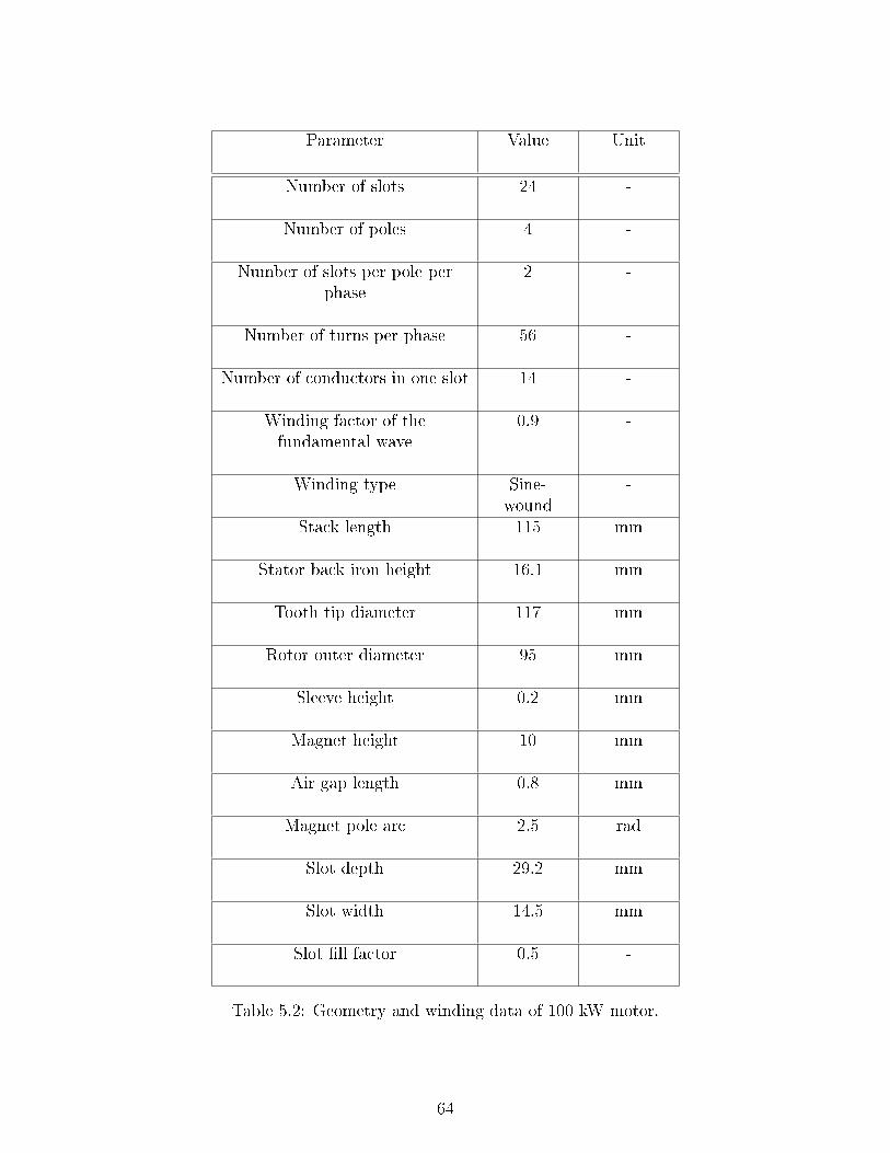
Parameter Value Unit
Number of slots 24 -
Number of poles 4 -
Number of slots per pole perphase
2 -
Number of turns per phase 56 -
Number of conductors in one slot 14 -
Winding factor of thefundamental wave
0.9 -
Winding type Sine-wound
-
Stack length 115 mm
Stator back iron height 16.1 mm
Tooth tip diameter 117 mm
Rotor outer diameter 95 mm
Sleeve height 0.2 mm
Magnet height 10 mm
Air gap length 0.8 mm
Magnet pole arc 2.5 rad
Slot depth 29.2 mm
Slot width 14.5 mm
Slot ll factor 0.5 -
Table 5.2: Geometry and winding data of 100 kW motor.
64

Parameter Value Unit
Output power 100 kW
Shaft torque 95 Nm
Base speed 10,000 rpm
Air gap shear stress 39 kN/m2
Back EMF, RMS 358 V
Phase voltage, RMS 2042 V
Phase current, RMS 137 A
Phase voltage fundamentalfrequency
333 Hz
Electric loading 37 kA/m
Current density 8713 kA/m2
Air gap average ux density atopen conditions
0.5 T
Power factor 0.17 -
Table 5.3: Load data of 100 kW motor.
65
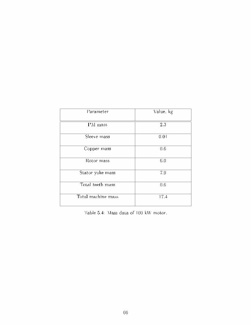
Parameter Value, kg
PM mass 2.3
Sleeve mass 0.01
Copper mass 0.6
Rotor mass 6.0
Stator yoke mass 7.9
Total teeth mass 0.6
Total machine mass 17.4
Table 5.4: Mass data of 100 kW motor.
66

Chapter 6
Application of High-Speed Motors on
Vessels
In the previous chapters the benets of electrical motors as drives were described andanalyzed. The main challenges of a high-speed permanent magnet motor design werepresented and investigated. However, the important topic, which has not been coveredyet by this report, is what conguration of a vessel drivetrain employs better advantagesof a high-speed electrical motor. In this chapter, eciency and implementation of ahigh-speed electrical propulsion on vessels are investigated.
6.1 Propeller basics
Up to date, screw propeller is the most commonly used type of propulsor. Although a lotof dierent types of unconventional propulsors are under research for more than decades,for most of the applications propellers still have no competitors [53, 54]. Seemingsimplicity of a propeller as a mechanical device may allow one to conclude that it is atrivial task to estimate eciency of a dierent propeller arrangement. This conclusionis misleading, so as propeller design requires accurate assessment of the ambient uidbehavior, which is much dependent on the vessel hull shape. Thus, in general, propellersare designed specically for a particular vessel.
Though a propeller design requires knowledge in naval technology and uid dynamics,there are a few basic principles which should be mentioned. The highest eciency ofthe propeller operation is reached when it is located behind the hull. When ship moves,it drags water around the hull in the direction of its movement. Velocity of the wateron the hull surface is almost equal to the ship speed while it becomes zero at a certaindistance from the hull. As a consequence, velocity of the wake at a propeller surface isnon-zero and depends on the hull shape and propeller location. The kinematic energy,transmitted by the hull to the wake is extracted by the propeller, which stipulates itslocation in the vessel stern.
In general, distribution of the water velocity along propeller surface is non-homogenous,which increases the risk of propeller cavitation. Cavitation is highly undesirable eect,which causes vibration and propeller destruction. Dierent mechanical means, such as
67

Figure 6.1: POD conguration with two propellers, rotating at dierent speeds. It isworth noting, that sizes of the motors, which drive propellers are also dierent accordingto the rated speeds.
nozzles, ducts and ns are used to make water ow more homogenous. However, theeect of these components is not always positive and should be investigated in detailsspecically for the ship where it is going to be installed.
The vessel hull shape is designed in such a way to keep the ship's resistance as lowas possible. To decrease the wave resistance, the upper water part has a sharp shapewith clearly visible wave breaking line. To decrease wave generation, dierent typesof bulbs are applied, while to decrease the drag resistance of the underwater part, thehull prole is made smooth and without any abrupt geometrical elements. The latteris also valid for the propulsors and it is a reason why PODs have a streamlined shape.
To extract most of the energy, contained in a vessel wake, a conguration of a PODwith double propeller can be employed (Fig. 6.1). In such conguration, a low-speedpropeller accelerates the water stream, thus increasing operational eciency of a high-speed propeller.
As was mentioned, the power required to propel ship and the propeller rotational speedmuch dependent on the vessel hull shape. However, it is clear that propeller rotationalspeed also depends on the required vessel speed. It is also apparent that propellerrotational speed is much dierent if to compare heavy low-speed cargo carriers andracing boat. Though recently introduced concepts, such as fast ferry, might be a topicof economic studies in further, most of modern heavy vessels are low-speed (Table 6.1).So as it is a strong dependence of propeller speed on the vessel speed, it is clear thathigh-speed electrical motors that drive propellers directly would be mostly demandedonly on high-speed vessels. For low-speed vessels electrically propelled drivetrain shouldinclude gearbox to match the propeller speed with the motor speed.
68

Vessel type Top speeds
Bulk carriers 16
LNG tankers 25
Fast displacement ships 25
Passenger vessels 30
Navy 40
High-speed crafts >60
Table 6.1: Typical top speeds of dierent types of vessels [53].
6.2 Supercavitating propellers
Propeller maximum rotational speed is limited by the cavitation eect. Cavitation is asubject of the numerous studies which have been carrying out since second half of the20th century. Cavitation occurs in any situation where uid moves near the solid surface[55]. Because of local high uid velocities, local pressure of liquid portions becomes lowenough for the uid to change its state [53, 55]. As a consequence, cavitation bubbles,lled with vapor, appear. When there is a rather high amount of bubbles appearing ata small distance near each other, they start to interact and will form cloud cavitation.After cavitation bubbles arrive to the area with high pressure, they collapse. Becausebubble collapses asymmetrically, a microjet inow appears on its one internal side. Thismicrojet reaches very high velocities and its impact on the opposite side of a bubblegenerates a shock wave which is transmitted to the solid surface [55], producing noiseand material erosion.
Cavitation is unavoidable eect which occurs at any speed of propeller rotation. How-ever, when the speed is higher, the damage, caused by cavitation to the propeller bladesis stronger. There were attempts to design non-cavitating propeller by varying its ge-ometry, however, these attempts did not show positive results [56]. The other approachto decrease cavitation negative inuence was design of a propeller, which operates inthe regime of a supercavitation (SC). In such a regime, the cavities collapse behind theblade surface, causing much less damage to the propeller. During 60-80s a few high-speed hydrofoil crafts with SC propellers were manufactured and commercially used.As it is dated by [56], the latest of the hydrofoil ships showed insucient reliability ofthe shaft sealing. This disadvantage of the SC propellers appeared to be a crucial oneand the further open ocean hydrofoil ships were equipped with water jets.
However, despite the clear end of the SC propellers era in the mid of 80s, there are fur-ther modications, namely surface-piercing, transcavitating propellers and ventilatedwater jets are to date subjects of ongoing research. Fig. 6.2 illustrates the interdepen-
69

dence between craft speed, its displacement and type of installed propeller. Apparently,high-speed vessels which employ surface-piercing propellers probably are the most at-tractive market candidates for electrical high-speed direct-driven drivetrains.
Figure 6.2: Interdependence between craft speed, propeller speed and craft displacement[57].
6.3 Water jet
The other type of drivetrain, which employs high-speed propulsor is a water jet. Awater jet comprises a pump, which sucks uid at the inlet and generates a jet at theoutlet. A high-speed jet accelerates vessel. Because pump jets are much more ecientat the high speeds, they are mainly employed on high-speed crafts.
Ones of the largest world manufacturers of water pump jets are Wartsilla and Rolls-Royce. According to the published data, the power of the largest installed Wartsillajets reaches 20 MW and water jets up to 50 MW available by request. The crucialcomponent of the water jet, which creates the pressure dierence between the inletand the outlet, nally resulting in the jet acceleration, is an impeller. An impelleris installed inside a diusor, which is fundamentally a pipe at the intake side with anopen end (Fig. 6.3). In conventional systems impeller is driven directly by diesel engineor gas turbines via shaft, which is located partly in diusor, creating an obstacle forthe water ow. Such location of the diusor causes cavitation and increases level ofnon-homogeneity of the intake water ow. Therefore, removing the shaft might gaineciency of a water jet propulsion systems.
Generally, the water jet sizing requires data about the hull resistance, demanded thrustand vessel speed. According to Wartsilla datasheet, the speed of impeller rotation liesin the range of several hundred's till several thousand's rpm. Based on the mentioned
70

Figure 6.3: X-ray view of a water jet, produced by Wartsilla [58].
above, it is likely that high-speed electrical motors with internal impeller can be e-ciently used in water jets. Such conguration will not require a shaft and can benetfrom the earlier discussed advantages, brought by high-speed motor. A sketch of suchconguration is represented in Fig. 6.4
Figure 6.4: Sketch of a water jet with direct-drive high-speed electrical motor.
The other possible type of propulsor is a water track, illustrated in Fig. 6.5. The mainadvantage of a water track is a constant thrust in forward direction, which is achievedby adjusting blade position. Contrary to conventional propellers, which normally createcertain lift in upward direction, operation of water track can be more ecient.
Figure 6.5: Sketch of a water track.
71
Chapter 7
Conclusions and Future Work
The main driving factors for marine propulsion units are low mass and volume, lownoise and vibration, and reliability. With these performance drivers in mind, multi-parametric scans of the salient geometric parameters, gear ratios and pole numbers havebeen initiated in this rst part of the concept study using advanced computational tools.This is supported in turn by empirical data from detailed knowledge about non-linearmechanics, electromagnetics, thermodynamics, etc. that has been acquired with byyears of electric drive experience. Further, the combination of modern power electronicswith these high-speed propulsion machines oers a huge advantage for propulsion inbeing compact and providing for an ecient structure. This is enabled by the recentadvances in IGBT power switching devices that allow for higher system voltages andhence minimization of interconnection cable mass on the ship.
Further, the obtained results show that in spite of challenges, posed by rotational speedand large power, 20 MW high-speed permanent magnet synchronous motor is feasibleand oers the required compactness and eciency. To calculate a motor design, analgorithm was developed and implemented in Matlab. Calculation results showed thatestimated rotor mass is less than 1.5 tonnes and the total machine mass is less than 5tonnes. That satises the initial project requirements to the machine compactness. Themaximal speed which can be reached by 20 MW PMSM is estimated as 10,000 rpm.To restrain high centrifugal force experienced by magnets, a carbon sleeve is calculatedas 5 to 10 mm. The optimum ux density of the designed motor is around 0.45 T andthe shear stress about 50 kN/m2. The most important characteristics of the proposedmotor design are presented in Tables 4.2, 4.3 and 4.4.
In a rst-order approximation, the mass of a 20 MW mechanical gearbox with inputspeed of 10,000 rpm and gear ratio of 1:66 is calculated as 25 tonnes while the totalmass of the magnetic gearbox with the same characteristics is calculated as 40 tonnes.Therefore, mass of the combination of the high-speed motor and gearbox is expected tobe less than 30 tonnes when mechanical gearbox is employed, and less than 40 tonneswhen magnetic gearbox is used. For comparison, the mass of the propulsion module ofAzipod XO2100, produced by ABB, is 170 tonnes for output power of 18 MW [23].
The most prospective use of directly-connected high-speed motor for marine propulsionis to employ the motor in a water jet drivetrain. Replacement of a shaft-driven impellerwith a high-speed electrical machine might gain increase in the hydrodynamic eciency
72

and fuel savings of the propulsion unit. Initially it was assumed that such solution mightbe patented. However, after the report was submitted to the customer, it was foundthat a solution for a water jet, which is very similar to the proposed in this report, hadalready been patented before. Nevertheless, the rest of the proposed congurations canbe used for further in-depth research on this topic.
To perform detailed analysis of the proposed in this project motor design and drivetrainconguration, additional multi-disciplinary studies are required in future. Althoughit is estimated that an application of a high-speed motor will greatly contribute tothe compactness and eciency of modern marine propulsors, only simulations of thecomplete ship power system and drivetrain will provide a denite answer about theadvantages of high-speed PMSM use. After more detailed research on such topics asselection of prime movers, power electronics and control system design, assessment ofhydrodynamic eciency, a prototype of a high-speed motor can be built for performingmeasurements. If the measured results correspond to the simulations, a propulsor modeltesting in basin should be performed.
The enormous technological potential of this conceptual high-speed electrical propulsionsystem, due to high power density of both power electronics and electrical motor, willprovide a cost-eective electrical drive system for future marine applications. Althoughthis report only scratched the surface of the required multi-disciplinary research, itsupports this statement.
It is expected that the results of the performed work will be further published.
73
Bibliography
[1] Reference list LNG carriers electric power and propulsion systems, ABB AS Marineand Turbocharging, 2010.
[2] Abb wins 18 million order for subsea pipeline construction vessels, Avail-able: http://www.abb.com/cawp/seitp202/6cbd0102e403ad1285257a0000524030.aspx, 2012.
[3] Samsung chooses stadt no-loss electric propulsion, Available: http://www.stadt.no/pdf/STADT_SAMSUNG%20ENGLISH%20PR%20REV2.pdf, 2011.
[4] C. Bailey, D. Saban, and P. Guedes-Pinto, Design of high-speed direct-connectedpermanent-magnet motors and generators for the petrochemical industry, Indus-try Applications, IEEE Transactions on, vol. 45, no. 3, pp. 11591165, May-June2009.
[5] M. Bogomolov, C. Kral, A. Haumer, and E. Lomonova, Modeling of permanentmagnet synchronous machine with fractional slot windings, in IECON 2012 -38th Annual Conference on IEEE Industrial Electronics Society, Oct. 2012, pp.18941899.
[6] C. Kral, A. Haumer, M. Bogomolov, and E. Lomonova, Harmonic wave modelof a permanent magnet synchronous machine for modeling partial demagnetiza-tion under short circuit conditions, in Electrical Machines (ICEM), 2012 XXthInternational Conference on, Sept. 2012, pp. 295301.
[7] http://www.autodesk.nl.
[8] Diesel-electric drives, MAN, Copenhagen, Denmark.
[9] M. R. Patel, Shipboard propulsion, power electronics, and ocean energy. CRCPress, 2012.
[10] B. A. Bassham, An evaluation of electric motors for ship propulsion, Ph.D. dis-sertation, Naval Postgraduate School, Monterey, California, 2003.
[11] I. R. J. King, Marine propulsion: the transport technology for the 21st century?,Rolls-Royce.
[12] ABB marine catalogue, ABB Oy Marine, 2008.
[13] Wartsila ship product catalogue, Wartsila, 2011.
74
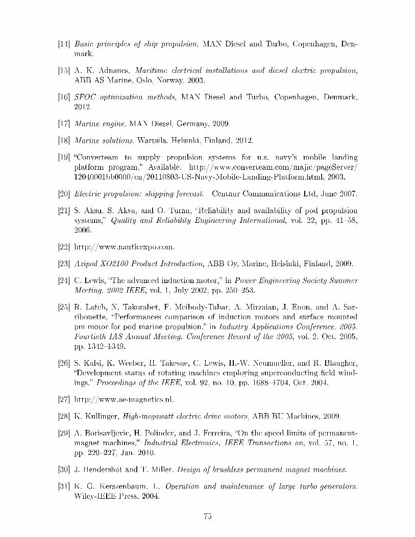
[14] Basic principles of ship propulsion, MAN Diesel and Turbo, Copenhagen, Den-mark.
[15] A. K. Adnanes, Maritime electrical installations and diesel electric propulsion,ABB AS Marine, Oslo, Norway, 2003.
[16] SFOC optimization methods, MAN Diesel and Turbo, Copenhagen, Denmark,2012.
[17] Marine engine, MAN Diesel, Germany, 2009.
[18] Marine solutions, Wartsila, Helsinki, Finland, 2012.
[19] Converteam to supply propulsion systems for u.s. navy's mobile landingplatform program, Available: http://www.converteam.com/majic/pageServer/12040001bb0000/en/20110803-US-Navy-Mobile-Landing-Platform.html, 2003.
[20] Electric propulsion: shipping forecast. Centaur Communications Ltd, June 2007.
[21] S. Aksu, S. Aksu, and O. Turan, Reliability and availability of pod propulsionsystems, Quality and Reliability Engineering International, vol. 22, pp. 4158,2006.
[22] http://www.nauticexpo.com.
[23] Azipod XO2100 Product Introduction, ABB Oy, Marine, Helsinki, Finland, 2009.
[24] C. Lewis, The advanced induction motor, in Power Engineering Society SummerMeeting, 2002 IEEE, vol. 1, July 2002, pp. 250253.
[25] R. Lateb, N. Takorabet, F. Meibody-Tabar, A. Mirzaian, J. Enon, and A. Sar-ribouette, Performances comparison of induction motors and surface mountedpm motor for pod marine propulsion, in Industry Applications Conference, 2005.Fourtieth IAS Annual Meeting. Conference Record of the 2005, vol. 2, Oct. 2005,pp. 13421349.
[26] S. Kalsi, K. Weeber, H. Takesue, C. Lewis, H.-W. Neumueller, and R. Blaugher,Development status of rotating machines employing superconducting eld wind-ings, Proceedings of the IEEE, vol. 92, no. 10, pp. 16881704, Oct. 2004.
[27] http://www.ae-magnetics.nl.
[28] K. Kullinger, High-megawatt electric drive motors, ABB BU Machines, 2009.
[29] A. Borisavljevic, H. Polinder, and J. Ferreira, On the speed limits of permanent-magnet machines, Industrial Electronics, IEEE Transactions on, vol. 57, no. 1,pp. 220227, Jan. 2010.
[30] J. Hendershot and T. Miller, Design of brushless permanent-magnet machines.
[31] K. G. Kerszenbaum, I., Operation and maintenance of large turbo-generators.Wiley-IEEE Press, 2004.
75

[32] Z. Kolondzovski, A. Arkkio, J. Larjola, and P. Sallinen, Power limits of high-speed permanent-magnet electrical machines for compressor applications, EnergyConversion, IEEE Transactions on, vol. 26, no. 1, pp. 7382, Mar. 2011.
[33] K. Binns and D. Shimmin, Relationship between rated torque and size of perma-nent magnet machines, Electric Power Applications, IEE Proceedings -, vol. 143,no. 6, pp. 417422, Nov. 1996.
[34] J. Pyrhönen, T. Jokinen, and V. Hrabovcová, Design of rotating electrical ma-chines. Wiley, 2008.
[35] K. Weeber, Advanced electric machines technology, GE Global Research, 2009.
[36] J. Bone, Inuence of rotor diameter and length on the rating of induction motors,Electric Power Applications, IEE Journal on, vol. 1, no. 1, pp. 26, Febr. 1978.
[37] ROBICON perfect harmony - the leading medium-voltage drive, Siemens AG In-dustry Sector, 2009.
[38] G. Slemon, On the design of high-performance surface-mounted pm motors, In-dustry Applications, IEEE Transactions on, vol. 30, no. 1, pp. 134140, Jan.-Febr.1994.
[39] Private interview with Dr. F.J.M. Thoolen at CCM, June 2013.
[40] A. Grauers and P. Kasinathan, Force density limits in low-speed pm machinesdue to temperature and reactance, Energy Conversion, IEEE Transactions on,vol. 19, no. 3, pp. 518525, Sept. 2004.
[41] A. Boglietti, A. Cavagnino, and D. Staton, Determination of critical parametersin electrical machine thermal models, Industry Applications, IEEE Transactionson, vol. 44, no. 4, pp. 11501159, July-Aug. 2008.
[42] P. Mellor, D. Roberts, and D. Turner, Lumped parameter thermal model forelectrical machines of tefc design, Electric Power Applications, IEE ProceedingsB, vol. 138, no. 5, pp. 205218, Sept. 1991.
[43] J. Paulides, High performance 1.5mw 20,000rpm permanent-magnet generatorwith uncontrolled rectier for 'more-electric' ship, Ph.D. dissertation, Departmentof Electronic and Electrical Engineering, University of Sheeld, Sheeld, UnitedKingdom, 2005.
[44] J. Linni, Design, analysis and application of coaxial magnetic gears, Ph.D. dis-sertation, Department of Electrical and Electronic Engineering, The University ofHong Kong, Pokfulam, Hong Kong, 2010.
[45] D. Hofmann, Gearing for high speed motors, in High Speed Bearings for ElectricalMachines (Digest No: 1997/164), IEE Colloquium on, Apr. 1997, pp. 301313.
[46] Gearbox technical information GPV 500D, Rexroth Bosch Group.
[47] G. Maitra, Handbook of gear design. Tata McGraw-Hill, 1994.
76

[48] J. Shigley, C. Mischke, and T. Brown, Standard handbook of machine design, ser.McGraw-Hill Standard Handbooks. McGraw-Hill, 2004.
[49] H. Merritt, Gear engineering, ser. A Halsted Pr. Book. Wiley, 1971.
[50] P. Lynwander, Gear drive systems: design and application, ser. Dekker MechanicalEngineering Series. Marcel Dekker, 1983.
[51] K. Atallah and D. Howe, A novel high-performance magnetic gear, Magnetics,IEEE Transactions on, vol. 37, no. 4, pp. 28442846, Jul. 2001.
[52] E. Gouda, S. Mezani, L. Baghli, and A. Rezzoug, Comparative study between me-chanical and magnetic planetary gears, Magnetics, IEEE Transactions on, vol. 47,no. 2, pp. 439450, Feb. 2011.
[53] G. Kuiper, Lectures: resistance and propulsion, Technical University Delft, theNetherlands.
[54] Private interview with prof. Dr. ir. van Terwisga at MARIN, Oct. 2013.
[55] P. Randall W. Whitesides, Interesting facts (and myths) about cavitation, PDHCenter.
[56] A. Achkinadze, Supercavitating propellers, Saint-Petersburg State Marine Techni-cal University, Russia.
[57] B. R. Blount, D.L., Design of propulsion systems for high-speed craft, MarineTechnology and SNAME News, vol. 34, no. 4, pp. 276292, 1997.
[58] Wartsila propulsors, Wartsila, Helsinki, Finland, 2011.
77

Appendix A
Baseline Document
Review-versions
Due to the unforeseen reasons, which are out of the scope of this report, the projectmanagement of this project was done after the actual nalization of the project. How-ever, the project management document was under development for more than onemonth and, therefore, the nal version was greatly improved compared to the initialone. Through a number of revisions some modications were made. The most impor-tant ones are:
1. Introduction: was modied to focus on the description of the project backgroundand give better clarity to those not acquainted with the topic.
2. The project result: denition, results and delimiters were modied for a few timesfor the sake of clarity.
3. Activities in each project phase: strategy was introduced, which led to smootheradaption of the tasks. The separation of the tasks is now better distributed ineach phase.
4. Control plan: time assignment for each phase and task varied signicantly through-out the project and the revision of this report. Gantt chart with margins wasadded. Information about budgets and spending were acquired. Quality controlwas extended with more explicit details.
1. Introduction
Electrical propulsion in the marine sector is an emerging technology which has beenunder development since the beginning of the last century. Though nowadays electricalpropulsion is considered a standard for cruise ships and is ever more implementedon icebreakers, service vessels (aeronautic, research, pipe-laying) and oshore drillingplatforms, it is still a challenging area, which stimulates research of more ecient electricdrives and dierent drivetrain congurations which can be applied in dierent marineapplications.
78

Customer is a research and development company, which is mainly focused on the devel-opment of intellectual property, testing and certication of diverse electric apparatuses.The company is actively being searching for disruptive electrical technologies in dier-ent areas. Though large part of customer's business is connected with the automotiveelectrical applications, the company is also interested in the development of new typesof marine electrical propulsors, which can bring signicant benets for the ship own-ers. Proposed by the assistant professor from Electromechanics and Power ElectronicsGroup, Dr. Johan Paulides, a new concept for electrical ship propulsion, which em-ploys high-speed permanent magnet synchronous machine (PMSM), was accepted bythe customer and became a main topic of this project.
The aim of this project is to give a general introduction to the concept of electrically-propelled vessels and present a feasibility study of 20 MW high-speed PMSM to be usedfor ship propulsion. This project is executed as the nal project of the ProfessionalDoctorate in Engineering (PDEng) in Information and Communication Technology, atwo years program that is oered by the Stan Ackermans Institute (SAI) at TU/e. Thesupervisors of the project are Dr. Johan Paulides and Dr. Alexandar Borisavljevic fromthe EPE Group, TU/e.
2. The project result
2.1. Problem denition
The demand for compact and ecient electrical drives has created an opportunity forhigh-speed permanent magnet synchronous motors (PMSM) use for ship propulsion.In order to assess a feasibility of a chosen concept, one may need to investigate powerlimits of high-speed machines, design challenges and possible solutions. Therefore, thepresent project is focused on investigation of 20 megawatt (MW) electric drive, wherethe system constraints for marine propulsion will be considered. The outcome of theproject will constitute a concept study and not an in-depth system analysis that wouldbe required when implementing this technology for an electrical drive in future ships.
2.2. Results
The expected result of the project is a feasibility study of a high-speed high-powerelectrical motor for ship propulsion. Thus, the main outcome is:
Report.
Presentation.
2.3. Deliverables
The nal report should include the following topics:
Analysis of potential benet brought by implementation of electrical propulsionon vessel.
79

The conceptual design of high-speed electrical motor and its major operationaland geometrical characteristics.
The comparison between high-speed motors with dierent rated power.
Gearbox assessment and approximate calculation.
The overview of possible drivetrain layouts which employ high-speed electricalmotors.
Proposal for new types of propulsors and short description of the advantagesbrought by the proposed conguration.
2.4. Delimiters
The outcome report will constitute only a concept design. In this respect, onlythe main challenges of high-speed high-power machine will be investigated, whichmeans that the calculated motor parameters should be used only as guidelines forfurther, in-depth research.
The thermal behavior of the motor is out of consideration.
The hydrodynamics of the possible propulsors with high-speed electrical motorsis not investigated.
Propeller design and ship's wake modeling are not investigated.
3. Project activities
3.1. Strategy
Depending on the goal and deliverable results project can be divided in dierent phases.Apparently when the main outcome of a project is a product of any type and the projectstarts from scratch, all the activities performed during the project can be dividedinto six phases, namely initial, denition, design, preparation, realization and follow-upphase. However, the main goal of the current project is a feasibility study and concep-tual design, therefore, the project itself can be considered as a design phase of somelarger project. The other way to divide current project into phases is to think about themain goal, as about a process, which has six mentioned phases. However, because suchan approach will inevitably bring complexity and vagueness in dening activities thatshould be performed in each phase, the following strategy was used. As was mentioned,the nal report is the main outcome of the study. The rst, second and third chaptersof the nal report introduce the concept of electrical propulsion on ships and denemain challenges of the high-speed machine implementation. Therefore, from the pointof view of project management, these chapters describes the activities performed duringthe denition phase. The fourth and fth chapters investigate the challenges of a 20MW motor design and possible solutions. In this respect, the content of these chapterscorrespond to the design phase of the project. The sixth chapter contains information
80

relevant for the realization phase of the project, namely implementation of the high-speed motors on ships and possible congurations of propulsors. A preparation andfollow-up phases are skipped because of absence of the corresponding activities.
3.2. Initiation phase
Activities:
Compose technical proposal.
Dene desired results and requirements.
End:
Project assignment.
3.3. Denition phase
Activities:
Discuss with supervisors possibilities of application of high-speed permanent mag-net motors on vessel.
Share experience and review the work which was done by supervisors in similarareas.
Dene the requirements to the drive systems of large vessels.
Dene what types of propulsors are investigated.
Explore the benets and drawbacks of electrical propulsion on ships.
Review modern types of vessel propulsion.
Identify challenges of future propulsion systems.
Estimate benets of electrical propulsion on vessels.
Make an overview of types of electrical motors which are used for ship propulsion.
Make an overview of 20 MW high-speed motor design challenges.
Dene rated rotational speed and power of investigated motor.
End:
Chapters 1, 2 and 3 of the nal report.
81

3.4. Design phase
Activities:
Comprehensive analysis of datasheets issued by the main manufacturers of elec-trical motors and diesel engines for the marine industry.
Calculation of magnetic and electric loading.
Selection of rotor to length ratio for 20 MW high-speed permanent magnet motor.
Calculation of rotor sleeve thickness.
Selection of optimal magnet thickness.
Determining number of slots of a motor.
Modeling of thermal behavior of the motor.
Calculation of gearbox dimensions.
Comparison of calculated motor parameters for dierent power ratings.
End:
Chapters 4 and 5 of the nal report.
3.5. Realization phase
Activities:
Determination of new conceptual propulsor's congurations.
End:
Chapter 6 of the nal report.
4. Control plan
4.1. Time
4.1.1 Control of progress
Short weekly meetings with supervisor in TU/e.
82

Title Date
Starting date of the project 01.04.2012Completing date of the project 30.11.2012
Initial phase duration 1 weekDenition phase duration 2 months 3 weeksDesign phase duration 6 months
Delivery date for the results 30.11.12Final presentation To be determined
Project participant Man hours
Capacity Maxim Bogomolov 40 hours/weekCapacity - TU/e supervisor 10 hours/month
Table A.1: Overview of time/capacity.
In the Gantt chart, presented in the end of the document, the timeline of theproject is shown. Three vertical red lines indicate important deadlines submit-ting of the preliminary report, submitting of the nal report and submitting ofthe improved version of the nal report, according to the remarks, obtained fromthe customer. August, 24th was agreed as a date of preliminary report submit-ting. The preliminary report should consist of not less than 20 pages and containinformation about performed work at the moment of submitting. November 30this the date when nal report was submitted and the hard copy of the improvedversion of the nal report was send to the customer on December, 20th.
Approximately one presentation per 3 weeks was prepared. The rst presentationfor customer was shown on August, 24th, during the one-day visit of the cus-tomer's director to Eindhoven. On 18th December, the nal teleconference withdiscussion of the achieved results was held.
4.2. Money
The costs involved in the project include:
TU/e budget for PDEng candidates.
The project fee, paid by the customer to TU/e.
The expected revenues (in long run) to the customer after selling the developedtechnology or patents, if such will be arranged.
TU/e has calculated the overall value of a 2-year PDEng Traineeship to be 250.000¿including tuition fees, trainings, salaries and oce/equipment costs. The cost of theproject for the principal is condential and can not be mentioned in this report. How-ever, it should be noted, that this amount is paid by the customer to TU/e for Maxim'swork. Even rough estimation of possible revenues, brought by implementation of theproposed concepts and its introduction in the market of the marine propulsion systems,requires time consuming nancial studies and calculation, which because of apparent
83
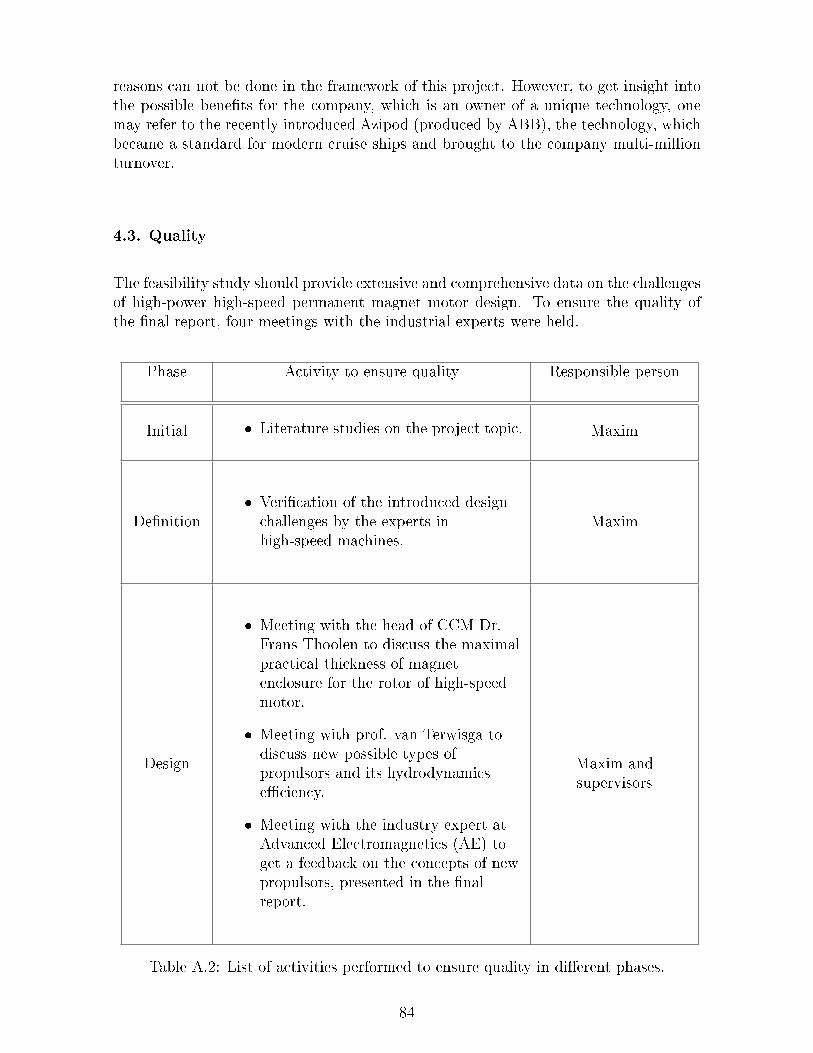
reasons can not be done in the framework of this project. However, to get insight intothe possible benets for the company, which is an owner of a unique technology, onemay refer to the recently introduced Azipod (produced by ABB), the technology, whichbecame a standard for modern cruise ships and brought to the company multi-millionturnover.
4.3. Quality
The feasibility study should provide extensive and comprehensive data on the challengesof high-power high-speed permanent magnet motor design. To ensure the quality ofthe nal report, four meetings with the industrial experts were held.
Phase Activity to ensure quality Responsible person
Initial Literature studies on the project topic. Maxim
Denition Verication of the introduced designchallenges by the experts inhigh-speed machines.
Maxim
Design
Meeting with the head of CCM Dr.Frans Thoolen to discuss the maximalpractical thickness of magnetenclosure for the rotor of high-speedmotor.
Meeting with prof. van Terwisga todiscuss new possible types ofpropulsors and its hydrodynamicseciency.
Meeting with the industry expert atAdvanced Electromagnetics (AE) toget a feedback on the concepts of newpropulsors, presented in the nalreport.
Maxim andsupervisors
Table A.2: List of activities performed to ensure quality in dierent phases.
84

4.4 Information
Phase Document Produced by Recipient
Initial Project assignment Supervisors MaximDenition Project plan Maxim and
supervisorsMaxim andsupervisors
Design Preliminary report,presentations
Maxim Supervisors
Realization Final report, nalpresentation
Maxim Supervisors,principal
Table A.3: Information exchange in dierent phases.
5. Organization
Project owner.
Contractor: head of the EPE group, prof. Dr. Elena Lomonova.
Project leader: Dipl. Eng. Maxim Bogomolov.
TU/e Supervisor: Dr. Johan Paulides, Dr. Aleksandar Borisavljevic.
The working place of the author is located at EPE Group, TU/e.
Meeting with representatives of the customer that took place in Netherlands,Eindhoven, TU/e.
6. Risk analysis
6.1 Risk list
Risk Eect Chance Total Selection
Delay in performing of all initial phaseactivities
1 2 2
Slow progress because of the lack ofknowledge in non-prole for EPE
group subjects
2 2 4 X
Unavailability/unwillingness ofindustry experts in meetings
1 3 3
Table A.4: List of risks.
6.2 Risk management
Due to the nature of the project, namely only the assessment of possible solutionsfor electrical propulsion, it is rather dicult to identify any possible risks which can
85

break planned sequence of project activities. In general, main risks are connected withthe unexpected delay of performing all activities at the specic stage. As a result ofsuch delays, it might be that not all of the required topics are covered by the nalreport. To manage these kind of risks, two extra margins are added in planning: beforepreliminary and nal report. Due to the extra margins, the preliminary and nal reportswere delivered in time according to the initial schedule.
86
Figure A.1: Gannt chart.87