concept - smart desks · spring loaded concept roundtop rises from the surface for access to 4...
TRANSCRIPT
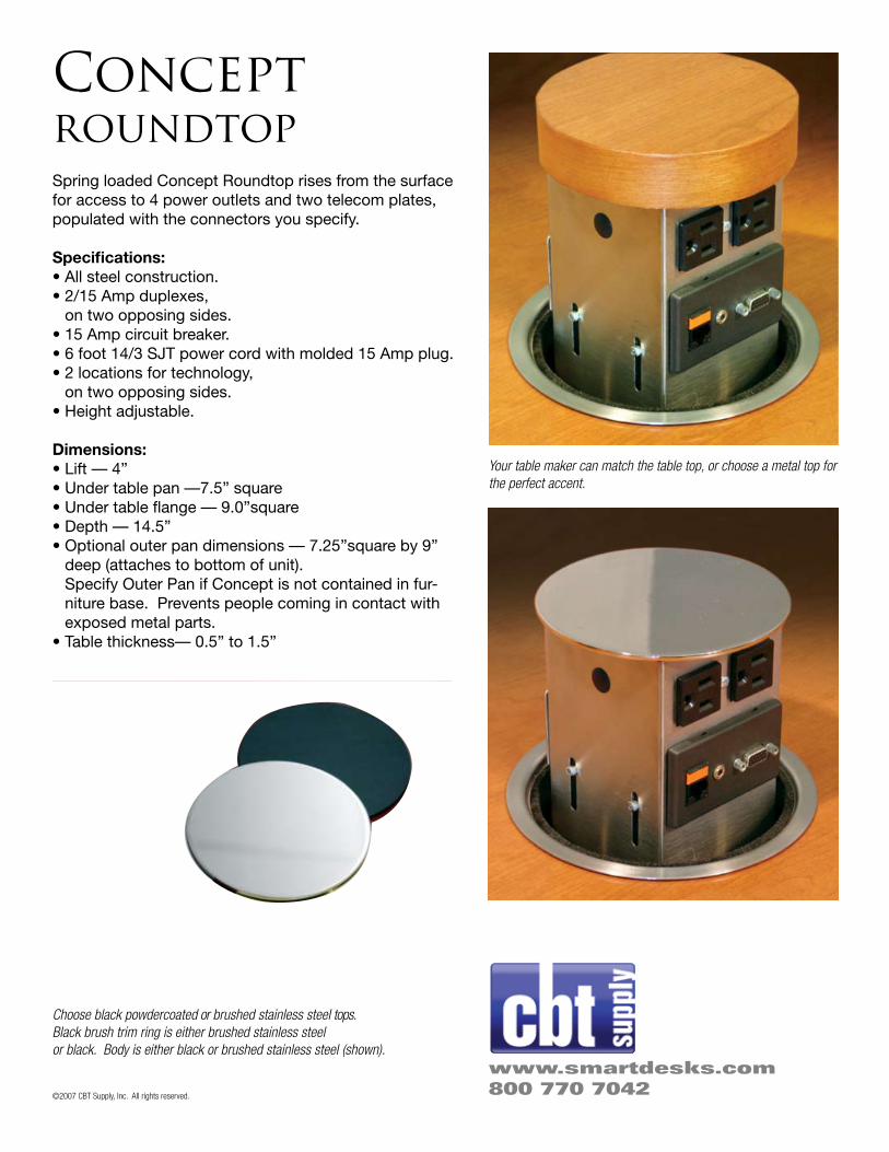
Spring loaded Concept Roundtop rises from the surface for access to 4 power outlets and two telecom plates, populated with the connectors you specify.
Specifications:• All steel construction.• 2/15 Amp duplexes,
on two opposing sides.• 15 Amp circuit breaker.• 6 foot 14/3 SJT power cord with molded 15 Amp plug.• 2 locations for technology,
on two opposing sides.• Height adjustable.
Dimensions:• Lift — 4”• Under table pan —7.5” square• Under table flange — 9.0”square• Depth — 14.5”• Optional outer pan dimensions — 7.25”square by 9”
deep (attaches to bottom of unit). Specify Outer Pan if Concept is not contained in fur-niture base. Prevents people coming in contact with exposed metal parts.
• Table thickness— 0.5” to 1.5”
Conceptroundtop
Your table maker can match the table top, or choose a metal top for the perfect accent.
Choose black powdercoated or brushed stainless steel tops.Black brush trim ring is either brushed stainless steel or black. Body is either black or brushed stainless steel (shown).
www.smartdesks.com800 770 7042©2007 CBT Supply, Inc. All rights reserved.

CONCEPTINSTALLATION SHEET
Round Application
Parameters Minimum top size: 5” Diameter* Maximum opening size: 7” Diameter* Manufactured top 5.25” Diameter*
Square Application
Parameters Minimum top size: 4.5” Square* Maximum opening size: 7” Square* Manufactured top 5.25” Square*
Step 1
Determine type of application and ensure table and top sizes fall within the parameters
Step 2
Fabricate top and cutout table as required. Ensure to allow for an adequate clearance between both
finished surfaces. Recommended gap is between 1/16” to 1/8”.
Step 3
Mount top onto Concept (if required) and mount
Concept under table as shown using #10 x ½
screws provided (ensure mounting screws don’t
penetrate table surface. Operate Concept to ensure
no interference between top and table occurs and
Concept functionsproperly.
Step 5
Feed Tel/Com wiring up through wire loop on leg and through grommet at
base of Concept. Hook up Tel/Com jacks and snap plates in place as shown.If Outer Pan is used, feed wires through opening at bottom before loop in leg.
Mount Outer Pan to Concept with screws
provided. Plug in Concept
Note:Ensure all adjustment
screws are tight and wires are not going to be
damaged during operation prior to use.
Concept is now ready for use.
Adjustment screws Two each side
Adjustment screws Two each side
Housing Assy
Housing Assy
Step 4 ADJUSTMENTS
To adjust for vertical: loosen the 4 screws on the side of
the housing and move housing to the desired
position. Holes in Inner Pan may assist in access to screws. Tighten screws.
To center top in opening: loosen 8 adjustment screws and center top in opening and tighten all 8 screws.
UNDERSIDE OF CONCEPT
Adjustment screws Qty 8
7.5” Sq.
6.0” Inner Pan
Access holes
Access holes
* When using manufactured tops or trim rings refer to those installation instructions for proper cutout sizes
No wires through center hole

Concept AK-00 & Trim Ring Installation Sheet
The AK-00 is designed to fit into a 7” x 7” cutout. Attach with four #8 screws through holes provided.
The Trim Ring fits into a 6” diameter cutout.Attach with two #8 screws through holes provided.

Concept
Table Requirements
Top Thickness
Table Thickness
It is very important that the Concept top thickness is the correct thickness or access to the data ports will be restricted.
Determining Recommended Top Thickness
1. Using the chart to the right find the table thickness on the bottom scale.
2. Move up the chart until you reach the first line, this is the minimum the top thickness can be.
3. Move further up the chart until you reach the next, solid, line. This is the maximum thickness the top can be.
4. Your finished top should fall between these two limits, for most cases it will be between 1/8” – 3/4”.
5. The upper, dotted, line represents the maximum thickness for the top if no data connections are needed.
Note: If a decorative metal plate is to be used as the Concept top, the following needs to be considered.
1. The plate thickness is 1/8” 2. The maximum table thickness is 1-1/4”.
Concept Top Thickness
0
1/8
1/4
3/8
1/2
5/83/4
7/8
1
1 1/8
1 1/4
1 3/8
1 1/2
5/8 3/4 7/8 1 1 1/8 1 1/4 1 3/8 1 1/2
Table Thickness (inch)
Con
cept
Top
Thi
ckne
ss (i
nch)
CONCEPT TOP MAXIMUNNO DATA USECONCEPT TOP MAXIMUMFOR DATA USECONCEPT TOP MINIMUM
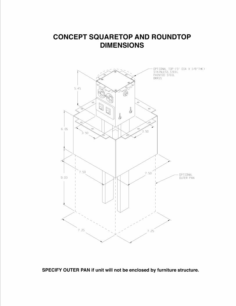
CONCEPT SQUARETOP AND ROUNDTOPDIMENSIONS
SPECIFY OUTER PAN if unit will not be enclosed by furniture structure.