concept of operations (conops) for wireless roadside
TRANSCRIPT

Federal Motor Carrier Safety Administration (FMCSA)
Concept of Operations (ConOps) for Wireless Roadside Inspection
Draft Version
NSTD-07-0104 D.5
August 2008
Prepared by: Prepared for:
11100 Johns Hopkins Road Laurel, MD 20723-6099

ConOps for Wireless Roadside Inspection
Draft Version It is important to note that this is a draft document. This version of the document is complete. The document may contain sections that have not been completely reviewed internally. The material presented herein will undergo several iterations of review and comment before a baseline version is published.
Please note: This document is disseminated in the interest of information exchange. JHU/APL assumes no liability for its contents or use thereof. This report does not constitute a standard, specification, or regulation. JHU/APL does not endorse products or manufacturers.
Please send comments to: Ms. Valerie B. Barnes JHU/APL 96 Laurel Drive Fayetteville, PA 17222 Phone/FAX: 717-352-0131 E-mail: [email protected]
Change Summary: Concept of Operations (ConOps) for Wireless Roadside Inspections Date Type Version
30 January 2007 Initial draft published for review. Draft 2.0 16 November 2007 Updated draft to clarify scope of WRI and incorporate comments.
Did not distribute. Draft 3.0
27 February 2008 Updated draft. Reset scope to include uses of SDMS. Added concepts for “tiers” of the SDMS and incentives. Did not distribute.
Draft 4.0
14 August 2008 Updated to reflect comments received from team and others. Will publish for review.
Draft 5.0
The Johns Hopkins University Applied Physics Laboratory 08/25/08 10:33 AM Draft D.5 Page ii

ConOps for Wireless Roadside Inspection
Concept of Operations (ConOps) for Wireless Roadside Inspection (WRI)
Preface
New technologies and enforcement strategies could increase dramatically the number of times a commercial motor vehicle and its driver are examined, leading to better-targeted enforcement, safer operations, and reduced numbers of truck and bus crashes. The Federal Motor Carrier Safety Administration (FMCSA) Wireless Roadside Inspection Program will demonstrate the feasibility and value of assessing truck and bus drivers and vehicles 100 times more often than is possible using today’s approaches. The program will evaluate the potential benefits to both the motor carrier industry and to government. In addition to the safety benefits noted above, potential benefits to industry include keeping safe and legal drivers and vehicles moving on the highways.
During a “wireless roadside inspection” public sector entities (people and systems) will use real-time data to establish the identities of the commercial motor vehicle, carrier, and driver and to examine the condition of the driver and vehicle. These data will be collected from the vehicle and provided wirelessly either from the vehicle or from the carrier's off-road system. The set of information to be used in the assessment (i.e., inspection) is termed the “Safety Data Message Set” (SDMS). The motor carrier will be responsible for providing the SDMS. Initially, the full SDMS will contain basic identification data (for driver, vehicle, and carrier), the driver’s log, a small set of vehicle measurement data, and selected vehicle status information. The extent of the wireless roadside inspection will depend on whether the full SDMS or a subset is provided.
FMCSA has developed a multi-year roadmap for the Wireless Roadside Inspection Program and has organized the program into three major phases with critical “go/no-go” decision points after each. The three phases are (1) Technical Concept Development and Demonstration, (2) Pilot Testing, and (3) Field Operational Testing. As part of the first phase, the program team collaborated with private-sector onboard equipment and service providers to conduct a proof-of-concept test in August 2007. The program is now entering the Pilot Testing phase. This revised draft technical concept of operations reflects changes resulting from lessons learned during phase 1 initial testing and from stakeholder feedback.
The Johns Hopkins University Applied Physics Laboratory 08/25/08 10:33 AM Draft D.5 Page iii

ConOps for Wireless Roadside Inspection
This Page Intentionally Blank
The Johns Hopkins University Applied Physics Laboratory 08/25/08 10:33 AM Draft D.5 Page iv

ConOps for Wireless Roadside Inspection
Concept of Operations (ConOps) for Wireless Roadside Inspection
Table of Contents
Preface............................................................................................................................................ iii
1. Scope......................................................................................................................................1–1
1.1 Identification ...........................................................................................................1–2
1.2 Document Overview ...............................................................................................1–2
1.3 System Overview....................................................................................................1–2
2. References..............................................................................................................................2–1
3. Current Situation....................................................................................................................3–1
3.1 Background, Objectives, and Scope .......................................................................3–1
3.2 Overview of Existing Policies and Constraints ......................................................3–2
3.3 Description of the Current Situation .......................................................................3–5
3.4 Modes of Operation Today .....................................................................................3–8
3.5 Stakeholders............................................................................................................3–9
4. Motivation for Improvement..................................................................................................4–1
4.1 Justification of Changes..........................................................................................4–2
4.2 Assumptions and Constraints..................................................................................4–5
4.3 Users’ Needs ...........................................................................................................4–7
4.4 Description of Desired Changes .............................................................................4–9
4.5 Priorities among Changes .....................................................................................4–11
4.6 Changes Considered but Not Included .................................................................4–11
5. Concepts for the Proposed Approach ....................................................................................5–1
5.1 Background, Objectives, and Scope .......................................................................5–1
5.2 Key Concepts ..........................................................................................................5–1
5.3 Operational Policies and Constraints ......................................................................5–3
5.4 Description of the Proposed System.......................................................................5–5
5.5 SDMS....................................................................................................................5–15
5.6 Modes of Operation ..............................................................................................5–18
5.7 User Classes ..........................................................................................................5–19
The Johns Hopkins University Applied Physics Laboratory 08/25/08 10:33 AM Draft D.5 Page v
ConOps for Wireless Roadside Inspection
6. Operational Scenarios ............................................................................................................6–1
6.1 Major Operational Scenarios ..................................................................................6–3
6.2 Common Steps ........................................................................................................6–8
6.3 Non-Nominal Scenarios........................................................................................6–15
7. Summary of Impacts ..............................................................................................................7–1
7.1 Operational Impacts ................................................................................................7–1
7.2 Organizational Impacts ...........................................................................................7–4
7.3 Impacts During Development .................................................................................7–4
8. Analysis of the ConOps .........................................................................................................8–1
8.1 Summary of Improvements.....................................................................................8–1
8.2 Disadvantages and Limitations ...............................................................................8–1
8.3 Alternatives and Tradeoffs Considered ..................................................................8–1
9. Acronyms and Abbreviations ................................................................................................9–1
10. Glossary ...............................................................................................................................10–1
Appendix A. CVSA Levels of Inspection...................................................................................A–1
Appendix B. Current System Descriptions.................................................................................B–1
Appendix C. System Qualities....................................................................................................C–1
Appendix D. Potential Data Sources for SDMS.........................................................................D–1
The Johns Hopkins University Applied Physics Laboratory 08/25/08 10:33 AM Draft D.5 Page vi

ConOps for Wireless Roadside Inspection
Table of Figures
Figure 1-1: WRI Concept A: Vehicle-to-Roadside Communications via Transceiver ..............1–3 Figure 1-2: WRI Concept B: Carrier-to Government System Communications via CMRS......1–4 Figure 1-3: WRI Concept C: Enforcement Identifies Vehicle and Requests SDMS .................1–5 Figure 3-1: Current FMCSA Information Systems ....................................................................3–6 Figure 3-2: FMCSA Systems after COMPASS Is Complete .....................................................3–7 Figure 3-3: Typical State Information Systems ..........................................................................3–8 Figure 4-1: Major Uses of WRI’s SDMS Information ...............................................................4–2 Figure 4-2: Estimated Daily Truck Volume, 2002 .....................................................................4–3 Figure 4-3: Forecast of Daily Truck Volume, 2035 ...................................................................4–3 Figure 5-1: Major Conceptual Components of the WRI System................................................5–9 Figure 5-2: Color Codes............................................................................................................5–10 Figure 5-3: WRI System Components Distributed Geographically .........................................5–12 Figure 5-4: Draft Tier 1 SDMS Contents .................................................................................5–15 Figure 6-1: Generic, Simplified Data Flow ................................................................................6–2 Figure 6-2: SDMS Feeding CSA 2010 Operational Model......................................................6–15
The Johns Hopkins University Applied Physics Laboratory 08/25/08 10:33 AM Draft D.5 Page vii

ConOps for Wireless Roadside Inspection
This Page Intentionally Blank
The Johns Hopkins University Applied Physics Laboratory 08/25/08 10:33 AM Draft D.5 Page viii

ConOps for Wireless Roadside Inspection
1. SCOPE
According to the Large Truck Crash Causation Study [Reference 2], 56% of fatal truck crashes are linked to a truck-driver related crash factor.1 Truck numbers and mileage grow each year, but roadside safety inspection resources remain constant. New technologies and enforcement strategies could increase dramatically the number of times a commercial vehicle is examined, leading to better-targeted enforcement, safer operations, and reduced numbers of truck and bus crashes. The Federal Motor Carrier Safety Administration (FMCSA) Wireless Roadside Inspection (WRI) Program will demonstrate the feasibility and value of assessing truck and bus drivers and vehicles 100 times more often than is possible using today’s approaches. The program will evaluate the potential benefits to both the motor carrier industry and to government. In addition to the safety benefits noted above, potential benefits to industry include keeping safe and legal drivers and vehicles moving on the highways.
During a “wireless roadside inspection” public sector entities (people and systems) will use real-time data to establish the identities of the commercial motor vehicle (CMV), carrier, and driver and to examine the condition of the driver and vehicle. These data will be collected from the vehicle and provided wirelessly either from the vehicle or from the carrier's off-road system. The set of information to be used in the assessment (i.e., inspection) is termed the “Safety Data Message Set” (SDMS). The motor carrier will be responsible for providing the SDMS. Initially, the full SDMS will contain basic identification data (for driver, vehicle, and carrier), the driver’s log, a small set of vehicle measurement data, and selected vehicle status information. The extent of the wireless roadside inspection will depend on whether the full SDMS or a subset is provided.
The vision for the WRI Program is that motor carrier safety is improved through dramatic increases in roadside safety inspections due to wireless inspections conducted using proven technologies and processes. Driver and vehicle safety assessments occur frequently enough to ensure compliance while minimizing disruptions to safe and legal motor carrier transportation. This vision is realized through wide industry and public agency participation.
The goal for the WRI Program is improved motor carrier safety (reduction in accidents) due to increased compliance (change in motor carrier and driver behavior) due to a higher frequency of roadside safety inspections using wireless technologies.
FMCSA conducted a study [Reference 3] to develop and analyze various concepts of operations that would link advanced on-board monitoring technologies together with a means of wirelessly communicating such information to local enforcement agencies. The intent was to improve the quality, efficiency, and effectiveness of the North American Standard Inspection program. The study concluded that FMCSA should move forward with research in wireless inspection concepts. This document builds on that study to refine the concept of operations (ConOps) for the WRI Program.
1 Includes both single- and multiple-vehicle fatal truck crashes.
The Johns Hopkins University Applied Physics Laboratory 08/25/08 10:33 AM Draft D.5 Page 1–1

ConOps for Wireless Roadside Inspection
1.1 Identification
This document is titled Concept of Operations for Wireless Roadside Inspection. The outline for the document is based on the Software Engineering Standards Committee of the Institute of Electrical and Electronics Engineers (IEEE) Computer Society standard for a ConOps document [Reference 1]. This is draft 5 of the document. This version is an update to draft 2 [Reference 17], published in early 2007. Other draft versions were not published.
1.2 Document Overview
This document describes the envisioned ConOps for WRIs. The assumed initial operational timeframe is 2014-2016. This document describes the proposed operational environment, characteristics, and processes for examining the safety condition of a commercial motor vehicle and driver using on-board, roadside, and back-office systems.
This ConOps will be used to steer the research and test activities of the WRI Program. The program team and program partners will use the ConOps. The stakeholders involved in the operations described in this ConOps include, but are not limited to, commercial vehicle operators (motor carriers, motor coach operators, drivers, etc.), U.S. Department of Transportation (USDOT), state law enforcement, technology vendors, service providers, vehicle manufacturers, and safety analysts.
Chapter 9 lists abbreviations and acronyms. Chapter 10 defines key terms used in this document.
1.3 System Overview
Figures 1-1, 1-2, and 1-3 illustrate alternative high-level concepts for wireless inspections. In each case, identifiers, driver’s log, and selected vehicle measurements and status are packaged into an SDMS and provided to a government system for use in enforcement, compliance, and assessment activities.
Figure 1-1 shows the vehicle transmitting the SDMS wirelessly to the roadside via a dedicated short-range communications (DSRC) transceiver.
The Johns Hopkins University Applied Physics Laboratory 08/25/08 10:33 AM Draft D.5 Page 1–2

ConOps for Wireless Roadside Inspection
Vehicle-Vehicle-to-Roadside (to-Roadside (ttransceiverransceiver/transponder)/transponder) TThhee sasafefetyty dadatata mmeessssagagee sesett iiss vveerriififieded,, aarrchichivveded,,33 andand sshhaarreedd.. IItt mmaayy bebe uusseded ffoorr rereaall-t-timimee enenffoorcercemmenent,t, cocomplmpliianancece,, aanndd asassseessmessmenntt.. TThhee dadattaa wwiillll alalssoo bbee usedused toto upupddaattee tthhee ccaarrierrierr’’ss aanndd ddrriivver’er’ss ssaafefetyty aasssesessmssmeenntts.s. TThhee ccaarrrrieierr cacann vveeririfyfy tthhee SSDDMMSS infinfoormrmatatioion usn useedd inin tthe uhe uppddaatteess..
BaBaBackckck-Office-Office-Office RoadsideRoadsideRoadsideRoadsideSSSyyystststemememsss
TTThhhe vee vee vehhhiiicccllleee tttrrraaannnsssmmmiiitttsss ttthhheee 222safetysafetysafety dddaaatttaaa mmmeeessassassage sege sege settt wwwiiirererelelelesssssslylyly tototo thththeee rororoaaadddsssiiidedede...CoCoCommermmermmercccialialial
MotorMotorMotor VeVeVehichichicllleee
11 ThThee vevehhiiccllee enenccoountuntererss a roa roadadssiiddee rereadadeerr.. IdIdenentitififiererss,, ddrriviveerr dudutyty ststaattuuss,, anandd seselleecctteedd
vevehhiiccllee memeaassurureses arare pe paacckkaaggeed ind intoto aa ssaaffeettyy data messdata messageage set (Sset (SDDMMSS))..
Figure 1-1: WRI Concept A: Vehicle-to-Roadside Communications via Transceiver
Under concept A, the vehicle will send the SDMS when it encounters a DSRC reader along the road.
Figure 1-2 shows the vehicle routinely sending the information needed for the SDMS to its associated motor carrier/service provider.
The Johns Hopkins University Applied Physics Laboratory 08/25/08 10:33 AM Draft D.5 Page 1–3

ConOps for Wireless Roadside Inspection
Carrier/Service ProvCarrier/Service ProvCarrier/Service Provideriderider to Goto Goto Govvveeernrnrnment Systement Systement Systemmmsss (Comm(Comm(Commeeercial Mrcial Mrcial Mobile Robile Robile Raaadio Service)dio Service)dio Service)
ThThTheee sasasafffeeety dty dty daaatttaaa mmmeeessssssageageage ssseeet it it isss vvveeerrriiifiefiefieddd,,, aaarrrccchhhiiivvveeeddd,,,555 anananddd ssshhhaaarrreeeddd... ItItIt mmmaaayyy bbbeee uuussseeeddd aaattt ttthe roadshe roadshe roadsiiide fde fde fooorrr rrrealealeal-ti-ti-timmmeee enenenfffooorrrcccemememenenent,t,t, comcomcomppplialialiannnccceee,,, aaannnddd aaassssesesessssssmememennnttt. T. T. Thhheee dddaaatttaaa wwwill alill alill alsososo bbbeee useuseuseddd tototo uuupppdddaaatetete ttthhheee cccaaarrrrrrierierier’’’sss and dand dand drrriveriveriver’’’sss sssaaafffeeetttyyy assassasseeessmessmessmennntttsss. T. T. Thhheee cacacarrrrrrieieierrr cacacannn vvveeerifyrifyrify thththe SDe SDe SDMMMSSS iiinnnforforformmmaaatttioioionnn uuusssededed ininin ttthhheee uuupdatespdatespdates...
GoGoGovvveeerrrnnnmememennnttt BBBaaaccckkk-O-O-Offffffiiiccceee RoaRoaRoaRoaddddsidesidesidesideSySySystststemememsss
TheTheThe SDMS iSDMS iSDMS isss ssseeentntnt tototo aaa gggooovevevernrnrnment bacment bacment back-k-k-oooffffffiiiccceee sssyyystststeeemmm...
444
222Carrier/SeCarrier/SeCarrier/Serrrvvviiicecece PPPrrrooovvviiidddererer BaBaBackckck--- ComComComCommmmmercialercialercialercial
TTThehehe vevevehihihicccllle ee ee ennncococounununttteeerrrsss aaa tttrrriiiggggggeeerrr (((eee.g.g.g...,,, aaa gegegeofofofeeennnccceee bbbooouuunnndadadarrryyy))) tttooo ssseeendndnd ttthhhe Se Se SDDDMMMSSS... TTThe cahe cahe carrrrrriiieeerrr ororor ssseeervirvirviccceee
222
IIIfff nnneeecccesesessssaaarrryyy, n, n, neeewww dadadatatata aaarrreee Office SyOffice SyOffice Systststeeemmmsss VeVeVeVehiclehiclehiclehicle prprprovovovidididererer iiisss nnnoootttifiifiifieeeddd... cccooolllllleeeccctttededed fffrrrooommm ttthhhe vee vee vehhhiiicccllle.e.e. The SDMS isThe SDMS isThe SDMS is aaasssssseeemmmbbbllleeeddd... 333
ThThTheee vevevehihihicccllleee tttrrransansansmitmitmitsss vavavariririooouuus ds ds daaatatata eeellleeemmmeeennntttsss,,, 111 iiinnncccllluuudddiiinnnggg thothothossse ie ie innn the sathe sathe safetfetfetyyy dddaaatatata messmessmessageageage
ssseeettt (((SSSDMS),DMS),DMS), wwwiiirrreeelesleslesssslllyyy tototo thethethe serserservvviciciceee proproprovvvidididererer ooorrr mmmoootototor cr cr caaarrrrrriiieeerrr...
Figure 1-2: WRI Concept B: Carrier-to Government System Communications via CMRS
Under concept B, when the vehicle encounters a trigger (for example, a geofence boundary), the vehicle will request that the carrier/service provider package and send the SDMS. If necessary to meet the SDMS timeliness requirements, the carrier/service provider may retrieve fresh data from the vehicle. Then the carrier or service provider will package and send the SDMS to the government back-office system. Roadside staff and systems may use the SDMS for enforcement, compliance, and assessment.
Figure 1-3 shows the SDMS being provided in response to a request from law enforcement.
The Johns Hopkins University Applied Physics Laboratory 08/25/08 10:33 AM Draft D.5 Page 1–4

ConOps for Wireless Roadside Inspection
Enforcement IEnforcement Identifies Vdentifies Vehicle and Rehicle and Reequests SDMSquests SDMS 22 ViVia aa a bacback-k-ooffffiicece ssyysstteemm,, tthhe vehe vehiiccllee IIDD iiss lliinnkkeded toto ththee
ccaarrrriieerr//seservirvicce pe prroovviidder aer anndd tthhee SDMSSDMS isis rrequeequestedsted..
55 TThe sahe saffeettyy datdataa mmeessssaagege sseet it iss veverriiffiied,ed, arcarchhiivveedd,, aanndd sshhaarred. Ited. It isis proviproviddeedd ttoo tthhee rreeqquuesesttiingng ooffffiicer/scer/syysstteemm ffoorr popotetentntiiaal usl use ie inn reareall--ttiimmee eennfoforcemrcemeennt,t, comcompplilianance, ace, and and asssseessmssmentent.. TThhee dadatata wwill alsoill also bbee uusseded toto uuppddaattee tthhee cacarrierrierr’s’s aanndd drivdriver’s saer’s safefetyty asseassessmssmenents. Tts. Thhee carcarrriieerr cacan vn veeririfyfy ththee SDSDMMSS iinnforformmaattiioonn uusseded iinn ththee upupdadatetess..
GGoovveerrnnmementnt BackBack--OOfffficeice
SySyststememss RoadsideRoadsideRoadside 11 EnfoEnforrccememenent it iddeennttiiffiesies ththe ve veehhiiclclee (e(e.g.g..,, vviiaa LLPPRR)) aand rnd reequesqueststs ththe SDMSe SDMS..
44 The SDMThe SDMSS iiss sseentnt toto aa
govgoveerrnmnmeenntt baback-ock-offifficcee sysystemstem.. 22CaCarrrriierer/S/Serervviiccee ProvProviidder Ber Baack-ck- ComComCommmmererercialcialcial
IIff nneecceessssaarryy,, nenew dw daattaa araree OOffffiiccee SySyststememss VeVeVehiclehiclehicle ccoolllleecctteded frofromm ththe ve veehhiiccllee.. TThe SDMhe SDMSS isis assasseembmblleed.d. 33
Figure 1-3: WRI Concept C: Enforcement Identifies Vehicle and Requests SDMS
Under Concept C, enforcement detects and identifies the vehicle, looks up the ID to determine the associated carrier/service provider, and sends a request for the SDMS to that carrier/service provider. If necessary to meet SDMS timeliness requirements, the carrier/service provider may retrieve fresh data from the vehicle. Then the carrier or service provider will package and send the SDMS to the government back-office system, which forwards it to the requesting enforcement officer/system. Roadside staff and systems may use the SDMS for enforcement, compliance, and assessment.
Communications paths and triggers other than those represented in Figures 1-1 through 1-3 may also be feasible and will be considered.
In all cases, the carrier provides the SDMS to a government system. The government system verifies the SDMS automatically to the extent possible. The government system evaluates the information in the SDMS to assess compliance and safety status. If the SDMS indicates there may be a safety problem, the carrier and driver will be informed. The carrier and driver can use the SDMS to identify and address safety problems. Enforcement may also select the vehicle for further examination. Enforcement systems and staff will use the SDMS to support electronic screening and inspections at staffed roadside sites. FMCSA will use the SDMS to update the safety assessment of the carrier and driver. Analysts may use the SDMS in routine or special safety studies. After the identifying information is removed, transportation planners and managers may use the SDMS to gain a better understanding of commercial vehicle operations in their jurisdictions.
The Johns Hopkins University Applied Physics Laboratory 08/25/08 10:33 AM Draft D.5 Page 1–5

ConOps for Wireless Roadside Inspection
This Page Intentionally Blank
The Johns Hopkins University Applied Physics Laboratory 08/25/08 10:33 AM Draft D.5 Page 1–6

ConOps for Wireless Roadside Inspection
2. REFERENCES
1. Software Engineering Standards Committee of the Institute of Electrical and Electronics Engineers (IEEE) Computer Society, IEEE Guide for Information Technology – System Definition – Concept of Operations (ConOps) Document, IEEE Std 1362-1998, approved March 1998.
2. Federal Motor Carrier Safety Administration, The Large Truck Crash Causation Study, 2006. Available online at http://ai.volpe.dot.gov/ltccs.
3. Booz Allen Hamilton for FMCSA, Development and Evaluation of Alternative Concepts for Wireless Roadside Truck and Bus Safety Inspections, Final Project Report, July 2007. Available online at http://www.fmcsa.dot.gov/facts-research/research-technology/report/wireless-inspection-report.pdf.
4. Federal Motor Carrier Safety Administration, The CSA 2010 Dispatch Frequently Asked Questions, Fact Sheet, May 2008. Available online at http://www.fmcsa.dot.gov/safety-security/csa2010/home.htm.
5. John A. Volpe National Transportation Systems Center, Office of Systems and Economic Assessment, Motor Carrier Safety Assessment Division, FMCSA Safety Program Effectiveness Measurement: Intervention Model; Roadside Inspection and Traffic Enforcement Effectiveness Annual Report; Results for 2001, 2002, and 2003, Publication FMCSA-RI-04-029, December 2004. Available online at http://ai.fmcsa.dot.gov/CarrierResearchResults/PDFs/Intervention_Model_v3.pdf
6. Federal Highway Administration, Office of Freight Management and Operations, Freight Facts and Figures 2005; Table 3-5. Commercial Vehicle Weight Enforcement Activities, Publication FHWA-HOP-05-071, November 2005. Available online at http://ops.fhwa.dot.gov/freight/freight_analysis/nat_freight_stats/docs/05factsfigures/index.h tm.
7. Federal Motor Carrier Safety Administration, Request for Information on New Commercial Vehicle Safety Inspection Concepts [Docket No. FMCSA-2005-22097], published in the Federal Register, Vol. 70, No. 157, 16 August 2005, page 48229.
8. 49 Code of Federal Regulations (CFR), subtitle B, chapter III, subchapter B – Federal Motor Carrier Safety Regulations. Available online at http://ecfr.gpoaccess.gov/cgi/t/text/text-idx?sid=2c47c10a750be94b039dabfacdce10fd&c=ecfr&tpl=/ecfrbrowse/Title49/49cfrv5_02 .tpl#300.
9. 49 CFR, subtitle B, chapter I, subchapter C – Hazardous Materials Regulations. Available online at http://ecfr.gpoaccess.gov/cgi/t/text/text-idx?sid=2c47c10a750be94b039dabfacdce10fd&c=ecfr&tpl=/ecfrbrowse/Title49/49cfrv2_02 .tpl.
The Johns Hopkins University Applied Physics Laboratory 08/25/08 10:33 AM Draft D.5 Page 2–1

ConOps for Wireless Roadside Inspection
10. United States Census Bureau, Vehicle Inventory and Use Survey 2002, U.S. Department of Commerce, 2004. Available online at http://www.census.gov/svsd/www/vius/2002.html.
11. US Department of Transportation, Chief Information Officer, Departmental Information Resource Management Manual (DIRMM), Chapter 10-Information Assurance. Available online at http://cio.ost.dot.gov/portal/site/cio/dirmm/index.html.
12. US Department of Transportation, Research and Innovative Technology Administration, Intelligent Transportation Systems, Vehicle Infrastructure Integration Overview. Available online at http://www.its.dot.gov/vii/vii_overview.htm.
13. FMCSA DataQs, https://dataqs.fmcsa.dot.gov.
14. Federal Motor Carrier Safety Administration, 49 CFR Parts 385 and 395 Hours of Service of Drivers: Interim Final Rule, [Docket No. FMCSA–2004–19608], RIN–2126–AB14, published in the Federal Register, Vol. 72, No. 241, 17 December 2007, page 71247.
15. Federal Motor Carrier Safety Administration, 49 CFR Part 350, et al. Electronic On-Board Recorders for Hours-of-Service Compliance: Proposed Rule, [Docket No. FMCSA–2004– 18940], RIN–2126–AA89, published in the Federal Register, Vol. 72, No. 11, 18 January 2007, page 2340.
16. Department of Transportation, Office of the Secretary of Transportation, Report on DOT Significant Rulemakings, July 2008, http://regs.dot.gov/rulemakings/index.htm.
17. Johns Hopkins University/Applied Physics Laboratory for FMCSA, Concept of Operations for Wireless Roadside Inspections, NSTD-07-0104 D.2, January 2007; published via NSTD-L-21827.
18. Commercial Vehicle Safety Alliance (CVSA), North American Standard Inspection Levels (Web site), http://www.cvsa.org/programs/nas_levels.aspx.
19. FMCSA Analysis and Information (A&I), A&I On-Line Help: Roadside Inspections, http://ai.fmcsa.dot.gov/Help/Help.asp#ri1.
20. Federal Highway Administration, Freight Facts and Figures 2007, Chapter III, The Freight Transportation System. Available online at http://ops.fhwa.dot.gov/freight/freight_analysis/nat_freight_stats/docs/07factsfigures/.
21. United States Code, “Prohibition on release and use of certain personal information from State motor vehicle records”, Title 18, Part 1, Chapter 123, §2721, 2 January 2006. [Also known as the Drivers Privacy Protection Act]. Available online at http://uscode.house.gov/.
22. United States Code, “Public information; agency rules, opinions, orders, records, and proceedings”, 5 U.S.C. § 552, amended 2002. [Also known as the Freedom of Information Act]. Available online at http://www.usdoj.gov/oip/foiastat.htm.
The Johns Hopkins University Applied Physics Laboratory 08/25/08 10:33 AM Draft D.5 Page 2–2

ConOps for Wireless Roadside Inspection
23. International Organization for Standardization (ISO) 9000, Quality Management Systems – Fundamentals and Vocabulary, third edition, 15 September 2005. Available online at http://www.iso.org.
24. ISO/International Electrotechnical Commission (IEC) 9126-1:2001 (E), Software Engineering – Product Quality, Part 1: Quality Model, first edition, 15 June 2001. Available online at http://www.iso.org.
25. ISO/IEC 15288:2008(E) IEEE Std 15288-2008, Systems and Software Engineering – System Life Cycle Processes, second edition, 1 February 2008. Available online at http://www.iso.org.
26. ISO/IEC 26702_2007(E) IEEE Std 1220-2005, Systems Engineering – Application and Management of the Systems Engineering Process, first edition, 15 July 2007. Available online at http://www.iso.org.
27. Barbacci, Mario, Thomas H. Longstaff, Mark H. Klein, and Charles B. Weinstock, Carnegie Mellon University Software Engineering Institute, Quality Attributes, Technical Reports: CMU/SEI-95-TR-021, ESC-TR-95-021, December 1995. Available online at http://www.sei.cmu.edu/publications/documents/95.reports/95.tr.021.html.
28. O’Brien, Liam, Len Bass, and Paulo Merson, Carnegie Mellon University Software Engineering Institute, Quality Attributes and Service-Oriented Architectures, CMU/SEI-2005-TN-014, September 2005. Available online at http://www.sei.cmu.edu/publications/documents/05.reports/05tn014.html.
The Johns Hopkins University Applied Physics Laboratory 08/25/08 10:33 AM Draft D.5 Page 2–3

ConOps for Wireless Roadside Inspection
This Page Intentionally Blank
The Johns Hopkins University Applied Physics Laboratory 08/25/08 10:33 AM Draft D.5 Page 2–4

ConOps for Wireless Roadside Inspection
3. CURRENT SITUATION
FMCSA, in cooperation with its partners and customers, strives to reduce crashes, injuries, and fatalities involving large trucks and buses. A key element of FMCSA’s safety strategy is the roadside safety inspection program. Truck numbers and mileage grow each year, but roadside safety inspection resources remain constant. The wireless inspection approach is intended to increase the number of inspections and improve safety performance.
3.1 Background, Objectives, and Scope
For a commercial vehicle today, the likelihood of being inspected is far less than being weighed. When inspections do occur, it is very likely that a violation will be found. According to FMCSA’s statistics for 2003 [Reference 5], more than 3 million roadside inspections were conducted, with a violation rate of 73%. This can be contrasted with the number of weight measurements taken (more than 177 million, including both static scales and weigh-in-motion) and violations detected (less than 1%) [Reference 6].
Today a vehicle is selected for inspection based on resource availability (e.g., whether an inspector is available, parking area at inspection site, traffic flow, etc.), safety history (safety fitness rating, date of last inspection), and other screening criteria (e.g., weight, visual observation of a potential problem). According to the Large Truck Crash Causation Study [Reference 2], 56% of fatal truck crashes are linked to a truck-driver-related crash factor (includes both single- and multiple-vehicle fatal truck crashes). In today’s inspection selection process, it is usually not possible to identify the driver. The WRI process will enable automated driver, carrier, and vehicle identification so that enforcement resources can be focused better.
As stated in FMCSA’s request for information on new commercial vehicle safety inspection concepts [Reference 7],
“Commercial vehicle roadside safety inspections represent one of the most effective tools for monitoring and regulating the condition of the in-use commercial vehicle fleet, as well as for auditing and enforcing driver and operational-related safety practices, including hours of service, proper driver credentialing, and other safety aspects of commercial vehicle equipment and operations. New technologies such as advanced sensor and on-board diagnostics as well as wireless communications offer the potential for dramatically improving the effectiveness and efficiency of the roadside commercial vehicle safety inspection process.”
The objective for changing the operational concept is to increase dramatically the likelihood of a commercial vehicle being inspected and to realize significant improvements in commercial vehicle safety. The scope of this ConOps is focused on wireless inspections.
The Johns Hopkins University Applied Physics Laboratory 08/25/08 10:33 AM Draft D.5 Page 3–1

ConOps for Wireless Roadside Inspection
3.2 Overview of Existing Policies and Constraints
Commercial vehicles may be inspected either at inspection sites or when mobile enforcement officers stop them. The number of roadside inspections is constrained by the availability of staff to conduct them, availability of facilities, traffic volume, and safety considerations (e.g., safety of the inspector, safety of the traveling public, etc.).
3.2.1 Existing Roadside Inspection Program
FMCSA’s A&I (Analysis & Information) Web site [Reference 19] describes the existing roadside inspection program:
“The roadside inspection program consists of roadside inspections performed by qualified safety inspectors following the guidelines of the North American Standard, which was developed by the Commercial Vehicle Safety Alliance in cooperation with the FMCSA. Most roadside inspections by the states are conducted under the Motor Carrier Safety Assistance Program (MCSAP), a grant program administered by the FMCSA…
A roadside inspection occurs when a MCSAP inspector conducts an examination on individual commercial motor vehicles and drivers to determine if they are in compliance with the Federal Motor Carrier Safety Regulations (FMCSRs) and/or Hazardous Materials Regulations (HMRs.) Serious violations result in the issuance of driver or vehicle out-of-service (OOS) orders. These violations must be corrected before the affected driver or vehicle can return to service. Moving violations also may be recorded in conjunction with a roadside inspection.”
The levels for North American Standard (NAS) driver/vehicle inspections are [Reference 18]:
• “LEVEL I. North American Standard Inspection - An inspection that includes examination of driver’s license; medical examiner’s certificate and Skill Performance Evaluation (SPE) Certificate (if applicable); alcohol and drugs; driver’s record of duty status as required; hours of service; seat belt; vehicle inspection report (if applicable); brake systems; coupling devices; exhaust systems; frame; fuel systems; lighting devices (turn signals, brake lamps, tail lamps, head lamps and lamps/flags on projecting loads); safe loading; steering mechanism; suspension; tires; van and open-top trailer bodies; wheels and rims; windshield wipers; emergency exits for buses; HM requirements as applicable. HM required inspection items will be inspected by certified HM inspectors.
• LEVEL II. Walk-Around Driver/Vehicle Inspection - An examination that includes each of the items specified under the North American Standard Inspection. As a minimum, Level II inspections must include examination of: driver’s license; medical examiner’s certificate and Skill Performance Evaluation (SPE) Certificate (if applicable); alcohol and drugs; driver’s record of duty status as required; hours of service; seat belt; vehicle inspection report (if applicable); brake systems; coupling devices; exhaust systems; frame; fuel systems; lighting devices (turn signals, brake lamps, tail lamps, head lamps and lamps/flags on projecting loads); safe loading; steering mechanism;
The Johns Hopkins University Applied Physics Laboratory 08/25/08 10:33 AM Draft D.5 Page 3–2

ConOps for Wireless Roadside Inspection
suspension; tires; van and open-top trailer bodies; wheels and rims; windshield wipers; emergency exits on buses, and HM requirements as applicable. HM required inspection items will be inspected by certified HM inspectors. It is contemplated that the walk-around driver/vehicle inspection will include only those items, which can be inspected without physically getting under the vehicle.
• LEVEL III. Driver/Credential Inspection - An examination that includes those items specified under the North American Standard Level III Driver/Credential Inspection Procedure. As a minimum, Level III inspections must include, where required and/or applicable, examination of the driver’s license; medical examiner’s certificate and Skill Performance Evaluation (SPE) Certificate; driver’s record of duty status; hours of service; seat belt; vehicle inspection report; and HM requirements. Those items not indicated in the North American Standard Level III Driver/Credential Inspection Procedure shall not be included on a Level III inspection.
• LEVEL IV. Special Inspections - Inspections under this heading typically include a one-time examination of a particular item. These examinations are normally made in support of a study or to verify or refute a suspected trend.
• LEVEL V. Vehicle-Only Inspection - An inspection that includes each of the vehicle inspection items specified under the North American Standard Inspection (Level I), without a driver present, conducted at any location.
• LEVEL VI. North American Standard Inspection for Transuranic Waste and Highway Route Controlled Quantities (HRCQ) of Radioactive Material - An inspection for select radiological shipments, which include inspection procedures, enhancements to the North American Standard Level I Inspection, radiological requirements, and the North American Standard Out-of-Service Criteria for Transuranic Waste and Highway Route Controlled Quantities (HRCQ) of Radioactive Material.
As of January 1, 2005, all vehicles and carriers transporting highway route controlled quantities (HRCQ) of radioactive material are regulated by the U.S. Department of Transportation and required to pass the North American Standard Level VI Inspection.
Previously, U.S. Department of Energy (DOE) voluntarily complied with the North American Standard Level VI Inspection Program requirements.
Select radiological shipments include highway route controlled quantities (HRCQ) of radioactive material as defined by Title 49 CFR Section 173.403. And, because only a small fraction of transuranics are HRCQ, DOE has decided to include its transuranic waste shipments in the North American Standard Level VI Inspection Program.
• LEVEL VII. Jurisdictional Mandated Commercial Vehicle Inspection - An inspection that is a jurisdictional mandated inspection program that does not meet the requirements of any other level of inspection. An example will include inspection programs such as, but not limited to: school buses; limousines; taxis; shared ride; hotel courtesy shuttles, and other intrastate/intraprovincial operations. These inspections may be conducted by CVSA-certified inspectors, other designated government employees or
The Johns Hopkins University Applied Physics Laboratory 08/25/08 10:33 AM Draft D.5 Page 3–3

ConOps for Wireless Roadside Inspection
jurisdiction approved contractors. Inspector training requirements shall be determined by each jurisdiction. No CVSA decal shall be issued for a Level VII inspection but a jurisdiction-specific decal may be applied.”
Appendix A shows the main elements inspected in Levels I-V.
3.2.2 Existing Federal Regulations
Existing FMCSRs [Reference 8] associated with roadside inspections include:
• 374 Passenger Carrier Regulations
• 382 Controlled Substances and Alcohol Use and Testing
• 383 Commercial Driver’s License Standards; Requirements and Penalties
• 385 Safety Fitness Procedures
• 386 Rules of Practice for Motor Carrier, Broker, Freight Forwarder, and Hazardous Materials Proceedings
• 387 Minimum Levels of Financial Responsibility for Motor Carriers
• 390 General
• 391 Qualifications of Drivers and Longer Combination Vehicle (LCV) Driver Instructors
• 392 Driving of Motor Vehicles
• 393 Parts and Accessories Necessary for Safe Operation
• 395 Hours of Service of Drivers
• 396 Inspection, Repair, and Maintenance
• 397 Transportation of Hazardous Materials; Driving and Parking Rules
• 398 Transportation of Migrant Workers
• 565 Vehicle Identification Number Requirements
• 571 Federal Motor Vehicle Safety Standards
• 658 Truck Size and Weight, Route Designations – Length, Width, and Weight Limitations
• Appendix G Minimum Periodic Inspection Standards
Existing HMRs [Reference 9] associated with roadside inspections include:
• 171 General Information, Regulations, and Definitions
• 172 Hazardous Materials Table, Special Provisions, Hazardous Materials Communications, Emergency Response Information, and Training Requirements
• 173 Shippers General Requirements for Shipments and Packagings
The Johns Hopkins University Applied Physics Laboratory 08/25/08 10:33 AM Draft D.5 Page 3–4

ConOps for Wireless Roadside Inspection
• 177 Carriage By Public Highway
3.3 Description of the Current Situation
This section characterizes today’s roadside processes and the information systems that support those activities.
3.3.1 Traditional Roadside Processes
Currently, most inspections are conducted “manually” by a qualified inspector. Traditionally, qualified inspectors conduct inspections at fixed or temporary sites using permanently installed and/or portable equipment. Capabilities at inspection sites vary.
As a commercial vehicle approaches a staffed fixed or temporary weigh station, it may be “screened” to determine whether to pull it in for further examination. Today screening is typically accomplished using various technologies to assess the weight and size of the vehicle. Some sites also identify the vehicle and carrier electronically using 900 MHz RF (radio frequency) communications, physically using optical character recognition, or manually (a person reads the license plate and/or USDOT number). In some jurisdictions, once the vehicle and carrier are identified, law enforcement personnel can access infrastructure data to factor in the safety record of the associated carrier, registration status of the vehicle, etc., to determine whether to pull in the vehicle for a traditional inspection.
Increasingly, mobile enforcement vehicles are outfitted with equipment to exchange data and query infrastructure systems and to conduct some level of safety inspection. Today, the enforcement officer usually relies on visual information to identify the carrier (USDOT number on the side of the vehicle) and vehicle (license plate). The identifiers can be used to query for additional information. If the vehicle is stopped, temporary equipment can be deployed to weigh the vehicle and conduct an inspection.
Today, most jurisdictions have limited automated capabilities to support safety enforcement, compliance, and assessment activities. The most widespread automatic functionality involves weighing and measuring the vehicle. At some sites, additional sensors measure radiological, chemical, or nuclear signatures. At some sites, screening is automated with devices that identify the carrier and vehicle and then make a pull-in or bypass recommendation.
Per federal regulations, drivers are required to keep track of their hours of service (HOS). Inspectors review HOS data during a Level 1 inspection. 49 CFR (Code of Federal Regulations) 395.15 allows the use of an automatic on-board recorder to track driver HOS. If used, the
The Johns Hopkins University Applied Physics Laboratory 08/25/08 10:33 AM Draft D.5 Page 3–5

ConOps for Wireless Roadside Inspection
automatic recorder must “produce, upon demand, a driver’s hours of service chart, electronic display, or printout showing the time and sequence of duty status changes” [Reference 8, 49 CFR 395.15].
FMCSA currently does not have specific regulatory authority to use any vehicle status data retrieved electronically in the inspection process.
3.3.2 Information Systems that Support Enforcement, Compliance, and Assessment
Federal and state information systems support the enforcement, compliance, and assessment processes. The systems collect, share, and analyze inspection and related information. The WRI approach will build on several of these existing systems.
3.3.2.1 Federal Systems
Figure 3-1 illustrates current FMCSA information systems. Appendix B.1 provides a brief description of each current system involved with inspections or inspection data.
MCMIS
HMPIP Central
HMPIP Local
SAFETYNET
SAFER/ PRISM
Query Central PIQ
ASPEN
ISS CDLIS Access
Kofax
ProVu
CaseRite UFA
CAPRI EMISA&I
EDMS
L&I
FARS Pay.gov
State Systems
CDLIS SCT
CDLIS
Laptop Office
Central / Web External Gray text: Not directly involved with inspections or inspection data
Figure 3-1: Current FMCSA Information Systems
Today inspectors normally use ASPEN, PIQ, ISS, and CDLIS Access to support a Level 1 inspection. ASPEN records the inspection data. The inspector usually uploads the inspection
The Johns Hopkins University Applied Physics Laboratory 08/25/08 10:33 AM Draft D.5 Page 3–6

FARS
Pay.gov
StateSystems
CDLISSCT
CDLIS
Laptop Central / Web External
FMCSA Portal
Analysis
Enforcement
Registration
Audit
Review
Inspection
Mobile Client
ConOps for Wireless Roadside Inspection
report to SAFETYNET and the SAFER/PRISM central site. MCMIS is the long-term repository for inspection reports.
Under FMCSA’s Information Technology modernization and business process improvement program (COMPASS – Creating Opportunities, Methods, and Processes to Secure Safety), the agency is migrating to a Web-based service-oriented architecture. After COMPASS has been fully deployed, users will access services via the FMCSA Portal as shown in Figure 3-2.
Gray text: Not directly involved with inspections or inspection data
BusinessProcesses
FARS
Pay.gov
State Systems
CDLIS SCT
CDLIS
Laptop Central / Web External
Gray text: Not directly involved with inspections or inspection data
FMCSA Portal
Analysis
Enforcement
Registration
Audit
Review
Inspection
Business Processes
Mobile Client
Figure 3-2: FMCSA Systems after COMPASS Is Complete
After COMPASS has been deployed, inspectors will use the Mobile Client to conduct an inspection. The inspector will upload the inspection report via the FMCSA Portal.
3.3.2.2 State Systems
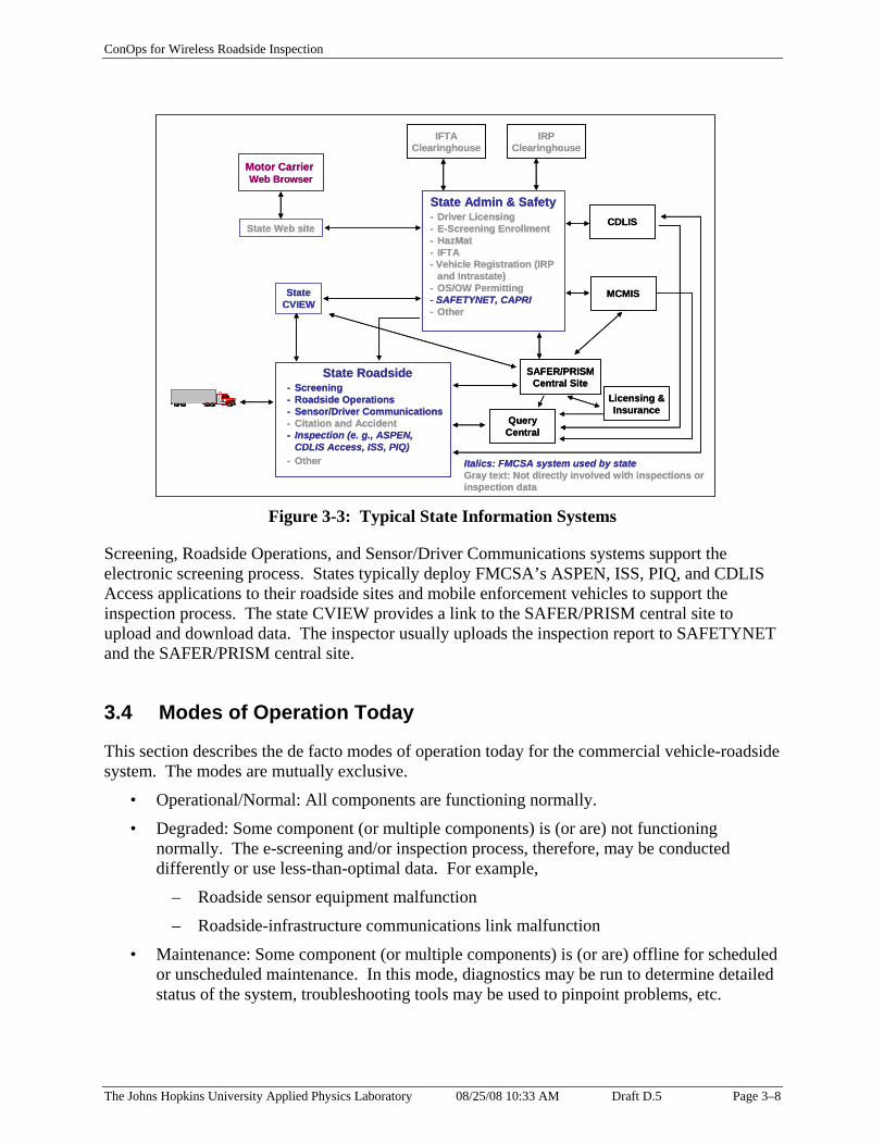
Figure 3-3 illustrates the information systems typically deployed by a state to support commercial motor vehicle activities. Appendix B.2 provides a brief description of typical state systems involved with inspections or inspection data. Not all systems shown in the State Roadside box are deployed at all weigh and inspection sites. States choose to deploy systems based on a number of factors including, but not limited to: state policies and practices; traffic flow, traffic volume, and number of lanes; available site space; existing proprietary solutions; vintage of roadside and communications equipment; and the resources available.
The Johns Hopkins University Applied Physics Laboratory 08/25/08 10:33 AM Draft D.5 Page 3–7
IRIRPP CClleeaarriinghnghouseouse
IFTIFTAA ClCleaearirinngghohouussee
CDCDLILISS
MCMISMCMIS
SSttateate RRooadadsidsidee -- SScrcreeeenininngg -- RRoadsidoadside Opee Operratationsions -- SSeensornsor/D/Drriivveerr CoCommmmuunnicationicationss -- CCitatioitation andn and AAccidccideenntt -- IInspnspectionection (e. g., A(e. g., ASSPENPEN,,
CDLCDLIISS AccAccessess,, IISSSS,, PPIIQQ)) - O- Otthheerr
SSttateate AAddminmin && SSaafetfetyy -- DDrriivveer Lr Liicencensinsingg -- EE-Sc-Scrreeeening Enrning Enroollmentllment -- HazMHazMaatt - I- IFFTTAA -- VVehiclehiclee RReegigistratstratiion (on (IIRPRP
and Intand Intrrastatastate)e) -- OOS/OWS/OW PerPermmittingitting -- SSAAFFEETYTYNENET,T, CCAAPRPRII -- OtOthheerr
SASAFERFER//PRPRISISMM CeCennttrraall SSiittee
MMootor Ctor Caarrierrrier WWeebb BrBroowwseserr
SSttateate CVCVIIEEWW
LLiicensingcensing && InsurInsuraancncee
StState Wate Weeb sitb sitee
QuQueerryy CenCentraltral
ItItalicalics: FMs: FMCSCSA syA syststeemm uused bysed by ststatatee GrGrayay texttext: No: Not dirt direectlyctly iinnvvoollvved wed wiith inth inspespeccttiions orons or ininspectiospection datan data
ConOps for Wireless Roadside Inspection
Figure 3-3: Typical State Information Systems
Screening, Roadside Operations, and Sensor/Driver Communications systems support the electronic screening process. States typically deploy FMCSA’s ASPEN, ISS, PIQ, and CDLIS Access applications to their roadside sites and mobile enforcement vehicles to support the inspection process. The state CVIEW provides a link to the SAFER/PRISM central site to upload and download data. The inspector usually uploads the inspection report to SAFETYNET and the SAFER/PRISM central site.
3.4 Modes of Operation Today
This section describes the de facto modes of operation today for the commercial vehicle-roadside system. The modes are mutually exclusive.
• Operational/Normal: All components are functioning normally.
• Degraded: Some component (or multiple components) is (or are) not functioning normally. The e-screening and/or inspection process, therefore, may be conducted differently or use less-than-optimal data. For example,
– Roadside sensor equipment malfunction
– Roadside-infrastructure communications link malfunction
• Maintenance: Some component (or multiple components) is (or are) offline for scheduled or unscheduled maintenance. In this mode, diagnostics may be run to determine detailed status of the system, troubleshooting tools may be used to pinpoint problems, etc.
The Johns Hopkins University Applied Physics Laboratory 08/25/08 10:33 AM Draft D.5 Page 3–8

ConOps for Wireless Roadside Inspection
• Training: The system is used to train operators. Artificial conditions may be created, and data collected are not entered into the operational databases.
• Idle/Off-line: Some component (or multiple components) is (or are) idle or off-line. No data collection or subsequent processing occurs.
3.5 Stakeholders
The stakeholders involved in current commercial vehicle-roadside activities include:
• Motor carrier and motor coach companies (in this document, the term “motor carrier” refers to both)
Some motor carriers with unsatisfactory safety ratings enter into negotiated settlement agreements with FMCSA and commit to taking specific actions to achieve full compliance with federal regulations; in this document, the term “settlement carriers” refers to them.
• Drivers of commercial vehicles
• Federal Government – U.S. Department of Transportation Federal Motor Carrier Safety Administration (FMCSA)
• State and local law enforcement and their contractors
• Commercial vehicle manufacturers
• Technology vendors
• Service providers
At selected sites, other kinds of “inspection” activities may also occur. For instance, at an international border site, U.S. Customs and Border Protection may examine a driver’s credentials and/or a vehicle’s cargo. The U.S. Department of Agriculture inspects plant and animal shipments. Those activities are not part of this ConOps. However, information collected or used in the safety inspections described herein may also be used by other agencies and vice versa.
The Johns Hopkins University Applied Physics Laboratory 08/25/08 10:33 AM Draft D.5 Page 3–9

ConOps for Wireless Roadside Inspection
This Page Intentionally Blank
The Johns Hopkins University Applied Physics Laboratory 08/25/08 10:33 AM Draft D.5 Page 3–10
ConOps for Wireless Roadside Inspection
4. MOTIVATION FOR IMPROVEMENT
To determine an approach for improving commercial motor vehicle safety, vulnerabilities and gaps in the current operations were analyzed. The Large Truck Crash Causation Study (LTCCS) [Reference 2] identified links between behaviors and crashes. The project report for the Development and Evaluation of Alternative Concepts for Wireless Roadside Truck and Bus Safety Inspections [Reference 3] looked at the LTCCS and analyzed trends in commercial vehicle operations.
These precepts drive the improvements recommended in this ConOps:
• Safer operations are more cost-effective.
• Safer operations benefit society at large.
• Conducting inspections of commercial vehicles contributes to safer operations.
• Because inspection events are rare today, a single “bad” event can skew the safety rating for a carrier.
• Many of today’s trucks are equipped with sensors that monitor system performance characteristics in real time.
• Many of today’s trucks are equipped with on-board recorders that help drivers comply with the hours-of-service (HOS) regulations.
• Technology exists to retrieve on-board sensor data and driver’s logs at the roadside or to transmit the data to a remote location.
• Resources are limited for traditional safety inspections.
• Using technology it is possible, without additional inspection staff, to assess truck/bus drivers and vehicles 100 times more often than is routinely done today.
Figure 4-1 shows how FMCSA expects the SDMS collected during a WRI to be used to improve safety.
The Johns Hopkins University Applied Physics Laboratory 08/25/08 10:33 AM Draft D.5 Page 4–1

Wireless Roadside Inspection
Safety Data Message Set
Wireless Roadside Inspection
Safety Data Message Set
ConOps for Wireless Roadside Inspection
Motor Carrier orService Provider
• Address safety issues• Verify SDMS information
Federal/State CMVSafety Data Systems
• Update carrier safety assessment(CSA 2010 CSM)• Update driver safety assessment
(CSA 2010 DSM)• Automatically assess compliance• Issue warning or citation
Roadside Law Enforcement and Compliance Staff/Systems• Contribute to screening decision• Support standard inspection• Trigger roadside interception
Commercial Motor Vehicle Driver
• Address safety issues• Verify SDMS information
Commercial Motor Vehicle• Notify driver
Motor Carrier orService Provider
• Address safety issues• Verify SDMS information
Motor Carrier or Service Provider
• Address safety issues • Verify SDMS information
Federal/State CMVSafety Data Systems
• Update carrier safety assessment(CSA 2010 CSM)• Update driver safety assessment
(CSA 2010 DSM)• Automatically assess compliance• Issue warning or citation
Federal/State CMV Safety Data Systems
• Update carrier safety assessment (CSA 2010 CSM) • Update driver safety assessment
(CSA 2010 DSM) • Automatically assess compliance • Issue warning or citation
Roadside Law Enforcement and Compliance Staff/Systems• Contribute to screening decision• Support standard inspection• Trigger roadside interception
Roadside Law Enforcement and Compliance Staff/Systems • Contribute to screening decision • Support standard inspection • Trigger roadside interception
Commercial Motor Vehicle Driver
• Address safety issues • Verify SDMS information
Commercial Motor Vehicle• Notify driver
Commercial Motor Vehicle • Notify driver
Wireless Roadside Inspection
Safety Data Message Set
Figure 4-1: Major Uses of WRI’s SDMS Information
The carrier operating the vehicle (or a service provider hired by the carrier) is expected to address safety issues highlighted in the SDMS information. The carrier will also verify the accuracy of the SDMS information. When the on-board equipment sends the SDMS to a roadside device, the equipment may also notify the driver. The driver will address any safety issues identified. The driver may also verify the accuracy of the SDMS information. Roadside law enforcement and compliance staff and systems will use the SDMS information in making a screening decision (whether to pull in a particular vehicle for further scrutiny), to support traditional inspections, and, perhaps, to trigger a vehicle interception on the road. The federal and state commercial vehicle safety data systems will use the SDMS information to update the carrier’s and driver’s safety assessments. The systems may also use the information to perform an automatic compliance assessment and/or to issue a warning or citation.
4.1 Justification of Changes
Figures 4-2 and 4-3 depict recent (2002 data) traffic patterns and the increased volume forecast for 2035 [Reference 20]. With moderate economic growth at about 3%, freight tonnage may double by 2035 (preliminary forecast). Tonnage hauled by trucks is predicted to grow to over 30 billion tons by 2035. To accommodate this increase in freight volume, the total commercial vehicle Vehicle Miles Traveled (VMT) must also increase. VMT for trucks is forecast to grow by 60% by 2020.
The Johns Hopkins University Applied Physics Laboratory 08/25/08 10:33 AM Draft D.5 Page 4–2

ConOps for Wireless Roadside Inspection
Figure 4-2: Estimated Daily Truck Volume, 2002
Figure 4-3: Forecast of Daily Truck Volume, 2035
The Johns Hopkins University Applied Physics Laboratory 08/25/08 10:33 AM Draft D.5 Page 4–3

ConOps for Wireless Roadside Inspection
Analysis of historical inspection data reveals that a large percentage of significant “defects” are limited to a few problem areas. The LTCCS [Reference 2] identified the most common defects as shown in Tables 4–1 and 4–2 below.
Table 4-1 Driver Violations
Driver Violations % Driver Out-of-Service Violations Logbook 40.0% Hours of Service 28.7% Commercial Driver’s License 19.4% Total 88.1%
Table 4-2 Vehicle Violations
Vehicle Violations % Vehicle Out-of-Service Violations Brakes 41.2% Lighting 16.6% Load Securement 15.7% Tires 9.4% Total 82.9%
With the exception of load-securement, most of the key driver and vehicle condition criteria lend themselves to on-board electronic monitoring.
4.1.1 Vulnerabilities and Gaps
FMCSA views the roadside inspection program as a key element in its commercial vehicle safety strategy.
As stated earlier, in 2003 approximately 3 million commercial vehicle roadside inspections were conducted [Reference 5]; more than 177 million commercial vehicle weight measurements [Reference 6] were taken. This disparity means that the likelihood of a commercial vehicle being inspected is far less than being weighed.
Most permanent inspection stations are located along major interstate highways. More than half of the heavy commercial vehicles have a range of operation less than 50 miles [Reference 10]. These two facts in combination suggest that a large percentage of commercial vehicles may rarely be subject to inspection.
The number of commercial vehicles on the road continues to climb. The Federal Highway Administration (FHWA) estimates that in 2005 there were 8,481,999 single-unit, 2-axle, 6-tire or more and combination trucks registered as opposed to 8,022,649 in 2000 [Reference 20].
The Johns Hopkins University Applied Physics Laboratory 08/25/08 10:33 AM Draft D.5 Page 4–4

ConOps for Wireless Roadside Inspection
The current inspection paradigm relies on manual inspections. With limited resources to conduct manual inspections and increasing numbers of commercial vehicles, continuing to rely on manual inspections will not increase the likelihood of inspection.
4.2 Assumptions and Constraints
This section describes the assumptions and constraints that will affect users during development and operation of the WRI system.
4.2.1 Assumptions
These conditions already exist or are expected to occur:
• Commercial vehicle traffic will continue to grow in accordance with the forecasts noted in Section 4.1.
• Law enforcement resources will not expand to keep pace with the growth of commercial vehicle traffic.
• Technologies that could support wireless inspections as described in this document exist today.
• In general, technology costs will continue to decrease. The technology required to support WRI activities is affordable.
• According to DOT’s report on significant rulemakings [Reference 16], FMCSA projects the Agency will issue a notice of proposed rulemaking (NPRM) in December 2008, that will revise 49 CFR Part 385, Safety Fitness Procedures, in accordance with the Agency’s major new initiative, Comprehensive Safety Analysis (CSA) 2010. According to Reference 16,
“Under CSA 2010, FMCSA would propose to implement a broader array of progressive interventions, some of which allow FMCSA to make contact with more carriers. Through this rulemaking FMCSA would establish safety fitness determinations based on safety data consisting of crashes, inspections, and violation history rather than the standard compliance review. This will enable the Agency to assess the safety performance of a greater segment of the motor carrier industry with the goal of further reducing large truck and bus crashes and fatalities.”
In the absence of a final rule, the concepts expressed in this document are based on the assumption that FMCSA will assess carrier safety fitness using the data listed above and the SDMS.
• FMCSA issued an NPRM [Reference 15] to establish new standards for electronic on-board recorders. The NPRM includes provisions for requiring motor carriers that have demonstrated a history of noncompliance with HOS rules to install EOBRs meeting new
The Johns Hopkins University Applied Physics Laboratory 08/25/08 10:33 AM Draft D.5 Page 4–5

ConOps for Wireless Roadside Inspection
performance standards. The NPRM also identifies potential incentives for encouraging other carriers to use, voluntarily, EOBRs that meet the new performance standards. DOT’s report on significant rulemaking [Reference 16] projects that the final rule will be published in October 2008. In the absence of a final rule, the concepts expressed in this document are based on the assumption that some carriers will voluntarily use EOBRs and others will be mandated to use them.
• According to DOT’s report on significant rulemakings [Reference 16], FMCSA projects that it will issue a final rule regarding driver hours of service (HOS) in October 2008. In the absence of a final rule, the concepts expressed in this document are based on the assumption that some rules for driver HOS will remain in effect. Reference 14 defines the current rules.
4.2.2 Constraints
These imposed limitations constrain the WRI system:
• As described earlier, jurisdictions already have deployed technology for commercial vehicle enforcement and other operations. Motor carriers have installed equipment on trucks to monitor performance, record events, and to enable the driver to communicate. When practical, the WRI system must be interoperable with, be compatible with, and build on what already has been deployed.
• As part of CSA 2010, FMCSA and its state partners intend to employ improved processes for safety measurement, violation investigation/causal factor analysis, and intervention actions. The WRI system must support CSA 2010 concepts and processes.
• FMCSA’s COMPASS program is modernizing information systems and supporting improved business processes. The FMCSA parts of the WRI system must be integrated with COMPASS components.
• FMCSA and FHWA are working together on an alternative model for future roadside operations. This “Smart Roadside” model uses interoperable technology and improved data sharing to improve safety, security, and mobility on the nation’s freight transportation system. The Smart Roadside initiative will provide an architectural framework based on common guiding principles, accepted concepts of operations, interoperable technologies, and information sharing standards. The WRI system must be consistent with the Smart Roadside initiative and the framework it offers.
• FMCSA’s DataQs system provides “an electronic means for filing concerns about Federal and State data released to the public by FMCSA. Through this system, data concerns are forwarded automatically to the appropriate office for resolution. The system also allows filers to monitor the status of each filing.” [Reference 13] Challenges to data collected and managed by the WRI system must be handled by DataQs (or its replacement under COMPASS).
• The U.S. DOT is managing the Vehicle Infrastructure Integration (VII) initiative: “Nationwide deployment of a communications infrastructure on the roadways and in all production vehicles could improve transportation and the quality of American life in
The Johns Hopkins University Applied Physics Laboratory 08/25/08 10:33 AM Draft D.5 Page 4–6

ConOps for Wireless Roadside Inspection
ways not imagined a generation ago.” [Reference 12] When practical, the WRI system must be interoperable and compatible with the VII approach.
• The initial version of the SDMS described in this document may be too ambitious or too limited. The communications options described in this document may prove to be feasible or not. Additional options may emerge through testing and over time. The WRI system must be designed to allow for future expansion and deployment flexibility.
• The WRI program will achieve dramatic improvement in safety only if carrier and state participation is broad. The WRI system must use open standards for interfaces to make it easy to participate in the program.
• The WRI system must meet basic system and data quality requirements. See Appendix C for a list of quality attributes.
4.3 Users’ Needs
Users require the WRI system to have certain capabilities. This section lists “users’ needs” to describe major desired capabilities of the system. These needs are intended to provide the basis for development of more specific system requirements and specifications. So that the needs can be traced throughout development of the WRI system, each one is assigned a unique number.
All stakeholders share these needs:
UN101. Data quality: Assure that the SDMS information collected is current, accurate, complete, consistent, timely, and valid.
UN102. Privacy and data security: Assure that the SDMS is handled in accordance with federal and state regulations and guidance regarding information security and data privacy. This includes the Drivers Privacy Protection Act [Reference 21] and related state laws.
UN103. System security and reliability: Assure that the system used to share and store the SDMS is reliable, secure, and that data integrity is maintained. Follow applicable National Institute for Standards and Technology (NIST) recommendations, Federal Information Processing Standards (FIPS), U.S. DOT- and state-specific security policy documents.
UN104. Access: Allow only authorized access to data. Authorized users include the carriers themselves (accessing information pertaining to their operations).
UN105. Provide a means to contest and correct errors in the data collected.
UN106. Benefits to deploy and operate the system must outweigh costs.
UN107. Make the intended use of the SDMS transparent and assure that an SDMS associated with a particular carrier, vehicle, and driver is used only for those safety assurance purposes.
The Johns Hopkins University Applied Physics Laboratory 08/25/08 10:33 AM Draft D.5 Page 4–7

ConOps for Wireless Roadside Inspection
UN108. Remove identifying information from an SDMS and make that “non-identifiable SDMS” information available for traffic management, infrastructure maintenance planning, and other unspecified purposes.
UN109. Collect electronic on-board recorder (EOBR) data, selected vehicle measures, and selected vehicle status into an SDMS. This includes basic identification data for the driver, vehicle, and carrier; driver duty status; vehicle measurements; and vehicle status indicators that are typically available to safety inspectors through other means.
UN110. To allow for possible future expansion, WRI system design must accommodate exchanging additional information, building on the SDMS structure.
To support the desired safety improvement and maintain favorable business conditions, commercial vehicle operators (carriers and drivers) need to be able to:
UN201. Provide the SDMS content using approaches that build on or are synergistic with capabilities that support other business functions.
UN202. Achieve a positive return on investment to participate voluntarily in wireless inspections.
UN203. Minimize stops for enforcement purposes if operating in a safe and legal manner.
UN204. Address safety issues identified in the SDMS.
UN205. Package and send the SDMS.
UN206. Benefit from regulatory-based incentives (e.g., fleet-wide sampling for carrier safety fitness determination) to participate voluntarily in wireless inspections.
To improve the safety of commercial vehicle operations dramatically, enforcement staff and systems need to be able to:
UN301. Identify the carrier, vehicle, and driver.
UN302. Collect critical information (the SDMS) to assess the safety status of the driver and vehicle under normal operating conditions.
UN303. Collect that information often enough to improve behavior.
UN304. Request an SDMS from a particular vehicle at a particular location and time.
UN305. Use identifiers to support automated electronic screening operations.
UN306. Use any other data available from the SDMS to support automated electronic screening operations.
UN307. Use identifiers and the driver’s log to support a traditional inspection after the vehicle has been stopped.
UN308. Use the data from the SDMS to feed the CSA 2010 behavioral analysis and safety improvement categories (BASICs) model.
UN309. Use the data from the SDMS to assess compliance with regulations.
The Johns Hopkins University Applied Physics Laboratory 08/25/08 10:33 AM Draft D.5 Page 4–8

ConOps for Wireless Roadside Inspection
UN310. Implement, maintain, and operate the system at costs within available budgets.
UN311. Be alerted if SDMS indicates safety problem.
UN312. Be alerted if identifier(s) from SDMS linked to infrastructure data indicate a problem.
UN313. Be able to view contents of the SDMS in useful format.
UN314. Trigger the transmission of the SDMS based on an encounter between the vehicle and roadside equipment.
UN315. Trigger the transmission of the SDMS based on vehicle entering a specific geographic area.
UN316. Use the SDMS in special studies and other analyses.
4.4 Description of Desired Changes
This section describes the proposed changes to current capabilities, functions, processes, and interfaces to respond to the vulnerabilities, gaps, and users’ needs listed in the previous section.
4.4.1 Capability Changes
The WRI system will be added to the current inspection regime to collect data at unstaffed nodes and to streamline data collection at staffed sites. The primary functions of WRI system are to:
• Collect the SDMS
• Verify and validate the SDMS information to the extent possible using automatic means
• Store the SDMS information
• Use the SDMS to
– Identify and address safety issues;
– Feed the CSA 2010 BASICs model and update the carrier and driver safety assessments;
– Augment automatic screening to determine whether further scrutiny is warranted;
– Support traditional inspections;
– Automatically assess compliance;
– Trigger roadside interception; and
– If appropriate authority is granted, issue warnings or citations.
The system will support a method for carriers and drivers to review and challenge WRI data.
No current functions or features are proposed for deletion.
The Johns Hopkins University Applied Physics Laboratory 08/25/08 10:33 AM Draft D.5 Page 4–9
ConOps for Wireless Roadside Inspection
4.4.2 System Processing Changes
WRI system processing will be developed to implement the users’ needs and the summary of capabilities described previously. Automated processes to assemble, collect, catalog, review, use, archive, cleanse, and delete the SDMS information data will be necessary. In addition, automated processes to monitor and manage the network of roadside collection points will be needed.
Processing changes will be required in existing inspection, screening, data management, and analysis systems to incorporate the SDMS information. The system that determines the carrier’s safety assessment will be modified to include the SDMS data. To weight the data properly, changes to the algorithms may be required. New or revised algorithms to determine the driver’s safety assessment may be needed as well.
The capacity for existing infrastructure systems to handle the anticipated volume of wireless inspection data should be evaluated. When fully deployed, the WRI system may collect up to 300 million SDMSs each year. Systems at both the state and federal levels should be examined.
4.4.3 Interface Changes
All interfaces must safeguard the information collected and exchanged. The data about the driver must be treated as “personally identifiable information” and protected accordingly. The following interfaces must be defined:
• On-board component interfaces to support collection of the information required to assemble the SDMS
• Interfaces between the vehicle and roadside systems to accommodate the transmission of the SDMS and messages to the driver
• Interfaces for the carrier, service provider, or other third party to submit to and retrieve the SDMS from government systems
• Interfaces to upload and download SDMS data among government infrastructure systems
• Interfaces to monitor, manage, and report status about the network of roadside collection points.
The human-machine interfaces will be updated to notify the driver when the SDMS is sent and when safety issues are identified.
4.4.4 Personnel Changes
Personnel will be required to install, monitor, maintain, and operate the wireless inspection system. This will entail additional training.
The Johns Hopkins University Applied Physics Laboratory 08/25/08 10:33 AM Draft D.5 Page 4–10
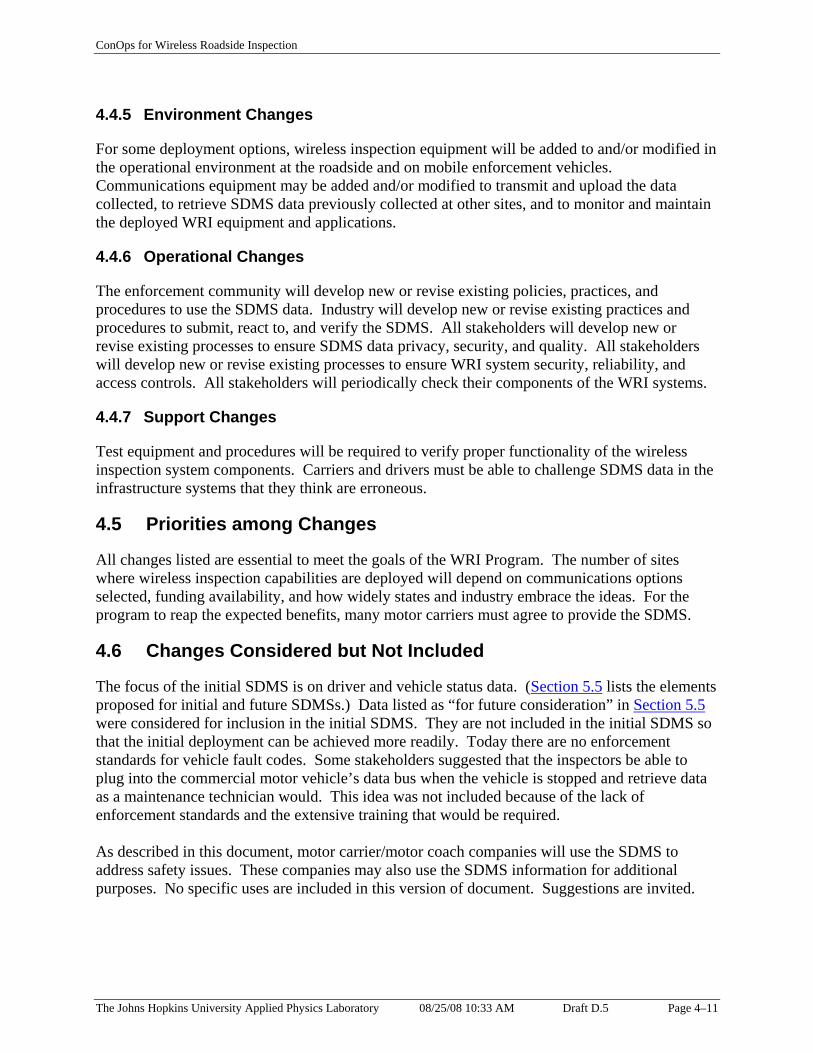
ConOps for Wireless Roadside Inspection
4.4.5 Environment Changes
For some deployment options, wireless inspection equipment will be added to and/or modified in the operational environment at the roadside and on mobile enforcement vehicles. Communications equipment may be added and/or modified to transmit and upload the data collected, to retrieve SDMS data previously collected at other sites, and to monitor and maintain the deployed WRI equipment and applications.
4.4.6 Operational Changes
The enforcement community will develop new or revise existing policies, practices, and procedures to use the SDMS data. Industry will develop new or revise existing practices and procedures to submit, react to, and verify the SDMS. All stakeholders will develop new or revise existing processes to ensure SDMS data privacy, security, and quality. All stakeholders will develop new or revise existing processes to ensure WRI system security, reliability, and access controls. All stakeholders will periodically check their components of the WRI systems.
4.4.7 Support Changes
Test equipment and procedures will be required to verify proper functionality of the wireless inspection system components. Carriers and drivers must be able to challenge SDMS data in the infrastructure systems that they think are erroneous.
4.5 Priorities among Changes
All changes listed are essential to meet the goals of the WRI Program. The number of sites where wireless inspection capabilities are deployed will depend on communications options selected, funding availability, and how widely states and industry embrace the ideas. For the program to reap the expected benefits, many motor carriers must agree to provide the SDMS.
4.6 Changes Considered but Not Included
The focus of the initial SDMS is on driver and vehicle status data. (Section 5.5 lists the elements proposed for initial and future SDMSs.) Data listed as “for future consideration” in Section 5.5 were considered for inclusion in the initial SDMS. They are not included in the initial SDMS so that the initial deployment can be achieved more readily. Today there are no enforcement standards for vehicle fault codes. Some stakeholders suggested that the inspectors be able to plug into the commercial motor vehicle’s data bus when the vehicle is stopped and retrieve data as a maintenance technician would. This idea was not included because of the lack of enforcement standards and the extensive training that would be required.
As described in this document, motor carrier/motor coach companies will use the SDMS to address safety issues. These companies may also use the SDMS information for additional purposes. No specific uses are included in this version of document. Suggestions are invited.
The Johns Hopkins University Applied Physics Laboratory 08/25/08 10:33 AM Draft D.5 Page 4–11

ConOps for Wireless Roadside Inspection
This ConOps focuses on collecting the SDMS when a vehicle encounters the following “triggers”: a roadside reader, a geofence, or a request from law enforcement. There would be merit in collecting the SDMS via upload from some other location (e.g., carrier’s facility or a remote location) periodically (e.g., daily or weekly) or on an event-driven basis (e.g., end-of-shift or end-of-trip). However, because this ConOps addresses wireless roadside inspections, the collection of the SDMS other than when the vehicle is on a road trip is not applicable and has not been included. The CSA 2010 initiative should consider this additional concept.
Several alternative concepts discussed in Reference 3 were considered but not included. The ubiquitous inspection concept as originally described is not included because, as explained above, the ConOps focuses on trip-related data collection. The supporting notion of leveraging already-deployed communications capabilities is part of this ConOps. The kiosk self-inspection concept is not included due to concerns about potential tampering and fraud. If those concerns could be ameliorated, the concept may be included in a future version.
Traffic monitoring systems, transportation analysis, and transportation planning processes may also use SDMS information after the identifiers have been removed. No specific uses are included in this version of the document. Suggestions are invited.
Technology exists to disable a vehicle remotely. There are currently no plans to use such technology in connection with the WRI system.
The Johns Hopkins University Applied Physics Laboratory 08/25/08 10:33 AM Draft D.5 Page 4–12

ConOps for Wireless Roadside Inspection
5. CONCEPTS FOR THE PROPOSED APPROACH
5.1 Background, Objectives, and Scope
The goal for wireless inspections is to improve commercial vehicle safety. New technologies and enforcement strategies could increase dramatically the number of times a commercial vehicle is examined, leading to better-targeted enforcement, safer operations, and reduced numbers of truck and bus crashes.
The concept involves the wireless collection of a safety data message set containing identifiers, driver’s log information, selected vehicle measures, and selected status data from commercial vehicles. The system must accommodate a variety of on-vehicle capabilities; some data fields in the SDMS may be blank for some vehicles. Evaluation of the information in an SDMS may result in one or more of these actions:
• The carrier or driver addresses safety issues.
• The federal system updates the carrier’s safety assessment.
• The federal system updates the driver’s safety assessment.
• A federal or state system automatically assesses compliance.
• A federal or state system issues a warning or citation.
• A roadside law enforcement or compliance system makes an enhanced screening decision.
• A roadside law enforcement system uses the SDMS in a standard inspection.
• A state system triggers a roadside interception of the vehicle.
In this chapter, we describe the proposed approach for wireless roadside inspections.
5.2 Key Concepts
The proposed approach is based on these key concepts:
• Share the SDMS to support checking the safety of commercial vehicles and drivers frequently and routinely.
• Provide flexibility for deployment.
• Use data collected to avoid safety problems, support traditional inspections, update safety assessments, and assess compliance with regulations.
• Mandated and settlement carriers will participate in WRI.
• Other carriers choose to participate voluntarily in WRI.
• Encourage voluntary participation through a tiered approach.
The Johns Hopkins University Applied Physics Laboratory 08/25/08 10:33 AM Draft D.5 Page 5–1

ConOps for Wireless Roadside Inspection
– The WRI program manager expects that the Smart Roadside initiative will establish a common structure for the data collected during a “roadside encounter” with a commercial motor vehicle (CMV). An encounter might be a wireless inspection, a traditional inspection, a screening event, a weighing event, a port/border entry event, etc.
– Define the WRI SDMS as part of that CMV roadside encounter data structure.
– Require different fields of the SDMS for each tier of participation. Tier 1 is the highest level of participation.
• Support CSA 2010 with all tiers of the SDMS.
– Existing screening programs can provide additional support for CSA 2010 with carrier and vehicle information only.
– Without any information about the driver, a dataset would not constitute a WRI SDMS tier.
The paragraphs below discuss each of these concepts further.
One key concept is that carriers will share the SDMS to support checking their vehicles and drivers frequently and routinely. Driver and vehicle safety assessments will occur frequently enough to ensure compliance while minimizing disruptions to safe and legal motor carrier transportation. Unsafe operators won’t risk driving over hours or with substandard equipment. Fewer unsafe CMV drivers and vehicles will be on the road, and crashes related to unsafe CMV drivers and vehicle defects will be reduced.
The second key concept is that the WRI system must be flexible and expandable enough to handle the volume of commercial vehicles traveling on the highways. FHWA forecasts that truck vehicle miles traveled will increase 60% by 2020. Reference 3 suggests deploying 2000-3000 roadside WRI Nodes along routes frequented by commercial vehicles to support a DSRC option for WRIs. Each jurisdiction will make its own decisions about deploying WRI system components. Carriers will decide to what extent they participate in WRIs. Some may choose to use DSRC to share the SDMS; others may use Commercial Mobile Radio Services (CMRS) or the Internet to share the SDMS.
The WRI program is focused on collecting the SDMS and making it available for subsequent use. The program will be successful only if the data collected are, in fact, used to improve safety. It is expected that use of the SDMS will be incorporated into new paradigms to help carriers and drivers avoid safety problems, help inspectors conduct traditional inspections, improve the quality of safety ratings, and assist safety investigators assessing compliance.
If the final rule enacted is consistent with the pending EOBR rule [Reference 15], motor carriers demonstrating recurrent, significant noncompliance with the HOS regulations would be required to use EOBRs. Presumably, those carriers would also be required to participate in wireless roadside inspections. Some motor carriers with unsatisfactory safety ratings enter into negotiated settlement agreements with FMCSA and commit to taking specific actions to achieve
The Johns Hopkins University Applied Physics Laboratory 08/25/08 10:33 AM Draft D.5 Page 5–2

ConOps for Wireless Roadside Inspection
full compliance with federal regulations. Presumably, some of these settlement carriers would agree to participate in wireless roadside inspections.
FMCSA expects other carriers to participate voluntarily in WRIs. One of the goals of the program is to make participation simple and inexpensive. Safe and legal carriers and drivers should see their safety assessments improve when many “good WRIs” are included in the process.
The WRI program manager expects that the Smart Roadside initiative will establish a common structure for the data collected during “roadside encounters” with commercial motor vehicles. An encounter might be a wireless inspection, a traditional inspection, a screening event, a weighing event, a port/border entry event, etc. The final definition for the WRI’s SDMS will be consistent with, or part of, that CMV roadside encounter data structure. To encourage voluntary participation, the program is defined using a tiered approach in which different fields of the SDMS are required for each tier of participation. Tier 1 is the highest level of participation. All tiers include identifiers for carrier, vehicle, and driver. Section 5.5 describes the SDMS and the tiers proposed.
All tiers of the SDMS will support CSA 2010. Existing screening programs may provide additional support for CSA 2010 by supplying only carrier and vehicle information.
5.3 Operational Policies and Constraints
FMCSA expects the existing policies and constraints identified in Section 3.2 to continue largely as is; however, some may be modified. For example, a pending rulemaking is expected to change the Electronic On-Board Recorder (EOBR) rule regarding driver duty status [Reference 8, 49 CFR 395.15]. After sufficient experience is gained with automatic fault detection by industry, enforcement, and compliance staff, FMCSA may seek regulatory authority to retrieve and use vehicle status data electronically in the inspection process; no decision has yet been made. Some jurisdictions have already passed laws concerning warning or citing drivers based on data collected by technological devices (e.g., cameras). If warnings or citations are to be issued based on wireless inspection data, similar state/local legislation and/or federal rulemaking likely will be required.
Updating a carrier’s safety assessment using SDMS data may require algorithm changes; rulemaking may be required. Using SDMS data as a factor in determining a driver’s safety assessment may also require rulemaking.
A draft list of new operational policies related to wireless roadside inspections is shown below.
OP401. Driver and vehicle safety assessments should occur frequently enough to ensure regulatory compliance while minimizing disruptions to safe and legal motor carrier transportation.
OP402. Law enforcement should verify and validate the SDMS before using it as a basis for an enforcement action.
The Johns Hopkins University Applied Physics Laboratory 08/25/08 10:33 AM Draft D.5 Page 5–3

ConOps for Wireless Roadside Inspection
OP403. Immediate enforcement action in response to a critical negative driver or vehicle measure or status [e.g., HOS, Commercial Driver’s License (CDL) status] indicated in an SDMS should be limited to steps for avoiding imminent hazardous outcomes. For non-critical violations (e.g., one low beam headlamp not operable), the carrier or driver should be given a reasonable amount of time (72 – 96 hours) to resolve and correct a negative condition. If the non-critical violation persists after the reasonable time period, then enforcement officials should take action.
A draft list of operational constraints that would govern roadside operations related to WRIs is shown below.
OC501. Designers and planners should ensure that the costs to operate and maintain a wireless inspection system (for both the private and public sectors) are justified by the benefits to be realized.
OC502. Both the CMV and a mobile enforcement vehicle participating in a WRI should be able to operate at normal speeds.
OC503. The public and private sector elements should use open standards for interfaces to exchange information and communicate with each other.
OC504. All involved should operate and maintain the system in accordance with data privacy, security, and quality requirements.
OC505. All involved should operate and maintain the system in accordance with system security, reliability, and access requirements.
OC506. The system and operational procedures should support trigger mechanisms (for the carrier to provide the SDMS) that are consistent with viable communications path options.
OC507. Public and private sector stakeholders should develop and implement strategies for retaining, cleansing, and deleting SDMS information.
OC508. Wireless inspections should be supported with commercial-off-the-shelf (COTS) roadside equipment.
OC509. No special “WRI-only” hardware should be required for installation on the CMV.
OC510. The system should operate in typical weather conditions.
OC511. The system should not interfere with other roadside or on-board systems.
OC512. The system should include the capability to validate the accuracy of the data collected. This may include comparing on-board logs to SDMS records, checking reported fault conditions using diagnostic equipment, etc. It is not necessary that every SDMS be validated. However, it is necessary that a means for validation be available upon demand.
OC513. Implementers should plan to provide access to the SDMS via common approaches adopted by U.S. DOT, the jurisdictions, and other stakeholders.
The Johns Hopkins University Applied Physics Laboratory 08/25/08 10:33 AM Draft D.5 Page 5–4

ConOps for Wireless Roadside Inspection
OC514. The system should accommodate incremental deployment within the private sector and the public sector.
OC515. The system shall accommodate the expanding number of commercial motor vehicles on the nation’s highways and increases in vehicle miles traveled.
OC516. The system should accommodate commercial motor vehicle traffic in multiple lanes.
OC517. The system should be highly reliable so that both industry and government stakeholders view the system as beneficial, trust the information shared, and are willing to deploy the supporting technology and applications.
OC518. Communications and functions for the CMV and the mobile enforcement vehicle should not distract the drivers/troopers nor pose a safety hazard to controlling the vehicles.
5.4 Description of the Proposed System
This section focuses on describing the proposed WRI system. Subsections describe the real-time and non-real-time functions of the system; major interfaces; and conceptual components of the system.
The functions listed below were derived from the users’ needs identified in Section 4.3. The source user needs (UNs) are identified in parentheses. Not all needs infer additional derived functionality.
All functions will be performed in accordance with policies and constraints.
5.4.1 Real-Time Functions
The WRI system will perform these functions in “real-time.” In this context, “real-time” means that the functions will be performed within seconds or a few minutes. To meet the real-time requirements, we expect that one or more automated processes will perform each function.
• Trigger the transmission of the SDMS. (UN205, 314, 315) The proposed triggers are via DSRC interaction between the vehicle and roadside equipment and via the vehicle crossing into a geographic area specified by the government.
• Request the SDMS for a specific vehicle from the carrier. (UN302, 304) The request may be sent by a government system to the carrier. This would require that the government system knows the association between a specific vehicle and carrier.
• Request the SDMS for a specific driver from the carrier. (UN302, 304) The request may be sent by a government system to the carrier. This would require that the government system knows the association between a specific driver and carrier.
The Johns Hopkins University Applied Physics Laboratory 08/25/08 10:33 AM Draft D.5 Page 5–5

ConOps for Wireless Roadside Inspection
• Encrypt the SDMS. (UN102) This function is required to protect personally identifiable information.
• Package the specified data into the SDMS; assure data quality. (UN101, 109, 205)
• Transmit the SDMS. (UN201, 205) The proposed methods of transmission include DSRC, CMRS, and via some back-office to back-office mechanism (e.g., Web services over the Internet).
• Notify driver, carrier, and/or service provider (as appropriate) that the SDMS has been sent. (UN204, 301)
• Receive the transmitted SDMS; authenticate SDMS transfer. (UN102, 302)
• Protect SDMS information collected, stored, disseminated, or transmitted from inadvertent alteration, spoofing, tampering, and other deliberate corruption. (UN103, 104) The system will include measures to protect data privacy and maintain system security (including protection against unauthorized access, use, modification, destruction, or denial of service) in accordance with regulations, policies, and common practice.
• Notify interested authorized users that the SDMS is available. (UN104) As examples, “interested authorized users” might include a system at a nearby weigh station or a state dispatch system in the state where the SDMS was collected.
• Verify2 the structure, format, and completeness of the SDMS. (UN101)
• Verify the internal consistency of the SDMS. (UN101)
• Verify the timeliness of the SDMS. (UN101)
• Verify that the data fields in the SDMS are within valid ranges. (UN101)
• Identify the carrier. (UN109, 301) This may occur via the SDMS itself or some other means.
• Identify the vehicle. (UN109, 301) This may occur via the SDMS itself or some other means.
• Identify the driver. (UN109, 301) This may occur via the SDMS itself or some other means.
• Evaluate the SDMS for potential safety problems; set CMV Safety Alert accordingly. (UN202, 204, 301, 302, 303, 305, 306, 307, 309, 311, 312)
• Securely share the verified SDMS and CMV Safety Alert with authorized users. (UN102, 103, 104)
• Monitor and report on critical aspects of WRI system component performance. (UN103, 106, 310) This applies primarily to government components in the WRI system.
• Control communications nodes. (UN103, 106, 310) This applies primarily to government components in the WRI system.
• Use the SDMS in electronic screening at fixed sites. (UN202, 203, 206, 305)
2 Chapter 6 provides more details about automatic verification.
The Johns Hopkins University Applied Physics Laboratory 08/25/08 10:33 AM Draft D.5 Page 5–6

ConOps for Wireless Roadside Inspection
• Use the SDMS in electronic screening from mobile enforcement units. (UN202, 203, 206, 305)
• Use the SDMS in automated safety assessment for potential immediate follow-up action. (UN202, 204, 206, 309, 311, 312, 313)
5.4.2 Non-Real-Time Functions
The WRI system will perform these functions in “non-real-time.” In this context, “non-real-time” means that the functions do not need to be performed within seconds or a few minutes. Instead, the functions may be performed over a period of several minutes to a few hours.
• Record the association between the vehicle and the carrier. (UN109, 301) The carrier notifies the government about the association either via the SDMS or by other means.
• Associate a driver with a vehicle for archival purposes. (UN109, 301) The carrier notifies the government about the association via the SDMS or by other means.
• Associate a driver with a carrier for archival purposes. (UN109, 301) The carrier notifies the government about the association via the SDMS or by other means.
• Associate the SDMS with correct carrier, vehicle, and driver records in databases for archival purposes. (UN206, 305, 306, 308, 312)
• Validate3 SDMS fields against other data sources provided by the driver, carrier, or service provider. (UN101)
• Validate SDMS fields against other data sources provided by government or law enforcement (e.g., against other observations or infrastructure database information). (UN101)
• Securely share the verified SDMS and CMV Safety Alert with authorized users. (UN102, 103, 104)
• Use the SDMS in a traditional inspection. (UN109, 202, 206, 307) The data from the SDMS should automatically update fields in the electronic inspection report.
• Use the SDMS to feed the CSA 2010 BASICs model. (UN109, 202, 206, 308)
• Use the SDMS to assess compliance with state and federal regulations. (UN109, 202, 206, 309)
• If appropriate regulatory authority exists, issue a warning or citation based on SDMS information and associated census information. (UN309)
• Use the SDMS in safety analysis and special studies. (UN109, 316)
• Support the SDMS data lifecycle (collect, catalog, review, use, archive, cleanse, delete). (UN101) If the data are subject to the Freedom of Information Act (FOIA)
3 Chapter 6 provides more details about validation.
The Johns Hopkins University Applied Physics Laboratory 08/25/08 10:33 AM Draft D.5 Page 5–7

ConOps for Wireless Roadside Inspection
[Reference 22], the system will support disclosure and tracking accordingly. The WRI system will manage the data collected throughout its lifecycle.
• Remove identifying information and make result available to authorized “non-identifiable SDMS” data users. (UN108)
• Provide a means for carrier or driver to challenge one or more SDMS records; track the process. (UN105)
• Provide a means for carrier or driver to correct erroneous SDMS records; track the process. (UN105)
• Provide a means to maintain trigger mechanisms and share related information with authorized users. (UN201, 314, 315)
• Summarize and report on all aspects of WRI system component performance. (UN103, 106, 310)
• Provide a means to maintain WRI system applications. (UN103, 106, 310)
• Provide a means to maintain WRI business rules to support SDMS verification and validation functions. (UN103, 106, 310)
5.4.3 Major System Interfaces
This section briefly describes the major WRI system interfaces. The interfaces include interactions between human users and the system, and access to services and information for automated processes.
Human users of the WRI system will be able to perform role-based functions.
• The driver will be able to enable or turn off notification regarding the transmission of the SDMS.
• The driver and carrier will be able to access the SDMSs collected about them to verify accuracy and use the information.
• The driver and carrier will be able to challenge the SDMS data; the challenge process and tools are expected to be provided by existing government systems already used for similar functions for other data collected by states and FMCSA (i.e., DataQs or its equivalent).
• The driver and carrier will be able to issue a standing request (i.e., “subscribe”) to a government system for alerts based on any SDMS that contains that driver’s or carrier’s identifiers.
• Roadside law enforcement and compliance staff may subscribe to receive alerts based on SDMS information related to nearby vehicles or drivers.
• WRI system operators will be able to monitor system components and performance data.
The Johns Hopkins University Applied Physics Laboratory 08/25/08 10:33 AM Draft D.5 Page 5–8
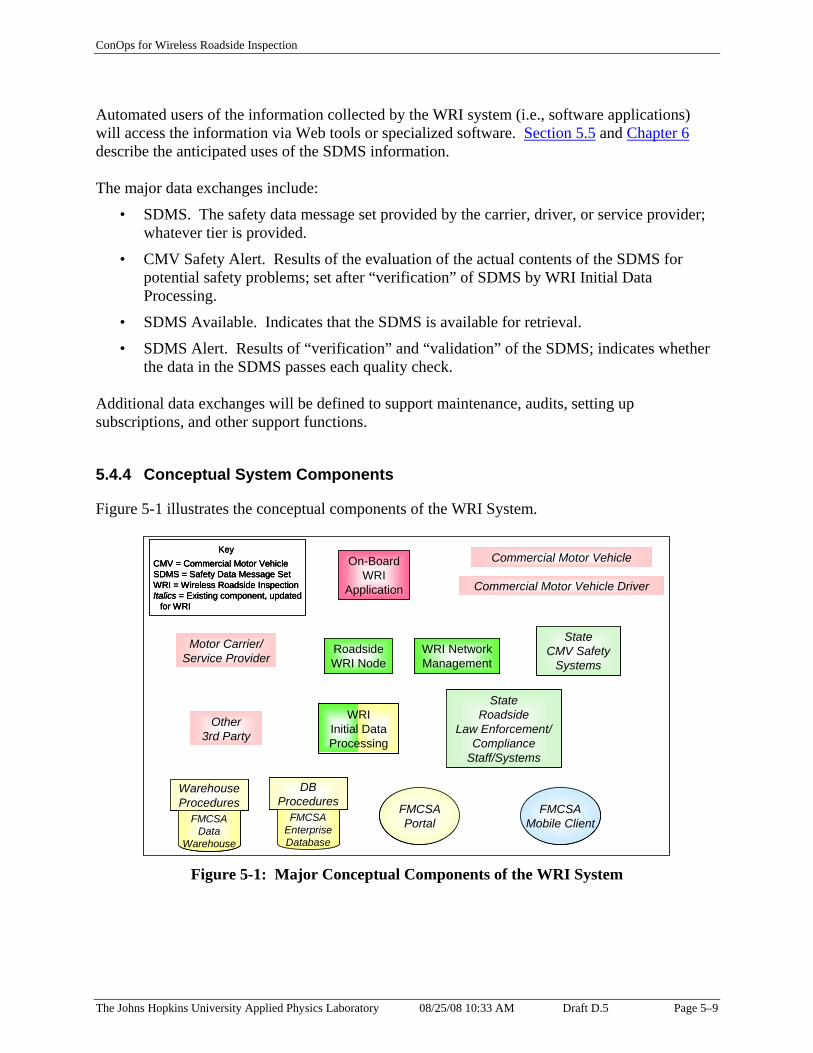
StateCMV Safety
Systems
Other 3rd Party
RoadsideWRI Node
Motor Carrier/Service Provider
StateRoadside
Law Enforcement/Compliance
Staff/Systems
FMCSAMobile Client
FMCSAPortal
On-BoardWRI
Application
ProceduresFMCSA
EnterpriseDatabase
ProceduresFMCSA
DataWarehouse
WRI NetworkManagement
Commercial Motor Vehicle
Commercial Motor Vehicle Driver
WRIInitial DataProcessing
FMCSAMobile Client
FMCSAPortal
ProceduresFMCSA
DataWarehouse
WRIInitial DataProcessing
ConOps for Wireless Roadside Inspection
Automated users of the information collected by the WRI system (i.e., software applications) will access the information via Web tools or specialized software. Section 5.5 and Chapter 6 describe the anticipated uses of the SDMS information.
The major data exchanges include:
• SDMS. The safety data message set provided by the carrier, driver, or service provider; whatever tier is provided.
• CMV Safety Alert. Results of the evaluation of the actual contents of the SDMS for potential safety problems; set after “verification” of SDMS by WRI Initial Data Processing.
• SDMS Available. Indicates that the SDMS is available for retrieval.
• SDMS Alert. Results of “verification” and “validation” of the SDMS; indicates whether the data in the SDMS passes each quality check.
Additional data exchanges will be defined to support maintenance, audits, setting up subscriptions, and other support functions.
5.4.4 Conceptual System Components
Figure 5-1 illustrates the conceptual components of the WRI System.
DBWarehouse
CMV = Commercial Motor VehicleSDMS = Safety Data Message SetWRI = Wireless Roadside InspectionItalics = Existing component, updated
for WRI
Key
State CMV Safety
Systems
Other 3rd Party
Roadside WRI Node
Motor Carrier/ Service Provider
State Roadside
Law Enforcement/ Compliance
Staff/Systems
FMCSA Mobile Client
FMCSA Portal
On-Board WRI
Application
DB Procedures
FMCSA Enterprise Database
WarehouseWarehouse Procedures
FMCSA Data
Warehouse
WRI Network Management
Commercial Motor Vehicle
Commercial Motor Vehicle Driver
CMV = Commercial Motor VehicleSDMS = Safety Data Message SetWRI = Wireless Roadside InspectionItalics = Existing component, updated
for WRI
KeyCMV = Commercial Motor Vehicle SDMS = Safety Data Message Set WRI = Wireless Roadside Inspection Italics = Existing component, updated
for WRI
Key
WRI Initial Data Processing
Figure 5-1: Major Conceptual Components of the WRI System
The Johns Hopkins University Applied Physics Laboratory 08/25/08 10:33 AM Draft D.5 Page 5–9

ConOps for Wireless Roadside Inspection
Figure 5-2 explains the color codes used in Figure 5-1.
Existing/planned FMCSA roadside component; functionality expanded for WRI
WRI-unique component (pink: private; green: state; yellow: FMCSA)
Private entity
Existing/planned state component; functionalityexpanded for WRI
Existing/planned FMCSA back-office component; functionality expanded for WRI
Color Codes
Existing/planned FMCSA roadside component; functionality expanded for WRI
WRI-unique component (pink: private; green: state; yellow: FMCSA)
Private entityPrivate entity
Existing/planned state component; functionalityexpanded for WRIExisting/planned state component; functionality expanded for WRI
Existing/planned FMCSA back-office component; functionality expanded for WRIExisting/planned FMCSA back-office component; functionality expanded for WRI
Color Codes
Figure 5-2: Color Codes
Conceptually, the major components of the WRI system include:
• Commercial Motor Vehicle – Includes the vehicle, on-board sensors, data bus, etc. Owned/managed by private entity.
• Commercial Motor Vehicle Driver – The driver (and, potentially, a co-driver). Private entity.
• Motor Carrier/Service Provider – Component that packages and transmits the SDMS upon request. May transmit SDMS from the commercial motor vehicle or back-office system. Alternatively, may forward SDMS information and/or a request for the SDMS to a 3rd party. Private entity.
• Other 3rd Party – Component that packages and transmits the SDMS upon request. Private entity.
• On-Board WRI Application – Application on the commercial vehicle that packages and transmits the SDMS. Alternatively, this application may forward SDMS information and/or a request for the SDMS to the Motor Carrier/Service Provider or Other 3rd Party. The application also notifies the driver about a WRI event. This application will reside on every vehicle that participates in the WRI program. Owned/managed by private entity.
• Roadside WRI Node – Equipment positioned along roadways that supports wireless communications, collects SDMSs from properly equipped commercial vehicles, and provides them to the rest of the WRI system. There will be one equipment set per “roadside node” on the WRI network. When the receiving equipment is on a mobile enforcement vehicle, it serves the same function. The node will provide communications, authentication, time, location determination, and limited data storage capabilities. Likely to be owned/managed by state; in some jurisdictions, may be owned/managed by a private entity, which provides the information to the state.
The Johns Hopkins University Applied Physics Laboratory 08/25/08 10:33 AM Draft D.5 Page 5–10

ConOps for Wireless Roadside Inspection
• WRI Initial Data Processing – Normally, a centralized component that authenticates SDMS inputs, verifies the SDMS information to the extent possible using automated techniques, archives the information, and distributes it for subsequent use. This component sets the SDMS Alert to report the results of the verification process. This component also evaluates the content of the SDMS and sets the CMV Safety Alert. May be state or federal entities with different business rules.
• WRI Network Management – Component that manages Roadside WRI Nodes, monitors and reports system status. Likely to be owned/managed by state; in some jurisdictions, may be owned/managed by a private entity, which provides the information to the state.
• State Roadside Law Enforcement/Compliance Staff/Systems – Components that screen commercial vehicles, communicate with drivers, and support law enforcement and compliance activities. In states that do not use all of the FMCSA Mobile Client’s (component described below) functionality (e.g., for inspections), these components provide equivalent capabilities.
• State CMV Safety Systems – Components that maintain CMV-related state credentials and safety data. Include centralized dispatch centers. Also maintain geofence coordinates and associated communications assignments.
• FMCSA Portal – Single access point for all online FMCSA business functions. Accepts SDMS inputs.
• Database (DB) Procedures/FMCSA Enterprise Database – Single authoritative data source and related procedures for real-time access to data held by FMCSA. Replaces MCMIS (Motor Carrier Management Information System), L&I (Licensing and Insurance), SAFER (Safety and Fitness Electronic Records), and EMIS (Enforcement Management Information System) databases. Includes CSA 2010 Safety Measurement System. For WRI, collects and stores the SDMS; associates the SDMS and CMV Safety Alert with the correct carrier, vehicle, and driver; validates SDMS for consistency with other sources (e.g., driver credentials); handles subscriptions for SDMS; provides SDMS in response to queries from real-time users; feeds SDMS to CSA 2010 Safety Measurement System. This component updates the SDMS Alert to report the results of the validation process.
• Warehouse Procedures/FMCSA Data Warehouse – Repository for reporting and analysis and related non-real-time procedures. Replaces A&I and Gotham. For WRI, archives the SDMS information; makes the SDMS records available for analysis; generates reports in response to analysis queries; strips identifying information from SDMS information before responding to some user groups; generates reports for transportation planners and managers.
• FMCSA Mobile Client – Provides offline business functionality. Supports inspections, reviews, audits, investigations, enforcement, and crash data collection. Replaces Aspen, CAPRI (Carrier Automated Performance Review Information), CaseRite, CDLIS (Commercial Driver’s License Information System) Access, ISS (Inspection Selection System), PIQ (Past Inspection Query), ProVu (Profile Viewer), and UFA (Uniform Fine Assessment). For WRI, uses the SDMS to populate fields in the inspection report; uses
The Johns Hopkins University Applied Physics Laboratory 08/25/08 10:33 AM Draft D.5 Page 5–11

ConOps for Wireless Roadside Inspection
identifiers from the SDMS to make automated queries for carrier, vehicle, and driver information; retrieves past SDMS information.
Figure 5-3 illustrates several major conceptual design components distributed geographically. Only a few instances of each distributed component are shown.
=== FMFMFMCCCSSSA PA PA Pooortrtrtalalal,,, DBDBDB PPPrrroooccceduedueduresresres,,, EnteEnteEnterprprpriririse Dse Dse Daaatttaaabbbaaasesese=== OnOnOn-Bo-Bo-Boaaardrdrd WWWRRRIII AAAppppppllliiicccatatatiiiooonnn === WWWRRRIII InitInitInitiaiaial Dal Dal Datatata PPPrrrocococesesessssiiingngng (r(r(regegegionionionaaalll ooorrr pppeeer jr jr juuurrriiisssdddicicictttiiiooonnn)))
=== RRRoooaaadddsisisidddeee WWWRRRIII NNNooodddeee (~(~(~111444000000 fffiiixxxed,ed,ed, 282828000000 vvviiirtuartuartual,l,l, 505050000000 mobmobmobiiillleee)))
=== WWWRRRI NetworI NetworI Networkkk MMMaaannnaaagggeeemmmententent (((rrreeegggioioionananal or pl or pl or peeerrr jjjuuurrriiisssdddicicictttiiiooonnn)))
Figure 5-3: WRI System Components Distributed Geographically
Roadside WRI Nodes or the WRI Initial Data Processing component will collect the SDMS. After initial automated verification, the WRI Initial Data Processing component will forward the SDMS and CMV Safety Alert to the FMCSA Enterprise Database via the FMCSA Portal. The state-based WRI Initial Data Processing component will also share the SDMS and CMV Safety Alert with state users. FMCSA Mobile Clients, other roadside staff and systems, and motor carriers will retrieve the SDMS via the FMCSA Portal. States (or, perhaps, private companies providing WRI node and network services) will manage the Roadside WRI Nodes via the WRI Network Management function. Sections 5.4.4.1 through 5.4.4.4 discuss the WRI-unique conceptual components in more detail. 5.4.4.1 On-Board WRI Application Component
The On-Board WRI Application component typically will interface with an EOBR that continually records driver hours-of-service information. The driver provides his/her identity information (driver license jurisdiction and ID) to the vehicle system at the start of the trip [via swiped CDL, Transportation Worker Identification Credential (TWIC), fingerprint reader, or
The Johns Hopkins University Applied Physics Laboratory 08/25/08 10:33 AM Draft D.5 Page 5–12
ConOps for Wireless Roadside Inspection
other means]. The driver enters duty status changes into the EOBR in accordance with the FMCSRs.
On-board systems continually monitor safety conditions and capture events with date-time stamps. The On-Board WRI Application component typically will interface with those systems to collect current status when assembling the SDMS.
In some cases, the driver duty status may be archived to an off-board system (e.g., a service provider’s system or the motor carrier/motor coach company’s records, which may hold information that is more than 48-hours old). Similarly, vehicle measures and status may be archived to an off-board system.
When triggered, the On-Board WRI Application will either assemble and transmit the SDMS or pass a request for the SDMS to the off-board system. This component may store the transmitted SDMS on board the vehicle so that it can be used to validate government-held records and to support troubleshooting. Alternatively, the SDMS information may be stored by a service provider or company system. Mandated and settlement carriers must archive the information used to generate the SDMS for possible subsequent access by compliance and enforcement officers.
The operational scenarios in the next chapter describe a variety of options for fulfilling the On-Board WRI Application functions. Some of the SDMS data may be assembled from on-board sources, while other data may be gathered from an off-board system and incorporated into the SDMS. The entire SDMS may be provided from an off-board system. The entire SDMS may be assembled from on-board sources.
5.4.4.2 Roadside WRI Node Component
The Roadside WRI Nodes are positioned along roadways to support wireless communications and collect SDMSs from participating commercial vehicles. Each Roadside WRI Node provides the SDMSs it collects to an associated WRI Initial Data Processing component. There will be one equipment set per “roadside node” on the WRI network. When the receiving equipment is on a mobile enforcement vehicle, it serves the same function. The node will provide communications, authentication, time, location determination, and limited data storage capabilities. The Roadside WRI Nodes are likely to be owned/managed by the state; in some jurisdictions, the nodes may be owned/managed by a private entity, which provides the information to the state.
Each Roadside WRI Node component is assigned to one WRI Network Management component for control and monitoring. The storage capacity of the Roadside WRI Node will be determined according to the jurisdiction’s implementation decisions. For example, the state may choose to have significant storage local to the node for subsequent access by authorized users, or may choose to have limited local storage because the data are uploaded for subsequent processing in real time. The Roadside WRI Node component may be designed to handle multiple lanes of commercial motor vehicle traffic or may handle a single lane.
The Johns Hopkins University Applied Physics Laboratory 08/25/08 10:33 AM Draft D.5 Page 5–13

ConOps for Wireless Roadside Inspection
5.4.4.3 WRI Initial Data Processing Component
The WRI Initial Data Processing component authenticates SDMS inputs, verifies the SDMS information to the extent possible using automated techniques, stores the information, and distributes it to other WRI components for subsequent use. This component will set the SDMS Alert to record the results of the SDMS verification step. The WRI Initial Data Processing component will check each verified SDMS to determine if some safety problem is indicated. This component will set the CMV Safety Alert after examining the SDMS information for possible safety problems.
Some jurisdictions may choose to implement the WRI Initial Data Processing component functions themselves and forward the verified SDMS and associated CMV Safety Alert to FMCSA via the Portal. Other jurisdictions may send the raw SDMS directly to FMCSA via the Portal for initial processing. In that case, the WRI Initial Data Processing functions will be performed by an FMCSA system. When a mobile enforcement unit is acting as a Roadside WRI Node, it may also perform the functions of the WRI Initial Data Processing Component so that it can operate as a stand-alone entity for real-time uses of the SDMS.
The functions of this component may be entirely or partially fulfilled by existing state systems. For instance, some states may choose to develop a new system to verify each SDMS but, once the SDMS has been verified, may evaluate the contents and share the information using an existing operational dispatch center.
5.4.4.4 WRI Network Management Component
The WRI Network Management component manages one or more Roadside WRI Nodes. In this context, “manage” means that the WRI Network Management component controls the nodes (e.g., sets the configuration or enables transfers) and monitors performance of the node network. The WRI Network Management component assembles network statistics. The WRI Network Management component reports performance data to human operators and gives those operators the opportunity to influence the network’s monitoring and control parameters. Some jurisdictions may choose to push software updates to their Roadside WRI Nodes from the WRI Network Management component. Conceptually, the WRI Network Management component monitors performance of its assigned nodes and forwards network reports to a central State CMV Safety System.
If the density of Roadside WRI Nodes is high in a particular region, multiple WRI Network Management components may be required. Conversely, adjoining jurisdictions may choose to deploy a joint WRI Network Management component to manage the Roadside WRI Nodes across multiple jurisdictions.
The Johns Hopkins University Applied Physics Laboratory 08/25/08 10:33 AM Draft D.5 Page 5–14

Additional Vehicle Measures or StatusCargo (incl. HazMat) Collision warning Container CouplingDriver performance Emissions Exhaust system Fuel systemSteering Suspension Trailer WheelsWipers Other
ConOps for Wireless Roadside Inspection
5.5 SDMS
The SDMS will focus on driver and vehicle safety information used in traditional inspections today. Three tiers are proposed:
• Tier 1 – All Level 1 inspection data that can be provided electronically (long-term: 10–15 years)
– Carrier ID, Vehicle ID, Driver ID, Shipping Document ID, Equipment ID
– Driver’s log
– Vehicle measures and status
• Tier 2 – Data to satisfy the pending EOBR rule [Reference 15] (mid-term: 5–10 years)
– Carrier ID, Vehicle ID, Driver ID
– Driver’s log
• Tier 3 – Data to verify carrier, vehicle, driver credentialing compliance (near-term: 3–5 years)
– Carrier ID, Vehicle ID, Driver ID
Figure 5-4 illustrates the draft contents of the Tier 1 SDMS.
Data Bus:SAEJ1708/SAEJ1587, SAEJ1939
Electronic On-Board Recorder (EOBR) DataDriver’s Log
(Duty Status + Location of Duty Status Changeover time)
IdentifiersDriver license jurisdiction and IDVehicle identification number (VIN)Vehicle unit numberVehicle license plate jurisdiction and IDMotor carrier/coach USDOT numberShipping document IDEquipment ID (e.g., trailer unit #)
Vehicle MeasuresBrakesTire pressureVehicle locationWeight
Vehicle StatusLightingSafety belt
Data Bus: SAEJ1708/SAEJ1587, SAEJ1939
Electronic On-Board Recorder (EOBR) Data Driver’s Log
(Duty Status + Location of Duty Status Change over time)
Identifiers Driver license jurisdiction and ID Vehicle identification number (VIN) Vehicle unit number Vehicle license plate jurisdiction and ID Motor carrier/coach USDOT number Shipping document ID Equipment ID (e.g., trailer unit #)
Vehicle Measures Brakes Tire pressure Vehicle location Weight
Additional Vehicle Measures or Status Cargo (incl. HazMat) Collision warning Container Coupling Driver performance Emissions Exhaust system Fuel system Steering Suspension Trailer Wheels Wipers Other
Vehicle Status Lighting Safety belt
Figure 5-4: Draft Tier 1 SDMS Contents
The Johns Hopkins University Applied Physics Laboratory 08/25/08 10:33 AM Draft D.5 Page 5–15

ConOps for Wireless Roadside Inspection
Data for the initial SDMS will come from the EOBR, data entry by the driver and co-driver, and standard messages defined in SAEJ1939 and SAEJ1587. The data for the initial SDMS will include:
• Identifiers
– Driver ID = jurisdiction, license identifier
– Vehicle ID = VIN, unit number (assigned by the carrier), jurisdiction and license plate ID
– Motor carrier/motor coach ID = USDOT number
– Cargo ID (shipping document ID) = bill of lading identifier
– Equipment ID assigned by the carrier (e.g., trailer unit number)
• Electronic On-Board Recorder (EOBR) Data. Driver’s log. HOS information in accordance with FMCSR Part 395, Hours of Service of Drivers
– Driver identification = name, driver identification (such as user IDs and passwords, personal identification numbers (PINs), smart cards or biometrics)
– Co-driver identification = name, co-driver identification
– Duty status
– Date and time
– Location
– Distance traveled
– Company identification = USDOT number, name
– 24-hour period start time
– Multiday basis used
– Hours in each duty status for the 24-hour period and total hours
– Vehicle identification = truck or tractor and trailer number(s)
– Shipment identification = document number(s) or name of shipper and commodity
• Vehicle Measures
– Date and time
– Brakes
– Tire pressure
– Weight
– Vehicle location
The Johns Hopkins University Applied Physics Laboratory 08/25/08 10:33 AM Draft D.5 Page 5–16

ConOps for Wireless Roadside Inspection
• Vehicle Status
– Lighting
– Safety belt
Appendix D lists potential sources for the specific items in the SDMS.
For future consideration, as capabilities expand, eventually the SDMS also may include:
• Other Identifier Data
– Shipper ID
– Commodity ID
• Other Measures and Status about the Vehicle
– Container
– Coupling
– Fuel system
– Steering
– Suspension
– Trailer
– Wheels
– Wipers
– Other electronic components
• Advanced Monitoring System Data
– Collision warning
– Driver performance
• Security Data
– Container status
– Cargo status
• Environmental Data
– Emissions
– Exhaust system
The Johns Hopkins University Applied Physics Laboratory 08/25/08 10:33 AM Draft D.5 Page 5–17

ConOps for Wireless Roadside Inspection
5.6 Modes of Operation
The proposed modes of operation for the WRI system are the same as those listed in Section 3.4 for today’s commercial vehicle-roadside systems. The modes are mutually exclusive for a component of the system.
5.6.1 Operational/Normal
In this mode, all components are functioning normally. The functions listed earlier in this chapter can be performed. The main uses of the SDMS can occur (addressing safety issues, updating the carrier’s and driver’s safety assessments, automatically assessing compliance, issuing a warning or citation, making an enhanced screening decision, using the SDMS in a standard inspection, triggering a roadside interception of the vehicle).
5.6.2 Degraded
In this mode, some component (or multiple components) is (or are) not functioning normally. This may cause the WRI process to be conducted differently or to use less-than-optimal data. For example, a Roadside WRI Node equipment malfunction could prevent the collection of SDMSs from vehicles that would normally communicate via that path. If one or more components are in this mode and other components are in operational mode, the operational components will continue to function normally to the extent possible.
5.6.3 Maintenance
In the maintenance mode, some component (or multiple components) is (or are) offline for scheduled or unscheduled maintenance. In this mode, staff may run diagnostics to determine detailed status of the component, or use troubleshooting tools to pinpoint problems, etc. This mode will be used for routine updates of applications, system parameters (e.g., geofence coordinates or business rules), and hardware repairs or upgrades. Parameter changes that affect multiple components should be applied as rapidly as practical (preferably within 30 minutes). If one or more components are in this mode and other components are in operational mode, the operational components will continue to function normally to the extent possible.
5.6.4 Training
In this mode, the system is used to train operators. Artificial conditions may be created, and data collected are not entered into the operational databases. Processes across the system must recognize and accommodate this mode. If one or more components are in this mode and other components are in operational mode, the operational components will continue to function normally to the extent possible.
The Johns Hopkins University Applied Physics Laboratory 08/25/08 10:33 AM Draft D.5 Page 5–18

ConOps for Wireless Roadside Inspection
5.6.5 Idle/Off-line
In this mode, some component (or multiple components) is (or are) idle or off-line. No data collection or subsequent processing occurs beyond the idle or off-line component. If one or more components are in this mode and other components are in operational mode, the operational components will continue to function normally to the extent possible.
5.7 User Classes
Primary users of the WRI system include:
• Automated processes
• WRI system operators
– Driver
– Enforcement/compliance staff
– Motor carrier/motor coach company staff
– Other 3rd party staff
• WRI system maintainers
– Driver
– Enforcement/compliance staff
– Motor carrier/motor coach company staff
– Other 3rd party staff
Secondary users include:
• Trainer/trainee
• Safety analyst
• Mechanic
• Border crossing official
• Traffic manager
• Planner
• Yard manager
The stakeholders involved in achieving the vision for WRIs include:
• Motor carriers (trucking and motor coach companies)
• Drivers of commercial vehicles
• Commercial vehicle manufacturers
The Johns Hopkins University Applied Physics Laboratory 08/25/08 10:33 AM Draft D.5 Page 5–19

ConOps for Wireless Roadside Inspection
• Technology vendors
• Service providers
• Other 3rd parties
• Federal government – U.S. Department of Transportation Federal Motor Carrier Safety Administration (FMCSA)
• State government – the agencies and their contractors that will design, build, and maintain the distributed components
• State and local law enforcement and their contractors
The Johns Hopkins University Applied Physics Laboratory 08/25/08 10:33 AM Draft D.5 Page 5–20

ConOps for Wireless Roadside Inspection
6. OPERATIONAL SCENARIOS
This chapter describes a representative set of operational scenarios. The scenarios reflect the functions of the WRI system from the users’ points of view. This set of scenarios does not cover all possible ways the system might operate. This set of scenarios does not cover all possible choices that carriers and jurisdictions might make as they design, deploy, and operate the system. Instead, the scenarios describe a range of possibilities. The scenarios explain how the system will support different kinds of users with different capabilities.
For the pilot phase of the WRI project, the team will choose typical and stressful scenarios to help demonstrate that the system works in real operational environments, will identify viable candidate technologies, and will define potential deployment strategies.
For purposes of this chapter, the scenarios assign particular functions to the conceptual components of the system. When FMCSA and states implement their parts of the system, they may choose to assign the functions to existing applications or to other new elements of the WRI system.
Some carriers contract with service providers to help track and manage their operations. This chapter uses the term “carrier” when describing carrier-related steps in the scenarios. The carrier may choose to perform the functions directly or have a service provider act on its behalf.
Figure 6-1 illustrates a generic, simplified data flow for WRI data. It shows different options for how the SDMS and related information might flow among WRI system components.
The Johns Hopkins University Applied Physics Laboratory 08/25/08 10:33 AM Draft D.5 Page 6–1

FMCSAMobile Client
WRIInitial DataProcessing
FMCSAPortal FMCSA
EnterpriseDatabase
DBProcedures
FMCSAData
Warehouse
WarehouseProceduresFMCSA
Portal FMCSAEnterpriseDatabase
DBProcedures
FMCSAData
Warehouse
WarehouseProcedures
ConOps for Wireless Roadside Inspection
KeySDMS (raw)SDMS (verified)SDMS (verified and validated)
Key SDMS (raw)SDMS (raw) SDMS (verified)SDMS (verified) SDMS (verified and validated)SDMS (verified and validated)
State CMV Safety
Systems
Roadside WRI NodeMotor Carrier
State Roadside Law Enforcement/
Compliance Staff/Systems
FMCSA Mobile Client
On-Board WRI
Application
Commercial Motor Vehicle
WRI Initial Data Processing
FMCSA Portal FMCSA
Enterprise Database
DB Procedures
FMCSA Data
Warehouse
Warehouse Procedures
SDMS
SDMS, CMV Safety Alert SDMS Alert
Data for SDMS
SDMS Available, CMV Safety Alert SDMS, SDMS Alert
1
3
4
2
4
4
3
2 2
2a
2
4
1
3
4
Figure 6-1: Generic, Simplified Data Flow
Step 1 shows the CMV sending the data for the SDMS to the On-Board WRI Application and/or the Motor Carrier. The WRI Program will not define a standard for this interface.
Step 2 shows the On-Board WRI Application or the Motor Carrier sending the SDMS to the Roadside WRI Node or the WRI Initial Data Processing component. Step 2a shows the Roadside WRI Node sending the SDMS it has collected to the WRI Initial Data Processing component. The WRI Program will define a standard for the Step 2/2a interface and for all subsequent interfaces shown.
Step 3 shows the WRI Initial Data Processing component sending the SDMS, associated CMV Safety Alert, and SDMS Alert to the FMCSA systems. In some cases, the WRI Initial Data Processing component may also send the data to the State CMV Safety Systems. In some cases, the State CMV Safety Systems may send the data to State Roadside Law Enforcement/ Compliance Staff/Systems.
Step 4 shows the FMCSA systems sending SDMS Available and CMV Safety Alert to the Motor Carrier, FMCSA Mobile Client, State CMV Safety Systems, and State Roadside Law Enforcement/Compliance Staff/Systems. If the recipient is interested, its system can retrieve the
The Johns Hopkins University Applied Physics Laboratory 08/25/08 10:33 AM Draft D.5 Page 6–2

ConOps for Wireless Roadside Inspection
SDMS and SDMS Alert. In some cases, the State CMV Safety Systems may send the data to State Roadside Law Enforcement/Compliance Staff/Systems.
Please read specific sections below to understand variations on and nuances of the simplified flows shown in Figure 6-1. The line styles in Figure 6-1 show different stages of verification and validation of the SDMS and are described in the key below.
• The thin black line reflects the raw SDMS.
• The thicker blue line indicates that the raw SDMS has completed the automated verification checks.
• The thickest green line indicates that the SDMS has completed all automated verification and validation checks.
6.1 Major Operational Scenarios
This section describes several major operational scenarios. Section 6.2 describes in more detail steps that are common across several scenarios.
6.1.1 Unstaffed Automated Safety Enforcement, Compliance, and Assessment
Today, most jurisdictions can perform limited fully automated commercial vehicle safety enforcement, compliance, and assessment checks. The most widespread automatic functionality is to weigh and measure the vehicle. At some sites, additional sensors measure radiological or chemical signatures. If the site equipment can identify the vehicle and carrier automatically, an automated system can access and check historical safety data and current credentials status.
After the WRI system is deployed, the carrier will submit an SDMS for a particular vehicle when triggered. The WRI Initial Data Processing component will evaluate the SDMS automatically to determine if an unsafe situation exists. If so, according to the communications capabilities in the jurisdiction where the vehicle is traveling, the statewide operations/law enforcement dispatch center will be alerted and nearby enforcement staff will be informed. The SDMS and CMV Safety Alert will be uploaded to the FMCSA Enterprise Database via the FMCSA Portal. If the carrier subscribes to receive automatic notifications, the company will be notified.
The FMCSA systems and/or State CMV Safety Systems will determine whether the information from the SDMS indicates a safety or credentials violation. Compliance checks may include:
• Verify the carrier’s authority to operate
• Determine if the vehicle is properly registered and operating within permitted parameters (e.g., weight, geofencing, load type, etc.)
• Determine if the vehicle is on an allowable route (check against permit)
• Determine if the driver’s license indicates the driver is authorized to operate the vehicle being driven
The Johns Hopkins University Applied Physics Laboratory 08/25/08 10:33 AM Draft D.5 Page 6–3

ConOps for Wireless Roadside Inspection
• Determine if the driver is medically qualified, as indicated by the medical certificate
• Assess HOS compliance
• Check the vehicle measures and status for indications of possible safety problems using Level 1 inspection criteria
If the government agency has appropriate authority, in some cases it may issue a warning or citation based on the automated assessment of the SDMS. The FMCSA systems will use the SDMS to feed the CSA 2010 Operational Model and update the carrier and driver safety assessments. The SDMS will be stored in the FMCSA Data Warehouse for future analysis.
A special case of this automated safety assessment occurs when the Roadside WRI Node is collocated with other equipment at a virtual weigh station. Virtual weigh stations are established for a variety of purposes depending on the priorities and needs of each jurisdiction. Typical purposes include safety enforcement, data collection, security (e.g., homeland security, theft deterrence), size and weight enforcement, to help target enforcement activities, and to spread the enforcement net. These sites are not staffed and may use a variety of sensor components to collect data. After the WRI system is deployed, SDMS information collected wirelessly will be used to augment and expedite the identification of the carrier and vehicle, identify the driver, augment the safety assessment of the vehicle, and check the safety status of the driver.
6.1.2 Screening Support
As a vehicle approaches a staffed fixed or temporary weigh station, it is “screened” to determine whether to pull it in for further examination.
Today screening typically is accomplished using various sensor technologies to assess the weight and size of the vehicle. Some sites also identify the vehicle and carrier electronically using 915 MHz DSRC, using optical character recognition, or manually (a person reads the license plate and/or USDOT number). Once the vehicle and carrier are identified, the screening system can access infrastructure data to factor in the safety record of the associated carrier, registration status of the vehicle, etc., to determine whether to pull in the vehicle for inspection.
After the WRI system has been deployed, SDMS information collected as a vehicle approaches a staffed weigh station will expedite vehicle and carrier identification to support traditional screening. Additionally, the driver will be identified, enabling the screening system to look up the driver’s license status. If a Tier 2 or Tier 1 SDMS is provided, driver hours-of-service (HOS) data will be reported and evaluated. If a Tier 1 SDMS is provided, selected vehicle measures will be reported and evaluated. The screening system will use the carrier, vehicle, and driver identifiers to look up credentials status and safety history. The credentials status, safety history, HOS data, and selected vehicle measures will enable improved screening. The SDMS information will augment other data that are used already in the screening process [e.g., weight measured by weigh-in-motion (WIM) or static scales].
The Johns Hopkins University Applied Physics Laboratory 08/25/08 10:33 AM Draft D.5 Page 6–4
ConOps for Wireless Roadside Inspection
The SDMS and CMV Safety Alert will be uploaded to the FMCSA Enterprise Database via the FMCSA Portal. If the carrier subscribes to receive automatic notifications, the company will be notified. The FMCSA systems will use the SDMS to feed the CSA 2010 Operational Model and update the carrier and driver safety assessments. The SDMS will be stored for future analysis in the FMCSA Data Warehouse.
A special case of this usage can occur when the screening “site” is mobile. See below for additional information.
6.1.3 Traditional Inspection Support
Qualified inspectors traditionally conduct inspections at fixed or temporary sites using permanently installed and/or portable equipment. All those variations for human-in-the-loop inspections will continue.
When WRI capabilities are deployed, SDMS information will be used to augment and expedite the traditional inspection process. The SDMS data will be presented to the inspector for automatic inclusion in the inspection report. The inspector could validate the integrity of the SDMS data by comparing them to data collected directly from the vehicle and driver.
The SDMS and CMV Safety Alert will be uploaded to the FMCSA Enterprise Database via the FMCSA Portal. If the carrier subscribes to receive automatic notifications, the company will be notified. The FMCSA systems will use the SDMS to feed the CSA 2010 Operational Model and update the carrier and driver safety assessments. The SDMS will be stored in the FMCSA Data Warehouse for future analysis. To support draft policy OP403, the officer should retrieve past SDMS information for the vehicle and driver. If a negative condition detected earlier exists beyond the reasonable amount of time to resolve, the officer may take enforcement action.
A special case of this can occur when the inspection “site” is mobile. See below for additional information.
6.1.4 Mobile Safety Check
Increasingly, mobile enforcement vehicles are outfitted with equipment to exchange data and query infrastructure systems and to conduct some level of safety inspection.
Today, the enforcement officer usually relies on visual information to identify the carrier (USDOT number on the side of the vehicle) and vehicle (license plate). The identifiers can be used to query for additional information. If the vehicle is stopped, temporary equipment can be deployed to weigh the vehicle and conduct an inspection.
After the WRI system is deployed, the mobile enforcement vehicle will also be configured to receive and use the SDMS. In some cases, the CMV will submit SDMS information when the mobile enforcement vehicle acts as a Roadside WRI Node. If the mobile enforcement vehicle is
The Johns Hopkins University Applied Physics Laboratory 08/25/08 10:33 AM Draft D.5 Page 6–5

ConOps for Wireless Roadside Inspection
located at a geofence boundary, the carrier will submit the SDMS when that boundary is encountered. In other cases, the officer will request the SDMS after identifying the vehicle. The SDMS will provide the carrier, vehicle, and driver ID. The officer’s system will use those identifiers to look up credentials status and safety history. If a Tier 2 or Tier 1 SDMS is provided, driver HOS data will be reported and evaluated. If a Tier 1 SDMS is provided, selected vehicle measures will be reported and evaluated. The credentials status, safety history, HOS data, and selected vehicle measures will assist the officer in deciding whether to conduct an inspection. Ideally, the officer’s system will make an automated assessment of the SDMS and infrastructure data and provide a “red” or “green” indicator to the officer. If the officer decides to pull the CMV over, the officer will signal the driver accordingly. If the officer conducts an inspection, the SDMS data will be presented for automated inclusion in the inspection report. [Note: this is a special case of the screening support usage and the traditional inspection support usage of the SDMS.]
A variation on this scenario is that a vehicle provides an SDMS, and the automated unstaffed assessment scenario described above in Section 6.1.1 detects a possible safety problem. A state dispatch center sends a message to downstream mobile enforcement units to intercept that vehicle. The officer would know what vehicle to look for and would already have the SDMS for that vehicle. When the vehicle approaches and is identified, the officer could signal it to pull over.
The officer’s system will upload the SDMS and CMV Safety Alert to the FMCSA Enterprise Database via the FMCSA Portal. If the carrier subscribes to receive automatic notifications, the company will be notified. The FMCSA systems will use the SDMS to feed the CSA 2010 Operational Model and update the carrier and driver safety assessments. The SDMS will be stored in the FMCSA Data Warehouse for future analysis.
6.1.5 Routine Safety Analysis or Special Study
FMCSA will store the SDMSs in the FMCSA Data Warehouse for use in safety analyses and special studies. Government and private safety analysts will be able to access the SDMS information via the FMCSA Portal and tools provided. The sheer numbers of SDMS records envisioned should enrich the data sources available to assess driving patterns, driver HOS compliance, and vehicle measurements and status data. The SDMS may provide additional insight about factors that are related to and predictive of future crashes.
In some analyses, it may be useful to maintain the association of the SDMS with a particular carrier, vehicle, and driver. In other analyses, those associations may not be important.
A carrier will be able to access its own SDMS records to monitor driver and vehicle performance. A carrier may also use its collection of SDMS records to identify trends and patterns of behavior. The collection of SDMS information may help carriers improve safety.
The WRI system will control access to SDMS records based on access rules and users’ roles. This applies not only to this scenario, but to all scenarios. Some safety analysts may be
The Johns Hopkins University Applied Physics Laboratory 08/25/08 10:33 AM Draft D.5 Page 6–6

ConOps for Wireless Roadside Inspection
authorized to see any SDMS with all identifications intact. Others may be able to see the data only after the driver’s ID is removed.
FMCSA Data Warehouse tools will facilitate the analysis efforts. For instance, analysts may need to be able to request SDMS records:
• For a particular carrier (vehicle, or driver; or set of carriers, vehicles, or drivers) over a particular period of time
• Within a particular geographic region over a particular period of time
• For drivers (or carriers, or vehicles) that match some set of criteria (e.g., authorized to drive a particular class of vehicle)
• That show a particular vehicle status code (or range of values for a particular vehicle measure)
• That were collected at a particular set of Roadside WRI Nodes
Those queries are simply examples, not an exhaustive (or necessarily correct) list. The idea is that tools in the FMCSA Data Warehouse should support query and report writing capabilities for analysis that includes SDMS data. FMCSA will work with stakeholders to provide the desired query, report, and analysis capabilities to leverage the collection of SDMS information to maximize the safety benefits.
6.1.6 Carrier Use of SDMS
Carriers will be able to retrieve and review SDMSs that contain information about entities associated with their own companies. FMCSA will provide access via the FMCSA Portal. States may also choose to provide access to SDMSs via their systems. A carrier may establish a standing request (i.e., a subscription) to be notified when FMCSA processes an SDMS involving the company. The initial concept is that the notification is a two-step process. The FMCSA systems will send a notification to the carrier (SDMS Available and CMV Safety Alert), and the carrier then will retrieve the SDMS, if desired. Other approaches may be considered. For instance, a large carrier may choose a daily notification of all SDMSs processed instead of receiving individual notifications for each SDMS processed. Alternatively, a carrier may choose to be notified only if the CMV Safety Alert indicates a problem.
FMCSA expects carriers to take action to resolve safety problems indicated in the SDMS. For example, the actions may include training, improved driver scheduling, or vehicle maintenance. Mandated and settlement carriers will archive SDMS information they provide via their own systems so that enforcement and compliance staff can validate the information.
Drivers may also choose to be informed each time SDMSs about their trips are sent. The On-Board WRI Application would provide the information. The driver could take action to resolve safety problems indicated in the SDMS.
The Johns Hopkins University Applied Physics Laboratory 08/25/08 10:33 AM Draft D.5 Page 6–7
ConOps for Wireless Roadside Inspection
As with other data, if the carrier finds an error in the SDMS data held by FMCSA, the WRI system will provide a means to challenge the information. (Today, DataQs provides that capability.) FMCSA will provide SDMS-data-challenge tools via the FMCSA Portal.
6.1.7 Use of SDMS in Transportation Planning and Management
The SDMS may provide information useful to transportation planners and managers. SDMS information used for transportation planning and management should not include any identifiers or sensitive information about the driver. Depending on interest from planners and managers, it may be appropriate to produce periodic sets of data or reports. For instance, it might be useful to provide a quarterly report that summarizes how many CMVs traveled on a particular roadway span. FMCSA will work with transportation managers and planners to provide useful reports.
6.1.8 Managing the WRI Network
The network management function associated with collecting the SDMS information may be centralized or distributed. Some jurisdictions may manage the Roadside WRI Nodes from multiple locations. Others may have one central WRI Network Management component within the jurisdiction. Others may choose to implement a multi-jurisdictional WRI Network Management component, with one central site managing the Roadside WRI Nodes for more than one jurisdiction in a region.
In general, the network management scenarios involve control of the Roadside WRI Nodes, providing operations and maintenance information to network management staff, and reporting network status information to the designated State CMV Safety System component. These scenarios also involve distributing software and parameter updates to Roadside WRI Nodes as needed. As one example, if a state changes a geofence boundary because of a special event, the parameter change would be pushed to the Roadside WRI Nodes.
6.2 Common Steps
Many operational scenarios involve some of the same steps. This section discusses some of those common steps and suggests options for how they might be executed.
6.2.1 Options for Submitting the SDMS
The motor carrier will submit the SDMS. For the information in the SDMS to be useful for real-time operations, the information should be current. Today some service providers reconstruct the driver’s log upon demand either entirely from data uploaded throughout the trip to a central repository or from a mix of data stored on-board and off-board. Those options are acceptable for WRI support, as long as the information is current, complete, and accurate.
The Johns Hopkins University Applied Physics Laboratory 08/25/08 10:33 AM Draft D.5 Page 6–8

ConOps for Wireless Roadside Inspection
If the driver chooses to be notified, the On-Board WRI Application would be responsible for any human-machine interface concerning the SDMS. If the SDMS data indicate an unsafe condition exists, the driver would be informed via in-cab notification. Designers and implementers should consider audible messages and text messages that can be converted on-board to an audible message.
The designers and implementers of the WRI system will consider several different communications options. Here are a few candidates:
• Vehicle-to-roadside (transceiver/transponder). In this option, the vehicle is equipped with a transceiver (e.g., 5.9 GHz DSRC) or transponder (e.g., 915 MHz DSRC). The jurisdiction through which the vehicle travels deploys compatible Roadside WRI Nodes that can communicate with the on-board systems. When the vehicle encounters a Roadside WRI Node, the communications link is established. The On-Board WRI Application transmits the SDMS to the Roadside WRI Node. In some cases, the On-Board WRI Application may assemble the SDMS entirely from on-board data. In other cases, the On-Board WRI Application may retrieve part of the SDMS (e.g., older parts of the driver’s log) from an off-board archive. If desired, the On-Board WRI Application will notify the driver when it transmits the SDMS.
In this case, the encounter between the vehicle and the Roadside WRI Node triggers the submission of the SDMS. The Roadside WRI Node authenticates the communications exchange and passes the SDMS to its associated WRI Initial Data Processing component.
• Carrier to government systems (Commercial Mobile Radio Service). In this option, the CMV communicates routinely with the motor carrier’s office. Communications occur via Commercial Mobile Radio Services (CMRS). The vehicle routinely sends SDMS information and, potentially, other vehicle status data to the motor carrier. When the On-Board WRI Application detects that the vehicle has encountered a Wireless Roadside Inspection “trigger” (initially envisioned to be either a geofence boundary or a Roadside WRI Node), the vehicle notifies the carrier that the SDMS should be transmitted. If desired, the On-Board WRI Application will notify the driver about the activity. If the stored SDMS data are stale, the motor carrier retrieves fresh SDMS information from the vehicle. The carrier then assembles the SDMS and sends it either to the Roadside WRI Node that triggered the event or to the appropriate WRI Initial Data Processing component.
In this case, either crossing a geofence boundary or encountering a Roadside WRI Node triggers the submission of the SDMS. Conceptually, the communications between the carrier’s system and the WRI Initial Data Processing component could be via CMRS, over the Internet, or by some other means.
• Enforcement identifies vehicle and requests SDMS. This option provides support for CSA 2010. It does not require any special applications on board the CMV. This option primarily pertains to operations from a mobile enforcement vehicle, although it could also apply at a fixed location. In this option, law enforcement identifies the CMV and requests that the carrier submit the SDMS for that vehicle. Law enforcement may identify the CMV using different mechanisms. For example, an officer or automated
The Johns Hopkins University Applied Physics Laboratory 08/25/08 10:33 AM Draft D.5 Page 6–9

ConOps for Wireless Roadside Inspection
system may capture the license plate ID (manually or via automated tools such as a License Plate Reader) or capture an ID from an RFID tag. The officer/system sends a request for the SDMS of that vehicle to the carrier associated with the vehicle.
Note: This approach actually requires both the vehicle ID and an identifier for the associated carrier. One possible approach is that law enforcement knows in advance what carrier is associated with the vehicle ID captured so that the request can be sent to the correct carrier. Conceptually, some central system would manage a database that maintains the association between carriers and their vehicles. For purposes of this document, we assume that central system is the FMCSA Enterprise Database and its associated database procedures. Via the FMCSA Portal, the carrier would maintain a list of its vehicles. The carrier would also specify where and how SDMS requests for those vehicles should be sent. A second approach would be for law enforcement to capture both the vehicle and carrier ID. Then the only information needed in the central system would be where and how SDMS requests for that carrier should be sent.
When the carrier receives the SDMS request, it determines whether fresh SDMS information is needed. If so, the carrier retrieves fresh SDMS information from the vehicle. The carrier then assembles the SDMS and sends it to the appropriate WRI Initial Data Processing component. If desired, the carrier will also notify the driver via the On-Board WRI Application.
In this case, an enforcement officer or system triggers the request for the SDMS. That request triggers the carrier to submit the SDMS. Conceptually, the communications between the carrier’s system and the system that requests the SDMS could be via CMRS, over the Internet, or by some other means. Similarly, the communications between the carrier’s system and the WRI Initial Data Processing component could be via CMRS, over the Internet, or by some other means.
Stakeholders may define other options for consideration.
6.2.2 Options for Initial Processing of the SDMS and Setting CMV Safety Alerts
As described earlier, conceptually, the WRI Initial Data Processing component is a centralized component that authenticates SDMS inputs, verifies the SDMS information to the extent possible using automated techniques, stores the information, and distributes it for subsequent use. This component also evaluates the content of the SDMS and sets the CMV Safety Alert. There may be state, regional, and federal instances of this component.
If a state deploys Roadside WRI Nodes to collect the SDMS from vehicles, it would be practical for those nodes to send the SDMS to a state or regional WRI Initial Data Processing component. To support the option for carriers to submit the SDMS from their back-office systems, it would be practical for there to be a single WRI Initial Data Processing “address” that all carriers could use. That address may be for a single federal WRI Initial Data Processing component. Or, the address could be, effectively, the front end of a pointer system that links to multiple state or
The Johns Hopkins University Applied Physics Laboratory 08/25/08 10:33 AM Draft D.5 Page 6–10

ConOps for Wireless Roadside Inspection
regional WRI Initial Data Processing components. In that case, each WRI Initial Data Processing component would be responsible for managing the SDMSs for a set of carriers.
In concept, each instance of the WRI Initial Data Processing component would perform the same basic functions, although the business rules for verifying the SDMS may differ. What can be verified depends on what is included in the SDMS itself, how the submission is triggered, and the business rules implemented by the WRI Initial Data Processing component.
Automatic verification of the SDMS may include:
• Check the date/time stamp in the SDMS versus the date/time when the submission was triggered
• Check the geographic location reflected in the SDMS versus the location where the submission was triggered
• Check the structure and format of each identifier (does it match the definitions of acceptable identifiers for the jurisdiction)
• For a Tier 1 or Tier 2 SDMS, check the structure and format of the driver’s log
• For a Tier 1 or Tier 2 SDMS, check that each field in the driver’s log is in expected range
• For a Tier 1 SDMS, check the structure and format of each vehicle measure
• For a Tier 1 SDMS, check that each vehicle measure value is in expected range
• For a Tier 1 SDMS, check the structure and format of each vehicle status parameter
• For a Tier 1 SDMS, check that each vehicle status parameter is in expected range
Stakeholders may define other SDMS verification steps for consideration. The verification can only occur when the corresponding data item is included in the SDMS. Note that the FMCSA systems will subsequently attempt to validate the SDMS as well, checking the contents against other sources.
The WRI Initial Data Processing component will set the SDMS Alert to indicate what verification rule or rules failed, if any.
After the verification step is complete, the WRI Initial Data Processing component will determine if the data indicate any safety problems and will set the CMV Safety Alert accordingly. The safety check will be as complete as possible given the data included in the SDMS and whether the data passed the verification step. Data that failed the verification step will not be included in the safety check step. The safety check process may include:
• Check the carrier ID against a targeted carrier list, if any
• Check the vehicle ID against targeted vehicle list, if any
• Check the driver ID against a targeted driver list, if any
• For a Tier 1 or Tier 2 SDMS, check the driver’s log for compliance with hours-of-service (HOS) rules
The Johns Hopkins University Applied Physics Laboratory 08/25/08 10:33 AM Draft D.5 Page 6–11

ConOps for Wireless Roadside Inspection
• For a Tier 1 SDMS, check the vehicle measures and status for indication of possible safety problem using Level 1 inspection criteria
Stakeholders may define other SDMS safety evaluation concepts for consideration.
If the SDMS suggests a possible safety problem, the WRI Initial Data Processing component will set the CMV Safety Alert to indicate the nature of the problem(s).
6.2.3 Options for Sharing the SDMS and CMV Safety Alerts
When the SDMS is collected near a staffed site, the WRI Initial Data Processing component may send the verified SDMS, CMV Safety Alert, and SDMS Alert to the nearby State Roadside Law Enforcement/Compliance Staff/Systems and/or to the State CMV Safety Systems. The primary motivation for this approach is so that the SDMS can be used for real-time applications such as e-screening.
To support WRI data collection, validation, storage, and subsequent use of the SDMS data, FMCSA will update the FMCSA Portal, FMCSA Enterprise Database and related procedures, and FMCSA Data Warehouse and related procedures. The FMCSA systems will provide the SDMS to authorized users such as the motor carrier, FMCSA Mobile Client, State CMV Safety Systems, and State Roadside Law Enforcement/Compliance Staff/Systems.
Conceptually, the task of storing the SDMS is assigned (within the collecting jurisdiction) to the WRI Initial Data Processing component, at least for a brief time. The storage options will depend on the design and capacity of the component, and on applicable requirements for saving the SDMS. Jurisdictions will make choices depending on their own objectives. The functionality provided by other federal and state commercial motor vehicle safety data systems may also influence a jurisdiction’s decisions. The main motivation for a jurisdiction to store the SDMS is to facilitate verification, system monitoring, troubleshooting, and maintenance activities. A jurisdiction may also choose to store SDMSs for intrastate operators, rather than forwarding them to FMCSA.
The jurisdiction that collects the SDMS will also store it. FMCSA will also store SDMS information, conceptually in the FMCSA Enterprise Database for real-time use. In today’s environment, the data would probably be stored in the Motor Carrier Management Information System (MCMIS). FMCSA will also archive the SDMS for non-real-time use, conceptually in the FMCSA Data Warehouse.
At least part of each SDMS has a limited shelf life. For instance, the vehicle measures and status information provide a real-time picture of selected safety information related to the vehicle at the moment the data were captured. Later in time, the conditions may be different, so the SDMS may no longer be relevant. However, if enforcement actions are taken based on the vehicle information in the SDMS, the WRI system may need to store the SDMS indefinitely so that the data are available for case prosecution. The driver’s log data in the SDMS could be used to compare to records provided by the motor carrier during a compliance review.
The Johns Hopkins University Applied Physics Laboratory 08/25/08 10:33 AM Draft D.5 Page 6–12

ConOps for Wireless Roadside Inspection
The data may be stored and archived in its original form or may be split into segments (e.g., corresponding to carrier, vehicle, and driver segments). For subsequent analysis, the storage system should support reconstructing the original SDMS if requested. All SDMS information should be stored, whether the data were verified or not. Utilities should be executed periodically to archive, clean up, and delete obsolete SDMS information.
There are several models for sharing the SDMS, regardless of whether the FMCSA systems or state systems are doing the sharing:
• Push to known users via a subscription process. The subscription may be based on specific data criteria. For instance, Carrier XYZ may subscribe to receive all SDMS records corresponding to its USDOT number. The subscription may be fulfilled every time an SDMS is processed that meets the data criteria or may be fulfilled on some periodic basis (e.g., daily).
• Push to known users upon receipt or on some periodic basis. In this case, all the SDMS information may be sent to a user, regardless of the data contents of the messages.
• Pull by authorized users by querying via a Web browser
• Pull by authorized users via Web services or some system-to-system application
For non-real-time use, the initial concept is that FMCSA systems will use a two-step process: (1) push SDMS Available and CMV Safety Alert to the user and (2) the user retrieves the SDMS itself. Designers and implementers may choose other approaches.
In all cases, the WRI system must protect the data it makes available. This includes protecting privacy, ensuring information security, and tracking which data are provided to which users. In general, only verified SDMS information will be made available for subsequent processing. In some cases (e.g., troubleshooting, training, or testing), SDMS information that did not pass the automated verification steps may be made available for subsequent processing. Unverified data must be clearly marked as such.
6.2.4 Validating the SDMS
Automatic validation of the SDMS, as defined here, means an automated process that checks the contents of the SDMS against other sources. As described here, all the SDMS validation functions are assigned to the FMCSA systems. Designers and implementers may choose to assign some validation functions to state systems and some to the FMCSA systems.
Automatic validation of the SDMS may include:
• Checking the validity of each identifier (does it match an actual identifier from the corresponding authoritative source; e.g., CDL system for driver ID, FMCSA enterprise database for carrier ID)
• Checking that each entity identified is “active” according to the authoritative source
The Johns Hopkins University Applied Physics Laboratory 08/25/08 10:33 AM Draft D.5 Page 6–13
ConOps for Wireless Roadside Inspection
• Comparing the carrier ID in the driver’s log with other data in SDMS and/or with other observations
• Comparing the vehicle ID in the driver’s log with other data in SDMS and/or with other observations
• Comparing the driver ID in the driver’s log with other data in SDMS and/or with other observations
Stakeholders may define other SDMS validation steps for consideration. The validation can only occur when the corresponding data item is included in the SDMS. The FMCSA systems will update the SDMS Alert to indicate what rule or rules failed, if any. Subsequent processes that use the SDMS information may elect to use only validated data.
People may perform additional manual validation steps by examining other sources of information.
6.2.5 Feeding the BASICs Model
FMCSA is developing a new operational model through the Comprehensive Safety Analysis 2010 (CSA 2010) initiative. The operational scenarios assume that FMCSA will use the SDMS in the CSA 2010 Behavioral Analysis and Safety Improvement Categories (BASICs). The BASICs represent “behaviors categories that can lead to crashes: unsafe driving, fatigued driving, driver fitness, controlled substances and alcohol, vehicle maintenance, improper loading/cargo securement, and crash history.” [Reference 4] Figure 6-2 illustrates the CSA 2010 Operational Model.
The Johns Hopkins University Applied Physics Laboratory 08/25/08 10:33 AM Draft D.5 Page 6–14

SAFETY DATA
UNFIT SUSPENSION
Motor CarrierComplianceActivities &
Crash Reports
MEASUREMENTOn-Road Safety
Performance(BASICs)
SAFETYMANAGEMENT
PROBLEMSIntervention Process
Unsafe DrivingFatigueDriver FitnessDrugs and AlcoholVehicle MaintenanceLoading/Cargo SecurementCrash History
INTERVENTIONInvestigative:
Targeted Roadside InspectionsOff site InvestigationOn site Investigation
Corrective:Warning LetterCooperative Safety PlanNotice of ViolationNotice of ClaimConsent Agreement
SAFETYEVALUATIONSAFETY DATA
UNFIT SUSPENSION
Motor CarrierComplianceActivities &
Crash Reports
MEASUREMENTOn-Road Safety
Performance(BASICs)
SAFETYMANAGEMENT
PROBLEMSIntervention Process
Unsafe DrivingFatigueDriver FitnessDrugs and AlcoholVehicle MaintenanceLoading/Cargo SecurementCrash History
INTERVENTIONInvestigative:
Targeted Roadside InspectionsOff site InvestigationOn site Investigation
Corrective:Warning LetterCooperative Safety PlanNotice of ViolationNotice of ClaimConsent Agreement
SAFETYEVALUATION
ConOps for Wireless Roadside Inspection
SuspendOperations
--
SDMS
SuspendOperations
--
SAFETY DATA
UNFIT SUSPENSION
Motor Carrier Compliance Activities &
Crash Reports
Suspend Operations
MEASUREMENT On-Road Safety
Performance (BASICs)
SAFETY MANAGEMENT
PROBLEMS Intervention Process
Unsafe Driving Fatigue Driver Fitness Drugs and Alcohol Vehicle Maintenance Loading/Cargo Securement Crash History
--
INTERVENTION Investigative:
Targeted Roadside Inspections Off-site Investigation On-site Investigation
Corrective: Warning Letter Cooperative Safety Plan Notice of Violation Notice of Claim Consent Agreement
SAFETY EVALUATION
SDMS
Figure 6-2: SDMS Feeding CSA 2010 Operational Model
A Tier 1 or Tier 2 SDMS contains the driver’s log. The hours-of-service data in the driver’s log could feed the Fatigue BASIC. A Tier 1 SDMS contains vehicle measures and status. Those data could feed the Vehicle Maintenance BASIC. The driver ID provided in any SDMS could be used to determine whether the driver has a valid license and is medically qualified. License status and medical qualification could feed the Driver Fitness BASIC.
According to the CSA 2010 Operational Model, the BASICs will be used in the Carrier and Driver Safety Measurement Systems. This activity will also include associating the information in the SDMS with the appropriate carrier, vehicle, and driver.
6.3 Non-Nominal Scenarios Many conditions may cause a disruption in the nominal operational scenarios described in Section 6.1. This section addresses some of those non-nominal situations.
The SDMS may be incomplete. A motor carrier may choose to provide some, but not all, of the full SDMS. Or, some temporary problem may produce an incomplete SDMS. Routine processing should occur based on the tier of SDMS provided, regardless of what tier was expected from that carrier. As long as the identifiers are present in the message, the initial processing step should occur. If the SDMS is missing data, the automated verification should
The Johns Hopkins University Applied Physics Laboratory 08/25/08 10:33 AM Draft D.5 Page 6–15

ConOps for Wireless Roadside Inspection
proceed to the extent possible. If one or more identifiers are missing, it will probably be impossible to attribute the SDMS to those entities that are not identified. Incomplete messages should be flagged via the SDMS Alert for possible subsequent investigation.
The SDMS may not be transferred successfully. Hardware or communications failures may interrupt or prevent successful transfer of the SDMS from the source to the destination. If part of the message is transferred, it may be possible to process it as if it were an incomplete SDMS. Some failures may corrupt the message or prevent subsequent processing. The On-Board WRI Application, WRI Network Management, and WRI Initial Data Processing components of the system should monitor for failures and report them. The appropriate component should report failures to the driver and/or motor carrier (for a failure to complete the transfer from the On-Board WRI Application component or carrier’s system) or to the network management staff (for a failure to complete the transfer from the Roadside WRI Node component). If the carrier’s system fails to complete the transfer of the SDMS, the initiating system should send an error report to the destination, if possible. The system that receives an SDMS transfer error indication should log the error and attempt to re-establish normal communications with the sender. Designers will select a standard approach for establishing, authenticating, and handshaking to support SDMS transfers. Error reports should be logged for possible subsequent investigation.
The SDMS information may fail one or more verification or validation checks. Section 6.2.2 identified several steps in the automated verification of the SDMS. Section 6.2.4 identified several steps in the automated validation of the SDMS. If one or more of these checks fails, the failure should be flagged via the SDMS Alert. Subsequent processes that use the SDMS should take into account the success of the verification and validation steps.
The SDMS may be stored incorrectly or not at all. The system components that store the SDMS may experience problems. For example, data fragments, rather than complete records, may be stored. Or, data from an SDMS may be associated with the incorrect entities. Procedures and tools to check the integrity of the SDMS information stored should be executed on a regular basis and should report problems detected. Staff should address the problem conditions as soon as practical.
The SDMS information may not be shared as planned. The system components that make the SDMS information available for subsequent processing may fail to fulfill subscriptions correctly. They may also fail to provide the data to all authorized users who request it. The search tools may fail to find all records that match the query parameters. The SDMS-sharing components should monitor their own performances and, to the extent possible, track and record problems. Users should be able to report problems with accessing the data. Staff should address the problem conditions as soon as practical.
Government authorities may suspect potential fraudulent activity. Repeated validation failures (or other conditions) may indicate potential fraudulent activity. Government staff will use the analysis tools described in Section 6.1.5 to investigate. As part of the investigation, government staff may also contact the carrier to review SDMS information archived by the carrier.
The Johns Hopkins University Applied Physics Laboratory 08/25/08 10:33 AM Draft D.5 Page 6–16

ConOps for Wireless Roadside Inspection
7. SUMMARY OF IMPACTS
This ConOps describes a framework for operational processes and appropriate technologies intended to support WRIs. As the ConOps is used, it will be important for participants and observers to capture information about the actual impacts of modified operational processes and using these concepts. Anticipated impacts are described below.
7.1 Operational Impacts
The proposed operational changes are likely to affect users, developers, and maintenance staff during operation of the proposed system.
Interfaces As described in the sample scenarios, new interfaces are proposed between commercial vehicles and roadside equipment, and between carriers and government systems. Typically, the roadside equipment will be a new device installed to collect the SDMS from passing commercial vehicles, or may be an inspector’s handheld computer or a system mounted in a mobile enforcement vehicle. Carriers will establish new interfaces to share the SDMS with government systems. Some carriers will send the SDMS to government systems from their own systems. Others will send the SDMS from the vehicle to a roadside system. Carriers will retrieve the SDMS from government systems.
In some jurisdictions, states will upload the SDMS from their systems to FMCSA via the FMCSA Portal. State systems will retrieve the SDMS via the FMCSA Portal. Alerts based on the SDMS may be sent in real time from the State CMV Safety Systems and FMCSA systems to a statewide operations/law enforcement dispatch center, to State Roadside Law Enforcement/Compliance Staff/Systems, and to the company responsible for the safety of the commercial vehicle. Information from the SDMS may be provided to e-screening, inspection, or other distributed state systems.
A processed SDMS will be used by the FMCSA systems that compute performance measures for motor carrier/motor coach companies and drivers. The updated measures will be provided to those who typically access them today. The company and driver will also have access to the processed SDMS so that they can evaluate its accuracy and validity.
Diagnostic data to assess the health of on-board equipment used to collect information for the SDMS will be available to authorized users (e.g., driver, company maintenance staff, law enforcement). Diagnostic data to assess the health of Roadside WRI Nodes will be available to authorized users (e.g., state roadside equipment maintenance staff, law enforcement).
The Johns Hopkins University Applied Physics Laboratory 08/25/08 10:33 AM Draft D.5 Page 7–1

ConOps for Wireless Roadside Inspection
Procedures Staff will evaluate and update, as needed, existing procedures for e-screening, inspection, and enforcement and compliance activities to take advantage of the new data source. Maintenance procedures will be required for the new equipment, parameters, and applications. Procedures to upload and retrieve the SDMS information may be required. Automated data quality checks will be needed to verify the integrity of the SDMS before use.
Data collection and input The WRI concept focuses on increased data collection and use of those data. The volume of SDMS information collected will have a significant impact on state and federal CMV safety data systems. FMCSA estimates that approximately 300 million SDMSs could be collected annually.
Data retention In collaboration with motor carriers, state agencies and FMCSA will need to develop SDMS data retention policies. The policies should make provisions for data collection, verification, validation, and use, as well as for opportunities to challenge the data. Policies, procedures, and tools to periodically check data integrity and purge stale data should be developed.
Modes of operation As described in Chapter 5, the modes of operation are expected to include Operational/Normal, Degraded, Maintenance, Training, and Idle/Off-line. These modes are equivalent to operational modes for today’s commercial vehicle operators, developers, roadside law enforcement/compliance staff, and system maintainers.
Budget Implementing the WRI concept will affect the budget for the key user groups (carriers, state agencies, federal agency – FMCSA). Development, deployment, and ongoing operations and maintenance costs will be experienced by the stakeholders. Actual costs will depend on choices made.
Risks For safe and legal operators, deployment of the WRI system should decrease the risk of being stopped for an inspection. For unsafe operators, the system may increase the risk of being stopped for an inspection.
Security/Information Assurance To meet the information assurance requirements, appropriate controls must be applied to protect the WRI information and systems. The controls are described below. Text was extracted from Reference 11.
The Johns Hopkins University Applied Physics Laboratory 08/25/08 10:33 AM Draft D.5 Page 7–2

ConOps for Wireless Roadside Inspection
“Management/Administrative Controls: Management and administrative controls define the human factors of security. These controls involve all levels of personnel within an organization and determine which users have access to which resources and information by such means as:
• Configuration Management
• Asset Management
• Personnel Hiring and Separation of Duties
• Certification and Accreditation
• Risk Management
• Training and Awareness
Operational Controls: Operational controls are those controls that are implemented on an ongoing basis and applied to the day-to-day operation of information systems. Examples of operational controls are:
• Personnel Security
• Incident Response and Reporting
• Security Awareness Training
• Security Documentation
• Data Integrity
• System Maintenance
• Contingency Planning
• Production, Input/Output Controls
• Physical and Environmental Security
Technical Controls: Technical controls use technology as a basis for controlling the access and usage of sensitive data throughout a physical structure and over a network. Technical controls are far-reaching in scope and encompass such technologies as:
• Encryption
• Smart Cards
• Network Authentication
• Access Control Lists (ACLs)
• Host Integrity and Auditing
• Firewalls
• Intrusion Detection”
The Johns Hopkins University Applied Physics Laboratory 08/25/08 10:33 AM Draft D.5 Page 7–3

ConOps for Wireless Roadside Inspection
7.2 Organizational Impacts
Carriers, state agencies, and FMCSA will institute training for operators and maintenance staff. Maintaining the additional On-Board WRI Application, Roadside WRI Nodes, and the infrastructure systems that will handle the SDMS information may require additional staff. As law enforcement paradigms shift to take advantage of the information, re-training will be needed. Regulatory action may be needed to use the SDMS in enforcement activities and to update safety assessments.
7.3 Impacts During Development
The WRI Program is planning to conduct pilot and field operational test phases to test the concepts expressed in this document. During those phases, participants will be involved in studies and planning sessions, system installation and test activities, special data collection and analysis activities, and changes to routine operations.
If the decision is made to deploy the WRI system nationwide, each state will develop a plan for deploying the capabilities within its jurisdiction. If the system is to augment existing facilities, those facilities will be affected during development, installation, and testing.
The Johns Hopkins University Applied Physics Laboratory 08/25/08 10:33 AM Draft D.5 Page 7–4

ConOps for Wireless Roadside Inspection
8. ANALYSIS OF THE CONOPS
8.1 Summary of Improvements
The WRI system is expected to improve commercial vehicle safety by:
• Providing additional information to target unsafe operators
• Deterring unsafe behavior by increasing the likelihood that a vehicle and driver will be inspected
Collecting driver and vehicle safety status information more often will also result in more accurate safety performance measures.
8.2 Disadvantages and Limitations
Data collection, in and of itself, does not directly affect on-the-road behavior. Collecting hundreds of millions of SDMSs will have a significant impact on existing information systems in the states and at FMCSA. The desired safety improvements will be achieved only if a significant number of commercial vehicles and jurisdictions participate in wireless roadside inspections.
8.3 Alternatives and Tradeoffs Considered
More extensive versions of the SDMS were considered. As explained earlier, the initial SDMS is defined to capture the information considered critical to assess commercial motor vehicle and driver safety.
Different information flow paths for the SDMS are identified and are expected to be adopted. The concepts could have focused on only one communications option. However, multiple options will be explored in the pilot phase of the project to determine feasibility.
This ConOps focuses on collecting the SDMS when a vehicle on the road encounters a “trigger” (envisioned to be a roadside node, geofence boundary, or enforcement request) during a trip rather than at some other place or time. There would be merit in collecting the SDMS via upload from some other location (e.g., carrier’s facility or a remote location) periodically (e.g., daily or weekly) or on an event-driven basis (e.g., end-of-shift or end-of-trip). However, since this ConOps addresses wireless roadside inspections, the collection of the SDMS other than when the vehicle is on a road trip is not applicable and has not been included. The CSA 2010 initiative should consider this additional concept.
Several alternative concepts discussed in Reference 3 were considered but not included. The ubiquitous inspection concept as originally described is not included because, as explained above, the ConOps focuses on trip-related data collection. The supporting notion of leveraging
The Johns Hopkins University Applied Physics Laboratory 08/25/08 10:33 AM Draft D.5 Page 8–1
ConOps for Wireless Roadside Inspection
already-deployed communications capabilities is part of this ConOps. The kiosk self-inspection concept is not included due to concerns about potential tampering and fraud. If those concerns can be ameliorated, the concept may be included in a future version.
The Johns Hopkins University Applied Physics Laboratory 08/25/08 10:33 AM Draft D.5 Page 8–2

ConOps for Wireless Roadside Inspection
9. ACRONYMS AND ABBREVIATIONS
This section provides an alphabetical list of acronyms and their expanded names. Chapter 10 gives definitions and/or descriptions of selected terms.
A&I Analysis & Information
ACL Access Control List
ASPEN not an acronym
BASICs Behavioral Analysis and Safety Improvement Categories
CAPRI Carrier Automated Performance Review Information
CDL Commercial Driver’s License
CDLIS Commercial Driver’s License Information System
CFR Code of Federal Regulations
CMRS Commercial Mobile Radio Services
CMV Commercial Motor Vehicle
CMVSA Commercial Motor Vehicle Safety Act
COMPASS Creating Opportunities, Methods, and Processes to Secure Safety
ConOps Concept of Operations
COTS Commercial-Off-The-Shelf
CSA Comprehensive Safety Analysis
CSM Carrier Safety Measurement
CVIEW Commercial Vehicle Information Exchange Window
CVO Commercial Vehicle Operations
CVSA Commercial Vehicle Safety Alliance
DB Database
DOE Department of Energy
DOT Department of Transportation
DSM Driver Safety Measurement
DSRC Dedicated Short-Range Communication(s)
EMIS Enforcement Management Information System
EOBR Electronic On-Board Recorder
FAF Freight Analysis Framework
The Johns Hopkins University Applied Physics Laboratory 08/25/08 10:33 AM Draft D.5 Page 9–1

ConOps for Wireless Roadside Inspection
FHWA Federal Highway Administration
FIPS Federal Information Processing Standards
FMCSA Federal Motor Carrier Safety Administration
FMCSR Federal Motor Carrier Safety Regulation
FOIA Freedom of Information Act
HazMat Hazardous Materials
HM Hazardous Materials
HMR Hazardous Materials Regulation
HOS Hours-of-Service
HRCQ Highway Route Controlled Quantities
IEC International Electrotechnical Commission
IEEE Institute of Electrical and Electronics Engineers
IFTA International Fuel Tax Agreement
IRP International Registration Plan
ISO International Organization for Standardization
ISS Inspection Selection System
JHU/APL The Johns Hopkins University Applied Physics Laboratory
L&I Licensing and Insurance
LCV Longer Combination Vehicle
LIFIS Licencia Federal Information System (Mexico)
LPR License Plate Reader
LTCCS Large Truck Crash Causation Study
MCMIS Motor Carrier Management Information System
MCSAP Motor Carrier Safety Assistance Program
NAS North American Standard
NIST National Institute for Standards and Technology
Nlets International Justice and Public Safety Information Sharing Network
NORPASS North American Preclearance and Safety System
NPRM Notice of Proposed Rulemaking
OCxxx Draft Operational Constraint number
OOS Out Of Service
OPxxx Draft Operational Policy number
The Johns Hopkins University Applied Physics Laboratory 08/25/08 10:33 AM Draft D.5 Page 9–2

VII
ConOps for Wireless Roadside Inspection
OS/OW Oversize/Overweight
PIN Personal Identification Number
PIQ Past Inspection Query
ProVu (Motor Carrier) Profile Viewer
QC Query Central
RAS Remote Access Server
RFID Radio Frequency Identification
RODS Record of Duty Status
SAE Society of Automotive Engineers (The Engineering Society for Advancing Mobility Land Sea Air and Space)
SAFER Safety and Fitness Electronic Records
SAFETYNET not an acronym
SCT Department of Communications and Transportation (Mexico)
SDMS Safety Data Message Set
SPE Skill Performance Evaluation
TWIC Transportation Worker Identification Credential
UFA Uniform Fine Assessment
UNxxx User Need number
USDOT U.S. Department of Transportation
Vehicle Infrastructure Integration
VIN Vehicle Identification Number
VMT Vehicle Miles Traveled
WAVE Wireless Access in Vehicular Environments
WIM Weigh in Motion
WRI Wireless Roadside Inspection
The Johns Hopkins University Applied Physics Laboratory 08/25/08 10:33 AM Draft D.5 Page 9–3

ConOps for Wireless Roadside Inspection
This Page Intentionally Blank
The Johns Hopkins University Applied Physics Laboratory 08/25/08 10:33 AM Draft D.5 Page 9–4

ConOps for Wireless Roadside Inspection
10. GLOSSARY
This section defines, in common language, some of the terms relevant to this document. These definitions are not intended to be legally binding.
Associated Inspection Station: commercial vehicle weigh and inspection facilities associated with a set of WRI roadside equipment; may be fixed or mobile, permanent or temporary.
Availability: “The characteristic of an item expressed by the probability that it will be operational at a randomly selected future instant in time.” (IEEE Std 100-1996)
Commercial Motor Vehicle: a heavy truck or motor coach.
Database Procedures/FMCSA Enterprise Database: conceptually, a WRI system component. Single authoritative data source and related procedures for real-time access to data held by FMCSA. Replaces MCMIS (Motor Carrier Management Information System), L&I (Licensing and Insurance), SAFER (Safety and Fitness Electronic Records), and EMIS (Enforcement Management Information System) databases. Includes CSA 2010 Safety Measurement System. For WRI, collects and stores the SDMS; associates the SDMS and CMV Safety Alert with the correct carrier, vehicle, and driver; validates SDMS for consistency with other sources (e.g., driver credentials); handles subscriptions for SDMS; provides SDMS in response to queries from real-time users; feeds SDMS to CSA 2010 Safety Measurement System. This component updates the SDMS Alert to report the results of the validation process.
Driver’s Duty Status: a description of the driver’s activities related to the hours-of-service regulations. According to current regulations, the possibilities are off duty, sleeper berth, driving, or on duty not driving.
Driver’s Log: the record of a driver’s duty status changes (also known as Record of Duty Status or RODS) over time. May be in paper or electronic form (via electronic on-board recorder).
Driver OOS Rate: the percentage of driver inspections that found serious violations and resulted in the issuance of a driver OOS order.
FMCSA Mobile Client: conceptually, a WRI system component. Provides offline business functionality. Supports inspections, reviews, audits, investigations, enforcement, and crash data collection. Replaces Aspen, CAPRI (Carrier Automated Performance Review Information), CaseRite, CDLIS (Commercial Driver’s License Information System) Access, ISS (Inspection Selection System), PIQ (Past Inspection Query), ProVu (Profile Viewer), and UFA (Uniform Fine Assessment). For WRI, uses the SDMS to populate fields in the inspection report; uses identifiers from the SDMS to make automated queries for carrier, vehicle, and driver information; retrieves past SDMS information.
The Johns Hopkins University Applied Physics Laboratory 08/25/08 10:33 AM Draft D.5 Page 10–1

ConOps for Wireless Roadside Inspection
FMCSA Portal: conceptually, a WRI system component. Single access point for all online FMCSA business functions. Accepts SDMS inputs.
FMCSA Systems: systems managed and maintained by FMCSA to store and analyze safety data. These are centralized infrastructure systems. In today’s environment, these would include, for example, MCMIS, L&I, A&I, and SAFER. After COMPASS is fully deployed, this would include the FMCSA Portal, Database Procedures/FMCSA Enterprise Database, Warehouse Procedures/FMCSA Data Warehouse, and the FMCSA Mobile Client.
Hours of Service: usually refers to the section of federal regulations that sets maximum hours for driving and minimum hours for resting.
Motor Carrier/Motor Coach Company: the company responsible for safety of the commercial vehicle.
Identifiers (IDs): identifiers associated with entities of interest on the road. Includes driver ID, vehicle ID, carrier ID.
Mobile Enforcement: mobile systems used for roadside enforcement, compliance, and assessment of commercial vehicles.
On-Board WRI Application: conceptually, a WRI system component. Application on the commercial vehicle that packages and transmits the SDMS. Alternatively, this application may forward SDMS information and/or a request for the SDMS to the Motor Carrier/Service Provider or Other 3rd Party. The application also notifies the driver about a WRI event. This application will reside on every vehicle that participates in the WRI program. Owned/managed by private entity.
Roadside WRI Node: conceptually, a WRI system component. Equipment positioned along roadways that supports wireless communications and collects SDMSs from properly equipped commercial vehicles and provides them to the rest of the WRI system. There will be one equipment set per “roadside node” on the WRI network. When the receiving equipment is on a mobile enforcement vehicle, it serves the same function. The node will provide communications, authentication, time, location determination, and limited data storage capabilities. Likely to be owned/managed by state; in some jurisdictions, may be owned/managed by a private entity, which provides the information to the state.
State CMV Safety Systems: conceptually, WRI system components. Maintain CMV-related state credentials and safety data. Include centralized dispatch centers. Also maintain geofence coordinates and associated communications assignments.
State Roadside Law Enforcement/Compliance Staff/Systems: conceptually, WRI system components. Screen commercial vehicles, communicate with drivers, and support law enforcement and compliance activities. In states that do not use all of the FMCSA Mobile
The Johns Hopkins University Applied Physics Laboratory 08/25/08 10:33 AM Draft D.5 Page 10–2

ConOps for Wireless Roadside Inspection
Client’s (component described above) functionality (e.g., for inspections), these components provide equivalent capabilities.
Sensor: a device that measures or detects some physical condition such as motion, weight, light, biological entities, chemical elements, or a radiological signature.
Statewide Operations/Law Enforcement Dispatch: systems managed and maintained by states to collect and evaluate safety data in order to dispatch resources to address critical issues.
Traditional Inspection Station: commercial vehicle weigh and inspection facility that is associated with a Roadside WRI Node; may be fixed or mobile, permanent or temporary.
Vehicle OOS Rate: the percentage of vehicle inspections that found serious violations and resulted in the issuance of a vehicle OOS order.
Virtual Weigh Station: equipment suite on the roadside that collects commercial vehicle weight, size, and other data that are associated with Roadside WRI Node; may capture information to facilitate e-screening for targeted enforcement; may be fixed or mobile, permanent or temporary.
Warehouse Procedures/FMCSA Data Warehouse: conceptually, a WRI system component. Repository for reporting and analysis and related non-real-time procedures. Replaces A&I and Gotham. For WRI, archives the SDMS information; makes the SDMS records available for analysis; generates reports in response to analysis queries; strips identifying information from SDMS information before responding to some user groups; generates reports for transportation planners and managers.
WRI Initial Data Processing: conceptually, a WRI system component. Normally, a centralized component that authenticates SDMS inputs, verifies the SDMS information to the extent possible using automated techniques, archives the information, and distributes it for subsequent use. This component sets the SDMS Alert to report the results of the verification process. This component also evaluates the content of the SDMS and sets the CMV Safety Alert. May be state or federal entities with different business rules.
WRI Network Management: conceptually, a WRI system component. Manages Roadside WRI Nodes, monitors and reports system status. Likely to be owned/managed by state; in some jurisdictions, may be owned/managed by a private entity, which provides the information to the state.
The Johns Hopkins University Applied Physics Laboratory 08/25/08 10:33 AM Draft D.5 Page 10–3

ConOps for Wireless Roadside Inspection
This Page Intentionally Blank
The Johns Hopkins University Applied Physics Laboratory 08/25/08 10:33 AM Draft D.5 Page 10–4

ConOps for Wireless Roadside Inspection
APPENDIX A. CVSA LEVELS OF INSPECTION
From Understanding the North American Standard Inspection Program, http://www.cvsa.org/documents/inspectionprogrambrochure.pdf. [Reference 18].
The Johns Hopkins University Applied Physics Laboratory 08/25/08 10:33 AM Draft D.5 Page A–1

ConOps for Wireless Roadside Inspection
This Page Intentionally Blank
The Johns Hopkins University Applied Physics Laboratory 08/25/08 10:33 AM Draft D.5 Page A–2

ConOps for Wireless Roadside Inspection
APPENDIX B. CURRENT SYSTEM DESCRIPTIONS
B.1 FMCSA Systems
FMCSA provides this information on their Overview - Core Information Systems Web site.
A&I (Analysis and Information) – A&I Online is a web-based tool designed to provide quick and efficient access to descriptive statistics and analyses regarding commercial vehicle, driver, and carrier safety information. It is used by Federal and State enforcement personnel, as well as the motor carrier industry, insurance companies, and the general public. A&I was developed with Oracle.
ASPEN – ASPEN is an application that collects all the commercial driver/vehicle roadside inspection details. It utilizes several other applications that pull data from remote sources – ISS, PIQ, CDLIS Access, and QC. It also includes communication features to electronically transfer inspection details to SAFER and/or SAFETYNET.
CAPRI (Compliance Analysis and Performance Review Information) – CAPRI is used for preparing Compliance Reviews and Safety Audits, as well as specialized cargo tank facility reviews, and hazardous material (HM) shipper reviews. CAPRI includes worksheets for collecting (1) hours of service data, (2) driver qualification data, and (3) drug and alcohol compliance data. It also creates the preliminary carrier safety fitness rating and various reports for motor carriers. It electronically transfers data to SAFETYNET and/or MCMIS.
CaseRite – CaseRite assists in the creation of legal enforcement cases for Federal prosecution of the Federal Motor Carrier Safety Regulations (FMCSRs) and the Federal Hazardous Materials Regulations (FHMRs) violations. These case reports, after review and management approval, are uploaded to EMIS.
CDLIS (Commercial Driver’s License Information System) – CDLIS was created to fulfill a requirement under the Commercial Motor Vehicle Safety Act (CMVSA) of 1986 and has been in full operation since April 1992. It serves as a clearinghouse that each of the 51 jurisdictions (the 50 states and the District of Columbia) can check before issuing a commercial driver's license. CDLIS helps to ensure that only one license or CDL is issued to each driver nationwide. It also ensures that all convictions are reported to the licensing state and made part of the driver's record.
CDLIS Access – The CDLIS Access software is used to retrieve driver status and conviction history reports via a RAS (remote access server) connection to CDLIS. It accepts driver query data from ASPEN or CAPRI.
EMIS (Enforcement Management Information System) – EMIS is a web-based application used to monitor, track, and store information related to FMCSA enforcement actions. It manages and tracks all data associated with notifying the carrier, monitoring the carrier's response,
The Johns Hopkins University Applied Physics Laboratory 08/25/08 10:33 AM Draft D.5 Page B–1

ConOps for Wireless Roadside Inspection
determining whether further compliance action is required, and generating reports for various Headquarters, Service Center, and Division staff. It is the authoritative source for FMCSA enforcement data. Inputs include data from CaseRite and data entry.
ISS (Inspection Selection System) – The ISS is the primary tool used on the roadside to screen motor carrier vehicles and determine the usefulness of conducting an inspection. ISS returns the carrier snapshot, which includes critical safety performance indicators. It is linked to ASPEN to auto-populate name and address data fields and initiate the inspection. ISS uses a local database, but individual carrier data can be updated via a RAS connection to SAFER. Database updates are also available monthly via a web service.
CDLIS SCT – Mexican safety information system.
L&I (Licensing and Insurance) – The L&I system is a client-server and web-based application with both public and private access. It is used to enter and display licensing and insurance information regarding authorized for-hire motor carriers, freight forwarders, and property brokers. It is the authoritative source for FMCSA licensing and insurance data. L&I is part of the registration process.
MCMIS (Motor Carrier Management Information System) – MCMIS is an information system that captures data from field offices through SAFETYNET, CAPRI, and other sources. MCMIS utilizes an Oracle database with a web front-end access. It is a source for FMCSA inspection, crash, compliance review, safety audit, and registration data.
PIQ (Past Inspection Query) – The PIQ accesses a national database of recent inspection reports. Currently this database contains inspection report data for the previous 60 days; however, this will be expanded in the near future to include 180 days. PIQ retrieves an exact facsimile of any previous inspection reports.
ProVu – ProVu is a viewer which allows Federal, State, and private industry users to electronically analyze standard motor carrier safety profile reports available from the Federal Motor Carrier Safety Administration. This application displays nearly every data element found on the hard-copy version of the carrier profile in an easy-to-understand format that can be sorted, filtered, and optimized by users.
Query Central (QC) – QC is a web-based application that retrieves safety compliance and enforcement data on commercial motor vehicle drivers, vehicles, and carriers from multiple sources using a single input. The response data is analyzed and summarized before being presented in the user’s browser. Response data can also be downloaded to pre-populate ASPEN. Data sources include MCMIS, SAFER, L&I, PRISM, CDLIS, SCT and LIFIS (SCT and LIFIS contain Mexican carrier and driver information).
SAFER/PRISM Central Site (Safety and Fitness Electronic Record)/(Performance and Registration Information Systems Management) – SAFER consists of a web site that displays carrier information available to the public, a store and forward mailbox system, secondary
The Johns Hopkins University Applied Physics Laboratory 08/25/08 10:33 AM Draft D.5 Page B–2

ConOps for Wireless Roadside Inspection
databases, and communication links. It handles user queries, database refreshes, and inbound data transfers. SAFER is currently an integral communication link for most FMCSA data transfers.
SAFETYNET – SAFETYNET is a database management system that allows entry, access, analysis, and reporting of data from driver/vehicle inspections, crashes, compliance reviews, assignments, and complaints. It is operated at State safety agencies and Federal Divisions and interfaces with ASPEN, SAFER, MCMIS, and State systems. It is an Oracle based client-server application that runs on MS Windows servers.
UFA (Uniform Fine Assessment) – UFA performs the calculation of a uniform and reasonable fine amount based on the nature of the violations and the various criteria set forth in the FMCSRs. UFA is optimized for Federal fine structures and is used with CAPRI and CaseRite.
B.2 Typical State Systems
CVIEW – Commercial Vehicle Information Exchange Window. This product is a spin-off of the FMCSA-developed SAFER system. It is owned by and located in a state. To achieve Core CVISN, a state must implement a CVIEW system or its equivalent for snapshot exchange within the state and with other states. The CVIEW (or equivalent) functions for handling the exchange of safety and credentials information within the state and with other jurisdictions via SAFER, are listed below:
• Provide for the electronic exchange of:
– interstate carrier and vehicle safety and credential data between state source systems, users, and SAFER
– intrastate carrier and vehicle safety and credential data between state source systems and users.
• Serve as the repository for a state-selected subset of
– interstate carrier and vehicle safety and credential data
– intrastate carrier and vehicle safety and credential data.
• Support safety inspection data reporting and retrieval by roadside enforcement personnel.
• Provide inter- and intrastate carrier and vehicle safety and credential data to the roadside to support electronic screening and other roadside operations.
• Perform electronic exchange using available standards.
• Allow the general public to access data without the security risk of providing a direct connection to sensitive legacy systems.
Citation and Accident – Record citation and accident data.
Roadside Operations – Process snapshots and control site traffic. Interface to CVIEW – get snapshot data. Support legacy operator interfaces [Static Scale, CDLIS, International Justice and
The Johns Hopkins University Applied Physics Laboratory 08/25/08 10:33 AM Draft D.5 Page B–3

ConOps for Wireless Roadside Inspection
Public Safety Information Sharing Network (Nlets), Traffic Flow]. Interface to electronic screening (send criteria, get screening results, get sensor data, send snapshot summaries). Interface to report activities from other roadside systems to infrastructure, and vice versa. On request, retrieve report data and display. Process snapshot data into local database. Allow operators to set/view screening criteria. Display sensor data to operator. Display snapshot data to operator. Display vehicle position data to operator (e.g., mainline, ramp, scale lane, inspection area).
Screening System – Make pass/pull-in decision for each truck approaching the site. Interface to sensor/driver communications system. Interface to Roadside Operations system (get snapshot summaries, send sensor data, send screening results). Sort vehicles on mainline or ramp using: sensor data, snapshot data, availability of inspector, operator configuration selections. Output screening results to tag via DSRC (includes driver notification). Control screening messages and signal lights. Configure screening based on operator control (via Roadside Operations system) data. Track vehicle through facility via tracking loops.
Sensor/Driver Communications – Process vehicle measures and communicate with driver. A typical equipment suite includes all or some of the following: weigh in motion/automatic vehicle classification, automatic vehicle identification, in-cab notification, height detectors, static scales, variable message signs, and signal lights.
The Johns Hopkins University Applied Physics Laboratory 08/25/08 10:33 AM Draft D.5 Page B–4

ConOps for Wireless Roadside Inspection
APPENDIX C. SYSTEM QUALITIES
This appendix describes the desired qualities for the WRI system. The qualities are based on a review of References 23 – 28. Many of the concepts derive from those references. In some cases, the descriptions extend ideas originally applied to software or data to cover the broader WRI system in its entirety.
C.1 Data Quality
Designers and stakeholders should assure that the information handled by the WRI system is current, accurate, complete, consistent, timely, and valid. This list of data quality attributes (used by FMCSA’s COMPASS program) applies:
• Accessibility – Data are easily accessible, understandable, and useable.
• Accuracy – Data represent reality or a verifiable source.
• Completeness – All necessary data are present.
• Consistency – Data elements are similarly defined and normalized between systems.
• Integrity – Data structure and relationships among entities are consistently defined and maintained.
• Security – Data are safe from unauthorized access and alteration.
• Timeliness – Data are available when needed and perform within any latencies as defined in the system or policy requirements.
• Validity – All data values fall within acceptable ranges as defined by the system requirements.
C.2 Privacy and Security
Designers and stakeholders should assure that the WRI system handles information in accordance with federal and state regulations and guidance regarding information security and data privacy. The system should resist unauthorized attempts at data usage while continuing to provide service to legitimate users. The system should protect data against unauthorized disclosure, modification, or destruction. This list of privacy and security attributes applies:
• Confidentiality – Access to information and services is granted only to authorized users.
• Authenticity – All can trust that the indicated sender is the one responsible for the information.
• Encryption – Personally identifiable information is encrypted for transmission.
• Audit support – Information is maintained to recreate an audit trail showing what user and/or system accessed a dataset.
The Johns Hopkins University Applied Physics Laboratory 08/25/08 10:33 AM Draft D.5 Page C–1

ConOps for Wireless Roadside Inspection
C.3 System Security, Access, and Reliability
Designers and stakeholders should assure that the system used to share and store the SDMS is reliable, secure, and that data integrity is maintained. Only authorized access to the system and information should be allowed. This list of system security, access, and reliability attributes applies:
• Integrity – Information is not corrupted.
• Access – Access is controlled and monitored.
• Maturity – The technology and implementation approaches used in the system are sufficiently mature to achieve a high degree of reliability for the users.
• Fault tolerance – A fault in one part of the system does not interfere with operations elsewhere.
• Recoverability – Sufficient information is captured throughout the processing lifecycle to recover from system fault or a processing hiccup.
• Availability – The system is available for use during normal working hours.
• Service reliability – The system operates correctly over long periods of time and either does not fail or reports any failure to the user.
C.4 Functionality
Designers and stakeholders should assure that the system fulfills the users’ needs. This list of functionality attributes applies:
• Suitability – The system provides an appropriate set of functions for identified uses.
• Accuracy – Correct raw information and processed results are provided consistently.
• Interoperability – The components of the system can share SDMS and related information and use it according to the agreed-upon operational scenarios.
• Performance – Information is shared and processed efficiently to meet real-time and non-real-time usage goals. This includes aspects of response time, throughput, and timeliness.
C.5 Usability
Designers and stakeholders should assure that users can understand, learn, and use the system. This list of usability attributes applies:
• Understandability – The user can understand whether the system is suitable and how it can be used for particular tasks.
• Operability – Users are readily able to operate and control the system to accomplish their tasks.
The Johns Hopkins University Applied Physics Laboratory 08/25/08 10:33 AM Draft D.5 Page C–2
ConOps for Wireless Roadside Inspection
• Learning support – The system provides tips and “user help” information to assist users as they learn how to use the system.
C.6 Maintainability
Designers and stakeholders should assure that the system can be retained in or restored to a state in which it can perform its functions. They should also assure that the system can be modified to meet expanded or changing requirements. This list of maintainability attributes applies:
• Manageability – The support team can monitor, operate, administer, and perform routine support functions for the system.
• Ability to troubleshoot – The support team and users are able to diagnose deficiencies or causes of failures.
• Changeability – The support team can modify the system to implement a specified change in a cost-effective manner.
• Ease of distribution – The support team can distribute changes across the system as needed to support operations.
• Stability – Making a system change does not cause unexpected consequences.
• Testability – The support team and users can verify through testing in a non-operational environment that a change achieved the desired effect.
• Adaptability – The support team and users can adapt the system for different environments, to accommodate higher data throughput, to handle additional triggers, to utilize new technologies, to utilize different communications paths, etc. This includes aspects of scalability and extensibility.
• Cost effectiveness – Installation, maintenance, and upkeep costs are within available budgets. The system achieves an acceptable cost-to-benefit ratio.
C.7 Safety
Designers and stakeholders should assure that the system achieves acceptable levels of risk of harm to people, business, software, property, or the environment. In all modes, no hazardous conditions or catastrophic consequences are expected to arise as a result of activities associated with the system.
The Johns Hopkins University Applied Physics Laboratory 08/25/08 10:33 AM Draft D.5 Page C–3

ConOps for Wireless Roadside Inspection
This Page Intentionally Blank
The Johns Hopkins University Applied Physics Laboratory 08/25/08 10:33 AM Draft D.5 Page C–4

ConOps for Wireless Roadside Inspection
APPENDIX D. POTENTIAL DATA SOURCES FOR SDMS
This appendix suggests potential sources for the elements in the conceptual safety data message set.
The potential sources include:
• EOBR: Driver’s log information recorded by an Electronic On-board Recorder operating in accordance with the prevailing Federal Motor Carrier Safety Regulation.
• DataEntry: Information supplied by the driver/co-driver.
• DataBus: Information extracted from messages on the standard vehicle data bus.
• RoadSensor: Information collected by sensors along the road.
• RFID: Information provided by a radio frequency device on-board the vehicle, including a dedicated short-range communications (DSRC) device.
The Johns Hopkins University Applied Physics Laboratory 08/25/08 10:33 AM Draft D.5 Page D–1

ConOps for Wireless Roadside Inspection
Entity Category Data SDMS Tier Potential Sources
1 2 3 EOBR Data Entry
Data Bus
Road Sensor RFID
Carrier Identifier USDOT number x x x x x x Carrier Identifier Company name x x x Vehicle Identifier Tractor VIN x x x x x Vehicle Identifier Tractor license plate jurisdiction x x x x x Vehicle Identifier Tractor license plate ID x x x x x Vehicle Identifier Tractor unit number x x x Vehicle Measurement Brakes x x x Vehicle Measurement Tire pressure x x Vehicle Measurement Vehicle location x x x Vehicle Measurement Weight x x x Vehicle Measurement Date x x x Vehicle Measurement Time x x x Vehicle Status Lighting x x Vehicle Status Safety belt x x Driver Identifier Jurisdiction x x x x x Driver Identifier License ID x x x x x Driver Identifier First name x x x x Driver Identifier Last name x x x x Driver Identifier PIN/ID x x x x Driver Co-driver identifier Jurisdiction x x x x Driver Co-driver identifier License ID x x x x Driver Co-driver identifier First name x x x x Driver Co-driver identifier Last name x x x x Driver Co-driver identifier PIN/ID x x x x Driver Log event data Sequence ID x x x Driver Log event data Status code x x x Driver Log event data Date x x x Driver Log event data Time x x x
The Johns Hopkins University Applied Physics Laboratory 08/25/08 10:33 AM Draft D.5 Page D–2
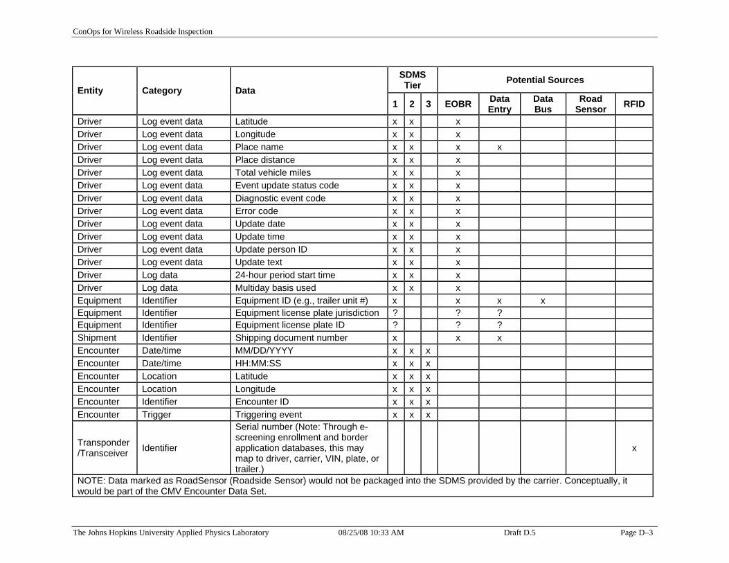
ConOps for Wireless Roadside Inspection
Entity Category Data SDMS Tier Potential Sources
1 2 3 EOBR Data Entry
Data Bus
Road Sensor RFID
Driver Log event data Latitude x x x Driver Log event data Longitude x x x Driver Log event data Place name x x x x Driver Log event data Place distance x x x Driver Log event data Total vehicle miles x x x Driver Log event data Event update status code x x x Driver Log event data Diagnostic event code x x x Driver Log event data Error code x x x Driver Log event data Update date x x x Driver Log event data Update time x x x Driver Log event data Update person ID x x x Driver Log event data Update text x x x Driver Log data 24-hour period start time x x x Driver Log data Multiday basis used x x x Equipment Identifier Equipment ID (e.g., trailer unit #) x x x x Equipment Identifier Equipment license plate jurisdiction ? ? ? Equipment Identifier Equipment license plate ID ? ? ? Shipment Identifier Shipping document number x x x Encounter Date/time MM/DD/YYYY x x x Encounter Date/time HH:MM:SS x x x Encounter Location Latitude x x x Encounter Location Longitude x x x Encounter Identifier Encounter ID x x x Encounter Trigger Triggering event x x x
Transponder /Transceiver Identifier
Serial number (Note: Through e-screening enrollment and border application databases, this may map to driver, carrier, VIN, plate, or trailer.)
x
NOTE: Data marked as RoadSensor (Roadside Sensor) would not be packaged into the SDMS provided by the carrier. Conceptually, it would be part of the CMV Encounter Data Set.
The Johns Hopkins University Applied Physics Laboratory 08/25/08 10:33 AM Draft D.5 Page D–3

ConOps for Wireless Roadside Inspection
This Page Intentionally Blank
The Johns Hopkins University Applied Physics Laboratory 08/25/08 10:33 AM Draft D.5 Page D–4