concept development by p. k. rockwell note n-1453 deep ocean cable burial concept development by p....
TRANSCRIPT

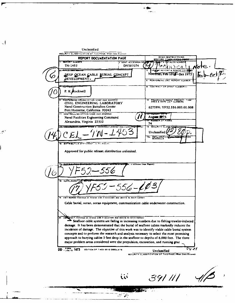
Technical Note N-1453
DEEP OCEAN CABLE BURIAL CONCEPT DEVELOPMENT
By
P. K. Rockwell
August 1976
Sponsored by
NAVAL FACILITIES ENGINEERING COMMAND
Approved for public release; distribution unlimited.
CIVIL ENGINEERING LABORATORY
Naval Construction Battalion CenterPort Hueneme, California 93043
- ---- oil
Unclassif iedSECURITY CLASSIFICATI(3N 0' THIS5 PAGE (rh-, Da-. F,-
REPORT DOCUMENTATION PAGE BFRE INSTRUCTION
T 143DN587074 0 A )1REPORT ~ ~ ~ ~ ~ ~ ~ '-A? BUSN OV CCSIO O 5CTAL & UB PER,
JLEEP QCEA' NEPORT &UIA LfRIG C
PEVEOPMET- PERFORMING ORG REPORT Nv.REIR
8 CONTRACT OR GRANT NUMSER'.?
3 -PRPORMINO ORiAIO N1", 1; 1...1. A.D.IIS% 10 PROGRAM ELEMENT PROJECT. TASK
CIVIL ENGINEERING LABORATORY AREA 6 BORK UNIT NUM8ERIs
Naval Construction Battalion Center 62759N; YF52.5 56.003.01.008
Alexandria, Virginia 22332 74 UME s
00-M00- R*WeP'WXU ADDRESS(11 dt.I~'4' I- *1 IS SECUIRITYV CLAS
La pj )..'I~(-J1-19UnclassifiedIt -I. ECLASIIEIC = RA IWO
BSUPPLCETA
It ITEV W0RDS (C-f10n.. .. . . ..It - Idi.tI1y b. bIocS .- b.,)
Cabke burial, ocean, ocean equipment, communication cable underwater construction.
aprach. Itoha brynalsfe demntaep ina the seil safloor oaepts fa,00kfet.y Teue the
major problem areas considered were the propulsion, excavation, and running gear
DO 1473 E0ITION 01 1'NOV SS IS OSSOLETE Unclassifiedr
SECURITY CLASSIFICATION OF THIS PAGE IN- Data Enterd)
JI391/Ni

UnclassifiedSECURITY CLASSIFICAION OF THIS PAGI nft5 Oat& Eut*dOM4
20. Continued
subsystems. Propulsion systems investigated included towing, thrusters, tracks or wheels,and cable traction. Excavating means included fluidizing, plowing, water jetting.trenching, and direct insertion of the cable. The running gear systems investigated wereskids, rolling elements, and a water cushion. Subsystem candidates were combined intosystem concepts, and the concepts were rated according to their power and force require-ments, probability of cable damage, capability of handling different soils and terrains,controllability, weight, size, and complexity. It was concluded that the system with thebest chance of successfully burying cables in the deep ocean while meeting the operation-al requirements and design requirements would be self-powered with thrusters, supportedon skids, and utilize vibratory plowing and/or water jetting for the burial means.
Library card
Civil Engineering LaboratoryDEEP OCEAN CABLE BURIAL CONCEPT DEVELOPMENTby P. K. RockwellTN-1453 74 pp illus August 1976 Unclassified
1. Cable burial 2. Ocean equipment I. YF52.56.003,O1.008
Seafloor cable systems are failing in increasing numbers due to fishing-trawler-inducd
damage. It has been demonstrated that the burial of seafloor cables markedly reduces theincidence of damage. The objective of this work was to identify viable cable burial systemconcepts and to perform the research and analysis necesary to select the most promising
approach to burying cables 3 feet deep in the seafloor to depths of 6,000 feet. The threemajor problem areas considered were the propulsion, excavation, and running gear subsystems.Propulsion systems investigated included towing, thrusters, tracks or wheels, and cable traction.Excavating means included fluidizing, plowing, water jetting, trenching, and direct insertion of
the cable. The running gear systems investigated were skids, rolling elements, and a watercushion. Subsystem candidates were combined into system concepts, and the concepts wererated according to their power and force requirements, probability of cable damage, capability
of handling different soils and terrains, controllability, weight, size, and complexity. It wasconcluded that the system with the best chance of successfully burying cables in the deep ocean
while meeting the operational requirements and design requirements would be self-powered withthrusters, supported on skids, and utilize vibratory plowing and/or water jetting for the burialmeans. -
UnclassifiedsECuITv CL ASSIFICATION OF Tills PHIS ,o, noe* /,,,E,
(1'

CONTENTS
Page
INTRODUCTION. .. .......................... 1
BACKGROUND. .. ........................... 1
CABLE BURIAL SYSTEM REQUIREMENTS .. ................. 5
General Operational Requirements. .. ............. 5
Specific Operational Requirements .. ............. 7
STATE-OF-THE-ART. .. ....................... 8
Trenching/Excavating. .. .............. ..... 8
Plowingo. ........................... 8
Water Jetting .. ............. ......... 10
Jet Plowing .. ............. .......... 11
Dredging. .. ............ ............ 12
Fluidizing. .. ............ ........... 12
Related Techniques. .. .................... 12
CONCEPT DEVELOPMENT. .. ............. ........ 13
SUBSYSTEM ANALYSIS .. .............. ........ 16
Excavation Subsystems. .. .................. 16
Propulsion Subsystems. .. .................. 22
Running Gear Subsystems. .. ................. 28
CONCEPT SELECTION. .. .............. ........ 32
Excavation Subsystem (Table 7) .. ... ........... 42
Propulsion Subsystem (Table 8) .. ... ........... 43
Running Gear Subsystem (Table 9) .. ... .......... 43
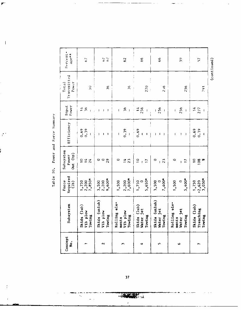
overall System Evaluation (Tables 10 and 11) .. .. ...... 43
SUMMIARY. .. ............ ................ 44
CONCLUSIONS .. .. ............... ......... 45
RECOMMENDATIONS .. .. ............... ....... 46
V
A l
Contents (continued)
Page
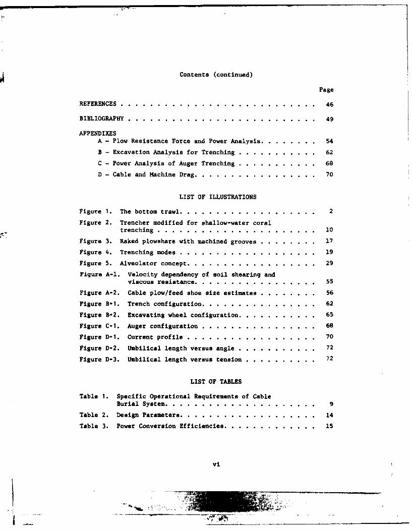
REFERENCES. .... ........................ 46
BIBLIOGRAPHY. .... ....................... 49
APPENDIXESA - Plow Resistance Force and Power Analysis. .. ....... 54
B - Excavation Analysis for Trenching .. ........... 62
C - Power Analysis of Auger Trenching .. ........... 68
D - Cable and Machine Drag. .. ................ 70
LIST OF ILLUSTRATIONS
Figure 1. The bottom trawl. .. ............... ... 2
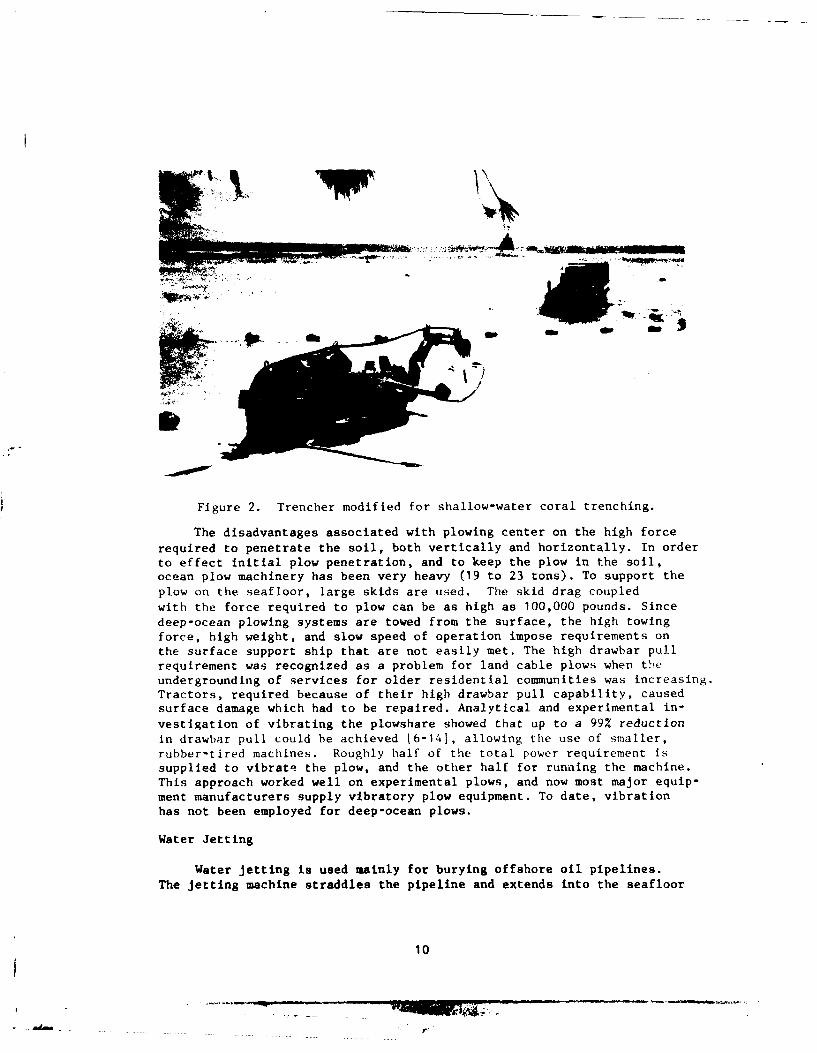
Figure 2. Trencher modified for shallow-water coraltrenching. .... ................... 10
Figure 3. Raked plowshare with machined grooves .. ........ 17
Figure 4. Trenching modes. .... ................ 19
Figure 5. Alveolator concept .. ... ............... 29
Figure A-1. Velocity dependency of soil shearing andviscous resistance .. .. ............... 55
Figure A-2. Cable plow/feed shoe size estimates .. ........ 56
Figure B-i. Trench configuration .. ... ............. 62
Figure B-2. Excavating wheel configuration. .. .......... 65
Figure C-i. Auger configuration. .. ............... 68
Figure D-i. Current profile. .... ............... 70
Figure D-2. Umbilical length versus angle .. ........... 72
Figure D-3. Umbilical length versus tension .. .. .. .. . .72
LIST OF TABLES
Table i. Specific Operational Requirements of Cable
Burial System. .. ............. ....... 9
Table 2. Design Parameters .. ... ................ 14
Table 3. Power Conversion Efficiencies. .. ............ 15
vi

JT
List of Tables (continued)
Page
Table 4. Characteristics of Three Jetting Systems ......... ... 21
Table 5. Thrust for Ducted Propellers at Zero Advance Speed . 26
Table 6. Thrust Delivered by One 4-Blade Propeller Attachedto Stern of Water-Submerged Vehicle ............. ... 27
Table 7. Excavation Subsystem ........ ................. 33
Table 8. Propulsion Subsystem ........ ................. 34
Table 9. Running Gear Subsystem ...... ................ ... 35
Table 10. Power and Force Summary ...... ................ ... 36
Table 11. Overall Rating ....... .................... ... 40
Table D-1. Vertical and Horizontal Components of T as aFunction of Cable Length ..... .............. ... 71
vii
. .. ... .... ..... . .. . .
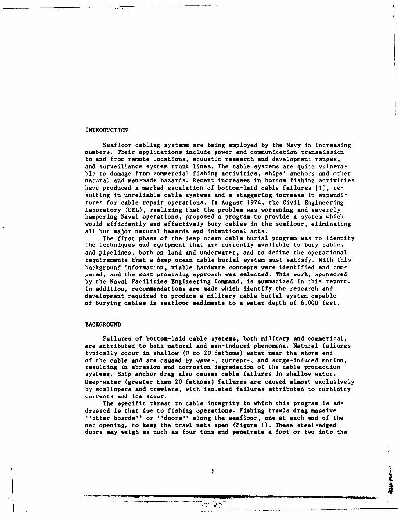
INTRODUCTION
Seafloor cabling systems are being employed by the Navy in increasingnumbers. Their applications include power and communication transmissionto and from remote locations, acoustic research and development ranges,and surveillance system trunk lines. The cable systems are quite vulnera-ble to damage from commercial fishing activities, ships' anchors and othernatural and man-made hazards. Recent increases in bottom fishing activitieshave produced a marked escalation of bottom-laid cable failures [1], re-sulting in unreliable cable systems and a staggering increase in expendi-tures for cable repair operations. In August 1974, the Civil EngineeringLaboratory (CEL), realizing that the problem was worsening and severelyhampering Naval operations, proposed a program to provide a system whichwould efficiently and effectively bury cables in the seafloor, eliminatingall but major natural hazards and intentional acts.
The first phase of the deep ocean cable burial program was to identifythe techniques and equipment that are currently available to bury cables
and pipelines, both on land and underwater, and to define the operationalrequirements that a deep ocean cable burial system must satisfy. With thisbackground information, viable hardware concepts were identified and com-pared, and the most promising approach was selected. This work, sponsoredby the Naval Facilities Engineering Command, is summarized in this report.In addition, recommendations are made which identify the research anddevelopment required to produce a military cable burial system capableof burying cables in seafloor sediments to a water depth of 6,000 feet.
BACKGROUND
Failures of bottom-laid cable systems, both military and co-mmerical,are attributed to both natural and man-induced phenomena. Natural failurestypically occur in shallow (0 to 20 fathoms) water near the shore endof the cable and are caused by wave-, current-, and surge-induced motion,resulting in abrasion and corrosion degradation of the cable protectionsystems. Ship anchor drag also causes cable failures in shallow water.Deep-water (greater than 20 fathoms) failures are caused almost exclusivelyby scallopers and trawlers, with isolated failures attributed to turbidity
currents and ice scour.The specific threat to cable integrity to which this program is ad-
dressed is that due to fishing operations. Fishing trawls drag massive''otter boards'' or ''doors" along the seafloor, one at each end of thenet opening, to keep the trawl nets open (Figure 1). These steel-edgeddoors may weigh as much as four tons and penetrate a foot or two into the
t 1

C
a
eI.
N
:3I~.4
004J4.80
.0
wIi..
9.400( rx~
I
2
iM

seafloor. When the doors encounter a cable, the cable is often snaggedand broken. No reasonable amount of armoring or mechanical protectioncan protect the cable. Since cable repairs cost in the vicinity of $300Kper repair and because the number of cable failures is increasing at arapid rate, the economic justification for reducing cable vulnerabilityis clear. In addition, the strategic and operational value of militarycable systems provides further incentive to solve this severe problem.
For the last 25 years, telephone and electric utility companieshave been burying their service lines on land to protect them fromthe elements and provide more reliable service to their customers. Asthe number of transoceanic cables increased and the incidence of damageto the cables became unacceptable, the Bell Telephone System decided thatburial of cables in the seafloor might protect these cables from damageas it did on land. In 1966, the first Sea Plow was developed. It was foundthat damage to cables buried by this and later Sea Plows was all but elim-inated. Burying cables in the seafloor effectively removes them from theprimary hazard, bottom fishing, as well as current-induced motions andanchor drag for all but deeply penetrating anchors.
The Sea Plow is a large platform, mounted on skids, with a plowshareand cable guide mechanism penetrating into the seafloor. The plow, whichis towed from the surface, is an uncomplicated piece of machinery, butit suffers from a number of deficiencies that makes it unacceptable formilitary cable installations.
Depth: The existing plow is limited to 500 fathoms. This depth wasadequate to protect cables against traditional food fishing, but overfish-ing and new markets, such as fish meal, fertilizer, and high protein animalmeal, are driving trawlers to 1,000 fathoms.
Surface Support: Only two vessels are capable of providing the supportservices required by the plow (a Canadian and a French ice breaker/cablelayer) for the following reasons:
a. The tow force required is as high as 100,000 pounds. This force,coupled with the slow burial speed (1 knot), requires large amounts ofpower, bow and stern thrusters for ship control, and a sophisticated navi-gation system.
b. The newest plow (Sea Plow IV) weighs 23 tons; thus, the ship musthave a large-capacity over-the-side handling system.
c. The plow can bury cables only while they are being laid, thus,the ship must be a cable layer, carrying large amounts of cable.
Repeater Burying: Sea Plow IV plows a 16-inch-wide ditch at alltimes so that repeaters may be buried. Since the cable requires only a4-inch-wide trench, and repeaters occur only once every 20 miles, asignificant waste of energy is associated with this operation.
Trafficability: Since the plow is mounted on skids, obstacles,such as rocks, often cause the device to stall, and it must be recoveredand the operation restarted. Some cable, then, is left unburied.
3

PZow Insertion: Difficulties in inserting the plow in the seafloor
require about 1 nautical mile (nm) before the plow is fully engaged. Thecable is left partially buried in the interim.
Availability: Because the plow relies on one or two ships for opera-tion (the French ship may not be capable of supporting Sea Plow IV), andbecause the plow is owned by private industry, the cable plowing systemis not readily available to the military.
The only other method Lnat has been used to bury cables in the
deep ocean is water jetting. Repeaters that had not been buried by theSea Plow were jetted into the sediment. In one case a jet pump was held
by a submersible manipulator 12), and in the other case a specially de-signed jet fixture was mounted on the end of a drill string [3]. Bothattempts were successful, but this type of operation is very slow (and,therefore, not suitable for burying hundreds of miles of cable), expensive,and has been accomplished only in sandy bottoms. In addition, submersibleoperations of this type are quite dangerous. The drill string mountedjetting device is limited to about 600 feet because the string excursionbecomes too great to control.
It is clear, then, that the Navy requires an improved means of bury-ing deep-ocean cable installations in the seafloor. The approach takento complete the first phase of this program, and reported here, is thefollowing.
1. Establish the operational requirements that the improved cableburial system must meet, such as burial depth, water depth, soil type,available surface support, and characteristics of present and future cableinstallations which must be protected.
2. Analyze existing techniques for burying cables (and pipelines)underwater and on land, identifying methods that are applicable to thedeep-ocean cable burial problem at hand.
3. Define deep-ocean burial system concepts that utilize feasibleburying means previously identified. Consider various methods of self-propulsion, and compare these with a passive (towed) system.
4. Specify, quantify where possible, and analyze the system concepts,taking into account their capabilities vis a via established operationalrequirements, physical embodiment, power requirements and efficiency,problem areas requiring preliminary research or development, engineeringand technical difficulties, shipboard requirements, and probability ofsuccess.
5. Select the most promising concept or concepts, and establishdevelopment plans necessary to bring the conceptual system to theexperimental hardware stage.
While it has been demonstrated that burying a cable provides an ex-cellent measure of protection against fishing activities, it is clearthat not all cable failures can be avoided. Failure of a buried cablepresents several problems unique to buried cables; that is, how is the
4

cable found, and how is access gained to the cable to effect a repair.
Also, once the cable is repaired, how is it buried again. The first twoitems, location and repair, are not intrinsically part of a cable burialsystem, and would unnecessarily complicate the hardware and threaten thesuccess of the development program. Therefore, location and repair ofa buried cable are not imposed as requirements of the cable burial system.Also, the telecommunication industry is currently developing a systemto locate and repair buried cables. Since failure of buried cables willbe an unlikely event, the repair system will be rarely used, and, there-
fore, should be available to the Navy on a contractual basis as needed.Burying the cable after a repair is made will be within the capabilities
of the cable burial system, as it is foreseen that cables which must beburied may already have been repaired one or more times. Burial of a repairsection is also within the capabilities of the cable repair system beingdeveloped.
CABLE BURIAL SYSTEM REQUIREMENTS
To develop a cable burial system that will provide adequate protectionto Naval cable installations, a set of operational requirements must beidentified and ranked in their order of importance. The requirements iden-tified below are divided into general operational requirements and specificrequirements. The general requirements are the more important ones, andimpact heavily on the selection of a good concept. Specific requirements
affect subsystem capabilities which must be part of any of the concepts.
General Operational Requirements
a. Bury cable no less than 3 feet in the seafloor without damagingthe cable.
This requirement, the most important, is the basic objective of theentire program. A cable burial mission analysis [1] determined that damage
due to fishing activities will be eliminated if the cable is buried 3feet deep in water depths greater than 20 fathoms. Obviously this mustbe accomplished without damaging the cable. The mission analysis also
determined that a 6-foot burial depth is required in water depths from5 to 20 fathoms, principally due to the anchor drag threat. Although itis important to meet this shallow-water requirement, it is felt that the
increased burial depth has little impact on concept selection. Also, itmay be more effective to use nearshore cable burial techniques that arebeing developed separately to depths of 20 fathoms.
b. The cable burial operation must be supported from a ship ofopportunity.
The Bell Sea Plow buries cable during a cable-laying operation,weighs 23 tons, and requires a nominal tow force of 50,000 pounds at aspeed of 1 knot. Use of a ship of opportunity, although ranked second
5Ml I

in importance, has the furthest reaching effect on the burial system
concepts. Because available ships have limited weight-handling and thrustcapabilities, a smaller, lighter-weight system is required. Force reduction
techniques and/or elimination of towing for propulsion will be necessary.The burial system must be capable of burying previously laid cables sincethe support ship will not necessarily be a cable layer. Surface supportsystems must be modularized and self-contained such that they can be read-ily installed on a variety of ships. A deck-handling system and portablepower generation system must be supplied. The importance of not damagingthe buried cable increases, as the support ship may not have a cable repaircapability. Many specific requirements, discussed later, result from thisgeneral operating requirement.
c. The system must bury cable in all seafloor soils except rock andcoral.
Most deep-ocean cable routes occur on sand, silt, or clay bottoms.
Because of the areal variability of soil type and the difficulty ofchanging to different burial systems in mid-operation, the selected burial
system must be capable of operating in all seafloor soils. Bottom-trawlingtechniques cannot be used in rocky areas; therefore, cable burial in rockis not required. Nearshore rock and coral cable route installations arebeing developed separately.
d. The burial machine power requirement must not exceed 500 hp.
Although this value is somewhat arbitrary, this power level iswithin current capabilities of power generation, distribution, and cable
and connector technology. If the power load is much higher than 500 hp,a higher frequency distribution system would be desirable to save trans-former weight [4]. This would require non-standard components which would
adversely affect the simplicity and reliability of the system. Highervoltage levels could be used to reduce the conductor size, but cable andconnector insulation would present problems. Also, a higher power levelwould require a larger power generation system which impacts on the shipsupport requirement discussed earlier.
e. The cable burier must be capable of avoiding minor obstacles.
This requirement is essential to the integrity of the burying machine
and of the cable. Minor obstacles include glacial erratics (bouldersdeposited by melting glaciers), debris, small rocky areas, reefs, ordepressions. An obstacle detection system will be required, that can feedinformation to the burier control system. Large obstacles, such as exten-sive rocky areas, ridges or valleys, will have to be avoided by employing
carefully selected and investigated cable routes.
f. Repeaters must be buried.
Repeaters occur only occasionally, and, if they were left unburied,
a large measure of protection would still be afforded to the cable system.
6
r €.

However, the importance of the cable system, the expense of repairs, and
the increase in fishing operations all dictate that as much of the cablebe buried as possible, including repeaters.
g. The system must be simple and reliable.
This requirement is at odds with most of the others, which implya high degree of sophistication and complexity. In essence, this require-ment constrains the selection of exotic techniques which oversolve theproblem at the expense of a complex system prone to nuisance breakdowns.
Certainly, the cable burial system will have to be sufficiently sophisti-cated to perform well in a rather trying environment.
An implication of this requirement is that the effort should leantoward engineering development to extend and improve existing technology,rather than to perform basic research to validate ''blue sky" ideas.
Specific Operational Requirements
a. The system must bury previously laid cable.
This requirement results from operating with ships of opportunitybut is also important for other reasons. A cable-laying ship operatesat speeds to 8 knots, while a cable-burying operation proceeds at about1 knot. If the burier can bury cables only while they are being laid, the
cable-laying operation is inefficient, and the probability of the layingoperation being interrupted by adverse weather increases. Obstacles,breakdowns, and deteriorating weather can be handled more easily if thetwo operations are not being carried out at the same time. Burying pre-viously laid cables will allow unburied cable systems which are in currentuse to be protected by the burial system.
Certain operational advantages result from a two-step operation aswell. For the installation of a high priority cable system, the cablelaying could proceed at 8 knots, and the system be made operational. The
cable could then be buried at a later date without having delayed thecable system's use.
Finally, the burial system's capability to pick up and drop a cable,implied by this requirement, allows rapid abandonment of the burial oper-ation if the weather worsens, eliminates the necessity of deploying andretrieving the burial system with the cable threaded through the machine,and allows burial of repair sections.
b. The burier must be able to track the cable.
Previously laid cables are not necessarily straight, so the buryingmachine must sense changes in cable direction. The sensor must provideinformation to the machine's control system and/or the support ship toavoid damaging the cable or overturning the machine.
c. The system must be able to bury spliced repair sections of cable.
Even if a cable has not been in place for a long time, it may havebeen damaged and repaired prior to burial. Older cables almost certainly
7
- _. -- ' - _ iI , J , .. . . .
Ad

will have been repaired. A means of burying these slack sections of cable,
whether it be the primary burial means or a subsystem, must be provided.
d. Additional specific requirements as developed in Reference I are
shown in Table 1.
STATE-OF-THE-ART
Cables and pipelines have been buried on land and under waterwyvs
for many years and lately in ocean bottoms. This section discusses tie'
variety of techniques used to accomplish burial tasks, examines theiradvantages and disadvantages, and, where applicable, references burial
systems using these techniques underwater.
Trenching/Excavating
Trenching and excavating are the most common methods used for install-ing buried cables and pipelines. Typical equipment used includes backhoes,
chain/bucket trenchers, and excavating wheels. In the mid-1960s, a Belgianfirm modified an excavating wheel trencher to bury 600 feet of power cableat depths to 40 feet in the river Scheldt [5]. The trencher was capable
of excavating a 5-foot-deep, 20-inch-wide trench at a rate of 150 ft/hr.About the same time, a conventional backhoe was modified for underwater
use that could excavate 200 feet of 4-foot-deep trench, 18 inches wide,
in a day. Recently, a commercial cutter wheel trencher was modified and
used in 120 feet of water to trench cable in sandstone. CEL recently useda similar trencher in coral (Figure 2).
Trenchers such as these are attractive in that they can be used in
material as hard as granite. Wheel and chain/bucket trenchers can beequipped with cable feed mechanisms that allow placing the cable while the
trench is being excavated. Backhoes require a three-step operation - trench-
ing, placing the cable, and backfilling. In soft or sandy materials, a
means to keep the trench from slumping in must be provided until the cable
is installed. The major drawback for the trenching/excavating techniqueis that it is an inherently slow process. Supply power, usuailv in chrc50-to-150-hp range, is well within the range considered feasible for deep-ocean cable burial.
Plowing
Plowing in cables and small-diameter pipelines was developed princi-
pally to increase the efficiency of installation. The cable can be in-stalled through a feedshoe that immediately follows the plowshare. Little
or no surface restoration is required since very little earth is forcedout of the slot. Plowing cables has been proven feasible for deep-ocean
cable burial by the Sea Plow (discussed in the Introduction) and by two
Japanese firms that have developed plows. Repeater handling has been accom-modated by lowering auxiliary plowshares to widen the ditch, or by plowing
a repeater-sized ditch over the entire cable route. The hardware requiredfor plowing cables is relatively simple, a particularly attractive feature
for deep-ocean application.
8
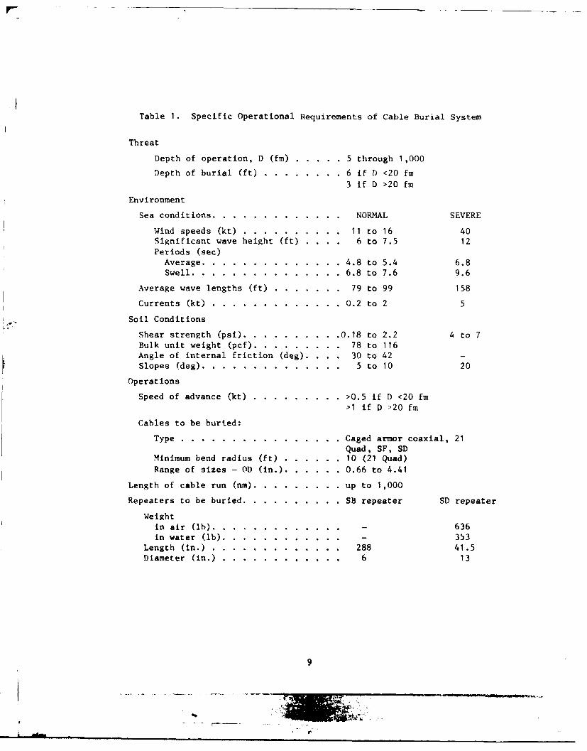
Table 1. Specific Operational Requirements of Cable Burial System
Threat
Depth of operation, D (fm) ...... .. 5 through 1,000
Depth of burial (ft) .......... .. 6 if D <20 fm3 if D >20 fm
Environment
Sea conditions .... ............. ... NORMAL SEVERE
Wind speeds (kt) ..... .......... 11 to 16 40Significant wave height (ft) .... 6 to 7.5 12Periods (sec)Average ..... .............. .4.8 to 5.4 6.8Swell ..... ............... .. 6.8 to 7.6 9.6
Average wave lengths (ft) ........ ... 79 to 99 158
Currents (kt) .... ............. .. 0.2 to 2
Soil Conditions
Shear strength (psi) ............. .0.18 to 2.2 4 to 7Bulk unit weight (pcf) ........... ... 78 to 116Angle of internal friction (deg). . . . 30 to 42 -Slopes (deg) ..... .............. ... 5 to 10 20
Operations
Speed of advance (kt) .. ......... .. >0.5 if D <20 fm>1 if D >20 fm
Cables to be burted:
Type ...... ................ ..Caged armor coaxial, 21Quad, SF, SD
Minimum bend radius (ft) ........ ..10 (21 Quad)Range of sizes - OD (in.) ........ .. 0.66 to 4.41
Length of cable run (nm) ............ .up to 1,000
Repeaters to be buried ............. .SB repeater SD repeater
Weightin air (lb) ............... - 636in water (lb) ............ - 353
Length (in.) .... ............. ... 288 41.5Diameter (in.) ... ............ ... 6 13
9
4~-
Figure 2. Trencher modified for shallow-water coral trenching.
The disadvantages associated with plowing center on the high force
required to penetrate the soil, both vertically and horizontally. In orderto effect initial plow penetration, and to keep the plow in the soil,ocean plow machinery has been very heavy (19 to 23 tons). To support theplow on the seafloor, large skids are used. The skid drag coupledwith the force required to plow can be as high as 100,000 pounds. Since
deep-ocean plowing systems are towed from the surface, the high towingforce, high weight, and slow speed of operation impose requirements onthe surface support ship that are not easily met. The high drawbar pullrequirement was recognized as a problem for land cable plows when tieundergrounding of services for older residential communities was increasing.Tractors, required because of their high drawbar pull capability, causedsurface damage which had to be repaired. Analytical and experimental in-vestigation of vibrating the plowshare showed that up to a 99% reductionin drawbar pull could be achieved [6-141, allowing the use of smaller,
rubber-tired machines. Roughly half of the total power requirement issupplied to vibrate the plow, and the other half for running the machine.This approach worked well on experimental plows, and now most major equip-ment manufacturers supply vibratory plow equipment. To date, vibrationhas not been employed for deep-ocean plows.
Water Jetting
Water Jetting is used mainly for burying offshore oil pipelines.
The Jetting machine straddles the pipeline and extends into the seafloor
10
SAma

to the desired depth of burial. Water or an air-water mixture is suppliedto the machine from the surface. These Pystems are generally high-flow,medium-pressure systems (20,000 to J0,0LA qpw at 1 000 to 2,500 psi) thatare towed along the pipeline [15]. The jt-, bzcak tp the soil, andthen air or water eductors lift the soil/water miytzre out of the trench.The pipeline settles into the trench after 1.ae mach4 ne passes, and naturalaction eventually backfills the trench. The m in disadvantage to jettinga trench for the cable to settle in is the large amounts of power required.Comparing four operational pipeline jetting systems working at capacity,the average power supplied per unit excavation rate is [17,18,19,16]:
11.6 hp*PD 3avg ft 3/mn
Using this power-excavation rate density figure for a deep-ocean cable
burial system would require over 1,000 hp. These systems normally operateat 5 to 30 ft/min (1 kt - 101 ft/mn) and work best when guided by a stiffpipeline. They also are constrained to work in a relatively firm soil sothat the excavation will not fill in before the pipeline settles into place.
Analytical studies for pure jetting (i.e., where no equipment pene-trates the seafloor) have shown that the power-excavation rate densitycan be as low as 0.4 hp/ft 3/min [20]. Using this figure, 40 hydraulichorsepower would have to be supplied to jet a 3-foot-deep, 4-inch-wide
trench at a speed of 1 knot. No information was encountered which discussedthe effect of depth of cut and speed of advance on power requirements.Pure jetting is a simple technique that has been used with some successby the Pisces Submersible and the Alcoa Seaprobe. Disadvantages of purejetting are that (1) the amount of material which must be excavated dependson the angle of repose of the soil, (2) there is no positive means of en-
suring the desired burial depth, and (3) backfill depends on re-sedimentation of the excavated soil.
Jet Plowing
As the name implies, jet plowing combines the features of both water-jetting and conventional plowing. This technique has been used quitesuccessfully by the Harmstorf Hydro jet and Aquatech cable plow forshallow water and river crossing [17-25]. In essence, the water jetsloosen the soil in front of the plowshare, reducing the frontal resistanceon the plowshare. The soil is kept in suspension until the plowshare andcable guide pass, whereupon it settles. Very little soil is actually remov-
ed from the ditch, and no backfill is required. The Harmstorf unit isequipped with a vibration means to help break up competent soil. Jet plowsare usually pulled with winches from a barge or from shore. Total powerrequired ranges up to 1,500 hp. These systems historically have requiredsupervision and inspection by divers, which is not to say they cannotbe redesigned to operate without first-hand supervision.
• In Reference 26, this function is referred to as Nominal Overall
Specific Energy /n lb
11
in.3
__M

Dredging
Dredging, which combines a rotating cutting head and suction pumpfor spoil removal, is a very effective means of removing soil. Two similardevices, the Mole [27] and the Gopher [28], are pipeline machines thatstraddle the pipe and have mechanical cutters on each side of the pipeangled towards each other. The cutters dislodge the soil which is thenremoved by a suction dredge pump. The Gopher also has water jets and air-lift pipes to help remove the spoil. The most technically advanced dredgingsystem for burying pipelines is currently under development by Tecnomare(Italy) [29]. It is a tracked crawler machine with two dredge cuttersmounted on articulated arms. The system may be programmed to dredge aprearranged path, or it may be manually controlled from the surface. Dredgespoil is pumped to the rear of the machine to bury the pipeline afterit has settled in the trench. The system can be made neutrally buoyantand is supplied from the surface with 1,300 hp. Dredging is a proven under-water excavation technique, but generally requires large amounts ofpower, excavates more soil than necessary for burying a cable, is slow,and does not lend itself well to backfilling.
Fluidizing
Fluidizing is a technique where water is pumped into the soil atsuch a rate that as it flows out of the soil, the individual soil particlesare buoyed up by the water. The soil/water mixture achieves a fluidor "quick'' condition which will not support applied shear forces.
Shell Laboratories (The Netherlands) has developed a fluidizing systemfor burying pipelines [30]. The soil is fluidized under a predetermined saglength, and the weight of the pipe and fluidizing device causes thepipeline to ''sink'' into the fluidized soil. This technique works insandy (noncohesive) soil, but to date it has been stymied by cohesive(clay) soils as the intergranular forces cannot be overcome and thesoil will not fluidize.
Related Techniques
Other techniques which have been used or proposed for burying cablesand pipelines include cavitation cutting, high-pressure water jetting,directional drilling, and piercing tools.
Cavitation cutting is basically a forced erosion process that dependson the formation and violent collapse of bubbles in a fluid. The cavitationerosion is caused by the shock wave produced when the bubble collapses,and the energy density is sufficient to erode materials such as rockand metal. The intensity of the cavitation, and, therefore, the penetrationrate, increases with hydrostatic pressures [31]. Cavitation cuttingdevelopment is still in its infancy, and acoustic transducers powerfulenough to produce the necessary threshold energy levels for high ambientpressures have not been developed. This technique produces localizedenergy densities effective for drilling through rock.
12

High-pressure water jetting, or ''water cannon,'' is a technique that
has particular application for fracturing rock. To generate high pressures,a rapidly moving piston impacts on a slug of water and extrudes it through
a nozzle, producing a very high velocity water impulse. The water impulsejet of a prototype underwater unit used for cleaning scale from steel is
about 1/2 cm in diameter, and the device requires 250 hp [321. The applica-tion of high-pressure water jetting or cavitation cutting for high-volumeexcavation in soft materials has not been reported.
Directional drilling is a technique reported on by Valent [33] for
installing the nearshore end of a cable system. Its attractive featureis that a shore-based drilling rig can drill under the surfzone and rockyareas to a distance offshore where nearshore effects have dissipated.Piercing tools, such as the Pneuma Gopher, have been developed to dig
their way from one point to another when trenching is undesirable, suchas under a busy highway. Both of these techniques are suitable for producinga relatively short path through which cabling can be led after the hole is
made.
CONCEPT DEVELOPMENT
The major problem areas associated with existing ocean cable burialsystems are the machine/soil interface, and the machine/surface supportcontrol and propulsion interface. These problem areas are quite closelyrelated; for example, the large forces experienced in the machine/soilinterface cause problems in propulsion and control for the support ship.To approach a solution to these general problem areas, three major catego-ries were analyzed, and the resulting information combined in variousways to formulate concepts. These categories are:
1. Excavation Subsystem
2. Propulsion Subsystem
3. Running Gear Subsystem
To provide a common basis for comparision of the various techniquesof burying cables, a set of parameters was selected from the specificoperational requirements which represent maximum normal operating condi-tions. Each concept was analyzed to determine the power required andthe resistance force produced by operating under these conditions. Maximumallowable target values for size, weight, and force required were alsoassigned as they must be used for some of the power and force calculations.The values are shown in Table 2, and power conversion efficencies areshown in Table 3.
The burial machine weight and size were selected as desirable maximumvalues to allow convenient handling from ships of opportunity. The sizeaffects water drag on the system and bottom stability. Machine weightimpacts on the running gear/soil interface forces and allowable groundpressure. The machine speed and current profile create a drag force on the
13

umbilical cable, which is at maximum when the current profile adds to
the system speed at maximum operating depth. The trench dimension istypical for most of the burying operations. The system must slow downor consume more power for repeater burial or deeper burial. Finally,the soil characteristics have a large impact on power and force. Fortougher materials, the system must slow down or consume more power, andfor weaker soils the speed can be increased or the power reduced.
Several excavation techniques that have been used or suggested forburial of objects in the seafloor are inappropriate for deep-ocean cableburial because of their inability to meet some of the basic operatingrequirements. Therefore, they could be eliminated without performing adetailed power analysis.
Fluidixation. The fluidization process is not applicable since it is
intended for cohesionless materials (i.e., sands) and depends on the ab-sence of intergranular attractive forces for successful operation. Recenttests with Shell's fluidizer showed that the system stalls when clayis encountered [34). Many of the seafloor soils which will be encountered
are cohesive, and switching burial equipment in mid-operation is notan acceptable solution to the deep-ocean cable burial problem.
BZaeting. Blasting is not an appropriate method of burying long cable
runs in sand and clay since it is best used for fracturable materials suchas rock and coral, is a batch (rather than continous) process, and todate, requires divers to prepare blast holes and set the charges.
Table 2. Design Parameters
Burial machine weight ... .......... .10 tn (max)Burial machine size envelope ......... .. 12 ft wide x 25 ft long
x 10 ft tall (max)
Motion resistance force .. ......... .. 5 tn (max)Power ....... .................. .. 500 hp (max)Speed ....... .................. .. 1 kt (101 ft/min)
Current ......... ................ 2 kt at surface
0 at 300 ft
Trench dimensions .... ............ .36 in. deep x 4 in. wide
Umbilical cable .... ............. .. 3-in. diameter6,500 ft long
Soil characteristics ... ........... .Clay
Undrained shear strength,S - 4 psiuBulk density,
p - 100 lb/ft 3
14

Input
ductedhydralicl hyrauli
0.15 0.69 piston
mootor
0.0.
0.97 crnse 0.97
Table 3. Power Conversion Efficiencies 1
0.08 0.39
Cavitation Cutting and ?Hgh-Pre , e-e Jetting. Both of these techniquesuse the principle of focusing moderate amounts of energy to achieve ultra-high energy densities to cut, fracture, or erode materials such as rockand metal. As such, they are not suitable means of excavating a trenchin soft materials. High-energy density water jets achieve 100,000 to5,000,000 psi in a jet 1/16 inch in diameter. The optimal cutting rangeis 20 nozzle diameters, and the jet pressure should be at least 10 timesthe material strength [351. Extrapolating this information to digginga 3-foot-deep trench in a typical (4-psi) seafloor soil suggests a nozzlesize of 1-1/2 inch and jet pressure of 40 psi (minimum). Thus, it canbe seen that the high-pressure water Jetting technique provides nominally2,500 times the pressure required to cut seafloor soil, and the jetsare so small that only a localized area of soil would be excavated. Extra-polation of high-pressure water jet theory to soil excavation leads tostandard (low-pressure) Jetting techniques. Cavitation cutting resultsin pressures and cutting volumes similar to high-pressure water Jetting.
Direct Insertion. Using this method, the cable is simply forced intothe soil with, for example, a heavy wheel. The wheel must be forced throughthe soil while penetrating 3 feet into the bottom. Preliminary analysisshowed that, even if the wheel were water lubricated such that an 80%reduction in frictional resistance could be attained, the forward forcerequired to push the wheel through the soil ranges from 4,400 pounds fora 4-inch-thick wheel to 7,900 pounds for a 16-inch-thick wheel. In addition,
15

the force on the wheel required to achieve 3 feet of penetration rangesfrom 7,000 pounds to 28,000 pounds. This approach was eliminated becausefull penetration is not assured, tracking the cable Is a difficult process,and the probability of damaging the cable is very high since the cablecould be forced into a rock or other hard surface.
SUBSYSTEM ANALYSIS
The following sections present force and power analyses and discussthe subsystem candidates which appear to be most appropriate for a deep-ocean cable burial system.
Excavation Subsystems
Plowing. Plowing cables into the soil is a relatively simple andquite efe-ctive means of burying cables. Plowing has been used extensivelyand very successfully on land and has had some success underwater. Thebasic problems with cable plowing are the high force required to move theplow through the soils (drawbar force) and the force required to achieve andmaintain plow penetration. Appendix A and Reference 36 discuss drawbarforce predictions for a plowshare.
Appendix A shows that the total drawbar force required to move aplowshare through the soil is larger for clay than for sand, and isvelocity dependent.
F C F + FTOT v s I
where FTOT total resistance
C v a velocity coefficient determined from Figure A-iv
F W force due to static soil resistance
s S u As u NCA fF an inertial term
(1/2)ps Af CD v2
S - undrained shear strengthu
A - side area of plows
A f frontal area of plow
N - dimensionless coefficient a 10
PS soil mass density
CD drag coefficient a 1.5
v W velocity
16
we.,

To guide the cable to the bottom of the 3-foot ditch without exceedinga minimum bend radius of 5 feet, the feedshoe/plow length must be 10feet (Figure A-2). Using the design parameters discussed previously,the total force required to pull the plowshare at a speed of 1 knot isFT_ = 44,000 pound. This formulation for predicting drawbar pull comparesTOTfavorably with results published for Sea Plow llI 1371.
References 8 through 14 present analytical and experimental resultsof using plowshare vibration to reduce the drawbar force required to movethe plowshare through the soil. In particular [13], it has been shown thatfor vibratory plowing, the use of a raked, wedge-shaped blade with machinedgrooves (Figure 3) reduced the average horizontal plowing force in a siltysand by 98 to 99% when the plowshare was vibrated at a frequency of 20 to40 Hertz at an amplitude of 3/8 inch. In addition, vibrating the plowshareaids in achieving and maintaining depth of penetration. In the case above,a 95% reduction in drawbar force gives
FTOT reduced - 2,200 lb
which is well within the target requirement of 10,000 pounds. (Note:
Other contributions to drawbar force will be discussed later.) This reduc-tion in drawbar force will impact significantly on the support ship powerrequirements for towing, and ease control problems.
The power required to vibrate the plowshare is also an importantconsideration. Appendix A shows that the power required to produce vibra-tions is 14 hp. Water drag and added mass effects on the power requiredfor vibration are negligible. To move the vibrating plowshare at 1 knot:
200Figure 3. Raked plowshare with
machined grooves.
17
7

P - F v - (2,200 lb) (1.69 ft/sec) = 7 hp
PTotal - 21 hp
Without vibration,
Ptotal - F v = (44,000 lb) (1.69 ft/sec) = 135 hp
So in addition to a significant decrease in drawbar force, vibrating
the plowshare also results in a reduction in net power requirements.
Trenching. Two types of trenchers are considered, the endlesschain-bucket trencher and the cutter wheel trencher. Both types oftrenchers normally rotate such that the cutting action is in the directionof machine travel (upmilling) (Figure 4). The machine, then, must supplysufficient drawbar force to overcome the cutting resistance. If, however,the trenching means rotates in the opposite direction (climbmilling),cutting resistance acts to push the machine forward, and to lift thedevice out of the trench. Appendix B presents a force and power analysisof both chain and wheel trenchers.
For a wheel trencher or chain trencher, the bucket comes in contactwith the soil and, when forced through the soil, fails it in a mannersimilar to the plowshare discussed previously. The total force requiredto cut the soil is
Su AsFTOT -S Af Nc + 2
where the first term represents the soil bearing resistance force, andthe second a shearing resistance force [381. Nc in this case is a dimen-sionless factor 1 3 because of free surface effects.
For a chain-bucket-type trencher with the boom angled 60 degreesbelow horizontal the analysis in Appendix B shows that the maximum powerrequired to excavate a 4-inch-wide, 36-inch-deep trench at 1 knot is
P m 108 hpmax
For upmilling the forces on the unit are
Fup M -2,675 lb
FM - -2,620 lb
With the system operating in the opposite direction (climbmilling), theforces are
Fup M 2,560 lb
FFWD - 2,620 lb
18

'44i . o .'. i
(a) Upmilling. (b) Climbmilling.
A. Chain Bucket Trencher.
C.. 0j 0>
(a) Upmilling. (b) Cimbmilling.
B. Wheel Trencher.
Figure 4. Trenching modes.
19
df-
and the power requirement is the same. For the cutting wheel trencher,a parallel analysis results in
Pmax - 94 hp
For upmilling
F UP - - 3,515 lb
FFWD - -4,430 lb
and for climbmilling
P - 94 hpmax
F up 3,350 lb
F - 4,430 lbFWD
Climbmilling appears attractive in that, for the same power as upmilling,a drawbar assist of 2,600 to 4,400 pounds is available to overcome therunning gear/soil interaction forces, cable drag, and water drag on themachine. The machine must weigh greater than the upward force to keep thetrencher from digging itself out of the trench. However, the incidence ofstiff clays or rocks may cause the cutting wheel or trencher to climb outof the trench, resulting in instability of the machine and possibledamage to the machine and the cable. Shock absorbing, braking, and possiblyother control systems must be incorporated into the trencher. It may alsobe necessary to direct a water stream on the buckets to loosen and removetrenched soil.
For upmilling, the system can be very light (neutral if desired)since the cutting force provides a significant downward force, but themachine must provide 2,600 to 4,400 pounds of drawbar force in additionto the other forces acting against the system's forward progress. Powerrequirements in both cases are high due to the high digging rate requiredfor a 1-knot speed of advane.
Water Jetting. Although water jet excavation is the most comnmon
means employed for pipeline burial, very little analytical or experimentalinformation was encountered in the literature. References 39 and 40discuss research performed on Jetting in sand. The trench depth is relatedto the jet flow parameters by
d 3 - C1 Q(P + C2)1 /2
20
'A U

where d = trench depth
Q = flow rate
p = jet water pressure
C, = constant determined by grain size
C2 = constant determined by distance from jet to seabed surface
It can be seen that the excavation depth increases more rapidlv witliincreasing flow rate than with increasing pressures. If the hydraulicpower, P = Q p, is kept constant, increasing the flow rate will produce adeeper trench than increasing the pressure. Also, the trench depth
decreases as the speed of the jet across the seafloor increases. Toestimate the power required to jet a ditch into the seafloor, the powerand performance of two pipeline jetting devices and a planned cablejetting device were used to calculate a power density function, defined as
SDelivered Power (hp)
Soil Excavation Rate (ft3 /min)
Table 4 is a surmnary of the jetting systems' characteristics and resultantpower densities. The variation in power densities for the three systemsis not readily explained, but may be the result of several factors:
System 3 is still on the drawing board andmay be underpowered.
Systems 1 and 2 may be excavating more soilthan the nominal trench dimensions.
Systems 1 and 2 may be supplying more power
than is required to do the job.
Table 4. Characteristics of Three Jetting Systems
Characteristic System 1 [41] System 2 [16,42] System 3 [20]
Trench depth (ft) 12 7 1.2Trench width (ft) 9 9 2
Trench shape rectangular rectangular triangularSpeed (ft/min) 3.3 47 50Flow (gpm) 36,000 16,000 300Pressure (psi) 28 1,750 125PD (hp/ft3 /min) 1.7 5.5 0.4
21
.4"
The average value of these three systems is taken as an estimate for the
power density function for burying cables. To jet a 4-inch-wide, 36-inch-deep trench at a speed of 1 knot, the soil excavation rate is 101ft3 /min. Using PDavg - 2.5 hp/ft 3/min, the total power required is 256 hp.
Auger TrenchinA. Auger trenching and cutter head dredging arebasically very similar mechanisms in that a rotating surface fails thesoil. The basic difference is that augers physically remove the spoilwhere dredges crumb the soil and a dredge pump removes the spoil. A dredge
cutter head is basically spherical which requires that the trench depthequal the trench width on a single pass. Thus, to attain a 3-foot-deeptrench, the trench must be 3 feet wide. Since the trench need only be4 inches wide, more work than necessary is being done, which leads tohigher power requirements.
Double vertical counter-rotating augers have been used with somesuccess for burying pipelines. Very little information was available inthe literature, so a power analysis parallel to that for trenching wasperformed (Appendix C). The power level for one 4-inch-diameter augerwas 75 hp, somewhat higher than for vibratory plowing and about the sameas for trenching. The soil removal rate, however, requires an auger speedof 5,000 rpm. This high rotary speed required by the soil removal rateassociated with a 1-knot speed of advance appears unrealistic for soilcutting. Encountering a rock or other unyielding surface at that speedwould most likely damage the auger considerably. The force necessary tomove counter-rotating augers through the soil is expected to be near thatfor vibratory upward soil cutting (2,200 pounds) in that the soil is being
lifted and failed at a rapid rate.
Propulsion Subsystems
Towing. Virtually all of the cable and pipeline burial systemsrely on towing as their primary means of propulsion. Most use thekedging anchor technique with power winches on the support barge. Sincethis process is slow and may necessitate stopping while anchors are reset,it is not suitable for deep-ocean cable burial. The Bell and Japanesecable plows are towed from a ship, which lays cable simultaneously. Forthe Bell system, 2,000 shp is required to tow with an average tensionof 33,000 pounds at an average speed of 1 km/hr [37]. Taking the ratio ofthe delivered power to the supplied power results in the overallefficiency (exclusive of the prime mover)
Pdel, (33,000 lb) (0.911 ft/sec) hp
P sup 2,000 hp 550 ft-lb/sec
noverall - 0.06
22
Of the total tension supplied, 2/3 goes into plowing and 1/3 is used
to overcome other drag forces. The supplied power for plowing, on theaverage, is 36 hp. While towing is highly inefficient from a powerstandpoint, it is not meaningful to compare other propulsion systemefficiencies with that for towing, because the power is presumablyalready available on the support ship.
Towing is the simplest propulsion system resulting in the leastcomplicated machine control system and requiring no electrical powertransmission. Towing has a number of drawbacks, however.
1. Ship of opportunity navigation systems are not sufficientlyaccurate to allow burying previously laid cables without picking up thecable and leading it back to the machine. Burying cables while layingrequires the use of a cable-laying ship.
2. Cable-laying ships generally operate at 5 to 8 knots, and plowing-while-laying averages about 1/2 knot due to ship thrust limitations.This mismatch makes the laying operation inefficient, and makes thelaying/burying operation more vulnerable to adverse weather conditions.
3. Supplying propulsion from a surface ship forces the buryingmachine to move at ship speed, regardless of bottom conditions. Thus,quick response ship control is required to avoid breaking the tow cable
or damaging the burying machine.
4. Handling three cables from the support ship - umbilical, towcable, communication (buried) cable - presents a substantial entanglementproblem.
5. A ship of opportunity has no fine control over the path of themachine - the machine must simply follow the ship.
6. Supplying large towing forces at slow speeds makes ship controldifficult. Sideways thrust control is essential. Utilizing force reductiontechniques will reduce the severity of some of these problems, but theship/machine control problem will remain.
Track/Wheel Propulsion. Tracked and wheeled vehicle mobility has beendeveloped extensively for all types of terrain except ocean bottoms. Theonly vehicle of consequence to traffic the seafloor is the RUM vehicle,a converted land-based tracked vehicle. At that, RUM was not called uponto provide large drawbar forces, and its weight on the seafloor is oftencontrolled from the surface. Underwater bulldozers developed in Japan havebeen reported in trade journals recently, but no performance information
has been available.The basic iechanism for determining the drawbar force, or tractive
effort, developed by a tracked or wheeled vehicle is based upon Coulomb'stheory:
F - W tan + A c
23
*.~ ~.sB. .s..*
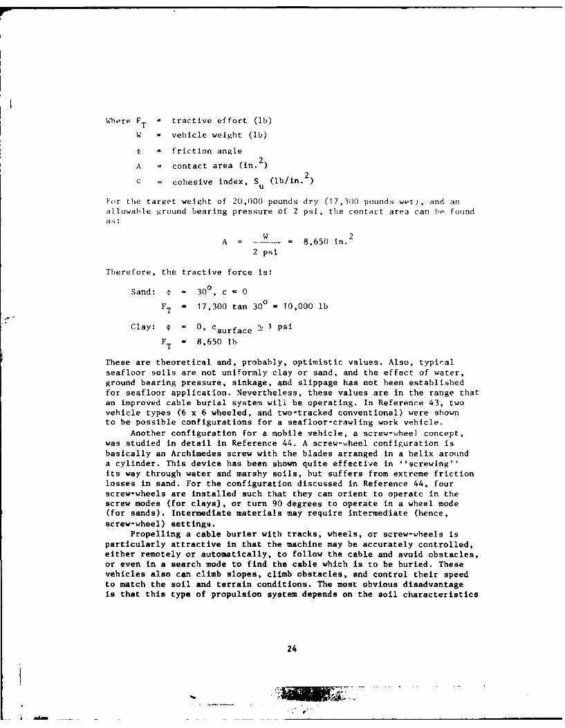
Vhere FT = tractive effort (lb)
W = vehicle weight (lb)
t = friction angle2
A = contact area (in. 2)
c = cohesive index, S (lb/in. )
For the target weight of 20,000 pounds dry (17,300 pounds wet), and anallowable ground bearing pressure of 2 psi, the contact area can be found
w 2A - 8,650 in.
2 psi
Therefore, the tractive force is:
Sand: o = 300, c = 0
FT = 17,300 tan 300 = 10,000 lb
Clay: = 0, csurface - 1 psi
FT = 8,650 lb
These are theoretical and, probably, optimistic values. Also, typical
seafloor soils are not uniformly clay or sand, and the effect of water,ground bearing pressure, sinkage, and slippage has not been established
for seafloor application. Nevertheless, these values are in the range that
an improved cable burial system will be operating. In Reference 43, twovehicle types (6 x 6 wheeled, and two-tracked conventional) were shownto be possible configurations for a seafloor-crawling work vehicle.
Another configuration for a mobile vehicle, a screw-wheel concept,
was studied in detail in Reference 44. A screw-wheel configuration is
basically an Archimedes screw with the blades arranged in a helix arounda cylinder. This device has been shown quite effective in ''screwing''its way through water and marshy soils, but suffers from extreme friction
losses in sand. For the configuration discussed in Reference 44, four
screw-wheels are installed such that they can orient to operate in the
screw modes (for clays), or turn 90 degrees to operate in a wheel mode(for sands). Intermediate materials may require intermediate (hence,screw-wheel) settings.
Propelling a cable burier with tracks, wheels, or screw-wheels is
particularly attractive in that the machine may be accurately controlled,either remotely or automatically, to follow the cable and avoid obstacles,or even in a search mode to find the cable which is to be buried. Thesevehicles also can climb slopes, climb obstacles, and control their speedto match the soil and terrain conditions. The most obvious disadvantage
is that this type of propulsion system depends on the soil characteristics
24

for mobility and drawbar effectiveness. Since seafloor soils are generally
weak, variable, and often times their characteristics unknown, vehicleperformance cannot be predicted with any confidence. This, coupled withgeneral lack of experience in seafloor trafficability, makes it impossibleto judge whether a burial system propelled with tracks, wheels, or screw-wheels will be successful. Finally, these types of running gear are rela-tively complicated mechanisms that may impact on the reliability of theburial system.
Thrusters. One of the most common means of propelling underwatercraft, thrusters, includes open and shrouded propellers and jet pumps.Propeller theory is well known, although propeller design is iterativein nature. Since a prop uses the water medium to develop thrust (asopposed to soil for traction), it is relatively straightforward to pre-dict the performance of a propeller driven machine. Propeller efficiencyis defined as:
e =ehpp slip
where e = propeller efficiencyP
ehp = effective horsepower = thrust x velocity
shp = shaft horsepower
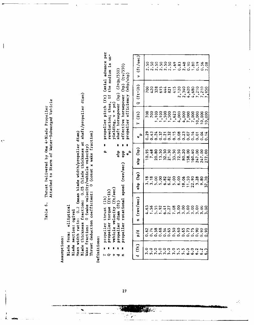
It can be seen that if the vehicle is stationary, the propeller may begenerating large amounts of thrust, but the ''efficiency'' will be zero.Thus, several propeller configurations are considered from the standpointof thrust and power rather than efficiency. A preliminary analysis onducted and non-ducted propellers iA summarized in Tables 5 and 6. In onecase, two 5-1/2-foot-diameter non-ducted propellers will provide 8,000pounds of thrust at a burial speed of 2.48 ft/sec (1.5 knots), requiring160 shp. In the case where the machine is stalled, two-ducted propellers,4 feet in diameter, can supply 9,400 pounds of thrust at 160 shp. Ingeneral, ducted propellers are more ''efficient" (i.e., require lessshp for the same output conditions) by 10 to 30% than non-ducted propellers.One major advantage of thruster propulsion is that, by operating at aconstant thrust level, the machine speed will vary as a function of thesoil resistance. Thus, in tough materials, the machine will proceed moreslowly than in soft materials, and overstressing of the excavating meanswill be eliminated. Also, props may be directly driven from submersibleelectric motors, or by hydraulics, and may be articulated to providecontinuous steering control.
Cable Traction Propulsion. Pipeline burial systems generally straddlethe pipeline, depending on the pipe for guidance, and some use tractiondrives to pull themselves along the pipeline. The most distinct advantageof a cable burial machine which pulls itself along the cable is that itclearly will follow the cable. The breaking strength of 18,000 pounds forunarmored SD cable is adequate for a system that meets the target force
25
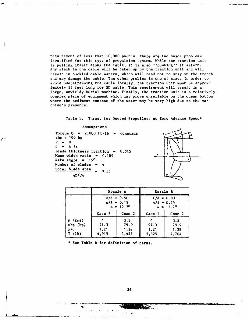
requirement of less than 10,000 pounds. There are two major problemsidentified for this type of propulsion system. While the traction unitis pulling itself along the cable, it is also ''pushing'' it astern.Any slack in the cable will be taken up by the traction unit and will
result in buckled cable astern, which will tend not to stay in the trenchand may damage the cable. The other problem is one of size. In order toavoid overstressing the cable locally, the traction unit must be approx-imately 35 feet long for SD cable. This requirement will result in alarge, unwieldy burial machine. Finally, the traction unit is a relativelycomplex piece of equipment which may prove unreliable on the ocean bottomwhere the sediment content of the water may be very high due to the ma-chine's presence.
Table 5. Thrust for Ducted Propellers at Zero Advance Speed*
Assumptions
Torque Q - 2,000 ft-lb - constantshp 100 hp
v 0d - 4 ftBlade thickness fraction - 0.045Mean width ratio - 0.189Rake angle - 150Number of blades - 4Total blade area - 0.55
7rD2/4
Nozzle A Nozzle B
L/d - 0.50 L/d - 0.83s/1 - 0.15 s/i - 0.15a - 12.70 a - 12.70
Case I Case 2 Case 1 Case 2
n (rps) 4 3.5 4 3.5shp (hp) 91.3 79.9 91.3 79.9p/d 1.21 1.38 1.21 1.38T (lb) 4,915 4,453 5,325 4,704
* See Table 6 for definition of terms.
26
III.m
1WU
OQJO oa))MO C o
"0 000 00O 0O' I
a~ W
W- -0)C C 1 - 0 L
ca 4).. u
0 4.i~ 0 . 0)Q ) ..- 0 .- 4 C y
:3 *-. W W 0
CJ. a) U.) 40-4 4) '-4 4.J 41 1 0 W.'- ,- 0 00 40 0 0 0
-4>0. 0 44 . 0 0 0 J 0>) 4) C. 4) ' 3. @ 4 r-. r- - - Lf LnU 'D
W.- 0 4 0 0 > 4
o. 0. 0 .0 -4 .4-4 4) CL k w M r- T -. T0r1.n4 W .4) 4= -4W cn InC - -1
9Q -.4 U) 44 >1t 4 . ; o o 0
0. -4 . W . .0.. .>1 0 C 0 Ad W04. 0 r-0mC nC l C04 -4 0. d 0 1.. W- 4-1. - n; r M% -1-~~ S . 0 C-4 N.. C14.00 0 0 00 0 0
51.. - ->
-A 0.0 0. > ~14 " 0 4) 00 U0 000 4C )0 00 W0 0
d) ~WU G) uW - n Y
W 12 4 4L . 4.O W 1:C 4 r=3 o-.. 0 C14
:1 -,
WUU-44. 1to-o 0
4) -. W Uj 4j ~
0 01 q -0 - M% n'-0 000 CC-4 -44 A '4) > -, -H
C'0 ".'-0 0 '-'--4 0
1)U 4 V) 00 $ > 0 o'oc. ooWoC-404- --IJ W L4000 n00
(00 1.40 -4 .0 0- 4- DLO00 % n% 0 rr4 :3 Lii0 UG)4
00 4 0 .. o 0C00m - 0 4) VC t a U W 4 -
0 4-.0.'4 4JG 0)000) OU) -40-
CL ~ ~ .. 00 0. 00000000000000 .. .. ..
:303 on pq o 4 CY >
0 %4
27
I A ~ i _ _

Oscillating Valved Disk Propulsion. The last propulsion means thatwas investigated for deep-ocean cable burial is an application of aninnovative idea called the Alveolator concept f42]. In essence, whena body (such as a disk) is accelerated through a fluid, there is a massof the fluid which must also be accelerated. This is an ''added'' orvirtual mass. In the case of a disk accelerated through water, the added
mass term is given by
M -I P 8 3a d w 3
where M . added massaK d a added mass coefficient (1.2)
Pw . mass density of water
r - disk radius
The acceleration of this significant mass produces a force that may be
used to drive a second body to which the disk is attached. If the disk isvalved such that the valves are closed when the acceleration is in a
direction to provide the desired force (Figure 5), and the valves are openwhen the disk is accelerated in the opposite direction, a net driving forceis produced. A mathematical model was developed for a cable-burying machine(plow) propelled by an Alveolator disk. Representative values were selectedfor machine weight, soil shearing and viscous forces, and drag forces. Adigital analysis performed on the computer showed that the system movedalong the seaflooL with a net velocity of 0.25 ft/sec, but that the motionwas oscillatory with an amplitude of nearly 4 feet. Optimization of thesystem parameters and the driving function may reduce or eliminate themachine oscillation and increase the speed. The major drawbacks of thissystem are the engineering difficulties involved in implementing thevalved disk means and that the concept is unproven except by mathematicalsimulation. Note that if the machine is fitted with a plow, the plow
vibrates due to the vibration of the machine, and the force required forplowing may reduce considerably due to plow vibration. The computer resultsshowed that the average power required for propulsion and excavation is172 hp. Since the driving function for the disk has a large amplitude(5 feet) and low frequency (1 Hertz), a double-acting hydraulic ram canbe used as the prime mover.
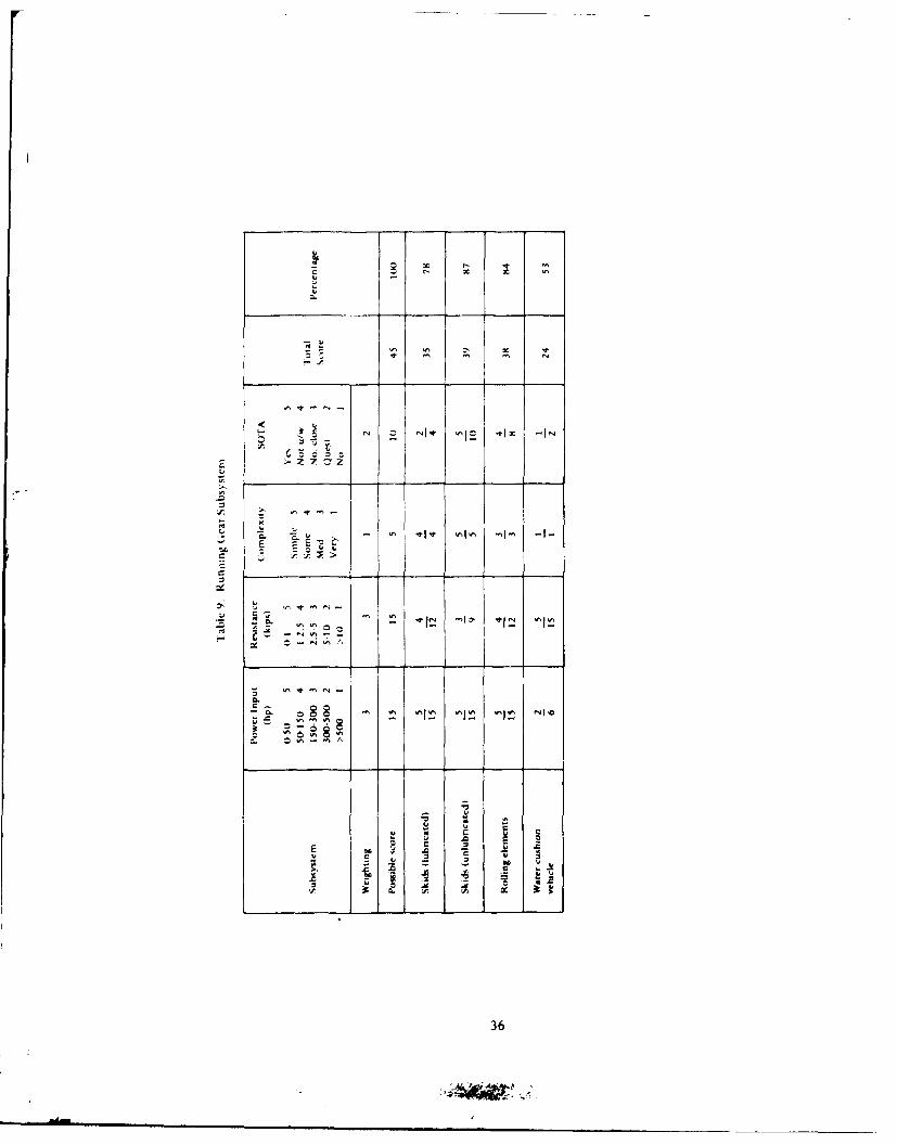
Running Gear Subsystems
A major component of the resistance to forward motion for a cableburial machine is the interaction between the machine's running gear
and the soil.
Skids. The mechanism for predicting the resistance between a skidand the seafloor is not well established, but is generally considered tobe dominated by friction in sandy soils and be shearing resistance in
clay soils; that is,
28

I
.-o
L I

Ff = -A S for clay (1)2 2s u
Ff = w N for sand (2)
where Ff = ''friction'' force (lb)
A = skid area (in. 2 )5
S = surface shear strength (0.5 to 1.0 psi)u
N = weight of machine (ib)
'" = coefficient of friction ('%0.5)
The problem with using these formulas directly is that the effectof water and bearing load on the coefficient of friction and on the shearstrength is not known. To get an estimate of these effects, data fromtowing Sea Plow III with the plowshare disengaged show the following:
N = 28,600 lb
A - 12,500 in.2
S
F = 5,000 lb (no plowing, water drag, or cable dragavg forces included)
This force may be used to obtain effective friction and shear strengthvalues from Equations 1 and 2.
2 FfS Ff 0.8 psi
Ueff AFf
Ueff - 0.2
The target cable burial system weighs 17,300 pounds wet; therefore,
N - 17,300 lb
Selecting an allowable ground bearing pressure of 2 psi, the skid arearequired is
A 17,300 lb . 8,700 in.2
2 lb/in.2
Therefore,
F 1 A S - 3,500 lbLiay s ueff
F - eff N - 3,500 lbsand
30

Although these resistance values, coupled with those of several of the
excavation candidates, result in total drawbar force within the target
limitation of 10,000 pounds, it would be desirable to reduce the skidresistance to a minimum. It is reasonable to expect that a 50% reduction
in motion resistance might be attained by forcing water between the skids
and the soil to lubricate the interface. With a nominal skid area of
60 ft 2 , each of two skids can be 4 x 8 feet long. The following assumptions
are made
(a) Water flow from back of skids machine speed
(b) Water flow from sides of skids = 50% machine speed
(c) Water layer - 1 in. thick
(d) Supply pressure - 10 psi
P - Q p - 1(0.083 ft)[8 ft + (32 ft)(0.5)1(1.69 ft/sec)}
(10 lb/in. 2)(144 in. 2/ft 2)[hp/(550 ft-lb/sec)]
P - 9 hp
Thus, an additional 9 hp may reduce the drawbar force required by 1,750
pounds for sand and for clay.The major advantage of using skids to support the burial machine is
their simplicity and reliability. However, their ability to -iegotiate
obstacles is limited, the resistance prediction outlined above will be
affected greatly by how much soil is pushed ahead of the skids, and the
water lubrication technique is not proven technology and must be tested.
Rolling Elements. One means of reducing motion resistance due to the
running gear/soil interface is to provide passive rolling elements such
as tracks or wheels. Rolling elements have the capability to negotiatesome obstacles, as discussed in the propulsion section. Liquid-filled
tires can be designed to vary the nominal unit ground pressure, which
could prove beneficial when different soil conditions are encountered.
Bekkar 143] predicts that the motion resistance for wheels or tracks
is 1,000 to 1,500 pounds, significantly less than that for unlubricatedskids. Also, differential braking or articulation of the rolling elementscan be an aid in machine steering. The drawbacks of rolling elements
include their complexity (relative to skids) and the uncertainty in motion
resistance and trafficability predictions.
Water Cushion Vehicle (WCV). A WCV is similar in concept to an aircushion vehicle, except that water flow and pressure is used to supportthe platform at the water/soil interface vice air at the air/water
interface. A distinct advantage of the WCV concept is that the machine
frame/soil interface is separated by a layer of low-pressure water. Thus,
the motion resistance is reduced to that force necessary to shear the
water layer, or essentially zero. Reference 45 describes a WCV concept
31

which, assuming roughly half of the power supplied is used for thrust,
requires approximately 750 hp for the cushion flow. Since the target
cable burial system is half the size of the concept described In Reference
26, a WCV cable burier would require on the order of 375 hp for cushioning.
Because the pressure is vei' low, the flow must be large, and there maybe a significant problem with scouring under the vehicle. Although aWCV may' provide a means of eliminating vehicle frame/soil resistance,it is an unproven concept, requires large amounts of power, ma; have
stathilltv problems, and its low (6-inch) ground clearance will (:au eproblemn, in negotiating obstacles.
CONCEPT SELECTION
To make the concept selection from the various combinations of ex-
cavation, propulsion, and running gear subsystems, parameters wereidentified for comparing the combinations. Each parameter was also assigned
a criticalitv or importance factor. Each system or subsystem was judgedon its capability to meet the design parameters, and this capabilitywas then weighted by the importance factor. In general, the higher the
score, the better the system.The importance factors were given the following values:
4: Essential for the system to meet its mission requirements.
3: Important from the standpoints of feasibility and meeting target
design parameters.
2: Desirable, to increase reliability, probability of success, and
to keep development time and costs within reason.
1: Little impact on the probability of success, but still important
to system reliability, efficient performance, and ease of operation.
The performance and design parameters are discussed below in their
order of importance. Score ranges are shown for each parameter in Tables 7through 11.
Cable Damage Probability - (Weighting Factor: 4). An essential feature
of a cable burial system is that it bury the cable without damaging it.
Scores are biased to reflect that even a moderate chance of damaging
the cable is unacceptable.
Total Power -(Weighting Factor: 3). The power to be supplied throughan umbilical was calculated, and each concept rated according to its
power level.
Force Requirements - (Weighting Fact6r: 3). The total motion resis-
tance, including cable drag, soil resistance, and other drag forces,
was calculated, and each concept rated according to its force level.
32

q - (Weighting Factor: 3). The burial system mustperform in sand and clay, and it would be ideal if it could cut rocka- well. Concepts were downgraded significantly if they were limitedto either sand or clay.
- (Weighting Factor: 3). Since the burial systemmust be capable of burying previously laid cables, a good capabilityfor steering the machine to follow the cable is important. This factoralso impacts on cable damage probability.
": ct ;,'7" (Weighting Factor: 2). Meeting the weight andsize target values is desirable from the standpoint of ship handling,transportation, and ease of operation.
I ' C' *oPt , ., - (Weighting Factor: 2). The requirement that
the system be operable from ships of opportunity was judged, takin). intoaccount ship power, control, handling, and predicted deck space require-ments.
' -w-A -; - (Weighting Factor: 2). Since a cable burial svstem
is needed soon, concepts were downgraded if they reouired extensive re-sear-h and development to prove their validity, or if the probability ofsuccess was judged to be poor.
bs>> E. 'f : Z - (Weighting Factor: 2). The obstacles consideredin this category included buried or partially buried items such as rocks,cables, or debris. Concepts were downgraded if encountering such an obsta-cle would severely damage the machine or cable, or preclude continuedoperation.
" ' - (Weighting Factor: 1). The complexity of the system
impacts mainly on reliability and maintainability of the system. A complexsystem will require more comprehensive design and testing efforts, butwill have minor impact on the eventual success of the system.
The selection process was done in two stages. The major subsystemcandidates (excavation, propulsion and running gear/subsystems) wererated and selected, then the survivors were combined into the variousoverall system candidates, and these candidates were rated.
Excavation Subsystem (Table 7)
The candidates under consideration include vibratory plowing, waterjetting, auger trenching, and trenching. For a cl.imbmilling trencher, ascore of 6 is possible as a bonus for aiding in propulsion. Vibratoryplowing and water jetting scored the highest, specifically because oftheir low probability of damaging the cable, high probability of success,and minimal effect of buried obstacles. Climbmilling bucket trenchingalso scored well enough to be retained. Although the excavation method isrelatively complicated, the force assistance is a considerable benefit.The other candidates were downgraded mainly in the complexity and effectof buried obstacles categories. Vibratory plowing, water jetting, andclimbmilling bucket trenching are retained as candidate excavationsubsystems.
33
-J . ... . . ...... ~.... . ....... .. ... .

~. -I--
-I
C
_______________ - -
1
o *~
~ ~ ~-.
~.
*1~
-- 0 ~ 0' '0
r-. N C
-
'--1-'
2 ~
~ ~EEcc
.'.' -t -~ .... -
I
-. .-.
~ 0
~J4
Z 7 Z7
.~ 4- -
-~
-~Io' ''Ia' 10' '~jo. ~I0' ~Io ~Ic
~. ~7 7
0
oE - ~ -~I-~ ''V -V -I- -I- -I-- -1-
..n *~
.'-. 4- - -
~r, f
I
__
____ ~ I* 2 .~
~ ___
"-I,
0
~-~---1~
~
1'0
0.
0
~. ~-
-'
U
C U U
I.
.0 ~ I' -~
.5-'0
U~ '1-
0 --
0~0~ .0
~' U'-'
-~ 00 ~
.0
0

}Z
" ° "I i Ia -
> 7 z Z
- z
C. - - - - I -
~E
22
35
- I
AT . 0
E d
CL
- - - -o
- CcCz
LA a
C3
tk ZC I'
0
CC
~~ID
C/CN
Cd -I 0I CD 0. .11 fnI 0 r- 0 cn000a4 - 00 0 00
Ia.a
.C di $4 C)000 C) 00o 0 00 000C 0 00 0 0)0 0CD0( u CJ 0 Ln 0 L 00C)0 0 00c Lfl i c 0 0 0 Ln e'l
$ -, r.- C% c L 'C1 ID Ll CN ID r- 'C L% -T uLn - - C
Cl .f -4 4 ,O-40 0 0~&J wl J 0
cfl0 W 3 4 lCi 4wC .- I00 .4 to r. r-IC 00 00 r. to 4 w
-14 4 0 9 -,4 ~0 -"o 0zE4 ~ ~ - UIE
009 - a
37

)0 M. 0C 4 14
0;74
CL 0 3t N- NI. 4) f-N e
cii
00L)
aj I.44 N. N.0L 0 7 f 0 0 -.W. 0 C4 . - 0-
~~4 4c. II NI II NCN
) 4 C) a~. C) c c 0 0 0 c- 000"44 *.0 0e00 0 (40 0 0L 00 L)00f
0 c44 __ _ _ _ ________?C14C1
oo 0 w - 0
4)~~~b >0- 0~~0~ ' 0 . 0 0. 0 -0 04.to4 00 0.- 04 I- 0 4
a0 A.jS -4 -j -11 )c - 1a
.ld. 14'J0 0 41w 0 00 4 0 0 w 0 u r 64 w I'dLf0A E-~ fa a a a4 a > a 4 a z a -a d a aH
ci.4 00N4 - CIN - nj-. -. 'CJ ~ -N0 z
-~ S 38

4))
41
'4 0
0~~ '00C1 c
:3 0) r- ID - % .4.0o sO- s.0C .4'Tr-C' r- 0
a 0 -N -1 C'J C'J
4)n1 a, L (7 L a'l 1f4 a%~ O4 0C fl V'en4. '0 en - .0
0r 4 0 00 0 C) 0 0 0 0 0 0;c'41 L
0
0 4) X~
>, >s)'' 0 -,t cy 0 -4 m 0 CD. 0 Ien4 r- 0 coO'l C 00 V)0)0 w ~ 0-C -0 - CJ 0 0-
A0 A 344J -
4) It 49 4t K K4) W C) 00 0 00 C 00C0 00C)0 0) 00 00(D0 000Cu -4. 00 0 C00 00 0 0L~NC cw :5 -4 L/'JC'.Q Lf) " %D. r-. '.0 1n a Lf4 . IT P .'NO0 if','.0r-0 V a a a ar a4 a a1 al -^ 4 14 a7
Ua. d) v) C04a om l: cl; -. - 'r, CD 0- CD LA , -N~ r
.0 .0 -4.4) 41 V1-
4 )4 d4 w4 $ 4 .-I 1 . 0 -0 ) 0 0 W -n )4 (A -4) r4
1- 4 a)). 1 41 8 -Ai 411. 9: Ai= A.cm '-'o 4 0 04M) $4 9) ) '-w,- 0a 40 w -4 --. 46 w--.. 0)u
lu 0).0 E -1 " 'a : 0)bu ) 4 "0 0) V 4U))14) :3 0 a . :Ln - -4 0.0 w *,4 Aj r.4 AJi.. 4 $4I. V~44) w- .4 4) I..
4 0 (1)"4 bd o bdo.C 0 cc $~4 A A
4) ..4 0A '. - 00 0
0 - - 0 c-0
39
AddM .. . ....
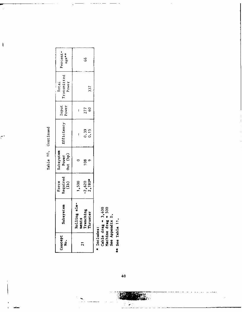
71Ji
0 a t'0
n aj r,0
a)l
-40 0.
44,
00
Ea 0.' 0 O0
a. 41
u~4 0 1 00j
w 3 -4 4 00
0 -1*tr.144 C14J ~
0 1-4 C) -
ul ~ ~ 93 14 V
000@3 *1 w co 44 @
00 - I'4@3Iwo
01C.. 4 E4
04
-I-c

' cc .j t I z- 1 -1 * -1= - -t -j r S% t
.,' E 1;-I-
0 1 = I-tx - 1 -l -V. Ic _I - 1
B r .E c 1K1 12 12 1 : l I 1
"*o "I _10 10"lB10 -2 1 1 - c I
i PI
- A~41

x - t. > - t - lo -i t ~ l P X - h I
72 4
o -c
CL__ 4 J
,~ .t -~3-
2fF ___42
~ -ic tI~c .be .7

Propulsion Subsystem (Table 8)
Propulsion system candidates include towing, tracks/wheels, thrusters,and the alveolator concept. Note that the power input for towing is zerosince it is assumed that the support ship already has the shaft horsepower
for towing. Towing was downgraded mainly in the limitations it places
on the support ship and in steering/control, which impacts on its abilityto bury previously laid cables. Nevertheless, towing scored high in otherareas and is retained as a propulsion candidate. Tracks/wheels scored
low in the state-of-the-art and complexity areas, but scored well enough
in control and ship support requirements to be retained. Thrustors scored
the highest in spite of the high power requirement. The alveolator concept
was discarded due to its complexity, the fact that it is unproven, andthe predicted difficulty in controlling its direction. Thus, the remaining
propulsion concepts are towing, track/wheel, and thrusters.
Running Gear Subsystem (Table 9)
The potential candidates include lubricated and unlubricated skids,
rolling elements (wheels or tracks), and a water cushion vehicle (WCV).
The WCV scored very low in power, complexity, and state-of-the-art areas,
and, therefore, was eliminated. Of the remaining concepts, it remains
questionable whether or not lubrication will effect the predicted force
reduction; therefore, lubricated skids were rated questionable in thestate-of-the-art parameter. Nevertheless, the score was high enough to
retain lubricated skids along with unlubricated skids and rolling elements.
Overall System Evaluation (Tables 10 and 11)
The excavation, propulsion, and running gear subsystems that were
retained were combined in all possible ways to select the best overallconcepts. Table 10 presents a force and power summary of the twenty-one
combinations. Note that the ship power required for towing is not includedin the power estimate. Also, the concepts with track/wheel propulsion
have rolling elements for the running gear subsystem because of thepropulsion subsystem.
Each concept is rated in Table 11. The results show that all theconcepts that included trenching as the excavation means scored low
no matter what the other subsystems were. These low scores are due mainlyto complexity, obstacle effects, chance of success, and, to some extent,
power. Towing also scored low in all combinations because of the lack
of steering control, and the impact on ship support requirements. Thefour best scoring combinations are:
Excavation Propulsion Running (;earConcept Subsystem Subsystem Subsystem
16 and 17 Water Jet Thruster Skids (lubricatedor unlubricated)
I3 and 14 Vibratory Plow Thruster Skids (lubricatedor unlubricated
43
* A1Ib
SUMARY
1. Water jet trenching is basically simple and proven technology, but it
requires more power than other trenching systems to excavate at a speed
of 1 knot. Water jet trenching is particularly suited to burying repeaters
and cable anomalies.
2. Trenching augers must rotate at approximately 5,000 rpm to trench at1 knot and are susceptible to damage from rocks buried in the soil.
3. Conventional (upmilling) trenching has a high resistance force, is.usceptible to damage when encountering buried obstacles, and the 1-knotspeed requirement is in excess of normal maximum trenching speeds.
4. Climbmilling trenching provides a very desirable propulsion assistance
force, but is susceptible to damage from buried obstacles, requires too
much power, and may be unsuitable for the high excavation rate resulting
from 1-knot forward speed requirement.
5. Vihratory plowing has been shown to reduce normal plowing resistance
forces by 90-99% on land, is relatively insensitive to damage from buried
obstacles, and has achieved speeds in excess of I knot in some land soils.In addition, the vibration allows the plow to achieve and maintain maximum
penetration; thus, the burial machine can be made lighter. Vibration
also aids in dislodging subsoil rocks. The power requirement is in the
middle of the acceptable range, and the system is basically uncomplicated.
Auxiliary devices must be employed to bury repeaters and cable anomalies.
6. Towing for primary propulsion imposes unacceptable constraints on
the support ship. The ship must have adequate power to tow the systemand must maintain a precise heading and course while traveling at 1 knot.This quality of control requires bow thrusters and, ideally, stern thrusters
as well as excellent navigation feedback between the ship and the buryingmachine. Also, towing allows only gross course changes of the burying
machine. Towing via the umbilical cable may be employed as an auxiliary
propulsion means for a self-propelled burial system.
7. The oscillating disk propulsion means is unproven technology, may
result in a cumbersome and complex system, and may lead to steering and
control difficulties.
8. Track/wheel propulsion has excellent steering and control features,
may prove to have good slope-climbing and obstacle-climbing ability, andrequires nominal power. However, tracking depends on the seafloor soil
properties and may not allow selecting one configuration which willperform in all soils. Generating thrust with tracks or wheels has not
been proven for seafloor operation.
9. Thrusters (shrouded props) are proven in deep ocean use, and theirperformance can be predicted since they depend on a known media (water)for thrust. They can be controlled easily in both magnitude and direction
of thrust to provide excellent steering and control capabilities. Thrusterslend themselves to direct drive with electric motors that reduces powerconversion losses, compensating for the inefficiency of the thrusters
themselves.
44

10. Skids are the least complicated running gear for a bttom-traversin.'
machine and have been used successfull' in the past. The force reqiir edto move unlubricated skids is ncar 4,()()) pounds, but it is expected t0(it
this force can be reduced by waiter ubri(ating the cotat Slar ir
11. Rolling elements, such as tracks or wheels, reduce resiistan(", tomotion and can provide some stta.ring control by differential hr kii'They must he large to reduce the nominal unit ground pres -ar i. ';inct-
they are rotating, they, are somewhat compl icated and are so-ptto jamming from sediment.
12. The water cushion vehicle 1,i an unproven concept, req ir,,s larg,,
:mounts of power, and the skirt flow may wash away the soil and ca ii-,
the system to jet itself into the seafloor. Vertical stability Ma% A lau
burial depth variations, and the small skirt clearance makes it dificultto operate in non-level terrain.
CONCLUSIONS
1. It is concluded that the deep-ocean burial system concept with thebest chance of success, which will provide positive burial depth andwhich meets power, weight, size, ship support, and speed reqiirements,is comprised of the following major subsystems.
Excavation subsystem - vibratory plowshare or water jet
Propulsion subsystem - self propelled by thrusters
Running gear subsystem - lubricated skids
2. The primary operating mode should be the burial of previouslylaid cables so that (1) the support ship need not be a cable layer,(2) problems with the cable-burying operation will not threaten thecahle-laying operation, and (3) repair sections or existing cables canbe buried. Towing may be used as an alternate propulsion means.
3. The auxiliary systems required include:
(a) Cable guide mechanism, hydraulically controlled to attach toand lift cable into feed shoe.
(b) Cable following sensors which feed data to machine controlsystem to steer the burying machine along the cable route.
(c) If vibratory plowing is the final excavation subsystem, a jetpump system capable of burying repeaters, hockles, kinks or cableanomalies which cannot be fed through the feed shoe.
(d) Fail-safe means to allow disengaging the cable should the burialmachine fail.
(e) Magnetometer or other device for locating previously laid cable.
(f) Obstacle avoidance sonar system.
(g) Television and hydrophones.
45

RECOMMENDAT IONS
It is recommended that preliminary investigation, including modelstudies, in the following areas be initiated in order to validate theconclusions drawn in this report.
1. Determine the drawbar force reduction resulting from an upwardcutting vibratory plow in typical seafloor soils. Determine the optimumfrequency and amplitude as a function of soil type and speed of advance.
2. Investigate the effect of water lubricating skids and feed shoesas a function of water pressure, nominal unit ground pressure, andflow rate.
3. Validate the pressure and flow required for jetting a 36-inch-
deep trench in seafloor soils.
Track/wheel propulsion scored highly in most categories, and might beexpected to result in a more efficient, more easily controlled, and moreversatile cable burial system than the propulsion subsystem selected.However, supportive information, tests, or experience with tracked systemsare not available, and, as such, these candidates were downgraded princi-pally because their probability of success is questionable. It is recom-mended that research, development, and testing be performed to determinewhether track/wheel vehicles are capable of meeting the needs of a cableburial system. Specifically, the drawbar force that such a system cangenerate, its slope-climbing ability, and its obstacle-handling capabil-Ities in typical seafloor soils should be determined.
REFERENCES
1. ''Cable Burial Mission Analysis (U),'' Chesapeake Division of NAVFAC,Washington, DC, 2 Apr 1975.
2. J. B. McBeth. 'The Use of Manned Submersibles for the Burial ofSubmarine Telecommunication Cable,'' IEEE Conference, Ocean 74, vol 1,Published 74, CH08973-OCC, pp 209-214.
3. Personal communication with Bill Sherwood, FPO-I.
4. Personal communication with Bill Gardner, FPO-I.
5. Anon. ''Excavators Dig in 40 Feet of Water on Both Sides of theAtlantic,'' Constiuction Methods, Dec 1967, pp 68-70.
6. J. G. Hendrick and W. F. Buchele. ''Tillage Energy of a VibratingTillage Tool,'' Transactions of the ASAE, 1963, pp 213-216.
7. D. MacQueen. ''Some Aspects of the Design and Use of Cable Ploughs -Part If,'' The Telecommunication Journal of Australia, Jun 1963, pp 52-62.
8. M. Senator. ''Penetration Rates and Stability of Motions of aHarmonically Forced Fore-Aft Vibrating Plow,'' ASME 73-DET-125, Sep 9-12,1973, Cincinnati, OH.
46
9. L. J. Scerbo and D. L. Pope. 'Bounding Solutions for Performance ofVibratory Plows,'' ASME 73-DET-128, Sep 9-12, 1973, Cincinnati, OH.
10. M. T. Sulatisky. ''Draft Reduction by Vibratory Soil Cutting,''Transactions of the CSME, vol 1, no. 4, 1972, pp 175-181.
11. A. G. Vedejs. ''Development of Machinery for Burying Telephone Cable,''
IEEE Conference record-supplement Special Technical Conference on Under-ground Distribution, Anaheim, CA, May 12-16, 1969.
12. R. J. Boyd and C. L. Nalezny. ''A Model of Vibratory Soil Cutting,''SAE 670750; Farm, Construction and Industrial Machinery Meeting,Milwaukee, WI, Sep 13-16, 1971.
13. W. F. Bilotta, et al. ''Upward Cutting Vibratory Plowing,'' SAE710729; National Farm, Construction and Industrial Machinery Meeting,Milwaukee, WI, Sep 13-16, 1971.
14. C. L. Nalezny. ''Analysis of Upward Soil Cutting,'' SAE 71078,National Farm, Construction and Industrial Machinery Meeting, Milwaukee,WI, Sep 13-16, 1971.
15. Personal conversations w/C. N. Springett, Ast. Mgr. Marine Design,
Santa Fe Engr. Services, Orange, CA.
16. Anon. ''North Sea Bury Barge 'Creek' 1976,'' Santa Fe EngineeringServices, 1975.
17. A. Welte. ''Hydro-Jet Deep Embedment Method,'' World Dredging andMarine Construction, Feb 1972, pp 15, 17-19.
18. R. C. Ewing. ''New Jet Barge Buries Pipe,'' The Oil and Gas Journal,Apr 1, 1974.
19. Anon, ''First Jet Deep Water Crossing in Gulf of Mexico,'' OFFSHORE,vol 32, no 9, Aug 1972.
20. Personal Communication with Frank Cunningham.
21. P. Schroder. ''Flush-Jet Bedding of Diver Cables,'' Institution ofElectrical Engineers, London, Journal vol 3, no. 31, Jul 1957, pp 418-419.
22. Anon. ''Conduits 'Hydro-Jet' Embedded for 750-Foot River Crossing,''Electrical World, Dec 16, 1963.
23. Anon. ''Water Pressure Cuts Trench for Conduit Placpd BeneathRiver Bed,'' Telephone Engineering and Management, Feb 1 1967, p 54.
24. Anon. ''Beluga - The Project With Many Firsts,'' Chugach Current,Jul 1967.
25. R. 1larmstorf and J. V. McBride. ''Underwater Apparatus for DeepEmbedment of Cables and Pipes in Submarine Subsoil,'' MTS Transactions,Joint Conference and Exposition, Jun 14-17, 1967, pp 657-662.
26. M. Miller, ''Cutting Frozen Ground with Disc Saws,'' CRREL TR-261.Jun 1975.
47

27. Advertisement, Ocean Industry, Oct 1969.
28. Anon. ''Marine Trenching,'' Undersea Systems Inc. (''Gopher'' -
brochure).
29. Anon. ''Unmanned Submarine Vehicle TM-102 for Trenching Operations,''Mar 4, 1975, Tecnomance s.r.a., Venice, Italy.'
30. 1. Van Daalen and J. van Steveninck. ''Shell Develops New Pipe Method,''Offshore, Aug 1970, pp 44-46, 48.
31. F. A. Angona. ''Cavitation, A Novel Drilling Concept,'' InternauionalJournal 'dock Mechanics Mining Science and Geomechanical Abstracts, vol 11,
pp 115-119, 1974.
32. Personal communication with Robert Elliott, NCSL, Panama City,"FL.
33. P. J. Valent and R. L. Brackett. ''A Comparison of Installation andProtection Techniques for Nearshore Electrical Cables,'' CEL TN (inpublicat ion).
34. J. van Steveninck. ''Pipeline Burial by Fluidization,'' 1975 OffshoreTechnology Co.,ference Proceedings, vol II, May 5-8, Houston, TX, pp 313-314.
35. W. C. Cooley and L. L. Clipp. ''High Pressure Water Jets for UnderseaRock Excavation,'' Transactions of the ASME, Journal of Engineering for
Industry, 69-WA/UnT-7, May 1970, pp 281-287.
36. Memorandum !42/H5L/aee of 21 May 1975, Subj: Recommendations onImproved Cable Burial System.
37. 11. A. Baxter and R. E. Mueser. ''The Development of Ocean-Cable Plows,''IEEE Transactions on Communication Technology, vol COM-19, no. 6, Dec 1971,pp 1,233-1,241.
38. Personal communication with Homa Lee, CEL.
39. W. J. van Heijst. ''Trcnching With Water Jets,'' World Dredging andMarine Construction, Sep 1969, pp 20, 21, 26.
40. M. M. Singh, L. A. Finlayson, and N. Monney. ''Water Jetting forUnderwater Cable Foundations in Coral or Rock Coastal Areas,'' IIT ResearchInstitute Project Suggestion 71-1060X, Oct 29, 1971.
41. J. M. Reynolds and A. R. F. van der Stein. ''Device Buries Pipe in164 feet of Water,'' The Oil and Gas Journal, Nov 11, 1974.
42. Memorandum L43/PKK/lh of 18 Jun 1975, Subj: ''Alveolator'' Concept
for Cable Burial System.
43. M. G. Bekkar. ''Diver Work Vehicle,'' unpublished contract reportto NCEL, 1971.
44. M. G. Bekkar. ''Engineering Optimization of Terrain - VehicleSystems - A Case Study of a Concept Analysis of a New Amphibean,'AC Electronics - Defense Research Laboratories, Santa Barbara, CA,,Feb 1969.
48

45. Ltr. from D. J. White of Global Marine Development Inc. to R. N. Cordy,
CEL, of 6 Jan 1975.
46. J. J. Myers, C. H. Holm and R. F. McAllister (editors). ''Handbook
of Ocean and Underwater Engineering,'' 1969.
47. Specifications, T-600C Trencher, The Diggin' Dutchman, 3-75-TC.
BIBLIOCRA714Y
1. Allen, R. C., 1). H. Ort, and L. M. Schindel. 'Submarine Cable Rout
Engineering,'' The Bell System Technical Journal, May-Jun 1970, pp
767-781.
2. Anon. ''Air-Powered Jet Line Trenching for North Sea Pipelines,''
Ocean Industry, Apr 1975, pp 355, 358.
3. Anon. ''An Analysis of the Sea Bottom Performance of the Equipment
Chassis Test Track,'' WNRE report 200-1, NCEL contract M62399-69-C-0046,29 Aug 1969.
4. Anon. ''Burial At Sea,'' Monitor Mt. States Telephone, Jul/Aug 1968.
5. Anon. ''Burying Ocean Cables,'' Bell Laboratories Record, vol 45,
no. 6, Jun 1967, pp 187-191.
6. Anon. ''Continuous Laying-In of Buried Cables by a Cable-Laying
Train Using the Trenchless Method,'' Rail Engineering International,
vol 3, no. 6, Jul 1973.
7. Anon. ''Dozers Give Robot Performance at Underwater Job Sites,''
Construction Methods and Equipment, Jul 1974, vol 56, no. 7, pp 90-91.
8. Anon. ''First Underwater Bulldozer Made in Japan,'' the Australasian
Engineer, Nov 1970, p 13.
9. Anon. ''Machines for Laying Underground Pipelines Without Trenching,''
translated from Stoitel'nyye I dorozhnyye mashiny, no. 5, 1971,
published Oct 1973, pp 6-8.
10. Anon. ''Milling Head Ditch Digger. . . ,'' Machine Design, Sep 5, 1974,p 3 9 .
11. Anon. ''Mobility on the Sea Floor,'' Engineering, Apr 1974, vol 214.
no. 4, pp 271-277.
12. Anon. "'Pipe Burying Barge,'' Compressed Air Magazine, Nov 1974.
13. Anon. ''Pipelaying Rig Cuts, Places on Covers in One Pass," Con-
struction Methods and Equipment, Mar 1973, pp 62-63.
14. Anon. ''Pipelire. Entrenching Device Announced,'' World Dredging and
Marine Conitruction, Oct 1974.
49
15. Anon. ''Pipeline River-Crossing Techniques,'' Pipes and PipelinesInternational, Jun 1974.
16. Anon. ''Plow Can Install 7 ,000 Feet of Line Per Hour,'' Engineering
News Record, Aug 8, 1974.
17. Anon. ''Plowing Machine for Laying Submarine Cable,'' Report No.4603, Cable Engineering Section, Communications Iivision, SurnimotoFlectric Industries Ltd., Apr 22, 1971.
18. Anon. ' 'Remote Controls Direct Pipe Line Trenchling ,rdge,''
Industry, Jan 1975, pp 72, 77.
19. Anon. 'Santa Fe Orders North Sea Pipe Bury Barge,'' OceanI lnd;trv,
Apr 1975.
20. Anon. 'Submersible Beaver on Assignment for AT&l,'' Ocean Industry,Sep 1973, p 198.
21. Anon. 'Submersible Proposed for Deep-Sea Trenching,'' The 011 andGas Journal, Jul 17, 1972.
22. Anon. ''Underwater Bulldozer Operates at Depths Down to 200 Feet,''World Mining, Sep 1970, p 9.
23. Anon. 'Underwater Trencher Remotely Controlled,'' Ocean Industry, May1974, pp 21-24.
24. Anon. ''Underwater Trenching Unit Lays Power Cable Across Bay,''Engineering News Record, Aug 19, 1971, p 34.
25 Anon. "Unmanned Seafloor Work Vehicle for Cable and Pipe LayingOperations,'' Ocean Industry, Nov 1974.
26. Anon. ''Vibrating Blade Helps Bury Telephone Cable,'' Machine Design,vol 46, no. 2, Jan 24, 1974.
27. %non. ' 'Wheel Trencher Cuts and Grades Wide Trench in Single Pass,
(on,,truction Methods and Equipment, Dec 1972, pp 43-45.
28. Armstrong, J. R. C. ''Submersible Plays Key Role in Laying Trans-tlantc C(thle,'' Ocean industry, Feb 1q75, pp 121-123.
29. halin, K. P. ''Underwater Jetting Equipment Buries Submarine Cables,''
Electric Light and Power, 1952.
3(j. Bekkar, M. G;. ''Tracked Vehicles for the Arctic,'' Machine Design,Ma. 30, 1974, pp 20-22, 24.
31. Bender, F. J. ''Two 4,300-Ft Subm~arine Cables Sunk 5 Ft D)eep inChannel Bottom,'' Electrical World, vol 162, no. 11, 14 Sep 1964, pp 20-21.
32. Black, S. A. and LT R. E. Elliott. ''Construction Assistance Vehicle(CAV) - The D)esign, Fabrication, and Technical Evaluation of an Experi-mental Underwater Vehicle,'' NCEL TR-762, Mar 1972.
50

33. Blake, W. H., and J. V. McBride. "Experience With New Concepts in
Design and Installation of Submarine Communication Cables,'' 21stInternational Wire and Cable Symposium, 1972.
34. Blain, R. ' 'Double Trouble Cable Job C;ets Done with Improvised ,;ir,
Telephony, Aug 7, 1972.
35. Brown, R. J. ''How Deep Should an Offshore Line be Buried for
Protection,'' The Oil and Gas Journal, Oct 11, 1971, pp 90-93, 98.
36a. Collins, S. V., and P. Reed. ''Submarine Trenches,'' Oil and Gas
Journal, vol 56, no. 32, Aug 11, 1958, pp 111, 112, 114, 115.
36h. CR-71.003, ''The Seafloor Excavator,'' Dec 1970, by Northrop
Corp. to NCEL.
37. Duncan, C. C. ''Plowing Cables Under the Sea,'' IEEE International
Conference on Communications, Philadelphia, Jun 1968.
38. Ehrbar, R. D. Session 13: Submarine Cable Communications Systems,TPM 13.2: Submarine Cable Laying, NEREM Record - 1963, pp 114-115.
39. Ewing, R. C. ''Seabed Crawler to Bury Pipelines Laid on Sea Bottom,''The Oil and (;as Journal, Jul 22, 1974.
40. Fischer, K. and A. Stuber. ''Placing Underground Pressure Pipes byMachine,'' Building Research and Practice, Mar/Apr 1974, pp 89-92.
41. Florence, H. V. and J. A. Frank. ''The Underground Piercing Tool,''
Journal AWWA, Wate: Technology/Distribution, Dec 1973, pp 800-802.
42. Gahbauer, S. F. ''Telephone Crews Plow Cable Under Lake Bottom in
Shallow Water,'' Engineering and Contract Record, Aug 1964, pp 57-58.
43. Gaus, J. N. ''Hydraulic Dredge Digs at Deeper Depths,'' Hydraulics
and Pneumatics, Dec 1974, pp 69-70.
44. t(ilbert, C. G. and J. F. Rinkin. ''Drag Reduction on a Rotating
oisk Usin a Polvynler Additive,'' Viscous Drag Reduction Proceedings of
the Svmposium on, Dallas, TX, Sep 24-25, 1968, pp 251-263.
45. Gordon, H. W., and W. R. Rockelle. ''Subsea Pipelaying Limits Deepen,''The Oil and Gas Journal, Jun 17, 1974.
46. (;unter, J. B. ''Submarine Cable Plow Leaves No Scar,'' Distribution
Engineering.
47. Huston, G. H. ''Brute Force Is Used to Plow-In Primary Cables,''
Transmission and Distribution, Jun 1967, pp 46-47.
48. Ishino, F., T. Horiguchi and H. Hata. ''2700-Channel Submarine Cable
System,'' Japan Telecommunications Review, Apr 1972, pp 68-77.
49. Johnson, G. L., and B. C. Heezen. ''National Hazards to Submarine
Cables,'' Ocean Engineering, vol 1, no. 5, Jul 1969, pp 535-553.
51
50. Johnson, L. E. ''Application of Waterjet Hydraulics to an Underwater
Excavation System,'' World Dredging Conference, 5th Proceedings, Hamburg,G:ermanv, Jun 11-15, 1973, pp 685-698.
51. Kawasaki, H., et al. ''Two Underwater Bulldozer Systems,'' OceanIndustry, Aug 1972, pp 34-35.
52. Kelly, M. J., and Sir Gordon Cudley. ''Transatlantic Communications,
An Historical Resume,'' The Bell System Technical Journal, vol 36, no. 1,lan 1957.
53. Kernnitz, L. A., G. P. Buck and L. F. Brisk. ''Vibrating Plows forD)irect Burial of Cables, Wires, and Tubing.''
54. Kloppenstein, 1). ''Salvage Vessel Over Comes Pipeline Sand Problems,''Ocean Industry, Apr 1974, pp 230-237.
55. Kunnan, F. ''Specialized Plowing and Heavy Duty Plowing Equipment,''IEE Conference Record - SuppIement, Special Technical Conference onUnderground Distribution, Anaheim, CA, May 12-16, 1969, pp 238-240.
56. LaCerda, J. ''New Day Dawns for Submersibles,'' Ocean Industry,May 1974, pp 25-28.
57. Laird, S. W. ''Power and Telephone Cables and Plowed-In Simulta-neously,'' Transmission and Distribution, Nov 1967, pp 72-73.
58. Maclay, J. C. ''Evolution of Cable Laying Plows,'' Bell LaboratoriesRecord, vol 40, Nov 1962.
59. Moody, L. F. ''Friction Factors for Pipe Flow,'' ASME Transactions,vol 66, no. 11, Nov 1944, pp 671-678.
60. Mori, K. ''Ocean Survey Techniques for Submarine Cable,'' JapanTelecommunications Review, Oct 1973, pp 275-279.
61. Morrison, J. ''Model Tests in Netherlands Indicate Optimum Conditionsfor Trenching,'' Oil and Gas Journal, vol 68, no. 18, May 4, 1970, pp146-148.
62. Morrison, J. ''Sub Sea Oil Completes Trials on New Submarine WorkVessel,'' Offshore, Mar 1972.
63. Munitz, A. J. ''Analyzing Failures of Ocean Communications Cable,''Undersea Technology, May 1966, pp 45, 47-49.
64. Nikolaev, A. D. ''Study of Underwater Working of Soil by Cutting,''(Trans.) Trudy (NIIMESKH) Minsk, vol 1, 1963, pp 295-309.
65. O'Donnell, J. P. ''Trenching, Pipe Laying Done Together,'' Oil and
Gas Journal, vol 59, no. 38, 18 Sep 1961.
66. Personal Communication w/Al Sutherland, FPO-1, 5 Aug 1974.
67. Personal Communication w/B. M. Buck, Polar Research Laboratory,Santa Barbara, CA (CAT).
52

68. Scholl, B., and W. F. Payette. ''1UR) Cables Plowed Underground,''
Fllectric l.ight and Power, Jun 1965, pp 66-67.
69. Scott, P. ''Way-Out Machines Lay New High-Traffic Cable,'' Popular
Science, Jan 1974.
70. Sheeh\:, (;. T. "Submersible Dredge Pump - An Answer for Deep Dredging,''World Dredging, Mar 1975, pp 25-27.
71. Shuman, W. H. ''Lake-bottom Cable Plow-in Proves Out,'' Electrical
World, Feb 15, 1973.
72. Specification Sheet, Case 475 Cable Plow, Form No. CE71972(;.
73. Sunobe, K., et al. "1Development of Underwater Bulldozer Systems,''Journal of Terramechanics, vol 10, no. 4.
74. Suzuki, K. "New Submarine Cable Burler With Guiding Equipment,''
Japan Telecommunications Review, Apr 1972, pp 61-67.
75. Turner, T. M. ''Submerged Dredge Pumps Increase in Acceptance,''
World Dredging, Mar 1975, pp 35-37.
76. US Patent Number 3,659,425; May 2, 1972, Pieter J. De Geeter,
"Method and Apparatus for Burying Pipeline.''
77. US Patent Number 3,638,439; Feb 1, 1972, Otto C. Niederer, ''Embedding
Cablelike Members.''
78. US Patent 3,803,856, Apr 16, 1974, Giovanmi Faldi, ''Process and
Apparatus for Achieving the Mechanical Trenching of a Pipe-Line in
a Sub-Aqueous Depth.''
79. US Patent Number 3,824,798, Jul 23, 1974, Kaisuke Shiroyama and TaheoYokoyama, ''Submarine Cable-Burying Devices.''
80. "'ideJs. A. G. ''Putting Telephone Lines Below Ground,'' Bell Lab-
oratories Record, vol 49, no. 1, Jun 1971, pp 13-21.
81. Wilson, J. V., R. D. Hitchcock and J. R. Mittleman. ''Emplacement of
a Ncavy Load Onto a Seafloor Foundation: Concept Development and Analysis.''NCEL TR-769, Jul 1972.
82. Wismer, R. D., and H. J. Luth. ''Rate Effects in Soil Cutting,''SAE 710179, Automatic Engineering Congress, Detroit, MI, Jan 11-15, 1971.
53

Appendix A
PLOW RESISTANCE FORCE AND POWER ANALYSIS
From Reference 36, the static soil resistance for a plowshare moving
through a cohesive soil (clay) is given by
F - S A + S N AfS u s U Cf
where F -Static soil resistance (Ib)
S Undrained shear strength (4 lb/in.2 )
A - Side area of plow (in. 2 )S
N - Dimensionless coefficient (1 10)
Af Plow frontal area (in.2 )
As the velocity of the plow increases, the static soil resistance must
be modified by a velocity coefficient, C (Figure A-i), and an inertial
term, F,, must be added: V
1 2F I - 2 - Af CD v
where P - soil mass density (a 3 lb-sec 2/ft4
CD - drag coefficient (0.7 to 1.5)
v - velocity (ft/sec)
The total force, then, is
F - F + FFTOT C v s
For the problem at hand, we have plow and feed shoe dimensions (Figure A-2).
w - 4 in.
h - 36 in.
9 - 120 in.
C - 1.09v
Thus,
A " 2 ht - (2)(36 in.)(120 in.) - 8,640 in.S
2
Af - w h - (4 in.)(36 in.) - 144 in.
54

a - 0
-H
"-4
0
cu
-o
(IOUI /1 A)
55

-n
C -~
N
C 3 0-4
E u-n 0.
0-z
cc
~ "~ -5
@~ -
U0
.2
56

For clay, then
FTOT = (1.09) [(4 lb/in.2 )(8,640 in. 2) + (4 lb/in.
2 ) (10))(144 in. 2]
+ 1 (3 lb-sec2 /ft 4)(1 ft 2)(1.5)(1.69 ft/sec)
2
2
= (1.09)(34,560 + 5,760) + 6
[FToT = 44,000 lb
Achieving a 95% reduction in force due to upward soil cutting vibration
0, 1 V CS
F = 2,200 lbFTOTredud_
In cohesionless soils, (sand) the situation is much the same, but F is
given by
F =Yb Nq Af D Yb As 4 D
2 2
where yb = Soil buoyant unit weight (1 40 lb/ft3)
N = Dimensionless parameter (a 90 for friction angle € = 400)q
D = Depth of embedment (ft)
u = Friction coefficient (2 0.5)
Therefore, we have
FTOT Cv F s F I
40 ib/ft3)(90)(1 ft23 ft) + (40 lb/ft 3)(60 ft 2)(0.5)(3 ft)
+6
- 1.09(5,400 + 1,800) + 6
FTO T ' 7,900 lb
A 95% force reduction due to vibration gives
F TO 4001lb
reduced
57
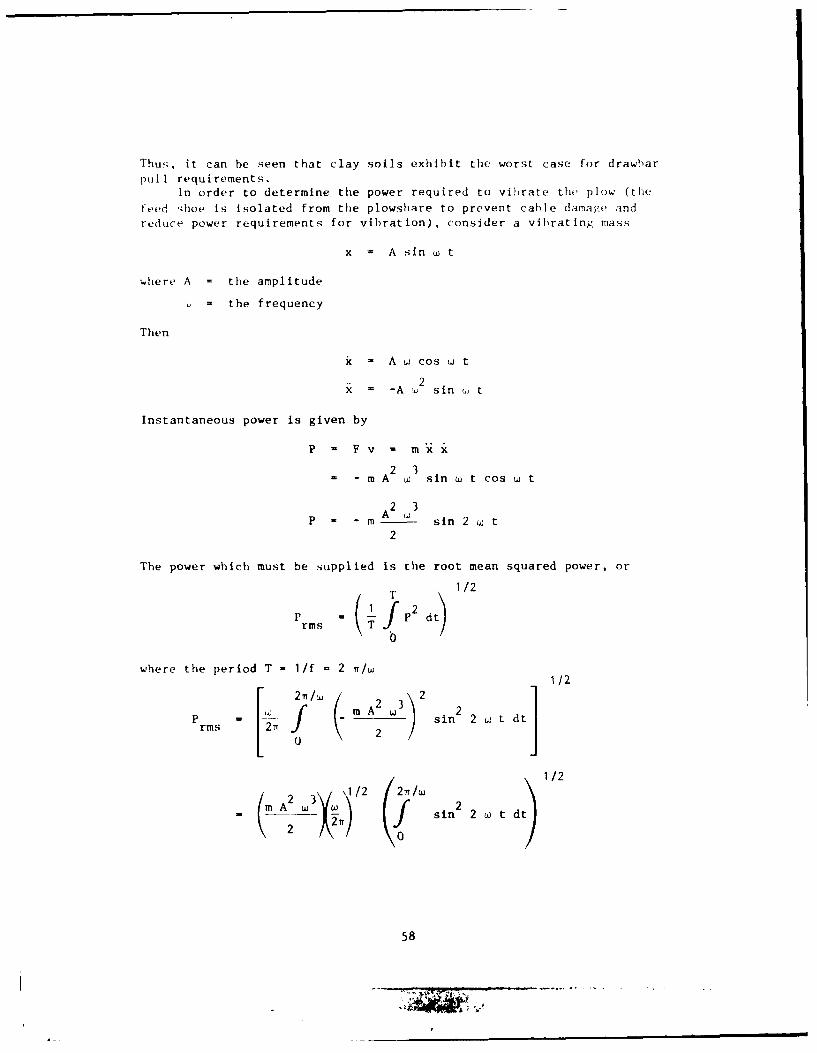
Thuu,. it can be seen that clay soils exhibit the worst case for drawbar
pull requirements.In order to determine the power required to vibrate the plow (the
feed ;hoe is isolated from the plowshare to prevent cable damage andreduce power requirements for vibration), consider a vibrating mass
x = A sin w t
where A = the amplitude
= the frequency
Then
x = A w cos w t
= -A , 2 sin w t
Instantaneous power is given by
P F Fv - mx
= - m A2 3 sin w t cos w t
A23P A sin 2 w t
2
The power which must be supplied is the root mean squared power, or
i . (~ 1T2 dt) 1/2
where the period T = 1/f = 2 /w ]1/2P rm = m A2 2 sin 2 2 w t dtrms 22Tf.
1/2
( m w 3 J 2 2 T, / w t
A2 0 sin 2 w d
58
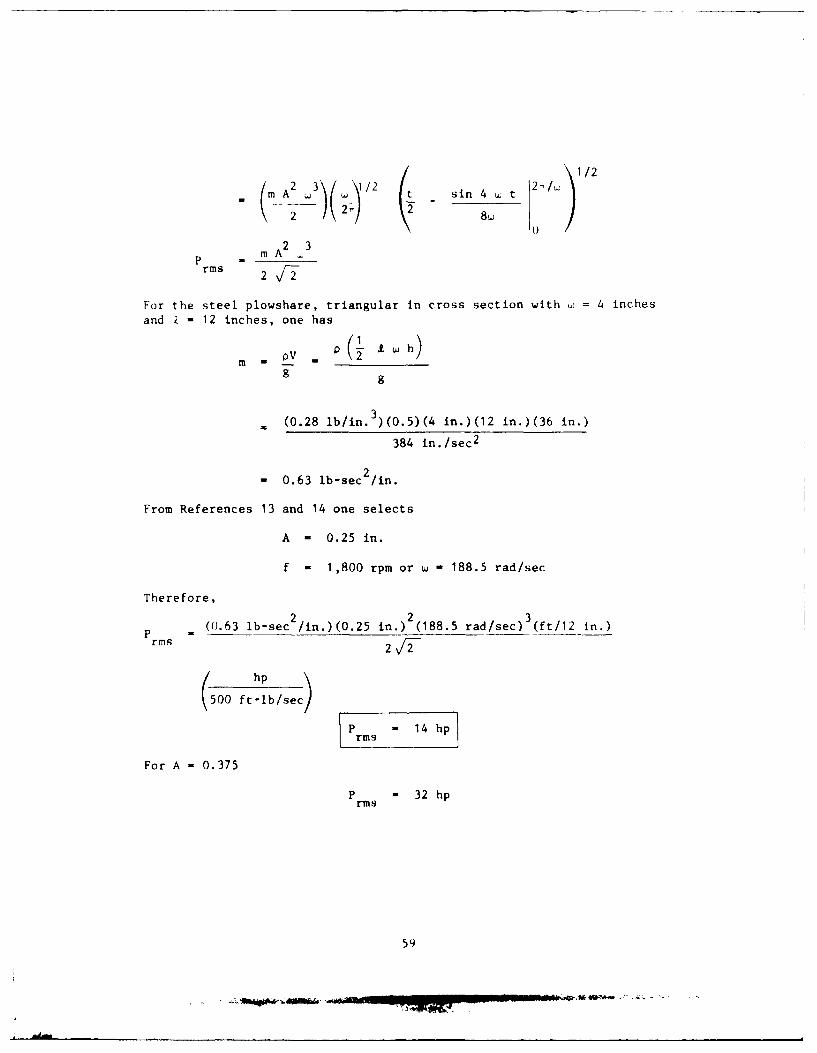
SA23 (1 112m 3\/1/2 t sin 4 W t
_ 2~ T_ -2 8\7
2 3p mArms 2 v1
For the steel plowshare, triangular in cross section with ui = 4 inchesand Z = 12 inches, one has
m V -(- Lh)
g g
= (0.28 lb/in. 3)(0.5)(4 in.)(12 in.)(36 in.)
384 in./sec2
- 0.63 lb-sec 2/n.
From References 13 and 14 one selects
A - 0.25 in.
f - 1,800 rpm or w - 188.5 rad/sec
Therefore,
2 2 3P (0.63 lb-sec /in.)(0.25 in.) (188.5 rad/sec) (ft/12 in.)
phrms2 2 -
(500 ft-lb/sec)P = 14 hp
rms
For A = 0.375
P - 32 hp
59

In addition to the mass of the plow, a mass of water, the addedmass, will also be accelerated and will add to the power requirement.Approximating the triangular plowshare cross section with a rectangular
cross section, the added mass is given by (Reference 46):
2ma K wI o a 9.
Tinot ion
21,
P X' r2
a
= - K P r a 2 9 A2 3 sin w t cos w tI1w2 A2 3
- pw a 2. A 2W sin 2 w t
2
where x - A sin w t
- A w cos w t2
= - A w sin w t
The power which must be supplied is the rms power
1/2
P P dtrMs T
where the period T = 1/f - 2 7/w
P / sin 2 2 w t dt
rms 2i a 2
K p w i a 2 A 2 3
2
60

Fhe approximated triangular plowshare is a 2 x 12-inch rectangular rod,36 inches deep.
a = 1 in. = 0.083 ft
= I ft
A = 0.021 ft
- =189 rad/sec
a/b = 1/18 = 0.056, K = 2.23 (Reference 46)
)"( ) .()83 t) (I ft)((.021 ft)>(189 r1d81-),c
2K( hp550 ft-lb/sec
P rms 0.2 hp
which is negligible.
61

Appendix B
ENCAVATION ANALYSIS FOR TRENCEING
CHAIN-DRIVEN BUCKET TRENCHER
In order to calculate the forces required to excavate a trench, somletrticher configuration must he selected. From Reference 47 one selects
chain speed - 9.2 ft/sec
bucket distribution 1 1 bucket/ft
The other parameters required are as follows (Figure B-i):
Depth of cut, D = 3 ft
Width of cut, w = 4 in.
Speed of advance, v = 1.69 ft/sec
Soil shear strength, S = 4 lb/in.
u d
Figure B-i. Trench configuration.
The total force required to cut the soil is the sum of the soil bearingresistance and the soil shearing resistance (friction) [38] or
A SFTO T - Fb + Ff - Af Nc Su + S u
where FTOT ' total cutting force required
Fb - soil bearing resistance
Ff - soil shearing resistance (friction)
Af a frontal area
N - factor , 3c
A - shear areaS
62
- = - . . . .. ....

Select ¢ - 60 degrees and the bucket length Z= 8 inches. The bucketrate Is
chain speed 9.2 ft/secB - - = = 9.2 buckets/sec
bucket distribution 1 bucket/ft
Soil removal volume rate required is
3V = w D v = (0.33 ft)(3 ft)(1.69 ft/sec) = 1.69 ft /sec
Then the bucket volume must be
V 1.69 ft /sec 3 V .= - - _ . -.. .. 0.18 ft /bucketb B q.2 bucket/sec
rhe depth of cut for each bucket is found by
Vb = w d b
orVb _ 0.18 ft 3
d = b =0.18 ft = 0.83 ft = 10 in.
w Zb (0.33 ft)(0.67 ft)
Thus, for each bucket,
Af = w d = (4 in.)(10 in.) = 40.0 in.2
and
A = (w + 2 d)ib = [4 in. + 2(10.0 in.)](8 in.) = 192 in.
Using these values in Equation B-i, one has
FTOT per bucket = SU (f N +
= (4 lb/in. 2) [(40.0 in. 2 )(3) + 192 in. 2 ]
F 864 lb/bucket]
An additional force is that required to lift the soil from the trench
63

F - V ; sinlift/bucket b s
w'hcre = soil density = 100 lb/ft
Ift = (0.18 ft 3/bucket)(100 lb/ft ) sin 6rj = l0 lb/bti ket
The maximum force which will be applied is th o sum of thr I ift t orr,,e antotal force times the number of buckets in contact wit t iit- i
D f tN, = ---- (bucket distribution) (1 hu( ketif t
sin , sin 60(0
= 3.5 buckets
F max (I TOT +F lift) Nb
= (864 lb/bucket + 16 lb/bucket)(3.5 buckets) 3,080 lb
The torque required
max = F (moment arm) = F (r + d)
where r is the chain drive radius = 0.75 ft (Reference 47)
Tmax = (3,080 lb)(0.75 ft + 0.82 ft) 4,840 ft-lb
The angular velocity is
chain speed 12 T rad= (9.2 ft/sec 2 i 12.3 rad/sec2 TT r rev / \(.5 ft)
Then,
P = - wmax max
= (4,840 ft-lb)(12.3 rad/sec) (550 ftb/sec)
P 5 ft lO/shp
Pmax -18h
The forces acting on the trencher are as follows:
64

iase 1: Trencher rotating in conventional (upmilling) dirction
F UP = -FTOT N sin - Flift Nb
= (-864 lb)(3.5) sin 600 - (16 lb)(3.5)
N_ P -2,675_ l b
F = -F N cosFWrD TOT b
= -(864 lb)(3.5)(cos 60 )
F = -2,620 lb
Case 2: Trencher rotating in forward direction (climbmilling)
F UP = FTOT Nb sin - F t Nb
= (864 lb)(3.5) sin 60 - (16 lb)(3.5)
F = 2,560 lb
FFWD = FTOT Nb cos
FF = 2,620-lbI FFFWD
62
EXCAVATING WHEEL
The same parameters and assumptions apply as in the chain-driven
bucket trencher, and the development is basically the same.
Tip speed = 9.2 ft/sec
Bucket distribution 1 1 bucket/ft
Bucket length, b = 8 in.
Wheel diameter - 8 ft
_T
Figure B-2. Excavating wheel confi guration.
65
-- ,

From Figure B-2
a = 12 = 3.9 ft
b = 3.0 ft
b otan - .. 38 0.66 rada
also,
0 = cos - 75.5 = 1.32 rad
Therefore, arc c = 1 r - 5.3 ft
B, " V b' d, Af, and A s are the same as for the chain-driven buckettrencher; therefore,
FTO = 864 lb/bucket
and
Flift ' 16 lb/bucket
The number of buckets in contact with the soil
Nb = (arc c)(bucket distribution) = 5.3 buckets
F = (F + F )N (864 lb + 16 lb)(5.3) = 4,460 lbmax (ToT + lift)Nb
= F (moment arm) = (4,660 lb)(4 ft + 0.82 ft) = 22,000 lb-ftmax
The angular velocity is
tip speed _2 ) rad- 9.2 ft/sec (2 2.3 rad/sec
r d rev / (r)(8 ft)
Then
P = T a (22,500 ft-lb)(2.3 rad/sec) (50 )Pmax_= 94 hp]
The forces acting on the trencher are:
Case 1. Trencher rotating in conventional (upmilling) direction:
66

FUP = 'TOT 'b sin li d Flift Nb0 75.50
= 4,580 cos 0 -85 - 1,150 - 4,520 85
0
F -P3, 515 l1
FFWD - fN TOT N b cos 8 d6
0
= -4,580 sin 0
FFwD -4,430 lb
Case 2. Trencher rotating in climbmilling mode
05
F = (F T N sinbdO F s N
00
-
~- ,85 " 4,580 1,150 - 85
). 5
I.p= 3,350l~
• f"NToT Nb cos iJdD
8
FWI) - 4,430 lbj
67
md. .

Appendix C
POWER ANALYSIS OF AUGER TRENCHING
To estimate the power required to auger a trench in the seafloorconsider a single vertical auger with the following characteristics
Outside diameter, D - 4 in.0
I D Inside diameter, D = 2 in.
Length, Z = 36 in.
P Pitch, p = 3.6 in.
Figure C-1. Auger configuration.
With a 3.6-inch pitch, 10 revolutions of the auger are required for a''slug'' of soil cut from the bottom of the trench to reach the top.
Assumptions:
Half of the auger cuts new material
The same forces apply as for trenching
(bearing resistance and friction)
F TOT Su Af Nc +S
2
where S = undrained shear strength = 4 lb/in.2
U
Af - frontal area of the auger blade
N = dimensionless constant ( 3)c
A - side area of the augers
Af = [n (D=2 _ ] 1 4.7 in. 2
1 2A - - n D 2 = 226 in.s 2 o2
Then
68
I.
Fb + 226 in 2]
FTOT = 4 In 2(4.7 in.2)(3) + 2in.2 2
= 56 lb + 452 lb = 508 lbbearing resis- frictionaltance component component
The frictional component of the total force has a moment arm ofDo/2 = 2 inches, and the bearing resistance moment arm is from the centerof the auger blade face, or 1.5 inches. Assuming that the normal forcefrom the bearing resistance component is modulated by a coefficient of
friction of 0.5, the required torque is
= j. Ff rf + F rS 5
ft[ [(0.5)(56 lb)(1.5 in.) + (452 lb)(2 in.)] - 78 ft-lb
12 in.
The required removal rate is
/ 2V= (4 in.)(36 in.)(1.69 ft/sec) ft.2)= 1.69 ft /sec
1744 i
The volume of soil trapped by one pitch length of the auger is
V = 2 Af p = (2)(4.7 in. 2)(3.6 in./rev) = 0.02 ft 3/rev
Therefore, the required angular velocity is
= 2 ' rad . 0.02 ft /rev 2 1 = 530 rad/sec = 5,000 rpaV rev/
Therefore, the power required is
P - T W = (78 ft-lb)(530 rad/sec) hp
( 50 ft-ib/sec
P " 75 hp]
~69
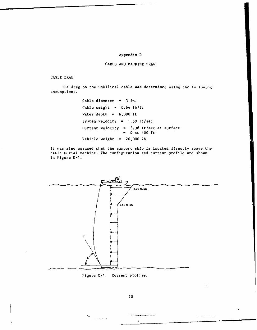
Appendix D
CABLE AND MACHINE DRAG
CABLE DRAG
The drag on the umbilical cable was determined using the followingassumptions.
Cable diameter - 3 in.
Cable weight - 0.64 lb/ft
Water depth - 6,000 ft
System velocity - 1.69 ft/sec
Current velocity - 3.38 ft/sec at surface
= 0 at 300 ft
Vehicle weight = 20,000 lb
It was also assumed that the support ship is located directly above thecable burial machine. The configuration and current profile are shownin Figure D-1.
T
0
Figure D-1. Current profile.
70

A computer analysis, was performed to determine tension T and angle
as a function of cable length. The results, which are accurate to 420%due to problem simplifications made to accommodate the computer, areplotted in Figures D-2 and D-3. Of particular interest is the horizontal
component of tens.on T, since the burier propulsion system must providethis force in adetion to the other forces acting on the burier. TableD-i shows the. vertical and horizontal components of T as a function ofcable length. A cable length of 6,500 feet and a horizontal componentof 3,400 pounds were selected as representative values for concept
evaluation.
Table D-1. Vertical and Horizontal Components
of T as a Function of Cable Length
Cable Length- T V H
(ft) (deg) i (lb) (lb) (lb)
6,100 75 11,400 11,000 3,0006,200 63.5 8,500 7,600 3,800
6,300 57.4 [ 7,100 6,000 3,8006,400 54.2 6,200 5,000 3,6006,500 52 5,500 4,300 3,4006,600 50.2 5,100 3,900 3,3006,700 48.8 4,800 3,600 3,2006,800 47.7 4,600 3,400 3,1006,900 46.8 4,400 3,200 3,0007,000 46 4,300 3,100 3,000
V - T sinO11 - T coso
BURIAL MACHINE DRAG
Assume that the machine frontal dimensions are width - 12 feet andheight - 10 feet. Then,
w/h - 1.2
* ''DESADE'' by R. A. Skop, Naval Research Laboratory.
71
vr

75
740
cable angle
454
6(.00 6,200 6.4-00 6,600 6.800 7 .(444
(:abl I cngth (f4)
Figure D)-2. Umbilical length versus angle.
6j4K) ff
cable tension
4,00
6,000 6.200 6.400 6.600 6,800 7.(XO
Cable Length (ft)
Figure D-3. Umbilical length versus tension.
72
f - _ _

From Reference 46, C d' 1.2
PW 2F D - A v
where C D =drag coefficient
Ow . mass density of seawaterW 2
A = frontal area = 120 ft
V = velocity = 1.69 ft/sec
Then,
F D (1.2)(1/2)(2 Ib-sec 2 /ft 4 )(120 ft 2)(1.69 ft/sec) 2
F =411 lbID
73

DISTRIBUTION LIST
SNI . lt , 1oVt A i v;t ICA 1)~ i'.
1 12 Defense Documentation Cent er
KAI\IC I 10 Naval Facilities Engineurir
Command
FKNI 6 6 NAVFAC Engineering Field Divi~ion-
FKN5 9 9 Public Works Centers
FA25 I I Public Works Center
6 6 RDT&E Liaison Officers at NAVFACEngineering Field Divisions
220 222 CC, Special Distribution List No.11 for persons and activitiesinterested in reports on OceanEngineering
74