concepcion - installation manual, start-up … · fan motor type psc psc psc compressor type rotary...
TRANSCRIPT
1
CONTENTS: Physical Data and Dimensions Introduction Refrigerant Line Sizing Field Piping Works Piping Connections Refrigerant Charging Wiring Procedure
Service Guides and General Notes Cleaning Piping Connections Electrical Connections Operation and Startup Required Piping Size Unit Wiring Diagrams
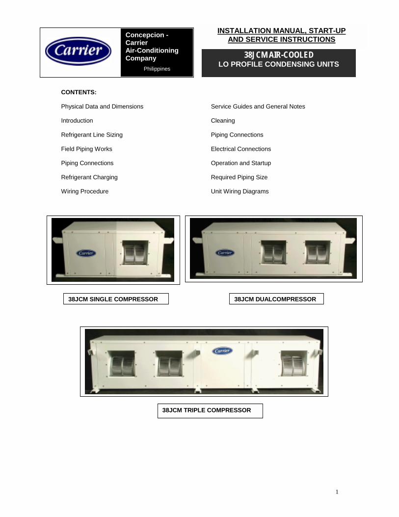
38JCM DUALCOMPRESSOR 38JCM SINGLE COMPRESSOR
Concepcion - Carrier Air-Conditioning Company
Philippines
38JCM AIR-COOLED LO PROFILE CONDENSING UNITS
INSTALLATION MANUAL, START-UP AND SERVICE INSTRUCTIONS
38JCM TRIPLE COMPRESSOR

2
PHYSICAL DATA AND DIMENSIONS:
Table 1
1 COMPRESSOR SERIES MODEL 38JCM112 38JCM118 38JCM124
DIMENSIONS ( MM ) Height, MM 470 Width, MM 1120 Depth, MM 565
CONDENSER COIL Copper Tube / Aluminum Fin No. of Rows 3 3.5 3.5 Fins per inch 17 17 17
Area, Sq. Meter 0.329 0.329 0.329 ELECTRICAL DATA
Fan Motor Size , Hp 1/2.26 Fan Motor FLA 1.73 1.73 1.73 Fan Motor Type PSC PSC PSC
Compressor Type ROTARY Compressor FLA 4.9 7 10.6 Protective Device Internal Protector
Electrical Power Supply 208-230 Volts/1 phase/60 Hertz PIPING CONNECTION Flare Type
Suction Tube OD, Inch 1/2 1/2 5/8 Liquid Tube OD, Inch 1/ 4 1/4 3/8
SAFETY CONSIDERATION Installation and servicing of air conditioning equipmentcan be hazardous due to system pressure and electricalcomponents. Only trained and qualified servicepersonnel should install repair or service air conditioningequipment. Observe precautions in the literature, tagsand labels attached to the unit and other safety codes. Wear safety glasses and gloves. Use quenching clothand have fire extinguisher available for all brazingoperations.
RECEIVING 38JCM condensing units are shipped individually andprotected with Styrofoam pads and plastic shrink wrap.Do not roll, throw or drop the unit. This may damage unitwhen you do so. Always store unit in upright position asthe symbol shown.
PROTECTION Protect unit from damage caused by job site debris. Do not allow dust, debris and water get into the unit. These will damage unit’s component and unit performance will be affected.
INSPECTION Check the shipment against shipping list and remove unit protective covering. If the unit has been damaged, file claim with Transportation Company and immediately notify Concepcion-Carrier.
ELECTRIC SHOCK HAZARD Before installing or servicing system always switch off main power supply. There may be more than one disconnect switch. Electric shock can cause personal injury.

3
Table 2 2 COMPRESSOR SERIES
MODEL 38JCM1812 38JCM1818 38JCM2412 38JCM2418
DIMENSIONS: ( MM )
Height, MM 470
Width, MM 1595
Depth, MM 565
CONDENSER COIL: Copper Tube/Aluminum Fin
No. of Rows 3.5 3.5 3.5 3.5
Fins per inch 17 17 17 17
Area, Sq. Meter 0.526 0.526 0.526 0.526
ELECTRICAL DATA
Fan Motor Size, Hp 1/2
Fan Motor FLA 2.34 2.34 2.34 2.34
Fan Motor Type PSC
Compressor Type ROTARY (18000) (12000) (18000) (18000) (24000) (12000) (24000) (18000)
Compressor FLA (each) 7 4.9 7 7 10.6 4.9 10.6 7
Protective Device Internal Protector
Electrical Power Supply 208-230Volts/1 phase/60 Hertz
PIPING CONNECTIONS Flare Type
Table 3 3 COMPRESSOR SERIES
MODEL 38JCM181224 38JCM181824 38JCM181818 38JCM181218 38JCM181212
DIMENSIONS: ( MM ) Height, MM 470
Width, MM 2108
Depth, MM 695
Copper Tube/Aluminum Fin CONDENSER COIL:
1812 24 1818 24 1818 18 1812 18 1812 12
No. of Rows 3.5 3.5 3.5 3.5 3.5 3.5 3.5 3.5 3.5 3
Fins per inch 17 17 17 17 17
Area, Sq. Meter 0.526 0.329 0.526 0.329 0.526 0.329 0.526 0.329 0.526 0.329
ELECTRICAL DATA Fan Motor Size, Hp
1/2 1/2.26 1/2 1/2.26 1/2 1/2.26 1/2 1/2.26 1/2 1/2.26
Fan Motor FLA 2.34 1.73 2.34 1.73 2.34 1.73 2.34 1.73 2.34 1.73
Fan Motor Type PSC PSC PSC PSC PSC
Compressor Type ROTARY
Protective Device Internal Protector
Electrical Power Supply 208-230Volts/1 phase/60 Hertz PIPING CONNECTIONS Flare Type

4
INTRODUCTION: The 38JCM models are designed for use with 1, 2 or 3 indoor fan coil units depending on the number of compressors. Each compressor has its own independent control & power wirings but all the compressors share a common fan drive system. Each compressor also has its own refrigerant pipe lines. Install these condensing units either thru-the-wall, outdoors on a slab or on the roof. When installing units, allow sufficient space for airflow clearance, wiring, refrigerant piping and servicing units. REFRIGERANT LINE SIZING Follow the recommendation given under UNIT DATA for the selection of tube OD. Incorrect sizing would either result in excessive pressure drop or unsatisfactory oil return. The cooling coils should be connected as close as possible. Both liquid and suction line lengths should be less than 15 meters. Condensing units should not be more than 5 meters above or below the evaporator coils except for 24K (please refer to Figure 3). Run refrigerant tubes as directly as possible, avoiding unnecessary turns and pipe bends. Condensing unit may be connected to evaporator sections using field-supplied tubing of refrigerant grade, correct size and condition. Suspend refrigerant tubes so they do not transmit vibration to structure. Leave some slack in refrigerant tubes between structure and unit to absorb vibration. Longer piping runs reduce cooling capacity. See Table 3 for percentage of system cooling capacity reduction in relation to piping length. Table 3: REDUCTION IN CAPACITY VS. INCREASE IN PIPE LENGTH
PIPING LENGTH (ONE WAY) Actual Unit Capacity (BTUH) 7.5m 10m 15m
12 k 0 % 1.7 % 3.2 % 18 k 0 % 1.6 % 3.4 % 24 k 0 % 1.5 % 3.6 %
FIELD PIPING WORKS Do not bury more than 36 in. of refrigerant pipe tubing in the ground. If more than 36 in. of tubing is buried, refrigerant can migrate to the colder buried section during extended periods of unit shutdown, causing refrigerant slugging and possible compressor damage at startup. If any tubing is buried at least six in., a vertical rise should be provided at the service valve. Also the buried line set should be run inside a chase or conduit. It is also recommended that a crankcase heater be installed in the unit. If either refrigerant tubing or indoor coil is exposed to atmospheric conditions for longer than 5 minutes, it must be evacuated to 1000 microns to eliminate contamination and moisture in the system. PIPING CONNECTION •
Run refrigerant tubes as directly as possible and avoid turns and bends.
• Align tubing flare with service valve connection and tighten the nut with the correct torque.
• Refer to Table 3 for vertical and horizontal piping length.
Figure3. MAXIMUM ALLOWABLE PIPING LENGTHS AND ELEVATION DIFFERENCE
Unit Capacity (BTU/H)
MAX HEIGHT H – m (ft)
MAX LENGTH H– m (ft)
12 k 5 (16.5) 15 (50)
18 k 5 (16.5) 20 (65)
24 k 7.5 (16.5) 20 (65)
AIR PURGE Air does not function as refrigerant because it can not be condensed in the condenser. Air and moisture remaining in the system have undesirable effects. Therefore, they must be purged out completely. AIR PURGING PROCEDURE 1. Remove the blind caps of the liquid valve. 2. Loosen the valve stem of the liquid valve by 900 for 5
seconds with a hexagonal key wrench. Then close the valve stem quickly.
3. Push the valve core of the suction valve. 4. Stop pushing as soon as the hissing stops. 5. Open the liquid valve for about 3 seconds, and then close
quickly to check for gas leak. 6. After checking for gas leaks, open the liquid and suction
valves all the way. 7. Re-install the blind caps. REFRIGERANT CHARGING The 38JCM units are all Factory charged suitable for 7.5 meters length of interconnecting pipe. Charge adjustment is required on system more than the standard 7.5 meter pipe length. Each refrigerant circuit is equipped with a service valve on its suction and liquid line. This enables charging and pressure measurement to be done. Use a good vacuum pump in the evacuation to obtain a clean system. Do not overcharge the system. This will cause liquid flood-back. One recommended charging method is the superheat method. The correct amount of charge is critical.

5
EXPANSION SYSTEM The 38JCM units are factory equipped with a system for refrigerant gas expansion device called capillary tube. COMPLETE ELECTRICAL CONNECTIONS Each circuit has its own control and power wiring except for the fan motor which is common to all. The compressor motor is protected by its internal protector. The fan motor starts together with one or more compressors. For all circuits, any interruption to the load will initiate a 3-minute delay and prevent the compressor from being re-energized until the normal delay period has elapsed. The wiring circuits are wired such that the fan motor is de-energized when all the compressors cycle off. Since many of the components in each of the 38JCM models are identical, careful wiring is important. POWER - Unit is factory wired for voltage shown on the name plate. Provide adequate fused disconnect switch within sight of unit, readily accessible, but out of reach of children.
Provision for locking switch open (off) is advisable to prevent power from being turned on while unit is being serviced. Route power wires through opening in the unit side panel knock-out holes and connect into control box. Unit must be grounded.
WIRING PROCEDURE 1. This unit is factory wired for voltage shown on the unit
nameplate. 2. Remove top cover of the outdoor unit and connect wires
firmly to the terminal block (s). Secure control box cover back once wiring connection is tested and completed.
3. All switches, fuses and field wiring must carry unit running ampere and must comply with local code requirements.
4. Unit factory wiring diagram is shown on the inside of the service cover.
Note: Operation of unit on improper line voltage constitutes abuse and void Carrier Warranty. Do not install unit in system where voltage may fluctuate above or below permissible limits SERVICE GUIDES CAUTION: Disconnect electric power from main switch before performing any maintenance or service units. 1. General Notes: When performing any routine service operations or doing specific repairs to the components, motors, fans and other components, all drain passages should be thoroughly cleaned. Inside painted surfaces should be cleaned with mineral spirits to remove grease. Check indoor and outdoor units to see that all controls are functioning correctly and the operation of the units is normal. Be sure that the tubing does not vibrate against the side of the indoor or outdoor unit. Ensure that the indoor unit is leveled so that condensate drains correctly from it. When disconnecting power or control wiring, it is recommended that identification tags be attached to the wires to facilitate rapid and correct re-assembly.
Before disconnecting any capacitor it is necessary that the capacitor be discharged by shorting its terminals with an insulated screwdriver. Check fans to see they are centered in the fan housings, correctly positioned and tight on shafts. After replacing fans, check clearance of wheel to housing prior to operation. Shield the coils with cardboard from the inside prior to removing interior components. 2. Cleaning The single most important item affecting your air conditioning effectiveness is its cleanliness. The following items require regular attention (Caution: disconnect electric power from main switch before performing any maintenance item.) Paint any parts that show evidence of rust with a good rust resistant paint. The rubber mounting grommets for the compressor in the outdoor unit should be replaced if they deteriorate. Check all the wiring for deterioration and electrical contacts for tightness and correction. PIPING CONNECTION Correct coupling of suction and liquid lines to every fan coil is essential. The same is true for the wiring. PIPING INSULATION Insulate both suction and liquid lines as per Fig. 4 since the unit is supplied with capillary tube as refrigerant control device. FIG. 4 PIPING INSULATION EVACUATION AND DEHYDRATION Evacuation is the most important part of the entire service procedure. The life and efficiency of the equipment is dependent upon the thoroughness exercised by the serviceman when evacuating air and moisture from the system. Air in the system causes high condensing temperature and pressure, resulting in increased power consumption and reduced system efficiency. Moisture chemically reacts with the refrigerant and oil thus forming corrosive hydrofluoric and hydrochloric acids which attacks motor windings and parts, causing early breakdown. After the system has been leak checked and proven leak free, connect now the vacuum pump and evacuate system to 29” Hg vacuum. It is advisable to connect both vacuum pump hose to the high-side and low-side of the system.

6
FINAL LEAK TEST After the unit has been properly evacuated and charged, a halogen leak detector is recommended to be used but water-soap solution is acceptable in absence of the electronic leak detector. All piping within the condensing unit, evaporator, and interconnecting tubing should be checked for leaks. If a leak is detected, the refrigerant should be recovered before repairing the leak. Please join us saving our planet by complying with Clean Air Act. ELECTRICAL CONNECTIONS POWER WIRING � Unit is factory wired for voltage shown on nameplate. � Provide adequate fused disconnect switch within
sight of unit, readily accessible but out of reach of children.
� Provision for locking switch open (off) is advisable to prevent power from being turned on while unit is installed or serviced.
� Disconnect switch, fuses and field wiring must comply with local codes. Size the wire as per electrical specification shown in CCAC Service Installer Blue Book.
� Use terminal marked ‘L’ and ‘N’ for 230V-1Ph power supply. See respective wiring diagram shown on the preceding pages.
CONTROL CIRCUIT WIRING All final electrical connections must be made with a length of flexible conduit to minimize vibration and sound transmission to the building. Field wiring must comply with local and national fire, safety and electrical codes. OPERATION AND START-UP PRELIMINARY CHECKS
Before operating the unit, be sure the following are in order: 1. All wiring connections are correct and tight. 2. All barriers, covers and panels are in place. 3. Electrical power supply conforms to the unit’s
requirement. 4. Piping system is flushed and clean. 5. All joints are leak tested and leak free. 6. All valves are opened. TO START UNIT 1. Field disconnect switch is closed. 2. Set room temperature below ambient setting. 3. Compressor will start once time delay is elapsed
(approximately 3 minutes) 4. Operate unit for 30 minutes, then check system
refrigerant charge.
PIPING SIZES and MAXIMUM LENGTH
MODEL (38JCM) (12000)
(18000)
(24000)
GAS LINE (OD), In 1/2 1/2 5/8
LIQUID LINE (OD), In 1/4 1/4 3/8
MAXIMUM PPING LENGTH, (M)
15 20 20
MAXIMUM VERTICAL SEPARATION, (M) 5 5 7.5
Consult the unit wiring diagram located on the inside of the access panel to ensure proper electrical hookup. Route power supply and signal wires through opening in unit’s side panel to their respective terminals. Check all electrical connections, including factory wiring within the unit and make sure all connections are tight.
WARNING
TO AVOID POSSIBLE INJURY OR DEATH DUE TO ELECTRICAL SHOCK, OPEN THE POWER SUPPLY DISCONNECT SWITCH (SWITCH-OFF) AND SECURE IT IN AN OPEN POSITION DURING INSTALLATION. USE LOCK-OUT AND TAG-OUT SECURITY LOCKS!
CAUTION THE CONTROL VOLTAGE FROM THE FAN COIL UNIT MUST BE OF 230V. DO NOT CONNECT THE POWER SUPPLY TO THE SIGNAL

7
INSTALLATION DETAILS
8
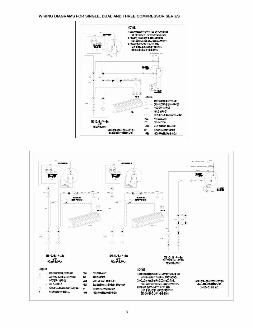
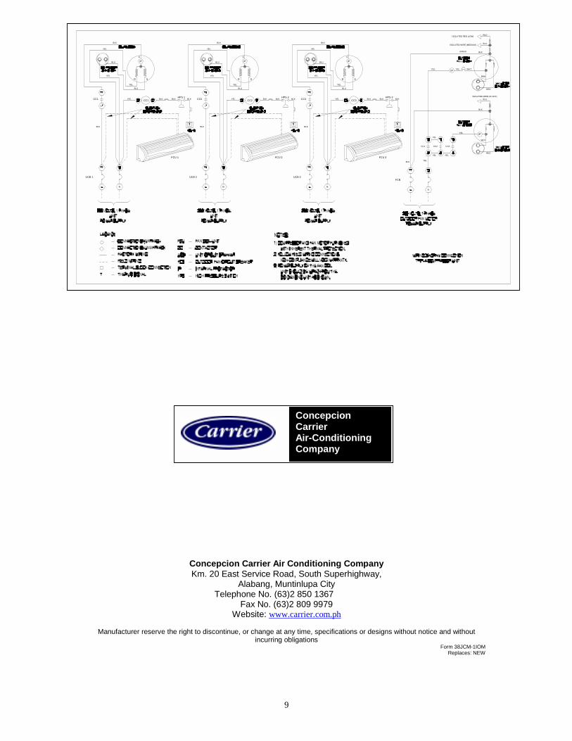
WIRING DIAGRAMS FOR SINGLE, DUAL AND THREE COMPRESSOR SERIES
YEL IP
YEL
CC CC
BLK
UCB
HPSBLKCC BLK BLK
WHT
RED
YEL
YEL
YEL
BLU
BLK
BLU
R S
C
IP
BLK
BLUISOLATED WIRE (IF ANY)
FCU 1
UCB 1 UCB 2
FCU 2
CC1
FCB
BLKYEL
CC2
YEL
BLKCC1
R
BLU
YEL
BLK
YEL
YEL
S
BLKCC1
BLK
YEL
BLU IP
C
IP
HPS 1BLK
BLK
CC2
RYEL
BLU
YEL
YEL
BLU
YEL
BLK
C
HPS 2
S
BLKBLKCC2 BLK
WHTYELIPYEL
YEL
BRN
BRN
ISOLATED RED (LOW)
ISOLATED WIRE (MEDIUM)
(HIGH) BLK
BLU
RED
9
Concepcion Carrier Air Conditioning Company Km. 20 East Service Road, South Superhighway,
Alabang, Muntinlupa City Telephone No. (63)2 850 1367
Fax No. (63)2 809 9979 Website: www.carrier.com.ph
Manufacturer reserve the right to discontinue, or change at any time, specifications or designs without notice and without
incurring obligations Form 38JCM-1IOM
Replaces: NEW
ConcepcionCarrier Air-Conditioning Company
BRN
RED
ISOLATED WIRE (IF ANY)BLK
FCU 1
YEL
CC1
UCB 1
R
BLU
YEL
YEL
BLK
S
BLKCC1
BLU
BLK
YEL
C
IP
BRNYELYEL
UCB 2
BLK
BLKHPS 1
CC2
YEL
R S
CC2YEL
BLU
FCU 2
UCB 3
BLKBLKBLKHPS 2
BLK
CC3
FCB
BLK
FCU 3
S
YEL
R
BLKCC3YEL
BLU
BLKBLKHPS 3
CC3CC1
YEL
CC2
YEL
YEL
YEL
BLU
BLK
WHT
IPYEL
YEL
C
IPBLU
BLK
BLU
BLK
YEL
C
IP
IP
ISOLATED WIRE (MEDIUM)
YEL
RED
BLU
WHT
BLK
YEL
ISOLATED RED (LOW)
(HIGH)