comsol notes - akshansh
TRANSCRIPT


DISCLAIMER: While the document has attempted to make the information as accurate as possible, the information on this document is for personal and/or educational use only and is provided in good faith without any express or implied warranty. There is no guarantee given as to the accuracy or currency of any individual items. The document does not accept responsibility for any loss or damage occasioned by use of the information contained and acknowledges credit of author(s) where ever due. While the document makes every effort to ensure the availability and integrity of its resources, it cannot guarantee that these will always be available, and/or free of any defects, including viruses. Users should take this into account when accessing the resources. All access and use is at the risk of the user and owner reserves that right to control or deny access. Information, notes, models, graph etc. provided about subjects, topics, units, courses and any other similar arrangements for course/paper, are an expression to facilitate ease of learning and dissemination of views/personal understanding and as such they are not to be taken as a firm offer or undertaking. The document reserves the right to discontinue or vary such subjects, topic, units, courses, or arrangements at any time without notice and to impose limitations on accessibility in any course.
COMSOL Multiphysics Notes, First Edition
Copyright © 2013 Akshansh
ALL RIGHTS RESERVED.
Presented by: Akshansh Chaudhary Graduate of BITS Pilani, Dubai Campus Batch of 2011
Course content by: Dr. Anand Kumar Then Faculty, BITS Pilani, Dubai Campus
Layout design by: AC Creations © 2013
The course content was prepared during Spring, 2014. More content available at: www.Akshansh.weebly.com

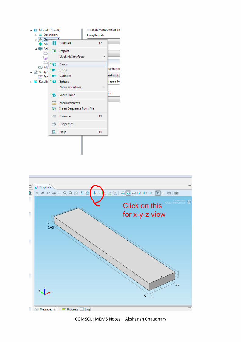
Point Load Starting Interface -
Idea: Starting with cantelever Design a beam Leave the second side free of the beam
COMSOL: MEMS Notes – Akshansh Chaudhary

COMSOL: MEMS Notes – Akshansh Chaudhary

Next, select the measurement unit and other dimensions as given
COMSOL: MEMS Notes – Akshansh Chaudhary
COMSOL: MEMS Notes – Akshansh Chaudhary

COMSOL: MEMS Notes – Akshansh Chaudhary

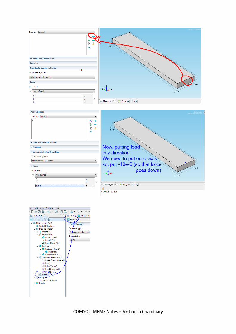
Now, rotate the model and select one of the sides of length 5. Next, click on + button on the toolbox at the side.
COMSOL: MEMS Notes – Akshansh Chaudhary

COMSOL: MEMS Notes – Akshansh Chaudhary
COMSOL: MEMS Notes – Akshansh Chaudhary

This makes the diagram colored A strip tells the amount of stress and the details on that. Which figure has the max stress - we get to know from the figure
COMSOL: MEMS Notes – Akshansh Chaudhary

We find that the free end has maximum displacement
COMSOL: MEMS Notes – Akshansh Chaudhary

Note: We can know the properties of material we are using. Here we are using copper. So, click on it to see its properties.
Save the file.
COMSOL: MEMS Notes – Akshansh Chaudhary

Boundary LOAD
COMSOL: MEMS Notes – Akshansh Chaudhary

COMSOL: MEMS Notes – Akshansh Chaudhary

COMSOL: MEMS Notes – Akshansh Chaudhary

COMSOL: MEMS Notes – Akshansh Chaudhary

The total displacement is, as shown in the diagram.
COMSOL: MEMS Notes – Akshansh Chaudhary

By observation, it is lesser, as compared to point load. Save the file again.
COMSOL: MEMS Notes – Akshansh Chaudhary

Changes Now,
Change 1 Changing the values in geometry and seeing the deflection in that case.
COMSOL: MEMS Notes – Akshansh Chaudhary

Change 2 Now, change the thickness (height) of the model and for small values, check which is the smallest value, giving the maximum deflection and is able to tolerate as well.
COMSOL: MEMS Notes – Akshansh Chaudhary

EXTRA Displaying moving details of how the figure was getting modified
COMSOL: MEMS Notes – Akshansh Chaudhary

Joule Heating Method for Actuator We want to see how the temperature varies in our work piece when it is made as per the specifications. Idea : S1) Make a 3d Figure. For that, make a workplane under geometry tab. Then, add rectangles as per the dimension. Next, go to Work plane option and click on Extrude. That makes it 3D. S2) Add Material. Go to Material library and select Poly-Si.
MEMS>Semiconductor>Poly-Si S3) Select Joule Heating in Physics.
Model 1 - Right Click> Add Physics Heat Transfer> Electromagnetic Heating> Joule Heating (jh)
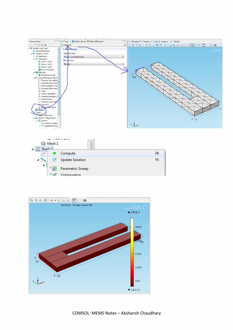
S4) Now, start adding the properties to the work piece. S5) Do meshing of the object S6) Compute
Objective - To model Joule heating of a micro actuator using COMSOL Joule heating module
COMSOL: MEMS Notes – Akshansh Chaudhary

COMSOL: MEMS Notes – Akshansh Chaudhary

COMSOL: MEMS Notes – Akshansh Chaudhary

COMSOL: MEMS Notes – Akshansh Chaudhary

COMSOL: MEMS Notes – Akshansh Chaudhary

Then, go to Union and click Buld all. Next, Extrude the 2D image we made.
COMSOL: MEMS Notes – Akshansh Chaudhary

COMSOL: MEMS Notes – Akshansh Chaudhary

COMSOL: MEMS Notes – Akshansh Chaudhary

COMSOL: MEMS Notes – Akshansh Chaudhary

COMSOL: MEMS Notes – Akshansh Chaudhary

COMSOL: MEMS Notes – Akshansh Chaudhary
COMSOL: MEMS Notes – Akshansh Chaudhary

COMSOL: MEMS Notes – Akshansh Chaudhary

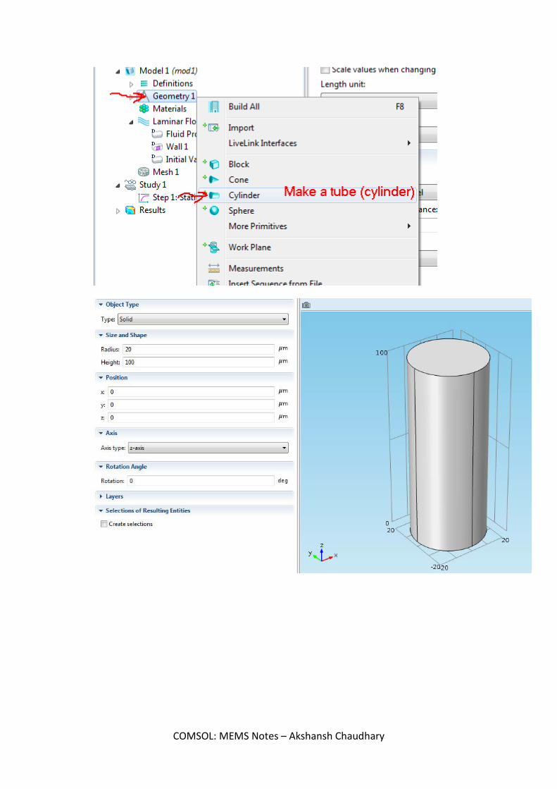
Analysis of Circular diaphragm in micro pressure sensor and find the deflection We have to make a disk (or a thin cylinder) Now, apply pressure at its top and analyze the figure we get. Initial steps - 3D > Solid Mechanics (solid) > Stationary Select cylinder in Geometry and take the following dimensions -
Now, Select the material - Poly-Si Next, Click on Solid Mechanics. Right click and add - Fixed Constraint.
COMSOL: MEMS Notes – Akshansh Chaudhary

Now, once the base is set, we need to add load over the top or bottom. For that use Boundary load option.
COMSOL: MEMS Notes – Akshansh Chaudhary

Next, go to Mesh and Build All. Finally, Study 1 > Compute.
COMSOL: MEMS Notes – Akshansh Chaudhary

Now, to see the total displacement, Stress> Surface
Then, Click on Plot.
COMSOL: MEMS Notes – Akshansh Chaudhary

Similarly, the dimensions of the disk can be changed and we can see for different values. Done!
COMSOL: MEMS Notes – Akshansh Chaudhary

Making a Capacitor
COMSOL: MEMS Notes – Akshansh Chaudhary

COMSOL: MEMS Notes – Akshansh Chaudhary

COMSOL: MEMS Notes – Akshansh Chaudhary

COMSOL: MEMS Notes – Akshansh Chaudhary

COMSOL: MEMS Notes – Akshansh Chaudhary

COMSOL: MEMS Notes – Akshansh Chaudhary

COMSOL: MEMS Notes – Akshansh Chaudhary

COMSOL: MEMS Notes – Akshansh Chaudhary

COMSOL: MEMS Notes – Akshansh Chaudhary

COMSOL: MEMS Notes – Akshansh Chaudhary

Microgripper
COMSOL: MEMS Notes – Akshansh Chaudhary

COMSOL: MEMS Notes – Akshansh Chaudhary

COMSOL: MEMS Notes – Akshansh Chaudhary

COMSOL: MEMS Notes – Akshansh Chaudhary

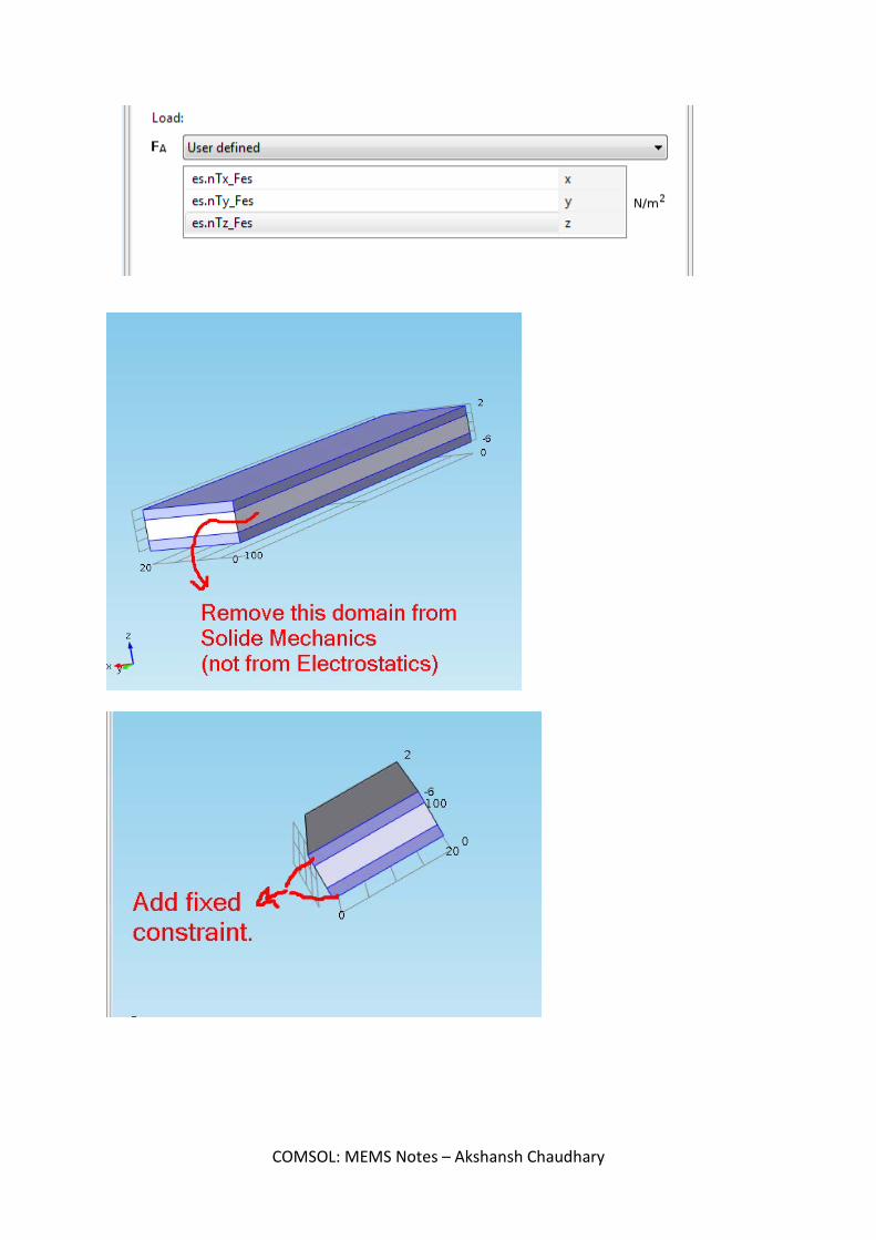
Note: Force also has to be given only at the top and bottom. Not in the middle.
COMSOL: MEMS Notes – Akshansh Chaudhary
COMSOL: MEMS Notes – Akshansh Chaudhary

In Force calculation, the force has to be added in the specified part:
COMSOL: MEMS Notes – Akshansh Chaudhary

COMSOL: MEMS Notes – Akshansh Chaudhary

COMSOL: MEMS Notes – Akshansh Chaudhary

MICROGRIPPER: Scale Changing Micro gripper was used in Micro scale. Now, change it to different scales and measure the difference in deflection. We see that the only change needs to be done in the scaling factor. The scaling needs to be increased to see the same effect of gripping.
Original Scale : um Case 1:
Changing scale to mm
Case 2:
Changing the scale to cm
COMSOL: MEMS Notes – Akshansh Chaudhary

Case 3:
Changing scale to inch
Note: Displacement is independent of scaling. OBSERVATION 1: Constant: • Material - Si (c )
Table 1: Shows the amount of scaling that needs to be done in order to get the gripping action at the corner. Dimension Scaling Displacement (m)
Mm 4e12 6.0617*10^-13
Cm 4e13 6.0614*10^-14
In 9e13 2.3865*10^-14 OBSERVATION 2: Now, keeping um as standard displacement, changing the values of voltage to get the same displacement at other scales. Constant: • Material: Silicon • Reference - um
o Scaling - 4e9 o Displacement - 6.0617*10^-10 m
COMSOL: MEMS Notes – Akshansh Chaudhary

Table 2: Shows the value of the voltage for each scale, giving the same displacement as in micrometer scale. Dimension Displacement (m) Voltage value (V)
Mm 6.0617*10^-13 5
6.0617*10^-11 50
1.3639*10^-10 75
6.053*10^-10 158
Cm 6.0614*10^-14 5
6.0617*10^-12 50
5.455*10^-11 150
6.0617*10^-10 500
In 2.3865*10^-14 5
9.546*10^-12 100
8.5914*10^-11 300
6.03333*10^-10 795 OBSERVATION 3: Now changing the material of the micro gripper and observing the displacement. Constant: • Dimension: um • Middle layer: Air
Table 3: Shows the displacement of the micro gripper with different materials. Material Displacement (m)
Si ( c ) 6.0617*10^-10
Poly-Si 5.1787*10^-10
Glass (quartz) 1.0616*10^-9
GaAs 1.189*10^-9
SiO2 1.1665*10^-9
COMSOL: MEMS Notes – Akshansh Chaudhary

Scaling Problem: We have a cylinder (tube) and fluid flowing through it. Now, when the dimensions of the tube is changed, note the pressure drop.
COMSOL: MEMS Notes – Akshansh Chaudhary
COMSOL: MEMS Notes – Akshansh Chaudhary

Surface option. (instead of Solid)
COMSOL: MEMS Notes – Akshansh Chaudhary

COMSOL: MEMS Notes – Akshansh Chaudhary

COMSOL: MEMS Notes – Akshansh Chaudhary
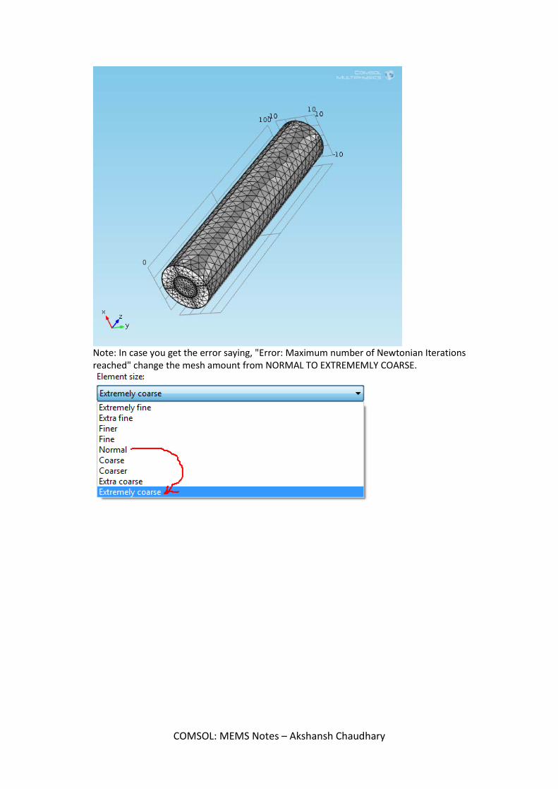
Note: In case you get the error saying, "Error: Maximum number of Newtonian Iterations reached" change the mesh amount from NORMAL TO EXTREMEMLY COARSE.
COMSOL: MEMS Notes – Akshansh Chaudhary

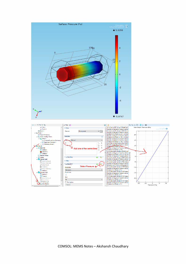
Radius is 5um
COMSOL: MEMS Notes – Akshansh Chaudhary

On changing the dimensions to 10um and 20um, we have this pressure. (it decreases, as expected) Radius is doubled (10um now) So, by formula, Pressure is inversely proportional to the square of radius. So, as radius is doubled, pressure is becoming 1/4 times.
COMSOL: MEMS Notes – Akshansh Chaudhary
COMSOL: MEMS Notes – Akshansh Chaudhary

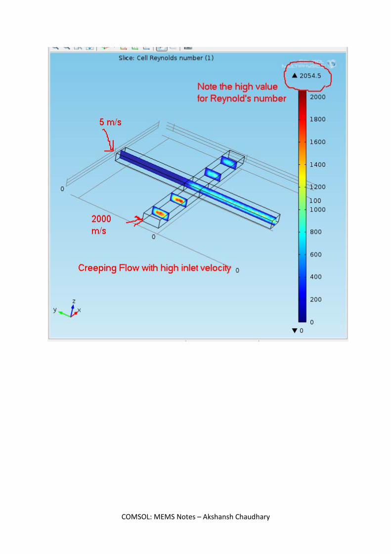
MICRO MIXER Model - 3D Physics - Laminar Flow Property - Stationary Make the model.
COMSOL: MEMS Notes – Akshansh Chaudhary

COMSOL: MEMS Notes – Akshansh Chaudhary

COMSOL: MEMS Notes – Akshansh Chaudhary

COMSOL: MEMS Notes – Akshansh Chaudhary

COMSOL: MEMS Notes – Akshansh Chaudhary

COMSOL: MEMS Notes – Akshansh Chaudhary

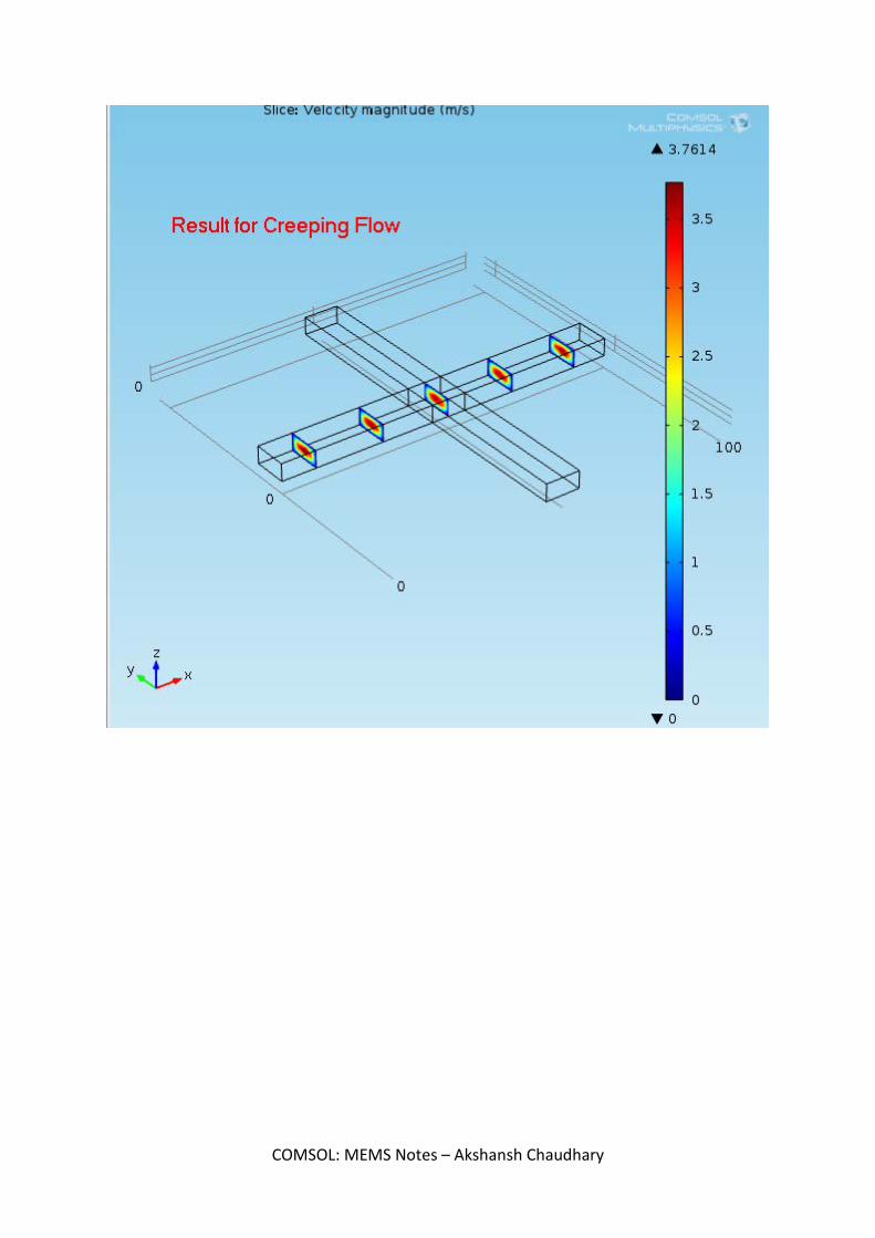
ONLY CREEPING FLOW
COMSOL: MEMS Notes – Akshansh Chaudhary

COMSOL: MEMS Notes – Akshansh Chaudhary
COMSOL: MEMS Notes – Akshansh Chaudhary

ONE FLOW LAMINAR, ONE FLOW CREEPING
COMSOL: MEMS Notes – Akshansh Chaudhary

COMSOL: MEMS Notes – Akshansh Chaudhary
COMSOL: MEMS Notes – Akshansh Chaudhary

USING TWO FLUIDS, WATER AND ETHANOL
COMSOL: MEMS Notes – Akshansh Chaudhary