computer systems organization · computer systems organization primary memory today memory cells...
TRANSCRIPT
Computer Systems Organization
Computer Systems OrganizationWolfgang Schreiner
Research Institute for Symbolic Computation (RISC-Linz)
Johannes Kepler University
http://www.risc.uni-linz.ac.at/people/schreine
Wolfgang Schreiner RISC-Linz
Computer Systems Organization
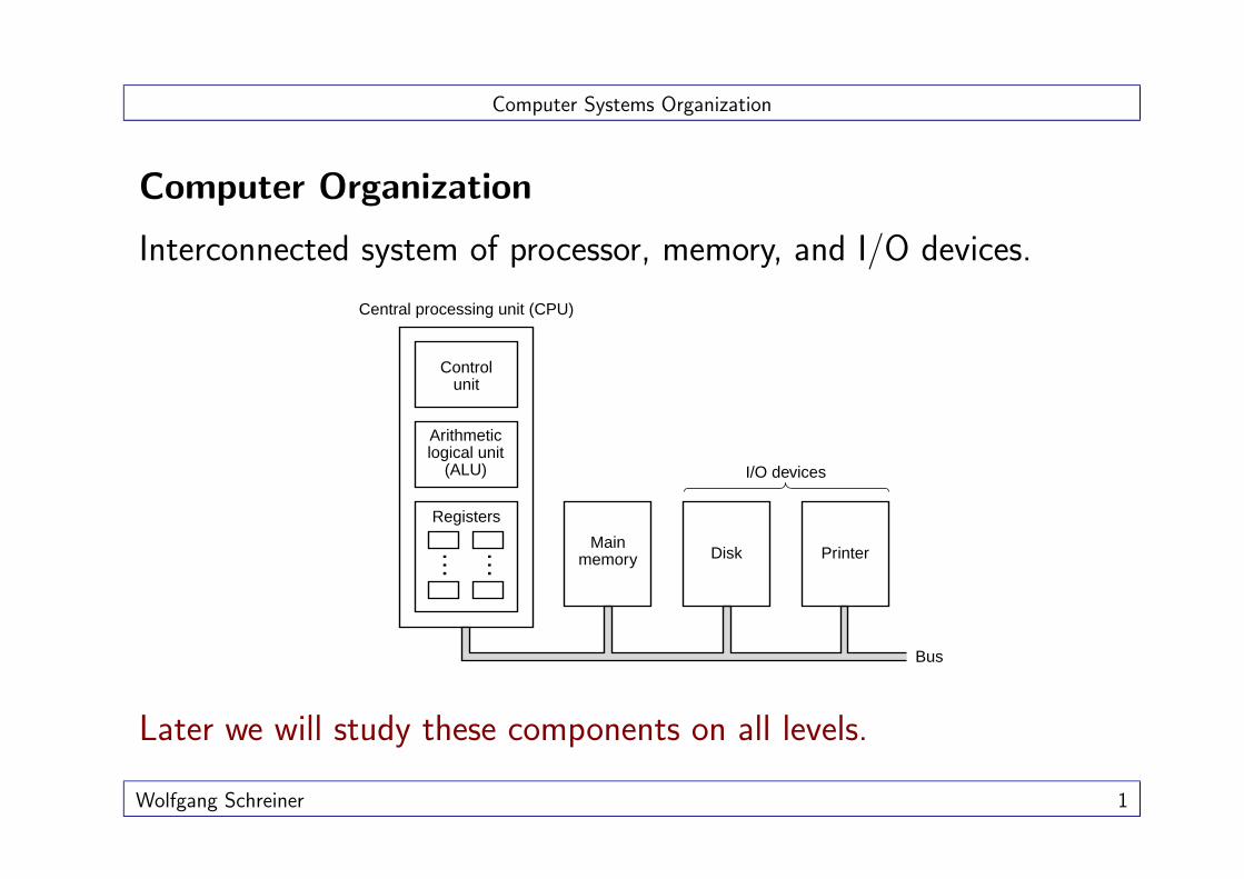
Computer Organization
Interconnected system of processor, memory, and I/O devices.
Central processing unit (CPU)
Control unit
Arithmetic logical unit
(ALU)
Registers
Main memory Disk Printer
Bus
I/O devices
… …Later we will study these components on all levels.
Wolfgang Schreiner 1

Computer Systems Organization
Example
A modern Personal Computer (PC) in 2001 may consist of
• a 933 MHz Pentium III processor,
• 256 MB RAM,
• a 30 GB hard disk,
• a keyboard and a mouse,
• a floppy disk drive,
• a 40x speed CD-ROM drive,
• a 19” monitor with 1280× 1024 pixels resolution,
• a 56 Kbit Modem,
• a 100 Mbit Ethernet card.
The last six items are I/O devices.
Wolfgang Schreiner 2

Computer Systems Organization
Processor
Wolfgang Schreiner 3

Computer Systems Organization
Processor
• Components are connected by a bus.– Collection of parallel wires.
– Transmits address, data, and control signals.
• Central component is the CPU.– Central Processing Unit.
– Executes program stored in main memory.
∗ Fetches its instructions.
∗ Examines them.
∗ Executes them one after another.
The CPU is the “brain” of the computer.
Wolfgang Schreiner 4

Computer Systems Organization
CPU Organization
CPU is composed of several distinct parts.
• Control unit.– Fetches instructions and determines their type.
• Arithmetic logic unit:– Performs operations needed to carry out instructions.
– Example: integer addition (+), boolean conjunction (∧).
• Registers:– Small high-speed memory to store temporary results and certain control information.
– All registers have same size and can hold one number up to some maximum size.
– There are general purpose registers and registers for special use.
– Program Counter (PC): address of the next instruction to be fetched for execution.
– Instruction Register (IR): instruction currently being executed.
Wolfgang Schreiner 5

Computer Systems Organization
Data Path
ALU and registered connected by several buses.
A + B
A + B
A
A
B
B
Registers
ALU input register
ALU output register
ALU
ALU input bus
• Registers feed into ALU inputregisters A and B.– Hold ALU input while ALU is computing.
• ALU performs operation andyields result in output register.– Content can be stored back into a register.
– Register content can be stored in memory.
Data path cycle is core of CPU.
Wolfgang Schreiner 6

Computer Systems Organization
Instruction Execution
CPU executes instruction in series of small steps.
1. Fetch the next instruction from memory into the instruction register.
2. Change the program counter to point to the following instruction.
3. Determine the type of the instruction just fetched.
4. If the instruction uses a word in memory, determine where it is.
5. Fetch the word, if needed, into a CPU register.
6. Execute the instruction.
7. Go to step 1 to begin executing the followin instruction.
Fetch-decode-execute cycle.
Wolfgang Schreiner 7

Computer Systems Organization
Interpreter for Simple Computer
static int PC, AC, instr, type, loc, data;
static boolean run_bit = true;
// interpret program stored in memory starting at start_address
public static void interpret(int memory[], int start_address) {
PC = starting_address;
while (run_bit) {
instr = memory[PC]; // fetch next instruction
PC = PC+1; // increment program counter
type = getType(instr); // determine instruction type
loc = getLoc(instr, type); // locate data (-1, if none)
if (loc >= 0) data = memory[loc]; // fetch data
execute(type, data); // execute instruction
}
}
Wolfgang Schreiner 8

Computer Systems Organization
RISC versus CISC
• Since the late 1950s, instructions were interpreted.– Bugs could be easily fixed.
– New instructions could be added at minimal cost.
– More and more complex instruction sets emerged (CISC: 200–300 instructions).
• In the 1980s, a radically different concept emerged.– Patterson and Sequin (Berkeley): RISC design → SPARC architecture.
– Hennessey (Stanford): MIPS architecture.
– Simple instructions that could be quickly issued (started) and executed in hardware.
– Small instruction sets (about 50 instructions).
• Today: CISC processors with a RISC core.– Simple instructions are executed in a single cycle (common instructions are fast).
– More complex instructions are interpreted as usual (backward compatibility).
– Example: Intel Pentium line.
Wolfgang Schreiner 9

Computer Systems Organization
Modern Design Principles
• All common instructions are directly executed in hardware.– CISC instructions are broken into sequences of RISC instructions.
•Maximize the rate at which instructions are issued.– Less important how long execution of instruction takes.
• Instructions should be easy to decode.– Instructions have fixed length, regular layout, small number of fields.
•Only loads and stores should reference memory.– Operands of all other operations come from and return to registers.
• Provide plenty of registers.– Memory access is slow ⇒ 32 registers or more.
Moreover: instruction-level parallelism (pipelining, superscalar).
Wolfgang Schreiner 10

Computer Systems Organization
Pipelining
Divide instruction into sequence of small steps.
(a)
(b)
S1:
S2:
S3:
S4:
S5:
1 2 3 4 5 6 7 8 9
1 2 3 4 5 6 7 8
1 2 3 4 5 6 7
1 2 3 4 5 6
1 2 3 4 5
1 2 3 4 5 6 7 8 9
Time
…
S1 S2 S3 S4 S5
Instruction fetch unit
Instruction decode
unit
Operand fetch unit
Instruction execution
unit
Write back unit
Processor operates at cycle time of the longest step.
Wolfgang Schreiner 11

Computer Systems Organization
Superscalar Architectures
Have multiple functional units that operate independently in parallel.
S2 S3 S5
Instruction decode
unit
Operand fetch unit
LOADWrite back unit
S1
Instruction fetch unit
S4
Floating point
STORE
ALU
ALU
S3 stage must issue instructions fast enougth to utilize S4 units.
Wolfgang Schreiner 12

Computer Systems Organization
Processor Clock
Execution is driven by a high-frequency processor clock.
• Example:– 933 MHz processor (MHz = million Herz).
– Clock beats 933 million times per second.
– Clock speed doubles every 18 months (Moore’s law).
• Clock drives execution of instructions:– Instruction may take 1, 2, 3, . . . clock cycles.
– 933 Mhz: at most 933 million instructions can be performed.
– Different processors have instructions of different power.
∗ 550 MHz PowerPC processor may be faster than 933 Mhz Pentium III processor.
Clock frequency is not a direct measure for performance.
Wolfgang Schreiner 13

Computer Systems Organization
Primary Memory
Wolfgang Schreiner 14

Computer Systems Organization
Primary Memory
•Memory consists of a number of cells.– Each cell can hold k bits, i.e., 2k values.
• Each cell can be referenced by an address.– Number from 0 to 2n − 1.
• Each cell can be independently read or written.– RAM: random access memory.
Data stored in memory cells
48024803480448054806480748084809481048114812
AdressesLarge valuesstored acrossmultiple cells
Memory is volatile: content is lost when power is switched off.Wolfgang Schreiner 15
Computer Systems Organization
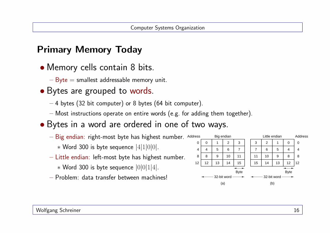
Primary Memory Today
•Memory cells contain 8 bits.– Byte = smallest addressable memory unit.
• Bytes are grouped to words.– 4 bytes (32 bit computer) or 8 bytes (64 bit computer).
– Most instructions operate on entire words (e.g. for adding them together).
• Bytes in a word are ordered in one of two ways.– Big endian: right-most byte has highest number.
∗ Word 300 is byte sequence |4|1|0|0|.– Little endian: left-most byte has highest number.
∗ Word 300 is byte sequence |0|0|1|4|.– Problem: data transfer between machines!
Address AddressBig endian
Byte
00
(a)
44
88
1212
0
4
8
12
1
5
9
13
2
6
10
14
3
7
11
15
32-bit word
Little endian
Byte
3
(b)
7
11
15
2
6
10
14
1
5
9
13
0
4
8
12
32-bit word
Wolfgang Schreiner 16

Computer Systems Organization
Memory Units
Hierarchy of units of memory size.
Unit Symbol Bytes
byte 20 = 1 byte
kilobyte KB 210 = 1024 bytes
megabyte MB 220 = 1024 KB
gigabyte GB 230 = 1024 MB
terabyte TB 240 = 1024 GB
Multiplication factor to next unit is 1024 = 210.
Wolfgang Schreiner 17

Computer Systems Organization
Error-Correcting Codes
Computer memories make occasionally errors.
• Errors use error-detecting or error-correcting codes.– r extra bits are added to each memory word with with m data bits.
– When a word is read from memory, bits are checked to see if error has occurred.
• Hamming distance (Hamming, 1950).– Minimum number of bits in which two codewords differ.
– 11110001 and 00110000 have Hamming distance 3.
– With Hamming distance d, d single-bit errors are required to convert one word into the other.
• Construct n-bit codeword where n = m + r.– 2n codewords can be formed.
– 2m codewords are legal.
– If computer encounters illegal codeword, it knows that error has occurred.
Wolfgang Schreiner 18

Computer Systems Organization
Code Properties
Hamming distance of a code is minimum distance of two codewords.
•Detect d single-bit errors.– Errors must not change one valid codeword into another.
– Hamming distance d + 1 is required.
• Correct d single-bit errors.– Codewords must be so far apart that error word is closest to original codeword.
– Hamming distance 2d + 1 is required.
• Example: parity bit code.– Add single bit such that total number of 1 bits is even.
– Each single-bit error generates codeword with wrong parity.
– Hamming distance 2, single-bit errors can be detected.
Wolfgang Schreiner 19

Computer Systems Organization
Cache Memories
• CPUs have always been faster as memories.– When CPU issues a memory request, it has to wait for many cycles.
• Problem is not technology but economics.– Memories that are as fast as CPUs have to be located on CPU chip.
– Chip area is limited and costly.
• Cache: small amount of fast memory.– Most heavily used memory words are kept in cache.
– CPU first looks in cache; if word is not there, CPU reads word from memory.
Cache
Bus
Main memory
CPU
Wolfgang Schreiner 20

Computer Systems Organization
Cache Performance
• Locality principle: basis of cache operation.– In any short time interval, only a small fraction of total memory is used.
– When a word is referenced for the first time, it is brougth from memory to cache.
– The next time the word is used, it can be accessed quickly.
– 1 reference to slow memory, k references to fast cache.
• Cache lines: units of memory transfer.– When cache miss occurs, entire sequence of words is loaded from memory.
– Typical cache line is 64 bytes (16 words a 32 bit).
– Reference to address 260 loads cache line 256–319.
– Chances are high that also other words in cache line will be used in near future.
• Today CPUs have multiple caches.– Primary cache on CPU chip.
– Larger secondary cache in same package as CPU chip.
Wolfgang Schreiner 21

Computer Systems Organization
Memory Packaging and Types
Group of chips is mounted on a circuit board and sold as a unit.
• SIMM: single inline memory module.– Single row of connectors on one side of the board (72 connectors delivering 32 bits).
– For instance: eight chips with 4 MB each.
4-MB memory
chip
Connector
•DIMM: dual inline memory module.– Two rows of connectors on each side (168 connectors delivering 64 bits).
Error detection and correction are omitted for PC memory.
Wolfgang Schreiner 22

Computer Systems Organization
Secondary Memory
Wolfgang Schreiner 23

Computer Systems Organization
Secondary Memory
Main memory is always too small.
Registers
Main memory
Cache
Tape
Magnetic disk
Optical disk
Non-volatile storage: keeps data without power.
Wolfgang Schreiner 24

Computer Systems Organization
Magnetic Disk (Harddisk)
Magnetic medium: bits are represented by small magnetized particles.
Much larger but also much slower than primary memory.
Wolfgang Schreiner 25

Computer Systems Organization
Harddisk Organization
•Multiple spinning platters are organized as a stack.
• Read/write head passes over platter.
Surface 2Surface 1
Surface 0
Read/write head (1 per surface)
Direction of arm motion Surface 3
Surface 5
Surface 4
Surface 7
Surface 6
All read/write heads are moved by the same arm.
Wolfgang Schreiner 26

Computer Systems Organization
Platter Organization
Aluminium platter has magnetizable coating.
• Read/write head floats on a cushion of air over its surface.– Writing: current flowing through head magnetizes surface beneath.
– Reading: magnetized surface induces current in head.
– As platter rotates, stream of bits can be read or written.
– Disk track: circular sequence of bits written in one rotation.
Track width is 5–10 microns
Width of 1 bit is 0.1 to 0.2 microns
Direction of arm motion
Disk arm
Read/write head
Intersector gap
Direction of di�sk
�r� otation
4096 data b� i� ts
Preamble
E �
C C
4096 data bits
Preamble
E C C
�1 sector
Wolfgang Schreiner 27

Computer Systems Organization
Data Organization
• Each track is divided into sectors of fixed size.– Preamble that allows head to be synchronized before reading or writing.
– 512 data bytes (typically).
– Error-correcting code (ECC).
– Intersector gap.
• Formatted capacity: size of data areas (only).
• Two densities define storage capacity.
1. Radial density: number of tracks per radial cm (800–2000).
2. Linear bit densities: number of bits per track cm (up to 100.000).
• Cylinder: set of tracks at a given radial position.– All read/write heads can access one cylinder at a time.
Wolfgang Schreiner 28

Computer Systems Organization
Disk Performance
Performance is determined by various factors.
• Seek time: time to move the arm to the right radial position.– 5–15 ms average seek time (between random tracks).
• Rotational delay: time until desired sector rotates under head.– Average delay is half a rotation.
– 7200 rpm (rotations per minute): 4 ms.
• Transfer time: time to read sector.– Depends on linear density and rotation speed.
– 20 MB/s: 25 µs to read a 512 byte sector.
• Seek time and rotational delay dominate transfer time.– Burst rate: data rate once the head is over the first data bit.
– Sustained rate is much smaller than burst rate.
Wolfgang Schreiner 29

Computer Systems Organization
Performance Comparison
Memory access times have different orders of magnitude.
Operation Clock CyclesCPU instruction 1–3Register access 1Cache access 1Main memory access 10Disk seek time 10.000.000
Magnetic disk is one million times slower than main memory.
Wolfgang Schreiner 30

Computer Systems Organization
Disk Controllers
A CPU built into the disk controls its operation.
• Accepts commands from the main processor.– READ, WRITE, FORMAT.
• Controls arm motion.
•Detects and corrects errors.
• Converts bytes read from memory into serial bit stream.
• Cache sector reads and buffer sector writes.
• Remaps bad sectors by spare sectors.
Disk controller frees CPU from low-level details of operation.
Wolfgang Schreiner 31

Computer Systems Organization
Disk Controller Interfaces
• (E)IDE: (Extended) Integrated Drive Electronics.– IDE: sectors are addressed by head, cylinder, sector numbers (512 MB limit).
– EIDE: up to 224 consecutively addressed sectors (LBA: Logical Block Addressing).
– ANSI standard: ATAPI (AT Attachment Packet Interface).
– Technology for cheap PC harddisks, floppy drives, CD-ROM drives, tape drives, . . .
• SCSI: Small Computer Systems Interface.– Bus to which controller and chain of up to seven devices can be attached.
– All devices can run at the same time.
– SCSI-1: 5 MHz clock rate, 8 bit data transfer.
– Fast SCSI (10 MHz bus), Ultra SCSI (20 MHz), Ultra2 SCSI (40 MHz).
– Wide SCSI: 16 bit transfer.
– 5–80 MB/s transfer rate (Ultra2 Wide-SCSI).
– Higher performance but more expansive than EIDE/ATAPI.
Wolfgang Schreiner 32

Computer Systems Organization
RAID
Redundant Array of Inexpensive Disks.
• Box of disks can be operated as a single disk.– RAID controller presents single disk to operating system.
– Typically: SCSI disks operated by RAID SCSI controller.
• RAID levels define data distribution/redundance properties.– RAID 0: strips of k sectors are distributed round robin across disks (single disk).
– RAID 1: strips are mirrored on two sets of disks (fault recovery).
– RAID 2: bits are distributed across disks (data rate).
– RAID 3: simplified version of RAID 2, parity bit written to extra drive.
– RAID 4: like RAID 0, with parity bits written to extra drive (fault recovery).
– RAID 5: like RAID 0, with parity bits distributed across drives (fault recovery).
Also software implementations of RAID (Linux).
Wolfgang Schreiner 33

Computer Systems Organization
RAID
P16-19 Strip 16 Strip 17 Strip 18
Strip 12 P12-15 Strip 13 Strip 14
(a)
(b)
(c)
(d)
(e)
(f)
RAID level 0
Strip 8
Strip 4
Strip 0
Strip 9
Strip 5
Strip 1
Strip 10
Strip 6
Strip 2
RAID level 2
Strip 11
Strip 7
Strip 3
Strip 8
Strip 4
Strip 0
Strip 9
Strip 5
Strip 1
Strip 10
Strip 6
Strip 2
Strip 11
Strip 7
Strip 3
Strip 8
Strip 4
Strip 0
Strip 9
Strip 5
Strip 1
Strip 10
Strip 6
Strip 2
Strip 11
Strip 7
Strip 3
Bit 1 Bit 2 Bit 3 Bit 4 Bit 5 Bit 6
RAID level 1
Bit 7
Bit 1 Bit 2 Bit 3 Bit 4
Strip 8
Strip 4
Strip 0
Strip 9
Strip 5
Strip 1
Strip 10
Strip 6
Strip 2
Strip 11
Strip 7
Strip 3
Strip 8
Strip 4
Strip 0
Strip 9
Strip 5
Strip 1
P8-11
Strip 6
Strip 2
Strip 10
P4-7
Strip 3
Strip 19
Strip 15
RAID level 3
RAID level 4
RAID level 5
Parity
P8-11
P4-7
P0-3
Strip 11
Strip 7
P0-3
Wolfgang Schreiner 34
Computer Systems Organization
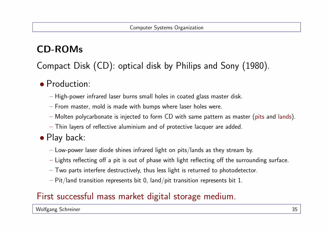
CD-ROMs
Compact Disk (CD): optical disk by Philips and Sony (1980).
• Production:– High-power infrared laser burns small holes in coated glass master disk.
– From master, mold is made with bumps where laser holes were.
– Molten polycarbonate is injected to form CD with same pattern as master (pits and lands).
– Thin layers of reflective aluminium and of protective lacquer are added.
• Play back:– Low-power laser diode shines infrared light on pits/lands as they stream by.
– Lights reflecting off a pit is out of phase with light reflecting off the surrounding surface.
– Two parts interfere destructively, thus less light is returned to photodetector.
– Pit/land transition represents bit 0, land/pit transition represents bit 1.
First successful mass market digital storage medium.Wolfgang Schreiner 35

Computer Systems Organization
CD-ROM Physical Layout
Spiral groove
Pit
Land
2K block of user data
• Pits/lands are written in a single continuous spiral inside-out.– 22.188 revolutions (600 per mm), 5.6 km length.
• Pits/lands must stream by at constant velocity.– Rotation rate of CD is reduced as reading head moves inside-out.
– 530 rpm – 200 rpm.
Wolfgang Schreiner 36

Computer Systems Organization
CD-ROM Logical Layout
• 1984: CD-ROM (CD - Read Only Memory).– Data standard which is physically compatible with audio CDs.
– Sector of 98 frames with 42 symbols of 14 bits each (1 byte + ECC).
Preamble
Bytes 16
Data
2048 288
ECCMode 1 sector
(2352 bytes)
Frames of 588 bits, each containing 24 data bytes
Symbols of 14 bits each
42 Symbols make 1 frame
98 Frames make 1 sector
…
…
• 1986: multimedia CD-ROMs.– Audio, video, data interleaved in same sector.
• Finally: ISO 9660 filesystem.Wolfgang Schreiner 37

Computer Systems Organization
CD-Recordables
• 1989: CD-Rs (recordable CDs).– Gold used instead of aluminium for reflective layer.
– Layer of dye inserted between polycarbonate and reflective layer.
– When high-power laser hits dye, it creates a dark spot which is interpreted as a pit.Printed label
Protective lacquerReflective gold layer
layer
Substrate
Direction of motion Lens
Photodetector Prism
Infrared laser diode
Dark spot in the dye layer burned by laser when writing1.2 mm
Dye
Polycarbonate
• CD-Rs can be written incrementally.– Track: group of consecutive sectors written at once (without interruption).
– Multi-session: multiple VTOCs (Volume Table of Contents).
Wolfgang Schreiner 38

Computer Systems Organization
CD-ROM/R Characteristics
•Data transfer: 153 KB/s.– Single speed drive.
– Today: up to 80× drives.
• Seek time: several 100s of ms.– No match for hard disk.
– High streaming rates, low random access rates.
• Capacity: 74 minutes of music.– 650 MB of data.
– Higher capacities available.
Primary purpose is data transfer and backups.
Wolfgang Schreiner 39

Computer Systems Organization
DVD
Digital Versatile Disk.
• Same physical design as CDs.– Smaller pits, tighter spiral, red laser.
– 4.7 GB data capacity, 1.4 MB/s data transfer (single speed).
– DVD drives can read also CD-ROMs.
• Further formats.– Capacity: Dual layer (8.5 GB), double sided (9.4 GB), double sided dual layer (17 GB).
– Rewriting: DVD-R, DVD-RW, DVD+RW (let the battle begin!)Polycarbonate substrate 1
Polycarbonate substrate 2
Semireflective layer
Semireflective layer
Aluminum reflector
Aluminum reflector
0.6 mm Single-sided
disk
0.6 mm Single-sided
disk
Adhesive layer
Wolfgang Schreiner 40

Computer Systems Organization
Input/Output Devices
Wolfgang Schreiner 41

Computer Systems Organization
Physical Computer Structure
Metal box with with the motherboard at bottom.
SCSI controller
Sound card
Modem
Edge connectorCard cage
I/O boards can be connected to the motherboard.
Wolfgang Schreiner 42

Computer Systems Organization
Motherboard
CPU, DIMM slots, support chips, bus, I/O slots.
Wolfgang Schreiner 43

Computer Systems Organization
Logical Computer StructureMonitor
Keyboard Floppy disk drive
Hard disk drive
Hard disk
controller
Floppy disk
controller
Keyboard controller
Video controllerMemoryCPU
Bus
• Each I/O device has a controller which contains the electronics.– Typically contained on a board plugged into a free slot (video controller).
– Sometimes contained on the board itself (keyboard controller).
– Connects to device by a cable attached to a connector on the back of the box.
Wolfgang Schreiner 44

Computer Systems Organization
Video Controller
•Monitor is passive device controlled by video card.– Active device connected to system bus (or special graphics bus).
– Holds in local memory digital image.
– Transfers it pixel by pixel to monitor for display.
– Refresh rate e.g. 80 Hz, data transfer: 80× 2560 KB = 200 MB per second!
Wolfgang Schreiner 45

Computer Systems Organization
Controller Operation
Controller controls I/O device and handles bus access for it.
• Takes command from CPU and executes it.– Disk controller: issues commands to drive to read data from a particular track and sector.
• Controller returns result to computer memory.– DMA (Direct Memory Access): controller can access memory without CPU intervention.
– When finished, controller causes an interrupt in the CPU.
– CPU suspends current program and executes an interrupt handler.
– Interrupt handler informs operating system that I/O has finished.
– Afterwards, CPU continues with suspended program.
• Bus access controlled by bus arbiter.– Chip which decides which device may access the bus.
– Usually I/O devices are given preference over CPU.
Wolfgang Schreiner 46

Computer Systems Organization
Modern PC StructureMemory bus
CPU PCI bridge
SCSI controller
SCSI disk
Network controller
Video controller
Printer controller
Sound card ModemISA
bridge
SCSI scanner
Main memorySCSI
bus
PCI bus
ISA bus
cache
PCI (Peripheral Component Interconnect) is the most popular bustechnology today.
Wolfgang Schreiner 47

Computer Systems Organization
Computer Monitors
• Typical characteristics:– 19” monitor (US inch = 2.54 cm, diagonal size).
– Resolution: 1280 × 1024 pixels (picture units).
– 16 bit graphics: a pixel may have 216 = 65536 colors.
– Information content: 1280× 1024× 16/8 bytes = 2560 KB.
• Pixel consists of 3 color elements.– RGB: red, green, blue.
– Control of combination/brightnesses.
•Dominant technologies:– CRT (Cathode Ray Tube).
– LCD (Liquid Crystal Display)
(a)(b)
y
z
Rear glass plate
Liquid crystal
Rear electrode
Rear polaroid
Front glass plate
Front electrode
Front polaroid
Bright
Dark
Light source
Notebook computer
������
����
��
Wolfgang Schreiner 48

Computer Systems Organization
Other I/O Devices
• Keyboard and mouse.– Interactive input devices.
– Connected to controllers on main board.
– Signals (key pressed, mouse moved) transferred to controller.
– Controller notifies processor to handle request.
• Laser printer.– Output device with local processor and memory.
– Controlled by printer programming language (e.g. PostScript).
– Computer constructs this program and sends it to printer.
– Printers paint image on electrically charged drum to which toner powder sticks.
– Print resulution measured in dpi (dots per inch); good quality ≥ 300 dpi.
– Color laser printers overlay images in subtractive primary colors and black (CYMK).
Laser Rotating octagonal mirror
Drum sprayed and charged
Light beam strikes drum
TonerScraperDischarger
Drum
Blank paper
Heated rollers
Stacked output
Wolfgang Schreiner 49

Computer Systems Organization
Network Devices
Computers connected in various ways.
•Modem (modulator/demodulator)– Converts digital information to analog signals transferred via phone lines.
– 56 Kbit/s (KBit = 1000 bit).
• ADSL (Asynchronous Digital Subscriber Line)– Conventional phone lines, special end devices.
– Download speeds: 512 KBit/s and more (upload: 64 Kbit/s).
• Ethernet– Most prominent technology for Local Area Networks (LANs).
– Copper wires used as buses.
– 10–100 Mbit/s (FastEthernet), 1 Gbit/s (GigaEthernet).
Wolfgang Schreiner 50

Computer Systems Organization
Modulation Principles
(a)
(b)
(c)
(d)
Vol
tage
Time
V1
V20 1 0 0 1 0 1 1 0 0 0 1 0 0
High amplitude
Low amplitude
High frequency
Low frequency
Phase change
Modulation by amplitude, frequency, phase.
Wolfgang Schreiner 51