computer science technical report tr-11-06 june 7,...
TRANSCRIPT

Computer Science Technical Report
TR-11-06
June 7, 2011
Joe Hays, Adrian Sandu, Corina Sandu, Dennis Hong
“Parametric Design Optimization of Uncertain Ordinary
Differential Equation Systems”
Center for Vehicle Systems and Safety
Computer Science Department & Department of Mechanical
Engineering
Virginia Polytechnic Institute and State University
Blacksburg, VA 24061
Phone: (540)-231-2193
Fax: (540)-231-9218
Email: [email protected]
Web: http://www.eprints.cs.vt.edu

Hays, Sandu, Sandu, Hong 6/7/2011 1
Parametric Design Optimization of Uncertain Ordinary Differential Equation Systems
Joe Hays
Mechanical Engineering Virginia Tech
Blacksburg, VA 24061
Adrian Sandu
Computational Science Laboratory Computer Science Department
Virginia Tech Blacksburg, VA 24061
Corina Sandu
Advanced Vehicle Dynamics Laboratory Mechanical Engineering
Virginia Tech Blacksburg, VA 24061
Dennis Hong
Robotics and Mechanisms Laboratory Mechanical Engineering
Virginia Tech Blacksburg, VA 24061
Abstract
This work presents a novel optimal design framework that treats uncertain dynamical systems described by ordinary differential equations.
Uncertainty in multibody dynamical systems comes from various sources, such as: system parameters, initial conditions, sensor and actuator noise,
and external forcing. The inclusion of uncertainty in design is of paramount practical importance because all real-life systems are affected by it.
Designs that ignore uncertainty often lead to poor robustness and suboptimal performance. In this work uncertainties are modeled using Generalized
Polynomial Chaos and are solved quantitatively using a least-square collocation method. The uncertainty statistics are explicitly included in the
optimization process. Systems that are nonlinear, have active constraints, or opposing design objectives are shown to benefit from the new
framework. Specifically, using a constraint-based multi-objective formulation, the direct treatment of uncertainties during the optimization process is
shown to shift, or off-set, the resulting Pareto optimal trade-off curve.
A nonlinear vehicle suspension design problem, subject to parametric uncertainty, illustrates the capability of the new framework to produce an
optimal design that accounts for the entire family of systems within the associated probability space.
Keywords: Design Optimization, Dynamic Optimization, Nonlinear Programming, Multi-Objective Optimization, Multibody
Dynamics, Uncertainty Quantification, Generalized Polynomial Chaos

Hays, Sandu, Sandu, Hong 6/7/2011 2
List of Variables (Nomenclature)
Independent variables Time Random event
General , Non-bolded variables generally indicate a scalar quantity , Bolded lower case variables are vectors, upper case variables are matrices Random variable Bottom right index generally indicates a state (with occasional exceptions). Top right index generally indicates a stochastic coefficient, or mode. Bottom left index generally associates to a specific collocation point. , Top left annotations indicate if a given variable is actuated or unactuated. The four major variable annotations Transpose , Partial derivative notations , # Matrix inverse and pseudo inverse , Lower and upper bounds on , Expected value, or mean, of , Variance of !", Standard Deviation of #$%, !&' Infimum and supremum of
Indexes & dimensions $( ∈ ℕ Number of degrees-of-freedom (DOF) $+, ∈ ℕ Number of generalized coordinates, where $+, ≥ $(, dependent on kinematic representation of rotation. $. ∈ ℕ Number of states $/ ∈ ℕ Number of parameters $ ∈ ℕ Number of input wrenches, 0 ∈ ℝ23 $4 ∈ ℕ Number of outputs, 5 ∈ ℝ26 '4 ∈ ℕ Polynomial order $7 ∈ ℕ Number of multidimensional basis terms $,/ ∈ ℕ Number of collocation points
Dynamics 8 ∈ ℝ29: Independent generalized coordinates 8; , 8< Rates and accelerations of generalized coordinates = ∈ ℝ2> Generalized velocities =; Generalized accelerations 8? = 8A , =? = =A Initial conditions B ∈ ℝ2C×2C Kinematic mapping matrix relating rates of generalized coordinates to generalized velocities E ∈ ℝ2F Uncertain parameters 0 ∈ ℝ23 Input wrenches G ∈ ℝ2C×2C Square inertia matrix H ∈ ℝ2C Centrifugal, gyroscopic and Coriolis terms J ∈ ℝ2C Generalized gravitational and joint forces K Differential operator 5 ∈ ℝ26 System outputs L ∈ ℝ26 Output operator
Uncertainty Quantification Ω Random event sample space N Joint probability density function O ∈ ℝ/6PQ Single dimensional basis terms Ψ ∈ ℝ2S Multidimensional basis terms T, T ∈ ℝ2:F Kth collocation point , ∈ ℝ2:F Kth intermediate variable of the ith state representing expanded quantity U ∈ ℝ2S×2:F Collocation matrix
Dynamic Optimization minY Optimization objective through manipulation of Y Y List of manipulated variables J Scalar objective function

Hays, Sandu, Sandu, Hong 6/7/2011 3
w Scalarlization weights for the individual input wrench contributions \ Inequality constraints (typically bounding constraints) Standard deviation scaling parameters
1 INTRODUCTION
1.1 MOTIVATION
Design engineers cannot quantify exactly every aspect of a given system. These uncertainties frequently create difficulties in accomplishing
design goals and can lead to poor robustness and suboptimal performance. Tools that facilitate the analysis and characterization of the effects of
uncertainties enable designers to develop more robustly performing systems. The need to analyze the effects of uncertainty is particularly acute when
designing dynamical systems. Ultimately, if a robust system design is to be achieved, uncertainties must be accounted for up-front during the design
process.
This work presents a novel parametric optimal design framework that treats uncertain dynamical systems described by linear or nonlinear
ordinary differential equations (ODEs). System uncertainties, such as parameters, initial conditions, sensor/actuator noise, or forcing functions, are
modeled using Generalized Polynomial Chaos (gPC) and are solved quantitatively using a least-square collocation method (LSCM). The
computational efficiencies gained by gPC and LSCM enable the inclusion of uncertainty statistics in the optimization process.
Specifically, this work presents the new framework in both a nonlinear programming (NLP) and Directed Search (DS) optimization setting. The
authors have found that the benefits of treating uncertainty during the parametric design optimization process are most evident when active
constraints are present; therefore, particular attention is given to its use in a constraint-based formulation of multi-objective optimization (cMOO).
These benefits are illustrated in an optimal vehicle suspension design case-study where the opposing performance criteria related to passenger ride
comfort, suspension operating displacement, and road holding are simultaneously accounted for.
The author’s prior work related to the motion planning of uncertain dynamical systems for fully-actuated and under-actuated systems was
presented in [1-4].
1.2 STATE OF THE ART IN DYNAMIC DESIGN OPTIMIZATION AND UNCERTAINTY QUANTIFICATION
In the following, a review of the literature is presented where works related to dynamic design optimization and uncertainty quantification are
specifically covered.
1.2.1 Dynamic Design Optimization Many different formulations and solver techniques are presented in the literature for approaching system design through dynamic optimization.
The selected case-study to showcase the new design framework of this paper is related to the optimal design of vehicle suspension systems; therefore,
particular preference is given to the review of related literature.
A common theme is found in most of the vehicle suspension optimal design related works, namely, proper design of a suspension needs to
address opposing design requirements related to passenger comfort (ride), suspension travel (rattle), and tire/road holding forces (holding). This
necessitates a multi-objective approach to the optimal design problem. For example, [5-11] all employed linear vehicle models to construct a Pareto
trade-off curve between the three referenced objectives.
Various methods were used to model the road input. A number of authors used stationary ergodic Gaussian inputs for linear models and used a
power-spectral density (PSD) transformation of the system’s linear frequency response [5, 6, 8, 11]. Additional attention was given to frequency
weighted power-spectrum inputs based on standards such as ISO 2631 [6, 8, 11, 12]. This approach directly accounts for uncertainty in the road input
of a linear system. Verros used the same Gaussian uncertain inputs for nonlinear quarter-car models through application of a Monte Carlo sampling
technique [6]. These are examples of continuous road irregularity inputs. Additional authors treated isolated road irregularities such as speed bumps
and potholes [12, 13].
Work related to active and semi-active suspension designs in addition to passive designs were presented in [7, 12-14]. The excellent work
presented by Jazar [10] and by Gobbi and co-workers [5] approached the problem analytically; where a majority of the literature used numerical
techniques showing a slight preference to DS-based (such as Genetic Algorithms [7, 9, 12]) versus NLP-based formulations [7, 13]. Also, adjacent
applications related to rail [8, 15, 16] and bicycle [17, 18] optimal suspension designs were approached in a similar fashion.
1.2.2 Monte Carlo Uncertainty Quantification The Monte Carlo (MC) method is considered the most robust method of uncertainty quantification. The method is quite simple; the probability
space of the system is randomly sampled $ times and statistical measures are determined from the ensemble [19]. MC provides a consistent error
convergence rate independent of the number of uncertainties. However, the convergence rate of 1/√$ is relatively slow.
Alternatively, quasi-Monte Carlo (QMC) methods deterministically sample the probability space with low-discrepancy sequences (LDS). QMC
is reported to show improved constant convergence, log $(/$, for relatively low dimensional problems when compared to MC [20, 21]; where " is
the number of dimensions.
1.2.3 Generalized Polynomial Chaos (gPC) Uncertainty Quantification Generalized Polynomial Chaos (gPC) is a relatively new method that is rapidly being accepted in diverse applications. It’s origins come from
early work by Wiener in the the 1930’s where he introduced the idea of homogenous chaoses [22]. His work made use of Gaussian distributions and
the Hermite orthogonal polynomials. Xiu and Karniadakis generalized the concept by expanding the list of supported probability distributions and
associated orthogonal polynomials [23, 24]; where the Galerkin Projection Method (GPM) was initially used. In [24-26], Xiu showed an initial
collocation method based on Lagrange interpolation. A number of Collocation point selection methods were also show including tensor products and
Smolyak sparse grids.

Hays, Sandu, Sandu, Hong 6/7/2011 4
In [27], Sandu et. al. introduced the least-squares collocation method (LSCM) and used the roots of the associated orthogonal polynomials in
selecting the sampling points. Cheng and Sandu showed the LSCM maintains the exponential convergence of GPM yet was superior in
computational speed in [28]; where the Hammersley LDS data set was the preferred method in selecting collocation points. Cheng and Sandu also
presented a modified time stepping mechanism where an approximate Jacobian was used when solving stiff systems.
1.2.4 Multi-Element gPC The accuracy of gPC deteriorates over time in long simulations and is dependent on continuity of the system. In an effort to address these two
concerns, Wan and Karniadakis developed multi-element gPC (MEgPC) [29, 30]. This method discretizes the probability space into non-overlapping
partitions. Within each partition the traditional single element gPC is performed. Summing element integrations provides a complete integration of
the full probability space. The algorithm presented adaptively partitioned the space based on estimates of error convergence. When an error estimate
deteriorated to a specified point the element was split. The initial work was developed for the GPM methodology using uniform distributions.
MEgPC was subsequently extended to arbitrary distributions in [31, 32]. Foo developed a collocation-based MEgPC in [33] and further extended the
method to support higher dimensions using ANOVA methods in [34].
As an alternative to MEgPC, Witteveen and Iaccarino developed a similar multi-element method based on gPC called the simplex elements
stochastic collocation (SESC) method. This method adaptively partitions the probability space using simplex elements coupled with Newton-Cotes
quadrature. Their method has shown an O(n) convergence as long as the approximating polynomial order is increased with the number of
uncertainties.
Another approach to addressing the long-term simulation accuracy of gPC was developed by Gerritsma and coworkers [35]; their approach
constructs a new set of orthogonal polynomials adaptively as the probability density function (PDF) evolves with time. Their work has shown that the
adaptively contrustructed polynomial basis allows for lower order approximations that have improved convergence for long-term simulations.
1.2.5 Recent Applications of gPC/MEgPC The origins of gPC come from thermal/fluid applications; however, its adoption in other areas continues to expand. Sandu and coworkers
introduced its application to multibody dynamical systems in [27, 28, 36-40]. Significant work has been done applying it as a foundational element in
parameter [23-26, 41-59] and state estimation [60, 61], as well as system identification [62]. Relatively recent work has applied gPC to both classical
and optimal control system design [41, 63, 64]. Also, MEgPC has been used applied to uncertainty quantification in power systems [65] and mobile
robots [66].
The structure of this paper is as follows. A very brief introduction into the parametric optimal design of deterministic dynamical systems is
reviewed in Section 2; Section 3 reviews the Generalized Polynomial Chaos methodology for uncertainty quantification; Section 4 introduces the
new framework for parametric optimal design of uncertain ODE-based systems; and finally, Section 5 illustrates the strengths of the new framework
through a cMOO vehicle suspension design case-study. Concluding remarks are found in Section 6.
2 PARAMETRIC OPTIMAL DESIGN OF DETERMINISTIC SYSTEMS The new framework presented in this work is not dependent on a specific EOM formulation; formulations such as Newtonian, Lagrangian,
Hamiltonian, and Geometric methodologies are all applicable. An Euler-Lagrange ODE formulation describes a multibody dynamical system [67,
68] by, Gc8, Ed=; + Hc8, =, Ed= + Jc8, =, Ed = Kc8, =, =; , Ed = 0 (1)
where 8 ∈ ℝ29: are the generalized coordinates with $+, ≥ $(; = ∈ ℝ2> are the generalized velocities and—using Newton’s dot notation—=; contains their time derivatives; E ∈ ℝ2F includes system parameters of interest; fc8, Ed ∈ ℝ2>×2> is the square inertia matrix; Hc8, =, Ed ∈ ℝ2>×2> includes centrifugal, gyroscopic, and Coriolis effects; Jc8, =, Ed ∈ ℝ2> are the generalized gravitational
and joint forces; and 0 ∈ ℝ23 are the $ applied wrenches (or torques). (For notational brevity, all future equations will drop the explicit time
dependence.)
The relationship between the time derivatives of the independent generalized coordinates and the generalized velocities is, 8; = B8, E= (2)
where B8, E is a skew-symmetric matrix that is a function of the selected kinematic representation (e.g., Euler Angles, Tait-Bryan Angles, Axis-
Angles, Euler Parameters, etc.) [3, 69, 70]. However, if (1) is formulated with independent generalized coordinates and the system has a fixed base,
as in [1, 2], then (2) becomes 8; = =.
The trajectory of the system is determined by solving (1)–(2) as an initial value problem, where 80 = 8A and =0 = =A. Also, the system
measured outputs are defined by, 5 = L8, 8; , E (3)
where 5 ∈ ℝ26 with $4 equal to the number of outputs.
Given (1)–(3), the NLP-based formulation of the deterministic optimal design problem can be described as,
min J = Jhij s. t. K8, =, =; , E = 0 8; = B8, E= 5 = L8, 8; , E \5, E, 0 ≤ ? 80 = 80, 8cod = 8pq
(4)

Hays, Sandu, Sandu, Hong 6/7/2011 5
8; 0 = 8; 0, 8; cod = 8; pq
where J = Jhij represents the design objective function; \ is the list of design constraints; is the list of optimization variables; and r80, 8; 0, 8cod, 8; cods are the system’s initial conditions (ICs) and optional terminal conditions (TCs).
The NLP defined in (4) may be approached from either a sequential nonlinear programming (SeqNLP), or from a simultaneous nonlinear
programming (SimNLP) perspective [71, 72]. (The literatures occasionally refers to the SeqNLP approach as partial discretization and to the
SimNLP as full discretization [73].) In the SeqNLP approach, the dynamical equations (1)–(3) remain as continuous functions that may be integrated
with standard off-the-shelf ODE solvers (such as Runge-Kutta). This yields a smaller optimization problem as only the optimization
search/manipulated variables are discretized. On the contrary, the SimNLP approach discretizes (1)–(3) over the trajectory of the system and treats
the complete set of equations as equality constraints for the NLP. The discretized state variables are added to to complete the full discretization.
The SimNLP has a much larger set of constraints and optimization variables than the SeqNLP approach, but, enjoys a more structured NLP that
typically experiences faster convergence.
The DS class of optimization solvers—techniques such as Genetic Algorithms, Differential Evolution, and Particle Swarm—typically only treat
unconstrained optimization problems. Therefore, all the design constraints in (4) need to be converted from hard constraints to soft constraints; where
hard constraints are explicitly defined as shown in (4), and constraints that are added to the definition of the objective function, J, are referred to as
soft constraints. This is accomplished by additional cost terms of the form
Jthuvwx = ∑ max 0, |, ~, 2:Q (5)
where $, represents the number of system constraints, and µ is a large constant. With a large µ, this relationship is analogous to an inequality like
penalizing term, meaning, if the constraint | is outside its bounds—or outside the feasible region—then it’s heavily penalized. When it’s within the
feasible region there is no penalty. Also, by squaring the max function its discontinuity is smoothed out; however, this is an optional feature and only
necessary for a solver that uses gradient information.
Once the constraints have been converted to penalty terms, equation (4) can be reformulated as the following unconstrained optimization problem
min J = Jhij + Jthuvwx s. t. Kc8, =, =; , Ed = 0 8; = Bc8, Ed= 5 = Lc8, 8; , Ed
(6)
Equation (6) is analogous to the SeqNLP in that it is dependent on the ODE integration of the implicit dynamics found in (1)–(3) and their associated
ICs.
Ultimately, the design task encoded in (4) and (6) is to determine what values of the manipulated variables minimize J. Design problems frequently have multiple objective terms defined in Jhij. Since the final cost function, J, ultimately needs to be a scalar value, a
weighted scalarization of the various terms in Jhij is commonly used.
Jhij = wQJQ + w J + ⋯ + wuJu (7)
The relative weighting of the multiple terms, wQ, w , … , wu, yields a trade-off relationship between the various objective terms. In other words,
there are an infinite set of optimal solutions—known as a Pareto optimal set—where each is uniquely defined by the scalarization weights. Problems
of this nature are frequently referred to as multi-objective optimization (MOO) problems.
A Pareto optimal set may also be found as active constraint boundaries are moved. For example, if a given output, Q, is bounded from above by, , we have the following constraint, Q ≤ . A Pareto set will be obtained from the optimal design for unique values of as long as the constraint is
active. Once the constraint becomes inactive the constraint has no influence on the optimal value. Occasionally, a MOO problem may be
appropriately rewritten such that extra objective terms, say J , … , Ju, are redefined as problem constraints. For example,
J − J ≤ 0, J − J ≤ 0⋮Ju − Ju ≤ 0, Ju − Ju ≤ 0 (8)
where J, Ju represents lower and upper bounds. In doing so, the Pareto set is now governed by the unique values of the bounds of the only the
active constraints. This reformulation of MOO will be referred to as a constrained multi-objective optimization (cMOO) problem. The cMOO
reformulation will be of particular significance in Section 4 where the new framework for the optimal design of uncertain dynamical systems is
presented.
The following section will briefly review Generalized Polynomial Chaos (gPC) which is the technique used for uncertainty quantification in the new
framework presented in Section 4.
3 GENERALIZED POLYNOMIAL CHAOS Generalized Polynomial Chaos (gPC), first introduced by Wiener [22], is an efficient method for analyzing the effects of uncertainties in second
order random processes [23]. This is accomplished by approximating a source of uncertainty, ~, with an infinite series of weighted orthogonal
polynomial bases called Polynomial Chaoses. Clearly, an infinite series is impractical; therefore, a truncated set of '4 + 1 terms is used with '4 ∈ ℕ
representing the order of the approximation. Or,
~ = ~O/6A (9)
Hays, Sandu, Sandu, Hong 6/7/2011 6
where ~ ∈ ℝ represent known stochastic coefficients; O ∈ ℝ represent individual single dimensional orthogonal basis terms (or modes); ∈ ℝ
is the associated random variable for ~ that maps the random event ∈ Ω, from the sample space, Ω, to the domain of the orthogonal polynomial
basis (e.g., : Ω → −1,1). Polynomial chaos basis functions are orthogonal with respect to the ensemble average inner product, ⟨O, O⟩ = OON"QQ = 0, for i≠j (10)
where N is the weighting function that is equal to the joint probability density function of the random variable . Also, ⟨Ψ , Ψ⟩ = 1, ∀ when
using normalized basis; standardized basis are constant and may be computed off-line for efficiency using (10).
Generalized Polynomial Chaos can be applied to multibody dynamical systems described by differential equations [27, 36]. The presence of
uncertainty in the system results in uncertain states. Therefore, the uncertain states can be approximated in a similar fashion as (9),
;; = ;Ψ2SA , # = 1 … $. (11)
where ; ∈ ℝ2S represent the gPC expansion coefficients for the #p state; and $7 ∈ ℕ represents the number of basis terms in the approximation.
It is instructive to notice how time and randomness are decoupled within a single term after the gPC expansion. Only the expansion coefficients are
dependent on time, and only the basis terms are dependent on the $7 random variables, .
The stochastic basis may be multidimensional in the event that there are multiple sources of uncertainty. The multidimensional basis functions
are represented by Ψj ∈ ℝ2S. Additionally, becomes a vector of random variables, = Q, … , 2F ∈ ℝ2F, and maps the sample space, Ω, to an $/
dimensional cuboid, : Ω → −1,12F (as in the example of Jacobi chaoses).
The multidimensional basis is constructed from a product of the single dimensional basis in the following manner, = OQO … O2FF , # = 0 … '4, = 1 … $/ (12)
where subscripts represent the uncertainty source and superscripts represent the associated basis term (or mode). A complete set of basis may be
determined from a full tensor product of the single dimensional bases. This results in an excessive set of '4 + 12F basis terms. Fortunately, the
multidimensional sample space can be spanned with a minimal set of $7 = c$/ + '4d!/c$/! '4!d basis terms. The minimal basis set can be
determined by the products resulting from these index ranges, #Q = 0 … '4, # = 0 … '4 − #Q, …, #2F = 0 … '4 − #Q − # − ⋯ − #2FQ
The number of multidimensional terms, $7, grows quickly with the number of uncertain parameters, $/, and polynomial order, '4. Sandu et. al.
showed that gPC is most appropriate for modeling systems with a relatively low number of uncertainties [27, 36] but can handle large nonlinear
uncertainty magnitudes.
Substituting (9) and (11) into (1) produces the following uncertain dynamics,
K jtjujA , jtju
jA , ; jtjujA , ¡jt¢£
jA ψ¥j ξ¥ = §t (13)
where the unknowns are now the unknown state gPC expansion coefficients.
The Galerkin Projection Method (GPM) is a commonly used method for solving (13); however, this is a very intrusive technique and requires a
custom formulation of the dynamic EOMs. As an alternative, sample-based collocation techniques can be used without the need to modify the base
EOMs.
Sandu et. al. [27, 28] showed that the collocation method solves formulations such as (13) by solving (1) at a set of points, T ∈ ℝ2F , =1 … $,/, selected from the $/ dimensional domain of the random variables ∈ ℝ2F. Meaning, at any given instance in time, the random variables’
domain is sampled and solved $,/ times with = T (updating the approximations of all sources of uncertainty for each solve), then the uncertain
coefficients can be determined at that given time instance. This can be accomplished by defining intermediate variables such as,
; c; T d = ;2SA c T d (14)
where # = 1 … $., = 0 … $,/, and ¨ = 1 … $. Substituting the intermediate variables into (13) yields, K © c; T d, c; T d, ; c; T d, ªx¥ ct; μ¥ d = §t # = 1 … $. , = 0 … $,/, = 1 … $/ (15)
where © c; T d and c; T d are similar expansions as defined in (14). Also, each uncertain parameter is expanded with the single dimensional
basis as,
Θ¬ c; T d = ∑ ~¬/6A Oc T d . (16)
Equation (15) provide a set of $,/ independent equations whose solutions determine the uncertain expansion coefficients. This is accomplished
by recalling the relationship of the expansion coefficients to the solutions as in (14). In matrix notation (14) can be expressed for all states, ; = c=; d®T, # = 1 … $ . (17)
where the matrix, U, = c d, = 0 … $7 , = 0 … $,/ (18)

Hays, Sandu, Sandu, Hong 6/7/2011 7
is defined as the collocation matrix. It’s important to note that $7 ≤ $,/. The expansion coefficients can now be solved for using (17), ; = ¯#; , # = 1 … $ . (19)
where U# is the pseudo inverse of U if $7 < $,/. If $7 = $,/, then (19) is simply a linear solve. However, [28, 37-40] presented the least-squares
collocation method (LSCM) where the stochastic state coefficients are solved for, in a least squares sense, using (19) when $7 < $,/. Reference [28]
also showed that as $,/ → ∞ the LSCM approaches the GPM solution; by selecting 3$7 ≤ $,/ ≤ 4$7 the greatest convergence benefit is achieved
with minimal computational cost. LSCM also enjoys the same exponential convergence rate as '4 → ∞.
System outputs of (15) are analogous to (3); they are also uncertain and may equally be approximated in a similar fashion to (17) and
subsequently solve for their expansion coefficients through (19).
The nonintrusive nature of the LSCM sampling approach is arguably its greatest benefit; (1) may be repeatedly solved without modification.
Also, there are a number of methods for selecting the collocation points and the interested reader is recommended to consult [24-28] for more
information.
4 OPTIMIZATION-BASED DESIGN OF UNCERTAIN DYNAMICAL SYSTEMS The new framework for the optimal design of uncertain dynamical systems is now presented; this is a reformulation of (4) where IC, sensor,
actuator, and parameter uncertainties are treated in a unified manner through the gPC techniques described in Section 3. The reformulation is,
min Jhij; s. t. Kc8; , =; , =; ; , E; d = 0; 8; ; = Bc8; , E; d=; 5; = Lc8; , 8; ; , E; d \5; , E; , 0; , ≤ ? 80; = 80, 8co; d = 8pq 8; 0; = 8; 0, 8; co; d = 8; pq
(20)
The most interesting part of the new design framework comes in the ability to approach the design accounting for uncertainties by way of statistical
moments of , such as expected values, variances, or standard deviations. These statistical moments may now be included in the definitions of the
objective function, J; , and constraint equations, \; . From [19], the statistical expected value is defined as,
= = ³ N"´ (21)
and the variance,
= = ³ − N"´ = − (22)
with the standard deviation, = µ. With these definitions new objective function terms may be defined. For example, the mean and
standard deviation of an output may be efficiently computed by, 5 = 5t; = 5At⟨ΨA, ΨA⟩ (23)
5 = ¶ ·c5t; − 5d ¸ = ¹5t 2SQ ⟨Ψ , Ψ⟩ (24)
Notice that due to the orthogonality of the polynomial basis these computations result in a reduced set of arithmetic operations on the respective
expansion coefficients. Also, recall that ⟨Ψ , Ψ⟩ = 1, ∀ when using normalized basis; standardized basis are constant and may be computed off-
line for efficiency using (10). A number of efficient statistical quantities may be determined from the expansion coefficients. Additional examples of
these statistical terms will be presented within the context of the case-study detailed in Section 5. Also, the authors presented a number of gPC based
objective function and constraint equation terms in [1-4].
Equation (20) is the NLP formulation of the new framework for the optimal design of uncertain dynamical systems; it may also be solved through
a SeqNLP or SimNLP approach as described in Section 2. The SeqNLP approach directly leverages the LSCM-based gPC solver, however, the
SimNLP approach requires slight modification in the formulation to account for the full discretization of (1)–(3) in light of the LSCM technique.
min Jhij; s. t. K 8c TQ d, =c TQ d, =; c TQ d, Ec TQ d = 0c TQ d 8; c TQ d = B 8c TQ d, Ec TQ d =c TQ d 5c TQ d = L 8c TQ d, 8; c TQ d, Ec TQ d 8c0; TQ d = 80,1, 8; c0; TQ d = 8; 0,1 ⋮ K º8 T2:F , = T2:F , =; T2:F , E T2:F » = 0 T2:F 8; T2:F = B º8 T2:F , E T2:F » = T2:F 5 T2:F = L º8 T2:F , 8; T2:F , E T2:F »
(25)

Hays, Sandu, Sandu, Hong 6/7/2011 8
8 0; T2:F = 80,2:F , 8; 0; T2:F = 8; 0,2:F \5, E, 0, ≤ ?
Equation (25) duplicates the deterministic dynamical equations (1)–(3) $,/ times where each set has a unique collocation point, T . Each unique
set of dynamical equations is then fully discretized and is updated appropriately as described in Section 2. However, the system constraints, \5, E, 0, ≤ ?, are calculated using the statistical properties determined by the LSCM and the $,/ sets of dynamical equations.
If a DS solver is to be used then (20) must be reformulated as an unconstrained problem. This requires all the hard design constraints in (20) to be
converted to soft constraints by including them in the objective function. This may be accomplished in a similar fashion to the deterministic version
presented in (5); the uncertain penalty-based constraints take the form of,
Jthuvwt; = ∑ max 0, |t; 2:Q (26)
Once the constraints have been converted to penalty terms, equation (20) can be reformulated as an unconstrained optimization problem by,
min J = Jhij; + Jthuvwt; s. t. Kc8; , =; , =; ; , E; d = 0; 8; ; = Bc8; , E; d=; 5; = Lc8; , 8; ; , E; d
(27)
Again, equation (27) is analogous to the SeqNLP version defined in (20); it is dependent on the ODE integration of the implicit dynamics found in
(1)–(3) and their associated ICs.
The new framework presented in (20), (25) or (27) and allows designers to directly treat the effects of modeled uncertainties during the optimal
design process. The computational efficiencies of gPC enable the inclusion of statistical measures in objective function and constraint equations at a
reduced computational cost as compared to contemporary techniques. However, the framework does introduce an additional layer of modeling and
computation [2]. Therefore, it is of value to ask when the application of the new framework (20), (25), or (27) will yield a more robust design over
the traditional deterministic optimal design approach presented in (4) and (6). Based on the authors’ experience, the following general guidelines can
help determine if a given design will benefit from the new framework:
1. System Nonlinearities: The probability density functions (PDFs) of uncertainties are likely to become skewed when propagated through a
nonlinear system; the new framework will capture this information in the expected value measures.
2. Active Constraints: Any design that has active constraints (i.e., |; = 0 for at least one i) will benefit from the inclusion of standard
deviation information in the constraint definitions; for example, |t; = c¼3 ± ¼3d − = 0 will off-set the optimal design in a standard
deviation sense to account for the entire family of realizable systems.
3. Multi-objective Problems: Any multi-objective design that is reformulated as a cMOO will benefit from the added statistical information
of the new framework. This results in a shifted, or offset, Pareto optimal set (as will be illustrated in the case-study presented in Section 5).
Application of the new framework directly to a penalty-based MOO formulated problem will likely not capture the Pareto offset determined
by the cMOO formulation. This point is simply a restating of item #2 within the MOO context.
The new framework is a general formulation for the optimal design of dynamical systems described by ODEs. In an effort to show-case the
benefits of the new framework a vehicle suspension optimal design problem is presented in Section 5.
5 AN ILLUSTRATIVE CASE-STUDY This section presents an optimal design case-study of a passive nonlinear vehicle suspension as an illustration of the benefits that the general
framework presented in Section 4 can provide. Many studies related to the optimal design of vehicle suspension parameters are found in the literature
[6, 8, 9, 11-13]. Studies include linear and nonlinear vehicle models; MOO design; passive, semi-active, and active suspensions; and uncertain road
inputs. This case-study is not comprehensive, but aims to illustrate the benefits of the new framework. As such, a nonlinear quarter-car suspension
model was selected that is subject to parameter uncertainties. The literature frequently accounts for three conflicting objectives in a MOO design
setting: the passenger comfort (ride); suspension displacement (rattle); and tire road holding forces (holding). These opposing objective terms yield
the expected Pareto optimal set for a given parameter set; this case-study will address the optimal design through a cMOO.
Figure 1—An idealized 2-DOF deterministic quarter-car suspension model with a nonlinear asymmetric damper

Hays, Sandu, Sandu, Hong 6/7/2011 9
5.1 VEHICLE SUSPENSION MODEL
An idealized two degree-of-freedom (DOF) nonlinear quarter-car suspension model shown in Figure 1 was used.
This system results in the following deterministic nonlinear dynamical equations-of-motion (EOMs), ¾<. = − .¿. ¾. − ¾ − 1¿. À¾;., ¾; ¾<. = .¿ ¾. − ¾ + 1¿ À¾;. , ¾; − ¿ c¾ − ¾+d (28)
The model has sprung and unsprung masses, ¿. and ¿ ; vertical mass positions about the equilibrium, ¾. , ¾ , and velocities ¾;., ¾; ; suspension
spring and damping coefficients, . and Á.; tire spring coefficient, ; and ground input position, ¾+. The system is nonlinear due to the asymmetric
damping force that is dependent on the velocity direction. À¾;., ¾; =  Á.¾;. − ¾; , ¾;. − ¾; ≥ 0à Á.¾;. − ¾; , ¾;. − ¾; ≥ 0Ä (29)
The ratio of damping forces is determined by the scalar Ã.
The literature contains various methods for modeling the road input, ¾+. A number of authors used stationary ergodic Gaussian inputs for linear
quarter-car models through a power-spectral density (PSD) transformation of the system’s linear frequency response [8, 11]. Additional attention was
given to frequency weighted power-spectrum inputs based on standards such as ISO 2631 [6, 8, 11, 12]. This approach directly accounts for
uncertainty in the road input of a linear system. Verros used the same Gaussian uncertain inputs for nonlinear quarter-car models through application
of a Monte Carlo sampling technique [6]. These are examples of continuous road irregularity inputs. Additional authors treated isolated road
irregularities such as speed bumps and potholes [12, 13]. These inputs were modeled by, ¾+ = U !#$ (30)
where U represents the amplitude of the bump or pothole; = Å ÆÇ is the frequency of the irregularity determined by the vehicle velocity and base
length of the irregularity ¨; and represents time.
This work chose to use a series of isolated road bumps defined by (30). Each bump is uniquely spaced with no overlap with one another and their
amplitude was U = 0.15 meters. The frequencies of the speed bumps were selected to be É = 1, 5, 10, 15 Hertz. Filtered Gaussian noise with a
maximum amplitude of U = 0.03 meters was super-imposed over the series of speed bumps. The cut-off frequency of the filtered Gaussian noise was
35 Hertz. A representative road input signal is shown in Figure 2.
5.1.1 Optimal Design of Deterministic System
Contemporary optimal designs of a vehicle suspension commonly account for three opposing performance indexes: ride, rattle, and road holding.
These performance indexes may be defined as,
ʬ(Ë = ³ ¾<. "tf
A (31)
ʬppÇË = ³ ¾. − ¾ "tf
A (32)
Ê4Ç(2+ = ³ c¾+ − ¾ d "tf
A (33)
The ride index aims to minimize the vertical accelerations experienced by a passenger. The rattle index aims to avoid the suspension displacement
reaching its physical limits. The holding aims to minimize the variation of the dynamic force between the tire and the road [11]. Equation (33) is
defined by the tire deflection. Given the linear relationship between the tire deflection and the tire/road force the same minimized variation is
accomplished.
Figure 2—A representative road input signal created with a series of isolated speed bumps with filtered noise superimposed. A MOO approach to treating these opposing objectives is to define a scalarized cost function as,

Hays, Sandu, Sandu, Hong 6/7/2011 10
Ê = NQʬ(Ë + N ʬppÇË + NÌÊ4Ç(2+ (34)
Such a definition results in the Pareto optimal set which depends on the weights NQ, N , NÌ. As discussed in Section 2, the MOO can be
reformulated in a constraint formulation yielding a similar Pareto optimal set. For example, ʬppÇË and Ê4Ç(2+ can be converted to hard constraints
of the dynamic optimization problem. However, to reflect a more physical meaning of these qualities, (31)–(32) will be slightly redefined to root-
mean-square (rms) values determined over the trajectory of the system.
ʬppÇË = ¿!¾. − ¾ = Í1tf
³ ¾. − ¾ "tf
A (35)
Ê4Ç(2+ = ¿!c¾+ − ¾ d = Í1tf
³ c¾+ − ¾ d "tf
A (36)
Hard constraints of the form presented in (8) and based on (35)–(36) can be defined as, ʬppÇË ≤ ʬppÇË ≤ ʬppÇË (37) Ê4Ç(2+ − Ê4Ç(2+ ≤ 0 (38)
where ʬppÇË , ʬppÇË , Ê4Ç(2+ represent lower/upper bounding constraints. By sweeping through reasonable ranges for ʬppÇË , ʬppÇË , Ê4Ç(2+ a
Pareto optimal set may be found.
Therefore, the NLP-based cMOO formulation for the deterministic vehicle suspension design problem is,
min=!,Á! J = ³ ¾<. "tf
A = Î s. t. ¾<. = − .¿. ¾. − ¾ − 1¿. À¾;. , ¾; ¾<. = .¿ ¾. − ¾ + 1¿ À¾;., ¾; − ¿ c¾ − ¾+d 5 = ¾. , ¾;., ¾ , ¾; , ³ ¾<. "tf
A ʬppÇË − ʬppÇË ≤ 0, ÏÏ$!#Ð$ ʬppÇË − ʬppÇË ≤ 0, Ñп'Ï!!#Ð$ Ê4Ç(2+ − Ê4Ç(2+ ≤ 0 . ≤ . ≤ . Á. ≤ Á. ≤ Á. Ò0 = Ò0 Ò; 0 = Ò; 0
(39)
where r., .s and rÁ. , Á.s are reasonable physical bounds on the spring and damping coefficients, respectively; Ò0, Ò; 0 are initial conditions for the
vector of state variables, Ò = ¾. , ¾;., ¾ , ¾; Ó; and the list of solver manipulated variables is = . , Á.. Table 1 lists all nominal values for the
system parameters and bounds for (39). Notice that the fifth output, Î = ¾<. "tfA , is equal to the defined measure for the ride quality to be
minimized.
Equation (39) may also be reformulated for non-gradient-based DS solvers as was presented in (6).
Table 1—System parameters, bounds, and uncertainties
Parameter Mean () Std () Units (SI) ¿. 376 ¿.A/8 kg ¿ ¿./4 - kg . 30,000 .A/8 N/m . 300,000 - N/m . ℱcʬppÇËd = 23,339
- N/m Á. 2,000 Á.A/8 N-s/m Á. 50,000 - N-s/m Á. 1+ 7C - N-s/m à 1.39 ÃA/8 - 200,000 A/8 N/m Ê4Ç(2+
Figure 5 - m ʬppÇË , ʬppÇË
Figure 4 - m Ò0, Ò; 0 zeros($/, 1 - - 11.18 - m/s

Hays, Sandu, Sandu, Hong 6/7/2011 11
5.1.2 Optimal Design of Uncertain System
None of the cited works for optimal vehicle suspension design treated uncertain system parameters; however, the new framework presented in
Section 4 is capable of treating system uncertainties originating from sensor outputs, actuator inputs, as well as system parameters and initial
conditions within the unified gPC methodology (as presented in Section 3). Given the prior emphasis on input uncertainty in the literature, this work
focuses on illustrating treatment of parametric uncertainty applied to a nonlinear system model. Varying passenger and cargo loads,
fatiguing/deteriorating suspension components, and variations in tire air pressure are all very practical sources of uncertainty in a vehicle. Therefore,
five system parameters were selected for this study, E = ¿!, !, Á!, Ã, &, . Each uncertain parameter is assumed to have a
uniform distribution and is therefore modeled with a Legendre polynomial expansion. This takes the form of, ~¬¬ = ~¬A + ~¬Q¬ , = 1 … $/ (40)
Figure 3 illustrates the uncertain nonlinear model.
Figure 3—An uncertain 2-DOF quarter-car suspension model with a nonlinear asymmetric damper. The five uncertain
parameters are, E = ØÙ, ÚÙ, ÛÙ, Ü, ÚÝ. This system results in the following set of uncertain nonlinear EOMs, ¾<. = − .¿. c¾. − ¾ d − 1¿. Àc¾;., ¾; d
¾< = .¿ c¾. − ¾ d + 1¿ Àc¾;., ¾; d − ¿ ¾ − ¾+
(41)
and the corresponding NLP-based cMOO design problem is,
min= !0,Á!0 J s. t. ¾<. = − .¿. c¾. − ¾ d − 1¿. Àc¾;., ¾; d
¾< = .¿ c¾. − ¾ d + 1¿ Àc¾;., ¾; d − ¿ c¾ − ¾+d
5 =Þßßßßßßà ¾.¾;.¾ ¾; ³ c¾<.d "tf
A¿!c¾ − ¾+dáââââââã
ʬppÇË − ʬppÇË ≤ 0, ÏÏ$!#Ð$ ʬppÇË − ʬppÇË ≤ 0, Ñп'Ï!!#Ð$
(42)
Ê4Ç(2+ − Ê4Ç(2+ ≤ 0 . ≤ .A ≤ . Á. ≤ Á.A ≤ Á. Ò0 = Ò0, Ò; 0 = Ò; 0
where the uncertain asymmetric damping force is,
Àc¾;., ¾; d = ä Á.c¾;. − ¾; d, c¾;. − ¾; d ≥ 0Ã Á.c¾;. − ¾; d, c¾;. − ¾; d ≥ 0Ä (43)
The objective function is now a function of the uncertain ride comfort, (which is the fifth system output, Î = c¾<.d "tfA ). J = EÎ + µÎ = μ¼æ + σ¼æ (44)

Hays, Sandu, Sandu, Hong
= The rattle and holding constraints are also functions of the uncertainties
ʬppÇËwhere the various μ and σ computations take the form shown in
standard deviation. These constraints represent the extreme
is a function of the sixth system output, è = ¿!Ê4Ç(2+= μ¼é += êèA⟨Ψ
Notice that due to the orthogonality of the polynomial basis the computations
respective expansion coefficients. No integrals are required and the statistical computations are relatively efficient.
It is important to re-emphasize that equations (45
within the probability space can still not satisfy the constraints. In order to guarantee that all systems within the probability space will satisfy the
constraints, equations (45)–(46) would need to be re
deviations; however, the supremum and infimum are very expensive to calculate. The scaling constants,
a desired percentage of the systems from the probability space will satisfy the constraints. This point is illustrated in gre
Results Section.
Finally, the design objective of (42) is to determine mean values for the suspension components,
subject to the rattle and holding constraints; where
parameters and associated bounds used in the case-study.
5.1.3 Results Figure 4 and Figure 5 best illustrate the benefits of treating uncertainty during the optimal design process. These results clearly show that the
presence of uncertainty in a system results in an off-set of the Pareto optim
off between the ride objective and the rattle constraint.
the trade-off between the ride objective and the holding
Both Figure 4 and Figure 5 show the Pareto curves flattening out at some point. This occurs when the system transitions from one active
constraint to the other. Meaning, in Figure 4, the active constraint is the
slope flattens out the holding constraint is active. Since the
behavior is evident in Figure 5, however, the roles switch. First, the
constraint.
Figure 4—A single 2D plane from the 3D Pareto optimal set sho
constraint; the holding constraint is held constant,
cases are shown. These results confirm that the presence
realize a more robust design. The set enclosed by the ellipse correspond to
6/7/2011
ÎA⟨ΨA, ΨA⟩ + ¹cÎd 2SQ ⟨Ψ , Ψ⟩
constraints are also functions of the uncertainties. The uncertain rattle constraints may be defined as
= ëcμìC + QσìCd − cμìí − σìíd − ʬppÇË ≤ 0ʬppÇË − cμìC − ÌσìCd − cμìí + îσìíd ≤ 0 Ä computations take the form shown in (44) and defined in (23)–(24); the constants
. These constraints represent the extreme rattle conditions from a standard deviation perspective. The un¿!c¾ − ¾+d and may be defined as, = Eè + εè − Ê4Ç(2+ ≤ 0 + Îσ¼é − Ê4Ç(2+ ≤ 0 ê ⟨ΨA, ΨA⟩ + ιcèd 2S
Q ⟨Ψ , Ψ⟩ï − Ê4Ç(2+ ≤ 0
Notice that due to the orthogonality of the polynomial basis the computations in (44)–(46) result in a reduced set of efficient operations on the
No integrals are required and the statistical computations are relatively efficient.
45)–(46) constrain the system in a standard deviation sense. This means a subset of the systems
still not satisfy the constraints. In order to guarantee that all systems within the probability space will satisfy the
would need to be redefined such that the supremum and/or infimum statistics are used instead of the standard
are very expensive to calculate. The scaling constants, , may be used to ‘tune’ the design such that
a desired percentage of the systems from the probability space will satisfy the constraints. This point is illustrated in gre
is to determine mean values for the suspension components, = .A, Á.Aconstraints; where .A, Á.A are bounded by r., .s and rÁ. , Á.s, respectively. Table
study.
best illustrate the benefits of treating uncertainty during the optimal design process. These results clearly show that the
set of the Pareto optimal design trade-off curve. Figure 4 is the 2D Pareto curve showing trade
constraint. Figure 5 shows a 2D Pareto curve perpendicular to that shown in
holding constraint.
show the Pareto curves flattening out at some point. This occurs when the system transitions from one active
, the active constraint is the rattle constraint while the curve has a negative slope. However, when the
constraint is active. Since the holding constraint is constant in this plane the Pareto curve has a slope of zero. The same
, however, the roles switch. First, the holding constraint is active and then the system transitions to the flat
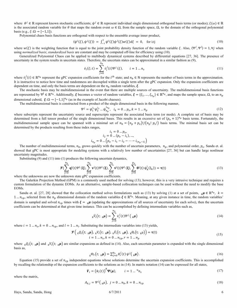
A single 2D plane from the 3D Pareto optimal set showing the trade-off between the objective
constraint is held constant, ðñòóôõö÷ = ?. ?øù Ø. Both the deterministic (dOpt) and uncertain (uOpt) the presence of uncertainty requires an off-set of the Pareto optimal solution set to
The set enclosed by the ellipse correspond to Figure 6.
12
constraints may be defined as,
(45)
represent scaling factors of the
conditions from a standard deviation perspective. The uncertain holding constraint
(46)
result in a reduced set of efficient operations on the
eviation sense. This means a subset of the systems
still not satisfy the constraints. In order to guarantee that all systems within the probability space will satisfy the
statistics are used instead of the standard
, may be used to ‘tune’ the design such that
a desired percentage of the systems from the probability space will satisfy the constraints. This point is illustrated in greater detail in the following
.A, that minimize the ride being
Table 1 details all the uncertain
best illustrate the benefits of treating uncertainty during the optimal design process. These results clearly show that the
is the 2D Pareto curve showing trade-
cular to that shown in Figure 4; this figure shows
show the Pareto curves flattening out at some point. This occurs when the system transitions from one active
traint while the curve has a negative slope. However, when the
is constant in this plane the Pareto curve has a slope of zero. The same
constraint is active and then the system transitions to the flat rattle
off between the objective ride and rattle
Both the deterministic (dOpt) and uncertain (uOpt)
set of the Pareto optimal solution set to
Hays, Sandu, Sandu, Hong
Figure 5—A single 2D plane from the 3D Pareto optimal set showing the trade
constraint; both the compression and extension
deterministic (dOpt) and uncertain (uOpt) cases are shown. These results
off-set of the Pareto optimal solution set to realize a more robust
One distinct difference is apparent between Figure
before the uncertain curve. However, Figure 5 has an opposite behavior; the uncertain curve transitions before the deterministic one.
Figure 7 help illustrate why this inconsistent behavior exists.
planes, úШ"#$û/¨Ï, úШ"#$û/#"Ï, ¨Ï/#"Ï0.034 ¿ the deterministic optimal design has an active
the uncertain ¬ppÇË∗ is so large, the optimal design was pushed to a significantly lower
value; thus, the deterministic Pareto transitions first. This same behavior is apparent in ¨Ï plane. Figure 5 presents the Pareto relating the
the uncertainty box enclosing the uncertain mean design
encounters the rattle constraint before the corresponding deterministic solution does.
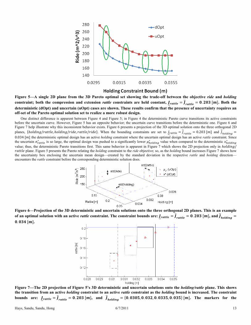
Figure 6—Projection of the 3D deterministic and uncertain solutions onto th
of an optimal solution with an active rattle constraint.?. ?øù Ø.
Figure 7—The 2D projection of Figure 5’s 3D
the transition from an active holding constraint
bounds are: ðýþó = ðýþó = ?.?ø Ø, and 6/7/2011
rom the 3D Pareto optimal set showing the trade-off between the objective
constraint; both the compression and extension rattle constraints are held constant, ðýþó = ðýþódeterministic (dOpt) and uncertain (uOpt) cases are shown. These results confirm that the presence of uncertainty requires an
set of the Pareto optimal solution set to realize a more robust design.
Figure 4 and Figure 5; in Figure 4 the deterministic Pareto curve transition
has an opposite behavior; the uncertain curve transitions before the deterministic one.
help illustrate why this inconsistent behavior exists. Figure 6 presents a projection of the 3D optimal solution onto the three orthogonal 2D #"Ï. When the bounding constraints are set to ʬppÇË = ʬppÇËthe deterministic optimal design has an active holding constraint where the uncertain optimal design has an active
is so large, the optimal design was pushed to a significantly lower 4Ç(2+∗ value when compared to the deterministic
value; thus, the deterministic Pareto transitions first. This same behavior is apparent in Figure 7 which shows the 2D projection only in
presents the Pareto relating the holding constraint to the ride objective; so, as the holding bound increases
the uncertainty box enclosing the uncertain mean design—created by the standard deviation in the respective
constraint before the corresponding deterministic solution does.
Projection of the 3D deterministic and uncertain solutions onto the three orthogonal 2D planes. This is an example
constraint. The constraint bounds are: ðýþó = ðýþó =
’s 3D deterministic and uncertain solutions onto the holding/rattle
constraint to an active rattle constraint as the holding bound is increased
, and ðñòóôõö÷ = ?. ?ø?, ?. ?ø, ?. ?øø, ?. ?ø Ø13
off between the objective ride and holding
ýþó = ?.?ø Ø. Both the that the presence of uncertainty requires an
the deterministic Pareto curve transitions its active constraints
has an opposite behavior; the uncertain curve transitions before the deterministic one. Figure 6 and
presents a projection of the 3D optimal solution onto the three orthogonal 2D
¬ppÇË = 0.203 ¿ and Ê4Ç(2+ =t where the uncertain optimal design has an active rattle constraint. Since
value when compared to the deterministic 4Ç(2+∗
which shows the 2D projection only in úШ"#$û/bound increases Figure 7 shows how
standard deviation in the respective rattle and holding direction—
e three orthogonal 2D planes. This is an example = ?.?ø Ø, and ðñòóôõö÷ =
holding/rattle plane. This shows
bound is increased. The constraint Ø. The markers for the

Hays, Sandu, Sandu, Hong 6/7/2011 14
deterministic and uncertain mean designs correspond within a given set. Also, the line of the uncertainty box associated with a
given set matches line of the holding bound for that set.
The corresponding 2D trade-off curve in the parameter space for the case corresponding to Figure 5 with ʬppÇË = ʬppÇË = 0.203 ¿ is shown
in Figure 8. This figure is instructive in that it shows the optimal mean spring constant, .A∗, is found to be at the lower bound, ., for a majority of
the designs. Only when Ê4Ç(2+ is equal to the two lowest values shown in Figure 5 does the optimal mean spring constant leave the lower bounding
constraint. This behavior makes sense in that the ride objective is most influenced by the . versus Á. [5]; therefore, as long as the active constraint
can be satisfied with .A = . then the Pareto curve is largely defined by the damping mean, Á.A. Again, the design from the new framework shifts the
optimal parameter set relative to that designed by a traditional deterministic optimal design.
Figure 8—Parameter Pareto trade-off curve when ðýþó = ðýþó = ?.?ø Ø. The final point that illustrates the benefits of the new framework is shown in Figure 9; this figure shows the resulting rattle constraint values of
the optimal deterministic design applied to an uncertain system. A 1000 sample Monte Carlo simulation shows that 59.6% of the systems violated the
constraints. However, the design produced by the new framework defined in (42)–(46), with unity standard deviation scaling, = 1, resulted in only
11.4% of the systems violating the constraints. Slightly increasing the standard deviation scaling to = 1.25 resulting in only 3.5% of the systems
failing to satisfy the constraints (see Figure 10). As described in Section 5.1.2, designers may choose to approach the problem with the constraints
defined with supremum and/or infimum measures to guarantee the entire family of systems in the probability space will satisfy the constraints.
However, this approach is relatively computationally costly. Therefore, a scaled standard deviation approach, as shown here, can yield an acceptably
robust design. Similar design results are observed with regards to an active holding constraint as well, but are not shown for brevity.
Figure 9—Monte Carlo results (1000 runs) showing 59.6% of the systems in the probability space violate the rattle constraints
when the deterministic optimal design is applied to an uncertain system; where ðýþó = ðýþó = ?. Ø and ðñòóôõö÷ =?. ?øù Ø.

Hays, Sandu, Sandu, Hong 6/7/2011 15
Figure 10—Constraint violations from designs produced with the new framework can be controlled, or tuned, with the proper
selection of the standard deviation scaling. Slightly increasing the scaling from þ = to þ = . reduces the number of systems violating the constraints from 11.4% to 3.5%; where 1000 Monte Carlo simulations were used to determined the
results; and ðýþó = ðýþó = ?. Ø and ðñòóôõö÷ = ?. ?øù Ø. 6 CONCLUSIONS
This work has presented a new framework for the parametric optimal design of uncertain ordinary differential equation systems. The framework
allows practitioners to model sources of uncertainty using the Generalized Polynomial Chaos methodology and to solve the dynamics using a least-
squares collocation method. Subsequently, statistical information from the uncertain dynamics can be included in formulations of the objective
function and of the constraints, to perform optimal designs under uncertainty. Robust designs benefit from the new framework when the system is
nonlinear, has active constraints, or is a multi-objective optimization problem. In the case of a multi-objective optimization problem, a constraint-
based formulation of the problem was shown to produce an off-set Pareto optimal trade-off curve confirming the need to directly treat uncertainties
during the optimal design phase. An optimal nonlinear vehicle suspension design problem, subject to parametric uncertainty, was used to illustrate
how the new framework produces an optimal design that accounts for the entire family of systems within the associated probability space. This adds
robustness to the design of the optimally performing system.
In future work the authors will expand the new framework to investigate optimal apportionment of uncertainty related to engineered components
within a system such as to minimize cost while preserving the performance specifications of the overall system.
ACKNOWLEDGEMENTS This work was partially supported by the Automotive Research Center (ARC), Thrust Area 1.
REFERENCES [1] Hays, J., Sandu, A., Sandu, C., and Hong, D., 2011, "Motion Planning of Uncertain Fully-Actuated Dynamical Systems—an Inverse Dynamics
Formulation," eds., Washington, DC, USA, pp. (accepted).
[2] Hays, J., Sandu, A., Sandu, C., and Hong, D., 2011, "Motion Planning of Uncertain Fully-Actuated Dynamical Systems—a Forward Dynamics
Formulation," eds., Washington, DC, USA, pp. (accepted).
[3] Hays, J., Sandu, A., Sandu, C., and Hong, D., 2011, "Motion Planning of Uncertain under-Actuated Dynamical Systems—a Hybrid Dynamics
Formulation," eds., Denver, CO, USA, pp. (submitted).
[4] Hays, J., Sandu, A., Sandu, C., and Hong, D., 2011, "Motion Planning of Uncertain Ordinary Differential Equation Systems," Technical Report
No. TR-11-04, Virginia Tech, Blacksburg, VA, USA.
[5] Gobbi, M., and Mastinu, G., 2001, "Analytical Description and Optimization of the Dynamic Behaviour of Passively Suspended Road Vehicles,"
Journal of Sound and Vibration, 245(3), pp. 457-481.
[6] Verros, G., Natsiavas, S., and Papadimitriou, C., 2005, "Design Optimization of Quarter-Car Models with Passive and Semi-Active Suspensions
under Random Road Excitation," Journal of Vibration and Control, 11(5), pp. 581-606.
[7] He, Y., and Mcphee, J., 2005, "Multidisciplinary Design Optimization of Mechatronic Vehicles with Active Suspensions," Journal of Sound and
Vibration, 283(1-2), pp. 217-241.
[8] He, Y., and Mcphee, J., 2007, "Application of Optimisation Algorithms and Multibody Dynamics to Ground Vehicle Suspension Design,"
International Journal of Heavy Vehicle Systems, 14(2), pp. 158-192.
[9] Alkhatib, R., Nakhaie Jazar, G., and Golnaraghi, M., 2004, "Optimal Design of Passive Linear Suspension Using Genetic Algorithm," Journal of
Sound and Vibration, 275(3-5), pp. 665-691.
[10] Jazar, R. N., 2008, Vehicle Dynamics: Theory and Application, Springer US, Suspension Optimization.
[11] Hrovat, D., 1993, "Applications of Optimal Control to Advanced Automotive Suspension Design," Journal of Dynamic Systems, Measurement,
and Control, 115(2B), pp. 328-342.

Hays, Sandu, Sandu, Hong 6/7/2011 16
[12] Georgiou, G., Verros, G., and Natsiavas, S., 2007, "Multi-Objective Optimization of Quarter-Car Models with a Passive or Semi-Active
Suspension System," Vehicle System Dynamics: International Journal of Vehicle Mechanics and Mobility, 45(1), pp. 77 - 92.
[13] Segla, S., and Reich, S., "Optimization and Comparison of Passive, Active, and Semi-Active Vehicle Suspension Systems," eds., pp.
[14] Baumal, A. E., Mcphee, J. J., and Calamai, P. H., 1998, "Application of Genetic Algorithms to the Design Optimization of an Active Vehicle
Suspension System," Computer methods in applied mechanics and engineering, 163(1-4), pp. 87-94.
[15] He, Y., and Mcphee, J., 2005, "Multidisciplinary Optimization of Multibody Systems with Application to the Design of Rail Vehicles,"
Multibody System Dynamics, 14(2), pp. 111-135.
[16] He, Y., and Mcphee, J., 2005, "A Design Methodology for Mechatronic Vehicles: Application of Multidisciplinary Optimization, Multibody
Dynamics and Genetic Algorithms," Vehicle System Dynamics: International Journal of Vehicle Mechanics and Mobility, 43(10), pp. 697 - 733.
[17] Good, and Mcphee, 1999, "Dynamics of Mountain Bicycles with Rear Suspensions: Modelling and Simulation," Sports Engineering
(International Sports Engineering Association), 2(3), pp.
[18] Good, C., and Mcphee, J., 2000, "Dynamics of Mountain Bicycles with Rear Suspensions: Design Optimization," Sports Engineering
(International Sports Engineering Association), 3(1), pp. 49-55.
[19] Papoulis, A., Pillai, S., and Unnikrishna, S., 2002, Probability, Random Variables, and Stochastic Processes, McGraw-Hill New York,
[20] Rensburg, E., and Torrie, G., 1993, "Estimation of Multidimensional Integrals: Is Monte Carlo the Best Method?," Journal of Physics A:
Mathematical and General, 26(pp. 943.
[21] Bratley, P., Fox, B., and Niederreiter, H., 1992, "Implementation and Tests of Low-Discrepancy Sequences," ACM Transactions on Modeling
and Computer Simulation (TOMACS), 2(3), pp. 213.
[22] Wiener, N., 1938, "The Homogeneous Chaos," American Journal of Mathematics, 60(4), pp. 897-936.
[23] Xiu, D., and Karniadakis, G., 2003, "The Wiener-Askey Polynomial Chaos for Stochastic Differential Equations," pp.
[24] Xiu, D., 2009, "Fast Numerical Methods for Stochastic Computations: A Review," Communications in Computational Physics, 5(2-4), pp. 242-
272.
[25] Xiu, D., and Hesthaven, J. S., 2005, "High-Order Collocation Methods for Differential Equations with Random Inputs," SIAM Journal on
Scientific Computing, 27(3), pp. 1118-1139.
[26] Xiu, D., 2007, "Efficient Collocational Approach for Parametric Uncertainty Analysis," Communications in Computational Physics, 2(2), pp.
293-309.
[27] Sandu, A., Sandu, C., and Ahmadian, M., 2006, "Modeling Multibody Systems with Uncertainties. Part I: Theoretical and Computational
Aspects," Multibody System Dynamics, 15(4), pp. 369-391.
[28] Cheng, H., and Sandu, A., 2009, "Efficient Uncertainty Quantification with the Polynomial Chaos Method for Stiff Systems," Mathematics and
Computers in Simulation, 79(11), pp. 3278-3295.
[29] Wan, X., and Karniadakis, G., 2005, "An Adaptive Multi-Element Generalized Polynomial Chaos Method for Stochastic Differential
Equations," Journal of Computational Physics, 209(2), pp. 617-642.
[30] Wan, X., and Karniadakis, G., "Adaptive Numerical Solutions of Stochastic Differential Equations," pp.
[31] Wan, X., and Karniadakis, G., 2006, "Beyond Wiener–Askey Expansions: Handling Arbitrary Pdfs," Journal of Scientific Computing, 27(1), pp.
455-464.
[32] Wan, X., and Karniadakis, G., 2007, "Multi-Element Generalized Polynomial Chaos for Arbitrary Probability Measures," SIAM Journal on
Scientific Computing, 28(3), pp. 901-928.
[33] Foo, J., Wan, X., and Karniadakis, G., 2008, "The Multi-Element Probabilistic Collocation Method: Error Analysis and Simulation," J. Comput.
Phys, 227(22), pp. 9572–9595.
[34] Foo, J., and Karniadakis, G. E., 2010, "Multi-Element Probabilistic Collocation Method in High Dimensions," Journal of Computational
Physics, 229(5), pp. 1536-1557.
[35] Gerritsma, M., Van Der Steen, J.-B., Vos, P., and Karniadakis, G., 2010, "Time-Dependent Generalized Polynomial Chaos," Journal of
Computational Physics, 229(22), pp. 8333-8363.
[36] Sandu, C., Sandu, A., and Ahmadian, M., 2006, "Modeling Multibody Systems with Uncertainties. Part Ii: Numerical Applications," Multibody
System Dynamics, 15(3), pp. 241-262.
[37] Cheng, H., and Sandu, A., 2007, "Numerical Study of Uncertainty Quantification Techniques for Implicit Stiff Systems," eds., Winston-Salem,
NC, USA, pp. 367-372.
[38] Cheng, H., and Sandu, A., 2009, "Uncertainty Quantification in 3d Air Quality Models Using Polynomial Chaoses," Environmental Modeling
and Software, 24(8), pp. 917-925.
[39] Cheng, H., and Sandu, A., 2009, "Uncertainty Apportionment for Air Quality Forecast Models," eds., Honolulu, HI, USA, pp. 956-960.
[40] Cheng, H., and Sandu, A., 2010, "Collocation Least-Squares Polynomial Chaos Method," eds., Orlando, FL, USA, pp. 80.
[41] Blanchard, E., 2010, "Polynomial Chaos Approaches to Parameter Estimation and Control Design for Mechanical Systems with Uncertain
Parameters," Ph.D. thesis,
[42] Blanchard, E., Sandu, A., and Sandu, C., 2007, "Parameter Estimation Method Using an Extended Kalman Filter," eds., Fairbanks, Alaska,
USA, pp. 23-26.
[43] Blanchard, E., Sandu, A., and Sandu, C., 2009, "Parameter Estimation for Mechanical Systems Via an Explicit Representation of Uncertainty,"
Engineering Computations, 26(5), pp. 541-569.
[44] Blanchard, E., Sandu, A., and Sandu, C., 2010, "Polynomial Chaos-Based Parameter Estimation Methods Applied to a Vehicle System,"
Proceedings of the Institution of Mechanical Engineers, Part K: Journal of Multi-body Dynamics, 224(1), pp. 59-81.
[45] Blanchard, E., Sandu, A., and Sandu, C., 2010, "Polynomial Chaos Based Method for the Lqr Problem with Uncertain Parameters in the
Formulation," eds., Montreal, CA, pp.
[46] Blanchard, E., Sandu, C., and Sandu, A., 2007, "A Polynomial-Chaos-Based Bayesian Approach for Estimating Uncertain Parameters of
Mechanical Systems," eds., Las Vegas, NV, USA, pp. 4-7.
[47] Blanchard, E., Sandu, C., and Sandu, A., 2009, "Comparison between a Polynomial-Chaos-Based Bayesian Approach and a Polynomial-Chaos-
Based Ekf Approach for Parameter Estimation with Application to Vehicle Dynamics," eds., San Diego, CA, USA, pp.

Hays, Sandu, Sandu, Hong 6/7/2011 17
[48] Blanchard, E., and Sandu, D., 2007, "A Polynomial Chaos Based Bayesian Approach for Estimating Uncertain Parameters of Mechanical
Systems-Part Ii: Applications to Vehicle Systems," pp.
[49] Blanchard, E., and Sandu, D., 2007, "A Polynomial Chaos Based Bayesian Approach for Estimating Uncertain Parameters of Mechanical
Systems–Part I: Theoretical Approach," pp.
[50] Blanchard, E. D., Sandu, A., and Sandu, C., 2010, "A Polynomial Chaos-Based Kalman Filter Approach for Parameter Estimation of
Mechanical Systems," Journal of Dynamic Systems, Measurement, and Control, 132(6), pp. 061404.
[51] Pence, B., Hays, J., Fathy, H., Sandu, C., and Stein, J., 2011, "Vehicle Sprung Mass Estimation for Rough Terrain," International Journal of
Vehicle Design, Special Issue on Modeling and Simulation of Ground Vehicle Systems(pp. (submitted).
[52] Pence, B. L., Fathy, H. K., and Stein, J. L., 2009, "A Base-Excitation Approach to Polynomial Chaos-Based Estimation of Sprung Mass for Off-
Road Vehicles," eds., n PART A, pp. 857-864.
[53] Pence, B. L., Fathy, H. K., and Stein, J. L., 2010,
[54] Pence, B. L., Fathy, H. K., and Stein, J. L., 2010,
[55] Southward, S., 2007, "Real-Time Parameter Id Using Polynomial Chaos Expansions," eds., Seattle, WA, USA, pp.
[56] Shimp Iii, S., 2008, "Vehicle Sprung Mass Parameter Estimation Using an Adaptive Polynomial-Chaos Method," pp.
[57] Marzouk, Y., and Xiu, D., 2009, "A Stochastic Collocation Approach to Bayesian Inference in Inverse Problems," Communications in
Computational Physics, 6(pp. 826–847.
[58] Marzouk, Y. M., Najm, H. N., and Rahn, L. A., 2007, "Stochastic Spectral Methods for Efficient Bayesian Solution of Inverse Problems,"
Journal of Computational Physics, 224(2), pp. 560-586.
[59] Price, D., 2008, "Estimation of Uncertain Vehicle Center of Gravity Using Polynomial Chaos Expansions," Ph.D. thesis, Virginia Polytechnic
Institute and State University,
[60] Smith, A., Monti, A., and Ponci, F., 2007, "Indirect Measurements Via a Polynomial Chaos Observer," IEEE Transactions on Instrumentation
and Measurement, 56(3), pp. 743-752.
[61] Li, J., and Xiu, D., 2009, "A Generalized Polynomial Chaos Based Ensemble Kalman Filter with High Accuracy," Journal of Computational
Physics, 228(15), pp. 5454-5469.
[62] Saad, G., Ghanem, R., and Masri, S., 2007, "Robust System Identification of Strongly Non-Linear Dynamics Using a Polynomial Chaos Based
Sequential Data Assimilation Technique," eds., 6, pp. 6005-13.
[63] Templeton, B., 2009, "A Polynomial Chaos Approach to Control Design," Ph.D. thesis,
[64] Smith, A., Monti, A., and Ponci, F., 2006, "Robust Controller Using Polynomial Chaos Theory," eds., 5, pp.
[65] Prempraneerach, P., Hover, F., Triantafyllou, M., and Karniadakis, G., 2010, "Uncertainty Quantification in Simulations of Power Systems:
Multi-Element Polynomial Chaos Methods," Reliability Engineering & System Safety, pp.
[66] Kewlani, G., and Iagnemma, K., 2009, "A Multi-Element Generalized Polynomial Chaos Approach to Analysis of Mobile Robot Dynamics
under Uncertainty," eds., pp. 1177-1182.
[67] Greenwood, D., 2003, Advanced Dynamics, Cambridge Univ Pr,
[68] Murray, R., Li, Z., Sastry, S., and Sastry, S., 1994, A Mathematical Introduction to Robotic Manipulation, CRC Press, Inc, Boca Raton, FL,
USA.
[69] Nikravesh, P. E., 2004, Product Engineering, Springer, An Overview of Several Formulations for Multibody Dynamics.
[70] Haug, E. J., 1989, Computer Aided Kinematics and Dynamics of Mechanical Systems. Vol. 1: Basic Methods, Allyn & Bacon, Inc.,
[71] Diehl, M., Ferreau, H., and Haverbeke, N., 2009, "Efficient Numerical Methods for Nonlinear Mpc and Moving Horizon Estimation," Nonlinear
Model Predictive Control, pp. 391-417.
[72] Biegler, L. T., 2003, "Optimization of Ode/Dae Constrained Models," Technical Report No.
[73] Biegler, L. T., and Grossmann, I. E., 2004, "Retrospective on Optimization," Computers & Chemical Engineering, 28(8), pp. 1169-1192.