computer numerical control for windows version … · 2 flashcut cnc section 1 getting started new...
TRANSCRIPT
® CONTROL MADE SIMPLE
Computer Numerical Control for Windows Version 2.1
User’s Guide
© 1997-2004 WPI, Inc. All rights reserved. (Rev 8)
West Coast Office 1263 El Camino Real
Menlo Park, CA 94025 Phone (650) 853-1444 ♦ Fax (650) 853-1405
www.flashcutcnc.com
Midwest Office 444 Lake Cook Road, Suite 17
Deerfield, IL 60015 Phone (847) 940-9305 ♦ Fax (847) 940-9315
www.flashcutcnc.com

Table of Contents 1. GETTING STARTED.........................................................................................................................................1
THANK YOU ...............................................................................................................................................................1 PRODUCT SUPPORT ....................................................................................................................................................1 NEW FEATURES..........................................................................................................................................................2 SYSTEM REQUIREMENTS ............................................................................................................................................3 INSTALLING FLASHCUT CNC.....................................................................................................................................4 SAFETY AND USAGE GUIDELINES...............................................................................................................................5 ABOUT THIS MANUAL ................................................................................................................................................6
2. MAIN SCREEN FEATURES.............................................................................................................................7 PULL-DOWN MENU BAR ............................................................................................................................................8
File Menu ..............................................................................................................................................................8 Configuration menu.............................................................................................................................................10 Controller Menu ..................................................................................................................................................10 View Menu...........................................................................................................................................................13 Coordinates Menu ...............................................................................................................................................14 Help Menu ...........................................................................................................................................................15
DRO BOX ................................................................................................................................................................15 Coordinate Systems .............................................................................................................................................15 Command Buttons ...............................................................................................................................................16 Popup Menus.......................................................................................................................................................17
TOOLPATH VIEWPORT BOX......................................................................................................................................20 CONTROL SELECTION BOX.......................................................................................................................................22
G-Code Control Panel.........................................................................................................................................22 Jog Control Panel................................................................................................................................................24 Point Control Panel.............................................................................................................................................25 Home Control Panel............................................................................................................................................28 Auxiliary Control Panel.......................................................................................................................................29
TOOL BOX................................................................................................................................................................30 ONLINE STATUS BOX ...............................................................................................................................................30 PROGRAM LISTING BOX ...........................................................................................................................................31
3. INITIAL SETUP ...............................................................................................................................................33 WINDOWS SETUP .....................................................................................................................................................33 SOFTWARE SETUP ....................................................................................................................................................33
The Configuration Files.......................................................................................................................................33 System Settings ....................................................................................................................................................34 Communications Settings ....................................................................................................................................36 Motor Signal Settings ..........................................................................................................................................37 Machine Tool Settings .........................................................................................................................................40 Homing Settings...................................................................................................................................................42 Feedrate and Ramping Settings...........................................................................................................................43 Setting Up Backlash Compensation.....................................................................................................................49 Reference Point Settings......................................................................................................................................49 Point List Settings................................................................................................................................................50 Fixture Offset Settings .........................................................................................................................................51 Input Line Settings...............................................................................................................................................52 Output Line Settings ............................................................................................................................................54 Analog Output Line Settings................................................................................................................................56 Tool Change Settings...........................................................................................................................................56 M-Code Definitions .............................................................................................................................................60 M-Code Execution Settings .................................................................................................................................61 G-Code Settings...................................................................................................................................................63 Cutter Compensation Settings .............................................................................................................................65 Threading Settings...............................................................................................................................................66

Tool Length Sensing Settings ...............................................................................................................................66 Viewport Settings .................................................................................................................................................68 Security Settings...................................................................................................................................................69 Tooling Settings ...................................................................................................................................................70 Tools in Changer Settings....................................................................................................................................72 File Settings .........................................................................................................................................................72 Message Settings..................................................................................................................................................73 Setting Machine Zero...........................................................................................................................................75
4. SYSTEM PROGRAMMING............................................................................................................................77 OPENING A G-CODE PROGRAM ................................................................................................................................77 IMPORTING A DXF FILE ...........................................................................................................................................77 USING THE PROGRAM EDITOR ..................................................................................................................................80
File Menu.............................................................................................................................................................81 Edit Menu.............................................................................................................................................................81 Help Menu ...........................................................................................................................................................82 Buttons .................................................................................................................................................................82
G CODES SUPPORTED ...............................................................................................................................................83 M CODES SUPPORTED ..............................................................................................................................................84 OTHER COMMANDS SUPPORTED...............................................................................................................................85 ADVANCED KEYWORD COMMANDS AND FUNCTIONS ..............................................................................................85 KEY PROGRAMMING CONCEPTS ...............................................................................................................................85
Mode ....................................................................................................................................................................85 Absolute vs. Incremental......................................................................................................................................87
G AND M CODE REFERENCE.....................................................................................................................................87 G00 Rapid Tool Positioning ................................................................................................................................87 G01 Linear Interpolated Feedrate Move .............................................................................................................88 G02 Clockwise Circular Feedrate Move .............................................................................................................90 G03 Counter Clockwise Circular Feedrate Move ...............................................................................................93 G04 Dwell............................................................................................................................................................94 G17, G18, G19 Arc Plane Selection ....................................................................................................................94 G20, G21 Inch Units and Metric Units................................................................................................................95 G27 Home to Switches.........................................................................................................................................95 G28, G30 Move to Reference Point .....................................................................................................................95 G29 Return from Reference Point........................................................................................................................96 G40, G41, G42 Cutter Compensation..................................................................................................................97 G52 Local Coordinate System .............................................................................................................................99 G53, G53.1 Linear Move to Machine Coordinates............................................................................................100 G54-59, G54.1, G92 Set Program Zero Commands..........................................................................................100 M06 Tool Change and T Select Tool Commands...............................................................................................102 G43, G44, G49 Tool Length/Geometry Compensation Commands...................................................................102 G73, G80, G81, G82, G83, G85, G98, G99 Drilling Canned Cycle Commands...............................................106 G76 Thread Cutting Canned Cycle Command ..................................................................................................110 G90 Absolute Positioning Mode ........................................................................................................................113 G91 Incremental Positioning Mode...................................................................................................................113 M00 Program Pause..........................................................................................................................................114 M01 Optional Program Pause...........................................................................................................................114 M30, M30.1 End of Program.............................................................................................................................114 M98, M99, M02 Subroutine Commands ............................................................................................................114 M100, M101 Wait for Input Line .......................................................................................................................116 M03, M05, M07, M08, M09, M50, M51, MXX Auxiliary Device Control .........................................................117 F Set Feedrate Command ..................................................................................................................................118 S Set Spindle Speed Command...........................................................................................................................118 Program Comments ...........................................................................................................................................119 Optional Line .....................................................................................................................................................119
ADVANCED PROGRAMMING REFERENCE................................................................................................................119 Values ................................................................................................................................................................119 Variables............................................................................................................................................................120 Operators...........................................................................................................................................................128
Flow Of Control ................................................................................................................................................ 131 Additional Keywords ......................................................................................................................................... 136 Built In Functions .............................................................................................................................................. 138
5. TUTORIAL...................................................................................................................................................... 139 STARTING FLASHCUT CNC.................................................................................................................................... 139 CONFIGURING FLASHCUT CNC ............................................................................................................................. 140 LOADING A G-CODE FILE....................................................................................................................................... 141 VIEWING THE TOOL PATH ...................................................................................................................................... 142 ANIMATING THE G-CODE FILE............................................................................................................................... 144 EDITING A G-CODE FILE ........................................................................................................................................ 144 GOING ONLINE....................................................................................................................................................... 145 USING THE JOG CONTROLS..................................................................................................................................... 146 SETTING MACHINE ZERO ....................................................................................................................................... 147 USING THE POINT MOVE ........................................................................................................................................ 148 SETTING PROGRAM ZERO ON THE MACHINE TOOL ................................................................................................ 149 TESTING THE PROGRAM ON THE MACHINE TOOL................................................................................................... 150 CUTTING THE PART ................................................................................................................................................ 150 EXITING THE PROGRAM.......................................................................................................................................... 151 TURNING OFF THE ELECTRONICS............................................................................................................................ 151
6. GLOSSARY ..................................................................................................................................................... 153


FlashCut CNC Section 1 Getting Started 1
Section 1. Getting Started
Thank You Thank you for purchasing FlashCut™ CNC, the intuitive, powerful CNC control system for Windows NT, 2000 and XP. No control system is easier to set up and use. With intuitive controls and real time graphics, FlashCut CNC lets you make parts quickly and accurately on your machine tool.
We are extremely committed to the excellence and ongoing enhancement of FlashCut CNC. Feel free to call us with any comments or questions.
Product Support We are very committed to full support of FlashCut CNC products. We have many resources dedicated to helping you resolve your problems quickly. Please use these resources in the following order:
1. Web Site: www.flashcutcnc.com
Our website has product specifications, documentation and a dedicated support section containing Trouble Shooting Guides and FAQ’s.
2. Dealer Support:
If you purchased FlashCut CNC from a dealer or other machine tool manufacturer, please contact them as they will have the best knowledge of your complete system.
3. E-mail: [email protected]
E-mail is the most organized way to convey your issues to our support staff. In your e-mail, please state your problem completely. Include your FlashCut version, the processor and speed of your computer, your version of windows and your signal generator serial number. Attach your Setup and Tooling files (usually found in a folder named c:\flashcut data) and, when appropriate, the G-Code file with which you are having problems.
4. Phone/Fax Support
If e-mail is unavailable to you, please call one of our telephone support numbers. We will normally respond to your call within 24 hours.
West Coast
Phone: (650) 853-1444 (9:00 AM-5:00 PM, PST, M-F) Fax: (650) 853-1405
Midwest
Phone: (847) 940-9305 (9:00 AM-5:00 PM, CST, M-F) Fax: (847) 940-9315

FlashCut CNC Section 1 Getting Started 2
New Features We are always adding new features and capabilities to FlashCut CNC. Some of the important new features in FlashCut 2.0 are:
• Cutter Compensation (G41/G42)
• Fixture Offset Commands (G54-G59, plus G54.1 for 100 additional offsets)
• Set Program Zero Command (G92)
• Helical Interpolation (G02/G03 enhancement)
• New Drill Cycles (G82 Counterboring, G85 Reaming)
• Move to Reference Point Command (G30)
• Homing Command (G27)
• Thread Cutting for Lathes (G76)
• Spindle Speed Command (S)
• Move to Machine Coordinates Command (G53)
• Optional Program Pause Command (M01)
• Reset and Restart File (M30.1)
• Optional Line Command (/)
• Advanced Programming Features (Variables, Loops, Branching, Arithmetic, and more)
• Dynamic Feedrate Override (adjust feedrate override from 2 – 9999% while machine is moving)
• Expanded I/O Support (8 additional digital I/O lines, analog output for controlling spindle speed, encoder input for thread cutting)
• M00 Command with Message to Operator
• Jump to Any Line in Program
• 3D Isometric View of Toolpath
• 3D Isometric + Rotary Axis View of Toolpath
• XY, XZ and YZ Views of Toolpath
• Improved Z-Axis Viewport
• Jog Incremental Distances
• Improved Continuous Contouring
• Much Faster Loading and Preview of Large Files
FlashCut CNC Section 1 Getting Started 3
• New Option for Instant Loading of Large Files (No File Checking or Toolpath Preview Required)
• Improved Editor with Many New Features
• Tool Geometry Stored in Separate Configuration File
• M-Code Macros
• Three Modes for Automatic Execution of M-Codes
• More Input Line Options including Feed Hold
• Expanded Homing Options
• Recently Used G-Code Files List
• Offline Simulation with Accurate Feedrates
• New DXF Import Options
• Application of Linear Feedrates to Rotary Moves
• All-in-One Configuration Screen
• Progress Meter including Total Time to Run File and Time Remaining
• Line Numbers in Program Listing Box
• Advanced 32-Bit, Object-Oriented Architecture
• Support for Automatic Tool Changers
• Automatic Tool Length Sensing
• Customizable Point List on Point Control Panel
• Safety Interlocks for Output Lines
System Requirements • IBM PC or 100% compatible with a 700 MHz or faster processor.
• Microsoft Windows NT, 2000 or XP. Windows 95 and 98 are not supported.
• At least 128 MB of RAM (at least 256 MB preferred for large G-code files).
• Hard drive with at least 20MB of space available.
• CD drive.
• A Microsoft-compatible mouse. Note that for best performance, the mouse should connect directly to the bus (the standard mouse plug on most systems), or through a mouse bus port rather than through a serial port.

FlashCut CNC Section 1 Getting Started 4
• One available RS-232 serial port. If the port has a 25-pin connector, a 9-pin male to 25-pin female adapter will be required. If you have a laptop without a serial port, PCMCIA serial cards are available.
Installing FlashCut CNC It’s easy to install FlashCut CNC.
1. Close all applications
2. Insert the FlashCut CD into the CD drive. On most PC’s, the installation program will start automatically after a few seconds, and you can continue with step 3 below.
3. If your PC is configured not to start CD installations automatically, double-click the program icon labeled ‘Setup.exe’.
4. Follow the on-screen instructions.
If you are currently using FlashCut version 1.61 or earlier, note that FlashCut CNC 2 will be installed completely separate from your FlashCut 1.XX installation and will not affect it in any way.

FlashCut CNC Section 1 Getting Started 5
Safety and Usage Guidelines
When running an automated machine tool, safety is of utmost importance. For proper and safe use of the FlashCut CNC program and your CNC machine, the following safety guidelines must be followed:
1. Never let the machine tool run unattended.
2. Require any person in the same room as a running machine tool to wear safety goggles, and to stay a safe distance from the machine.
3. Allow only trained operators to run the machine tool. Any operator must have:
• Knowledge of machine tool operation
• Knowledge of personal computer operation
• Knowledge of Microsoft Windows
• Good common sense
4. Place safety guards around the machine to prevent injury from flying objects. It is highly recommended that you build a safety shield around the entire tool envelope.
5. Never place any part of your body within the tool envelope while the machine is online, since unexpected machine movement can occur at any time.
6. Always keep the tool envelope tidy and free of any loose objects.
7. Be on alert for computer crashes at all times.
WPI, Inc. is not responsible for the safe installation and use of this product. You and only you are responsible for the safety of yourself and others during the operation of your CNC machine tool. WPI supplies this product but has no control over how it is installed or used. Always be careful!
WPI, Inc. is not responsible for damage to any equipment or workpiece resulting from use of this product.
If you do not understand and agree with all of the above, please do not use this product.
FlashCut CNC Section 1 Getting Started 6
About this Manual FlashCut CNC is a unique Windows application, so you’ll need some instruction to get started. Since automated machining is potentially dangerous, please take the time to completely read through this manual to understand operation of the software before running the system.
Please note that all CNC terminology, and terminology particular to FlashCut CNC, appears in boldface upon first occurrence and is defined in the glossary.
It is assumed that you already have a working knowledge of the PC and Windows. If you are not familiar with either of these, please review your PC or Windows user’s guides before you use FlashCut CNC.
FlashCut CNC Section 2 Main Screen Features 7
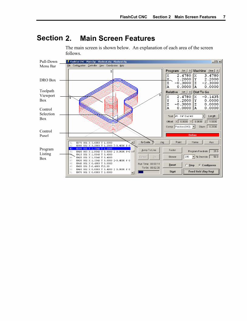
Section 2. Main Screen Features The main screen is shown below. An explanation of each area of the screen follows.
Pull-Down Menu Bar
DRO Box
Toolpath Viewport Box
Control Selection Box
Control Panel
Program Listing Box
FlashCut CNC Section 2 Main Screen Features 8
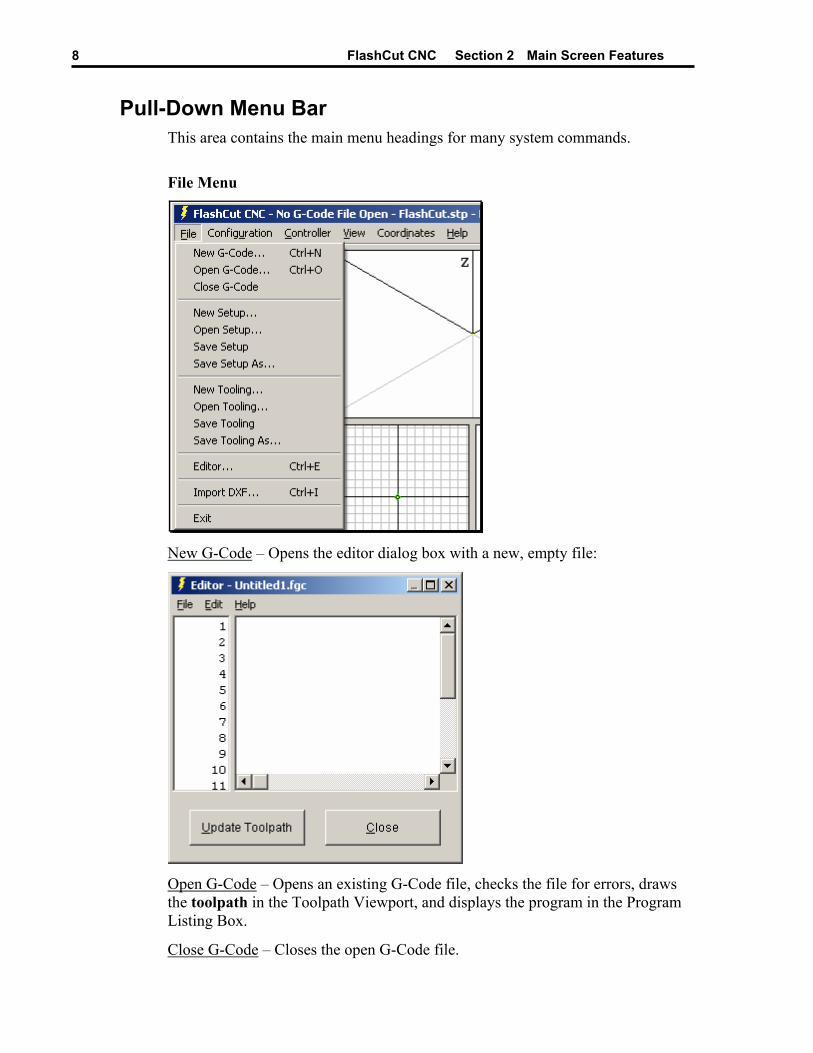
Pull-Down Menu Bar This area contains the main menu headings for many system commands.
File Menu
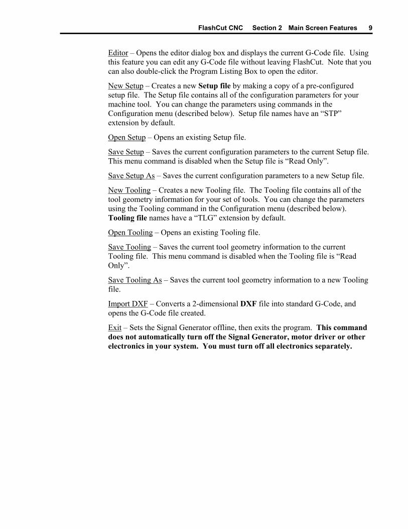
New G-Code – Opens the editor dialog box with a new, empty file:
Open G-Code – Opens an existing G-Code file, checks the file for errors, draws the toolpath in the Toolpath Viewport, and displays the program in the Program Listing Box.
Close G-Code – Closes the open G-Code file.
FlashCut CNC Section 2 Main Screen Features 9
Editor – Opens the editor dialog box and displays the current G-Code file. Using this feature you can edit any G-Code file without leaving FlashCut. Note that you can also double-click the Program Listing Box to open the editor.
New Setup – Creates a new Setup file by making a copy of a pre-configured setup file. The Setup file contains all of the configuration parameters for your machine tool. You can change the parameters using commands in the Configuration menu (described below). Setup file names have an “STP” extension by default.
Open Setup – Opens an existing Setup file.
Save Setup – Saves the current configuration parameters to the current Setup file. This menu command is disabled when the Setup file is “Read Only”.
Save Setup As – Saves the current configuration parameters to a new Setup file.
New Tooling – Creates a new Tooling file. The Tooling file contains all of the tool geometry information for your set of tools. You can change the parameters using the Tooling command in the Configuration menu (described below). Tooling file names have a “TLG” extension by default.
Open Tooling – Opens an existing Tooling file.
Save Tooling – Saves the current tool geometry information to the current Tooling file. This menu command is disabled when the Tooling file is “Read Only”.
Save Tooling As – Saves the current tool geometry information to a new Tooling file.
Import DXF – Converts a 2-dimensional DXF file into standard G-Code, and opens the G-Code file created.
Exit – Sets the Signal Generator offline, then exits the program. This command does not automatically turn off the Signal Generator, motor driver or other electronics in your system. You must turn off all electronics separately.
FlashCut CNC Section 2 Main Screen Features 10
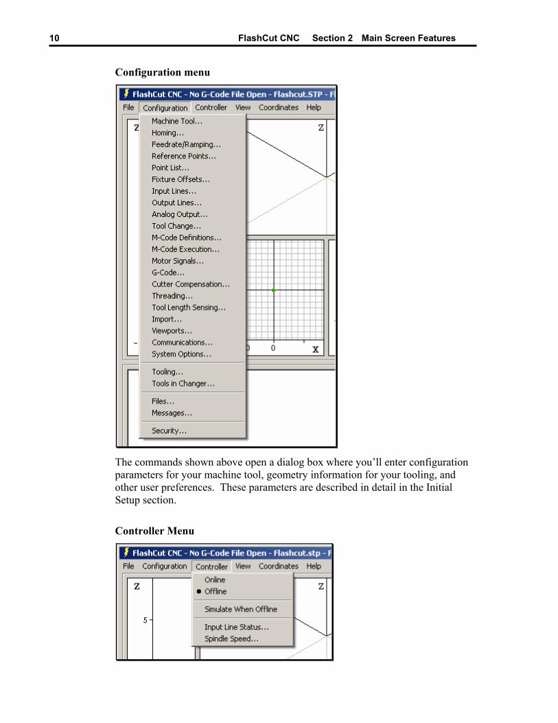
Configuration menu
The commands shown above open a dialog box where you’ll enter configuration parameters for your machine tool, geometry information for your tooling, and other user preferences. These parameters are described in detail in the Initial Setup section.
Controller Menu

FlashCut CNC Section 2 Main Screen Features 11
Online – Establishes communications with the Signal Generator. Once communications are established, FlashCut places a check mark next to this menu item. When the Signal Generator is online, all move commands will be executed by the machine tool, and the screen will update in real time.
Once the unit goes online, a safety reminder screen appears. It is imperative that you and anyone else near the machine understand, agree and adhere to all of the safety guidelines. If the safety guidelines are not accepted, the Signal Generator will immediately go offline.
Offline – Terminates communication with the Signal Generator. When the Signal Generator is offline, FlashCut places a check mark next to this menu item. In this mode, the screen will update, but the machine tool will not move. This option lets you “animate” a G-Code file, which is useful for debugging before cutting a part.
Simulate when Offline – When checked, FlashCut displays machine motion at accurate speeds when the Signal Generator is offline. When unchecked, FlashCut displays machine motion as quickly as your PC will allow.
FlashCut CNC Section 2 Main Screen Features 12
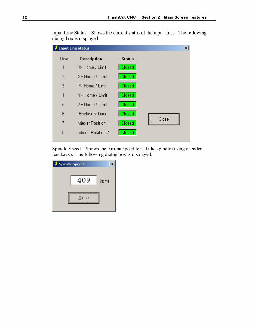
Input Line Status – Shows the current status of the input lines. The following dialog box is displayed:
Spindle Speed – Shows the current speed for a lathe spindle (using encoder feedback). The following dialog box is displayed:

FlashCut CNC Section 2 Main Screen Features 13
View Menu
All Fit Toolpath – Causes the toolpath for the current G-Code File to expand as much as possible within all Toolpath Viewports.
All Fit Machine – Causes the machine envelope to expand as much as possible within all Toolpath Viewports.
G-Code Panel, Jog Panel, Point Panel, Home Panel, Aux Panel – Selects the control panel to display. These commands are functionally identical to the buttons in the Control Selection Box, and their main purpose is to provide keyboard equivalents and shortcuts for those buttons. See “Control Selection Box” later in this section for a complete explanation of each command.
Program, Machine, Relative, Distance To Go, or All Coordinates – Selects the display mode for the DRO Box. Choosing Program Coordinates, Machine Coordinates, Relative Coordinates, or Distance To Go Coordinates will expand the chosen DRO into the entire DRO Box as shown below.
Choosing All Coordinates will display all four coordinate systems simultaneously in the DRO Box. You can also change these view modes by double-clicking any of the DRO’s.
FlashCut CNC Section 2 Main Screen Features 14
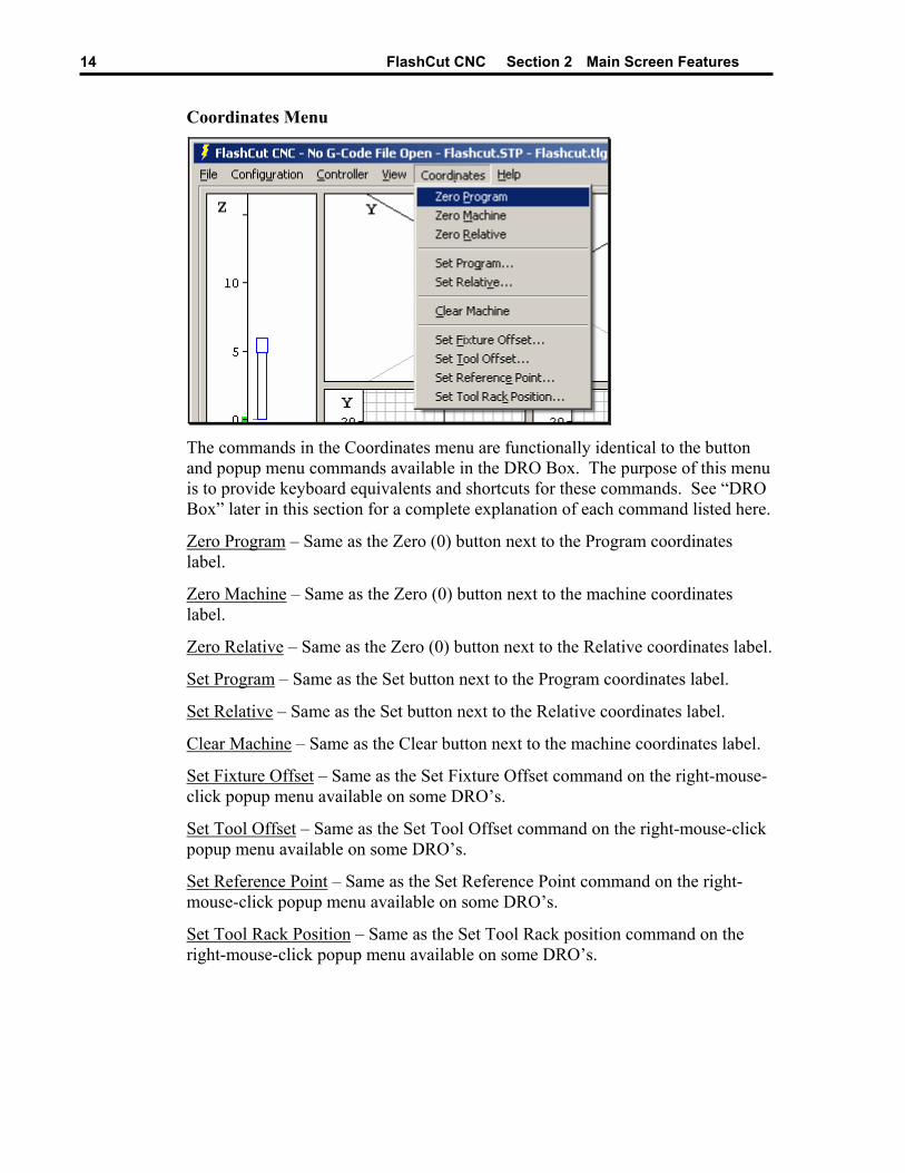
Coordinates Menu
The commands in the Coordinates menu are functionally identical to the button and popup menu commands available in the DRO Box. The purpose of this menu is to provide keyboard equivalents and shortcuts for these commands. See “DRO Box” later in this section for a complete explanation of each command listed here.
Zero Program – Same as the Zero (0) button next to the Program coordinates label.
Zero Machine – Same as the Zero (0) button next to the machine coordinates label.
Zero Relative – Same as the Zero (0) button next to the Relative coordinates label.
Set Program – Same as the Set button next to the Program coordinates label.
Set Relative – Same as the Set button next to the Relative coordinates label.
Clear Machine – Same as the Clear button next to the machine coordinates label.
Set Fixture Offset – Same as the Set Fixture Offset command on the right-mouse-click popup menu available on some DRO’s.
Set Tool Offset – Same as the Set Tool Offset command on the right-mouse-click popup menu available on some DRO’s.
Set Reference Point – Same as the Set Reference Point command on the right-mouse-click popup menu available on some DRO’s.
Set Tool Rack Position – Same as the Set Tool Rack position command on the right-mouse-click popup menu available on some DRO’s.

FlashCut CNC Section 2 Main Screen Features 15
Help Menu
User’s Guide – Displays the FlashCut CNC User’s Guide. You must have the Adobe Acrobat Reader installed (version 4 or higher) to view the User’s Guide. Once the User’s Guide is displayed, click the Bookmarks tab for easier navigation in Acrobat Reader.
About FlashCut CNC – Shows the FlashCut CNC software version number.
DRO Box The DRO Box shows the current tool position in Program, Machine, Relative and Distance to Go coordinates. It also has command buttons that set the coordinate values, and a right-mouse-click pull-down menu available for copying DRO values to the system configuration.
Clear Button
Zero Button
Set Button
Coordinate System Label
DRO
Coordinate Systems
Program
Displays the coordinates of the current position of the tool relative to Program Zero.
Machine
Displays the coordinates of the current position of the tool relative to Machine Zero. This coordinate system is undefined if Machine Zero has not been set (displays “N/A”).

FlashCut CNC Section 2 Main Screen Features 16
Relative
Displays the current relative coordinates. The relative coordinate system is general purpose and may be used for anything you choose. For instance, to measure the distance from any point, zero the relative coordinates at the point from which you want to measure.
Distance To Go
Displays the distance to the ending position of the current move.
Note that you can double-click any DRO to expand it to fill the entire DRO Box.
Command Buttons Zero Button – Sets X, Y, Z and A values of the indicated coordinate system to zero.
Set Button – Allows setting the X, Y, Z and A values of either program or relative coordinates to any value. When chosen, the following dialog box appears:
To set new values within a coordinate system
1. Type in the X, Y, Z and A values for each axis. These coordinates will become the current position of the tool.
2. Choose OK.
To zero specific axes individually
1. Choose the Zero button for each axis you want to zero.
2. Choose OK.
FlashCut CNC Section 2 Main Screen Features 17
To activate a fixture offset
1. Select an offset from the Use Fixture Offset pull-down menu. FlashCut automatically enters new coordinate values that activate the selected fixture offset. All fixture offsets are defined in the Fixture Offsets panel of the Configuration dialog box.
2. Choose OK.
Clear Button – Clears the current Machine Zero setting. This button is useful when you’ve set Machine Zero manually (using the Machine Coordinates Zero button) and need to make a correction to the Machine Zero location.
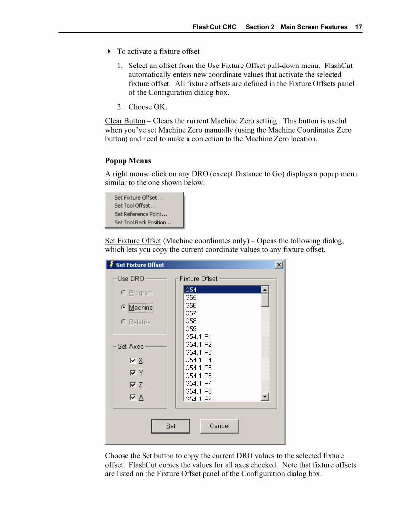
Popup Menus A right mouse click on any DRO (except Distance to Go) displays a popup menu similar to the one shown below.
Set Fixture Offset (Machine coordinates only) – Opens the following dialog, which lets you copy the current coordinate values to any fixture offset.
Choose the Set button to copy the current DRO values to the selected fixture offset. FlashCut copies the values for all axes checked. Note that fixture offsets are listed on the Fixture Offset panel of the Configuration dialog box.

FlashCut CNC Section 2 Main Screen Features 18
Set Tool Offset – Opens the following dialog, which lets you copy the current coordinate values to any tool offset.
Choose the Set button to copy the current DRO values to the selected tool offset. FlashCut copies the values for all axes checked. Note that tool offsets are listed on the Tooling panel of the Configuration dialog box.

FlashCut CNC Section 2 Main Screen Features 19
Set Reference Point (Machine and Program coordinates only) – Opens the following dialog, which lets you copy the current coordinate values to any reference point.
Choose the Set button to copy the current DRO values to the selected reference point. FlashCut copies the values for all axes checked. Note that reference points are listed on the Reference Points panel of the Configuration dialog box.

FlashCut CNC Section 2 Main Screen Features 20
Set Tool Rack Position (Machine coordinates only) – Opens the following dialog, which lets you copy the current coordinate values to any tool rack position.
Choose the Set button to copy the current DRO values to the selected tool rack position. FlashCut copies the values for all parameters checked. Note that tool rack positions are listed on the Tool Change panel of the Configuration dialog box.
Toolpath Viewport Box The Toolpath Viewport Box can display up to 10 different views of the toolpath described by the current G-Code file. You can select the views to display in the Viewports panel of the Configuration dialog (for more details, see “Viewports” in the Initial Setup section).
The figure below shows the Toolpath Viewport Box in a typical configuration for milling (XY and Z viewports displayed). The XY viewport shows an aerial view of the tool envelope. The Z viewport shows the height of the tool during machining. Green and light blue dots represent the origins of the Program and Machine (if used) coordinate systems respectively. The Machine Tool Envelope is shown as the light blue box on the XY viewport and by the light blue bar on the Z viewport.
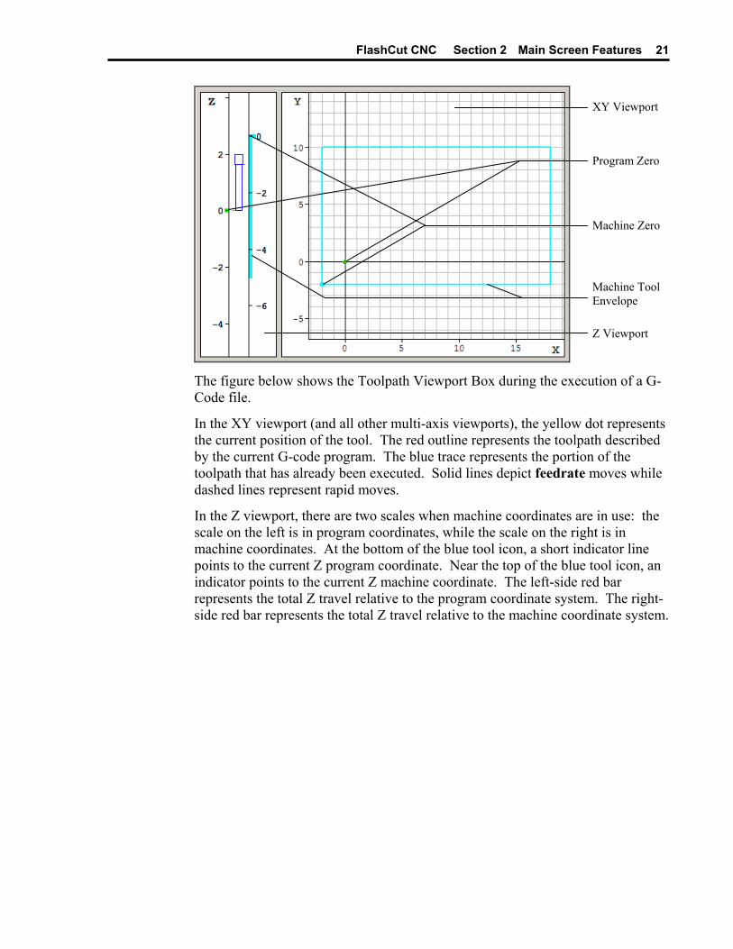
FlashCut CNC Section 2 Main Screen Features 21
XY Viewport
Program Zero
Machine Zero
Machine Tool Envelope
Z Viewport
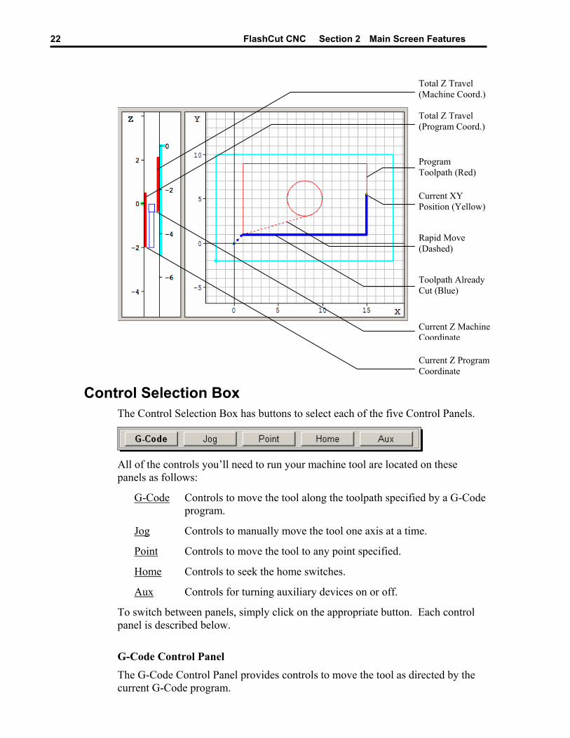
The figure below shows the Toolpath Viewport Box during the execution of a G-Code file.
In the XY viewport (and all other multi-axis viewports), the yellow dot represents the current position of the tool. The red outline represents the toolpath described by the current G-code program. The blue trace represents the portion of the toolpath that has already been executed. Solid lines depict feedrate moves while dashed lines represent rapid moves.
In the Z viewport, there are two scales when machine coordinates are in use: the scale on the left is in program coordinates, while the scale on the right is in machine coordinates. At the bottom of the blue tool icon, a short indicator line points to the current Z program coordinate. Near the top of the blue tool icon, an indicator points to the current Z machine coordinate. The left-side red bar represents the total Z travel relative to the program coordinate system. The right-side red bar represents the total Z travel relative to the machine coordinate system.
FlashCut CNC Section 2 Main Screen Features 22
Total Z Travel (Machine Coord.)
Total Z Travel (Program Coord.)
Program Toolpath (Red)
Current XY Position (Yellow)
Rapid Move (Dashed)
Toolpath Already Cut (Blue)
Current Z Machine Coordinate
Current Z Program Coordinate
Control Selection Box The Control Selection Box has buttons to select each of the five Control Panels.
All of the controls you’ll need to run your machine tool are located on these panels as follows:
G-Code Controls to move the tool along the toolpath specified by a G-Code program.
Jog Controls to manually move the tool one axis at a time.
Point Controls to move the tool to any point specified.
Home Controls to seek the home switches.
Aux Controls for turning auxiliary devices on or off.
To switch between panels, simply click on the appropriate button. Each control panel is described below.
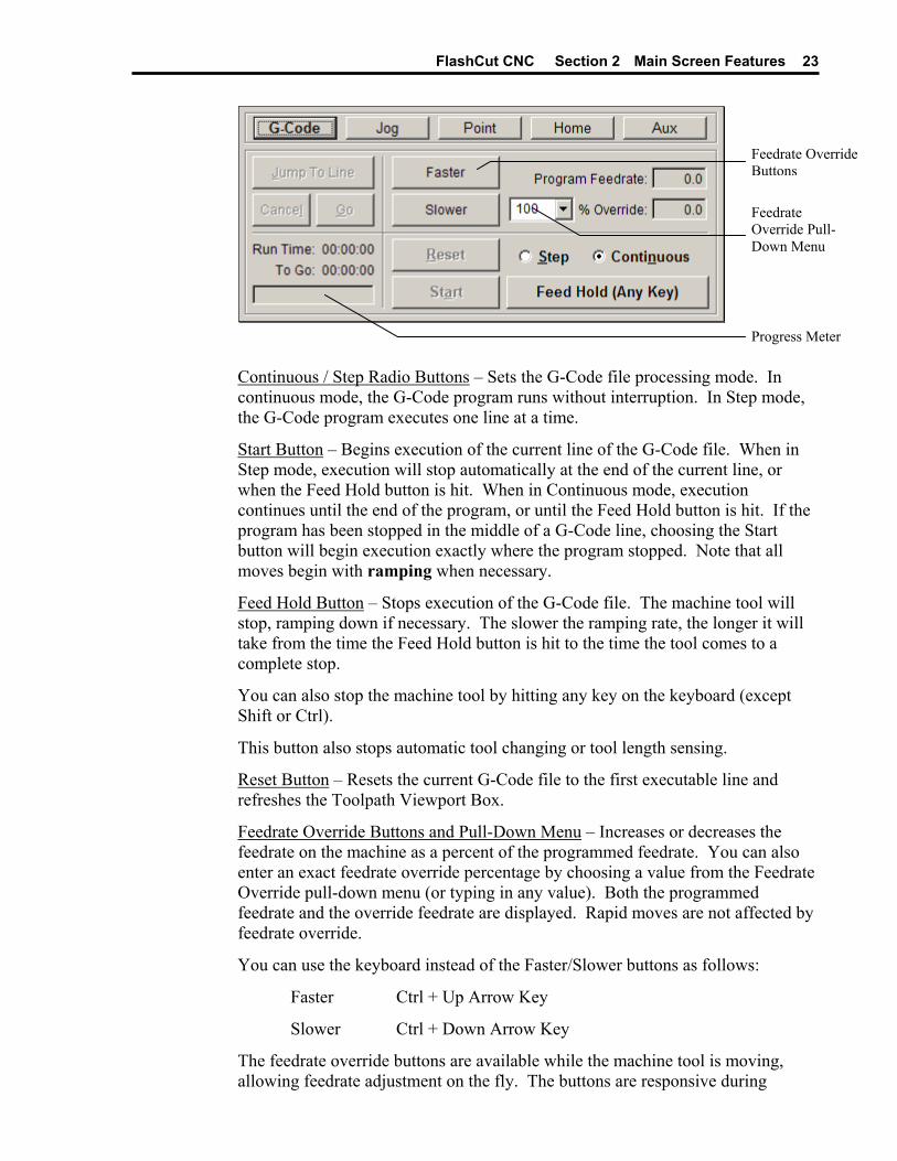
G-Code Control Panel The G-Code Control Panel provides controls to move the tool as directed by the current G-Code program.
FlashCut CNC Section 2 Main Screen Features 23
Feedrate Override Buttons
Feedrate Override Pull-Down Menu
Progress Meter
Continuous / Step Radio Buttons – Sets the G-Code file processing mode. In continuous mode, the G-Code program runs without interruption. In Step mode, the G-Code program executes one line at a time.
Start Button – Begins execution of the current line of the G-Code file. When in Step mode, execution will stop automatically at the end of the current line, or when the Feed Hold button is hit. When in Continuous mode, execution continues until the end of the program, or until the Feed Hold button is hit. If the program has been stopped in the middle of a G-Code line, choosing the Start button will begin execution exactly where the program stopped. Note that all moves begin with ramping when necessary.
Feed Hold Button – Stops execution of the G-Code file. The machine tool will stop, ramping down if necessary. The slower the ramping rate, the longer it will take from the time the Feed Hold button is hit to the time the tool comes to a complete stop.
You can also stop the machine tool by hitting any key on the keyboard (except Shift or Ctrl).
This button also stops automatic tool changing or tool length sensing.
Reset Button – Resets the current G-Code file to the first executable line and refreshes the Toolpath Viewport Box.
Feedrate Override Buttons and Pull-Down Menu – Increases or decreases the feedrate on the machine as a percent of the programmed feedrate. You can also enter an exact feedrate override percentage by choosing a value from the Feedrate Override pull-down menu (or typing in any value). Both the programmed feedrate and the override feedrate are displayed. Rapid moves are not affected by feedrate override.
You can use the keyboard instead of the Faster/Slower buttons as follows:
Faster Ctrl + Up Arrow Key
Slower Ctrl + Down Arrow Key
The feedrate override buttons are available while the machine tool is moving, allowing feedrate adjustment on the fly. The buttons are responsive during
FlashCut CNC Section 2 Main Screen Features 24
feedrate moves, but not during rapid moves or dwells. For dynamic feedrate adjustment during arc moves, the M202B chip is required in the Signal Generator.
Jump to Line Button – Lets you jump to any line in the G-Code file. When you click the button, FlashCut activates the Program Listing so you can select a G-Code line. The line you select must contain a command (it cannot be a comment or blank line). After you select an executable G-Code line, click the Go button to jump there, or the Cancel button to cancel the operation. If you click Go, FlashCut repositions the G-Code file, then displays a dialog giving you the option to move the machine tool to the correct location for restarting the file at the new G-Code line. (If you’re using automatic tool changing, FlashCut will first change to the correct tool.)
Run Time – Shows the total estimated time to run the G-Code file. This estimate takes the current feedrate override setting into account. It does not take into account ramping, direction change delays, or backlash compensation.
To Go – Shows the estimated time remaining to finish running the G-Code file.
Progress Meter – Shows the current progress running the file, based on the Run Time and To Go time.
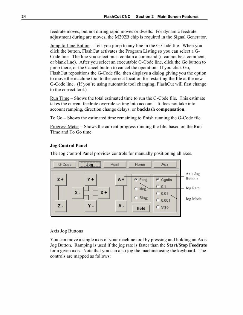
Jog Control Panel
The Jog Control Panel provides controls for manually positioning all axes.
Axis Jog Buttons
Jog Rate
Jog Mode
Axis Jog Buttons
You can move a single axis of your machine tool by pressing and holding an Axis Jog Button. Ramping is used if the jog rate is faster than the Start/Stop Feedrate for a given axis. Note that you can also jog the machine using the keyboard. The controls are mapped as follows:

FlashCut CNC Section 2 Main Screen Features 25
X+ Ctrl + Right Arrow Key X- Ctrl + Left Arrow Key Y+ Ctrl + Up Arrow Key Y- Ctrl + Down Arrow Key Z+ Ctrl + Page Up Key Z- Ctrl + Page Down Key A+ Ctrl + Plus (+) Key A- Ctrl + Minus (-) Key
Jog Rate
The Slow, Medium and Fast buttons set the jog rate to the corresponding rate specified in the Feedrate/Ramping panel of the Configuration dialog box. Note that there are separate jog rates defined for linear and rotary axis types.
Jog Mode
• Continuous – Sets FlashCut to move continuously while you hold down an Axis Jog button.
• Discrete Distances – Sets FlashCut to move the indicated distance each time you click an Axis Jog button.
• Step – Sets FlashCut to move exactly one motor step each time you click an Axis Jog button.
Hold Button
Stops motion during a discrete distance move. This button also stops automatic tool changing or tool length sensing.
Point Control Panel The Point Control Panel provides controls for moving the tool to any XYZA position at any feedrate.
FlashCut CNC does not always move all axes simultaneously. The sequence of axis motions follows a general-purpose scheme based on three fields in the Machine Tool and Homing Panels of the Configuration dialog box: Home End, Home Order, and Point Move Linear Interpolate. These fields should be configured to allow for safe moves in Point mode, which generally means the tool retracts from the workpiece before any other motion occurs. FlashCut uses the following rules to sequence the individual moves:
1. Do all non-interpolated moves that are towards the Home End, in the Home Order.
2. Do the interpolated move, if any.
3. Do all non-interpolated moves that are away from the Home End, in reverse Home Order.
By setting the three configuration fields properly, you can make the sequence safe for your machine tool configuration.
FlashCut CNC Section 2 Main Screen Features 26
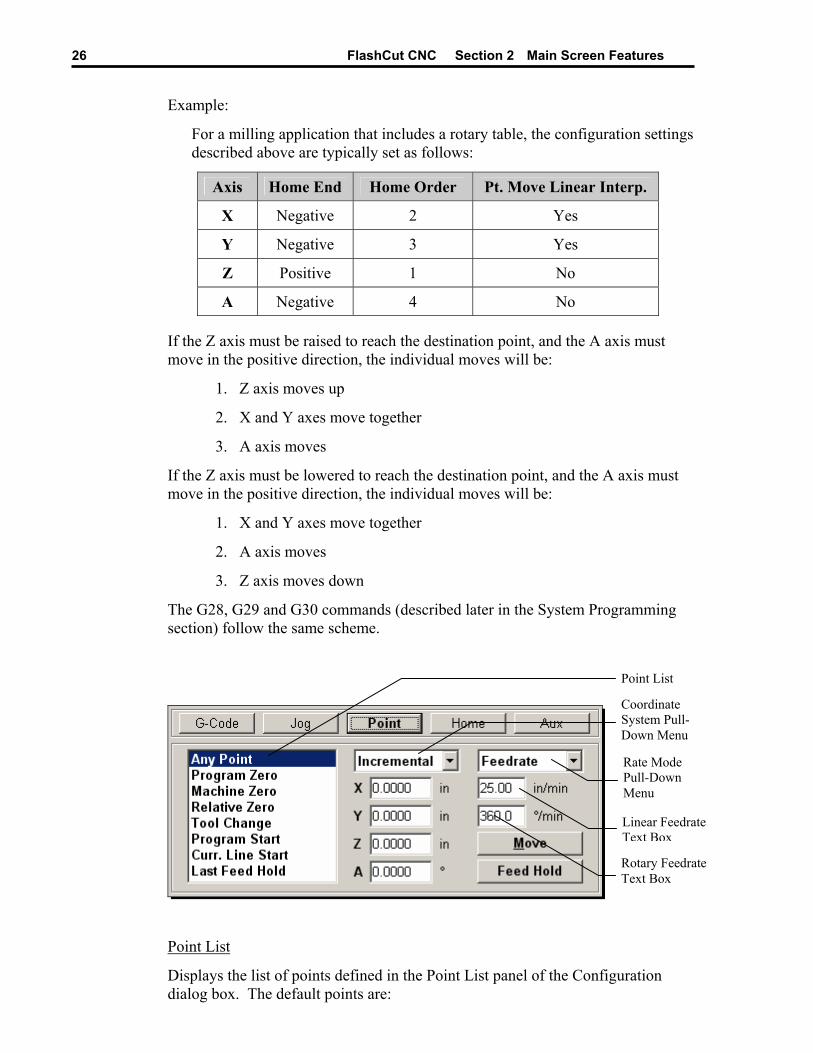
Example:
For a milling application that includes a rotary table, the configuration settings described above are typically set as follows:
Axis Home End Home Order Pt. Move Linear Interp.
X Negative 2 Yes
Y Negative 3 Yes
Z Positive 1 No
A Negative 4 No
If the Z axis must be raised to reach the destination point, and the A axis must move in the positive direction, the individual moves will be:
1. Z axis moves up
2. X and Y axes move together
3. A axis moves
If the Z axis must be lowered to reach the destination point, and the A axis must move in the positive direction, the individual moves will be:
1. X and Y axes move together
2. A axis moves
3. Z axis moves down
The G28, G29 and G30 commands (described later in the System Programming section) follow the same scheme.
Point List
Coordinate System Pull-Down Menu
Rate Mode Pull-Down Menu
Linear Feedrate Text Box
Rotary Feedrate Text Box
Point List
Displays the list of points defined in the Point List panel of the Configuration dialog box. The default points are:

FlashCut CNC Section 2 Main Screen Features 27
• Any Point – Moves to any XYZA point in the selected coordinate system.
• Program Zero – Moves to Program Zero.
• Machine Zero – Moves to Machine Zero (if defined).
• Relative Zero – Moves to Relative Zero.
• Tool Change – Moves to the G28 reference point specified in the Reference Point panel of the Configuration dialog box.
• Program Start Point – Moves to where the tool was located when the current G-Code program was started.
• Current Line Start Point – Moves to where the tool was located when the current G-Code line began execution. Also, after jumping to a new G-Code line, this value is the starting point for the G-Code line to which you jumped.
• Last Feed Hold Point – Moves to where the tool was located when G-Code execution was stopped by the Feed Hold button.
Note that you can select each item in the Point List using the keyboard as follows:
Any Point Shift + 1 Program Zero Shift + 2 Machine Zero Shift + 3 Relative Zero Shift + 4 Tool Change Position Shift + 5 Program Start Point Shift + 6 Current Line Start Point Shift + 7 Last Feed Hold Point Shift + 8
If you customize the Point List, the ‘Shift + n’ keyboard commands select the first 8 points listed, in numerical order (eg. ‘Shift + 1’ for the first point, ‘Shift + 2’ for the second point, and so on.)
Coordinate System Pull-Down Menu – The tool will move to the XYZA position in program coordinates, machine coordinates, relative coordinates, or incrementally from the current position of the tool, depending on the option you select.
Rate Mode Pull-Down Menu – You can set the travel rate by selecting one of the following:
• Rapid – The machine tool moves at the maximum feedrate allowed by your current maximum feedrate settings in the Feedrate/Ramping panel of the Configuration dialog box.
• Feedrate – The machine tool moves at the feedrate you enter in one of the feedrate text boxes.
Linear Feedrate Text Box – If Feedrate is selected in the Rate Mode pull-down menu, any moves that involve linear axes only will use this feedrate. When you
FlashCut CNC Section 2 Main Screen Features 28
startup FlashCut, this value defaults to the Point Feedrate-Linear field in the Feedrate/Ramping panel of the Configuration dialog box.
Rotary Feedrate Text Box – If Feedrate is selected in the Rate Mode pull-down menu, any moves that involve the ‘A’ axis will use this feedrate. When you startup FlashCut, this value defaults to the Point Feedrate-Rotary field in the Feedrate/Ramping panel of the Configuration dialog box.
Move Button – Executes the move.
Feed Hold Button – Stops execution of the move. Hitting any key on the keyboard (except Shift or Ctrl) also stops the move.
This button also stops automatic tool changing or tool length sensing.
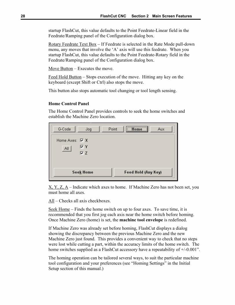
Home Control Panel The Home Control Panel provides controls to seek the home switches and establish the Machine Zero location.
X, Y, Z, A – Indicate which axes to home. If Machine Zero has not been set, you must home all axes.
All – Checks all axis checkboxes.
Seek Home – Finds the home switch on up to four axes. To save time, it is recommended that you first jog each axis near the home switch before homing. Once Machine Zero (home) is set, the machine tool envelope is redefined.
If Machine Zero was already set before homing, FlashCut displays a dialog showing the discrepancy between the previous Machine Zero and the new Machine Zero just found. This provides a convenient way to check that no steps were lost while cutting a part, within the accuracy limits of the home switch. The home switches supplied as a FlashCut accessory have a repeatability of +/-0.001”.
The homing operation can be tailored several ways, to suit the particular machine tool configuration and your preferences (see “Homing Settings” in the Initial Setup section of this manual.)
FlashCut CNC Section 2 Main Screen Features 29
Feed Hold Button – Stops the homing operation. Hitting any key on the keyboard (except Shift or Ctrl) also stops the operation.
This button also stops automatic tool changing or tool length sensing.
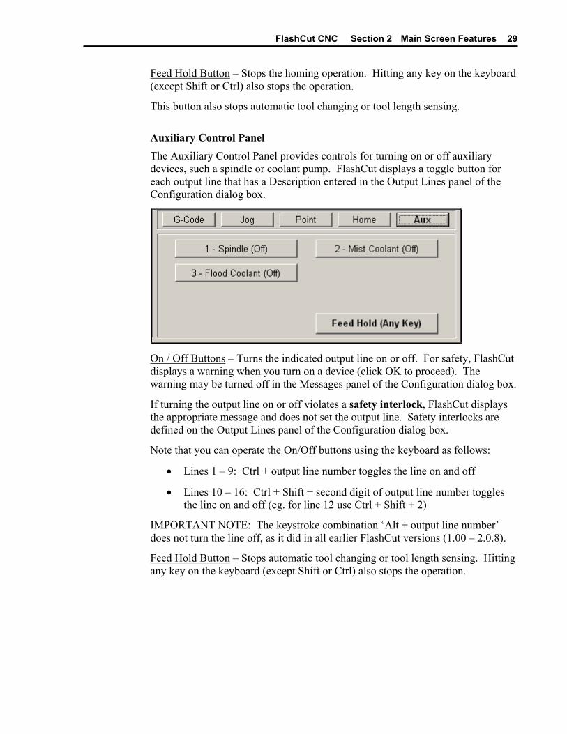
Auxiliary Control Panel The Auxiliary Control Panel provides controls for turning on or off auxiliary devices, such a spindle or coolant pump. FlashCut displays a toggle button for each output line that has a Description entered in the Output Lines panel of the Configuration dialog box.
On / Off Buttons – Turns the indicated output line on or off. For safety, FlashCut displays a warning when you turn on a device (click OK to proceed). The warning may be turned off in the Messages panel of the Configuration dialog box.
If turning the output line on or off violates a safety interlock, FlashCut displays the appropriate message and does not set the output line. Safety interlocks are defined on the Output Lines panel of the Configuration dialog box.
Note that you can operate the On/Off buttons using the keyboard as follows:
• Lines 1 – 9: Ctrl + output line number toggles the line on and off
• Lines 10 – 16: Ctrl + Shift + second digit of output line number toggles the line on and off (eg. for line 12 use Ctrl + Shift + 2)
IMPORTANT NOTE: The keystroke combination ‘Alt + output line number’ does not turn the line off, as it did in all earlier FlashCut versions (1.00 – 2.0.8).
Feed Hold Button – Stops automatic tool changing or tool length sensing. Hitting any key on the keyboard (except Shift or Ctrl) also stops the operation.
FlashCut CNC Section 2 Main Screen Features 30
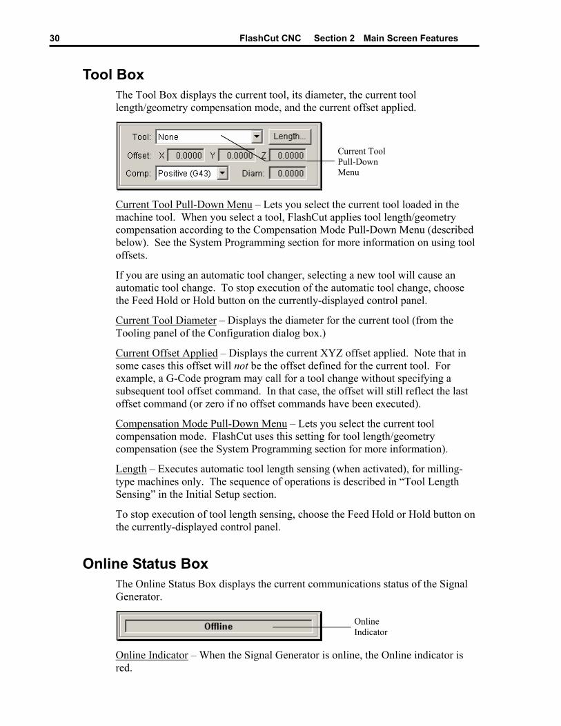
Tool Box The Tool Box displays the current tool, its diameter, the current tool length/geometry compensation mode, and the current offset applied.
Current Tool Pull-Down Menu
Current Tool Pull-Down Menu – Lets you select the current tool loaded in the machine tool. When you select a tool, FlashCut applies tool length/geometry compensation according to the Compensation Mode Pull-Down Menu (described below). See the System Programming section for more information on using tool offsets.
If you are using an automatic tool changer, selecting a new tool will cause an automatic tool change. To stop execution of the automatic tool change, choose the Feed Hold or Hold button on the currently-displayed control panel.
Current Tool Diameter – Displays the diameter for the current tool (from the Tooling panel of the Configuration dialog box.)
Current Offset Applied – Displays the current XYZ offset applied. Note that in some cases this offset will not be the offset defined for the current tool. For example, a G-Code program may call for a tool change without specifying a subsequent tool offset command. In that case, the offset will still reflect the last offset command (or zero if no offset commands have been executed).
Compensation Mode Pull-Down Menu – Lets you select the current tool compensation mode. FlashCut uses this setting for tool length/geometry compensation (see the System Programming section for more information).
Length – Executes automatic tool length sensing (when activated), for milling-type machines only. The sequence of operations is described in “Tool Length Sensing” in the Initial Setup section.
To stop execution of tool length sensing, choose the Feed Hold or Hold button on the currently-displayed control panel.
Online Status Box The Online Status Box displays the current communications status of the Signal Generator.
Online Indicator
Online Indicator – When the Signal Generator is online, the Online indicator is red.
FlashCut CNC Section 2 Main Screen Features 31
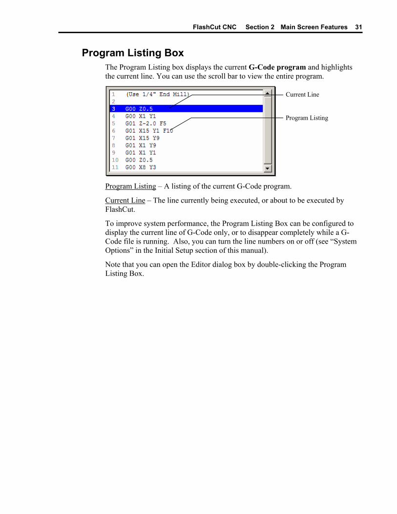
Program Listing Box The Program Listing box displays the current G-Code program and highlights the current line. You can use the scroll bar to view the entire program.
Current Line
Program Listing
Program Listing – A listing of the current G-Code program.
Current Line – The line currently being executed, or about to be executed by FlashCut.
To improve system performance, the Program Listing Box can be configured to display the current line of G-Code only, or to disappear completely while a G-Code file is running. Also, you can turn the line numbers on or off (see “System Options” in the Initial Setup section of this manual).
Note that you can open the Editor dialog box by double-clicking the Program Listing Box.


FlashCut CNC Section 3 Initial Setup 33
Section 3. Initial Setup This section describes how to set up FlashCut for use with your machine tool. It’s very important that the software and hardware are set up properly. Incorrect setup may cause the machine tool to behave in a potentially dangerous manner. Please read through this section carefully to gain a thorough understanding of how FlashCut controls your machine.
Windows Setup Since FlashCut is a real time control program, it must have full control of the operating system while running. It is very important that you do the following before running FlashCut:
Disable all screen savers and power management programs.
Make sure there are no background programs running such as back-up software and calendar reminders.
Make sure no other programs are open.
To Disable the Screen Saver
1. Choose Settings, then Control Panel from the Start Menu.
2. Double-click the Display icon.
3. Select the Screen Saver tab.
4. Select “(None)” from the Screen Saver pull-down menu.
5. Choose the Apply button.
6. Choose OK to exit.
Software Setup
The Configuration Files
All software settings are stored in three files:
• Setup file (extension “STP”): All machine-related settings
• Tooling file (extension “TLG”): All tooling settings
• User file (extension “USR”): All user preferences (not directly related to the machine or tooling)
FlashCut CNC Section 3 Initial Setup 34
Before you start running your machine, you’ll need to create the appropriate Setup file for your machine tool. Choose New Setup from the File menu and select the preconfigured Setup file that best matches your machine. If a preconfigured Setup file is not available for your machine, select FLASHCUT.STP. You can configure the setup parameters in this file for your machine tool.
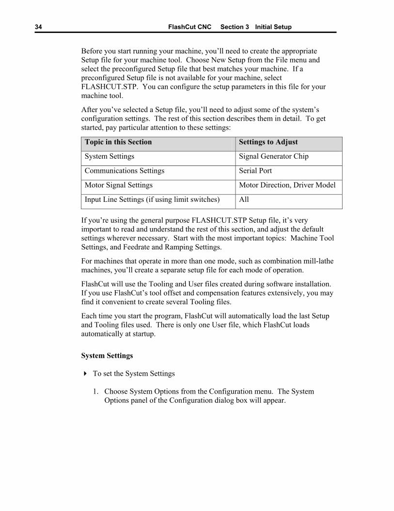
After you’ve selected a Setup file, you’ll need to adjust some of the system’s configuration settings. The rest of this section describes them in detail. To get started, pay particular attention to these settings:
Topic in this Section Settings to Adjust
System Settings Signal Generator Chip
Communications Settings Serial Port
Motor Signal Settings Motor Direction, Driver Model
Input Line Settings (if using limit switches) All
If you’re using the general purpose FLASHCUT.STP Setup file, it’s very important to read and understand the rest of this section, and adjust the default settings wherever necessary. Start with the most important topics: Machine Tool Settings, and Feedrate and Ramping Settings.
For machines that operate in more than one mode, such as combination mill-lathe machines, you’ll create a separate setup file for each mode of operation.
FlashCut will use the Tooling and User files created during software installation. If you use FlashCut’s tool offset and compensation features extensively, you may find it convenient to create several Tooling files.
Each time you start the program, FlashCut will automatically load the last Setup and Tooling files used. There is only one User file, which FlashCut loads automatically at startup.
System Settings
To set the System Settings
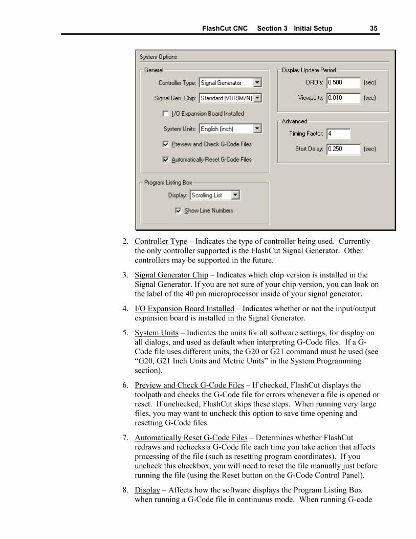
1. Choose System Options from the Configuration menu. The System Options panel of the Configuration dialog box will appear.
FlashCut CNC Section 3 Initial Setup 35
2. Controller Type – Indicates the type of controller being used. Currently
the only controller supported is the FlashCut Signal Generator. Other controllers may be supported in the future.
3. Signal Generator Chip – Indicates which chip version is installed in the Signal Generator. If you are not sure of your chip version, you can look on the label of the 40 pin microprocessor inside of your signal generator.
4. I/O Expansion Board Installed – Indicates whether or not the input/output expansion board is installed in the Signal Generator.
5. System Units – Indicates the units for all software settings, for display on all dialogs, and used as default when interpreting G-Code files. If a G-Code file uses different units, the G20 or G21 command must be used (see “G20, G21 Inch Units and Metric Units” in the System Programming section).
6. Preview and Check G-Code Files – If checked, FlashCut displays the toolpath and checks the G-Code file for errors whenever a file is opened or reset. If unchecked, FlashCut skips these steps. When running very large files, you may want to uncheck this option to save time opening and resetting G-Code files.
7. Automatically Reset G-Code Files – Determines whether FlashCut redraws and rechecks a G-Code file each time you take action that affects processing of the file (such as resetting program coordinates). If you uncheck this checkbox, you will need to reset the file manually just before running the file (using the Reset button on the G-Code Control Panel).
8. Display – Affects how the software displays the Program Listing Box when running a G-Code file in continuous mode. When running G-code
FlashCut CNC Section 3 Initial Setup 36
files with many short moves, the FlashCut software runs faster if you select “Current Line,” and runs fastest if you select “Nothing”.
9. Show Line Numbers – Determines whether or not FlashCut displays line numbers in the Program Listing Box.
10. Display Update Period – DRO’s – Determines how often the coordinates are updated in the DRO Box while the machine tool is moving. Higher values may increase performance on slower computers.
11. Display Update Period – Viewports – Determines how often the toolpath trace is updated in the Viewport Box while the machine tool is moving. Higher values may increase performance on slower computers.
12. Timing Factor – Sets the precision for timing on interpolated moves. The higher the number, the greater the precision and the lower the system’s top speed. For digital servo drivers, set this value to 2. For stepper drivers, set this value between 3 and 10.
13. Start Delay – Sets the duration of the delay that occurs when you click the Start button on the G-Code Control Panel (in Continuous mode only). This delay is required on slower PC’s to allow background processing to get well ahead of machine tool motion, which guarantees smooth motion when a file starts running.
Communications Settings
To set the Communications Settings
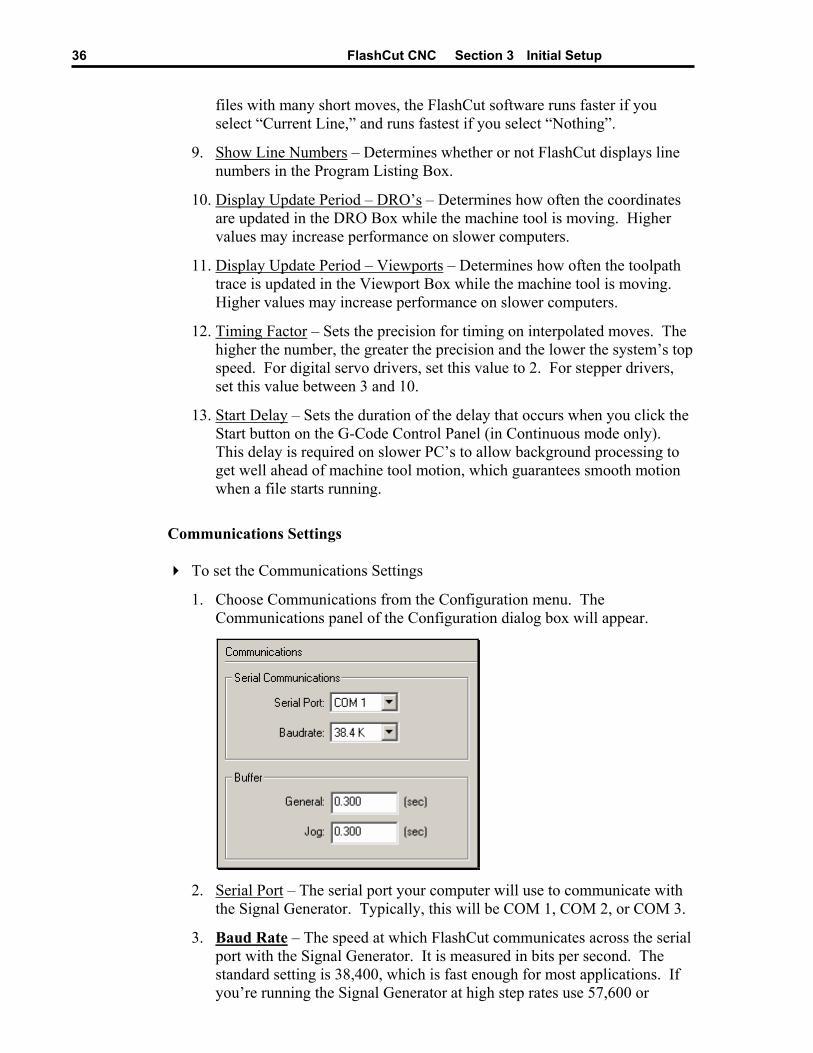
1. Choose Communications from the Configuration menu. The Communications panel of the Configuration dialog box will appear.
2. Serial Port – The serial port your computer will use to communicate with
the Signal Generator. Typically, this will be COM 1, COM 2, or COM 3.
3. Baud Rate – The speed at which FlashCut communicates across the serial port with the Signal Generator. It is measured in bits per second. The standard setting is 38,400, which is fast enough for most applications. If you’re running the Signal Generator at high step rates use 57,600 or
FlashCut CNC Section 3 Initial Setup 37
115,200. If you’re getting communications errors, try 9600 to help troubleshoot the problem (and move the machine only at slow speeds).
4. Buffer – General – Sets the buffer size on the Signal Generator for all operations except jogging in continuous mode. The buffer prevents system events (such as screen updates) from affecting motor movement on the machine tool. The larger the buffer, the less effect system events have on motor movement. The smaller the buffer, the more responsive the machine tool is to mouse clicks and keyboard commands. In most cases, the lag-time between the PC and the motor movement is imperceptible. The value can range from 0.01 to 1.0 seconds. Slower computers may require a higher value.
5. Buffer – Jog – Sets the buffer size on the Signal Generator for jogging in continuous mode. Typically this value is lower than the General value, to make the jog buttons more responsive.
Motor Signal Settings FlashCut provides three signals for motor drivers: step, direction, and enable. Different driver manufacturers have varying requirements for the polarity and timing of these signals. FlashCut provides the flexibility to tailor the motor signals to run any driver.
To set the Motor Signal Settings
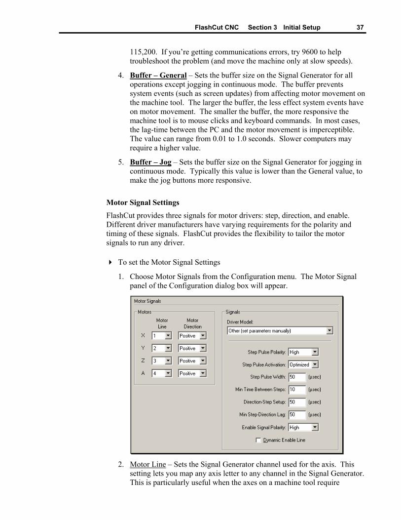
1. Choose Motor Signals from the Configuration menu. The Motor Signal panel of the Configuration dialog box will appear.
2. Motor Line – Sets the Signal Generator channel used for the axis. This
setting lets you map any axis letter to any channel in the Signal Generator. This is particularly useful when the axes on a machine tool require
FlashCut CNC Section 3 Initial Setup 38
different axis letters depending on the mode of operation (e.g. combination mill-lathe machines).
3. Motor Direction – Sets the direction of rotation for the motor. Depending on how a motor is wired, the same signal from the motor driver can turn it clockwise or counter clockwise. Use the jog buttons to make sure that a positive move in each axis on the screen corresponds to a positive move in each axis on the machine tool. Note that the direction of movement is defined as the direction of the tool relative to the workpiece. For example, on a typical milling machine, a positive X move (tool movement to the right) requires table movement to the left. If any direction is incorrect, change the Motor Direction from Positive to Negative (or vice-versa) to reverse the correspondence between the software and machine tool.
4. Driver Model – Sets the model of your motor driver box.
If you’re using a FlashCut driver box, the model number is printed on a sticker located on the back or bottom of the box. When you select your driver model, FlashCut enters the correct values for all other Signal settings (Step Pulse Polarity through Dynamic Enable Line). The fields are disabled and cannot be changed. If you need to change the values, choose Other (generally not necessary).
If you’re using non-FlashCut drivers, choose Other. This enables all fields, allowing you to enter the proper settings based on your motor driver requirements.
Some Signal fields only apply to the M202A and M202B Signal Generator chips. The M202B chip uses all the fields, providing the greatest flexibility for running any motor driver. See System Settings earlier in this section for more information on the Signal Generator chip setting.
FlashCut CNC Section 3 Initial Setup 39
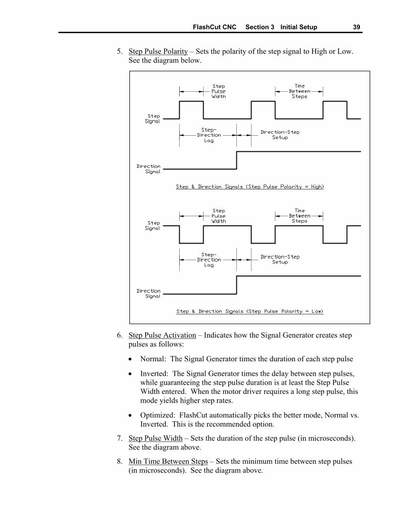
5. Step Pulse Polarity – Sets the polarity of the step signal to High or Low. See the diagram below.
6. Step Pulse Activation – Indicates how the Signal Generator creates step
pulses as follows:
• Normal: The Signal Generator times the duration of each step pulse
• Inverted: The Signal Generator times the delay between step pulses, while guaranteeing the step pulse duration is at least the Step Pulse Width entered. When the motor driver requires a long step pulse, this mode yields higher step rates.
• Optimized: FlashCut automatically picks the better mode, Normal vs. Inverted. This is the recommended option.
7. Step Pulse Width – Sets the duration of the step pulse (in microseconds). See the diagram above.
8. Min Time Between Steps – Sets the minimum time between step pulses (in microseconds). See the diagram above.
FlashCut CNC Section 3 Initial Setup 40
9. Direction-Step Setup – Sets the time between a direction change and the leading edge of the subsequent step pulse (in microseconds). See the diagram above.
10. Min Step-Direction Lag – Sets the minimum time from the leading edge of a step pulse to a subsequent direction change (in microseconds). See the diagram above.
11. Enable Signal Polarity – Sets the polarity of the enable signal. Choose High if the motor driver is enabled by a high signal, or Low if the motor driver is enabled by a low signal.
12. Dynamic Enable Line – Sets the behavior of the enable line. When checked, the enable line turns on when any axis is in motion, and turns off when all axes are idle. This box should generally be unchecked, as only certain drivers require dynamic enabling.
Machine Tool Settings
To set the Machine Tool Settings
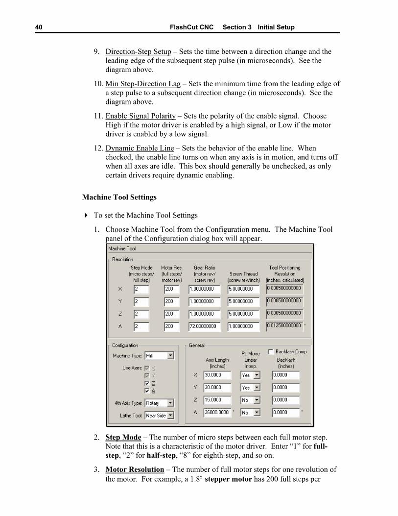
1. Choose Machine Tool from the Configuration menu. The Machine Tool panel of the Configuration dialog box will appear.
2. Step Mode – The number of micro steps between each full motor step.
Note that this is a characteristic of the motor driver. Enter “1” for full-step, “2” for half-step, “8” for eighth-step, and so on.
3. Motor Resolution – The number of full motor steps for one revolution of the motor. For example, a 1.8° stepper motor has 200 full steps per
FlashCut CNC Section 3 Initial Setup 41
revolution; a 0.9° stepper motor has 400 full steps per revolution, and so on. This number is a characteristic of the stepper motor and is independent of the motor driver or the Step Mode.
Note for Servo use, the product of the Step Mode and the Motor Resolution should equal the encoder pulses per servo motor revolution. For example, if you are using a 1000 line quadrature encoder and the FlashCut CNC Servo Drive is set at a step rate of 8:
Step Mode x Motor Resolution = 4 x 1000 / 8 = 500.
In this case the Step Mode can be 2 and the Motor Resolution can be 250.
4. Gear Ratio – The ratio of the number of stepper motor revolutions to drive screw revolutions due to any gears or pulleys between them. For direct drive, enter 1 in this box.
5. Screw Thread – The number of turns per unit length of the helical drive screw for each axis, or the turns per circumferential length of a pinion gear.
Lead Screw Example: A single threaded 0.05” pitch screw would have 20 turns per inch.
Pinion Gear Example: A 20 tooth pinion with a 0.2” tooth pitch would have 1 turn = 4.000” or 0.25 turns per inch.
For other types of drive mechanisms, enter the number of motor or pulley turns per unit length traveled by the axis.
6. Tool Positioning Resolution – The length of axis movement per motor step), automatically calculated from the Step Mode, Motor Resolution, Gear Ratio and Screw Thread.
7. Machine Type – Configures the software for Mill or Lathe mode. Mill mode may be used for any XY or XYZ table including routers, plasma cutters, and so on.
8. X, Y, Z, A Axes – Sets the axes in use on your machine tool. Check the appropriate check boxes.
9. 4th Axis Type – Sets the 4th axis as either linear or rotary. In FlashCut, a rotary 4th axis is assigned letter ‘A’, while a linear 4th axis is assigned the letter ‘W’. This manual will always refer to the 4th axis as the ‘A’ axis, but the ‘W’ alternative is always assumed.
10. Lathe Tool – Indicates which side of the lathe the tool is generally located. Your choice sets the orientation of the X+ direction, on the Jog Control Panel and in the Toolpath Viewport Box. This lets you match the direction on the screen to the actual direction of movement of the tool relative to you (for lathes only).
11. Axis Length – Sets the length of travel of each axis of your machine tool. You may want to define the axis length slightly smaller than the values

FlashCut CNC Section 3 Initial Setup 42
published by the machine tool manufacturer. This will leave some room for error.
12. Point Move Linear Interpolate – Determines if the motion for the axis will be included in the interpolated move for a Point move or G28/G29/G30 command (see “Point Control Panel” in the Main Screen Features section of this manual).
13. Backlash – Sets the amount of backlash for each axis. See the “Setting Up Backlash” section below for more information.
14. Comp – Determines whether or not FlashCut will use backlash compensation for all direction changes. Leave this check box unchecked for now. It’s discussed in the “Setting Up Backlash” section below.
Homing Settings
To set the Homing Settings
1. Choose Homing from the Configuration menu. The Homing panel of the Configuration dialog box will appear.
2. Home End – The end of the axis at Machine Zero (Home).
3. Home Order – The axis order for the homing operation. For safety, set the order so the initial homing move retracts the cutting tool away from the workpiece.
4. Home Axis – Determines whether or not an axis is included in the homing operation.
5. Home Switch Offset – The distance each axis backs away from the home switch after the switch is tripped during homing.
FlashCut CNC Section 3 Initial Setup 43
6. Homing Rate – The feedrate at which the machine tool will move when locating home switches (Seek Home button on the Home Control Panel, and G27 command).
7. Homing Tolerance – The distance allowed from the original Machine Zero location to the new Machine Zero location found during homing (used with the Hide Results if in Tolerance radio buttons).
8. Hide Results if in Tolerance – Tells FlashCut not to display the results of re-homing, if the discrepancy from the previous Machine Zero location is within the Homing Tolerance for all axes. There are separate settings for the Seek Home button (on the Home Control Panel) and the G27 command.
9. Reset Machine Zero – Tells FlashCut to automatically reset Machine Zero to the new location found, if the discrepancy from the previous Machine Zero location is within the Homing Tolerance for all axes. Note that the reset is automatic for the G27 command.
10. Always Display Results – Tells FlashCut to always display the results of re-homing, even if the discrepancy from the previous Machine Zero location is within the Homing Tolerance for all axes. There are separate settings for the Seek Home button (on the Home Control Panel) and the G27 command.
11. Maximum Homing Attempts – The maximum number of times the machine tool will re-home, while trying to get the discrepancy from the previous Machine Zero location within the Homing Tolerance for all axes.
Feedrate and Ramping Settings Every machine tool will vary as to how fast it can move each axis without losing steps. Losing steps means that even though the stepper motor gets the signal to move a step, it isn’t physically able to move the step, and accuracy is lost. The usual cause is insufficient torque at a given motor RPM. Since most stepper motors are open loop systems, there is no way of telling when a step is lost without physically measuring the movement of the axis and comparing that to the amount it should have moved. However, when it is not “over torqued”, a stepper motor is very reliable and accurate. For that reason, we highly recommend finding the maximum rates at which steps are not lost, both with and without ramping, and then limiting the maximum rates for each axis to about 70% of those values. Due to variations in the drive mechanism for each axis, make sure you do the following tests in all directions, and at several positions along each axis.
To Set the Start/Stop Feedrates
1. Choose Feedrate/Ramping from the Configuration menu. The Feedrate/Ramping panel of the Configuration dialog box will appear.

FlashCut CNC Section 3 Initial Setup 44
2. Enter 499 for the X axis Start/Stop Feedrate, and 500 for the Maximum
Feedrate, and then choose OK. (If your software settings do not allow you to set the Maximum Feedrate at 500, set it to the largest value your software allows, and set the Maximum Start/Stop feedrate to 1 less than that.) Note that all settings in these steps assume inch units, if your machine is set for metric units, you should multiply these settings by 25.
3. Choose the Point button in the Control Selection Box. Select Any Point in the Point List and Incremental from the Coordinate System pull-down menu. Enter 1.0 (or 25 if in metric mode) in the X text box. Choose Feedrate from the Rate Mode pull-down menu and enter a relatively slow feedrate (such as 5) in the Linear Feedrate text box. Make sure you have room to move the X axis 1 inch, and then choose Move.
4. If the motor slips, repeat this process with a slower feedrate. If the motor doesn’t slip, try a faster feedrate. Note that slight slippage can be detected by reading the values on the table feed hand-wheel or using a dial indicator.
5. Repeat this process until you find the highest feedrate that doesn’t cause motor slippage.
6. Now run the entire length of the X axis in both directions to make sure there is no slippage at any point on the entire axis.
7. Choose Feedrate/Ramping from the Configuration menu.
8. Enter 70% of the value you found in the Start/Stop Feedrate text box for the X axis, and then choose OK.
9. Repeat this process for all axes.
FlashCut CNC Section 3 Initial Setup 45
To Set the Maximum Feedrates
After finding the Start/Stop Feedrates, you’re ready to find the maximum feedrates achievable with ramping.
1. Choose Feedrate/Ramping from the Configuration menu. The Feedrate/Ramping panel of the Configuration dialog box will appear.
2. Enter 5000 full steps/sec/sec in the Ramping Rate text box for the X axis. (This is an average ramping rate.)
3. Leave the Start/Stop Feedrates at the values you found earlier. Leave the Maximum Feedrates at the very high number (500 in/min) and choose OK.
4. Choose the Point button on the Control Selection Box. Select Any Point in the Point List and Incremental from the Coordinate System pull-down menu. Enter 1.0 (or 25 if in metric mode) in the X text box. Choose Feedrate from the Rate Mode pull-down menu and enter a feedrate that is double the Start/Stop Feedrate for the X axis. Make sure you have room to move the X axis 1 inch, and then choose Move.
5. If the motor slips, repeat this process with a slower feedrate. If the motor doesn’t slip, try a faster feedrate. Note that slight slippage can be detected by reading the values on the table feed hand-wheel or using a dial indicator.
6. Repeat this process until you find the highest feedrate that doesn’t cause motor slippage.
7. Now run the entire length of the X axis in both directions to make sure there is no slippage at any point on the entire axis.
8. Choose Feedrate/Ramping from the Configuration menu.
9. Enter 70% of the highest no-slip feedrate you found in the X axis Maximum Feedrate text box.
10. Repeat this process for all axes.
To Set the Ramping Rate
Ramping Rates typically range from 1000 to 100000 full steps/sec/sec. Slower ramping rates require more time to ramp up to the maximum feedrate and to ramp down to a stop. This may become a potentially dangerous situation when using the Feed Hold button or jogging since the machine will take longer to come to a complete stop. The goal is to choose a fast ramping rate that will start and stop the tool responsively without losing steps. Fast ramping rates can also allow acceleration past resonant speeds of a stepper motor.
1. Choose Feedrate/Ramping from the Configuration menu. The Feedrate/Ramping panel of the Configuration dialog box will appear.
2. Enter 5000 full steps/sec/sec in the Ramping Rate text box for the X axis. (This is an average ramping rate.)

FlashCut CNC Section 3 Initial Setup 46
3. Leave the Start/Stop Feedrates and Maximum Feedrates at the values you found earlier and choose OK.
4. Choose the Point button on the Control Selection Box. Select Any Point in the Point List and Incremental from the Coordinate System pull-down menu. Enter 1.0 (or 25 if in metric mode) in the X text box. Choose Rapid from the Rate Mode pull-down menu. Make sure you have room to move the X axis 1 inch, and then choose Move. If the table doesn’t reach a continuous speed before ramping down to a stop, there isn’t enough room to fully ramp up and down, and you should increase the length of the move.
5. If the motor slips, repeat this process with a lower Ramping Rate. If the motor doesn’t slip, try a higher Ramping Rate. Note that slight slippage can be detected by reading the values on the table feed hand-wheel or using a dial indicator.
6. Repeat the above steps until you determine an optimal Ramping Rate for the X axis.
7. Choose Feedrate/Ramping from the Configuration menu.
8. Enter 70% of the highest no-slip ramping rate you found in the X axis Ramping Rate text box.
9. Repeat this process for all axes.
10. Note that once the optimal ramping rate is determined for each axis, you may want to re-test the Maximum Feedrates to see if they can be set any higher.
To Set the Direction Change Delay
The direction change delay is a brief pause that occurs when a motor changes direction. It gives the stepper motor time to settle and come to a complete rest before moving in the opposite direction. Note that the direction change delay is not used when a motor changes direction during circular interpolation or during a continuous contouring motion.
1. Write a G-Code file that goes back and forth on a given axis at the Start/Stop Feedrate. For example, if the Start/Stop Feedrate were 8:
G01 X2 F8
X0
X2
X0
2. Set the Direction Change Delay to 0.1 seconds for the given axis.
3. Run the program and notice if the motor loses steps. If so, increase the Direction Change Delay. Otherwise decrease the value.
FlashCut CNC Section 3 Initial Setup 47
4. Repeat the above process until you reach a reasonable delay time that eliminates any motor slippage. Note that this number is typically between 0.0 and 0.1 seconds. If you do not see any slippage at a delay of 0 seconds, it is recommended you enter at least 0.01 seconds.
5. Repeat the above process for all axes.
To Set the Continuous Contouring Feedrate Tolerance
Continuous contouring (also called “Look-ahead”) is a high performance feature that lets FlashCut run G-code files smoother and faster. The advantages of using continuous contouring are:
• Smooth transitions from one G-code line to the next if the two moves are in line with one another. There is no ramp down period and subsequent ramp up period. This minimizes witness marks, burning, melting and other quality problems sometimes encountered in machining. It also provides smooth, high speed motion for any other control application that requires it. A continuous smooth motion may span hundreds or thousands of G-code lines.
• High speed machining of point-to-point type G-Code files (composed of many short moves) used in complex 2D profiling and 3D surfacing. These G-Codes files can be executed much faster with continuous contouring.
To determine if two moves are lined up enough to allow a smooth transition without ramping, FlashCut calculates the change in speed of each motor through the transition, and compares that to the setting for Continuous Contouring Feedrate Tolerance. If the change in speed for each motor is less than the tolerance, FlashCut executes the two moves as part of the same smooth motion. Otherwise, FlashCut ramps down to end one motion and ramps up to begin another.
Any command that breaks the continuity of motion causes the machine tool to ramp down to a stop (such as any M code to control an auxiliary device, a G04 command for dwell, and so on).
A typical default setting for the Continuous Contouring Feedrate Tolerance is the Start/Stop Feedrate value. The higher you set the tolerance, the smoother a G-Code file will be executed (i.e., more moves will be linked together into smooth motions). If the values are set too high, loss of steps (stepper motor drivers) or servo errors (digital servo drivers) can occur. The best way to find an optimal setting is through trial and error. Incrementally raise the values and run demanding test files, checking for lost steps or servo errors.
Starting with FlashCut CNC 2.0, continuous contouring is always turned on. If you prefer that all moves ramp up and down, set the Continuous Contouring Feedrate Tolerance to zero for all axes.
FlashCut CNC Section 3 Initial Setup 48
To set the value:
1. Choose Feedrate/Ramping from the Configuration menu.
2. For each axis, enter the Start/Stop Feedrate, or a different setting as described above.
To Set the Jog Rates
1. Choose Feedrate/Ramping from the Configuration menu.
2. Fill in the Slow, Medium and Fast Linear Jog Rates (and the corresponding Rotary Jog Rates if your machine tool includes a rotary axis). Choose a Slow Jog Rate that will allow fine positioning of the machine tool (typically about 2-5 in/min). Choose a Fast Jog Rate that will move the tool quickly, yet allow you to remain in complete control without creating a dangerous situation. Note that the machine tool will not jog any faster than the Maximum Feedrate for each axis.
To Set the Maximum Arc Feedrate
Due to the computations involved during circular interpolation, an arc cannot be executed as fast as a line. For this reason, there is a user-configurable limitation for the maximum arc feedrate.
1. Write a G-Code program that moves in a circle at the Maximum Feedrate. For example, if the Maximum Feedrate were 100:
G00 X2 Y2
G02 X2 Y2 I1 J1 F100
2. Run the program and notice if either of the motors loses steps. If so, decrease the feedrate in the program.
3. Repeat the above process until neither motor loses any steps. Then enter the final feedrate from the program into the Maximum Arc Feedrate text box. If there was no loss of steps when the Maximum Feedrate was used, enter the Maximum Feedrate into the text box.
To Set the Point Feedrates – Linear and Rotary
The value entered in the Pt. Feedrate – Linear and Pt. Feedrate – Rotary text boxes will appear in the Linear Feedrate and Rotary Feedrate text boxes on the Point Control Panel, whenever you start the FlashCut program. Enter the feedrates you most commonly use for Point moves. A good starting point is the medium jog rate.
These feedrates are also used for positioning the machine after you’ve jumped to a new G-Code line (see “G-Code Control Panel” in the Main Screen Features section of this manual).

FlashCut CNC Section 3 Initial Setup 49
Setting Up Backlash Compensation
CNC control works best if there is little or no backlash on the machine tool. However, if your machine doesn’t have a zero-backlash drive mechanism (such as ball screws or anti-backlash nuts), FlashCut can compensate for the backlash.
To Set Backlash
1. Choose Machine Tool from the Configuration menu. The Machine Tool panel of the Configuration dialog box will appear.
2. Make sure the Comp checkbox is unchecked, and then choose OK.
3. Choose the Jog button on the Control Selection Box.
4. Drive the X axis in either direction at least 0.25” (to take out any backlash in that direction).
5. Zero the relative coordinates by choosing the Zero button next to the Relative label.
6. Choose the Step radio button. Jog the axis step by step in the opposite direction until you detect table movement (using a dial indicator).
7. The Relative coordinate X axis value is the amount of X axis backlash on your machine tool.
8. Write down this number and repeat the above process at different places along the X axis.
9. Choose Machine Tool from the Configuration menu. The Machine Tool panel of the Configuration dialog box will appear.
10. Record the average of all backlash values in the X axis Backlash text box. If you have no backlash on an axis, or if you don’t want backlash compensation on an axis, enter zero.
11. Repeat the above steps for each axis. When you’re finished, select the Comp checkbox and make sure there is a check in it.
Reference Point Settings Reference points provide a way to move the machine tool to a specific location defined in machine or program coordinates. They are accessible using the G28 and G30 commands (described in the “System Programming” section of this manual). Also, you may add reference points to the Point List displayed on the Point Control Panel.
To set the Reference Points
1. Choose Reference Points from the Configuration menu. The Reference Points panel of the Configuration dialog box will appear.

FlashCut CNC Section 3 Initial Setup 50
2. G-Code Cmd – This field identifies the command in a G-Code file that
moves the machine to the point (not editable).
3. Description – Enter a description for the point. For G28, the standard description is “Tool Change”.
4. Coordinate System – Choose between machine and program coordinates.
5. X, Y, Z, A Coordinates – Enter the coordinate for each axis. For G28, the standard location is Machine Zero (machine coordinates, all axis values set to zero).
Point List Settings You can customize the list of points displayed in the Point List on the Point Control Panel.
To customize the Point List
1. Choose Point List from the Configuration menu. The Point List panel of the Configuration dialog box will appear.

FlashCut CNC Section 3 Initial Setup 51
The list of Available Points includes (in order):
• System Points: Any Point, Program Zero, Machine Zero, Relative Zero, Program Start, Current Line Start, Last Feed Hold
• Reference Points: Any reference point that has a description entered (on the Reference Points panel)
• Tool Rack Positions: Any tool rack position with a value other than zero entered in any column (on the Tool Change panel)
2. Use the following buttons to modify the List on Point Control Panel.
Add – Adds the selected Available Point to the list
Up, Down – Moves the selected item in the list by one position
Remove – Removes the item from the list
Update Lists – Updates the Available Points list based on changes you’ve made on other configuration panels, and updates the names in the List on Point Control Panel.
3. Choose OK to exit the Configuration dialog. Then choose the Point button on the main screen to see your changes in the Point List. For more information, see “Point Control Panel” in the Main Screen Features section.
Fixture Offset Settings Fixture offsets provide a way to set the Program Zero location from within a G-Code file. They are activated using the G54-G59 and G54.1 commands (described in the System Programming section of this manual). The XYZA coordinates are defined in machine coordinates. These coordinates represent the offset from Machine Zero to the new Program Zero location.
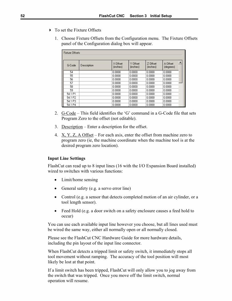
FlashCut CNC Section 3 Initial Setup 52
To set the Fixture Offsets
1. Choose Fixture Offsets from the Configuration menu. The Fixture Offsets panel of the Configuration dialog box will appear.
2. G-Code – This field identifies the ‘G’ command in a G-Code file that sets
Program Zero to the offset (not editable).
3. Description – Enter a description for the offset.
4. X, Y, Z, A Offset – For each axis, enter the offset from machine zero to program zero (ie, the machine coordinate when the machine tool is at the desired program zero location).
Input Line Settings
FlashCut can read up to 8 input lines (16 with the I/O Expansion Board installed) wired to switches with various functions:
• Limit/home sensing
• General safety (e.g. a servo error line)
• Control (e.g. a sensor that detects completed motion of an air cylinder, or a tool length sensor).
• Feed Hold (e.g. a door switch on a safety enclosure causes a feed hold to occur)
You can use each available input line however you choose, but all lines used must be wired the same way, either all normally open or all normally closed.
Please see the FlashCut CNC Hardware Guide for more hardware details, including the pin layout of the input line connector.
When FlashCut detects a tripped limit or safety switch, it immediately stops all tool movement without ramping. The accuracy of the tool position will most likely be lost at that point.
If a limit switch has been tripped, FlashCut will only allow you to jog away from the switch that was tripped. Once you move off the limit switch, normal operation will resume.
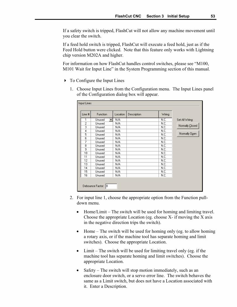
FlashCut CNC Section 3 Initial Setup 53
If a safety switch is tripped, FlashCut will not allow any machine movement until you clear the switch.
If a feed hold switch is tripped, FlashCut will execute a feed hold, just as if the Feed Hold button were clicked. Note that this feature only works with Lightning chip version M202A and higher.
For information on how FlashCut handles control switches, please see “M100, M101 Wait for Input Line” in the System Programming section of this manual.
To Configure the Input Lines
1. Choose Input Lines from the Configuration menu. The Input Lines panel of the Configuration dialog box will appear.
2. For input line 1, choose the appropriate option from the Function pull-
down menu.
• Home/Limit – The switch will be used for homing and limiting travel. Choose the appropriate Location (eg. choose X- if moving the X axis in the negative direction trips the switch).
• Home – The switch will be used for homing only (eg. to allow homing a rotary axis, or if the machine tool has separate homing and limit switches). Choose the appropriate Location.
• Limit – The switch will be used for limiting travel only (eg. if the machine tool has separate homing and limit switches). Choose the appropriate Location.
• Safety – The switch will stop motion immediately, such as an enclosure door switch, or a servo error line. The switch behaves the same as a Limit switch, but does not have a Location associated with it. Enter a Description.
FlashCut CNC Section 3 Initial Setup 54
• Control – The switch will be used for general control purposes, such as a ‘start’ button for the operator, or a tool length sensor. Enter a Description. See “M100 / M101” in the System Programming section for more details on use of control switches. See “Tool Length Sensing” below for more details on configuring tool length sensing.
• Feed Hold – The switch will cause a feed hold to occur.
• Unused – The input line is not used and will be ignored by the system.
3. Choose the appropriate setting from the Wiring pull-down menu. Use the Normally Open or Normally Closed button to set the wiring type for all input lines at once.
4. Repeat steps 1-3 for all available input lines (8 lines are standard, 16 lines are available if the I/O Expansion Board is installed).
5. Set the Debounce Factor. The higher the number, the longer the debounce time for all input lines. A typical setting is 8. If FlashCut is falsely reporting your switches as tripped (due to vibration or other causes), try raising the value.
Output Line Settings
FlashCut can control up to 8 output lines (16 with the I/O Expansion Board installed) to activate devices such as a spindle or coolant pump. You can control the output lines with the Auxiliary Control Panel, or with user-defined M codes. Please see the FlashCut CNC Hardware Guide for more hardware details including the pin layout of the output line connector.
To Configure the Output Lines
1. Choose Output Lines from the Configuration menu. The Output Lines panel of the Configuration dialog box will appear.
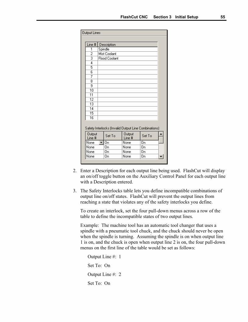
FlashCut CNC Section 3 Initial Setup 55
2. Enter a Description for each output line being used. FlashCut will display
an on/off toggle button on the Auxiliary Control Panel for each output line with a Description entered.
3. The Safety Interlocks table lets you define incompatible combinations of output line on/off states. FlashCut will prevent the output lines from reaching a state that violates any of the safety interlocks you define.
To create an interlock, set the four pull-down menus across a row of the table to define the incompatible states of two output lines.
Example: The machine tool has an automatic tool changer that uses a spindle with a pneumatic tool chuck, and the chuck should never be open when the spindle is turning. Assuming the spindle is on when output line 1 is on, and the chuck is open when output line 2 is on, the four pull-down menus on the first line of the table would be set as follows:
Output Line #: 1
Set To: On
Output Line #: 2
Set To: On
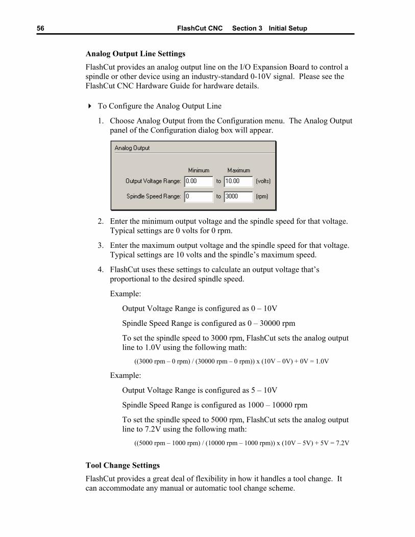
FlashCut CNC Section 3 Initial Setup 56
Analog Output Line Settings
FlashCut provides an analog output line on the I/O Expansion Board to control a spindle or other device using an industry-standard 0-10V signal. Please see the FlashCut CNC Hardware Guide for hardware details.
To Configure the Analog Output Line
1. Choose Analog Output from the Configuration menu. The Analog Output panel of the Configuration dialog box will appear.
2. Enter the minimum output voltage and the spindle speed for that voltage.
Typical settings are 0 volts for 0 rpm.
3. Enter the maximum output voltage and the spindle speed for that voltage. Typical settings are 10 volts and the spindle’s maximum speed.
4. FlashCut uses these settings to calculate an output voltage that’s proportional to the desired spindle speed.
Example:
Output Voltage Range is configured as 0 – 10V
Spindle Speed Range is configured as 0 – 30000 rpm
To set the spindle speed to 3000 rpm, FlashCut sets the analog output line to 1.0V using the following math:
((3000 rpm – 0 rpm) / (30000 rpm – 0 rpm)) x (10V – 0V) + 0V = 1.0V
Example:
Output Voltage Range is configured as 5 – 10V
Spindle Speed Range is configured as 1000 – 10000 rpm
To set the spindle speed to 5000 rpm, FlashCut sets the analog output line to 7.2V using the following math:
((5000 rpm – 1000 rpm) / (10000 rpm – 1000 rpm)) x (10V – 5V) + 5V = 7.2V
Tool Change Settings FlashCut provides a great deal of flexibility in how it handles a tool change. It can accommodate any manual or automatic tool change scheme.
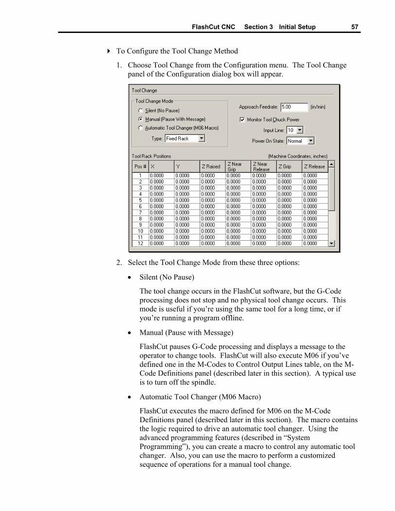
FlashCut CNC Section 3 Initial Setup 57
To Configure the Tool Change Method
1. Choose Tool Change from the Configuration menu. The Tool Change panel of the Configuration dialog box will appear.
2. Select the Tool Change Mode from these three options:
• Silent (No Pause)
The tool change occurs in the FlashCut software, but the G-Code processing does not stop and no physical tool change occurs. This mode is useful if you’re using the same tool for a long time, or if you’re running a program offline.
• Manual (Pause with Message)
FlashCut pauses G-Code processing and displays a message to the operator to change tools. FlashCut will also execute M06 if you’ve defined one in the M-Codes to Control Output Lines table, on the M-Code Definitions panel (described later in this section). A typical use is to turn off the spindle.
• Automatic Tool Changer (M06 Macro)
FlashCut executes the macro defined for M06 on the M-Code Definitions panel (described later in this section). The macro contains the logic required to drive an automatic tool changer. Using the advanced programming features (described in “System Programming”), you can create a macro to control any automatic tool changer. Also, you can use the macro to perform a customized sequence of operations for a manual tool change.

FlashCut CNC Section 3 Initial Setup 58
3. The rest of this section describes configuration for Automatic Tool Changer mode. If you chose Silent or Manual mode, you can skip to the next section.
4. From the Type drop-down menu, choose the type of automatic tool change:
• Fixed Rack – A stationary rack of tools is located somewhere in the machine envelope. The spindle is equipped with an automatic tool chuck. To pick up a tool, the machine moves to a rack position, closes the tool chuck and raises the Z axis. This is the most common automatic tool change method used on smaller machine tools. When you select this option, FlashCut automatically creates a standard M06 macro for you. You cannot edit the macro unless you switch to Custom Macro mode (below).
• Custom Macro – You’ll write a custom M06 macro to perform a tool change on other types of tool changers, or a customized manual tool change sequence. Also, you’ll use this mode if you want to start with the Fixed Rack macro, and tailor it for your tool changer.
If you chose Custom Macro, go to the M-Code Definitions panel and edit the existing M06 macro (or create a new one if one hasn’t been defined). See “M-Code Definitions” below for more details.
Any custom M06 macro must assign a value to a FlashCut system variable “#CurrTool”. The typical G-Code line for this is
#CurrTool = #NextTool
See “Advanced Programming Features” in the System Programming section to learn more about system variables and other advanced commands useful for controlling tool changers. You can skip the rest of this section, which describes the Fixed Rack tool change in detail.
5. The diagram below summarizes the sequence for the Fixed Rack tool change.
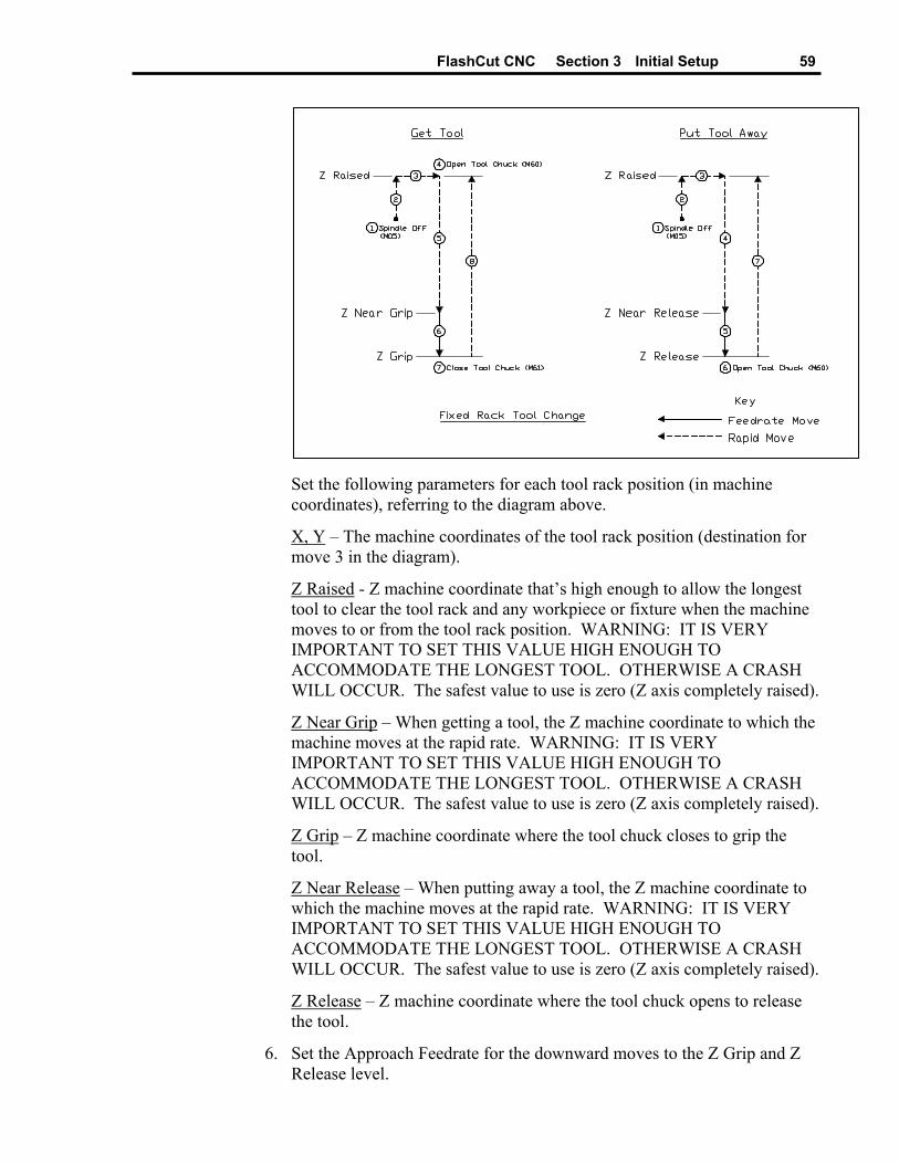
FlashCut CNC Section 3 Initial Setup 59
Set the following parameters for each tool rack position (in machine coordinates), referring to the diagram above.
X, Y – The machine coordinates of the tool rack position (destination for move 3 in the diagram).
Z Raised - Z machine coordinate that’s high enough to allow the longest tool to clear the tool rack and any workpiece or fixture when the machine moves to or from the tool rack position. WARNING: IT IS VERY IMPORTANT TO SET THIS VALUE HIGH ENOUGH TO ACCOMMODATE THE LONGEST TOOL. OTHERWISE A CRASH WILL OCCUR. The safest value to use is zero (Z axis completely raised).
Z Near Grip – When getting a tool, the Z machine coordinate to which the machine moves at the rapid rate. WARNING: IT IS VERY IMPORTANT TO SET THIS VALUE HIGH ENOUGH TO ACCOMMODATE THE LONGEST TOOL. OTHERWISE A CRASH WILL OCCUR. The safest value to use is zero (Z axis completely raised).
Z Grip – Z machine coordinate where the tool chuck closes to grip the tool.
Z Near Release – When putting away a tool, the Z machine coordinate to which the machine moves at the rapid rate. WARNING: IT IS VERY IMPORTANT TO SET THIS VALUE HIGH ENOUGH TO ACCOMMODATE THE LONGEST TOOL. OTHERWISE A CRASH WILL OCCUR. The safest value to use is zero (Z axis completely raised).
Z Release – Z machine coordinate where the tool chuck opens to release the tool.
6. Set the Approach Feedrate for the downward moves to the Z Grip and Z Release level.
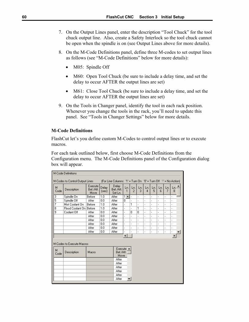
FlashCut CNC Section 3 Initial Setup 60
7. On the Output Lines panel, enter the description “Tool Chuck” for the tool chuck output line. Also, create a Safety Interlock so the tool chuck cannot be open when the spindle is on (see Output Lines above for more details).
8. On the M-Code Definitions panel, define three M-codes to set output lines as follows (see “M-Code Definitions” below for more details):
• M05: Spindle Off
• M60: Open Tool Chuck (be sure to include a delay time, and set the delay to occur AFTER the output lines are set)
• M61: Close Tool Chuck (be sure to include a delay time, and set the delay to occur AFTER the output lines are set)
9. On the Tools in Changer panel, identify the tool in each rack position. Whenever you change the tools in the rack, you’ll need to update this panel. See “Tools in Changer Settings” below for more details.
M-Code Definitions FlashCut let’s you define custom M-Codes to control output lines or to execute macros.
For each task outlined below, first choose M-Code Definitions from the Configuration menu. The M-Code Definitions panel of the Configuration dialog box will appear.

FlashCut CNC Section 3 Initial Setup 61
To define an M-code to control output lines
1. In the M Code text box type the number for the M-code that you want to define.
2. In the Description text box type a phrase that describes the action taken when this M-code is executed.
3. Choose Before or After from the Execute Before/After Move pull-down menu. If you choose Before and there is a machine tool move command on the same program line as the M-Code, FlashCut will execute the M-code before the move. If you chose After, FlashCut will execute the M-code after the move.
4. In the Delay text box, enter the duration for the delay that should occur when the output lines are set. For example, if the spindle motor takes about 3 seconds to reach full speed, this value should be at least 3.
5. Choose Before or After from the Delay Before/After Set Line pull-down menu. This setting tells FlashCut when to execute the delay, relative to setting the output lines.
6. In the Ln. # pull-down menus, choose the action for each line upon execution of the M-code. The choices are 1 for On, 0 for Off, or ‘-‘ to indicate the state of the line remains unchanged. You may use up to 8 lines standard, and up to 16 lines if the I/O Expansion Board is installed.
To define an M-Code to execute a macro
1. In the M Code text box type the number for the M-code that you want to define.
2. In the Description text box type a phrase that describes the action taken when this M-code is executed.
3. Click in the Macro field to display the down-arrow button. Click the down-arrow button to display the Edit M-Code Macro dialog. In this dialog, enter any number of G-Code lines. Whenever FlashCut encounters the M-Code in a G-Code program, these commands will be executed.
4. Choose Before or After from the Execute Before/After Move pull-down menu. If you choose Before and there is a machine tool move command on the same program line as the M-Code, FlashCut will execute the M-code before the move. If you chose After, FlashCut will execute the M-code after the move.
M-Code Execution Settings FlashCut let’s you choose one of several modes to automatically execute M-Codes.
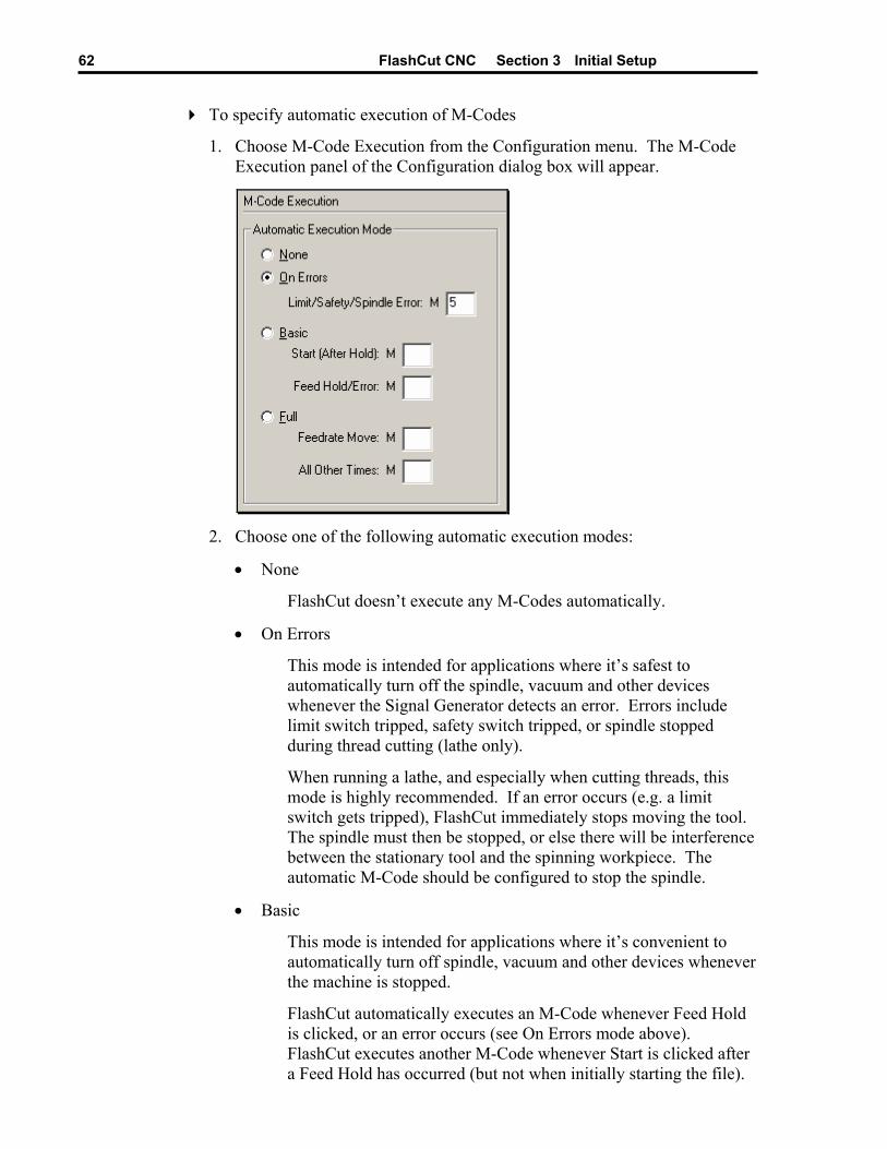
FlashCut CNC Section 3 Initial Setup 62
To specify automatic execution of M-Codes
1. Choose M-Code Execution from the Configuration menu. The M-Code Execution panel of the Configuration dialog box will appear.
2. Choose one of the following automatic execution modes:
• None
FlashCut doesn’t execute any M-Codes automatically.
• On Errors
This mode is intended for applications where it’s safest to automatically turn off the spindle, vacuum and other devices whenever the Signal Generator detects an error. Errors include limit switch tripped, safety switch tripped, or spindle stopped during thread cutting (lathe only).
When running a lathe, and especially when cutting threads, this mode is highly recommended. If an error occurs (e.g. a limit switch gets tripped), FlashCut immediately stops moving the tool. The spindle must then be stopped, or else there will be interference between the stationary tool and the spinning workpiece. The automatic M-Code should be configured to stop the spindle.
• Basic
This mode is intended for applications where it’s convenient to automatically turn off spindle, vacuum and other devices whenever the machine is stopped.
FlashCut automatically executes an M-Code whenever Feed Hold is clicked, or an error occurs (see On Errors mode above). FlashCut executes another M-Code whenever Start is clicked after a Feed Hold has occurred (but not when initially starting the file).
FlashCut CNC Section 3 Initial Setup 63
Note that you don’t need to fill in both M-Code fields; for example, you can specify a Feed Hold M-Code, and leave the Start (After Hold) field blank.
• Full
This mode is intended for applications where the controller must turn output lines on during feedrate moves and off during rapid moves. Applications include plasma cutting, laser cutting, waterjet cutting and liquid dispensing.
FlashCut executes the Feedrate Move M-Code before any feedrate move (G01, G02, G03), and before restarting a feedrate move after a Feed Hold.
FlashCut executes the All Other Times M-Code:
i. before any rapid move (G00)
ii. whenever Feed Hold is hit during a feedrate move
iii. at the end of the program if the program ends with a feedrate move
iv. when an error occurs (see On Errors mode above).
3. Enter an M-Code in the field(s) associated with the selected radio button. Each M-Code must be defined on the M-Code Definitions panel (in either table).
G-Code Settings
FlashCut lets you customize handling of some G-Code and M-Code commands.
To Configure G-Code Processing
1. Choose G-Codes from the Configuration menu. The G-Code panel of the Configuration dialog box will appear.
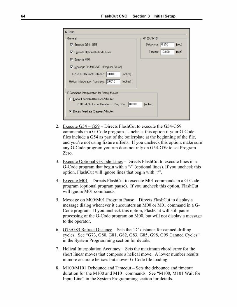
FlashCut CNC Section 3 Initial Setup 64
2. Execute G54 – G59 – Directs FlashCut to execute the G54-G59
commands in a G-Code program. Uncheck this option if your G-Code files include a G54 as part of the boilerplate at the beginning of the file, and you’re not using fixture offsets. If you uncheck this option, make sure any G-Code program you run does not rely on G54-G59 to set Program Zero.
3. Execute Optional G-Code Lines – Directs FlashCut to execute lines in a G-Code program that begin with a “/” (optional lines). If you uncheck this option, FlashCut will ignore lines that begin with “/”.
4. Execute M01 – Directs FlashCut to execute M01 commands in a G-Code program (optional program pause). If you uncheck this option, FlashCut will ignore M01 commands.
5. Message on M00/M01 Program Pause – Directs FlashCut to display a message dialog whenever it encounters an M00 or M01 command in a G-Code program. If you uncheck this option, FlashCut will still pause processing of the G-Code program on M00, but will not display a message to the operator.
6. G73/G83 Retract Distance – Sets the ‘D’ distance for canned drilling cycles. See “G73, G80, G81, G82, G83, G85, G98, G99 Canned Cycles” in the System Programming section for details.
7. Helical Interpolation Accuracy – Sets the maximum chord error for the short linear moves that compose a helical move. A lower number results in more accurate helixes but slower G-Code file loading.
8. M100/M101 Debounce and Timeout – Sets the debounce and timeout duration for the M100 and M101 commands. See “M100, M101 Wait for Input Line” in the System Programming section for details.
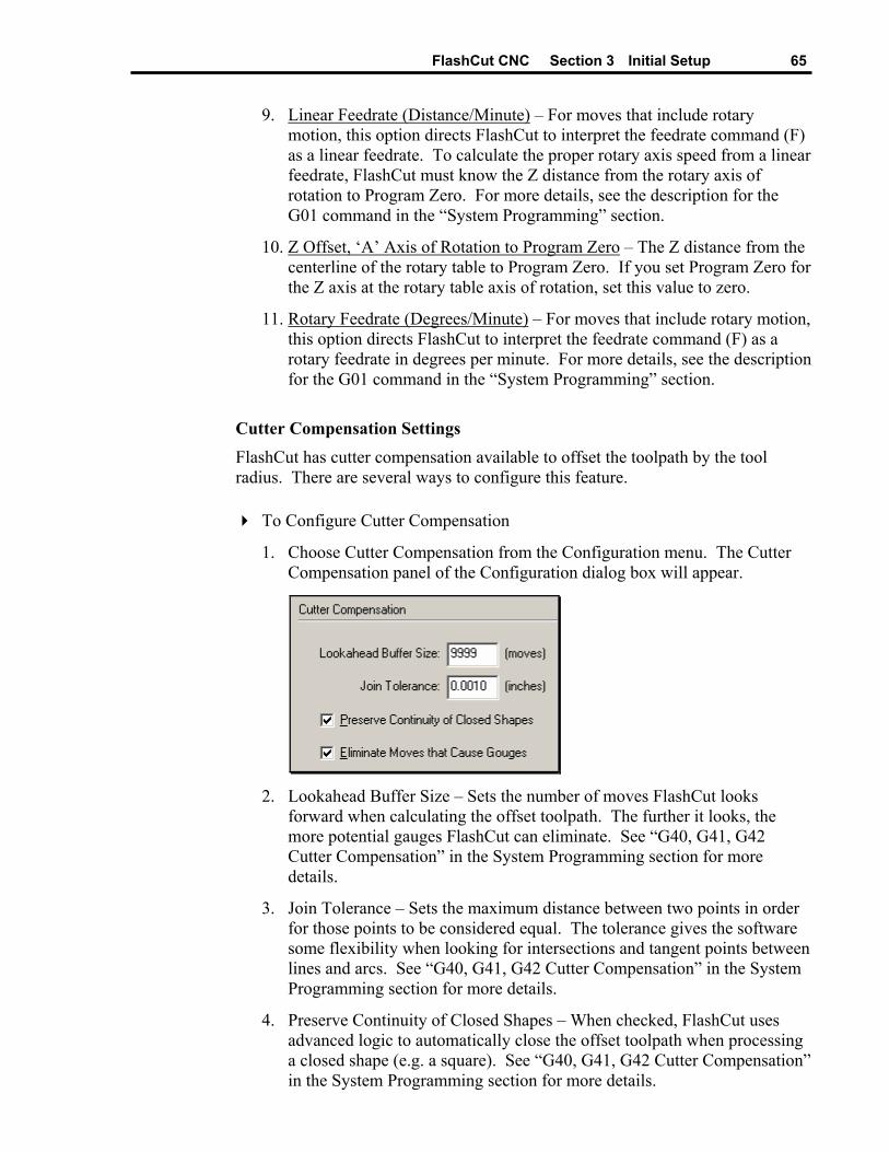
FlashCut CNC Section 3 Initial Setup 65
9. Linear Feedrate (Distance/Minute) – For moves that include rotary motion, this option directs FlashCut to interpret the feedrate command (F) as a linear feedrate. To calculate the proper rotary axis speed from a linear feedrate, FlashCut must know the Z distance from the rotary axis of rotation to Program Zero. For more details, see the description for the G01 command in the “System Programming” section.
10. Z Offset, ‘A’ Axis of Rotation to Program Zero – The Z distance from the centerline of the rotary table to Program Zero. If you set Program Zero for the Z axis at the rotary table axis of rotation, set this value to zero.
11. Rotary Feedrate (Degrees/Minute) – For moves that include rotary motion, this option directs FlashCut to interpret the feedrate command (F) as a rotary feedrate in degrees per minute. For more details, see the description for the G01 command in the “System Programming” section.
Cutter Compensation Settings FlashCut has cutter compensation available to offset the toolpath by the tool radius. There are several ways to configure this feature.
To Configure Cutter Compensation
1. Choose Cutter Compensation from the Configuration menu. The Cutter Compensation panel of the Configuration dialog box will appear.
2. Lookahead Buffer Size – Sets the number of moves FlashCut looks
forward when calculating the offset toolpath. The further it looks, the more potential gauges FlashCut can eliminate. See “G40, G41, G42 Cutter Compensation” in the System Programming section for more details.
3. Join Tolerance – Sets the maximum distance between two points in order for those points to be considered equal. The tolerance gives the software some flexibility when looking for intersections and tangent points between lines and arcs. See “G40, G41, G42 Cutter Compensation” in the System Programming section for more details.
4. Preserve Continuity of Closed Shapes – When checked, FlashCut uses advanced logic to automatically close the offset toolpath when processing a closed shape (e.g. a square). See “G40, G41, G42 Cutter Compensation” in the System Programming section for more details.
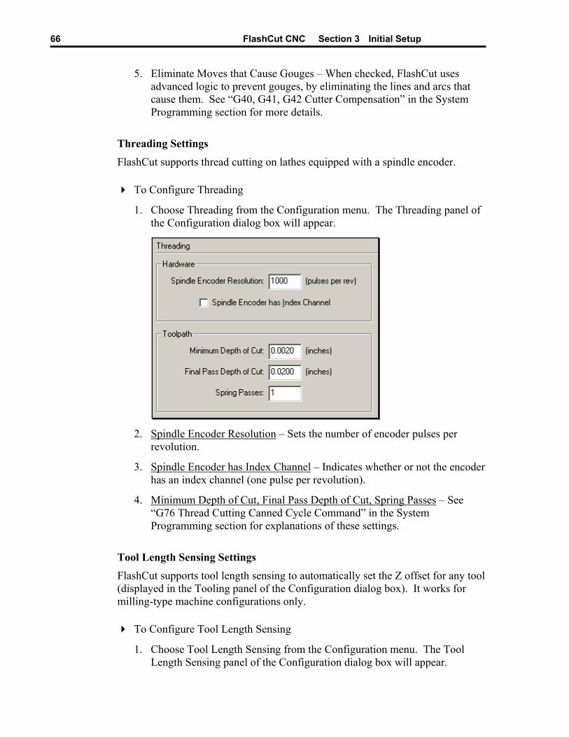
FlashCut CNC Section 3 Initial Setup 66
5. Eliminate Moves that Cause Gouges – When checked, FlashCut uses advanced logic to prevent gouges, by eliminating the lines and arcs that cause them. See “G40, G41, G42 Cutter Compensation” in the System Programming section for more details.
Threading Settings
FlashCut supports thread cutting on lathes equipped with a spindle encoder.
To Configure Threading
1. Choose Threading from the Configuration menu. The Threading panel of the Configuration dialog box will appear.
2. Spindle Encoder Resolution – Sets the number of encoder pulses per
revolution.
3. Spindle Encoder has Index Channel – Indicates whether or not the encoder has an index channel (one pulse per revolution).
4. Minimum Depth of Cut, Final Pass Depth of Cut, Spring Passes – See “G76 Thread Cutting Canned Cycle Command” in the System Programming section for explanations of these settings.
Tool Length Sensing Settings FlashCut supports tool length sensing to automatically set the Z offset for any tool (displayed in the Tooling panel of the Configuration dialog box). It works for milling-type machine configurations only.
To Configure Tool Length Sensing
1. Choose Tool Length Sensing from the Configuration menu. The Tool Length Sensing panel of the Configuration dialog box will appear.
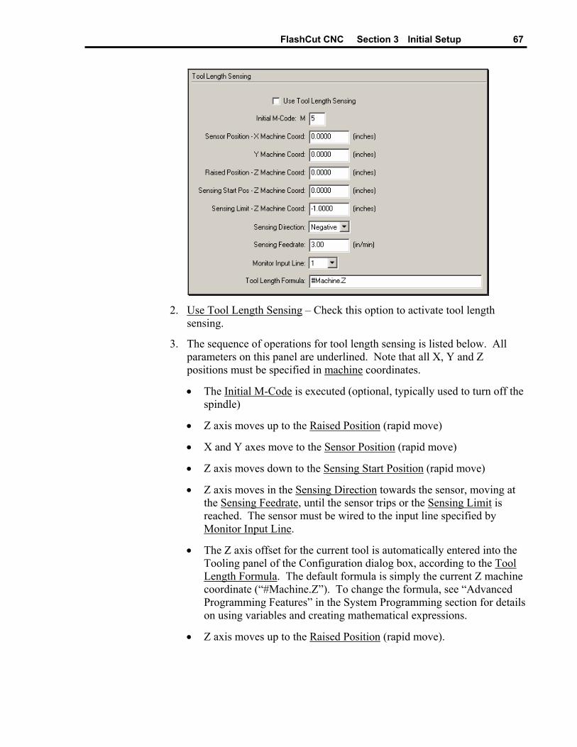
FlashCut CNC Section 3 Initial Setup 67
2. Use Tool Length Sensing – Check this option to activate tool length
sensing.
3. The sequence of operations for tool length sensing is listed below. All parameters on this panel are underlined. Note that all X, Y and Z positions must be specified in machine coordinates.
• The Initial M-Code is executed (optional, typically used to turn off the spindle)
• Z axis moves up to the Raised Position (rapid move)
• X and Y axes move to the Sensor Position (rapid move)
• Z axis moves down to the Sensing Start Position (rapid move)
• Z axis moves in the Sensing Direction towards the sensor, moving at the Sensing Feedrate, until the sensor trips or the Sensing Limit is reached. The sensor must be wired to the input line specified by Monitor Input Line.
• The Z axis offset for the current tool is automatically entered into the Tooling panel of the Configuration dialog box, according to the Tool Length Formula. The default formula is simply the current Z machine coordinate (“#Machine.Z”). To change the formula, see “Advanced Programming Features” in the System Programming section for details on using variables and creating mathematical expressions.
• Z axis moves up to the Raised Position (rapid move).
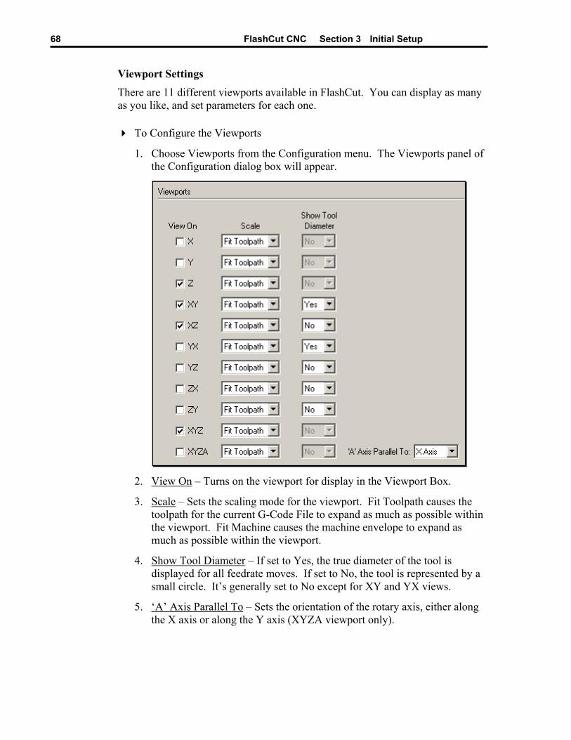
FlashCut CNC Section 3 Initial Setup 68
Viewport Settings
There are 11 different viewports available in FlashCut. You can display as many as you like, and set parameters for each one.
To Configure the Viewports
1. Choose Viewports from the Configuration menu. The Viewports panel of the Configuration dialog box will appear.
2. View On – Turns on the viewport for display in the Viewport Box.
3. Scale – Sets the scaling mode for the viewport. Fit Toolpath causes the toolpath for the current G-Code File to expand as much as possible within the viewport. Fit Machine causes the machine envelope to expand as much as possible within the viewport.
4. Show Tool Diameter – If set to Yes, the true diameter of the tool is displayed for all feedrate moves. If set to No, the tool is represented by a small circle. It’s generally set to No except for XY and YX views.
5. ‘A’ Axis Parallel To – Sets the orientation of the rotary axis, either along the X axis or along the Y axis (XYZA viewport only).
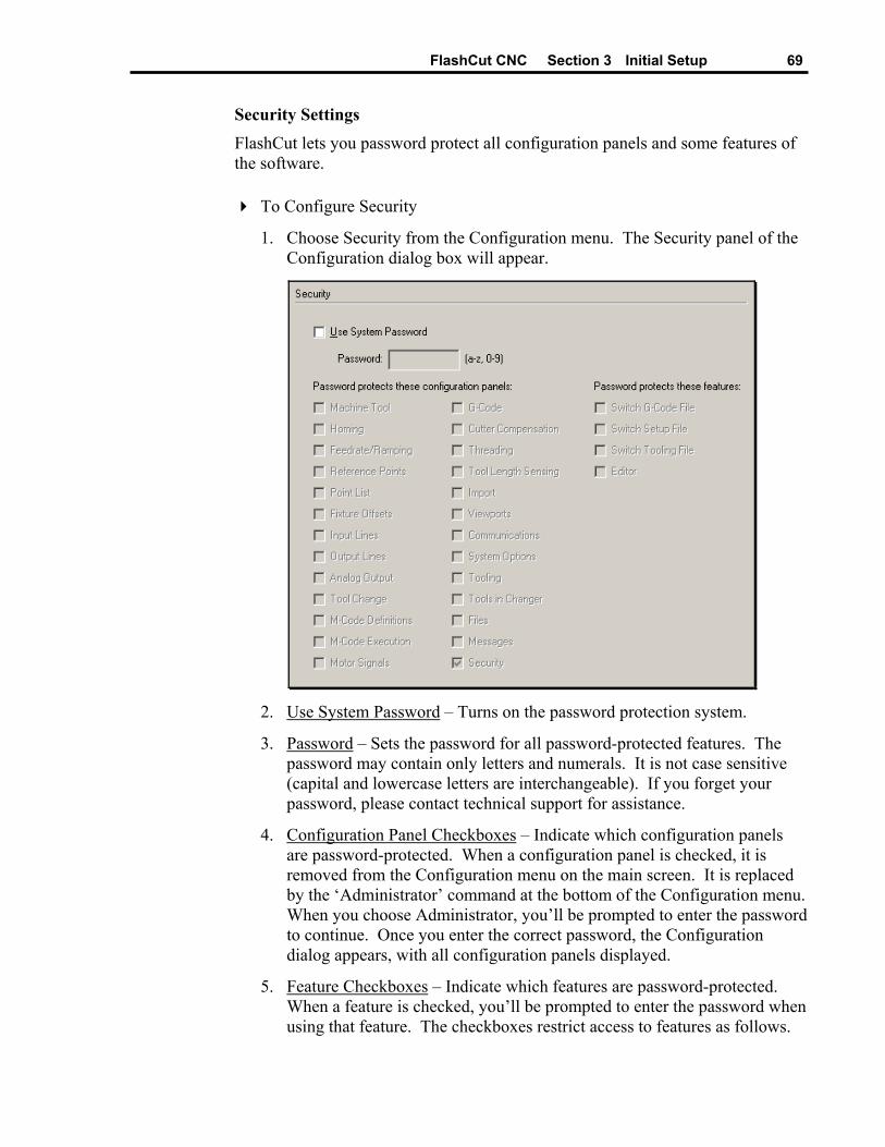
FlashCut CNC Section 3 Initial Setup 69
Security Settings
FlashCut lets you password protect all configuration panels and some features of the software.
To Configure Security
1. Choose Security from the Configuration menu. The Security panel of the Configuration dialog box will appear.
2. Use System Password – Turns on the password protection system.
3. Password – Sets the password for all password-protected features. The password may contain only letters and numerals. It is not case sensitive (capital and lowercase letters are interchangeable). If you forget your password, please contact technical support for assistance.
4. Configuration Panel Checkboxes – Indicate which configuration panels are password-protected. When a configuration panel is checked, it is removed from the Configuration menu on the main screen. It is replaced by the ‘Administrator’ command at the bottom of the Configuration menu. When you choose Administrator, you’ll be prompted to enter the password to continue. Once you enter the correct password, the Configuration dialog appears, with all configuration panels displayed.
5. Feature Checkboxes – Indicate which features are password-protected. When a feature is checked, you’ll be prompted to enter the password when using that feature. The checkboxes restrict access to features as follows.
FlashCut CNC Section 3 Initial Setup 70
Switch G-Code File
File : New G-Code (Main Screen & Editor)
File : Open G-Code (Main Screen & Editor)
File : Close G-Code (Main Screen & Editor)
File : Recently Used Files (Main Screen & Editor)
File : Editor (Main Screen, only when there’s no file open)
File : Import DXF (Main Screen)
File : Save G-Code As (Editor)
Switch Setup File
File : New Setup
File : Open Setup
File : Save Setup As
Switch Tooling File
File : New Tooling
File : Open Tooling
File : Save Tooling As
Editor
File : Editor
Tooling Settings Each tooling file contains settings for up to 100 tools. Each tool has an associated tool number, description, diameter and XYZ offset. The diameter is used by the cutter compensation commands (G41 and G42). The XYZ offset is used by the tool length/geometry compensation commands (G43 and G44).
To Set Up the Tool Library
1. Choose Tooling from the Configuration menu. The Tooling panel of the Configuration dialog box will appear.
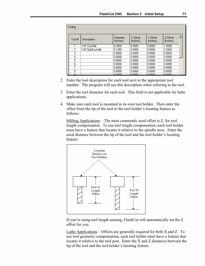
FlashCut CNC Section 3 Initial Setup 71
2. Enter the tool description for each tool next to the appropriate tool
number. The program will use this description when referring to the tool.
3. Enter the tool diameter for each tool. This field is not applicable for lathe applications.
4. Make sure each tool is mounted in its own tool holder. Then enter the offset from the tip of the tool to the tool holder’s locating feature as follows:
Milling Applications – The most commonly used offset is Z, for tool length compensation. To use tool length compensation, each tool holder must have a feature that locates it relative to the spindle nose. Enter the axial distance between the tip of the tool and the tool holder’s locating feature.
Tool #2 Length Offset
Locating Surfaces on
Tool Holders
Tool #1 Length Offset
If you’re using tool length sensing, FlashCut will automatically set the Z offset for you.
Lathe Applications – Offsets are generally required for both X and Z. To use tool geometry compensation, each tool holder must have a feature that locates it relative to the tool post. Enter the X and Z distances between the tip of the tool and the tool holder’s locating feature.
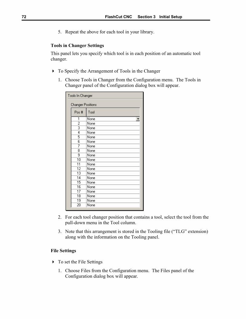
FlashCut CNC Section 3 Initial Setup 72
5. Repeat the above for each tool in your library.
Tools in Changer Settings This panel lets you specify which tool is in each position of an automatic tool changer.
To Specify the Arrangement of Tools in the Changer
1. Choose Tools in Changer from the Configuration menu. The Tools in Changer panel of the Configuration dialog box will appear.
2. For each tool changer position that contains a tool, select the tool from the
pull-down menu in the Tool column.
3. Note that this arrangement is stored in the Tooling file (“TLG” extension) along with the information on the Tooling panel.
File Settings
To set the File Settings
1. Choose Files from the Configuration menu. The Files panel of the Configuration dialog box will appear.
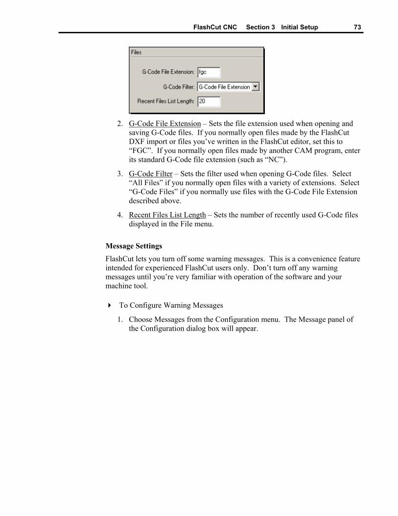
FlashCut CNC Section 3 Initial Setup 73
2. G-Code File Extension – Sets the file extension used when opening and
saving G-Code files. If you normally open files made by the FlashCut DXF import or files you’ve written in the FlashCut editor, set this to “FGC”. If you normally open files made by another CAM program, enter its standard G-Code file extension (such as “NC”).
3. G-Code Filter – Sets the filter used when opening G-Code files. Select “All Files” if you normally open files with a variety of extensions. Select “G-Code Files” if you normally use files with the G-Code File Extension described above.
4. Recent Files List Length – Sets the number of recently used G-Code files displayed in the File menu.
Message Settings FlashCut lets you turn off some warning messages. This is a convenience feature intended for experienced FlashCut users only. Don’t turn off any warning messages until you’re very familiar with operation of the software and your machine tool.
To Configure Warning Messages
1. Choose Messages from the Configuration menu. The Message panel of the Configuration dialog box will appear.
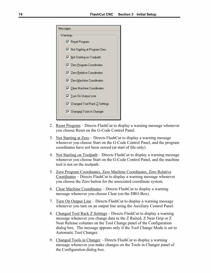
FlashCut CNC Section 3 Initial Setup 74
2. Reset Program – Directs FlashCut to display a warning message whenever
you choose Reset on the G-Code Control Panel.
3. Not Starting at Zero – Directs FlashCut to display a warning message whenever you choose Start on the G-Code Control Panel, and the program coordinates have not been zeroed (at start of file only).
4. Not Starting on Toolpath – Directs FlashCut to display a warning message whenever you choose Start on the G-Code Control Panel, and the machine tool is not on the toolpath.
5. Zero Program Coordinates, Zero Machine Coordinates, Zero Relative Coordinates – Directs FlashCut to display a warning message whenever you choose the Zero button for the associated coordinate system.
6. Clear Machine Coordinates – Directs FlashCut to display a warning message whenever you choose Clear (on the DRO Box).
7. Turn On Output Line – Directs FlashCut to display a warning message whenever you turn on an output line using the Auxiliary Control Panel.
8. Changed Tool Rack Z Settings – Directs FlashCut to display a warning message whenever you change data in the Z Raised, Z Near Grip or Z Near Release columns on the Tool Change panel of the Configuration dialog box. The message appears only if the Tool Change Mode is set to Automatic Tool Changer.
9. Changed Tools in Changer – Directs FlashCut to display a warning message whenever you make changes on the Tools in Changer panel of the Configuration dialog box.

FlashCut CNC Section 3 Initial Setup 75
Setting Machine Zero
FlashCut lets you set Machine Zero two ways: Homing to switches or using the Zero button. Either method establishes the machine tool envelope, which provides these benefits:
• The software will safely ramp down the machine tool to a complete stop at the defined limits of the machine tool envelope.
• The software checks each G-Code file before running to make sure the toolpath fits completely within the machine tool envelope.
It’s better to home to switches since it provides these added benefits:
• It’s much more convenient, since FlashCut can find Machine Zero automatically.
• You can establish Machine Zero at the same repeatable location anytime you like (within the repeatability tolerance of the switch). A repeatable Machine Zero lets you restart unfinished jobs, and reliably position the tool relative to work-holding fixtures.
• You can use the homing process to check for accuracy of the machine tool’s position.
To Set Machine Zero by Homing to Switches
1. Make sure you’ve correctly entered the homing-related setup parameters described in the “Machine Tool Settings”, “Homing Settings” and “Input Line Settings” sections above.
2. Choose the Home button on the Control Selection Box.
3. If Machine Zero has not been set, make sure all axis checkboxes are checked.
4. Choose the Seek Home button. One axis at a time, FlashCut drives the axis until it finds and backs off the switch. To stop the process, choose the Feed Hold button, or hit any key on the keyboard besides Ctrl or Shift.
5. If Machine Zero was already set before homing, FlashCut displays a dialog showing the discrepancy between the previous Machine Zero and the new Machine Zero just found. Choose Yes if you want to use the new Machine Zero just found, or No if you want to keep the existing Machine Zero.
6. If you chose Yes, FlashCut zeros the machine coordinates and displays the Machine Tool Envelope in the Toolpath Viewport Box.
To Set Machine Zero Using the Zero Button
1. Make sure you’ve correctly entered the homing-related setup parameters described in the “Machine Tool Settings” and “Homing Settings” section above.

FlashCut CNC Section 3 Initial Setup 76
2. Choose the Jog button on the Control Selection Box.
3. Jog the tool to the home end of each axis (as defined on the Homing panel of the Configuration dialog box). Move each axis to within a short distance of its physical limit.
4. If this is the first time you’re setting Machine Zero on your machine, it might be helpful to scratch a reference line or attach a vernier scale to two adjacent moving parts on each axis. This will help you find the same home position again in the future.
5. Choose the Zero button next to the Machine label in the DRO Box. When the confirmation dialog appears, choose Yes (see “Message Settings” above for details on suppressing this dialog if desired).
6. If Machine Zero was already set, FlashCut displays a dialog showing the discrepancy between the previous Machine Zero and the new Machine Zero just set. Choose Yes if you want to use the new Machine Zero just set, or No if you want to keep the existing Machine Zero.
7. If you chose Yes, FlashCut zeros the machine coordinates and displays the machine tool envelope in the Toolpath Viewport Box.
FlashCut CNC Section 4 System Programming 77
Section 4. System Programming FlashCut supports ANSI standard G-Code to control machine tool movement. This section describes how to create and open G-Code files, and the G-Codes supported.
There are three ways you can open or create G-Code files:
• Open an existing G-Code file created by a CAM program, FlashCut or any other source.
• Import a DXF file created by a CAD or drawing program.
• Write a G-Code program directly in the FlashCut editor.
Opening a G-Code Program
To open an existing program
1. Choose Open G-Code from the File menu. The Open G-Code File dialog box appears.
2. Navigate to the G-Code file you wish to open.
3. Double-click the file name, or click on the file name and choose OK.
Importing a DXF File FlashCut provides a very useful 2D DXF import feature. The DXF import automatically arranges all lines and arcs that have common endpoints into features. The entire toolpath is then optimized to reduce total machining time for the part. The DXF import assumes the part surface is at a Z program height of 0.0. All geometry is to be treated as either holes or cutter paths with no offsets.
To import a DXF file
1. Choose Import DXF from the File menu. The Open dialog box appears.
2. Navigate to the DXF file you wish to import.
3. Double-click the file name, or click on the file name and choose OK.
4. The Save As dialog box appears, asking you the name of the new G-Code file created by the DXF import. By default, it will use the DXF file name with an “FGC” extension in the same drive and folder in which the DXF file resides. If this is acceptable, choose OK. Otherwise, you can rename the file and/or choose an alternate folder.
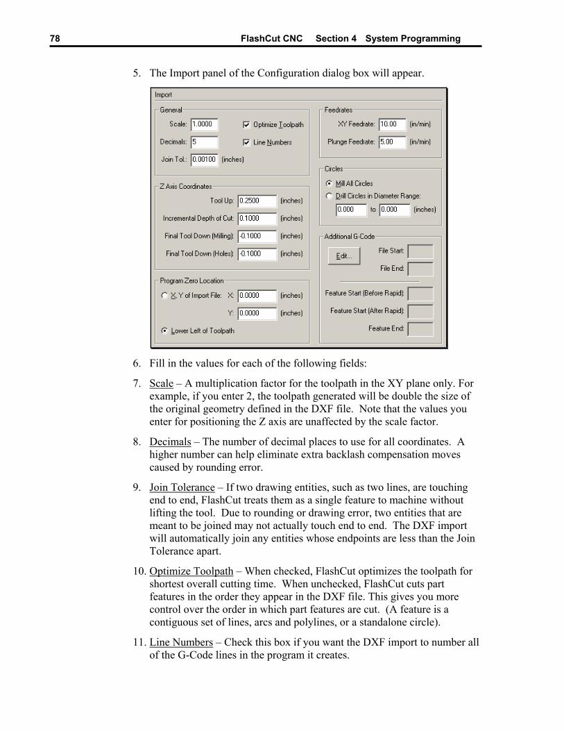
FlashCut CNC Section 4 System Programming 78
5. The Import panel of the Configuration dialog box will appear.
6. Fill in the values for each of the following fields:
7. Scale – A multiplication factor for the toolpath in the XY plane only. For example, if you enter 2, the toolpath generated will be double the size of the original geometry defined in the DXF file. Note that the values you enter for positioning the Z axis are unaffected by the scale factor.
8. Decimals – The number of decimal places to use for all coordinates. A higher number can help eliminate extra backlash compensation moves caused by rounding error.
9. Join Tolerance – If two drawing entities, such as two lines, are touching end to end, FlashCut treats them as a single feature to machine without lifting the tool. Due to rounding or drawing error, two entities that are meant to be joined may not actually touch end to end. The DXF import will automatically join any entities whose endpoints are less than the Join Tolerance apart.
10. Optimize Toolpath – When checked, FlashCut optimizes the toolpath for shortest overall cutting time. When unchecked, FlashCut cuts part features in the order they appear in the DXF file. This gives you more control over the order in which part features are cut. (A feature is a contiguous set of lines, arcs and polylines, or a standalone circle).
11. Line Numbers – Check this box if you want the DXF import to number all of the G-Code lines in the program it creates.
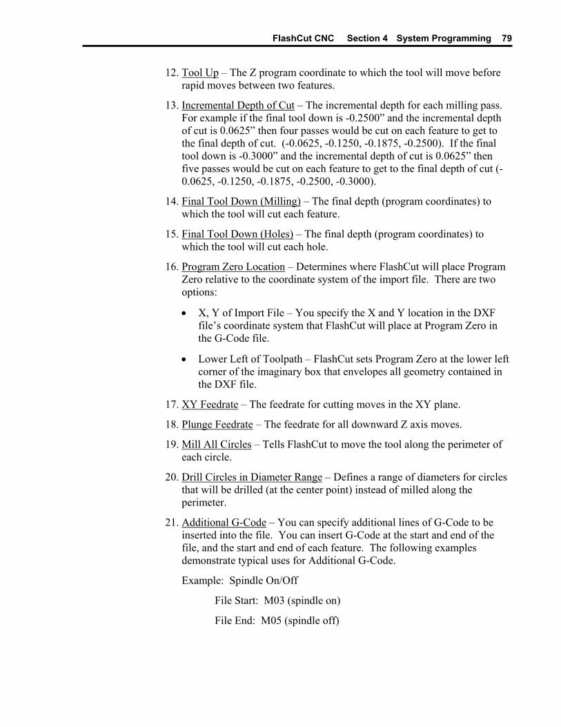
FlashCut CNC Section 4 System Programming 79
12. Tool Up – The Z program coordinate to which the tool will move before rapid moves between two features.
13. Incremental Depth of Cut – The incremental depth for each milling pass. For example if the final tool down is -0.2500” and the incremental depth of cut is 0.0625” then four passes would be cut on each feature to get to the final depth of cut. (-0.0625, -0.1250, -0.1875, -0.2500). If the final tool down is -0.3000” and the incremental depth of cut is 0.0625” then five passes would be cut on each feature to get to the final depth of cut (-0.0625, -0.1250, -0.1875, -0.2500, -0.3000).
14. Final Tool Down (Milling) – The final depth (program coordinates) to which the tool will cut each feature.
15. Final Tool Down (Holes) – The final depth (program coordinates) to which the tool will cut each hole.
16. Program Zero Location – Determines where FlashCut will place Program Zero relative to the coordinate system of the import file. There are two options:
• X, Y of Import File – You specify the X and Y location in the DXF file’s coordinate system that FlashCut will place at Program Zero in the G-Code file.
• Lower Left of Toolpath – FlashCut sets Program Zero at the lower left corner of the imaginary box that envelopes all geometry contained in the DXF file.
17. XY Feedrate – The feedrate for cutting moves in the XY plane.
18. Plunge Feedrate – The feedrate for all downward Z axis moves.
19. Mill All Circles – Tells FlashCut to move the tool along the perimeter of each circle.
20. Drill Circles in Diameter Range – Defines a range of diameters for circles that will be drilled (at the center point) instead of milled along the perimeter.
21. Additional G-Code – You can specify additional lines of G-Code to be inserted into the file. You can insert G-Code at the start and end of the file, and the start and end of each feature. The following examples demonstrate typical uses for Additional G-Code.
Example: Spindle On/Off
File Start: M03 (spindle on)
File End: M05 (spindle off)
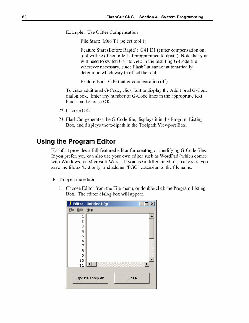
FlashCut CNC Section 4 System Programming 80
Example: Use Cutter Compensation
File Start: M06 T1 (select tool 1)
Feature Start (Before Rapid): G41 D1 (cutter compensation on, tool will be offset to left of programmed toolpath) Note that you will need to switch G41 to G42 in the resulting G-Code file wherever necessary, since FlashCut cannot automatically determine which way to offset the tool.
Feature End: G40 (cutter compensation off)
To enter additional G-Code, click Edit to display the Additional G-Code dialog box. Enter any number of G-Code lines in the appropriate text boxes, and choose OK.
22. Choose OK.
23. FlashCut generates the G-Code file, displays it in the Program Listing Box, and displays the toolpath in the Toolpath Viewport Box.
Using the Program Editor FlashCut provides a full-featured editor for creating or modifying G-Code files. If you prefer, you can also use your own editor such as WordPad (which comes with Windows) or Microsoft Word. If you use a different editor, make sure you save the file as ‘text only’ and add an “FGC” extension to the file name.
To open the editor
1. Choose Editor from the File menu, or double-click the Program Listing Box. The editor dialog box will appear.

FlashCut CNC Section 4 System Programming 81
2. Type or edit your program in the scrolling text box. Refer to the “G and M Code Reference” section below to learn more about using G-Code.
The remainder of this section describes each menu command and button available in the editor.
File Menu
New G-Code – Opens a new, empty file.
Open G-Code – Opens an existing G-Code file, checks the file for errors, draws the toolpath in the Toolpath Viewport Box, and displays the program in the Program Listing Box.
Save G-Code – Saves the G-Code file.
Save G-Code As – Saves the G-Code file under a new name.
Close – Closes the editor.
Edit Menu
Undo – Retracts the last edit you made.
Cut – Moves the currently selected text to the Windows clipboard.

FlashCut CNC Section 4 System Programming 82
Copy – Copies the currently selected text to the Windows clipboard.
Paste – Inserts the text on the Windows clipboard into the editor, at the current cursor location.
Clear – Deletes the currently selected text.
Select All – Selects all the text in the editor.
Find – Opens the Find dialog box, which lets you search for text.
Find Next – Finds the next occurrence of the search text.
Replace – Opens the Replace dialog box, which lets you search for text and replace it with new text.
Go To – Opens the Go To dialog box, which lets you jump to any line in the file.
Line Numbers – Turns editor line numbering on and off. Note that this is different than the “N” numbers found in some G-Code Files.
Help Menu
The help menu is identical to the help menu on the main screen. For more details, see “Pull-Down Menu Bar” in the Main Screen Features section of this manual.
Buttons Update Toolpath – Redraws the toolpath to reflect all changes you’ve made to the G-Code file.
Close – Closes the editor.

FlashCut CNC Section 4 System Programming 83
G Codes Supported G00 Rapid Tool Positioning
G01 Linear Interpolated Feedrate Move
G02 Clockwise Circular Feedrate Move
G03 Counter Clockwise Circular Feedrate Move
G04 Dwell
G17 XY Plane Selection
G18 XZ Plane Selection
G19 YZ Plane Selection
G20 Inch Units (same as G70)
G21 Metric Units (same as G71)
G27 Home to Switches
G28 Move to Reference Point 1
G29 Return from Reference Point
G30 Move to Reference Points 2-20
G40 Cancel Cutter Compensation
G41 Cutter Compensation (Left)
G42 Cutter Compensation (Right)
G43 Tool Length/Geometry Compensation (Plus)
G44 Tool Length/Geometry Compensation (Minus)
G49 Cancel Tool Length/Geometry Compensation
G52 Use Local Coordinate System
G53 Linear Move to Machine Coordinates (Rapid)
G53.1 Linear Move to Machine Coordinates (Feedrate)
G54-59 Set Program Zero (Fixture Offsets)
G54.1 Set Program Zero (Extended Fixture Offsets)
G70 Inch Units (same as G20)
G71 Metric Units (same as G21)
G73 High Speed Peck Drilling Cycle
G76 Thread Cutting Cycle
G80 Cancel Canned Cycle
G81 Drilling Cycle
G82 Counterboring Cycle
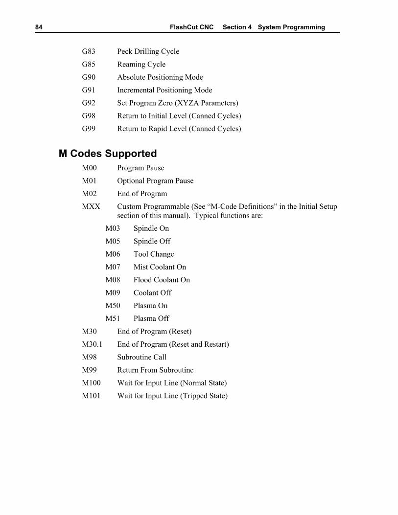
FlashCut CNC Section 4 System Programming 84
G83 Peck Drilling Cycle
G85 Reaming Cycle
G90 Absolute Positioning Mode
G91 Incremental Positioning Mode
G92 Set Program Zero (XYZA Parameters)
G98 Return to Initial Level (Canned Cycles)
G99 Return to Rapid Level (Canned Cycles)
M Codes Supported M00 Program Pause
M01 Optional Program Pause
M02 End of Program
MXX Custom Programmable (See “M-Code Definitions” in the Initial Setup section of this manual). Typical functions are:
M03 Spindle On
M05 Spindle Off
M06 Tool Change
M07 Mist Coolant On
M08 Flood Coolant On
M09 Coolant Off
M50 Plasma On
M51 Plasma Off
M30 End of Program (Reset)
M30.1 End of Program (Reset and Restart)
M98 Subroutine Call
M99 Return From Subroutine
M100 Wait for Input Line (Normal State)
M101 Wait for Input Line (Tripped State)

FlashCut CNC Section 4 System Programming 85
Other Commands Supported F Set Feedrate
T Select Tool
S Set Spindle Speed
( ) Comment
/ Optional Line
Advanced Keyword Commands and Functions EnableFO Enable Feedrate Override
DisableFO Disable Feedrate Override
SaveState Save Current Modal States
RestoreState Restore Saved Modal States
GetRackIndex Get Tool Rack Index
Key Programming Concepts There are two basic programming concepts you should understand before learning the G and M codes: Mode and Absolute vs. Incremental.
Mode Most G-code commands supported by FlashCut are modal, meaning they put the system into a particular mode of operation and don’t need to be repeated on every program line. A modal command stays in effect until another command changes the mode. Related modal commands that affect one aspect of program execution are called a mode group.
The following list shows the mode groups supported by FlashCut.
Movement G00 Rapid Tool Positioning
G01 Linear Interpolated Feedrate Move
G02 Clockwise Circular Feedrate Move
G03 Counter Clockwise Circular Feedrate Move
Circular Interpolation G17 XY Plane Selection
G18 XZ Plane Selection
G19 YZ Plane Selection
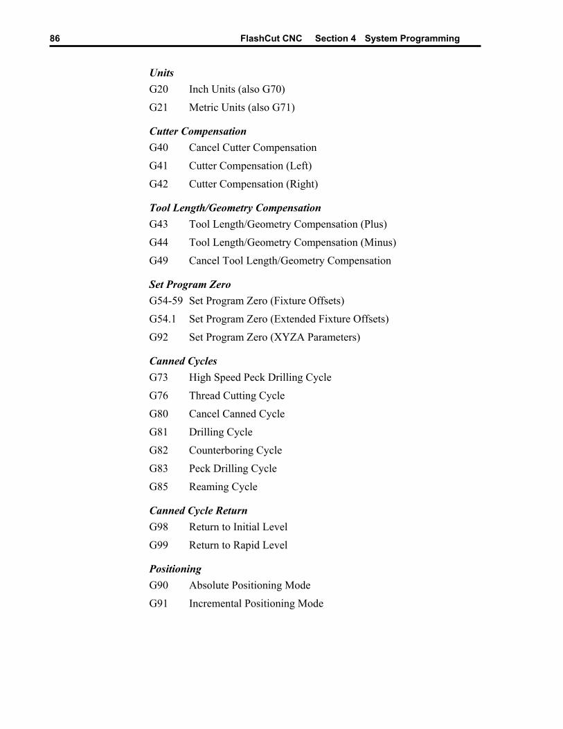
FlashCut CNC Section 4 System Programming 86
Units G20 Inch Units (also G70)
G21 Metric Units (also G71)
Cutter Compensation G40 Cancel Cutter Compensation
G41 Cutter Compensation (Left)
G42 Cutter Compensation (Right)
Tool Length/Geometry Compensation G43 Tool Length/Geometry Compensation (Plus)
G44 Tool Length/Geometry Compensation (Minus)
G49 Cancel Tool Length/Geometry Compensation
Set Program Zero G54-59 Set Program Zero (Fixture Offsets)
G54.1 Set Program Zero (Extended Fixture Offsets)
G92 Set Program Zero (XYZA Parameters)
Canned Cycles G73 High Speed Peck Drilling Cycle
G76 Thread Cutting Cycle
G80 Cancel Canned Cycle
G81 Drilling Cycle
G82 Counterboring Cycle
G83 Peck Drilling Cycle
G85 Reaming Cycle
Canned Cycle Return G98 Return to Initial Level
G99 Return to Rapid Level
Positioning G90 Absolute Positioning Mode
G91 Incremental Positioning Mode

FlashCut CNC Section 4 System Programming 87
Independent Modal Commands G52 Use Local Coordinate System
F Set Feedrate
S Set Spindle Speed
Absolute vs. Incremental All moves are either absolute or incremental. In an absolute move, the ending point is defined relative to Program Zero. In an incremental move, the ending point is defined relative to the current tool location. The G90/G91 commands tell the system which of these two modes to use (described below).
While there will be cases where incremental programming is useful, generally you should define your moves as absolute since it is a less error prone method of programming. All of the examples in the following section use absolute positioning unless otherwise noted.
G and M Code Reference
G00 Rapid Tool Positioning The G00 command moves the tool to the designated coordinate at the rapid rate using 3-axis linear interpolation. The rapid rate is calculated from the Maximum Feedrates defined in the Feedrate/Ramping panel of the Configuration dialog box.
Example:
G00 X1.0 Y2.0 Z1.5 Moves the tool to program coordinates X=1.0, Y=2.0, Z=1.5 at the rapid rate
When using G00, there are several things to keep in mind:
• You do not need to specify three coordinates, only the ones for which you want movement.
Example:
G00 X4.0 Y3.0 Moves the tool to program coordinates X=4.0, Y=3.0, leaving the Z position unchanged
• This is a modal command, meaning that all successive moves will be treated as rapid moves until another modal move command (G01, G02 or G03) occurs.
Example:
G00 X1.0 Y2.0 Z1.5 Rapid Move
X4.0 Y6.5 Z1.0 Rapid Move
G01 X3.0 Y3.0 Z1.4 Feedrate Move
X2.8 Y1.4 Z0 Feedrate Move
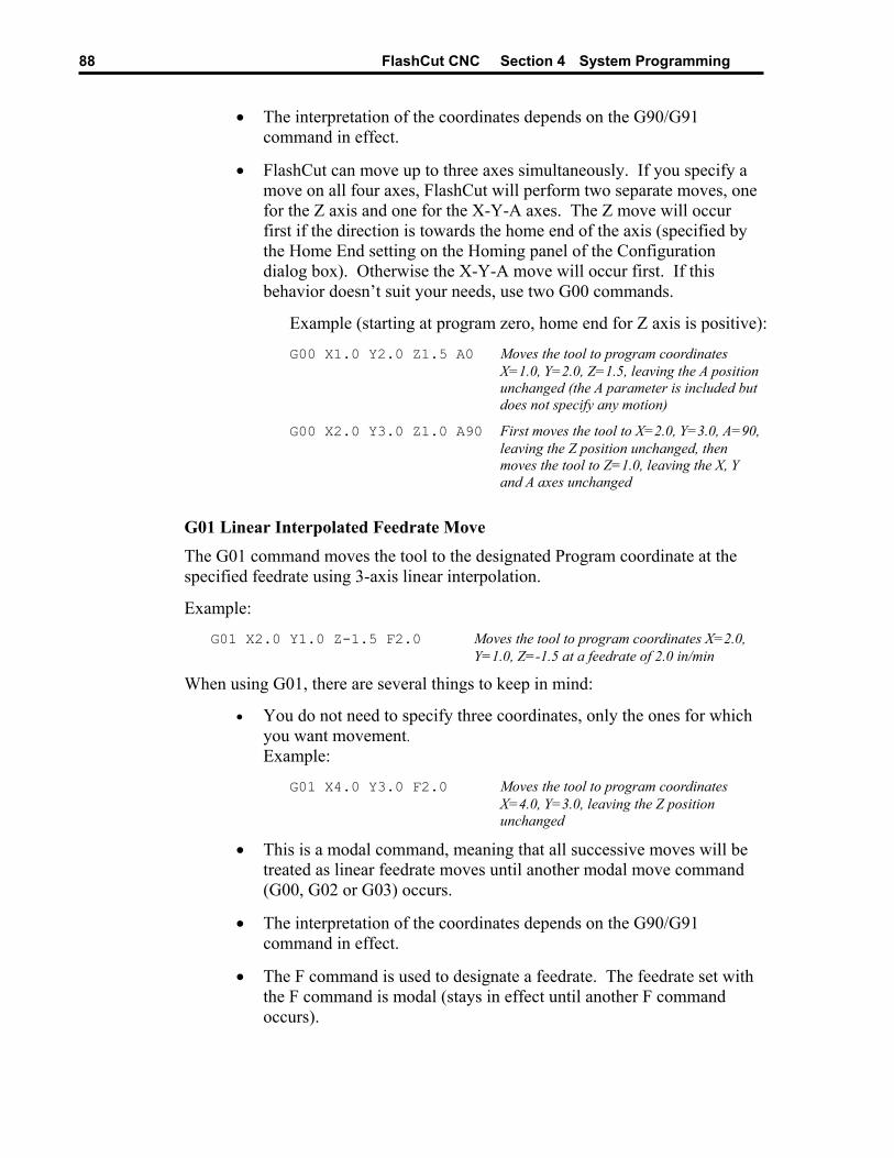
FlashCut CNC Section 4 System Programming 88
• The interpretation of the coordinates depends on the G90/G91 command in effect.
• FlashCut can move up to three axes simultaneously. If you specify a move on all four axes, FlashCut will perform two separate moves, one for the Z axis and one for the X-Y-A axes. The Z move will occur first if the direction is towards the home end of the axis (specified by the Home End setting on the Homing panel of the Configuration dialog box). Otherwise the X-Y-A move will occur first. If this behavior doesn’t suit your needs, use two G00 commands.
Example (starting at program zero, home end for Z axis is positive):
G00 X1.0 Y2.0 Z1.5 A0 Moves the tool to program coordinates X=1.0, Y=2.0, Z=1.5, leaving the A position unchanged (the A parameter is included but does not specify any motion)
G00 X2.0 Y3.0 Z1.0 A90 First moves the tool to X=2.0, Y=3.0, A=90, leaving the Z position unchanged, then moves the tool to Z=1.0, leaving the X, Y and A axes unchanged
G01 Linear Interpolated Feedrate Move The G01 command moves the tool to the designated Program coordinate at the specified feedrate using 3-axis linear interpolation.
Example:
G01 X2.0 Y1.0 Z-1.5 F2.0 Moves the tool to program coordinates X=2.0, Y=1.0, Z=-1.5 at a feedrate of 2.0 in/min
When using G01, there are several things to keep in mind:
• You do not need to specify three coordinates, only the ones for which you want movement. Example:
G01 X4.0 Y3.0 F2.0 Moves the tool to program coordinates X=4.0, Y=3.0, leaving the Z position unchanged
• This is a modal command, meaning that all successive moves will be treated as linear feedrate moves until another modal move command (G00, G02 or G03) occurs.
• The interpretation of the coordinates depends on the G90/G91 command in effect.
• The F command is used to designate a feedrate. The feedrate set with the F command is modal (stays in effect until another F command occurs).
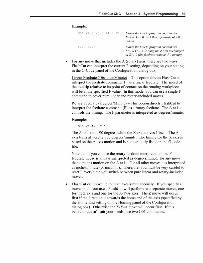
FlashCut CNC Section 4 System Programming 89
Example:
G01 X4.0 Y3.0 Z1.0 F7.0 Moves the tool to program coordinates X=4.0, Y=3.0, Z=1.0 at a feedrate of 7.0 in/min
X2.0 Y2.5 Moves the tool to program coordinates X=2.0 Y=2.5, leaving the Z axis unchanged at Z=1.0 (the feedrate remains 7.0 in/min)
• For any move that includes the A (rotary) axis, there are two ways FlashCut can interpret the current F setting, depending on your setting in the G-Code panel of the Configuration dialog box.
Linear Feedrate (Distance/Minute) – This option directs FlashCut to interpret the feedrate command (F) as a linear feedrate. The speed of the tool tip relative to its point of contact on the rotating workpiece will be at the specified F value. In this mode, you can use a single F command to cover pure linear and rotary-included moves.
Rotary Feedrate (Degrees/Minute) – This option directs FlashCut to interpret the feedrate command (F) as a rotary feedrate. The A axis controls the timing. The F parameter is interpreted as degrees/minute.
Example: G01 X1 A90 F360
The A axis turns 90 degrees while the X axis moves 1 inch. The A axis turns at exactly 360 degrees/minute. The timing for the X axis is based on the A axis motion and is not explicitly listed in the G-code file.
Note that if you choose the rotary feedrate interpretation, the F feedrate in use is always interpreted as degrees/minute for any move that contains motion on the A axis. For all other moves, it's interpreted as inches/minute (or mm/min). Therefore, you must be very careful to reset F every time you switch between pure linear and rotary-included moves.
• FlashCut can move up to three axes simultaneously. If you specify a move on all four axes, FlashCut will perform two separate moves, one for the Z axis and one for the X-Y-A axes. The Z move will occur first if the direction is towards the home end of the axis (specified by the Home End setting on the Homing panel of the Configuration dialog box). Otherwise the X-Y-A move will occur first. If this behavior doesn’t suit your needs, use two G01 commands.
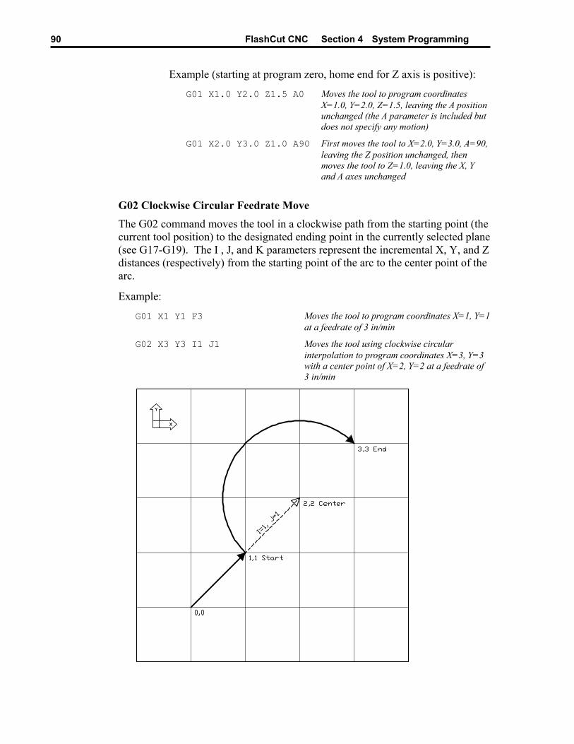
FlashCut CNC Section 4 System Programming 90
Example (starting at program zero, home end for Z axis is positive):
G01 X1.0 Y2.0 Z1.5 A0 Moves the tool to program coordinates X=1.0, Y=2.0, Z=1.5, leaving the A position unchanged (the A parameter is included but does not specify any motion)
G01 X2.0 Y3.0 Z1.0 A90 First moves the tool to X=2.0, Y=3.0, A=90, leaving the Z position unchanged, then moves the tool to Z=1.0, leaving the X, Y and A axes unchanged
G02 Clockwise Circular Feedrate Move The G02 command moves the tool in a clockwise path from the starting point (the current tool position) to the designated ending point in the currently selected plane (see G17-G19). The I , J, and K parameters represent the incremental X, Y, and Z distances (respectively) from the starting point of the arc to the center point of the arc.
Example:
G01 X1 Y1 F3 Moves the tool to program coordinates X=1, Y=1 at a feedrate of 3 in/min
G02 X3 Y3 I1 J1 Moves the tool using clockwise circular interpolation to program coordinates X=3, Y=3 with a center point of X=2, Y=2 at a feedrate of 3 in/min
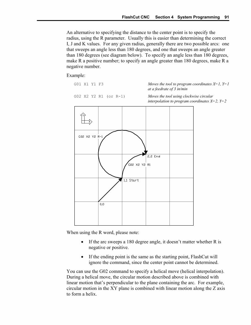
FlashCut CNC Section 4 System Programming 91
An alternative to specifying the distance to the center point is to specify the radius, using the R parameter. Usually this is easier than determining the correct I, J and K values. For any given radius, generally there are two possible arcs: one that sweeps an angle less than 180 degrees, and one that sweeps an angle greater than 180 degrees (see diagram below). To specify an angle less than 180 degrees, make R a positive number; to specify an angle greater than 180 degrees, make R a negative number.
Example:
G01 X1 Y1 F3 Moves the tool to program coordinates X=1, Y=1 at a feedrate of 3 in/min
G02 X2 Y2 R1 (or R-1) Moves the tool using clockwise circular interpolation to program coordinates X=2, Y=2
When using the R word, please note:
• If the arc sweeps a 180 degree angle, it doesn’t matter whether R is negative or positive.
• If the ending point is the same as the starting point, FlashCut will ignore the command, since the center point cannot be determined.
You can use the G02 command to specify a helical move (helical interpolation). During a helical move, the circular motion described above is combined with linear motion that’s perpendicular to the plane containing the arc. For example, circular motion in the XY plane is combined with linear motion along the Z axis to form a helix.
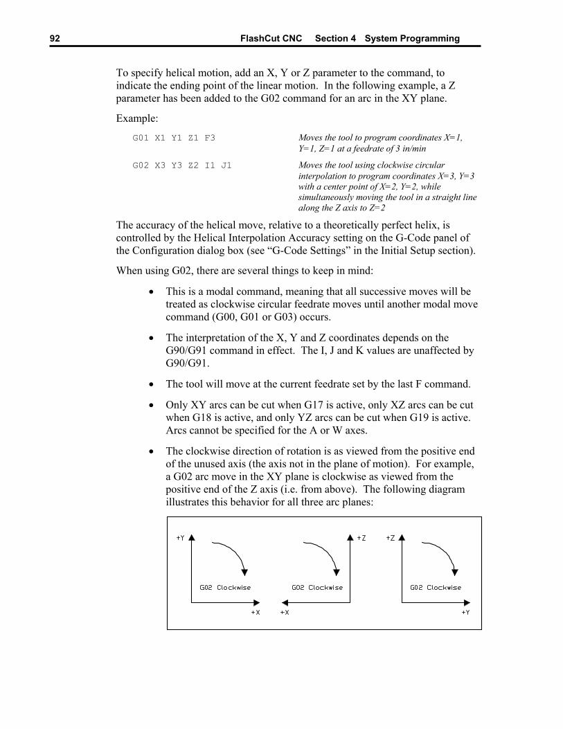
FlashCut CNC Section 4 System Programming 92
To specify helical motion, add an X, Y or Z parameter to the command, to indicate the ending point of the linear motion. In the following example, a Z parameter has been added to the G02 command for an arc in the XY plane.
Example:
G01 X1 Y1 Z1 F3 Moves the tool to program coordinates X=1, Y=1, Z=1 at a feedrate of 3 in/min
G02 X3 Y3 Z2 I1 J1 Moves the tool using clockwise circular interpolation to program coordinates X=3, Y=3 with a center point of X=2, Y=2, while simultaneously moving the tool in a straight line along the Z axis to Z=2
The accuracy of the helical move, relative to a theoretically perfect helix, is controlled by the Helical Interpolation Accuracy setting on the G-Code panel of the Configuration dialog box (see “G-Code Settings” in the Initial Setup section).
When using G02, there are several things to keep in mind:
• This is a modal command, meaning that all successive moves will be treated as clockwise circular feedrate moves until another modal move command (G00, G01 or G03) occurs.
• The interpretation of the X, Y and Z coordinates depends on the G90/G91 command in effect. The I, J and K values are unaffected by G90/G91.
• The tool will move at the current feedrate set by the last F command.
• Only XY arcs can be cut when G17 is active, only XZ arcs can be cut when G18 is active, and only YZ arcs can be cut when G19 is active. Arcs cannot be specified for the A or W axes.
• The clockwise direction of rotation is as viewed from the positive end of the unused axis (the axis not in the plane of motion). For example, a G02 arc move in the XY plane is clockwise as viewed from the positive end of the Z axis (i.e. from above). The following diagram illustrates this behavior for all three arc planes:
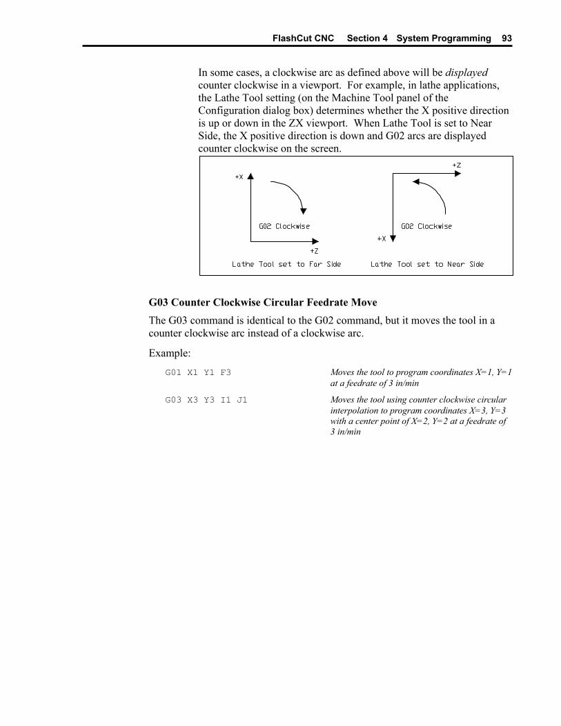
FlashCut CNC Section 4 System Programming 93
In some cases, a clockwise arc as defined above will be displayed counter clockwise in a viewport. For example, in lathe applications, the Lathe Tool setting (on the Machine Tool panel of the Configuration dialog box) determines whether the X positive direction is up or down in the ZX viewport. When Lathe Tool is set to Near Side, the X positive direction is down and G02 arcs are displayed counter clockwise on the screen.
G03 Counter Clockwise Circular Feedrate Move The G03 command is identical to the G02 command, but it moves the tool in a counter clockwise arc instead of a clockwise arc.
Example:
G01 X1 Y1 F3 Moves the tool to program coordinates X=1, Y=1 at a feedrate of 3 in/min
G03 X3 Y3 I1 J1 Moves the tool using counter clockwise circular interpolation to program coordinates X=3, Y=3 with a center point of X=2, Y=2 at a feedrate of 3 in/min
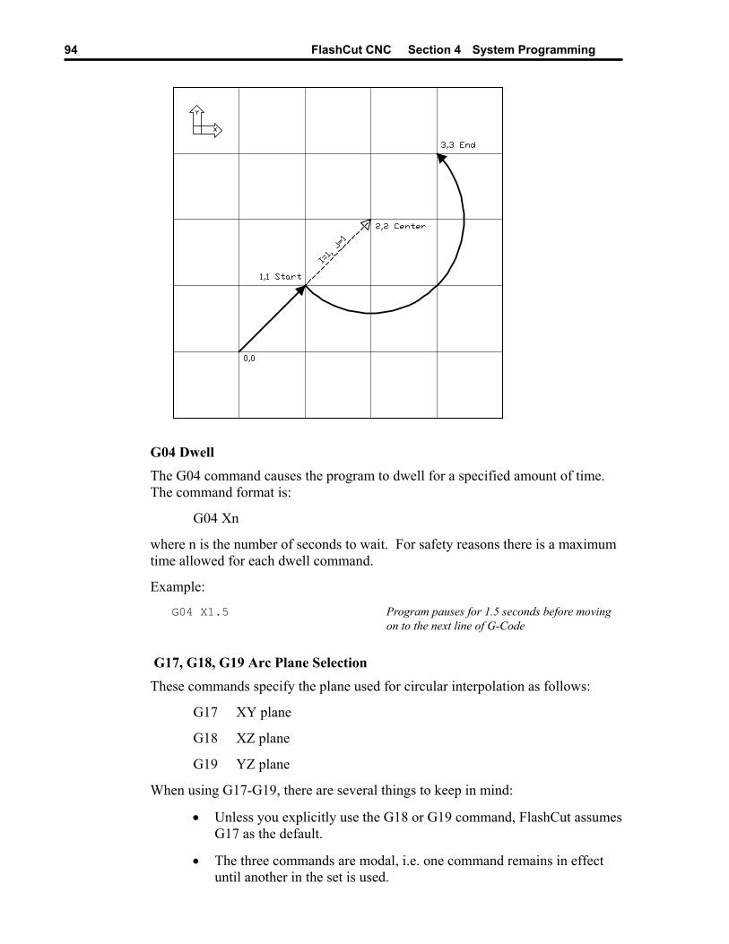
FlashCut CNC Section 4 System Programming 94
G04 Dwell The G04 command causes the program to dwell for a specified amount of time. The command format is:
G04 Xn
where n is the number of seconds to wait. For safety reasons there is a maximum time allowed for each dwell command.
Example:
G04 X1.5 Program pauses for 1.5 seconds before moving on to the next line of G-Code
G17, G18, G19 Arc Plane Selection
These commands specify the plane used for circular interpolation as follows:
G17 XY plane
G18 XZ plane
G19 YZ plane
When using G17-G19, there are several things to keep in mind:
• Unless you explicitly use the G18 or G19 command, FlashCut assumes G17 as the default.
• The three commands are modal, i.e. one command remains in effect until another in the set is used.
FlashCut CNC Section 4 System Programming 95
G20, G21 Inch Units and Metric Units
The G20 command indicates that all G-Code commands are in inch units. FlashCut then assumes all distances are in inches and all feedrates are in inches/minute. For compatibility reasons, FlashCut accepts G70 as equivalent to G20.
The G21 command indicates that all G-Code commands are in metric units. FlashCut then assumes all distances are in millimeters and all feedrates are in millimeters/minute. For compatibility reasons, FlashCut accepts G71 as equivalent to G21.
You will only need these commands when the units used in the G-Code file don’t match the System Units setting on the System Options panel of the Configuration dialog box. If you don’t use either command, FlashCut assumes all program values are consistent with the configuration setting.
G27 Home to Switches
The G27 command homes the machine tool to its home switches, in a similar manner as the Seek Home button on the Home Control Panel. The purpose of this command is to allow checking for positioning errors, and to allow re-zeroing to the switches. This is especially useful when running large G-Code files. The command lets you home the machine at any point in the file, and optionally have FlashCut display the homing discrepancy dialog if the positioning error is not within the desired tolerance (which pauses execution of the file).
Note that Machine Zero must be set before you run a G-Code file that uses this command.
For more details, see “Home Control Panel” in the Main Screen Features section, and “Homing Settings” in the Initial Setup section.
G28, G30 Move to Reference Point The G28 and G30 commands move the tool at the rapid rate to the associated reference point defined in the Reference Points panel of the Configuration dialog box. These positions are defined either in machine or program coordinates. When a position is defined in machine coordinates, Machine Zero must be set for this command to be used. Note that G28 typically is used for moving to the tool change position and/or Machine Zero (reference point 1).
The sequence of axis motions follows a general-purpose scheme that’s described under “Point Control Panel” in the Main Screen Features section of this manual.
If you want the G28/G30 command to move only some of the axes on your machine tool, you can limit the movement to those axes by adding the parameters “X0”, “Y0”, “Z0” or “A0” after the command. Then, FlashCut moves only the indicated axes to the reference point coordinates. A typical use is to raise only the Z axis for a manual tool change (“G28 Z0”).
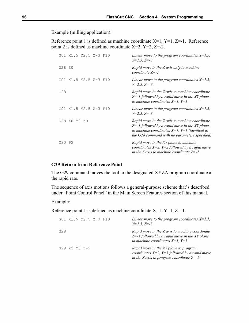
FlashCut CNC Section 4 System Programming 96
Example (milling application):
Reference point 1 is defined as machine coordinate X=1, Y=1, Z=-1. Reference point 2 is defined as machine coordinate X=2, Y=2, Z=-2.
G01 X1.5 Y2.5 Z-3 F10 Linear move to the program coordinates X=1.5, Y=2.5, Z=-3
G28 Z0 Rapid move in the Z axis only to machine coordinate Z=-1
G01 X1.5 Y2.5 Z-3 F10 Linear move to the program coordinates X=1.5, Y=2.5, Z=-3
G28 Rapid move in the Z axis to machine coordinate Z=-1 followed by a rapid move in the XY plane to machine coordinates X=1, Y=1
G01 X1.5 Y2.5 Z-3 F10 Linear move to the program coordinates X=1.5, Y=2.5, Z=-3
G28 X0 Y0 Z0 Rapid move in the Z axis to machine coordinate Z=-1 followed by a rapid move in the XY plane to machine coordinates X=1, Y=1 (identical to the G28 command with no parameters specified)
G30 P2 Rapid move in the XY plane to machine coordinates X=2, Y=2 followed by a rapid move in the Z axis to machine coordinate Z=-2
G29 Return from Reference Point The G29 command moves the tool to the designated XYZA program coordinate at the rapid rate.
The sequence of axis motions follows a general-purpose scheme that’s described under “Point Control Panel” in the Main Screen Features section of this manual.
Example:
Reference point 1 is defined as machine coordinate X=1, Y=1, Z=-1.
G01 X1.5 Y2.5 Z-3 F10 Linear move to the program coordinates X=1.5, Y=2.5, Z=-3
G28 Rapid move in the Z axis to machine coordinate Z=-1 followed by a rapid move in the XY plane to machine coordinates X=1, Y=1
G29 X2 Y3 Z-2 Rapid move in the XY plane to program coordinates X=2, Y=3 followed by a rapid move in the Z axis to program coordinate Z=-2
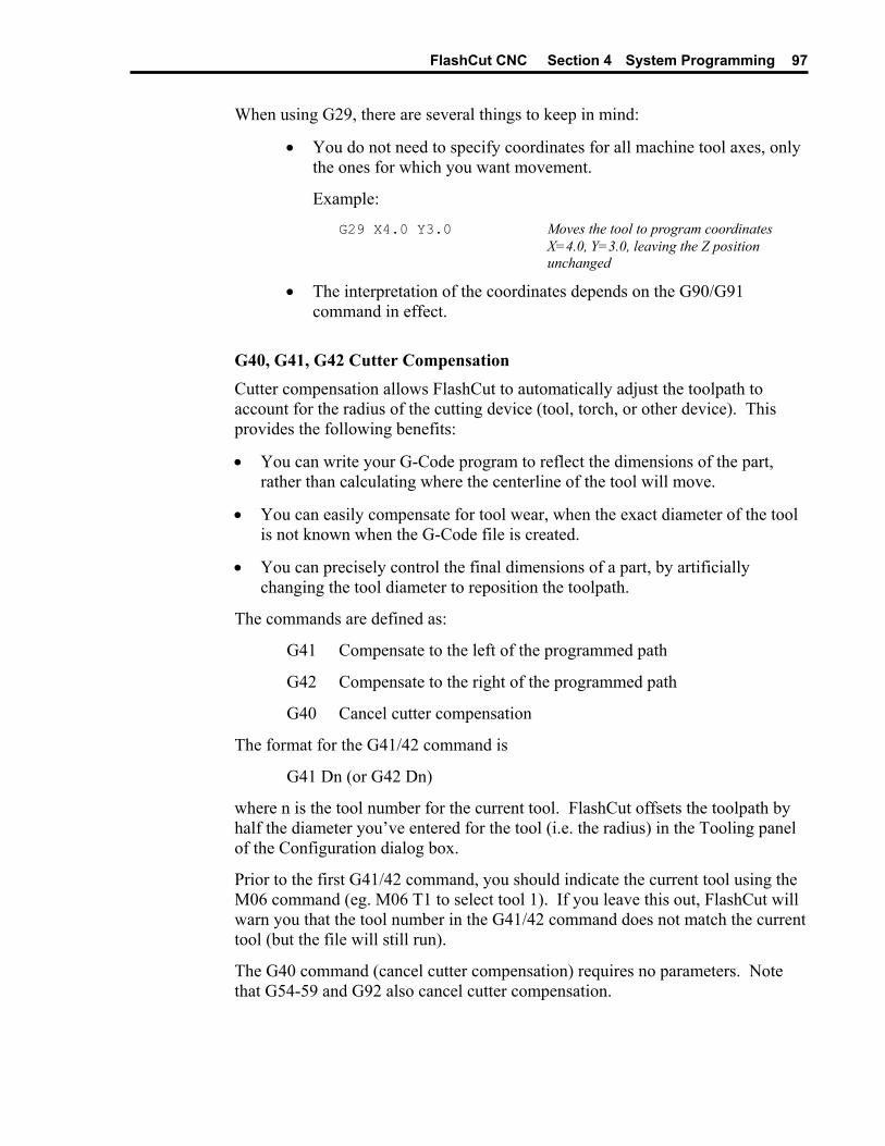
FlashCut CNC Section 4 System Programming 97
When using G29, there are several things to keep in mind:
• You do not need to specify coordinates for all machine tool axes, only the ones for which you want movement.
Example:
G29 X4.0 Y3.0 Moves the tool to program coordinates X=4.0, Y=3.0, leaving the Z position unchanged
• The interpretation of the coordinates depends on the G90/G91 command in effect.
G40, G41, G42 Cutter Compensation Cutter compensation allows FlashCut to automatically adjust the toolpath to account for the radius of the cutting device (tool, torch, or other device). This provides the following benefits:
• You can write your G-Code program to reflect the dimensions of the part, rather than calculating where the centerline of the tool will move.
• You can easily compensate for tool wear, when the exact diameter of the tool is not known when the G-Code file is created.
• You can precisely control the final dimensions of a part, by artificially changing the tool diameter to reposition the toolpath.
The commands are defined as:
G41 Compensate to the left of the programmed path
G42 Compensate to the right of the programmed path
G40 Cancel cutter compensation
The format for the G41/42 command is
G41 Dn (or G42 Dn)
where n is the tool number for the current tool. FlashCut offsets the toolpath by half the diameter you’ve entered for the tool (i.e. the radius) in the Tooling panel of the Configuration dialog box.
Prior to the first G41/42 command, you should indicate the current tool using the M06 command (eg. M06 T1 to select tool 1). If you leave this out, FlashCut will warn you that the tool number in the G41/42 command does not match the current tool (but the file will still run).
The G40 command (cancel cutter compensation) requires no parameters. Note that G54-59 and G92 also cancel cutter compensation.

FlashCut CNC Section 4 System Programming 98
You’ll activate cutter compensation just before cutting a feature (profile, pocket, etc.) then cancel cutter compensation immediately upon completing the feature. The typical sequence of commands is –
1. Select tool with M06 command (eg. M06 T1)
2. Move Z axis up to safe height above workpiece
3. Activate cutter compensation using G41 or G42
4. Move X and Y axes together (G00 or G01) to a point on the feature (called the ‘approach’ move)
5. Move Z axis down into the workpiece
6. Do any number of XY moves (lines and arcs) to cut the feature, all at the same Z axis depth
7. Move Z axis up to safe height above workpiece
8. Cancel cutter compensation using G40
9. Repeat steps 3-8 for all features
Be sure to follow these steps for each distinct feature of the part. Cutter compensation should be turned off whenever the machine is not actually cutting a feature (e.g. when returning to machine zero or the tool change position).
Note that cutter compensation is available only in milling mode (Machine Type drop-down menu on the Machine Tool panel of the Configuration dialog box).
For information on customizing cutter compensation, please see “Cutter Compensation Setup” in the Initial Setup section of this manual.
The following example demonstrates use of cutter compensation.
Example:
This G-Code file cuts on the inside of two 1-inch squares.
F10.00 Set feedrate
M06 T1 Select tool 1
G00 Z 0.25 Raise Z to safe height
G41 D1 Activate cutter comp left
G00 X 1.00 Y 1.00 Approach move
G01 Z-0.10 Plunge into workpiece
G01 X 2.00 Y 1.00 Cut first side of square
G01 X 2.00 Y 2.00
G01 X 1.00 Y 2.00
G01 X 1.00 Y 1.00 Cut last side of square
G00 Z 0.25 Raise Z to safe height

FlashCut CNC Section 4 System Programming 99
G40 Cancel cutter compensation
G41 D1 Activate cutter comp left
G00 X 3.00 Y 1.00 Approach move
G01 Z-0.10 Plunge into workpiece
G01 X 4.00 Y 1.00 Cut first side of square
G01 X 4.00 Y 2.00
G01 X 3.00 Y 2.00
G01 X 3.00 Y 1.00 Cut last side of square
G00 Z 0.25 Raise Z to safe height
G40 Turn off cutter compensation
G00 X 0.00 Y 0.00 Return to program zero
G52 Local Coordinate System The G52 command activates a local coordinate system that FlashCut uses in place of your original program coordinates for all absolute positioning moves. The X, Y, Z and A parameters indicate the offset from your Program Zero location to the origin for the local coordinate system.
For example, "G52 X1 Y2 Z-4" would activate a local coordinate system whose origin is at a distance of 1, 2, -4 from the original Program Zero.
All absolute moves are made relative to the new local coordinate system. To cancel use of the local coordinate system in the middle of a G-code file, use the command “G52 X0 Y0 Z0 A0” (using only the letters for axes used on your machine).
When FlashCut reads a G52 command, it displays a magenta dot in the Toolpath Viewport Box showing the origin of the local coordinate system.
Note that the local coordinate system only applies to the G-code file being executed. The G52 command has no effect the Program Zero location. FlashCut automatically cancels the local coordinate system when it completes execution of a G-code file.
If you reposition Program Zero using the G54-59 or G92 commands, the G52 command remains in effect, with local coordinate system now offset from the new Program Zero location.
Example:
G01 X1.0 Y3.0 Z-1.5 F12 Moves the tool to program coordinates X=1.0, Y=3.0, Z=-1.5
G52 X3 Y-7 Z0 Activates a local coordinate system with origin at X=3, Y=-7, Z=0 relative to Program Zero (the machine tool does not move)
G01 X1.0 Y10.0 Z2.0 Moves the tool to the point X=1.0, Y=10.0, Z=2.0 relative to the local coordinate system as defined by the G52 command above
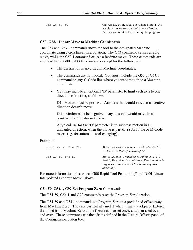
FlashCut CNC Section 4 System Programming 100
G52 X0 Y0 Z0 Cancels use of the local coordinate system. All absolute moves are again relative to Program Zero as you set it before running the program
G53, G53.1 Linear Move to Machine Coordinates The G53 and G53.1 commands move the tool to the designated Machine coordinate using 3-axis linear interpolation. The G53 command causes a rapid move, while the G53.1 command causes a feedrate move. These commands are identical to the G00 and G01 commands except for the following:
• The destination is specified in Machine coordinates.
• The commands are not modal. You must include the G53 or G53.1 command on any G-Code line where you want motion to a Machine coordinate.
• You may include an optional ‘D’ parameter to limit each axis to one direction of motion, as follows:
D1: Motion must be positive. Any axis that would move in a negative direction doesn’t move.
D-1: Motion must be negative. Any axis that would move in a positive direction doesn’t move.
A typical use for the ‘D’ parameter is to suppress motion in an unwanted direction, when the move is part of a subroutine or M-Code macro (eg. for automatic tool changing).
Example:
G53.1 X2 Y3 Z-4 F12 Moves the tool to machine coordinates X=2.0, Y=3.0, Z=-4.0 at a feedrate of 12
G53 X3 Y4 Z-5 D1 Moves the tool to machine coordinates X=3.0, Y=4.0, Z=-4.0 at the rapid rate (Z axis motion is suppressed since it would be in the negative direction)
For more information, please see “G00 Rapid Tool Positioning” and “G01 Linear Interpolated Feedrate Move” above.
G54-59, G54.1, G92 Set Program Zero Commands The G54-59, G54.1 and G92 commands reset the Program Zero location.
The G54-59 and G54.1 commands set Program Zero to a predefined offset away from Machine Zero. They are particularly useful when using a workpiece fixture; the offset from Machine Zero to the fixture can be set once, and then used over and over. These commands use the offsets defined in the Fixture Offsets panel of the Configuration dialog box.
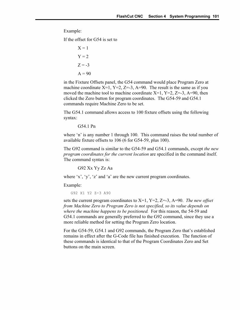
FlashCut CNC Section 4 System Programming 101
Example:
If the offset for G54 is set to
X = 1
Y = 2
Z = -3
A = 90
in the Fixture Offsets panel, the G54 command would place Program Zero at machine coordinate X=1, Y=2, Z=-3, A=90. The result is the same as if you moved the machine tool to machine coordinate X=1, Y=2, Z=-3, A=90, then clicked the Zero button for program coordinates. The G54-59 and G54.1 commands require Machine Zero to be set.
The G54.1 command allows access to 100 fixture offsets using the following syntax:
G54.1 Pn
where ‘n’ is any number 1 through 100. This command raises the total number of available fixture offsets to 106 (6 for G54-59, plus 100).
The G92 command is similar to the G54-59 and G54.1 commands, except the new program coordinates for the current location are specified in the command itself. The command syntax is:
G92 Xx Yy Zz Aa
where ‘x’, ‘y’, ‘z’ and ‘a’ are the new current program coordinates.
Example: G92 X1 Y2 Z-3 A90
sets the current program coordinates to X=1, Y=2, Z=-3, A=90. The new offset from Machine Zero to Program Zero is not specified, so its value depends on where the machine happens to be positioned. For this reason, the 54-59 and G54.1 commands are generally preferred to the G92 command, since they use a more reliable method for setting the Program Zero location.
For the G54-59, G54.1 and G92 commands, the Program Zero that’s established remains in effect after the G-Code file has finished execution. The function of these commands is identical to that of the Program Coordinates Zero and Set buttons on the main screen.
FlashCut CNC Section 4 System Programming 102
M06 Tool Change and T Select Tool Commands
To indicate tool changes in the G-Code file, use the M06 and T commands as follows:
M06 Tn
where n is the tool number in the Tooling panel of the Configuration dialog box.
Example: M06 T3
The T command can be used on any line prior to the M06 command; it does not need to be on the same line as M06.
FlashCut handles the M06 command according to the settings on the Tool Change panel of the Configuration dialog box. See “Tool Change” in the Initial Setup section for details.
The M06 command does not move the machine tool to the tool change position. This is done using the G28 command described above. If you’re changing tools manually, it’s good practice to place the G28 command (and the M05 spindle off command) on the lines directly preceding the M06 command.
G43, G44, G49 Tool Length/Geometry Compensation Commands Tool length/geometry compensation lets FlashCut account for differences in tool lengths and geometry when the G-Code file is executed. This lets you create a G-Code program without knowing the exact geometry of the tools that will be used to cut the part.
In milling mode, compensation is generally used to account for differences in tool lengths in the Z direction. Generally, X and Y offsets are not used. However, to accommodate a milling-style machine with multiple spindles, the offset between spindles can be handled using the X and Y components of the tool offset.
In lathe mode, compensation is generally used to account for differences in tool tip positions, in both X and Z directions.
THESE COMMANDS ARE NOT FOR THE NOVICE CNC USER. WHEN NOT PROPERLY USED, TOOL LENGTH AND GEOMETRY COMPENSATION CAN CRASH THE MACHINE TOOL, CAUSING SERIOUS DAMAGE TO YOUR WORKPIECE OR MACHINE TOOL.
FlashCut CNC Section 4 System Programming 103
When applying tool length and geometry compensation, FlashCut uses the offsets defined in the Tooling panel of the Configuration dialog box. See “Tooling Settings” in the Initial Setup section for more information on defining your tool offsets.
For tool length and geometry compensation to work properly, FlashCut must know what tool is in use at all times. Therefore, you must indicate every tool change with an M06 command in the G-Code file. Similarly, whenever you change a tool between running G-Code files, you should select it in the Current Tool pull-down menu. The Compensation Mode pull-down menu is set to Positive (G43) by default.
Technically, the M06 command indicating your starting tool is optional, but we recommend you include it so the file is self-contained and less prone to operator error. However, if you choose not to include an M06 command for your starting tool, you must make certain you choose your starting tool from the Current Tool pull-down menu on the main screen, before running the file.
Once the M06 command has set the current tool, the G43 command applies the proper offset to account for the current tool’s length or geometry as follows:
G43 Hn
where n is the tool number for the current tool.
Milling Mode (Tool Length Compensation) – The G43 command tells FlashCut to shift all subsequent Z axis moves away from the workpiece (in the positive Z direction) by an amount equal to the Z offset for tool ‘n’.
Lathe Mode (Tool Geometry Compensation) – The G43 command tells FlashCut to shift all subsequent moves away from the workpiece (in the positive X and Z directions) by an amount equal to the X and Z offset for tool ‘n’.
If tool length/geometry compensation is already in effect for a previous tool, the resulting shift away from the workpiece equals the difference between offsets for tool ‘n’ and the previous tool.
Milling Mode Example:
G43 H3 Shifts all subsequent Z axis moves away from the workpiece (in the positive Z direction) by the Z offset for Tool #3
Lathe Mode Example:
G43 H3 Shifts all subsequent X and Z axis moves away from the workpiece (in the positive X and Z directions) by the X and Z offset for Tool #3
The G44 command is identical to the G43 command, except that it shifts all moves in the direction opposite from G43. Unless you are an experienced CNC programmer and know how to use G44 correctly, G43 is the preferred command.
The G49 command cancels tool length/geometry compensation.
FlashCut CNC Section 4 System Programming 104
When using tool length compensation there are several important things to keep in mind:
• You must predefine all tools and associated offsets in the Tooling panel of the Configuration dialog box.
• It’s good practice to include an M06 tool change and a G43 compensation command for the first tool used, near the beginning of the G-Code program.
• FlashCut does not cancel tool offset when it finishes processing a G-Code file. TO AVOID CRASHES, IT IS VERY IMPORTANT THAT YOU UPDATE THE CURRENT TOOL DROP-DOWN MENU, WHENEVER YOU MANUALLY CHANGE A TOOL.
• The G43, G44 and G49 commands are modal, so the current tool offset remains active until FlashCut executes another one of these three commands, or you set the Compensation Mode pull-down menu.
• It’s good practice to use the G43 command in the line directly following the M06 command.
The following example illustrates proper use of the tool change and tool length compensation commands.
Milling Mode Example:
There are two basic methods for setting Program Zero, and both will be covered in this example.
• Use G54-G59 to apply a fixture offset (“Fixture Offset Method”). This method requires Machine Zero and the correct fixture offset to be set.
• Touch the tip of the tool to the top of the workpiece and click the Program Coordinates Zero button on the main screen (“Tool Touch-Off Method”). This method doesn’t require Machine Zero or a fixture offset to be set.
In this example, the tool change position (reference point 1 on the Reference Points panel of the Configuration dialog box) is defined as machine coordinates X=0, Y=0, Z=0 (Machine Zero). Tool #1 is loaded in the machine tool, and selected in the Current Tool pull-down menu on the main screen. The Compensation Mode pull-down menu is set to Positive (G43). Machine Zero has been set. The machine tool is at Machine Zero. The tooling configuration is shown below.

FlashCut CNC Section 4 System Programming 105
Program Zero is set as follows:
Tool Touch-Off Method:
Program zero is set at machine coordinate X=1, Y=1, Z =-4, with the tip of Tool #1 touching the top surface of the workpiece.
Fixture Offset Method:
Program zero is temporarily set at Machine Zero. The fixture offset for G54 is set to X=1, Y=1, Z=-5.5, A=0 in the Fixture Offsets panel of the Configuration dialog box. The fixture offset is the machine coordinate when the spindle nose touches the top surface of the workpiece. When the G54 command in the G-Code file is executed, Program Zero will be set at its associated offset value.
The G-Code file is as follows:
G54 Sets Program Zero (Fixture Offset Method Only). Program coordinates change to X=-1, Y=-1, Z=4
G28 The machine is already at the tool change position so nothing happens
M05 Turns off the spindle
M06 T1 Changes the tool to Tool #1, which is already loaded
G43 H1 Applies tool length compensation for Tool #1. Since Tool #1 was already loaded, and Compensation Mode was set to Positive (G43) when the program started, this command doesn’t do anything. Program coordinates and machine coordinates remain unchanged
M03 Turns on the spindle
G29 X0 Y0 Z.25 Moves the X and Y axes across, then the Z axis down to program coordinates X=0, Y=0, Z=0.25, machine coordinates X=1, Y=1, Z=-3.75
FlashCut CNC Section 4 System Programming 106
G01 Z-1.0 F10 Moves the Z axis down to program coordinates X=0, Y=0, Z=-1, machine coordinates X=1, Y=1, Z=-5
G01 X3 Y3 Z-1 F20 Linear interpolation to program coordinates X=3, Y=3, Z=-1, machine coordinates X=4, Y=4, Z=-5
G28 Moves the Z axis up, then the X and Y axes across to the tool change position, program coordinates X=-1, Y=-1, Z=4, machine coordinates X=0, Y=0, Z=0
M05 Turns off the spindle
M06 T2 Changes the tool to Tool #2
G43 H2 Applies tool length compensation for Tool #2. The Z program coordinate shifts by -0.750 (1.500 – 2.250). The program coordinates are now X=-1, Y=-1, Z=3.25. The machine coordinates remain unchanged at X=0, Y=0, Z=0
M03 Turns on the spindle
G29 X0 Y0 Z0.25 Moves the X and Y axes across, then the Z axis down to program coordinates X=0, Y=0, Z=0.25, machine coordinates X=1, Y=1, Z=-3.0
G01 Z-1.0 F10 Moves the Z axis down to program coordinates X=0, Y=0, Z=-1, machine coordinates X=1, Y=1, Z=-4.25
G01 X3 Y3 Z-1 F20 Linear interpolation to program coordinates X=3, Y=3, Z=-1, machine coordinates X=4, Y=4, Z=-4.25
G28 Moves the Z axis up, then the X and Y axes across to the tool change position, program coordinates X=-1, Y=-1, Z=3.25, machine coordinates X=0, Y=0, Z=0
M05 Turns off the spindle
G73, G80, G81, G82, G83, G85, G98, G99 Drilling Canned Cycle Commands Canned drilling cycles simplify programming by letting you specify standard drilling operations with a single command. FlashCut supports the following drilling cycles:
G73 High Speed Peck Drilling Cycle
G80 Cancel Canned Cycle
G81 Drilling Cycle
G82 Counterboring Cycle
G83 Peck Drilling Cycle
G85 Reaming Cycle

FlashCut CNC Section 4 System Programming 107
The following diagrams illustrate the sequence of moves for all drilling cycles. The rest of this section refers to these diagrams.
(G98)R Level
Top of Workpiece
Z Level
Initial Point Hole Start Point
(G99)
Initial Level
G81 Drilling Cycle / G82 Counterboring Cycle
FeedrateMove
RapidMove
Key
Dwell (G82 only)
(G98)R Level
Top of Workpiece
Z Level
Initial Point Hole Start Point
(G99)
Initial Level
G85 Reaming Cycle
FeedrateMove
RapidMove
Key
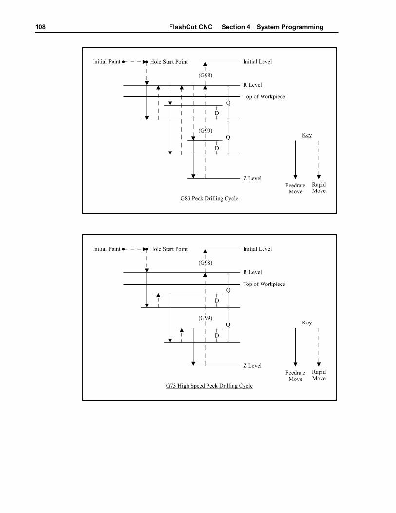
FlashCut CNC Section 4 System Programming 108
Q
(G98)R Level
Top of Workpiece
Z Level
Initial Point Hole Start Point
Q
D
(G99)
D
Initial Level
G83 Peck Drilling Cycle
FeedrateMove
RapidMove
Key
Q
(G98)R Level
Top of Workpiece
Z Level
Initial Point Hole Start Point
Q
D
(G99)
D
Initial Level
G73 High Speed Peck Drilling Cycle
FeedrateMove
RapidMove
Key

FlashCut CNC Section 4 System Programming 109
The general command syntax for drilling cycles is as follows:
Gn Xx Yy Rr Zz Qq Pp Ff Ll
where the parameters are
n: Drilling cycle number (73, 81, 82, 83 or 85)
x: X coordinate of Hole Start Point (G90 mode) or distance for rapid move from Initial Point to Hole Start Point (G91 mode)
y: Y coordinate of Hole Start Point (G90 mode) or distance for rapid move from Initial Point to Hole Start Point (G91 mode)
r: Z coordinate of R Level (G90 mode) or distance for rapid move from Hole Start Point to R Level (G91 mode)
z: Z coordinate of Z Level (G90 mode) or distance from R Level to Z Level (G91 mode)
q: Depth of cut for each downward cutting move (G73/G83 only)
p: Dwell time at Z level, in milliseconds (G82 only)
f: Feedrate for each downward cutting move (and retract move for G85 only)
l: Number of times to repeat the canned cycle (G91 mode only)
The required parameters are R, Z, F (plus Q for G73/G83, and P for G82).
The G98 and G99 commands affect the final Z axis rapid move, upward out of the completed hole (rightmost move in each diagram), as follows:
G98: Z axis moves up to the Initial Level
G99: Z axis moves up to the R Level
G98 and G99 compose a mode group, with G98 being the default if neither is specified in the G-Code file. You can include either command on the same line as the drilling cycle command (before or after the drilling cycle command and all parameters).
The D distance is specified in the G73/G83 Retract Distance field in the G-Code panel of the Configuration dialog box.
FlashCut CNC Section 4 System Programming 110
Example (assumes D is 0.050 in.):
G98 Optional
G00 X0.0 Y0.0 Z1.0 Moves the tool to the Initial Point, program coordinate X=0.0, Y=0.0, Z=1.0 (not required, for illustration only)
G83 X1.0 Y2.0 R0.1 Z-1.0 Q0.5 F8.0
First moves the tool to the Hole Start Point, program coordinates X=1.0, Y=2.0, Z=1.0. Then peck drills a 1.0” deep hole (rapid down to 0.1, feedrate down to -0.4, rapid up to 0.1, rapid down to -0.350, feedrate down to -0.9, rapid up to 0.1, rapid down to -0.850, feedrate down to -1.0, rapid up to 1.0)
When using the drilling cycle commands, there are several things to keep in mind:
• G73, G76 (lathe thread cutting), G80, G81, G82, G83 and G85 compose a mode group.
• G80 cancels the active canned cycle command. The G00, G01, G02 and G03 commands also cancel the active canned cycle command.
• While a drilling cycle command is active, the command and its R, Z, Q, P, F, and L parameters do not need to be repeated on every G-Code line. However, the X and/or Y positioning parameters must be included, and must start the G-code line for the line to be interpreted as a drilling cycle command.
Example (drills 3 holes in a row along the X axis using the G81 cycle): G81 X1.0 Y2.0 R0.25 Z-0.5 F5
X2.0
X3.0
• When you switch to a new command in the mode group, you must include all parameters required for the command.
• The feedrate set by the F parameter for any canned cycle command remains as the current feedrate for subsequent G01, G02 or G03 moves, unless you explicitly set F to another value for the next move.
G76 Thread Cutting Canned Cycle Command The thread cutting canned cycle lets you cut threads on a lathe. Your lathe must be equipped with a spindle encoder that is plugged into the I/O Expansion Board.
The following diagram illustrates the sequence of moves for the thread cutting cycle. The rest of this section refers to this diagram.
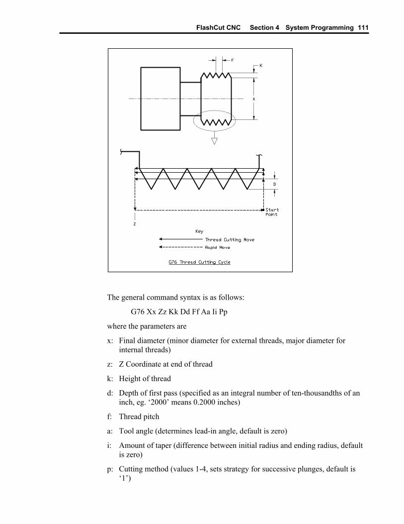
FlashCut CNC Section 4 System Programming 111
The general command syntax is as follows:
G76 Xx Zz Kk Dd Ff Aa Ii Pp
where the parameters are
x: Final diameter (minor diameter for external threads, major diameter for internal threads)
z: Z Coordinate at end of thread
k: Height of thread
d: Depth of first pass (specified as an integral number of ten-thousandths of an inch, eg. ‘2000’ means 0.2000 inches)
f: Thread pitch
a: Tool angle (determines lead-in angle, default is zero)
i: Amount of taper (difference between initial radius and ending radius, default is zero)
p: Cutting method (values 1-4, sets strategy for successive plunges, default is ‘1’)

FlashCut CNC Section 4 System Programming 112
The required parameters are Z, X, K, D, F. Note that in the diagram above, the ‘A’ and ‘I’ parameters are zero, and the cutting method is ‘1’ (all default values).
Cutting a thread generally requires several passes. The ‘P’ parameter controls the depth, starting position and plunge angle of each pass, as shown in the following diagrams. For all four cutting methods shown in the diagrams below, the ‘A’ parameter is shown as nonzero to illustrate its affect. When ‘A’ is zero, the plunges are straight into the workpiece, along the X axis, as shown in the diagram above.
The settings on the Threading panel of the Configuration dialog box also affect the cutting passes as follows.
Minimum Depth of Cut – The incremental depth of any pass will greater than or equal to this value (except for the final pass and any spring passes).
FlashCut CNC Section 4 System Programming 113
Final Pass Depth of Cut – Incremental depth of the final pass (finishing pass).
Spring Passes – Number of additional passes performed at the same depth as the final pass.
WARNING: The Feed Hold button (and feed hold input lines) are disabled during a threading pass, since it is not safe to stop moving the tool while the part is still turning. If you need to stop motion during a cutting pass, turn off power to the spindle and Signal Generator.
Example (assumes Minimum Depth of Cut is 0.010, Final Pass Depth of Cut is 0.005, Spring Passes is set to 1):
G00 X0.75 Move to the Start Point
G76 X1.0 Z-2 K0.125 D500 F0.2
Performs a total of 8 threading passes (including 1 spring pass) to make a two inch long thread with minor diameter 1.0, major diameter 1.25, at 5 turns per inch. By default the cutting method is P1, the tool angle is 0, and there is no taper. The first pass is cut at a depth of 0.05.
Note that the F parameter does not set the feedrate for subsequent non-threading moves, since its meaning is different from the standard F command.
G90 Absolute Positioning Mode The G90 command puts the system into absolute positioning mode. All XYZA coordinates are treated as points relative to Program Zero (or a local coordinate system set by the G52 command). This command stays in effect until a G91 command occurs.
Note that absolute positioning is the default positioning mode for FlashCut. It is not necessary to include this command in your G-code file if all your moves are absolute.
G91 Incremental Positioning Mode The G91 command puts the system into incremental positioning mode. All XYZA coordinates are treated as incremental move distances. This command stays in effect until a G90 command occurs.
Example:
G01 X1.0 Y3.0 Z-1.5 F12 Moves the tool to program coordinates X=1.0, Y=3.0, Z=-1.5 (G90 is assumed)
G91 All XYZA coordinates after this command will be interpreted as incremental distances.
G01 X1.0 Y2.0 Z-0.5 Moves the tool a distance of X=1.0, Y=2.0, Z=-0.5 from the current tool location (this corresponds to the program coordinates X=2.0, Y=5.0 Z=-2.0)
FlashCut CNC Section 4 System Programming 114
G02 X1.0 Y-1.0 I0.5 J-0.5 Moves the tool using counter-clockwise circular interpolation to the program coordinates X=3.0, Y=4.0, Z=-2.0 with a center point at program coordinates X=2.5, Y=4.5, Z=-2.0.
G90 All XYZA coordinates after this command will be interpreted as program coordinates
G01 X1.0 Y2.0 Z-0.5 Moves the tool to program coordinates X=1.0, Y=2.0, Z=-0.5
M00 Program Pause
The M00 command pauses processing of the G-Code program. By default, FlashCut displays a dialog box to inform you that it has paused processing. You can control whether or not this dialog box appears using the Message on M00 Program Pause checkbox in the G-Code panel of the Configuration dialog box.
If you want to display a specific message to the operator, you can add the message in quotes after the M00:
M00 “[message]”
Example: M00 “Place a new blank in the fixture”
M01 Optional Program Pause The M01 command is identical to the M00 command, except that it may be deactivated when desired. To control activation of the M01 command, use the Execute M01 checkbox on the G-Code panel of the Configuration dialog box. When the checkbox is unchecked, FlashCut ignores the command.
M30, M30.1 End of Program The M30 command ends processing of the G-Code program and automatically resets the program to the first executable line. The M30.1 command is similar to M30 except it also restarts the G-Code program. This allows you to run a program over and over indefinitely.
M98, M99, M02 Subroutine Commands Subroutines allow you to eliminate repetitive programming. FlashCut supports the use of subroutines with the M98, M99, and M02 (or M30) commands. Use of these commands is best explained through a simple example. The following G-code program uses one subroutine called "mysub":
FlashCut CNC Section 4 System Programming 115
Example:
G01 X1 Y1 F10 First line of main program
M98 Pmysub Jump to subroutine “mysub”
G01 X0 Y0 Continued execution after “mysub” ends
M02 End of main program
Omysub First line of the subroutine called “mysub”
G01 X2 Y2 Continued execution within the subroutine
M99 End of subroutine “mysub”
In the main program, the M98 command causes program execution to jump to the first line of the subroutine named "mysub". Notice that the letter "P" must immediately precede the name of the subroutine with no spaces.
The subroutine definition begins with the letter "O" followed immediately by the subroutine name with no spaces. The subroutine must end with the M99 command as shown. M99 causes program execution to jump back to the main program, continuing with the line immediately following the M98 line (G01 X0 Y0 above).
When subroutines are used, the main program must end with M02 or M30, the "End of Program" commands. Subroutine names may use any number of alpha-numeric characters. You can "nest" subroutines as much as you like, meaning one subroutine may call another subroutine, which in turn may call another subroutine, and so on.
To call the same subroutine multiple times, include the L parameter as shown below.
Example:
M98 Pmysub L10 Execute subroutine “mysub” 10 times
This feature provides a simple means to repetitively loop through any block of G-Code. Just place the G-Code in a subroutine, then call the subroutine with the L parameter set to the number of loops required.
It’s sometimes convenient to place subroutines in files separate from the main G-Code file. These files are called included files, and you may use as many as you like. You must list each included file at the top of the main G-Code file using the following syntax:
#[file path and name]
Once a file has been included in the main G-Code file, FlashCut treats the included file’s subroutines the same as if they were listed at the bottom of the main G-Code file. If you leave out the path, FlashCut will look for the file in the same folder as the main G-Code file.
FlashCut CNC Section 4 System Programming 116
Example:
Main G-Code File (Engraves “A B”) #C:\GCODE\ALPHABET.FGC
G00 X0 Y0
M98 PmakeA
G00 X1 Y0
M98 PmakeB
M02
ALPHABET.FGC File OmakeA
G91
[Incremental G-Code to cut the letter “A”]
G90
M99
OmakeB
G91
[Incremental G-Code to cut the letter “B”]
G90
M99
Notice that the syntax for calling the included subroutines is the same as for calling subroutines listed in the main G-Code file.
You may create as many subroutines as you like in the main G-Code file and all included files, but each must have a unique name.
FlashCut’s support for included files lets you create a library of reusable subroutines that you can apply to various projects and jobs.
M100, M101 Wait for Input Line
The M100 and M101 commands wait for an input line to reach a desired state as follows:
M100 Wait for normal state
M101 Wait for tripped state
The Wiring setting in the Input Lines panel of the Configuration dialog box affects the behavior of these commands as follows:
FlashCut CNC Section 4 System Programming 117
Wiring Setting M100 Waits For Input Line to be...
M101 Waits For Input Line to be...
Normally Closed Closed Open
Normally Open Open Closed
The command syntax is as follows:
M100 Ix “[optional custom message to operator]”
M101 Ix “[optional custom message to operator]”
where x is the number of the input line to monitor.
Examples:
M100 I2 System waits for input line 2 to reach the normal state, displays standard message if timeout is reached
M101 I7 “Low air pressure” System waits for input line 7 to become tripped, displays customized message if timeout is reached
You must define the specified input line as “Control” in the Switch Function pull-down menu, in the Input Lines panel of the Configuration dialog box (see “Input Line Settings” in the Initial Setup section for more details).
FlashCut uses debounce for these commands. For a switch to successfully reach a desired state, it must hold that state continuously for the debounce duration. You can set the M100/M101 Debounce time in the G-Code panel of the Configuration dialog box.
The M100 and M101 commands time out once the maximum allowable time has passed and the input line has not reached the desired state. When the commands time out, FlashCut halts processing of the G-Code program and displays a message to the operator. You can set the M100/M101 Timeout duration in the G-Code panel of the Configuration dialog box.
A typical use for these commands is detecting completed motion of an auxiliary device, such as an indexer or air cylinder.
M03, M05, M07, M08, M09, M50, M51, MXX Auxiliary Device Control Using the M-Code Definitions panel of the Configuration dialog box you can define up to 50 M-Codes to turn on or off various devices via the output lines. You can also define M-Codes to digitally control external devices (using a group of output lines as digital input into the control lines of the device). See “M-Code Definitions” in the Initial Setup section for details on how to set up the M codes.
When FlashCut processes an M-Code that sets output lines, if the current output line state already reflects the M-Code’s intended action, FlashCut skips the M-Code, including any associated delay. For example, if the spindle is on, and

FlashCut CNC Section 4 System Programming 118
FlashCut processes an M-Code to turn on the spindle, the delay associated with turning on the spindle (eg. 2 seconds) is skipped.
Typical M codes include:
M03 Spindle On
M05 Spindle Off
M07 Mist Coolant On
M08 Flood Coolant On
M09 Coolant Off
M50 Plasma On
M51 Plasma Off
F Set Feedrate Command The F command specifies the feedrate. The feedrate set with the F command is modal (stays in effect until another F command occurs).
For all linear moves, specify the feedrate in inches/minute for English units and millimeters/minute for Metric units.
Example:
G01 X4.0 Y3.0 Z1.0 F7.0 Moves the tool to program coordinates X=4.0, Y=3.0, Z=1.0 at a feedrate of 7.0 in/min
For any move that includes the A (rotary) axis, specify the feedrate either as a linear feedrate (length/minute) or rotary feedrate (degrees/minute), depending on your setting in the G-Codes panel of the Configuration dialog box. Please see the detailed explanation of rotary feedrates under “G01 Linear Interpolated Feedrate Move” above.
S Set Spindle Speed Command
The S command sets the spindle speed to the indicated value (specified in RPM).
Example:
S1000 Sets the spindle speed to 1000 rpm
See “Analog Output Line Settings” in Initial Setup for details on how FlashCut converts the desired RPM to an analog output signal.

FlashCut CNC Section 4 System Programming 119
Program Comments
You can add comments to your program by enclosing them in parentheses. FlashCut ignores anything enclosed in parentheses as shown below.
Example: (Move to beginning of the next feature)
G00 X1.0 Y3.0 (Ready to move Z axis down)
G00 Z-1.5
(Begin next feature)
G01 Z-1.6 F8
G01 X3.0 Y7.5
Optional Line
The optional line command is a forward slash (‘/’) at the start of a G-Code line. FlashCut only executes the line if the Execute Optional G-Code Lines checkbox is checked, on the G-Code panel of the Configuration dialog box. If the checkbox is unchecked, FlashCut ignores the line.
Example: G00 X2 Y4
/G00 Z1 This line not always executed
G00 X3 Y5
Advanced Programming Reference FlashCut provides a number of advanced programming features, allowing you to create more flexible and powerful G-Code programs.
Values
In every G-Code example up to this point, all values were literal values. A literal value is one that’s typed into the G-Code program and cannot change. Examples of literal values are:
1
2.33
“Please close the door”
An example of these values used in G-Code is: T1
G00 X2.33
M00 “Please close the door”
FlashCut CNC Section 4 System Programming 120
Variables
In addition to literal values, the FlashCut G-Code interpreter understands variables.
A variable is a placeholder for a value. There are two categories of variables in Flashcut: System and User. System variables are defined and set by the FlashCut software itself. These variables represent status values in the software, and therefore allow you to access information about the current state of the program. Most system variables cannot be modified in a G-Code program. However, all system variables can be read in a G-Code program. The system variables currently supported are:
• #CurrTool – This variable represents the number of the tool currently loaded. Its value is 0 if no tool is loaded. This value can be modified in a G-Code program. It is typically modified in a tool change macro.
• #NextTool – This variable represents the number of the tool that will be loaded on the next tool change command (M06). Its value is 0 if no tool has been specified with the T command. This value can be modified in a G-Code program.
• #CurrFeedrate – This variable represents the current feedrate. This value can be modified in a G-Code program.
• #TlChgFeedrate – This variable represents the feedrate at which the controlled rate portions of an automatic tool change will occur.
• #TlChgCheckPower – This variable represents the state of the Monitor Tool Chuck Power checkbox on the Tool Change panel of the Configuration dialog box (checked = true).
• #TlChgPowerInputLine – This variable represents the setting of the Input Line text box on the Tool Change panel of the Configuration dialog box.
• #TlChgCheckPowerInputNormal – This variable represents the setting of the Power On State pull-down menu on the Tool Change panel of the Configuration dialog box (Normal = true).
• #Tool – This is an array variable that is used to access properties of any configured tool.
• #RefPoint – This is an array variable that is used to access properties of any defined reference point.
• #FixOff – This is an array variable that is used to access properties of any defined fixture offset.
• #TlRackPos – This is an array variable that is used to access the properties of any tool rack position.
• #Machine – This variable represents the current position of the machine tool in machine coordinates.
FlashCut CNC Section 4 System Programming 121
• #Program – This variable represents the current position of the machine tool in program coordinates.
• #ProgZeroOff – This variable represents the offset from the machine coordinate system to the program coordinate system.
• #ToolOff – This variable represents the tool offset currently in effect.
#Tool, #RefPoint, #FixOff, and #TlRackPos are array variables. Array variables are discussed later in this section.
#Machine, #Program, #ProgZeroOff, and #ToolOff are runtime variables. This means that their values are not accessible in a G-Code program. Rather, these variables are intended to be used in the Tool Length Formula (on the Tool Length Sensing panel of the Configuration dialog box).
In addition to the above variables, there are several general-purpose system variables available that do not represent any system status values. These variables have been provided for use in macros. You are free to set and read these variables as desired.
• #SysInteger1 - #SysInteger8 – Eight system-declared INTEGER variables.
• #SysReal1 - #SysReal8 – Eight system-declared REAL variables.
• #SysBoolean1 - #SysBoolean8 – Eight system-declared BOOLEAN variables.
• #SysString1 - #SysString8 – Eight system-declared STRING variables.
User variables are defined and maintained by the G-Code programmer. In order to use a User variable, you must first declare it with a simple statement that includes the type of the variable and its name, as in this example:
GLOBAL INTEGER #Count
In the above statement, the word “GLOBAL” indicates the scope of the variable (more on that later), “INTEGER” is the type, and “#Count” is the variable name. The types supported by FlashCut are:
• INTEGER – These are whole numbers (ie. numbers without decimal points). They can be positive or negative (or zero).
• REAL – These are rational (or fractional) numbers (ie. numbers with decimal points). They can be positive or negative (or zero).
• BOOLEAN – Variables of this type can have one of two values: TRUE or FALSE.
• STRING – Variables of this type represent text.
FlashCut CNC Section 4 System Programming 122
Example declarations: GLOBAL INTEGER #Index
GLOBAL REAL #X
GLOBAL BOOLEAN #IsDone
GLOBAL STRING #Message
As with all other words in a FlashCut G-Code program, the case of the letters does not matter. In other words, these two declarations are the same:
GLOBAL REAL #X
Global REal #x
If these two lines appeared in the same G-Code file, an error would be reported because the same variable is being declared twice.
Variable names can be any sequence of letters or numbers or the underscore character (_), but must always start with a number sign (#). The following are all legal variable names:
#X
#Index
#3rdAxis
#Is_Done
The word “GLOBAL” in a variable declaration indicates the scope, or context, of the variable. A variable with GLOBAL scope can have its value changed or retrieved anywhere in the G-Code program, even in a file that is included into the program. GLOBAL variables must be declared before any line of G-Code other than lines that include files using #.
If the word GLOBAL is omitted from the variable declaration, that variable is considered to have local scope. This means that the variable’s value can only be changed or retrieved in the same subroutine in which it was declared.
Currently, FlashCut only supports GLOBAL variables, so the word “GLOBAL” is optional. Future releases of FlashCut will support local variables. In these releases, the word GLOBAL will be required to indicate variables with global scope.
One or more variables can be declared on the same line. For example, REAL #X #Y #Z
declares three variables, #X, #Y, and #Z, that are all of type REAL. When declaring more than one variable on the same line, the variable names must be separated by spaces.
FlashCut CNC Section 4 System Programming 123
The value of a variable can be set by using the assignment operator. The assignment operator is an equals sign (=). Variables can be assigned literal values, as shown below:
INTEGER #Count
#Count = 0
The above code declares an integer variable called #Count, and then assigns #Count the literal value of 0. The process is similar for all variable types.
REAL #X #Y
BOOLEAN #IsDone
STRING #Message
#X = 1.0
#Y = 2.1
#IsDone = FALSE
#Message = “Please make sure the enclosure is closed.”
A variable can be used in place of a literal value in a G-Code file. For instance, REAL #X #Y
#X = 1.0
#Y = 2.1
G00 X#X Y#Y
will cause a rapid move to X = 1.0, Y = 2.1. Here are more examples of variable use:
INTEGER #ToolNumber
STRING #Message
#ToolNumber = 1
M06 T#ToolNumber
#Message = “Please make sure the enclosure is closed.”
M00 #Message
Some variables types will be automatically converted to the correct type as necessary. For instance, motion commands take REAL type parameters, but INTEGER type parameters will be automatically converted. Example:
INTEGER #X #Y
#X = 1
#Y = 2
G00 X#X Y#Y
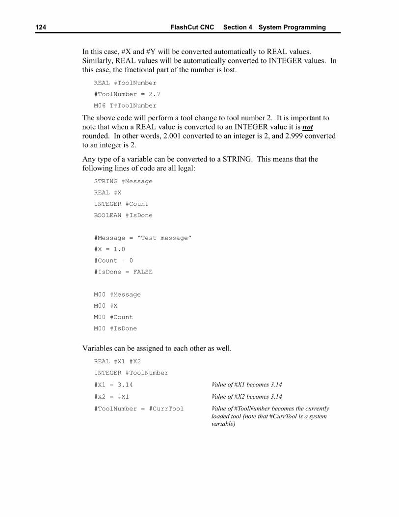
FlashCut CNC Section 4 System Programming 124
In this case, #X and #Y will be converted automatically to REAL values. Similarly, REAL values will be automatically converted to INTEGER values. In this case, the fractional part of the number is lost.
REAL #ToolNumber
#ToolNumber = 2.7
M06 T#ToolNumber
The above code will perform a tool change to tool number 2. It is important to note that when a REAL value is converted to an INTEGER value it is not rounded. In other words, 2.001 converted to an integer is 2, and 2.999 converted to an integer is 2.
Any type of a variable can be converted to a STRING. This means that the following lines of code are all legal:
STRING #Message
REAL #X
INTEGER #Count
BOOLEAN #IsDone
#Message = “Test message”
#X = 1.0
#Count = 0
#IsDone = FALSE
M00 #Message
M00 #X
M00 #Count
M00 #IsDone
Variables can be assigned to each other as well.
REAL #X1 #X2
INTEGER #ToolNumber
#X1 = 3.14 Value of #X1 becomes 3.14
#X2 = #X1 Value of #X2 becomes 3.14
#ToolNumber = #CurrTool Value of #ToolNumber becomes the currently loaded tool (note that #CurrTool is a system variable)

FlashCut CNC Section 4 System Programming 125
Some system variables represent objects, rather than simple types. The system variables in this category are #Machine, #Program, #ProgZeroOff, and #ToolOff. Here is a description of the properties of each:
• Machine
o X – the current position on the X axis in machine coordinates
o Y – the current position on the Y axis in machine coordinates
o Z – the current position on the Z axis in machine coordinates
o A (W) – the current position on the A (or W) axis in machine coordinates
• Program
o X – the current position on the X axis in program coordinates
o Y – the current position on the Y axis in program coordinates
o Z – the current position on the Z axis in program coordinates
o A (W) – the current position on the A (or W) axis in program coordinates
• Program Zero Offset
o X – the current offset from machine to program coordinates on the X axis
o Y – the current offset from machine to program coordinates on the Y axis
o Z – the current offset from machine to program coordinates on the Z axis
o A (W) – the current offset from machine to program coordinates on the A (or W) axis
• Tool Offset
o X – the currently applied tool offset on the X axis
o Y – the currently applied tool offset on the Y axis
o Z – the currently applied tool offset on the Z axis
Since these variables represent objects rather than simple types, there is a special way to use them. The values represented by these variables can be accessed by specifying the desired property using a period (dot) followed by the property name. For instance,
#Machine.X
is how you would access the current position on the X axis in machine coordinates.

FlashCut CNC Section 4 System Programming 126
Array variables are groups of variable values that are indexed. They can be accessed by supplying the desired index value (position in the array). An array variable is declared in much the same way as any other variable, except that the size of the group, also known as the dimension of the array, must be specified. Example:
REAL #XPositions{5}
The above code declares a REAL array variable called #XPosition that contains 5 values. Arrays can be created for any type (INTEGER, REAL, BOOLEAN, or STRING). The name of the array variable must be followed by a pair of braces, {}, that surround a number. The lowest number allowed for an array dimension is 1. An array of 1 is exactly the same as a non-array variable. The highest number allowed for an array dimension is 10,000. In other words,
INTEGER #Val{0}
BOOLEAN #MyArray{10001}
will both result in errors when the program is loaded.
An array value is accessed in the same manner as any other variable, except that the index, must be specified. For example,
REAL #XPositions{3} #YPositions{3}
#XPositions{1} = 0.0
#XPositions{2} = 1.0
#XPositions{3} = 2.0
#YPositions{1} = 4.0
#YPositions{2} = 3.0
#YPositions{3} = 2.0
The lowest index number is 1, and the highest index number is the dimension of the array variable. In other words, if an array variable is declared with a dimension of 3, the highest index number is 3.
The index itself can be a literal value or a variable value. REAL #XPositions{3} #YPositions{3}
#XPositions{#CurrTool} = 0.0
#YPositions{#CurrTool} = 2.0
In the above example, if no tool is loaded (ie. #CurrTool = 0), an error will result because the lowest index number is 1. Similarly, if #CurrTool = 4 or higher, an error will result because both array variables were declared with a dimension of 3.
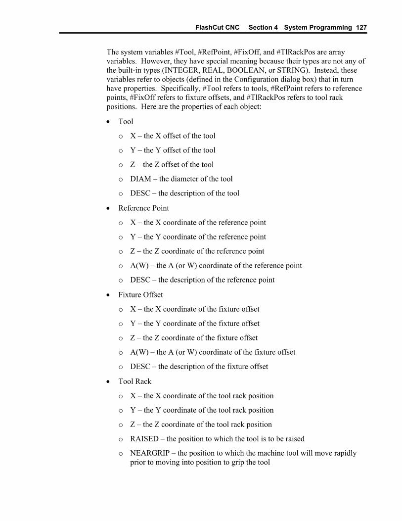
FlashCut CNC Section 4 System Programming 127
The system variables #Tool, #RefPoint, #FixOff, and #TlRackPos are array variables. However, they have special meaning because their types are not any of the built-in types (INTEGER, REAL, BOOLEAN, or STRING). Instead, these variables refer to objects (defined in the Configuration dialog box) that in turn have properties. Specifically, #Tool refers to tools, #RefPoint refers to reference points, #FixOff refers to fixture offsets, and #TlRackPos refers to tool rack positions. Here are the properties of each object:
• Tool
o X – the X offset of the tool
o Y – the Y offset of the tool
o Z – the Z offset of the tool
o DIAM – the diameter of the tool
o DESC – the description of the tool
• Reference Point
o X – the X coordinate of the reference point
o Y – the Y coordinate of the reference point
o Z – the Z coordinate of the reference point
o A(W) – the A (or W) coordinate of the reference point
o DESC – the description of the reference point
• Fixture Offset
o X – the X coordinate of the fixture offset
o Y – the Y coordinate of the fixture offset
o Z – the Z coordinate of the fixture offset
o A(W) – the A (or W) coordinate of the fixture offset
o DESC – the description of the fixture offset
• Tool Rack
o X – the X coordinate of the tool rack position
o Y – the Y coordinate of the tool rack position
o Z – the Z coordinate of the tool rack position
o RAISED – the position to which the tool is to be raised
o NEARGRIP – the position to which the machine tool will move rapidly prior to moving into position to grip the tool

FlashCut CNC Section 4 System Programming 128
o NEARRELEASE – the position to which the machine tool will move rapidly prior to moving into position to release the tool
o GRIP – the position at which the machine tool will grip the tool in the chuck
o RELEASE – the position at which the machine tool will release the tool from the chuck
Because #Tool, #RefPoint, #FixOff, and #TlRackPos refer to objects, they cannot be accessed directly. However, each individual property of these objects can be retrieved. This is done by adding a period (dot) after the variable name, and then the name of the property. For example,
G00 X#RefPoint{1}.X
This will cause a rapid move on the X axis to the X coordinate of reference point #1. Similarly,
M00 #Tool{1}.DESC
will display a message containing the description of tool number 1.
Since #CurrTool and #NextTool are INTEGERs, you could display the description of the currently loaded tool by typing:
M00 #Tool{#CurrTool}.DESC
Operators In addition to declaring variables, setting their values, and using their values, FlashCut supports the use of several operators to make G-Code programs more flexible and powerful. There are mathematical, grouping, string, and comparison operators.
Mathematical
The mathematical operators work for INTEGER and REAL values. They are:
+ adds two values
- subtracts two values
* multiplies two values
/ divides two values
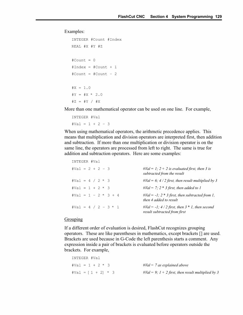
FlashCut CNC Section 4 System Programming 129
Examples: INTEGER #Count #Index
REAL #X #Y #Z
#Count = 0
#Index = #Count + 1
#Count = #Count – 2
#X = 1.0
#Y = #X * 2.0
#Z = #Y / #X
More than one mathematical operator can be used on one line. For example, INTEGER #Val
#Val = 1 + 2 – 3
When using mathematical operators, the arithmetic precedence applies. This means that multiplication and division operators are interpreted first, then addition and subtraction. If more than one multiplication or division operator is on the same line, the operators are processed from left to right. The same is true for addition and subtraction operators. Here are some examples:
INTEGER #Val
#Val = 2 + 2 – 3 #Val = 1; 2 + 2 is evaluated first, then 3 is subtracted from the result
#Val = 4 / 2 * 3 #Val = 6; 4 / 2 first, then result multiplied by 3
#Val = 1 + 2 * 3 #Val = 7; 2 * 3 first, then added to 1
#Val = 1 – 2 * 3 + 4 #Val = -1; 2 * 3 first, then subtracted from 1, then 4 added to result
#Val = 4 / 2 – 3 * 1 #Val = -1; 4 / 2 first, then 3 * 1, then second result subtracted from first
Grouping
If a different order of evaluation is desired, FlashCut recognizes grouping operators. These are like parentheses in mathematics, except brackets [] are used. Brackets are used because in G-Code the left parenthesis starts a comment. Any expression inside a pair of brackets is evaluated before operators outside the brackets. For example,
INTEGER #Val
#Val = 1 + 2 * 3 #Val = 7 as explained above
#Val = [1 + 2] * 3 #Val = 9; 1 + 2 first, then result multiplied by 3
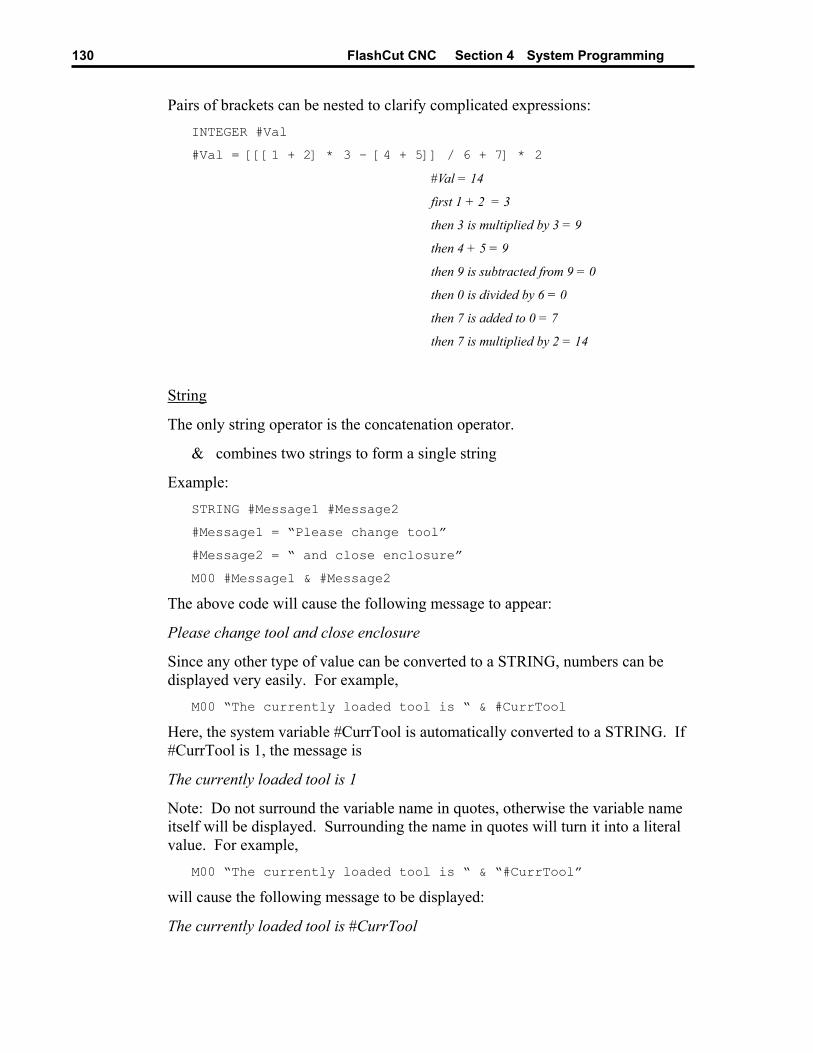
FlashCut CNC Section 4 System Programming 130
Pairs of brackets can be nested to clarify complicated expressions: INTEGER #Val
#Val = [[[1 + 2] * 3 – [4 + 5]] / 6 + 7] * 2
#Val = 14
first 1 + 2 = 3
then 3 is multiplied by 3 = 9
then 4 + 5 = 9
then 9 is subtracted from 9 = 0
then 0 is divided by 6 = 0
then 7 is added to 0 = 7
then 7 is multiplied by 2 = 14
String
The only string operator is the concatenation operator.
& combines two strings to form a single string
Example: STRING #Message1 #Message2
#Message1 = “Please change tool”
#Message2 = “ and close enclosure”
M00 #Message1 & #Message2
The above code will cause the following message to appear:
Please change tool and close enclosure
Since any other type of value can be converted to a STRING, numbers can be displayed very easily. For example,
M00 “The currently loaded tool is “ & #CurrTool
Here, the system variable #CurrTool is automatically converted to a STRING. If #CurrTool is 1, the message is
The currently loaded tool is 1
Note: Do not surround the variable name in quotes, otherwise the variable name itself will be displayed. Surrounding the name in quotes will turn it into a literal value. For example,
M00 “The currently loaded tool is “ & “#CurrTool”
will cause the following message to be displayed:
The currently loaded tool is #CurrTool
FlashCut CNC Section 4 System Programming 131
Several concatenation operators can be used on the same line. This allows complicated text messages to be built. Example:
M00 “Tool #“ & #CurrTool &
“ will be replaced by tool #” & #NextTool
If the current tool is 1 and the next tool is 2, the message displayed will be:
Tool #1 will be replaced by tool #2
Mathematical operators can appear on the same line as the concatenation operator. If this is the case, all mathematical operations are evaluated first. The results of the mathematical operations are converted to strings and the concatenation takes place. Example:
M00 “The result “ & 1 + 2 &
“ was obtained by adding 2 to 1”
The expression 1 + 2 is evaluated first, then the result is converted to a STRING and concatenated with the string literals. The message that is displayed is:
The result 3 was obtained by adding 2 to 1
Comparison
The comparison operators work for any type of value, but both values must be the same type (or must be convertible to the same type). The comparison operators are:
= TRUE if both values are equal, FALSE if not
!= TRUE if the values are different, FALSE if they are the same
> TRUE if the value to the left of the operator is greater than the value to the right, FALSE if not
>= TRUE if the value to the left of the operator is greater than or equal to the value to the right, FALSE if not
< TRUE if the value to the left of the operator is less than the value to the right, FALSE if not
<= TRUE if the value to the left of the operator is less than or equal to the value to the right, FALSE if not
Examples of comparison operator use appear in the following sections.
Flow Of Control Flow of control commands let you build simple or complex logic into your G-Code programs. FlashCut provides two types of flow of control: Branches and Loops. Branches make it possible for a G-Code program to execute different sections of the code based on a condition. The syntax for a Branch is:

FlashCut CNC Section 4 System Programming 132
IF condition THEN
…
ENDIF
where condition is a Boolean value or expression. If condition is TRUE, the code between the IF line and the ENDIF line is executed. If condition is FALSE, the code is skipped and execution continues with the first line after ENDIF.
At times there is a need to execute some code if a condition is true and execute different code if that condition is FALSE. This can be done by using an ELSE statement:
IF condition THEN
…
ELSE
…
ENDIF
In this case, the code between the IF and the ELSE is executed if condition is TRUE, and the code between ELSE and ENDIF is executed if condition is FALSE. Example,
IF #NextTool = 1 THEN
M00 “Please load tool #1”
ELSE
M00 “Please load tool #2”
ENDIF
In this example, if #NextTool (a system variable) is 1, the user will see a message to load tool number 1; otherwise a message to load tool number 2 will appear. The above example includes an example of the use of the ‘=’ comparison operator as well. Remember that the comparison operator result is BOOLEAN (that is, TRUE or FALSE).
For even greater flexibility, additional conditions can be specified: IF #NextTool = 1 THEN
M00 “Please load tool #1”
ELSEIF #NextTool = 2 THEN
M00 “Please load tool #2”
ELSEIF #NextTool = 3 THEN
M00 “Please load tool #3”
ELSE
M00 “An invalid tool was selected”
ENDIF
The above example lets you display different messages based on the next tool to be loaded. Note that only one ENDIF was necessary. Also, note that THEN is required for each IF or ELSEIF.
FlashCut CNC Section 4 System Programming 133
IF statements can be nested. This means that inside a block of code between IF and ENDIF, one or more IFs can appear. For example,
IF #CurrTool > 0 THEN
IF #CurrTool = 1 THEN
M00 “The first tool is loaded”
ELSEIF #CurrTool = 2 THEN
M00 “The second tool is loaded”
ENDIF
ELSE
IF #CurrTool = 0 THEN
M00 “No tool is loaded”
ELSE
M00 “An invalid tool is loaded”
ENDIF
ENDIF
The lines of code between the first IF and the ELSE will be executed if the currently loaded tool number is greater than zero. The actual message that will appear depends on the number of the tool that is loaded. Notice that each block of code that starts with an IF eventually ends with an ENDIF. These pairings must be present, or an error will result when the G-Code file is loaded.
The other type of flow of control statement is the Loop. The syntax of the Loop is:
WHILE condition DO
…
ENDWHILE
The lines of code between the WHILE and the ENDWHILE will be executed as long as condition is TRUE. When condition is FALSE, the loop is exited and execution continues with the line of code following the ENDWHILE. Example,
INTEGER #Count
#Count = 0
WHILE #Count < 5 DO
M00 “Loop count = “ & #Count
#Count = #Count + 1
ENDWHILE
M00 “Not in loop”
This code will cause the following messages to appear:
FlashCut CNC Section 4 System Programming 134
Loop count = 0 Loop count = 1 Loop count = 2 Loop count = 3 Loop count = 4 Not in loop
If the condition specified in the loop is initially FALSE, the code in the loop will be skipped entirely.
Note: When creating loops, you must be careful to ensure that the loop condition will eventually be FALSE. Otherwise, an infinite loop will result and the program will never load. In the example above, omitting #Count = #Count + 1 creates an infinite loop.
Loops can appear inside other loops or branches. Branches can appear inside loops as well as other branches. Here’s a program that illustrates this as well as most of the other features discussed in this section.
(Use GLOBAL for these variables because their values
(are used in the main routine and in subroutines
GLOBAL INTEGER #Row
GLOBAL INTEGER #Col
GLOBAL REAL #XBase #YBase
GLOBAL REAL #RowSpacing #ColSpacing
GLOBAL REAL #XLoc #YLoc
GLOBAL BOOLEAN #MakeMeSmile
GLOBAL INTEGER #Result
(Don’t need GLOBAL for these variables because they
(are only used in the main routine
INTEGER #TotalRows
INTEGER #TotalCols
#TotalRows = 3
#TotalCols = 4
#XBase = 0.3
#YBase = 0.3
#RowSpacing = 0.8
#ColSpacing = 0.7
#Row=0
#Col=0

FlashCut CNC Section 4 System Programming 135
F10
WHILE #Row < #TotalRows DO
WHILE #Col < #TotalCols DO
M98 PUpdateLocation
#Result = #Col / 2
IF [#Col - #Result * 2] = 1 THEN
#MakeMeSmile = TRUE
ELSE
#MakeMeSmile = FALSE
ENDIF
M98 PSmiley
#Col=#Col+1
ENDWHILE
#Row=#Row+1
#Col=0
ENDWHILE
G00 X0 Y0
OUpdateLocation
#XLoc = #XBase + #Col * #ColSpacing
#YLoc = #YBase + #Row * #RowSpacing
G00 X#XLoc Y#YLoc
M99
OSmiley
G00 Z0
G91
G00 X-0.15 Y0.1
G01 Z-0.5
G02 I0.05
G01 Z0.5
G00 X0.3
G01 Z-0.5
G02 I-0.05
G01 Z0.5
G00 Y-0.2
G01 Z-0.5
IF #MakeMeSmile THEN
G02 X-0.3 I-0.15 J0.1
FlashCut CNC Section 4 System Programming 136
ELSE
G03 X-0.3 I-0.15 J-0.1
ENDIF
G01 Z0.5
G00 X-0.15 Y0.1
G01 Z-0.5
G02 I0.3
G90
G00 Z0
M99
Additional Keywords
In addition to the G-Code commands supported by Flashcut, there are some additional commands that you’ll specify using keywords. These keywords extend the capabilities of a G-Code program.
The EnableFO/DisableFO pair of keywords controls how feedrate override affects the G-Code program. These keywords are provided because there are cases when an override to the programmed feedrate cannot be tolerated. For example, in an automatic tool change macro, feedrate moves are often used. Overriding these feedrates might cause problems, so DisableFO can be used to ensure that the programmed feedrate will be enforced.
Here’s an example of EnableFO and DisableFO:
G00 X1 Y1
DisableFO Make sure the programmed feedrate is not overridden
G01 Z-0.5 F3
EnableFO Override is okay from this point
… Continue
In the above example, the programmer ensures that the tool will plunge at a rate of 3 inches/minute by disabling feedrate override before performing the plunge.
The SaveState/RestoreState pair of keywords causes certain state variables to be saved or restored. The specific status items affected are:
• Offset from Machine to Program coordinates (G92/G54/G55/G56/G57/G58/G59/G54.1/Zero Button/Set Button)
• Absolute vs. relative positioning (G90/G91)
• English vs. Metric units (G20/G21 and G70/G71)
• Canned cycle return position (G98/G99)
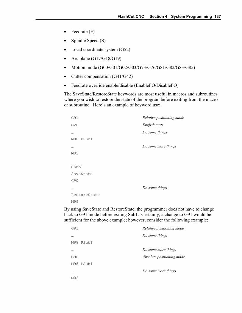
FlashCut CNC Section 4 System Programming 137
• Feedrate (F)
• Spindle Speed (S)
• Local coordinate system (G52)
• Arc plane (G17/G18/G19)
• Motion mode (G00/G01/G02/G03/G73/G76/G81/G82/G83/G85)
• Cutter compensation (G41/G42)
• Feedrate override enable/disable (EnableFO/DisableFO)
The SaveState/RestoreState keywords are most useful in macros and subroutines where you wish to restore the state of the program before exiting from the macro or subroutine. Here’s an example of keyword use:
G91 Relative positioning mode
G20 English units
… Do some things
M98 PSub1
… Do some more things
M02
OSub1
SaveState
G90
… Do some things
RestoreState
M99
By using SaveState and RestoreState, the programmer does not have to change back to G91 mode before exiting Sub1. Certainly, a change to G91 would be sufficient for the above example; however, consider the following example:
G91 Relative positioning mode
… Do some things
M98 PSub1
… Do some more things
G90 Absolute positioning mode
M98 PSub1
… Do some more things
M02
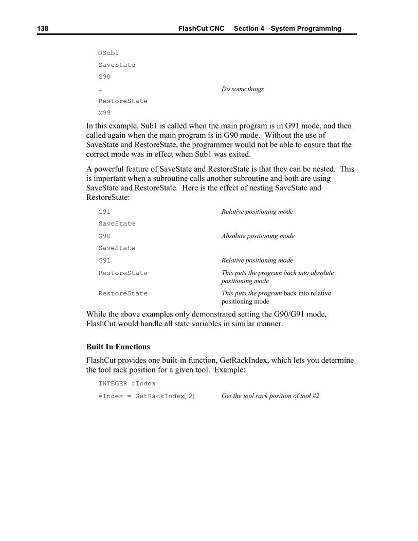
FlashCut CNC Section 4 System Programming 138
OSub1
SaveState
G90
… Do some things
RestoreState
M99
In this example, Sub1 is called when the main program is in G91 mode, and then called again when the main program is in G90 mode. Without the use of SaveState and RestoreState, the programmer would not be able to ensure that the correct mode was in effect when Sub1 was exited.
A powerful feature of SaveState and RestoreState is that they can be nested. This is important when a subroutine calls another subroutine and both are using SaveState and RestoreState. Here is the effect of nesting SaveState and RestoreState:
G91 Relative positioning mode
SaveState
G90 Absolute positioning mode
SaveState
G91 Relative positioning mode
RestoreState This puts the program back into absolute positioning mode
RestoreState This puts the program back into relative positioning mode
While the above examples only demonstrated setting the G90/G91 mode, FlashCut would handle all state variables in similar manner.
Built In Functions FlashCut provides one built-in function, GetRackIndex, which lets you determine the tool rack position for a given tool. Example:
INTEGER #Index
#Index = GetRackIndex[2] Get the tool rack position of tool #2

FlashCut CNC Section 5 Tutorial
139
Section 5. Tutorial
Starting FlashCut CNC To start FlashCut CNC, click on the Start button, select Programs, select FlashCut CNC 2, then select the FlashCut CNC 2 icon.
A dialog will appear asking you if you want to start with the Signal Generator Online. Choose the No, Start Offline button. If you’re running the Demo version, choose Continue.
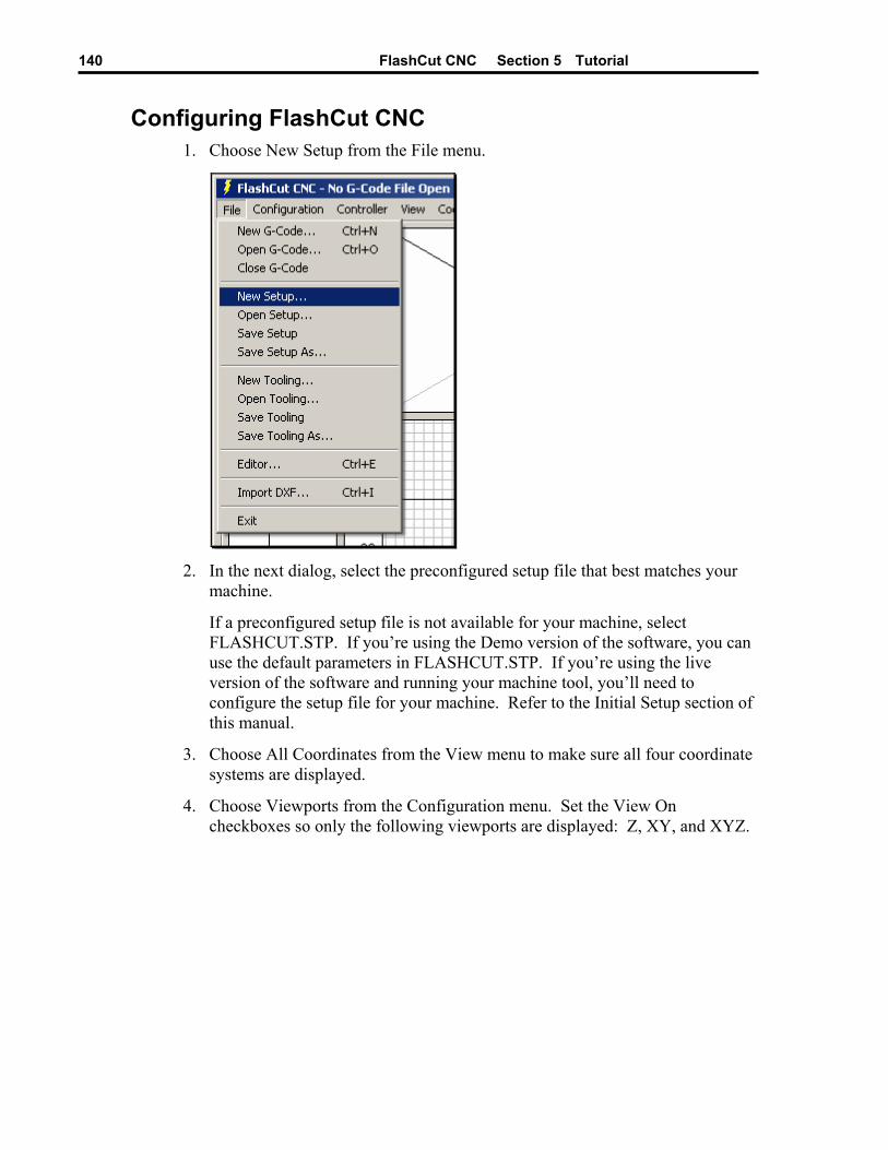
FlashCut CNC Section 5 Tutorial
140
Configuring FlashCut CNC 1. Choose New Setup from the File menu.
2. In the next dialog, select the preconfigured setup file that best matches your
machine.
If a preconfigured setup file is not available for your machine, select FLASHCUT.STP. If you’re using the Demo version of the software, you can use the default parameters in FLASHCUT.STP. If you’re using the live version of the software and running your machine tool, you’ll need to configure the setup file for your machine. Refer to the section of this manual.
Initial Setup
3. Choose All Coordinates from the View menu to make sure all four coordinate systems are displayed.
4. Choose Viewports from the Configuration menu. Set the View On checkboxes so only the following viewports are displayed: Z, XY, and XYZ.

FlashCut CNC Section 5 Tutorial
141
Loading a G-Code File 1. Choose Open G-Code from the File menu.
2. Double-click on the file TUTOR.FGC.
FlashCut will load TUTOR.FGC and the screen should now look like this:
Notice how the G-Code listing appeared in the Program Listing Box and a red outline of the toolpath appeared in the Toolpath Viewport Box.

FlashCut CNC Section 5 Tutorial
142
Viewing the Tool Path Before examining the toolpath display let’s zero the machine coordinates. To do this, choose the Zero (0) button to the right of the Machine label in the DRO Box. Choose Yes in the confirmation dialog that follows.
The machine coordinates, previously shown as N/A, will now be zeroed and a light blue box will outline the tool envelope in the Toolpath Viewport Box. Because All Fit Toolpath is checked in the View menu, you’ll only see a portion of the tool envelope boundary, as shown below.
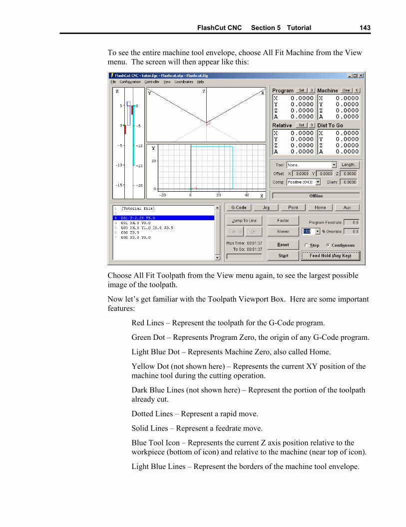
FlashCut CNC Section 5 Tutorial
143
To see the entire machine tool envelope, choose All Fit Machine from the View menu. The screen will then appear like this:
Choose All Fit Toolpath from the View menu again, to see the largest possible image of the toolpath.
Now let’s get familiar with the Toolpath Viewport Box. Here are some important features:
Red Lines – Represent the toolpath for the G-Code program.
Green Dot – Represents Program Zero, the origin of any G-Code program.
Light Blue Dot – Represents Machine Zero, also called Home.
Yellow Dot (not shown here) – Represents the current XY position of the machine tool during the cutting operation.
Dark Blue Lines (not shown here) – Represent the portion of the toolpath already cut.
Dotted Lines – Represent a rapid move.
Solid Lines – Represent a feedrate move.
Blue Tool Icon – Represents the current Z axis position relative to the workpiece (bottom of icon) and relative to the machine (near top of icon).
Light Blue Lines – Represent the borders of the machine tool envelope.

FlashCut CNC Section 5 Tutorial
144
Animating the G-Code File Now we’re ready to animate and verify the toolpath on the screen.
1. On the Controller menu, make sure Simulate when Offline is checked.
2. Choose the Zero (0) button next to the Program label, and then choose OK in the confirmation dialog box that follows. FlashCut sets all four program coordinates to 0. This simulates the tool being in the correct position before the G-Code program begins.
3. Choose the G-Code button in the Control Selection Box to make sure the G-Code Control Panel is displayed.
4. Select the Step radio button so FlashCut will execute the G-Code program one line at a time.
5. Choose the Start button and watch the blue tool move down the Z axis viewport. Notice that FlashCut has highlighted the next line in the Program Listing Box, indicating it has fully executed the first line.
6. Choose the Start button again. Notice the yellow dot, which represents the current position of the tool, and the solid blue line, which represents the cutting move just executed.
7. Select the Continuous radio button, and then choose the Start button again. The yellow dot moves along the toolpath to completion, leaving a blue trace behind.
Editing a G-Code File Now let’s get familiar with using the FlashCut editor.
1. Choose Editor from the File menu. The editor dialog box will appear.
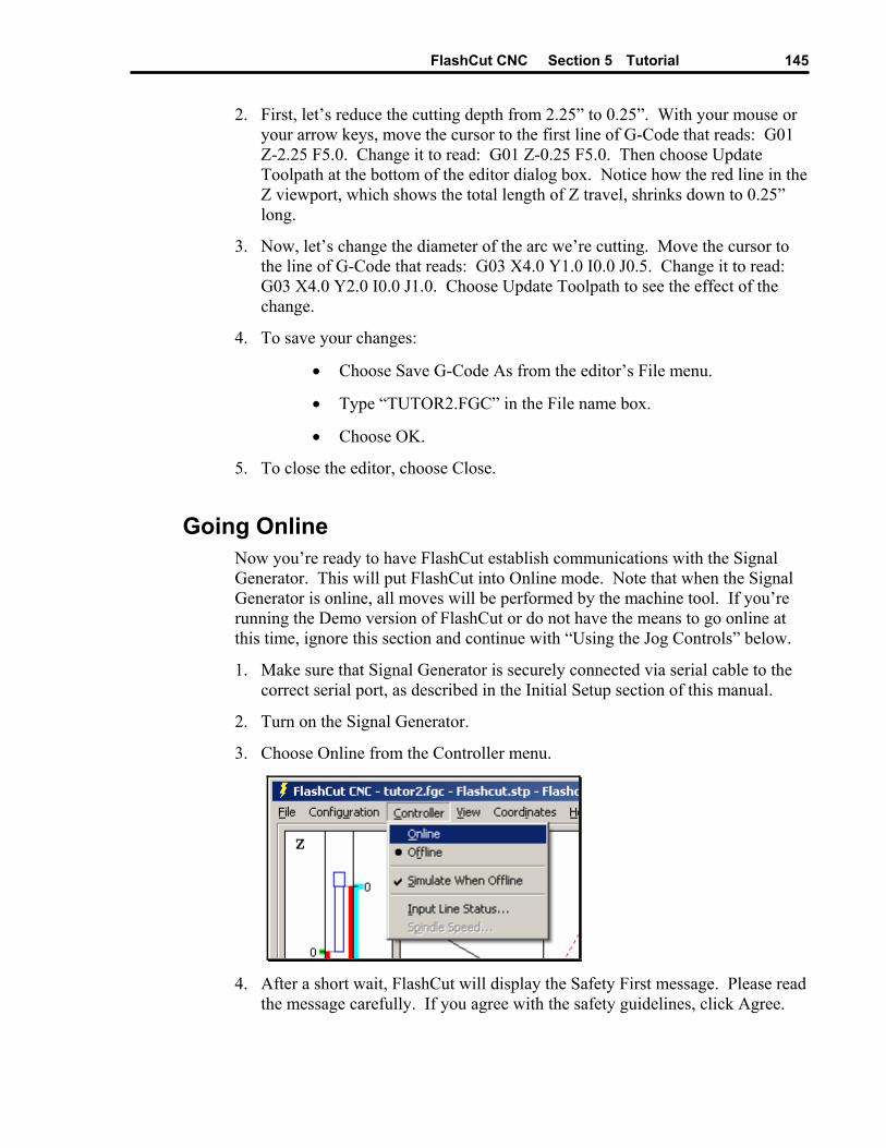
FlashCut CNC Section 5 Tutorial
145
2. First, let’s reduce the cutting depth from 2.25” to 0.25”. With your mouse or your arrow keys, move the cursor to the first line of G-Code that reads: G01 Z-2.25 F5.0. Change it to read: G01 Z-0.25 F5.0. Then choose Update Toolpath at the bottom of the editor dialog box. Notice how the red line in the Z viewport, which shows the total length of Z travel, shrinks down to 0.25” long.
3. Now, let’s change the diameter of the arc we’re cutting. Move the cursor to the line of G-Code that reads: G03 X4.0 Y1.0 I0.0 J0.5. Change it to read: G03 X4.0 Y2.0 I0.0 J1.0. Choose Update Toolpath to see the effect of the change.
4. To save your changes:
• Choose Save G-Code As from the editor’s File menu.
• Type “TUTOR2.FGC” in the File name box.
• Choose OK.
5. To close the editor, choose Close.
Going Online Now you’re ready to have FlashCut establish communications with the Signal Generator. This will put FlashCut into Online mode. Note that when the Signal Generator is online, all moves will be performed by the machine tool. If you’re running the Demo version of FlashCut or do not have the means to go online at this time, ignore this section and continue with “Using the Jog Controls” below.
1. Make sure that Signal Generator is securely connected via serial cable to the correct serial port, as described in the Initial Setup section of this manual.
2. Turn on the Signal Generator.
3. Choose Online from the Controller menu.
4. After a short wait, FlashCut will display the Safety First message. Please read
the message carefully. If you agree with the safety guidelines, click Agree.

FlashCut CNC Section 5 Tutorial
146
Using the Jog Controls The jog controls let you manually position the tool anywhere within the machine tool envelope.
1. Choose the Jog button in the Control Selection Box. FlashCut displays the Jog Control Panel.
2. Select the Slow and Contin (Continuous) radio buttons. The machine tool will move continuously at the Slow Jog Rate defined in the Feedrate/Ramping panel of the Configuration dialog box.
3. Check the machine tool to make sure there’s enough room to move the tool in the Z+ direction. If there is enough room, click down, hold and then release the Z+ Axis Jog button. Notice how the tool moved up and the Z program and relative coordinates changed. Also notice how the machine moved until you released the button. If the tool went down instead of up, change the Motor Direction for the Z axis in the Motor Signals panel of the Configuration dialog box. Note that when machine coordinates are being used, FlashCut will not let you move beyond the machine tool envelope. Also note that you can jog the machine using the keyboard. The controls are mapped as follows:
X+ Ctrl + Right Arrow Key
X- Ctrl + Left Arrow Key
Y+ Ctrl + Up Arrow Key
Y- Ctrl + Down Arrow Key
Z+ Ctrl + Page Up Key
Z- Ctrl + Page Down Key
A+ Ctrl + Plus (+) Key
A- Ctrl + Minus (-) Key
4. Try jogging in all directions on all axes, making sure you have enough room in the direction of travel before you choose each Axis Jog button.
5. Now select the Fast radio button and repeat the same exercise. The tool will move at the Fast Jog Rate defined in the Feedrate/Ramping panel of the Configuration dialog box.
6. Position the tool so there is at least 1” of room in the positive Z direction.
7. Now let’s set the current position as program coordinates X=0, Y=0, Z=1. First, choose the Set button next to the Program label in the DRO Box. Then choose the Zero X and Zero Y buttons. Finally, enter 1.0000 in the Z text box. Choose OK to exit the dialog.
8. Now let’s use the Axis Jog buttons to move the tool up exactly 1.0000”. It’s convenient to use three jog modes to do this: Fast Continuous, Slow Continuous and Slow Step.
9. While the jog rate is still set to Fast, move the tool up until the Z axis program coordinate is close to 2”.

FlashCut CNC Section 5 Tutorial
147
10. Now change the jog rate to Slow and do the same to get even closer to 2”.
11. Finally, change the jog mode to Step. FlashCut will move the tool exactly one step each time you choose one of the Axis Jog buttons. Repeatedly choose either the +Z or -Z Axis Jog button until the tool is exactly at program coordinate 2.0000 on the Z axis. Depending on the tool positioning resolution of your machine tool, you might not be able to reach 2.0000 exactly.
12. Now use the same process to move the tool exactly 0.5000 inches in the +X direction and 0.2500 inches in the +Y direction. The program coordinates should now read:
X: 0.5000
Y: 0.2500
Z: 2.0000
Setting Machine Zero You can set Machine Zero two ways: by jogging the tool to the corner of the machine tool envelope, or using the Seek Home button on the Home Control Panel. In this tutorial we will jog to a point and define it as Machine Zero.
1. Choose the Clear button next to the machine coordinate label in the DRO Box. This will clear the machine coordinates and remove the light blue machine tool envelope boundary.
2. Choose the Jog button in the Control Selection Box.
3. Jog the tool to 1/10” from the top of the Z axis.
4. Jog the table in the X- direction to about 1/10” from the end of travel.
5. Jog the table in the Y- direction to about 1/10” from the end of travel.
6. Choose the Zero (0) button to the right of the machine coordinate label. Then choose OK in the confirmation dialog box that follows.
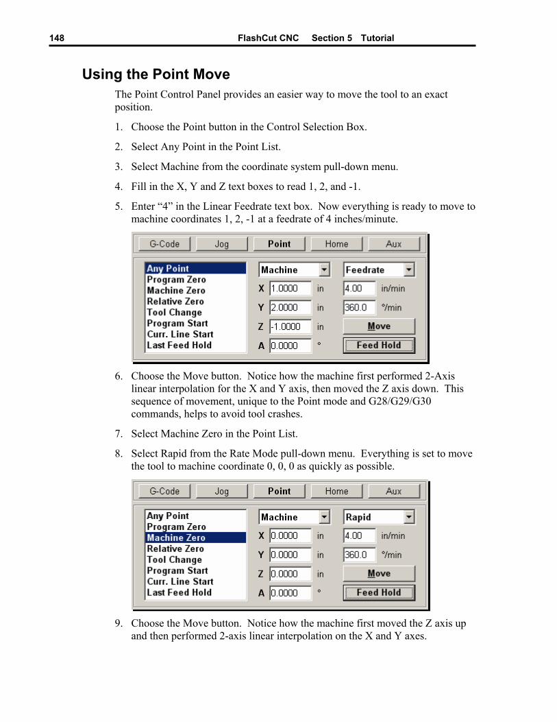
FlashCut CNC Section 5 Tutorial
148
Using the Point Move The Point Control Panel provides an easier way to move the tool to an exact position.
1. Choose the Point button in the Control Selection Box.
2. Select Any Point in the Point List.
3. Select Machine from the coordinate system pull-down menu.
4. Fill in the X, Y and Z text boxes to read 1, 2, and -1.
5. Enter “4” in the Linear Feedrate text box. Now everything is ready to move to machine coordinates 1, 2, -1 at a feedrate of 4 inches/minute.
6. Choose the Move button. Notice how the machine first performed 2-Axis
linear interpolation for the X and Y axis, then moved the Z axis down. This sequence of movement, unique to the Point mode and G28/G29/G30 commands, helps to avoid tool crashes.
7. Select Machine Zero in the Point List.
8. Select Rapid from the Rate Mode pull-down menu. Everything is set to move the tool to machine coordinate 0, 0, 0 as quickly as possible.
9. Choose the Move button. Notice how the machine first moved the Z axis up
and then performed 2-axis linear interpolation on the X and Y axes.
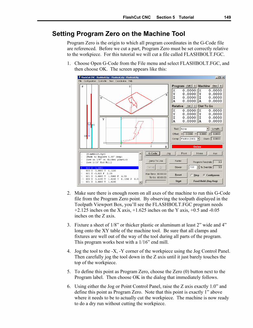
FlashCut CNC Section 5 Tutorial
149
Setting Program Zero on the Machine Tool Program Zero is the origin to which all program coordinates in the G-Code file are referenced. Before we cut a part, Program Zero must be set correctly relative to the workpiece. For this tutorial we will cut a file called FLASHBOLT.FGC.
1. Choose Open G-Code from the File menu and select FLASHBOLT.FGC, and then choose OK. The screen appears like this:
2. Make sure there is enough room on all axes of the machine to run this G-Code
file from the Program Zero point. By observing the toolpath displayed in the Toolpath Viewport Box, you’ll see the FLASHBOLT.FGC program needs +2.125 inches on the X axis, +1.625 inches on the Y axis, +0.5 and -0.05 inches on the Z axis.
3. Fixture a sheet of 1/8” or thicker plastic or aluminum at least 2” wide and 4” long onto the XY table of the machine tool. Be sure that all clamps and fixtures are well out of the way of the tool during all parts of the program. This program works best with a 1/16” end mill.
4. Jog the tool to the -X, -Y corner of the workpiece using the Jog Control Panel. Then carefully jog the tool down in the Z axis until it just barely touches the top of the workpiece.
5. To define this point as Program Zero, choose the Zero (0) button next to the Program label. Then choose OK in the dialog that immediately follows.
6. Using either the Jog or Point Control Panel, raise the Z axis exactly 1.0” and define this point as Program Zero. Note that this point is exactly 1” above where it needs to be to actually cut the workpiece. The machine is now ready to do a dry run without cutting the workpiece.
FlashCut CNC Section 5 Tutorial
150
Testing the Program on the Machine Tool It is always a good idea to do a dry run of the G-Code file both in offline and online modes before cutting a part. This lets you check for G-Code programming errors, spot interferences with fixtures, and so on.
1. Choose the G-Code button in the Control Selection Box.
2. Choose the Reset button to make sure the G-Code program is reset. Choose OK in the dialog that follows.
3. Take the Signal Generator offline by choosing Offline from the Controller menu.
4. Go into step mode by choosing the Step radio button.
5. Repeatedly choose the Start button, watching the screen to make sure the tool behaves properly.
6. Once you are satisfied the program will behave properly, re-establish communications with the Signal Generator by choosing Online from the Controller menu. A dialog will ask you if you want to revert to the coordinates used before going offline. Choose Yes.
7. Choose the Step radio button.
8. Choose the Start button. The machine should move the X and Y axes, and then stop.
9. Step through the entire program by choosing the Start button for every line of G-Code. If at any time you need to stop the tool, choose the Feed Hold button or hit any key on your keyboard. If you stop the tool in the middle of the program, you can start exactly where you left off by choosing the Start button. You may want to try this for practice.
Cutting the Part Assuming everything was fine in the previous step, we’re ready to cut a part.
1. Check to make sure the program coordinates are at 0, 0, 0. If not, go through the “Setting Program Zero on the Machine Tool” section above.
2. Go into jog mode and carefully move the tool down in the Z- direction to the part surface. This should be at the program coordinate 0, 0, -1.
3. Set this point as Program Zero by choosing the Zero (0) button next to the Program label and choosing Yes in the dialog that follows.
4. Now jog the tool 0.5” UP (in the Z+ direction). This places the tool in the correct starting position to begin cutting the workpiece.
5. Choose the G-Code button in the Control Selection Box.
6. Choose the Continuous radio button.
FlashCut CNC Section 5 Tutorial
151
7. Turn the machine tool spindle on and make sure everything is ready on the machine tool.
8. Choose the Start button and the machine tool will begin to cut out your first part. Always be on alert to choose the Feed Hold button or hit any key in case of emergency.
9. Congratulations! You’ve successfully cut your first part using FlashCut.
Exiting the Program To exit FlashCut, choose Exit from the File menu. This terminates communications with the Signal Generator and returns you back to Windows.
Turning off the Electronics Always turn off the Signal Generator and Motor Driver when they are not in use.

FlashCut CNC Section 6 Glossary
153
Section 6. Glossary
Backlash – The amount of motor movement that occurs without table movement when changing directions on an axis. A typical source for backlash is play between the screw and nut in the drive system.
Backlash Compensation – When an axis changes direction, a small turn of the motor to move the drive mechanism through any mechanical play, before resuming motion.
Baud Rate – The speed at which FlashCut communicates across the serial port with the Signal Generator. It’s measured in bits per second and is typically set at 38,400 – 115,200.
Continuous Contouring – An advanced feature that lets FlashCut run G-code files smoother and faster. Smooth transitions from one G-code line to the next allow high speed machining of complex 2D profiles and 3D surfaces. Also called “Look-Ahead” and “Constant Contouring.”
DRO Box – The area of the main screen that shows the current location of the machine tool. You can display one or all of the four coordinate systems in this box. ‘DRO’ is an acronym for Digital Readout.
DXF – Document eXchange Format. Defined by AutoDesk Inc. as a way to exchange design data between CAD, CAM, CAE and CNC programs.
Feedrate – The linear speed of the cutting tool relative to the workpiece. Defined in G-Code by the F parameter in inches/minute, millimeters/minute or degrees/minute.
Full-Step – Step mode where one step from the Signal Generator corresponds to one full step of a stepper motor.
G-Code – Standard programming language used to control CNC machines. G-Code Program – Program used to control the movement of the machine tool. G-Code is
an industry-standard machine tool programming language. Gear Ratio – The ratio of motor revolutions to drive screw revolutions due to gears, pulleys
or other devices. Half-Step – Step mode where two steps from the Signal Generator correspond to one full
step of a stepper motor. Home – Same as Machine Zero (see below). Included File – G-Code file containing subroutines that can be called from a main G-Code
file. The included file must be listed at the top of the main G-Code file. Jog – Method of manually controlling each axis of the machine tool. Limit Switches – Switches placed at the travel limits of each axis. When the machine tool
travels too far in either direction of any axis, a limit switch is tripped. The control system then stops the machine to prevent damage.
Machine Coordinates – The XYZA position of the tool relative to Machine Zero.
FlashCut CNC Section 6 Glossary
154
Machine Tool Envelope – The three dimensional box (plus optional 4th axis travel) defined
by the maximum travel in the X, Y, Z and A axes. Once the machine tool envelope is defined, the tool cannot move beyond it. You can disable the machine tool envelope by choosing the Clear button.
Machine Zero – The origin (X, Y, Z, A = 0, 0, 0, 0) of useful space within the machine tool envelope. Can either be defined manually or by using home switches.
Maximum Feedrate – The maximum rate at which a motor can reliably start and stop with ramping.
Modal – A type of command that stays in effect while FlashCut processes subsequent G-Code commands.
Motor Driver – The electronic box that converts step and direction signals from the Signal Generator into a sequence of amplified signals to drive a motor.
Motor Direction – The association between the actual direction an axis moves and the direction FlashCut intends it to move. If an axis moves in the wrong direction, this setting should be changed from positive to negative or vice-versa.
Motor Resolution – The number of full motor steps for one revolution of the motor. For example, a 1.8° Stepper motor has 200 full steps per revolution; a 0.9° Stepper Motor has 400 full steps per revolution, and so on.
Motor Step – The amount of motor movement associated with one electrical pulse to the stepper motor driver.
Offline – Mode in which FlashCut does not communicate with the Signal Generator. FlashCut displays all G-Code, Jog, and Point moves, but the machine tool does not move.
Online – Mode in which FlashCut communicates with the Signal Generator. In this mode, all G-Code, Jog and Point moves are executed by the machine tool.
Open Loop – A type of control system in which an actuator moves without sending motion information back to the controller. Most stepper motor systems are open loop due to their high reliability in performing step commands when used within their torque limits.
Program Coordinates – The XYZA position of the machine tool relative to Program Zero. Program Listing Box – The area of the main screen that displays the G-Code program
currently loaded into FlashCut. Program Zero – The zero point, or origin, to which all absolute coordinates in the G-Code
file are referenced. It is represented by a green dot in the Toolpath Viewport. Ramping – Smooth acceleration that allows a machine tool to reach high feedrates.
Ramping rates are measured in full steps/sec/sec. Relative Coordinates – The XYZA position of the machine tool relative to the point at
which the relative coordinates were zeroed. The relative coordinate system is general purpose and may be used for anything you choose (as long as it’s legal).
Resonant Speeds – Rotational speeds at which a stepper motor vibrates excessively. Often the motor will stall if run at these speeds. Resonant speeds depend on the size of the motor, the amount of loading, and the power of the motor driver. Typically, increasing the load and reducing motor driver current will reduce resonance.
Safety Interlock – Logic to prevent pairs of digital output lines from reaching an incompatible on-off state.
FlashCut CNC Section 6 Glossary
155
Screw Thread – The number of turns per unit length of travel of the helical drive screw for each axis.
Serial Port – A communications port on both the PC and the Signal Generator, used to exchange commands and other information.
Setup File – A file containing the CNC Setup Parameters for a machine tool. These files have an “STP” extension.
Signal Generator – The electronic box that converts computer commands into step and direction signals suitable for a stepper or digital servo motor driver. It also interprets input line signals and produces output signals to control various peripheral devices.
Start/Stop Feedrate – The maximum rate at which a motor can reliably start and stop without ramping.
Step Mode – The number of micro steps between each full motor step. Stepper Motor – A motor that moves a precise amount when given an electrical pulse.
Stepper motors typically have 200 full steps per revolution, or 1.8° per full step. Other popular stepper motors have 0.9° and 7.5° per step.
Tool Positioning Resolution – The amount of machine tool movement that results from one step pulse produced by the Signal Generator. For each axis, Tool Positioning Resolution (TPR) depends on 4 factors: Step Mode (SM), Gear Ratio (GR), Motor Resolution (MR), and Screw Thread (ST), where
TPR = 1 / (SM * GR * MR * ST)
Tooling File – A file containing the geometry information for up to 100 tools. These files have a “TLG” extension.
Toolpath – The path that a machine tool follows as FlashCut executes a G-Code program. Toolpath Viewport Box – The area of the main screen that graphically displays the toolpath
and updates the machine position in real time.