computer networks project 4 - rutgers university
TRANSCRIPT

Computer Networks Project 4
By Eric Wasserman and Ji Hoon Baik

Modifications to the Code, and the Flowcharts

UDP transmission is different from TCP transmission in that:
1. UDP transmission is unidirectional; information is sent only from the source to the destination, and the absence of feedback from the receiver prevents the sender from knowing whether the transmitted segments arrived successfully in order. In other words, retransmission is not supported.
2. UDP does not provide any means of reliability or congestion control. There’s no concept of acknowledgement and retransmission timer. What arrives is simply what the receiver gets.

Simulator.run()

Explanation for Simulator.run()
The only thing changed in the simulator.run() function is the addition of the UDP sender and receiver functions.
• An additional array is created to store the UDP segments.• When the TCP Sender is called, the UDP sender is called next.• When the router is called, the UDP segments along with the
TCP segments are sent to the function.• Lastly, when the TCP Receiver is called, the UDP receiver is
called next.

UDPSender.send()

Explanation for UDPSender.send()The UDPSender class has two variables, RTT and sendMode.• RTT keeps track of the number of iterations. • sendMode is 1 when the UDP Sender is sending packets
and is 0 when the UDP Sender is not sending packets (off mode).
The UDP Sender has two options:• If sendMode is 1 then it initializes the array of UDP
segments to the number of packets selected by the user.• If sendMode is 0 then it increases the RTT by 1.
In order to identify whether or not sendMode is 1 or 0, we use a modulus of two times sendMode duration.

Conditions for a UDP or TCP segment to be successfully relayed in a given transmission round:1. The segment is one of the first 7 segments being
transmitted.2. When the packet arrives in the router, either a UDP or a
TCP packet in the front head of the router buffer has just been completely relayed, so that an extra buffer space becomes available.
If one of these conditions is satisfied, no action is taken on the segment, and its respective array’s counter is incremented by 1.
If not, a segment loss occurs; the segment is nulled.
Routing Algorithm

Router.relay() part 1

Router.relay() part 2

Router.relay() explanationMost of the router has been changed to accommodate the incoming packets from the TCP sender and the UDP sender. The routing algorithm on page 7 was too difficult to implement, so the following simplified algorithm was used.
• When the UDP sender is in OFF mode (sendMode = 0), then the router will act normally.
• When the UDP sender is in ON mode (sendMode = 1), then the router will act as follows:
1. A random array of 1s and 0s is generated to designate the order of arrival of the TCP and UDP segments.
2. When the first seven packets are accepted based on the random array, then the next three packets are dropped.
3. Then, both a UDP packet and TCP packet is accepted to accommodate for the two sent packets from the router.
4. Packets are then dropped until the 20th packet, when another UDP packet and TCP packet is accepted.
5. This continues until there are no more UDP or TCP packets to drop or accept.

UDPReceiver.receive()

UDPReceiver.receive() Explanation
The UDP Receiver’s function is to just accept an array of UDP segments, count and display how many packets were successfully transmitted and then clear all of the packets in the UDP segment array.

Analysis of Simulation Results

TCP Tahoe Transmission without Concurrent UDP Transmission

TCP Transmission with Concurrent UDP Transmission, 5 UDP Packets/RTT, ON and OFF cycles 4 RTTS
Effective window at the end of the slow-start phase is smaller.
Shorter Fast-Retransmit Time
Frequency of congestion avoidance phases increases. 6
2
5
43
1

Effects of UDP Transmission on TCP Transmission
• Without any concurrent UDP transmission, the TCP sender inflates the congestion window to a larger value and tries to transmit more TCP packets per RTT during the initial slow-start phase. In addition, the sender has a longer fast-retransmit period, and enters congestion avoidance at a much later time instant.
• With UDP transmission, the effective window of the TCP sender at the end of the slow-start phase is reduced by approximately 50 %. The sender enters congestion avoidance at a much earlier time. The repeated congestion avoidance periods that follow the fast-retransmit period have varying durations and are more irregular than those of the sender without UDP transmission. This is because the arrival of UDP and TCP packets in the router buffer was randomized.

Explanation for TCP Transmission with Concurrent UDP Transmission Graph
If you compare the TCP transmission parameters with and without concurrent UDP transmission there is one main difference. The graph with concurrent UDP transmission only reaches a congestion window of 12 compared to a congestion window of 15 for the graph without competing UDP. Then the graph with competing UDP enters congestion avoidance phase much quicker than the other graph.
Overall, the graph with competing UDP has a smaller congestion window throughout the run but it enters congestion avoidance phase much quicker. This is because the UDP sender floods the router with packets preventing the TCP sender from inflating its congestion window. This proves to be more efficient because the TCP sender won’t have to wait to retransmit as many packets as it would have without the competing UDP sender.

1 MB Data Transmission Times of the TCP sender with/without Concurrent UDP Transmission,
• With UDP Transmission—5 UDP Packets/RTT, and 4 RTTs ON and 4 RTTs OFF—approximately 694 iterations were needed (an average value of results from 10 trials).
• Without UDP transmission, 451 iterations were required.
• The performance of the TCP sender was degraded by 53.9 % when it shared the router resources with a UDP sender.

1 MB Data Transmission Time (# of Iterations)vs. Number of UDP Packets Sent/RTT

Table of Data Used for the Graph
1 MB TCP Transmission Time (# of Iterations)
# of UDP Packets/RTT Trial 1 Trial 2 Trial 3 Trial 4 Trial 5 Average
1 448 448 448 448 448 448
2 629 641 621 641 654 637.2
3 542 449 571 471 633 533.2
4 711 688 677 611 723 682
5 626 760 730 717 729 712.4
6 728 698 721 787 741 735
7 712 725 732 744 809 744.4
8 749 743 754 758 683 737.4
9 732 739 743 767 705 737.2
10 714 685 705 767 680 710.2

Explanation for the Variations in 1 MB TCP Data Transmission Time with UDP Packets Sent/RTT
The curve shows an exponential relationship that can be approximately described according to:
The UDP transmission steadily increases the 1 MB TCP data transmission time until 5 UDP packets per cycle. Beyond this point, the effect of UDP transmission stabilizes; increasing the number of UDP packets does not translate to increasing the transmission time.

ON 4OFF 4
ON 5OFF 1
ON 1OFF 0
ON 1OFF 1
ON 2OFF 1
ON 2OFF 2
ON 3OFF 1
ON 3OFF 2
ON 3OFF 3
ON 4OFF 1
ON 4OFF 2
ON 4OFF 3
1 MB Data Transmission Time ( # of Iterations) vs. UDP ON and OFF Cycles

Table of Data Used for the Graph
1 MB TCP Transmission Time (# of Iterations)
UDP ON Cycles UDP OFF Cycles Trial 1 Trial 2 Trial 3 Trial 4 Trial 5 Average
1 0 451 451 451 451 451 451
1 1 633 577 597 579 685 614.2
2 1 756 702 738 711 705 722.4
2 2 795 759 747 712 763 755.2
3 1 723 677 708 763 744 723
3 2 734 725 827 750 723 751.8
3 3 773 698 738 734 765 741.6
4 1 725 738 715 688 740 721.2
4 2 758 795 732 760 795 768
4 3 748 768 783 752 730 756.2
4 4 701 696 667 724 720 701.6
5 1 772 740 724 729 704 733.8

Explanation for the Variations in 1 MB TCP Data Transmission Time with UDP ON and OFF cycles
The graph appears to have a clear pattern.
For a given UDP ON cycle, the transmission time steadily decreases with the UDP OFF cycle, except when the OFF cycle goes from 1 to 2 RTTs. For example, for the ON cycle of 3 RTTs, the transmission time increases as the OFF cycle varies from 1 to 2 RTTs; then, it decreases from 2 to 3 RTTs. Similarly, for the ON cycle of 4 RTTs, the transmission time increases as the OFF cycle varies from 1 to 2 RTTs; then, it decreases from 2 to 4 RTTs. Although not shown on the graph, the same pattern could be observed for ON cycles higher than 4 RTTs.
However, when the ON cycle is larger than 2, the effect of UDP transmission stabilizes; the transmission time stops increasing with the ON cycle, regardless of the OFF cycle. For example, the transmission time for an ON cycle of 10 RTTs and 20 RTTs (not shown on the graph), the transmission time remain in the 700 iterations range.

TCP/UDP Sender Utilization
UDP sender utilization was calculated by taking the ratio of the number of successfully transmitted UDP packets to the number of UDP packets that could be transmitted, for a given UDP packets/RTT and UDP ON and OFF cycles setting, had the router not caused any congestion.

Variations in TCP/UDP Sender Utilization with the Number of UDP Packets Sent/RTT
UDP ON = 4 RTTsUDP OFF = 4 RTTsOver 1000 Iterations

Explanation for Variations in TCP/UDP Sender Utilization with the Number of UDP Packets Sent/RTT Graph
The graph on the previous slide shows how the sender utilization for TCP and UDP change when more UDP packets are sent in each RTT. The most important thing to see in the graph is that UDP sender utilization decreases almost linearly with the number of packets it sends while the TCP sender utilization stays almost constant. This mainly has to do with the difference between UDP and TCP. TCP sends packets based on its effective window and congestion window so it will not send packets when it know that there are packets that have not reached the receiver. UDP, however, just sends packets arbitrarily, so the more packets that are sent, the more packets that will just be dropped when the router buffer fills up.
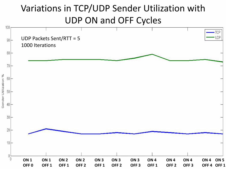
Variations in TCP/UDP Sender Utilization with UDP ON and OFF Cycles
UDP Packets Sent/RTT = 51000 Iterations
ON 1OFF 0
ON 1OFF 1
ON 2OFF 1
ON 2OFF 2
ON 3OFF 1
ON 3OFF 2
ON 3OFF 3
ON 4OFF 1
ON 4OFF 2
ON 4OFF 3
ON 4OFF 4
ON 5OFF 1

Explanation for Variations in TCP/UDP Sender Utilization with UDP ON and OFF Cycles Graph
The graph on the previous page shows that when the UDP Sender’s ON / OFF cycles change, the sender utilizations for the TCP sender and UDP sender remain almost constant. This could be due to the fact that when the UDP senders ON / OFF cycles changes, the total incoming packets sent to the router in a given RTT do not change very much. The UDP sender’s utilization remains constant because it is still sending the same amount of packets when it is in on mode. The duration of the on or off mode has little to do with how many packets successfully reach the receiver. The TCP sender has better utilization when the UDP sender is in off mode, but over the entire run, the on and off modes average out so that it matters very little the duration of the on or off modes. Even when there is a longer on mode than off mode for the UDP sender, the utilization of the TCP sender still remains about the same, even though we would expect it to have a lower utilization.