computer networks - nc state university · self-orienting wireless multimedia sensor networks for...
TRANSCRIPT

Computer Networks 52 (2008) 2558–2567
Contents lists available at ScienceDirect
Computer Networks
journal homepage: www.elsevier .com/locate /comnet
Self-orienting wireless multimedia sensor networksfor occlusion-free viewpoints
Nurcan Tezcan *, Wenye WangDepartment of Electrical and Computer Engineering, North Carolina State University, Raleigh, NC 27606, USA
a r t i c l e i n f o
Available online 14 June 2008
Keywords:Multimedia coverageMultimedia sensor networkVisible field of viewOcclusionSelf-orientationDistributed algorithm
1389-1286/$ - see front matter � 2008 Elsevier B.Vdoi:10.1016/j.comnet.2008.05.014
* Corresponding author. Tel.: +1 862 368 5591.E-mail addresses: [email protected] (N. Tezcan
(W. Wang).
a b s t r a c t
Wireless multimedia sensor networks (WMSN) are formations of a large number of com-pact form-factor computing devices that can capture multimedia content, such as videoand audio, and communicate them over wireless channels. The efficiency of a WMSN heav-ily depends on the correct orientation (i.e., view) of its individual sensory units in the field.In this paper, we study the problem of self-orientation in WMSN, that is finding the mostbeneficial orientation for all multimedia sensors to maximize multimedia coverage. Wepropose a new algorithm to determine a node’s multimedia coverage and find the sensororientation that minimizes the negative effect of occlusions and overlapping regions inthe sensing field. Our approach enables multimedia sensor nodes to compute their direc-tional coverage leading to an efficient and self-configurable sensor orientation calculation.By using simulations, we show that the occlusion-free viewpoint approach increases themultimedia coverage significantly. The self-orientation methodology is designed in theform of a distributed algorithm, making it a suitable candidate for deployment in practicalsystems.
� 2008 Elsevier B.V. All rights reserved.
1. Introduction
As we manufacture more sophisticated sensing elec-tronics cheaper every day, the nature of the informationto be hauled by wireless sensor networks (WSNs) change.We are now able to capture audio-visual information fromthe environment using low-cost, low-resolution camerasembedded in sensor nodes. The need for using such multi-media sensors is usually driven by the necessity of provid-ing comprehensive information pertaining to a specificregion of interest. To be able to support the demand formonitoring, we focus on wireless multimedia sensor nodeswith directional sensing views. Performance of directionalsensing is very much dependent on the obstacles presentin the environment. Therefore, finding the most favorableorientation for the multimedia sensors is an importantand challenging problem. For example, deploying a large
. All rights reserved.
number of low-resolution image sensors is recently shownto be a good alternative to having a single high-resolutioncamera [1]. Distributed methods for camera sensornetworks also show gains from using a large number oflow-power image sensors [1,2]. In such WMSNs, inherentdisadvantages due to physical obstacles in an environment(e.g., trees, buildings, etc.) can be turned into a multimo-dality advantage, with the flexibility to adjust orientationsof the multimedia sensors attached to the wireless nodes.
There have been several works on vision planningwhich take the object geometry information as an inputfrom a database, as well as modifications of the cameraand the lens to determine camera poses and settings [3].Therefore, orientation of multimedia sensors can be per-formed on site once the multimedia sensors have been de-ployed. However, such methods need an accurate fieldinformation database before deployment and are mostlyapplied to a small number of multimedia devices. Due toexternal effects or application-specific queries in WMSNs,multimedia nodes may need to change/re-orient their pose(direction of sensory unit) over time. In WMSNs, nodes
N. Tezcan, W. Wang / Computer Networks 52 (2008) 2558–2567 2559
may fail due to battery outage or external effects whichshould be handled by a dynamic update of the poses whichcan be performed via local information exchange amongsensors.
In this paper, we present a new distributed method tofind the most beneficial orientations for the sensors usedin a WMSN. We specifically consider (i) minimizing the ef-fects of occlusion in the environment and (ii) improvingthe cumulative quality of the information sensed fromthe region of interest. Let us consider a WMSN with a largenumber of scattered nodes, each having neighbors withwhich it can communicate directly. Using a distributedmethod outlined in this paper, each node can discover itsneighbors and examine possible overlapping sensing re-gions as well as the obstacles in the environment. In ourscheme, each sensor node determines the most beneficialorientation for its multimedia sensor so that the entire im-age of a field can be constructed using low-resolutionsnapshots from multiple sensors. Our approach enablesmultimedia sensor nodes to monitor their coverage perfor-mance, provisioning self-configurable sensor orientationsin an efficient way.
The proposed algorithm also decreases the obstacles’detrimental effect on the quality of the sensed informationwhile maximizing total covered area. As discussed in [4,5],WMSNs have stringent constraints of limited communica-tion bandwidth, processing capability, and power supply todeliver multimedia context. It is crucial to capture themost recent occlusion-free multimedia context from theenvironment. This helps newly designed WMSN protocols[5] delivering efficient multimedia context with the lim-ited bandwidth resource.
In this context, we summarized the contributions of thispaper as follows: (i) the proposed algorithm is fully distrib-uted using local information: thus communication over-head is incurred only between neighboring nodes;(ii) with the flexibility to adjust orientations of the multi-media sensors, multimedia sensor nodes update the orien-tation of multimedia sensors on the fly to increase themultimedia coverage significantly, (iii) overlapped and oc-cluded regions in the sensing field can be decreased by col-lecting the current pose of neighboring nodes and (iv)coverage is increased even for sparse networks by usingself-orientation instead of random orientations, for arbi-trary obstacles in the sensor field.
The remainder of the paper is organized as follows. InSection 2, we review the existing work on sensing coverageand multimedia coverage in WMSNs. We summarize thechallenges on multimedia converge and define the multi-media coverage problem in Section 3, and propose a newdistributed algorithm for multimedia coverage calculationin Section 4. Performance evaluation is discussed in Sec-tions 5 and 6 concludes the paper.
2. Related work
Maintaining and maximizing the coverage of an areahave been studied in great depth in the fields of multime-dia, robotics and wireless sensor networking. From theperspective of sensor networking, considerable work is
present for the omnidirectional coverage problem [6–9]that aims to cover a plane by arranging circles on the plane.However, the proposed solutions for omnidirectional cov-erage cannot be used for the coverage of bidirectionaland field-of-view sensors such as low-resolution videocameras. A common limitation of these existing protocols[6,10,11] is that the collected information on phenomena(e.g., temperature, concentration of a substance, lightintensity, pressure, humidity, etc.) are assumed to comefrom an omnidirectional sensing. However, multimediasensors, (i.e., low-resolution cameras, microphones, etc.)have the unique feature of capturing direction-sensitivemultimedia content. Especially, video sensors can onlycapture useful images when there is line of sight betweenthe event and the sensor [12]. Hence, coverage modelsdeveloped for traditional wireless sensor networks arenot sufficient for deployment planning of a multimediasensor network.
In [13], a preliminary investigation of the coverageproblem for video sensor networks is addressed. The con-cept of sensing range is replaced with the camera’s fieldof view, which is the maximum volume visible from thecamera when sensors are placed on the floor. All cameranodes are assumed to be situated on a plane (at the ceilingof the monitored room), and they shoot the images of thescene from a parallel plane. Such a ceiling placement, how-ever, may only fit specific indoor applications. Then,authors proposed a routing scheme for the video sensorsbased on cameras’ field of view metrics. Video sensorsare directed to the floor, and coverage is determined bydisk shaped scenes on the floor, without considering ef-fects of any occlusions. On the other hand, a wide rangeof multimedia applications require outdoor placement ofmultimedia sensors. Several projects on habitat monitoringuse acoustic and video feeds from the multimedia sensorsscattered in the environment. Similarly, a large number ofvideo sensors are already used by oceanographers to ob-serve sandbars via image processing techniques.
In addition, triangular view regions are used for com-puting multimedia coverage of sensor networks in [14].The major goal of this work is to find the minimum ob-served distance to any multimedia sensor that any targettraveling through the field must have, even if the targetoptimally tries to avoid the sensors. Sensors are assumedto have a isosceles triangular coverage (field of view)placed on a square field. Using mathematical modeling,worst-case breach coverage is calculated using a polyno-mial time algorithm. One limitation of this work is the lackof occlusions which is the most common problem of multi-media sensors. Any obstacle in the Field of View (FoV) re-gion result in occlusion which should be considered whilecalculating the worst-case breach coverage. Second, theproposed algorithm determines the closest observable dis-tance to a sensor that any target must have for a given adeployment. Differing from this study, our goal is to deter-mine and then increase the multimedia coverage of eachindividual sensor and in total by designing a local algo-rithm to self-orient the pose of the sensors.
In terms of occlusion effect, [1] has several investiga-tions for wireless camera networks. The paper shows thatdeploying a large number of low-resolution image sensors

2560 N. Tezcan, W. Wang / Computer Networks 52 (2008) 2558–2567
is a better alternative compared to a single high-resolutioncamera in highly-occluded environments. Therefore, dis-tributed methods for camera sensor networks have gainsover using a large number of low-power image sensors[1,2]. They observed that a collection of low resolution(short sensing range) sensors outperforms a single sensorwith equivalent coverage as the degree of occlusion inthe environment increases [1].
On the other hand, the geometric variations of the clas-sic camera placement problem are also related to our prob-lem. However, none of these variations in the literatureaddressed cameras as individual multimedia sensor nodeswhich can communicate to each other. In [15], an in-depththeoretical analysis of the problem is shown to maximizecamera coverage of an area, where the camera fields ofview do not overlap. In [16], the art gallery framework isfurther refined by introducing a resolution quality metric.In addition, Isler et al. extended the formulation of theminimum guard coverage art gallery problem to incorpo-rate the minimum-set cover problem. They derived re-duced upper bounds for two cases of exterior visibilityfor two- and three-dimensions [17]. In the field of robotics,a system was developed to perform dynamic sensor plan-ning for a camera mounted on a moving robotic arm in or-der to compute optimal viewpoints for a preplannedrobotic grasping task. In [3], a planning method was pre-sented to determine optimal camera placement giventask-specific observational requirements such as field ofview, visibility, and depth of field. Our research differsfrom the existing works since it calculates the optimal ori-entation of sensor nodes using local information only afterthe initial deployment. In addition, our method considers alarge number of sensor nodes with multimedia sensorshaving much lower resolution than the multimedia devicesdiscussed in [3,17].
3. Multimedia coverage and self-orientation
As audio-visual sensors take their places on wirelessnodes, the omnidirectional sensing assumption losesground significantly since a typical audio or video sensorhas a sectoral perception and is effected heavily by sur-rounding obstacles [12]. Therefore, we envision that sens-ing coverage planning for the wireless multimedia sensornetworks (WMSN) will be different from what first-gener-ation sensor networks used. Multimedia sensors, such ascameras, are powerful multidimensional sensors that cancapture a directional view, usually called Field of View(FoV). The most commonly used low-resolution cameramodule is equipped with a lens providing a 45� FoV [3].For example, the human eye, without any rolling move-ment, can only see objects lying inside a cone having a25� half-angle [3]. To obtain a much wider view of the sur-roundings, fisheye lenses with a FoV of 150� FoV have beendeveloped [2]. In this work, we assume sensors nodes havefixed lenses providing a field of view with angle H, and theycan only pan to adjust their FoV as shown in Fig. 1. We usethe term ‘‘camera sensors” for simplicity to represent wire-less multimedia sensors including video and audio sensorshaving a directional view.
Multimedia nodes are densely deployed, providing de-tailed visual and audio information from multiple disparateviewpoints. Low resolution sensors can be used for manyWMSN applications such as environmental monitoring,and health care. A sensor resolution of 128 � 128 is usuallyenough for typical applications, whereby 320 � 240 mightbe required for some applications requiring object recogni-tion [18]. Each camera node is responsible for extractingnecessary data out of the captured video stream and send-ing it to a base station. A multimedia sensor network withN sensors is represented by S ¼ fs1; s2; . . . ; sNg, which canbe deployed in a polygonal sensing field, denoted by A.We also assume that each node is equipped to learn its loca-tion information via any lightweight localization techniquefor wireless sensor networks [19].
Let us denote the distance between si and sj by dði; jÞ,
where dði; jÞ ¼ jffiffiffiffiffiffiffiffiffiffiffiffiffiffiffiffiffiffiffiffiffiffiffiffiffiffiffiffiffiffiffiffiffiffiffiffiffiffiffiffiffiffiffiffiðxi � xjÞ2 þ ðyi � yjÞ
2q
j. If dði; jÞ < 2Rs,where Rs denotes multimedia sensing range, sensors si
and sj are FoV neighbors that share sensing area in common.These sensors use FoV neighbor information to computenon-overlapping viewpoints. A communication link existsbetween sensor si and sensor sj if a single-hop transmissionfrom si to sj and sj to si can be performed successfully. Sen-sors si and sj are transmission neighbors; if there is a sym-metric link between them. Each sensor si is associatedwith quad (xi; yi;Ti;CiÞ, where Ti represents transmissionneighbors, and Ci represents the set of FoV neighbors.
A sensor is called self-orienting, if it is capable of adjust-ing its pose at the point of deployment (low-cost multime-dia sensors [20] that are capable of panning). In thiscontext, some definitions that will be used in the rest ofthe paper are as follows:
Definition 1. Field of View (FoV): The term field of viewrefers to the directional view of a multimedia sensor and isassumed to be an isosceles triangle (two-dimensionalapproximation) as shown in Fig. 2. A field of view of asensor si is denoted by KHi
i , where the parameter Hi is thevertex angle of the isosceles triangle.
Definition 1.1. Visible FoV (vFoV): Visible FoV, denotedby vKHi
i , is a FoV of a sensor node si which is visible tothe sensor itself, i.e., has not been blocked by any obstruc-tion within FoV, 8 obsj in A, if obsj \KHi
i ¼ ;, thenKHi
i ) vKHii , where obsj is an obstacle in the sensing field.
Definition 1.2. Occluded FoV (oFoV): The contrary ofvFoV is the occluded FoV such that, 8obsj in A, ifobsj \KHi
i 6¼ ;, then KHii ) oKHi
i .
Definition 1.3. Overlapping FoV (xFoV): The visible FoV isreferred to as overlapping FoV if it intersects with any of theneighboring sensor’s visible FoV, 8sj 2 Ci, if there existsvKHi
i \ vKHj
j 6¼ ;, then KHii ) xKHi
i .
Definition 2. FoV disk: The FoV disk associated with asensor defines the set of all possible FoVs. For simplicity,we assume that the orientation of all sensors can be any-where in between [00,3600]; thus, FoV disk is a circulardisk having a radius of Rs, i.e., the maximum distance tocapture with a given resolution.

Fig. 1. Two dimensional representation of a wireless multimedia sensor network having four low-resolution sensors. In the left figure, the nodes’orientation is randomly determined. The right one illustrates the same area with slight changes in orientation. Gray areas are the regions visible by thesensors.
Fig. 2. Illustration of two dimensional field of view (FoV) of a multimedia sensor node, where a is the vertical angle to the boundary edge of FoV showingthe current orientation, H is the FoV vertex angle, and Rs is the maximum multimedia sensing range.
N. Tezcan, W. Wang / Computer Networks 52 (2008) 2558–2567 2561
4. A distributed solution to multimedia sensors self-orientation problem
Our solution is designed in the form of a distributedalgorithm. The main reason behind the distributed ap-proach is making our algorithm a suitable candidate fordeployment in practical systems. Centralized orientationof WMSN systems may not clearly scale since WMSNsare usually composed of a large number multimedia nodes.In addition, we may need to update the orientations whichwould be more costly in a centralized approach comparedto that of a distributed approach.
In the rest of this section, we will explain the details ofthe self-orientation algorithm that has three major phases:(i) initial messaging; (ii) distributed FoV detection; and(iii) self-orientation algorithm as shown in Fig. 3. Eachphase has specific tasks and uses a set of messages. Next,we walk through each phase in detail.
4.1. Initial messaging phase
Sensor nodes exchange messages between neighbors tocollect the neighborhood information. All sensors broad-cast a HELLO_MSG indicating their unique sensor IDs andtheir location coordinates. We assume that stationary sen-sors having identical FoV ranges are located in the sensing
Fig. 3. Three major steps in self-orie
field. Finally, each sensor processes the HELLO_MSG andlists overlapping FoV neighbors. The initial messagingphase ensures that every sensor is aware of its neighborsand their locations.
4.2. Distributed FoV detection
Distributed FoV detection uses three consecutive teststo detect sensor’s maximum visible FoVs. The first test,namely perimeter test, checks the existence of a visibleFoV within [00,3600]. If a sensor fails to find a visible FoVduring the perimeter-test, it moves to the second testcalled neighbor-distance test which examines the distanceto FoV neighbors. Finally, the third test, called obstacle-dis-tance test, is performed if the sensor fails the neighbor-dis-tance test. It compares the occluded FoVs to find the largestvisible FoV. Here, we explain these three tests as follows:
4.2.1. Perimeter testIn perimeter-test, each sensor scans its FoV disk perime-
ter to determine whether a visible FoV (which cannot becaptured by any other FoV neighbor) exists in its FoV disk.The reason is that FoV disk perimeter can effectively showocclusions and possible overlapping regions. The intersec-tion points of any tangent touching an existing obstacle onthe perimeter can be used to determine the size of the
ntation of multimedia sensors.

Fig. 5. Pseudo code of perimeter test.
Fig. 6. Pseudo code of neighbor-distance test.
2562 N. Tezcan, W. Wang / Computer Networks 52 (2008) 2558–2567
occlusion. For example in Fig. 4, the FoV disk of sensor s1 isillustrated. There are two obstacles inside its FoV diskwhich are close enough to s1 so that an occlusion may re-sult. The intersections of the tangents on the perimeter areshown with points F and G for the first obstacle (obs1); Hand A for the second obstacle (obs2). Therefore, a sensorsi can determine that if there exists a KHi
i whereKHi
i \K\FOGi ¼ 0 or KHi
i \K\HOAi ¼ 0 then KHi
i is a visibleFoV and we refer to arcs cFG (counter clock-wise) and cHAas occluded arcs on the FoV disk of s1 (see Figs. 5 and 6).
The perimeter-test not only finds the visible FoV butalso helps to determine non-overlapping FoVs in a FoVdisk. In this step, sensors do not know the orientations oftheir FoV neighbors. However, they can determine possibleoverlapping FoVs inside their FoV disks. Similar to oc-cluded arcs, each sensor finds possible overlapping arcs onits perimeter using the location information received fromits neighbors. To do this, the intersection points of the arcsare determined and the perimeter is scanned as illustratedin Fig. 4. For example, sensor s1 has an overlapping arc cBDand cCE.
By examining each FoV neighbor and obstacles, a sensordecides whether occluded and overlapped arcs enclose itsperimeter from 0� to 360� [21]. If there is a vKHi
i withHi P H such that xKHi
i does not exist, we say that the‘‘perimeter-test” is passed. This means that the sensorhas a visible FoV which has not been captured by any othersensor in any orientation. Since our goal is to maximize thevisible FoV in the total sensing region, sensors which passthe perimeter-test will adjust their pose. On the otherhand, sensors that do not pass the perimeter-test continuethe FoV detection with the neighbor-distance test, whichwill be explained in the following subsection.
Fig. 4. An example showing the perimeter test for sensor s1.
4.2.2. Neighbor-distance testPassing the parameter test implies that a sensor has a
visible FoV, which cannot be covered by its neighbors inany orientation (non-overlapped in any case). In the neigh-bor-distance test, however, we examine whether a sensorhas visible FoV which might be overlapped. If a sensorhas a vKHi
i with an angle Hi P H in its perimeter, it is as-sumed to pass the neighbor-distance test, otherwise itmoves to obstacle-distance test. Sensors that pass theneighbor-distance test then find the largest visible FoVbased on neighbor’s distances.
Even though the final orientations of the neighbors arenot known, FoV neighbors might have overlapping FoVs. Inthis case, sensors need to find the smallest overlapping FoVby scanning visible arcs and calculating the distances be-tween each neighbor. A closer neighbor implies a largeroverlapping FoV. In Fig. 7, the FoV disk of sensor s1 andits neighbors are shown. Since perimeter of s1 is enclosedby an occluded arc cFH and overlapping arcs cFA, cBC , cDE,and cGA, sensor s1 fails the perimeter-test. However, itpasses the neighbor-distance test, since arc cHF is visiblewhich is greater than H, the FoV angle of the camera sen-sors which is assumed to be fixed. Among the neighbors s2,s3, s4 and s5, sensor s2 has the largest distance to s1, de-noted by dð1;2Þ, indicating smallest possible overlappingFoV, shown as dark shaded areas inside the FoV disk.
4.2.3. Obstacle-distance testFinally in the obstacle-distance test, sensors with no
vFoV are examined. Fig. 8 shows an example sensor s1 sur-rounded by four obstacles. Since there is no visible arc in

Fig. 7. An example showing the neighbor-distance test for sensor s1.
Fig. 8. An example showing the obstacle-distance test condition forsensor s1.
Fig. 9. Pseudo code of obstacle-distance test.
N. Tezcan, W. Wang / Computer Networks 52 (2008) 2558–2567 2563
the perimeter greater than H, the final orientation of sen-sor s1 will not have a visible FoV. However, by findingthe distances between the obstacles and the sensor node,the occluded FoV can be minimized by keeping the visibleFoV maximized. Similar to the neighbor-test, a closerobstacle means a larger occluded FoV. In such conditions,
a sensor scans the perimeter in order to find the most ben-eficial arc H, to maximize the visible FoV (see Figs. 9, 10).
Note that the perimeter of the FoV disk may not befully-occluded or fully-overlapped. For example, In Fig. 8,arc cFA and cDE are visible and non-overlapped arcs, butsmaller than H. In such cases, these small segments canbe included in the FoV. In Fig. 8, the FoV of sensor s1 isshown as a shaded region which includes the arc cCD andoccluded regions with larger distances from obstacles.
Note that, in our algorithm, multimedia sensors can up-date their neighbor lists and orientations periodically bytaking the advantage of local information exchange. Thus,all tests are performed using up-to-date FoV neighborsand their orientation decisions.
4.3. Distributed FoV detection-based heuristic algorithm forself-orientation
In this section, we present a heuristic algorithm to ob-tain the most beneficial pose of the sensors for the multi-media sensors self-orientation problem. Under the 360�pan-capability assumption, multimedia sensors will deter-mine their pose for self-orienting by using their local one-hop neighborhood information. The dimensions and thelocations of the obstacles are assumed to be known by sen-sors before self-orientation. We do not consider the multi-media sensors as obstacles with respect to the othermultimedia sensors due to their small size.
Based on the test for distributed FoV detection pre-sented in Section 4.2, we propose a heuristic algorithm de-scribed as follows:
Step 1: Sensors send the HELLO_MSG that indicates thelocation of the sensors. For self-orientation, sensors mustbuild a list of FoV neighbors that are close enough to havean overlapping FoV. A received HELLO_MSG is then used toupdate the neighbor lists. Note that, we assume that themaximum sensing range, Rs, is equal to or smaller thanthe transmission range of the multimedia sensors.
Step 2 and Step 3: After exchanging the HELLO_MSG, eachsensor has an up-to-date FoV neighbor list with their loca-tions and apriori-known obstacle locations. The next stepis performing the perimeter test. As we explained in Sec-tion 4.2.1, perimeter test checks if a sensor si has a visibleFoV, vKHi
i , which cannot be captured by any other FoVneighbor in a FoV disk. Thus, when the perimeter test ispassed, the sensor si can self-orient to vKHi
i and finalizethe self-orienting algorithm. On the other hand, sensorsfailing the perimeter test will continue the algorithm withthe neighbor-distance test.
In particular, the perimeter test shows the existence ofat least one vFoV that cannot be observed by others in anyorientation. However, there may be more than than one

Fig. 10. The general approach of the self-orientation algorithm.
2564 N. Tezcan, W. Wang / Computer Networks 52 (2008) 2558–2567
visible FoVs that result in passing the perimeter test. Thensensors change their pose to the most beneficial vFoV.Here, the term beneficial corresponds to having smallestpanning angle to a self-orienting multimedia sensor. There-fore, a sensor selects a vKHi
i with a vertical angle of ai to theboundary (as shown in Fig. 2) such that jai � a0j is thesmallest among all possible vFoVs, where a0 is the currentvertical angle. After changing the pose, a sensor shouldadvertise its decision to all its neighbors with a PO-
SE_ADV_MSG and finalize the self-orienting procedure.In Step 3, sensors that have failed the perimeter test up-
date their neighbor list based on the POSE_ADV_MSGs theyreceived. If a sensor receives a POSE_ADV_MSG from a FoVneighbor, it updates its neighbor list by adding the poseof its neighbor for the next steps. Step 4 and Step 5: In Step4, sensors invoke the neighbor-distance test to find a occlu-sion-free FoV. By passing the neighbor distance test, a sen-sor determines the existence of a visible FoV in the FoVdisk. From the visible FoVs, it selects the pose toward theFoV neighbor sd with maximum distance, using the candi-date pose selection procedure in Step 5 and sends its candi-date pose by a CANDIDATE_ACK_MSG to the neighbor sd.This message indicates the candidate pose of the sensorto its neighbors.
Since sensor nodes perform the self-orienting simulta-neously, sensors then receive a CANDIDATE_ACK_MSG fromtheir neighbors who have passed the neighbor-distancetest, thus replying with a ACK_POSE_MSG if no xFoV occurs.Whenever a sensor receives ACK_POSE_MSG, it indicatesthat the sensor can select this pose safely and finalize the
self-orienting procedure. Otherwise, a sensor should repeatthe Step 5 with the second minimum distance neighbor.Step 6: Finally, sensors that failed the perimeter and neigh-bor distance test perform the last test, the obstacle-dis-tance test. Since they have failed the previous tests, novisible FoV exists in their FoV disk. Thus, in Step 6, sensorswill select an occluded FoV with maximum coverage whichis the pose toward the obstacle with maximum distancesimilar to the neighbor-distance test. If there is a visibleFoV with an angle smaller than H, the final pose will be se-lected from the small vFoV including the occluded FoV tomaximize the visible region that the sensor will capture.
The self-orienting algorithm uses OðNÞ messages whichtakes OðNÞ time. Every node sends a HELLO_MSG and PO-
SE_ADV_MSG once. And sensors which execute the neigh-bor-distance test exchange one CANDIDATE_POSE_MSGand one ACK_POSE_MSG. Thus, the total number of thesemessages is OðNÞ.
At the end of this algorithm, each sensor selects its poseand self-orients to maximize total visible FoVs over thesensing field A. One may argue that, the system may re-quire overlap in the coverage of cameras in some applica-tions, e.g., mobile tracking using camera sensor networks.Overlapping coverage can help to localize objects [22],especially moving objects. In such applications, sensorsshould self-orient for occlusion-free but overlapping FoVswhich can be achieved by simple modifications in our algo-rithm. Each sensor calculates the intersection points of A0
and its FoV disk such that in the perimeter test, any visiblearc overlapped with A0 is selected without considering the

Fig. 12. Multimedia coverage ratios.
N. Tezcan, W. Wang / Computer Networks 52 (2008) 2558–2567 2565
neighboring overlapped regions. In this way, our algorithmcannot only be used to maximize the visible coverage butalso serve for any application where overlapping FoV isnecessary. Next, we show our extensive simulation resultsfor different scenarios.
5. Performance evaluation
5.1. Simulation settings
We have used Ns-2 simulator [23] for the performanceevaluation of our algorithms. Simulations have been per-formed for randomly placed sensor nodes in a rectangulartwo-dimensional terrain. All sensor nodes have been con-figured with an FoV vertex angle H ¼ 60�, and an Rs of30 m. Communication between two sensors are assumedto be possible (i.e., an edge exists between two sensorsnodes in the connectivity graph), if the distance betweenthe transmitter and receiver is no more than 60 m. A sens-ing field spanning an area of 250 � 250 m2 has been usedin which the number of sensors were varied to study thesystem performance from sparse to dense deployments.In the basic scenario, 50 static multimedia sensor nodesare deployed with self-orientation capabilities. Initial ori-entation of these sensors is randomly determined. Thesensing field A has several predefined rectangular obsta-cles which adversely affect the visible viewpoints of multi-media sensors.
5.2. Simulation results
In our simulations, we consider multimedia coverageand messaging overhead as the two key metrics to evalu-ate the performance of our self-orienting algorithms. We as-sume that sensors are configured with their deploymentlocations (or capable of determining the same using alocalization technique [19]). Note that, the overhead oflocalization scheme is not considered in our performanceevaluations since it is not the main focus of this paper. Glo-bal access to obstacle locations on a calibrated coordinatesystem is available for the sensors. Recall from Section4.3 that sensors perform the tests in sequence and thosewho send the POSE_ADV_MSG self-orient their viewpoints
(a) Random orientation.
Fig. 11. Multimed
to an appropriate final FoV. When the initial messagingphase starts, sensor nodes set a timer and broadcast a HEL-LO_MSG. The value of this timer is determined using theaverage degree of connectivity of the sensor. When ex-pired, each sensor node updates its coverage and transmis-sion neighbor list. This OðNÞmessage complexity operationis repeated periodically (i.e., for each phase) throughoutthe lifetime of the network.
In the simulation, each sensor scans the perimeter ofthe FoV disk to determine possible oFoVs and xFoVs. Thisis a low-computational-cost operation even for low-capac-ity multimedia sensors. Once the Kai
i of si is determined,the size of the visible vKai
i � Kaii is calculated to find the to-
tal visible FoV. However, vFoV might be an arbitrary poly-gon due to several obstacles, and calculating exact shapesrequire a complex geometric library support. Therefore, to-tal visible FoV is calculated in a bitmap fashion using62,500 bins (i.e., 1 m � 1 m) bins for each point) on the250 m � 250 m field A. Bins that fall into a sensor’s trian-gular FoV are tested for line of sight (LOS) view (i.e., the linesegment from the bin corresponding to the FoV point to thecamera sensor should not intersect with any obstacle onthe field). Using this test for all FoV points of all sensors,we determine the total vFoVs in all scenarios.
The effect of self-orientation on coverage: In Fig. 11a,an experimental outcome with random orientation is illus-trated, resulting 21.09% overall coverage of the field.Although sensors had the capability to exchange informa-tion regarding their neighbors and obstacles, due to thelack of proper coordination, several sensors went overlap-
(b) Self-orientation algorithm.
ia coverage.
(a) Self-orientation algorithm. (b) Random orientation for high resolutioncameras.
Fig. 13. Highly-occluded sensing field.
50 100 2000
10
20
30
40
50
60
70
Number of multimedia nodes
Rat
io o
f tot
al o
verla
ppin
g ar
ea (
%)
Selforienting Alg.
Selforienting Alg. in high Occlusion
Random orienting
Random orienting in high occlusion
(a) Overlapping FoV ratio.
50 100 2000
10
20
30
40
50
Number of Nodes
Mes
sagi
ng O
verh
ead
(%) R
s = 30 m
Rs = 60 m
(b) Messaging overhead.
Fig. 14. Messaging overhead.
2566 N. Tezcan, W. Wang / Computer Networks 52 (2008) 2558–2567
ping. Mostly, occluded FoVs are a serious waste of re-sources. However, in Fig. 11b, sensors were programmedto determine their FoV disk, scan their coverage neighbors,obstacles and communicate with their neighbors to decideon the optimal pose. We observed that by using our ap-proach in a 50 node network, a coverage ratio of 29.88%could be achieved, which is very close to the maximumpossible coverage with 50 sensors of 30 m range on thisfield. A set of resultant coverage gains (%) of self-orientingalgorithms is also given in Fig. 12 for different scenarios.Here, coverage gain is defined as the increase (in %) whenself-orientation algorithm is used compared to random ori-entation in the same deployment. The results are the aver-age of five iterations of each test.
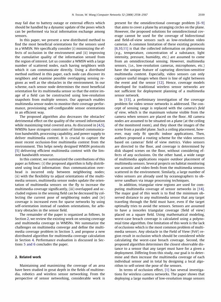
The effect of resolution vs. node density: In Fig. 13, asensing field with several obstacles (represented by blackrectangular areas) and 50 multimedia sensors is shown.Each multimedia sensor is illustrated with a ‘‘small dia-mond” and its vFoV is shown with a dark shaded area.We observe that in highly-occluded environments, a smallnumber of high-resolution camera sensors1 perform muchworse than a large number of low-resolution camera sen-
1 Note that in this context, a high-resolution camera refers to the onethat can capture information from a larger sensing area.
sors. In Fig. 13a, a sensing field with randomly placed eightobstacles of different sizes is given. This field has 50 low-res-olution camera nodes deployed with 30 m range. On theother hand, in Fig. 13b, the same sensing field is installedwith 10 high-resolution camera nodes of 100 m range. Tri-ple-ranged camera sensors in Fig. 13 result in about 10% de-graded total coverage compared to the low-resolutionsensors. Note that the FoVs for the network in Fig. 13 areset using the self-orienting algorithm explained earlier.
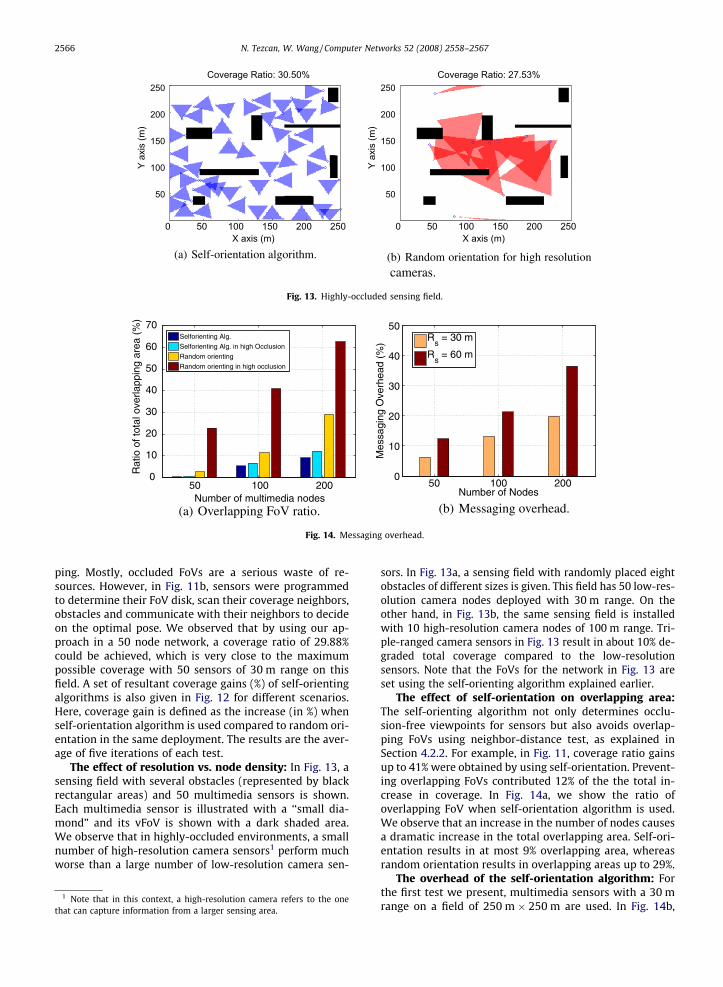
The effect of self-orientation on overlapping area:The self-orienting algorithm not only determines occlu-sion-free viewpoints for sensors but also avoids overlap-ping FoVs using neighbor-distance test, as explained inSection 4.2.2. For example, in Fig. 11, coverage ratio gainsup to 41% were obtained by using self-orientation. Prevent-ing overlapping FoVs contributed 12% of the the total in-crease in coverage. In Fig. 14a, we show the ratio ofoverlapping FoV when self-orientation algorithm is used.We observe that an increase in the number of nodes causesa dramatic increase in the total overlapping area. Self-ori-entation results in at most 9% overlapping area, whereasrandom orientation results in overlapping areas up to 29%.
The overhead of the self-orientation algorithm: Forthe first test we present, multimedia sensors with a 30 mrange on a field of 250 m � 250 m are used. In Fig. 14b,

N. Tezcan, W. Wang / Computer Networks 52 (2008) 2558–2567 2567
we show the ratio of total number of messages used by theself-orienting algorithm to the total number of controlmessages, including routing. As we explained in Section4.3, our algorithm uses OðnÞ messages which is 6% of allcontrol messages on average when N ¼ 50. The ratio in-creases only up to 35% of total control traffic whenN ¼ 200 and Rs = 60 m, indicating a very dense networkwith high-degree of connectivity.
5.3. Observations
From the presented experiments, our observations onmultimedia coverage and self-orientation can be summa-rized as follows:
� Increasing the node density does not increase the cover-age ratio proportionally, on the contrary, it results inlarge overlapping areas.
� In highly-occluded fields, many low-resolution camerasconstitute a much better alternative to few high-resolu-tion camera nodes.
� Self-orientation is a very effective way to increase cover-age ratio while avoiding occlusions and overlappingFoVs.
6. Conclusion
In this paper, we proposed a self-orienting algorithm formultimedia wireless sensor networks in order to attainocclusion-free coverage. We find that (i) the proposedalgorithm uses local information; that is, communicationoverhead is incurred only between neighboring nodes witha complexity of OðNÞ, (ii) the proposed algorithm is fullydistributed, which can operate after initial deploymentand update the orientation of multimedia sensors on thefly, (iii) the proposed algorithm can support prioritized oraccurate observation that require more than multiple in-puts from more than one sensor node, and (iv) coveragecan be increased even for sparse networks by using self-orientation instead of random orientations, for arbitraryobstacles in the sensor field.
References
[1] M. Rahimi, S. Ahmadian, D. Zats, R. Laufer, D. Estrin. Magic ofnumbers in networks of wireless image sensors, in: Proc. of SenSysWorkshop on Distributed Cameras, 2006.
[2] P. Sambhoos, A.B. Hasan, R. Han, T. Lookabaugh, J. Mulligan.Weeblevideo – wide angle field-of-view video sensor networks, in:Proc. SenSys Workshop on Distributed Cameras, 2006.
[3] K.A. Tarabanis, R.Y. Tsai, A. Kaul, Computing occlusion-freeviewpoints, IEEE Transactions on Pattern Analysis and MachineIntelligence 2 (1996) 273–292.
[4] O.B. Akan, Performance of transport protocols for multimediacommunications in wireless sensor networks, IEEECommunications Letters 11 (10) (2007) 826–828.
[5] Y. Gu, Y. Tian, E. Ekici, Real-time multimedia processing in videosensor networks, Signal Processing: Image Communication Journal22 (3) (2007) 237–251.
[6] M. Cardei, M. Thai, W. Wu, Energy-efficient target coverage inwireless sensor networks, in: Proc. IEEE Infocom, Miami, Forida, USA,2005.
[7] H. Gupta, S.R. Das, Q. Gu, Connected sensor cover: self-organizationof sensor networks for efficient query execution, in: Proc. ACMMobihoc, Annapolis, Maryland, USA, 2003.
[8] S. Slijepcevic, M. Potkonjak, Power efficient organization of wirelesssensor networks, in: Proc. IEEE International Conference onCommunications, Helsinki, 2003, pp. 472–476.
[9] D. Tian, N.D. Georganas, A coverage-preserving node schedulingscheme for large wireless sensor networks, in: Proc. First ACM Int.Workshop on Wireless Sensor Networks and Applications, Georgia,USA, 2002.
[10] X. Wang, G. Xing, Y. Zhang, C. Lu, R. Pless, C. Gill, Integrated coverageand connectivity configuration in wireless sensor networks, in: Proc.SenSys, Los Angeles, California, USA, 2003, pp. 28–40.
[11] H. Zhang, J. Hou, Maintaining sensor coverage and connectivity inlarge sensor networks, in: Proc. NSF International Workshop onTheoretical and Algorithmic Aspects of Sensor, Adhoc Wireless, andPeer-to-Peer Networks, 2004.
[12] I.F. Akyildiz, T. Melodia, K.R. Chowdhury, A Survey on WirelessMultimedia Sensor Networks, Computer Networks.
[13] S. Soro, W.B. Heinzelman, On the coverage problem in video-basedwireless sensor networks, in: Proc. of the Second Workshop onBroadband Advanced Sensor Networks (BaseNets ’05), 2005.
[14] J. Adriaens, S. Megerian, M. Potkonjak, Optimal worst-case coverageof directional field-of-view sensor networks, in: Proc. of IEEE SECON,2006.
[15] J. O’Rourke, Art Gallery Theorems and Algorithms, Oxford UniversityPress, New York, 1987.
[16] S. Fleishman, D. Cohen-Or, D. Lischinski, Automatic cameraplacement for image-based modeling, in: Proc. Pacific Graphics,vol. 99, 1999, pp. 12–20.
[17] V. Isler, S. Kannan, K. Daniilidis, Vc-dimension of exterior visibility,IEEE Transactions on Pattern Analysis and Machine Intelligence 26(5) (2004) 667–671.
[18] A. Williams, D. Xie, S. Ou, Distributed smart cameras for aging inplace, in: Proc. SenSys Workshop on Distributed Cameras, 2006.
[19] T. He, C. Huang, B.M. Blum, J.A. Abdelzaher, Range-free localizationschemes for large scale sensor networks, in: In Proc. ACM Mobicom,San Diego, California, USA, 2003, pp. 81–95.
[20] M. Nicolescu, G. Medioni, Electronic pan-tilt-zoom: a solution forintelligent room systems.
[21] M.-F. Huang, Y.-C. Tseng, The coverage problem in a wireless sensornetwork, in: Proc. ACM WSNA, San Diego, CA, USA, 2003.
[22] P. Kulkarni, D. Ganesan, P. Shenoy, Q. Lu, SensEye: a multi-tiercamera sensor network, in: Proc. ACM Multimedia, 2005.
[23] Ns-2, http://www.isi.edu/nsnam/ns.
Nurcan Tezcan received the B.S. and M.S.degrees in computer engineering from Yedi-tepe University, Turkey in 2001 and BogaziciUniversity, Turkey, in 2004, respectively. Sheis currently working toward the Ph.D. degreein computer engineering at the North CarolinaState University, Raleigh. Her current researchinterests are in transport layer protocols,energy-efficient algorithms and performanceanalysis of wireless networks.
Wenye Wang (M’98/ACM’99) received theB.S. and M.S. degrees from Beijing Universityof Posts and Telecommunications, Beijing,China, in 1986 and 1991, respectively. Shealso received the M.S.E.E. and Ph.D. degreefrom Georgia Institute of Technology, Atlanta,Georgia in 1999 and 2002, respectively. She isnow an Assistant Professor with the Depart-ment of Electrical and Computer Engineering,North Carolina State University. Her researchinterests are in mobile and secure computing,quality-of-service (QoS) sensitive networking
protocols in single- and multihop networks. She has served on programcommittees for IEEE INFOCOM, ICC, ICCCN in 2004. Dr. Wang is a recipientof NSF CAREER Award in 2006. She has been a member of the Association
for Computing Machinery since 2002.