computer integrated manufacturing applications - lab … · computer integrated manufacturing...
TRANSCRIPT

Mechatronics
Computer Integrated Manufacturing Applications
Courseware Sample 39468-F0

Order no.: 39468-00
First Edition
Revision level: 02/2015
By the staff of Festo Didactic
© Festo Didactic Ltée/Ltd, Quebec, Canada 2007
Internet: www.festo-didactic.com
e-mail: [email protected]
Printed in Canada
All rights reserved
ISBN 978-2-89640-098-0 (Printed version)
ISBN 978-2-89640-693-7 (CD-ROM)
Legal Deposit – Bibliothèque et Archives nationales du Québec, 2007
Legal Deposit – Library and Archives Canada, 2007
The purchaser shall receive a single right of use which is non-exclusive, non-time-limited and limited
geographically to use at the purchaser's site/location as follows.
The purchaser shall be entitled to use the work to train his/her staff at the purchaser's site/location and
shall also be entitled to use parts of the copyright material as the basis for the production of his/her own
training documentation for the training of his/her staff at the purchaser's site/location with
acknowledgement of source and to make copies for this purpose. In the case of schools/technical
colleges, training centers, and universities, the right of use shall also include use by school and college
students and trainees at the purchaser's site/location for teaching purposes.
The right of use shall in all cases exclude the right to publish the copyright material or to make this
available for use on intranet, Internet and LMS platforms and databases such as Moodle, which allow
access by a wide variety of users, including those outside of the purchaser's site/location.
Entitlement to other rights relating to reproductions, copies, adaptations, translations, microfilming and
transfer to and storage and processing in electronic systems, no matter whether in whole or in part, shall
require the prior consent of Festo Didactic GmbH & Co. KG.
Information in this document is subject to change without notice and does not represent a commitment on
the part of Festo Didactic. The Festo materials described in this document are furnished under a license
agreement or a nondisclosure agreement.
Festo Didactic recognizes product names as trademarks or registered trademarks of their respective
holders.
All other trademarks are the property of their respective owners. Other trademarks and trade names may
be used in this document to refer to either the entity claiming the marks and names or their products.
Festo Didactic disclaims any proprietary interest in trademarks and trade names other than its own.

Safety and Common Symbols
The following safety and common symbols may be used in this manual and on the equipment:
Symbol Description
DANGER indicates a hazard with a high level of risk which, if not avoided, will result in death or serious injury.
WARNING indicates a hazard with a medium level of risk which, if not avoided, could result in death or serious injury.
CAUTION indicates a hazard with a low level of risk which, if not avoided, could result in minor or moderate injury.
CAUTION used without the Caution, risk of danger sign , indicates a hazard with a potentially hazardous situation which, if not avoided, may result in property damage.
Caution, risk of electric shock
Caution, hot surface
Caution, risk of danger
Caution, lifting hazard
Caution, hand entanglement hazard
Notice, non-ionizing radiation
Direct current
Alternating current
Both direct and alternating current
Three-phase alternating current
Earth (ground) terminal
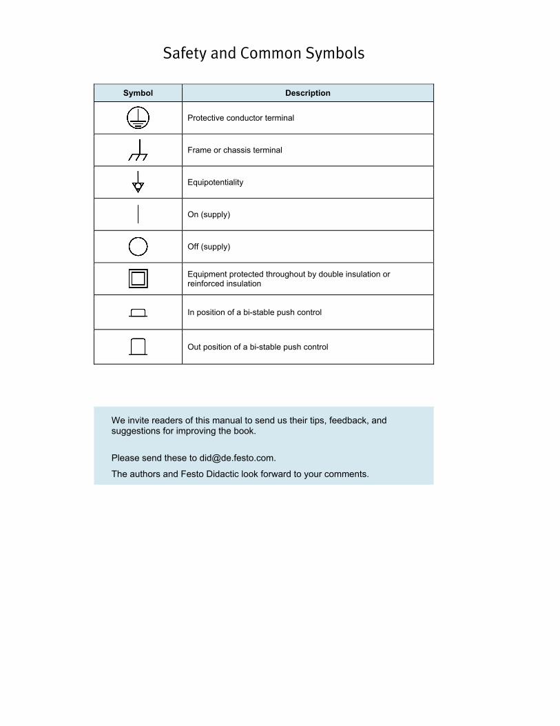
Safety and Common Symbols
Symbol Description
Protective conductor terminal
Frame or chassis terminal
Equipotentiality
On (supply)
Off (supply)
Equipment protected throughout by double insulation or reinforced insulation
In position of a bi-stable push control
Out position of a bi-stable push control
We invite readers of this manual to send us their tips, feedback, and suggestions for improving the book.
Please send these to [email protected].
The authors and Festo Didactic look forward to your comments.
V
Foreword
This document consists of tutorial exercises that allow you to implement the followingapplications:
• milling a part with the Lab-Volt CNC Mill, using the Lab-Volt CNC Mill Software.
• controlling the Lab-Volt Servo Robot and the Linear Slide, using the Lab-VoltRoboCIM 5250 software.
• controlling a manufacturing system that uses the Servo Robot and the CNC Mill.
• controlling the Lab-Volt Servo Robot and the Rotary Carousel, using theLab-Volt RoboCIM 5250 software.
• controlling a manufacturing system that uses the Servo Robot, the RotaryCarousel, and the CNC Mill.
Each exercise consists of a DISCUSSION section describing the application to beimplemented with the related drawings, followed by a practical section giving thesteps to use to implement the application. The files required to perform eachexercise (G and M part program and/or RoboCIM 5250 workspaces) can be foundon the provided CD-ROM.
Before performing the exercises, it is recommended that you go through the followingLab-Volt manuals:
– Servo-Robot System, User Guide (part number 34175-E);– Introduction to Robotics, Student Manual (part number 34175-0);– Familiarization with the CNC Mill, Quick-Start Guide (part number 36783-E);– CNC Mill Software, User Guide (part number 36189-E);– RoboCIM 5250 Software, User Guide (part number 37864-E).
Note: For the sake of conciseness, the term "RoboCIM 5250software" will be referred to as "RoboCIM" or "theRoboCIM software" for the remainder of the manual.

VI
VII
Table of Contents
Introduction . . . . . . . . . . . . . . . . . . . . . . . . . . . . . . . . . . . . . . . . . . . . . . . . . . . . IX
Exercise 1 Milling a Part with the Lab-Volt CNC Mill . . . . . . . . . . . . . . . . . 1-1
Engraving text on square pieces of stock, using the Lab-Volt CNC Mill,model 5600, and the Lab-Volt CNC Mill Software.
Exercise 2 Control of the Lab-Volt Servo Robot and Linear Slide,Using the RoboCIM 5250 Software . . . . . . . . . . . . . . . . . . . . . . 2-1
Operating a system that uses the Lab-Volt Servo Robot to pick up partsfrom a feeder, place them onto a tray, and then transfer them into astorage box.
Exercise 3 Control of a Manufacturing System That Uses theLab-Volt CNC Mill and Servo Robot . . . . . . . . . . . . . . . . . . . . . 3-1
Operating a manufacturing system that combines the milling process ofExercise 1 and the robotics process of Exercise 2: the robot feeds partsto the CNC Mill, which engraves a text on them. The robot transfers themilled parts into a storage box.
Exercise 4 Control of the Lab-Volt Servo Robot and Rotary Carousel,Using the RoboCIM 5250 Software . . . . . . . . . . . . . . . . . . . . . . 4-1
Operating a system that uses the Lab-Volt Servo Robot to pick up partsfrom a feeder, place them on a rotary carousel, and then transfer theminto a storage box.
Exercise 5 Control of a Manufacturing System That Uses the Lab-Volt Servo Robot, CNC Mill, and Rotary Carousel . . . . . . 5-1
Operating a manufacturing system that combines the milling process ofExercise 1 and the robotics process of Exercise 4: the robot feeds partsto the CNC Mill, which engraves a text on them. The robot thentransfers the milled parts onto the carousel and then into a storage box.

VIII
IX
Introduction
The Lab-Volt Servo Robot and CNC Mill can be interconnected, via the RobotController, to create automated work cells, ideal for familiarization with Computer-Integrated Manufacturing (CIM).
Many optional devices can be included in the Lab-Volt work cells to perform variousprocesses: a gravity or pneumatic feeder, a linear slide, a rotary carousel, aconveyor, and various devices for the transfer or storage of parts.
For example, the following describes the operation of an automated work cell thatuses a robot and a CNC Mill. (This work cell will be implemented in the third exerciseof the manual.)
– The robot controller is programmed so that the robot picks a part from a feederand moves it near the mill.
– The robot then verifies if the mill is ready to accept the part. If so, the robotplaces the part into the pneumatic vise of the mill and then withdraws from themill area.
– The robot controller triggers the milling operation to start. The CNC partprogram, which has been downloaded into the mill's memory, is then carried out.
– Once the milling process is complete, the mill signals the robot controller that thepart is milled. This causes the robot to remove the part from the vise of the milland transfer it to a finished-goods location. A new cycle then begins.
The Simulation mode of the RoboCIM software and the Emulate function of theCNC Mill Software allow the student to test the operation of the implemented workcells before placing them into operation.
The program files required to perform the exercises in this manual are on theCD-ROM (part number 39557).

X

Sample Exercise
Extracted from
Student Manual

4-1
Exercise 4
Control of the Lab-Volt Servo Robot and Rotary Carousel,Using the RoboCIM 5250 Software
EXERCISE OBJECTIVE
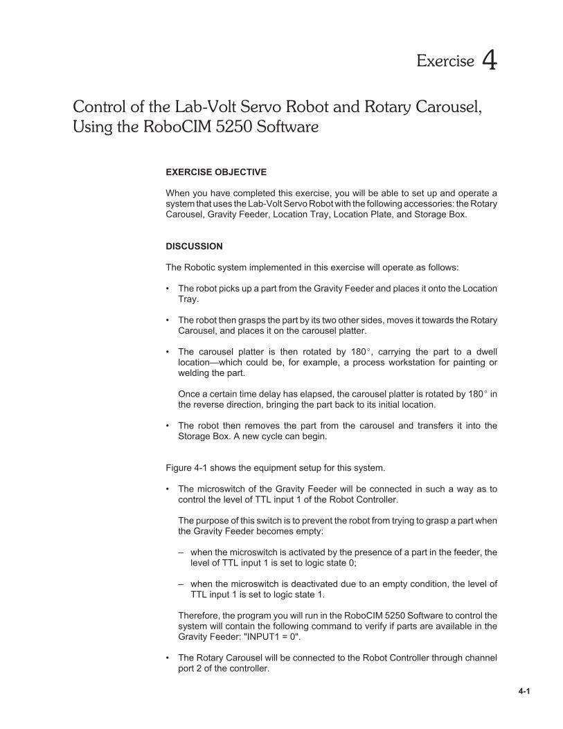
When you have completed this exercise, you will be able to set up and operate asystem that uses the Lab-Volt Servo Robot with the following accessories: the RotaryCarousel, Gravity Feeder, Location Tray, Location Plate, and Storage Box.
DISCUSSION
The Robotic system implemented in this exercise will operate as follows:
• The robot picks up a part from the Gravity Feeder and places it onto the LocationTray.
• The robot then grasps the part by its two other sides, moves it towards the RotaryCarousel, and places it on the carousel platter.
• The carousel platter is then rotated by 180 , carrying the part to a dwelllocation—which could be, for example, a process workstation for painting orwelding the part.
Once a certain time delay has elapsed, the carousel platter is rotated by 180 inthe reverse direction, bringing the part back to its initial location.
• The robot then removes the part from the carousel and transfers it into theStorage Box. A new cycle can begin.
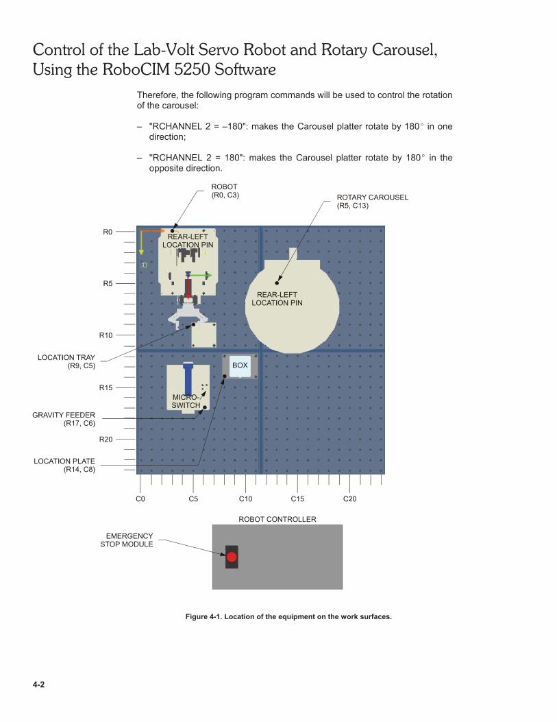
Figure 4-1 shows the equipment setup for this system.
• The microswitch of the Gravity Feeder will be connected in such a way as tocontrol the level of TTL input 1 of the Robot Controller.
The purpose of this switch is to prevent the robot from trying to grasp a part whenthe Gravity Feeder becomes empty:
– when the microswitch is activated by the presence of a part in the feeder, thelevel of TTL input 1 is set to logic state 0;
– when the microswitch is deactivated due to an empty condition, the level ofTTL input 1 is set to logic state 1.
Therefore, the program you will run in the RoboCIM 5250 Software to control thesystem will contain the following command to verify if parts are available in theGravity Feeder: "INPUT1 = 0".
• The Rotary Carousel will be connected to the Robot Controller through channelport 2 of the controller.
Control of the Lab-Volt Servo Robot and Rotary Carousel,Using the RoboCIM 5250 Software
4-2
Therefore, the following program commands will be used to control the rotationof the carousel:
– "RCHANNEL 2 = –180": makes the Carousel platter rotate by 180 in onedirection;
– ''RCHANNEL 2 = 180": makes the Carousel platter rotate by 180 in theopposite direction.
Figure 4-1. Location of the equipment on the work surfaces.
Control of the Lab-Volt Servo Robot and Rotary Carousel,Using the RoboCIM 5250 Software
4-3
Prerequisites
Before you begin the practical section of the exercise, make sure the followingrequirements are met.
1. The Robot Controller must be configured to detect the Rotary Carousel onChannel 2, using the hand-held terminal.
Note: For detailed information on how to configure the RobotController for detection of the Rotary Carousel on a givenchannel, refer to Section 3, "Hand-Held Terminal, Configuration"of the Lab-Volt User Guide "Servo Robot System" (part number34175-E).
2. The robot and Rotary Carousel must be calibrated according to the proceduresfound in Appendix D of the Lab-Volt User Guide "RoboCIM 5250 Software" (partnumber 37864-E).
3. You must have gone through the Application Example found in Section 7 of theLab-Volt User Guide mentioned in step 2.
Procedure summary
In this exercise, you will test the provided program, 39468_EX4_**.rcw, in theSimulation mode, using the emulator of the RoboCIM 5250 software. This will allowyou to see how the system operates before placing it into operation.
Next you will set up the equipment and run the RoboCIM program in the Controlmode. You will observe the system operation by steps, and determine if pointsregistered in the program need correction. If so, you will modify the coordinates ofthe points that need correction.
Finally, you will change the way in which the robot grasps parts and places them onthe carousel platter by modifying the coordinates of specific points.
EQUIPMENT REQUIRED
• Servo Robot System, Model 5250 (Servo Robot, Robot Controller, Hand-Heldterminal, Emergency Stop module, and Leads);
• Work Surfaces (two surfaces needed if Model 46604 is used, or four surfacesneeded if Model 6309 is used);
• Spacer mounting brackets to mount and lock the work surfaces into place(Model 39035);
• Rotary Carousel, Model 5208-1;• Square-Part Gravity Feeder, Model 5119;• Location Plate, Model 38001;• Storage Box, Model 38003;• Location Tray, Model 38685;• Square parts, [50 mm (2-in) wide, 50-mm (2-in) long, 12.7-mm (0.5-in) thick].
Control of the Lab-Volt Servo Robot and Rotary Carousel,Using the RoboCIM 5250 Software
4-4
PROCEDURE
Program Testing in the Simulation Mode
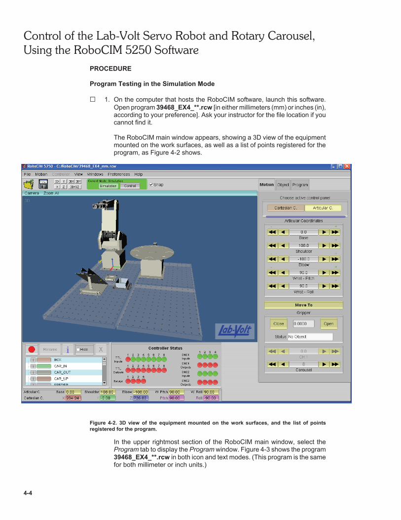
G 1. On the computer that hosts the RoboCIM software, launch this software.Open program 39468_EX4_**.rcw [in either millimeters (mm) or inches (in),according to your preference]. Ask your instructor for the file location if youcannot find it.
The RoboCIM main window appears, showing a 3D view of the equipmentmounted on the work surfaces, as well as a list of points registered for theprogram, as Figure 4-2 shows.
Figure 4-2. 3D view of the equipment mounted on the work surfaces, and the list of pointsregistered for the program.
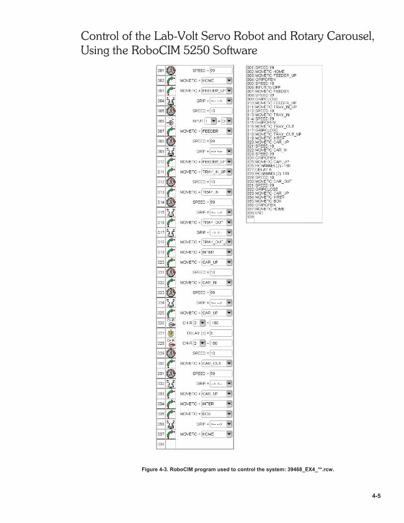
In the upper rightmost section of the RoboCIM main window, select theProgram tab to display the Program window. Figure 4-3 shows the program39468_EX4_**.rcw in both icon and text modes. (This program is the samefor both millimeter or inch units.)
Control of the Lab-Volt Servo Robot and Rotary Carousel,Using the RoboCIM 5250 Software
4-5
Figure 4-3. RoboCIM program used to control the system: 39468_EX4_**.rcw.
Control of the Lab-Volt Servo Robot and Rotary Carousel,Using the RoboCIM 5250 Software
4-6
G 2. Before testing the program in the Simulation mode, observe the location ofeach point registered in the browser of the Point Recorder panel.
Note: To see the location of a point in the 3D view, click on thePoint visibility button next to the point. To view the pointcoordinates, select the point by clicking on its name and then clickon the Information button in the header section of the PointRecorder panel.
G 3. Run the program by steps in the Simulation mode: in the Toolbar ofRoboCIM, make sure the Communication toolbar isset to Simulation (Simulation button in green, Control button in gray).
In the Program window of RoboCIM, make sure the program is displayed inthe icon mode. Run the program by steps by clicking on the button ofthe animation toolbar repeatedly, and fill in the sentences below.
a. The end effector is first (lowered/raised) toward thebottom of the (Location Tray/Gravity Feeder/Storage Box), then thegripper is (closed/opened).
Note: In the Simulation mode, the reduction of the speed as theend effector approaches an object is not visible.
b. The program then verifies if parts are available in the Gravity Feeder,based on the signal sent by the microswitch of the Gravity Feeder to theRobot Controller (the program is at command "INPUT1 = 0").
Since TTL Input LED 1 in the Controller Status panel of the RoboCIMmain window is in (red/green), a low level (OFF) ispresent at TTL input 1 and, therefore, (a part/no part) isavailable in the Gravity Feeder.
Note: When the program is run in the Simulation mode, alow (OFF) level is automatically simulated at TTL input 1 as longas the simulated number of parts in the feeder (as set in theRoboCIM Object window displayed upon selection of the GravityFeeder) is not 0. Running the program many times will eventuallycause the number of simulated parts to become null, and a high(ON) level to occur at TTL Input 1, indicating the absence of partsin the feeder and causing the program to become stuck atcommand INPUT1 = 0. In that case, set the Number of Parts fieldin the Object window for the Gravity Feeder to a non-null value(e.g. 5), to continue to run the program in the Simulation mode.Note that in the Control mode, the program will continue to run aslong as parts are detected in the feeder, that is, even if thenumber of parts simulated by the program becomes null, becausein that case, the program reads the actual signal provided by themicroswitch of the Gravity Feeder.
Control of the Lab-Volt Servo Robot and Rotary Carousel,Using the RoboCIM 5250 Software
4-7
c. Therefore, the end effector picks a part from the , raisesit above the work surface, and brings it right above the (Gravity Feeder/Storage Box/Location Tray).
d. The speed is reduced, then the end effector places the part onto the . The gripper is (closed/opened) to releasethe part.
e. The gripper is rotated by (90 /45 ) and then closed to grasp thepart by its two (other sides/opposite corners).
f. The part is raised above the work surface and moved, via anintermediate point, towards the (Gravity Feeder/RotaryCarousel/Location Tray). It is brought right over one of the hollowsquares of the carousel platter.
g. The part is placed in the hollow square of the carousel platter, then thegripper is (closed/opened) and (loweredbelow/raised over) the platter.
h. The platter of the Rotary Carousel is then rotated by 180 , whichcorresponds to program command , thus carrying the partto a dwell location.
i. After a dwell time of seconds (program command ), the Rotary Carousel is rotated by 180 in the reversedirection (program command ), thus returning the part tothe initial location.
j. The end effector is lowered toward the platter. It grasps the part by twoopposite (sides/corners), raises it above the platter andmoves it, via an intermediate point, right over the (GravityFeeder/Storage Box/Location Tray).
k. The gripper is opened to drop the part into the box. The end effectorthen returns to its home position and a new cycle can begin.
l. When the Gravity Feeder becomes empty, the microswitch of thisfeeder becomes deactuated. This causes the program to stop atprogram command (INPUT1 = 0/MOVETO = HOME). Inthe RoboCIM Controller Status panel, TTL Input LED 1 is in (green/red), indicating that a high level (ON) is present atTTL input 1 (no part detected).
Control of the Lab-Volt Servo Robot and Rotary Carousel,Using the RoboCIM 5250 Software
4-8
G 4. Once you are familiar with the operation of the system, run the programcontinuously by clicking on the Run Continuously buttonand then the Execute button in the animation toolbar of the Program
window. Then, stop program execution by clicking on the Stop button.
Program Testing in the Control Mode
Note: Before proceeding with the next steps, make sure thatChannel 2 of the Robot Controller is assigned to the RotaryCarousel (CH 2 :CAROUSEL) and that the gripper is set to servo(GRIP:SERVO) in the configuration menu of the controller hand-held terminal. [For detailed information on how to set the type ofgripper used, and configure the controller for detection of theRotary Carousel on a given channel, refer to Section 3,"Hand-Held Terminal, Configuration" of the Lab-Volt User Guide"Servo Robot System" (part number 34175-E)].
Moreover, make sure that the robot and Rotary Carousel havebeen calibrated according to the calibration procedures providedin Appendix D of the Lab-Volt User Guide "RoboCIM 5250Software" (part number 37864-E).
CAUTION!
When you are working with moving equipment, make sureyou are not wearing anything that might get caught in theequipment, such as a tie or jewelry. If your hair is long, tie itout of the way. Pay particular attention to keep your hands,other body parts, or anything attached to your body out ofthe mechanisms of the robot while the robot is moving.
Positioning the Equipment
G 5. Position the Robot, Rotary Carousel, Location Tray, Gravity Feeder, andStorage Box as shown in Figure 4-1.
Note: The equipment can be positioned in a way different thanthat illustrated in Figure 4-1. The important point is that therelative position of the objects (their position with respect to eachother) on the work surfaces be the same as that shown inFigure 4-1.
Connecting the Equipment
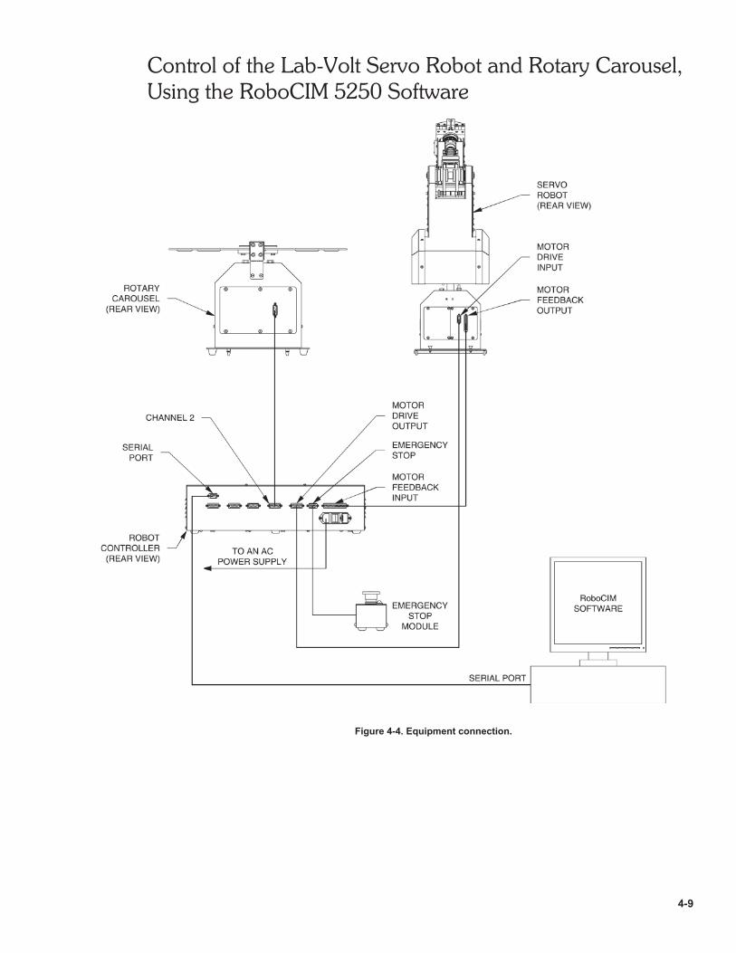
G 6. Connect the equipment as shown in Figure 4-4. (The Rotary Carousel mustbe connected to channel 2 of the Robot Controller.)
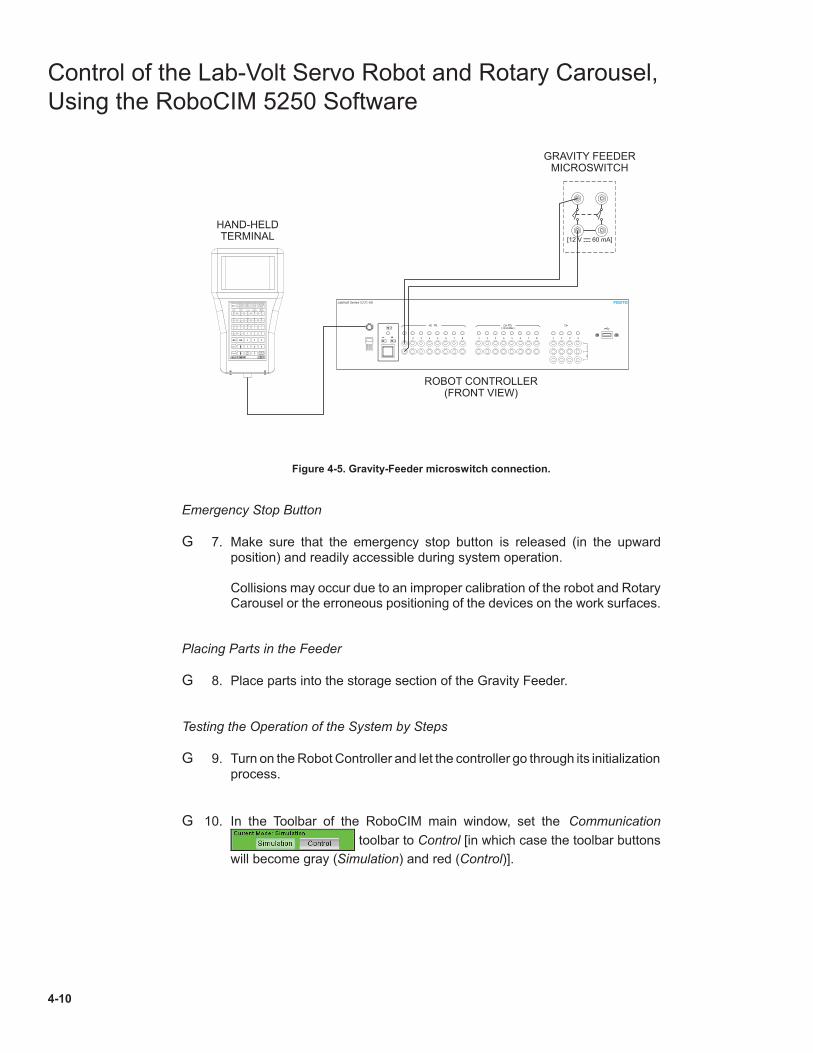
As Figure 4-5 shows, connect the normally-open contact of the GravityFeeder microswitch to TTL input 1 of the Robot Controller.
Control of the Lab-Volt Servo Robot and Rotary Carousel,Using the RoboCIM 5250 Software
4-9
Figure 4-4. Equipment connection.
Control of the Lab-Volt Servo Robot and Rotary Carousel,
Using the RoboCIM 5250 Software
4-10
Figure 4-5. Gravity-Feeder microswitch connection.
Emergency Stop Button
G 7. Make sure that the emergency stop button is released (in the upwardposition) and readily accessible during system operation.
Collisions may occur due to an improper calibration of the robot and RotaryCarousel or the erroneous positioning of the devices on the work surfaces.
Placing Parts in the Feeder
G 8. Place parts into the storage section of the Gravity Feeder.
Testing the Operation of the System by Steps
G 9. Turn on the Robot Controller and let the controller go through its initializationprocess.
G 10. In the Toolbar of the RoboCIM main window, set the Communication
toolbar to Control [in which case the toolbar buttons
will become gray (Simulation) and red (Control)].
SPACE
ENTERDEL
ESC
SHIFT
0
987
654
321)
*#
(
,/
?
Z
W
Y
V
X
U
P
K
Q
L
R
M
S
N
T
O
J
E
I
D
H
C
G
B
F
A
ClearError
MainMenu
TeachMenu
ESCSuspdOper.
.
Power
Run Teach Error Susp
[ ]12 V 60 mA¤
ROBOT CONTROLLER(FRONT VIEW)
HAND-HELDTERMINAL
GRAVITY FEEDERMICROSWITCH
Control of the Lab-Volt Servo Robot and Rotary Carousel,Using the RoboCIM 5250 Software
4-11
Note: If the hard home positioning of the robot and Rotarycarousel have not been done yet, a dialog box will appear toindicate that this will be performed. Click toaccept and close the box.
G 11. You will now run the program by steps. Before you do so, read theCAUTION below.
CAUTION!
Be sure to watch the robot operate closely, and be ready to press onthe emergency stop button. If the robot is in danger of colliding withan obstacle, press on the emergency stop pushbutton, which willcause all the system operations to be halted, and the red LEDindicator next to this button to turn on. Thereafter, use the followingsteps to return the system into operation:
– Release the emergency stop pushbutton by using the required key,which will cause the red LED indicator next to this button to turn off.
– In the RoboCIM software, select Release Emergency Stop from theController menu of the RoboCIM menu bar.
– Select the Motion tab of RoboCIM to display the Motion window.– In the Cartesian or Articular Coordinates panel of the Motion window,
carefully move the end effector of the robot, using the arrow keys,in order to withdraw the end effector to a safe area so that no collisionswill occur when the robot is returned to the soft home position.
– If a square part is currently gripped by the end effector, open the gripperto release it.
– Return the robot to the soft home position by selecting Soft Home fromthe Motion menu of the RoboCIM menu bar.
– In the Toolbar of the RoboCIM main menu, set the Communicationtoolbar to Simulation.
– Remove any square part on the equipment setup that is not located inthe Gravity Feeder or the Storage Box. Be sure that there is no part leftin the Location Tray or Rotary Carousel.
– Correct the problem. Collisions may occur due to an impropercalibration of the robot and Rotary Carousel or the erroneouspositioning of the devices on the work surfaces.
– Once the problem has been corrected, set the Communication toolbarof RoboCIM to Control and test the operation of the system as directedin step 12.
G 12. Run the program by steps: click on Execute step by step in theRoboCIM Program window.
Observe the action performed by the robot for each command. Whileobserving the system operation, determine if points registered in theprogram will need a correction of their coordinates: for example,
– when placed in the Location Tray, the part must sit correctly in thehollow square area of the tray.
Control of the Lab-Volt Servo Robot and Rotary Carousel,Using the RoboCIM 5250 Software
4-12
– when grasped by the two other sides, the part should be grasped atequal heights.
– when placed on the carousel platter, the part must sit correctly in thehollow square area.
– once it has been rotated by the carousel, the part should be grasped atequal heights.
Note: It is normal for the coordinates of some points registered inthe initial program to require some correction, due to backlashbetween the gears of the transmission coupled to the motors thatdrive the robot. Thus, because of the backlash, the end effectorof the robot, when moved to a registered point, may not exactlybe at the physical location specified for that point. Therefore, thecoordinates of the registered point might require some correction,for the end effector to actually go to a precise location.
To correct the coordinates of a point, follow the procedure below.
a. Using the Execute step by step command in the RoboCIMProgram window, move the end effector by steps until it reaches thepoint that needs correction and the program command correspondingto that point [MOVETO ‹Point Name›] becomes highlighted inRoboCIM.
(For example, if, when placed on the Location Tray, the part does notsit correctly in the hollow square area of the tray, move the end effectorto point TRAY_IN, that is, until the highlighted command isMOVETO TRAY_IN).
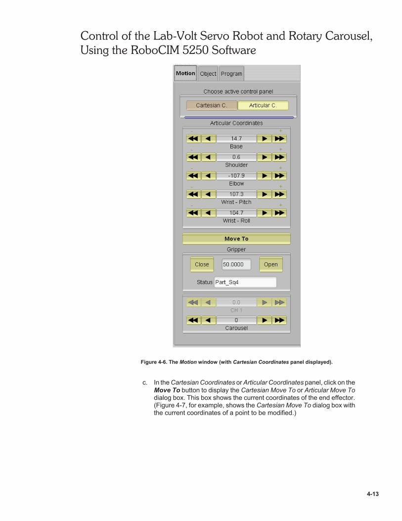
b. Select the Motion tab of RoboCIM to display the Motion window. In theheader section of this window, select either the Cartesian Coordinatesor Articular Coordinates tab, depending upon the mode of coordinatesyou want to display to make the correction. (Figure 4-6, for example,shows the Motion window when the Cartesian Coordinates panel isselected.)
Control of the Lab-Volt Servo Robot and Rotary Carousel,Using the RoboCIM 5250 Software
4-13
Figure 4-6. The Motion window (with Cartesian Coordinates panel displayed).
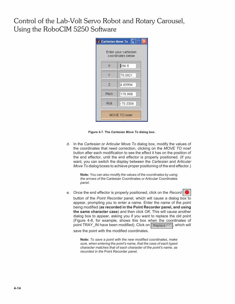
c. In the Cartesian Coordinates or Articular Coordinates panel, click on theMove To button to display the Cartesian Move To or Articular Move Todialog box. This box shows the current coordinates of the end effector.(Figure 4-7, for example, shows the Cartesian Move To dialog box withthe current coordinates of a point to be modified.)
Control of the Lab-Volt Servo Robot and Rotary Carousel,Using the RoboCIM 5250 Software
4-14
Figure 4-7. The Cartesian Move To dialog box.
d. In the Cartesian or Articular Move To dialog box, modify the values ofthe coordinates that need correction, clicking on the MOVE TO now!button after each modification to see the effect it has on the position ofthe end effector, until the end effector is properly positioned. (If youwant, you can switch the display between the Cartesian and ArticularMove To dialog boxes to achieve proper positioning of the end effector.)
Note: You can also modify the values of the coordinates by usingthe arrows of the Cartesian Coordinates or Articular Coordinatespanel.
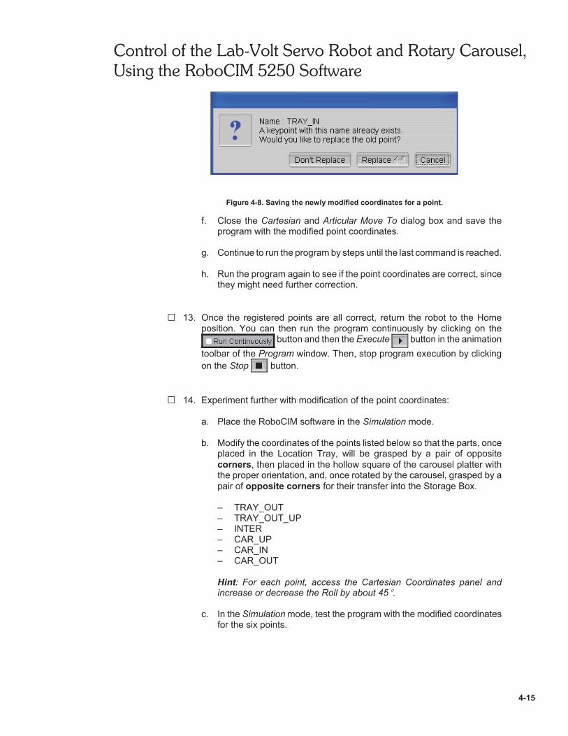
e. Once the end effector is properly positioned, click on the Record button of the Point Recorder panel, which will cause a dialog box toappear, prompting you to enter a name. Enter the name of the pointbeing modified (as recorded in the Point Recorder panel, and usingthe same character case) and then click OK. This will cause anotherdialog box to appear, asking you if you want to replace the old point(Figure 4-8, for example, shows this box when the coordinates ofpoint TRAY_IN have been modified). Click on , which willsave the point with the modified coordinates.
Note: To save a point with the new modified coordinates, makesure, when entering the point's name, that the case of each typedcharacter matches that of each character of the point's name, asrecorded in the Point Recorder panel.
Control of the Lab-Volt Servo Robot and Rotary Carousel,Using the RoboCIM 5250 Software
4-15
Figure 4-8. Saving the newly modified coordinates for a point.
f. Close the Cartesian and Articular Move To dialog box and save theprogram with the modified point coordinates.
g. Continue to run the program by steps until the last command is reached.
h. Run the program again to see if the point coordinates are correct, sincethey might need further correction.
G 13. Once the registered points are all correct, return the robot to the Homeposition. You can then run the program continuously by clicking on the
button and then the Execute button in the animationtoolbar of the Program window. Then, stop program execution by clickingon the Stop button.
G 14. Experiment further with modification of the point coordinates:
a. Place the RoboCIM software in the Simulation mode.
b. Modify the coordinates of the points listed below so that the parts, onceplaced in the Location Tray, will be grasped by a pair of oppositecorners, then placed in the hollow square of the carousel platter withthe proper orientation, and, once rotated by the carousel, grasped by apair of opposite corners for their transfer into the Storage Box.
– TRAY_OUT– TRAY_OUT_UP– INTER– CAR_UP– CAR_IN– CAR_OUT
Hint: For each point, access the Cartesian Coordinates panel andincrease or decrease the Roll by about 45 .
c. In the Simulation mode, test the program with the modified coordinatesfor the six points.

Control of the Lab-Volt Servo Robot and Rotary Carousel,Using the RoboCIM 5250 Software
4-16
d. Once the program executes properly, place the RoboCIM software inthe Control mode. Verify that the system operates properly, and readjustthe coordinates of the points that need correction, if any. Once thesystem operates proper ly , save the program as39468_EX4_Experiment_**.rcw.
G 15. Place the RoboCIM software in the Simulation mode, then turn off the RobotController.
CONCLUSION
In this exercise, you set up and operated a system that made the robot pick up partsfrom a gravity feeder and place them on a rotary carousel. The carousel was rotatedby 180 and then allowed to dwell to simulate the processing of the parts at aworkstation. The carousel was then rotated by 180 in the opposite direction toreturn the parts to their original location. The parts were then transferred into astorage box.
REVIEW QUESTIONS
1. Which two lines of the RoboCIM program made the carousel rotate by 180 inone direction and then the other?
2. In this exercise, what was the logic state of the TTL input signal provided by theGravity Feeder microswitch when parts were present in the Gravity Feeder?When the feeder was empty?
3. At what command did the RoboCIM program stop when the Gravity Feederbecame empty, causing the system operation to stop? Explain.
4. Which program line was used to make the rotary carousel dwell at a location for5 seconds?

Control of the Lab-Volt Servo Robot and Rotary Carousel,Using the RoboCIM 5250 Software
4-17
5. Given a MOVETO command used to make the robot grasp a part by twoopposite sides, how can the cartesian coordinates of the point associated withthis command be modified to make the robot grasp the part by the two othersides instead? By two opposite corners?

4-18

Sample
Extracted from
Instructor Guide


Computer Integrated Manufacturing Applications
5
EXERCISE 4 CONTROL OF THE LAB-VOLT SERVO ROBOTAND ROTARY CAROUSEL, USING THEROBOCIM 5250 SOFTWARE
ANSWERS TO PROCEDURE STEP QUESTIONS
G 3. a. The end effector is first lowered toward the bottom of the GravityFeeder, then the gripper is opened.
b. Since TTL Input LED 1 in the Controller Status panel of the RoboCIMmain window is in red, a low level (OFF) is present at TTL input 1 and,therefore, a part is available in the Gravity Feeder.
c. Therefore, the end effector picks a part from the Gravity Feeder, raisesit above the work surface, and brings it right above the Location Tray.
d. The speed is reduced, then the end effector places the part onto theLocation Tray. The gripper is opened to release the part.
e. The gripper is rotated by 90 and then closed to grasp the part by its twoother sides.
f. The part is raised above the work surface and moved, via anintermediate point, towards the Rotary Carousel. It is brought right overone of the hollow squares of the carousel platter.
g. The part is placed in the hollow square of the carousel platter, then thegripper is opened and raised over the platter.
h. The platter of the Rotary Carousel is then rotated by 180 in onedirect ion, which corresponds to program commandRCHANNEL 2 = –180 , thus carrying the part to a dwell location.
i. After a dwell time of 5 seconds [program command DELAY (s) = 5], theRotary Carousel is rotated by 180 in the reverse direction (programcommand RCHANNEL 2 = 180 ), thus returning the part to the initiallocation.
j. The end effector is lowered toward the platter. It grasps the part by twoopposite sides, raises it above the platter and moves it, via anintermediate point, right over the Storage Box.
k. The gripper is opened to drop the part into the box. The end effectorthen returns to its home position and a new cycle can begin.
l. When the Gravity Feeder becomes empty, the microswitch of thisfeeder becomes deactuated. This causes the program to stop atprogram command INPUT1 = 0. In the RoboCIM Controller Statuspanel, TTL Input LED 1 is in green, indicating that a high level (ON) ispresent at TTL input 1 (no part detected).
Computer Integrated Manufacturing Applications
6
ANSWERS TO REVIEW QUESTIONS
1. The program lines "RCHANNEL 2 = –180" and "RCHANNEL 2 = 180".
2. When parts were present in the feeder, the Gravity Feeder microswitch wasactivated, causing TTL input 1 to be at logic state 0.
When the Gravity Feeder was empty, the microswitch was deactivated, causingTTL input 1 to be at logic state 1.
3. When the feeder became empty, the RoboCIM program stopped atcommand INPUT1 = 0 (OFF), because a high (ON) TTL logic level was presentat TTL input 1.
4. The program command "DELAY (s) = 5"
5. To make the robot grasp the part by the two other sides, the Roll is increased ordecreased by 90 .
To make the robot grasp the part by two opposite corners, the Roll is increasedor decreased by 45 .
EXERCISE 5 CONTROL OF A MANUFACTURING SYSTEMTHAT USES THE LAB-VOLT SERVO ROBOT,CNC MILL, AND ROTARY CAROUSEL
ANSWERS TO PROCEDURE STEP QUESTIONS
G 4. a. The end effector is first lowered toward the bottom of the GravityFeeder and the gripper is opened.
b. Since TTL Input LED 1 in the Controller Status panel of the RoboCIMmain window is in red, a low or "OFF" level is present at TTL input 1,indicating the presence of a part in the feeder.
c. Therefore, the end effector picks a part from the feeder and then movesit right above the Location Tray, places the part on it, releases the part,and then grasps it by opposite corners.
e. The end effector places the part in the pneumatic vise of the CNC Mill,and then retracts out of the mill area, pausing near the open (right-hand)side of the mill (command MOVETO = MACHINING).
i. At that point, the program makes the Robot controller send a low-(OFF)level signal to the CNC Mill to indicate that the milled part has beenwithdrawn from the mill: therefore, command OUTPUT1 (CNC1) = O is