computer integrated manufacturing applications, 4 … of the lab-volt servo robot and rotary...
TRANSCRIPT
4-1
Exercise 4
Control of the Lab-Volt Servo Robot and Rotary Carousel,
Using the RoboCIM 5250 Software
EXERCISE OBJECTIVE
When you have completed this exercise, you will be able to set up and operate asystem that uses the Lab-Volt Servo Robot with the following accessories: the RotaryCarousel, Gravity Feeder, Location Tray, Location Plate, and Storage Box.
DISCUSSION
The Robotic system implemented in this exercise will operate as follows:
• The robot picks up a part from the Gravity Feeder and places it onto the LocationTray.
• The robot then grasps the part by its two other sides, moves it towards the RotaryCarousel, and places it on the carousel platter.
• The carousel platter is then rotated by 180 , carrying the part to a dwelllocation—which could be, for example, a process workstation for painting orwelding the part.
Once a certain time delay has elapsed, the carousel platter is rotated by 180 inthe reverse direction, bringing the part back to its initial location.
• The robot then removes the part from the carousel and transfers it into theStorage Box. A new cycle can begin.
Figure 4-1 shows the equipment setup for this system.
• The microswitch of the Gravity Feeder will be connected in such a way as tocontrol the level of TTL input 1 of the Robot Controller.
The purpose of this switch is to prevent the robot from trying to grasp a part whenthe Gravity Feeder becomes empty:
– when the microswitch is activated by the presence of a part in the feeder, thelevel of TTL input 1 is set to logic state 0;
– when the microswitch is deactivated due to an empty condition, the level ofTTL input 1 is set to logic state 1.
Therefore, the program you will run in the RoboCIM 5250 Software to control thesystem will contain the following command to verify if parts are available in theGravity Feeder: "INPUT1 = 0".
• The Rotary Carousel will be connected to the Robot Controller through channelport 2 of the controller.

Control of the Lab-Volt Servo Robot and Rotary Carousel,
Using the RoboCIM 5250 Software
4-2
Therefore, the following program commands will be used to control the rotationof the carousel:
– "RCHANNEL 2 = –180": makes the Carousel platter rotate by 180 in onedirection;
– ''RCHANNEL 2 = 180": makes the Carousel platter rotate by 180 in theopposite direction.
Figure 4-1. Location of the equipment on the work surfaces.
Control of the Lab-Volt Servo Robot and Rotary Carousel,
Using the RoboCIM 5250 Software
4-3
Prerequisites
Before you begin the practical section of the exercise, make sure the followingrequirements are met.
1. The Robot Controller must be configured to detect the Rotary Carousel onChannel 2, using the hand-held terminal.
Note: For detailed information on how to configure the RobotController for detection of the Rotary Carousel on a givenchannel, refer to Section 3, "Hand-Held Terminal, Configuration"of the Lab-Volt User Guide "Servo Robot System" (part number34175-E).
2. The robot and Rotary Carousel must be calibrated according to the proceduresfound in Appendix D of the Lab-Volt User Guide "RoboCIM 5250 Software" (partnumber 37864-E).
3. You must have gone through the Application Example found in Section 7 of theLab-Volt User Guide mentioned in step 2.
Procedure summary
In this exercise, you will test the provided program, 39468_EX4_**.rcw, in theSimulation mode, using the emulator of the RoboCIM 5250 software. This will allowyou to see how the system operates before placing it into operation.
Next you will set up the equipment and run the RoboCIM program in the Controlmode. You will observe the system operation by steps, and determine if pointsregistered in the program need correction. If so, you will modify the coordinates ofthe points that need correction.
Finally, you will change the way in which the robot grasps parts and places them onthe carousel platter by modifying the coordinates of specific points.
EQUIPMENT REQUIRED
• Servo Robot System, Model 5250 (Servo Robot, Robot Controller, Hand-Heldterminal, Emergency Stop module, and Leads);
• Work Surfaces (two surfaces needed if Model 46604 is used, or four surfacesneeded if Model 6309 is used);
• Spacer mounting brackets to mount and lock the work surfaces into place(Model 39035);
• Rotary Carousel, Model 5208-1;• Square-Part Gravity Feeder, Model 5119;• Location Plate, Model 38001;• Storage Box, Model 38003;• Location Tray, Model 38685;• Square parts, [50 mm (2-in) wide, 50-mm (2-in) long, 12.7-mm (0.5-in) thick].

Control of the Lab-Volt Servo Robot and Rotary Carousel,
Using the RoboCIM 5250 Software
4-4
PROCEDURE
Program Testing in the Simulation Mode
G 1. On the computer that hosts the RoboCIM software, launch this software.
Open program 39468_EX4_**.rcw [in either millimeters (mm) or inches (in),according to your preference]. Ask your instructor for the file location if youcannot find it.
The RoboCIM main window appears, showing a 3D view of the equipmentmounted on the work surfaces, as well as a list of points registered for theprogram, as Figure 4-2 shows.
Figure 4-2. 3D view of the equipment mounted on the work surfaces, and the list of points
registered for the program.
In the upper rightmost section of the RoboCIM main window, select theProgram tab to display the Program window. Figure 4-3 shows the program
39468_EX4_**.rcw in both icon and text modes. (This program is the samefor both millimeter or inch units.)

Control of the Lab-Volt Servo Robot and Rotary Carousel,
Using the RoboCIM 5250 Software
4-5
Figure 4-3. RoboCIM program used to control the system: 39468_EX4_**.rcw.
Control of the Lab-Volt Servo Robot and Rotary Carousel,
Using the RoboCIM 5250 Software
4-6
G 2. Before testing the program in the Simulation mode, observe the location ofeach point registered in the browser of the Point Recorder panel.
Note: To see the location of a point in the 3D view, click on the
Point visibility button next to the point. To view the point
coordinates, select the point by clicking on its name and then click
on the Information button in the header section of the Point
Recorder panel.
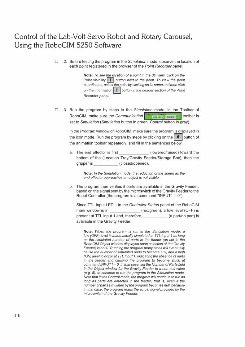
G 3. Run the program by steps in the Simulation mode: in the Toolbar of
RoboCIM, make sure the Communication toolbar is
set to Simulation (Simulation button in green, Control button in gray).
In the Program window of RoboCIM, make sure the program is displayed in
the icon mode. Run the program by steps by clicking on the button of
the animation toolbar repeatedly, and fill in the sentences below.
a. The end effector is first (lowered/raised) toward the
bottom of the (Location Tray/Gravity Feeder/Storage Box), then the
gripper is (closed/opened).
Note: In the Simulation mode, the reduction of the speed as theend effector approaches an object is not visible.
b. The program then verifies if parts are available in the Gravity Feeder,based on the signal sent by the microswitch of the Gravity Feeder to theRobot Controller (the program is at command "INPUT1 = 0").
Since TTL Input LED 1 in the Controller Status panel of the RoboCIM
main window is in (red/green), a low level (OFF) is
present at TTL input 1 and, therefore, (a part/no part) is
available in the Gravity Feeder.
Note: When the program is run in the Simulation mode, alow (OFF) level is automatically simulated at TTL input 1 as longas the simulated number of parts in the feeder (as set in theRoboCIM Object window displayed upon selection of the GravityFeeder) is not 0. Running the program many times will eventuallycause the number of simulated parts to become null, and a high(ON) level to occur at TTL Input 1, indicating the absence of partsin the feeder and causing the program to become stuck atcommand INPUT1 = 0. In that case, set the Number of Parts fieldin the Object window for the Gravity Feeder to a non-null value(e.g. 5), to continue to run the program in the Simulation mode.Note that in the Control mode, the program will continue to run aslong as parts are detected in the feeder, that is, even if thenumber of parts simulated by the program becomes null, becausein that case, the program reads the actual signal provided by themicroswitch of the Gravity Feeder.

Control of the Lab-Volt Servo Robot and Rotary Carousel,
Using the RoboCIM 5250 Software
4-7
c. Therefore, the end effector picks a part from the , raises
it above the work surface, and brings it right above the
(Gravity Feeder/Storage Box/Location Tray).
d. The speed is reduced, then the end effector places the part onto the
. The gripper is (closed/opened) to release
the part.
e. The gripper is rotated by (90 /45 ) and then closed to grasp the
part by its two (other sides/opposite corners).
f. The part is raised above the work surface and moved, via an
intermediate point, towards the (Gravity Feeder/Rotary
Carousel/Location Tray). It is brought right over one of the hollow
squares of the carousel platter.
g. The part is placed in the hollow square of the carousel platter, then the
gripper is (closed/opened) and (lowered
below/raised over) the platter.
h. The platter of the Rotary Carousel is then rotated by 180 , which
corresponds to program command , thus carrying the part
to a dwell location.
i. After a dwell time of seconds (program command
), the Rotary Carousel is rotated by 180 in the reverse
direction (program command ), thus returning the part to
the initial location.
j. The end effector is lowered toward the platter. It grasps the part by two
opposite (sides/corners), raises it above the platter and
moves it, via an intermediate point, right over the (Gravity
Feeder/Storage Box/Location Tray).
k. The gripper is opened to drop the part into the box. The end effector
then returns to its home position and a new cycle can begin.
l. When the Gravity Feeder becomes empty, the microswitch of this
feeder becomes deactuated. This causes the program to stop at
program command (INPUT1 = 0/MOVETO = HOME). In
the RoboCIM Controller Status panel, TTL Input LED 1 is in
(green/red), indicating that a high level (ON) is present at
TTL input 1 (no part detected).

Control of the Lab-Volt Servo Robot and Rotary Carousel,
Using the RoboCIM 5250 Software
4-8
G 4. Once you are familiar with the operation of the system, run the programcontinuously by clicking on the Run Continuously button
and then the Execute button in the animation toolbar of the Program
window. Then, stop program execution by clicking on the Stop button.
Program Testing in the Control Mode
Note: Before proceeding with the next steps, make sure thatChannel 2 of the Robot Controller is assigned to the Rotary
Carousel (CH 2 :CAROUSEL) and that the gripper is set to servo
(GRIP:SERVO) in the configuration menu of the controller hand-held terminal. [For detailed information on how to set the type ofgripper used, and configure the controller for detection of theRotary Carousel on a given channel, refer to Section 3,"Hand-Held Terminal, Configuration" of the Lab-Volt User Guide"Servo Robot System" (part number 34175-E)].
Moreover, make sure that the robot and Rotary Carousel havebeen calibrated according to the calibration procedures providedin Appendix D of the Lab-Volt User Guide "RoboCIM 5250Software" (part number 37864-E).
CAUTION!
When you are working with moving equipment, make sure
you are not wearing anything that might get caught in the
equipment, such as a tie or jewelry. If your hair is long, tie it
out of the way. Pay particular attention to keep your hands,
other body parts, or anything attached to your body out of
the mechanisms of the robot while the robot is moving.
Positioning the Equipment
G 5. Position the Robot, Rotary Carousel, Location Tray, Gravity Feeder, andStorage Box as shown in Figure 4-1.
Note: The equipment can be positioned in a way different thanthat illustrated in Figure 4-1. The important point is that therelative position of the objects (their position with respect to eachother) on the work surfaces be the same as that shown inFigure 4-1.
Connecting the Equipment
G 6. Connect the equipment as shown in Figure 4-4. (The Rotary Carousel mustbe connected to channel 2 of the Robot Controller.)
As Figure 4-5 shows, connect the normally-open contact of the GravityFeeder microswitch to TTL input 1 of the Robot Controller.

Control of the Lab-Volt Servo Robot and Rotary Carousel,
Using the RoboCIM 5250 Software
4-9
Figure 4-4. Equipment connection.

Control of the Lab-Volt Servo Robot and Rotary Carousel,
Using the RoboCIM 5250 Software
4-10
Figure 4-5. Gravity-Feeder microswitch connection.
Emergency Stop Button
G 7. Make sure that the emergency stop button is released (in the upwardposition) and readily accessible during system operation.
Collisions may occur due to an improper calibration of the robot and RotaryCarousel or the erroneous positioning of the devices on the work surfaces.
Placing Parts in the Feeder
G 8. Place parts into the storage section of the Gravity Feeder.
Testing the Operation of the System by Steps
G 9. Turn on the Robot Controller and let the controller go through its initializationprocess.
G 10. In the Toolbar of the RoboCIM main window, set the Communication
toolbar to Control [in which case the toolbar buttons
will become gray (Simulation) and red (Control)].

Control of the Lab-Volt Servo Robot and Rotary Carousel,
Using the RoboCIM 5250 Software
4-11
Note: If the hard home positioning of the robot and Rotarycarousel have not been done yet, a dialog box will appear to
indicate that this will be performed. Click to
accept and close the box.
G 11. You will now run the program by steps. Before you do so, read theCAUTION below.
CAUTION!
Be sure to watch the robot operate closely, and be ready to press on
the emergency stop button. If the robot is in danger of colliding with
an obstacle, press on the emergency stop pushbutton, which will
cause all the system operations to be halted, and the red LED
indicator next to this button to turn on. Thereafter, use the following
steps to return the system into operation:
– Release the emergency stop pushbutton by using the required key,which will cause the red LED indicator next to this button to turn off.
– In the RoboCIM software, select Release Emergency Stop from theController menu of the RoboCIM menu bar.
– Select the Motion tab of RoboCIM to display the Motion window.– In the Cartesian or Articular Coordinates panel of the Motion window,
carefully move the end effector of the robot, using the arrow keys,in order to withdraw the end effector to a safe area so that no collisionswill occur when the robot is returned to the soft home position.
– If a square part is currently gripped by the end effector, open the gripperto release it.
– Return the robot to the soft home position by selecting Soft Home fromthe Motion menu of the RoboCIM menu bar.
– In the Toolbar of the RoboCIM main menu, set the Communicationtoolbar to Simulation.
– Remove any square part on the equipment setup that is not located inthe Gravity Feeder or the Storage Box. Be sure that there is no part leftin the Location Tray or Rotary Carousel.
– Correct the problem. Collisions may occur due to an impropercalibration of the robot and Rotary Carousel or the erroneouspositioning of the devices on the work surfaces.
– Once the problem has been corrected, set the Communication toolbarof RoboCIM to Control and test the operation of the system as directedin step 12.
G 12. Run the program by steps: click on Execute step by step in the
RoboCIM Program window.
Observe the action performed by the robot for each command. Whileobserving the system operation, determine if points registered in theprogram will need a correction of their coordinates: for example,
– when placed in the Location Tray, the part must sit correctly in thehollow square area of the tray.

Control of the Lab-Volt Servo Robot and Rotary Carousel,
Using the RoboCIM 5250 Software
4-12
– when grasped by the two other sides, the part should be grasped atequal heights.
– when placed on the carousel platter, the part must sit correctly in thehollow square area.
– once it has been rotated by the carousel, the part should be grasped atequal heights.
Note: It is normal for the coordinates of some points registered inthe initial program to require some correction, due to backlashbetween the gears of the transmission coupled to the motors thatdrive the robot. Thus, because of the backlash, the end effectorof the robot, when moved to a registered point, may not exactlybe at the physical location specified for that point. Therefore, thecoordinates of the registered point might require some correction,for the end effector to actually go to a precise location.
To correct the coordinates of a point, follow the procedure below.
a. Using the Execute step by step command in the RoboCIM
Program window, move the end effector by steps until it reaches thepoint that needs correction and the program command corresponding
to that point [MOVETO ‹Point Name›] becomes highlighted inRoboCIM.
(For example, if, when placed on the Location Tray, the part does notsit correctly in the hollow square area of the tray, move the end effectorto point TRAY_IN, that is, until the highlighted command isMOVETO TRAY_IN).
b. Select the Motion tab of RoboCIM to display the Motion window. In the
header section of this window, select either the Cartesian Coordinates
or Articular Coordinates tab, depending upon the mode of coordinatesyou want to display to make the correction. (Figure 4-6, for example,shows the Motion window when the Cartesian Coordinates panel isselected.)

Control of the Lab-Volt Servo Robot and Rotary Carousel,
Using the RoboCIM 5250 Software
4-13
Figure 4-6. The Motion window (with Cartesian Coordinates panel displayed).
c. In the Cartesian Coordinates or Articular Coordinates panel, click on the
Move To button to display the Cartesian Move To or Articular Move Todialog box. This box shows the current coordinates of the end effector.(Figure 4-7, for example, shows the Cartesian Move To dialog box withthe current coordinates of a point to be modified.)

Control of the Lab-Volt Servo Robot and Rotary Carousel,
Using the RoboCIM 5250 Software
4-14
Figure 4-7. The Cartesian Move To dialog box.
d. In the Cartesian or Articular Move To dialog box, modify the values ofthe coordinates that need correction, clicking on the MOVE TO now!button after each modification to see the effect it has on the position ofthe end effector, until the end effector is properly positioned. (If youwant, you can switch the display between the Cartesian and ArticularMove To dialog boxes to achieve proper positioning of the end effector.)
Note: You can also modify the values of the coordinates by usingthe arrows of the Cartesian Coordinates or Articular Coordinatespanel.
e. Once the end effector is properly positioned, click on the Record
button of the Point Recorder panel, which will cause a dialog box toappear, prompting you to enter a name. Enter the name of the point
being modified (as recorded in the Point Recorder panel, and using
the same character case) and then click OK. This will cause anotherdialog box to appear, asking you if you want to replace the old point(Figure 4-8, for example, shows this box when the coordinates ofpoint TRAY_IN have been modified). Click on , which will
save the point with the modified coordinates.
Note: To save a point with the new modified coordinates, makesure, when entering the point's name, that the case of each typedcharacter matches that of each character of the point's name, asrecorded in the Point Recorder panel.

Control of the Lab-Volt Servo Robot and Rotary Carousel,
Using the RoboCIM 5250 Software
4-15
Figure 4-8. Saving the newly modified coordinates for a point.
f. Close the Cartesian and Articular Move To dialog box and save theprogram with the modified point coordinates.
g. Continue to run the program by steps until the last command is reached.
h. Run the program again to see if the point coordinates are correct, sincethey might need further correction.
G 13. Once the registered points are all correct, return the robot to the Homeposition. You can then run the program continuously by clicking on the
button and then the Execute button in the animation
toolbar of the Program window. Then, stop program execution by clicking
on the Stop button.
G 14. Experiment further with modification of the point coordinates:
a. Place the RoboCIM software in the Simulation mode.
b. Modify the coordinates of the points listed below so that the parts, onceplaced in the Location Tray, will be grasped by a pair of opposite
corners, then placed in the hollow square of the carousel platter withthe proper orientation, and, once rotated by the carousel, grasped by a
pair of opposite corners for their transfer into the Storage Box.
– TRAY_OUT– TRAY_OUT_UP– INTER– CAR_UP– CAR_IN– CAR_OUT
Hint: For each point, access the Cartesian Coordinates panel andincrease or decrease the Roll by about 45 .
c. In the Simulation mode, test the program with the modified coordinatesfor the six points.

Control of the Lab-Volt Servo Robot and Rotary Carousel,
Using the RoboCIM 5250 Software
4-16
d. Once the program executes properly, place the RoboCIM software inthe Control mode. Verify that the system operates properly, and readjustthe coordinates of the points that need correction, if any. Once thesystem operates proper ly , save the program as
39468_EX4_Experiment_**.rcw.
G 15. Place the RoboCIM software in the Simulation mode, then turn off the RobotController.
CONCLUSION
In this exercise, you set up and operated a system that made the robot pick up partsfrom a gravity feeder and place them on a rotary carousel. The carousel was rotatedby 180 and then allowed to dwell to simulate the processing of the parts at aworkstation. The carousel was then rotated by 180 in the opposite direction toreturn the parts to their original location. The parts were then transferred into astorage box.
REVIEW QUESTIONS
1. Which two lines of the RoboCIM program made the carousel rotate by 180 inone direction and then the other?
2. In this exercise, what was the logic state of the TTL input signal provided by theGravity Feeder microswitch when parts were present in the Gravity Feeder?When the feeder was empty?
3. At what command did the RoboCIM program stop when the Gravity Feederbecame empty, causing the system operation to stop? Explain.
4. Which program line was used to make the rotary carousel dwell at a location for5 seconds?

Control of the Lab-Volt Servo Robot and Rotary Carousel,
Using the RoboCIM 5250 Software
4-17
5. Given a MOVETO command used to make the robot grasp a part by twoopposite sides, how can the cartesian coordinates of the point associated withthis command be modified to make the robot grasp the part by the two othersides instead? By two opposite corners?