computer-controlled machines for pathology slide sorting
TRANSCRIPT

Computer-Controlled Machines for Pathology Slide Sorting and Cataloguing System
ME 450 Fall 2008 Team 11 Ramez Herrick Mechanical Engineering University of Michigan [email protected] Andrew Huang Mechanical Engineering University of Michigan [email protected] Sudeep Pillai Mechanical Engineering University of Michigan [email protected] Marshall Sunshine Mechanical Engineering University of Michigan [email protected] Advisors Sponsors Grant Kruger Ulysses Balis, M.D. Research Fellow Director of Clinical Informatics Mechanical Engineering Pathology Informatics University of Michigan University of Michigan Medical School [email protected] [email protected] Albert Shih, Ph.D Peter Lucas, Ph.D Professor Assistant Professor Mechanical Engineering Anatomic Pathology University of Michigan University of Michigan Medical School [email protected] [email protected]

ABSTRACT
The University of Michigan Pathology Department generates roughly 2,500 glass slides every day. The department uses the slides for analysis and diagnosis purposes. The information associated with these slides is very important for correct diagnosis. In the process of developing the slides, they are manually labeled and placed in their appropriate viewing tray. The process of labeling and placing is done in a repetitive and tedious manner for all 2,500 slides, as this can take two and a half hours to complete for two full time employees. It is estimated that 3% of slides are mislabeled or misplaced during this part of the slide preparation progression. A system of this kind causes a bottle neck in the process of slide development, and it can lead to costly mistakes, thus a misdiagnosis of illnesses.
This problem has been identified as a common occurrence in all of the eight thousand Pathology labs in the nation, so correction can add major benefit. There has been work in the field of Pathology to improve the procedure of slide development. A main focus has been the development of an error tracking database by Agency for Healthcare Quality and Research. This system has helped identify problems in the pathology lab, but it has not had a major impact on the labeling and tray preparation process.
Current innovation in the field of the Pathology is the use of barcodes. Barcodes help track and keep information on the slides as they travel through the lab. This has been implemented in few labs, and the University of Michigan Pathology Department has decided to implement this system in the near future. In order to capitalize on the barcode technology, Dr. Balis and Dr. Lucas of the Pathology department are interested in developing an opto-mechatronic system to automate the sorting and tray preparation procedure. It is our job to develop and manufacture a scalable prototype that will fit all of the requirements set up by our sponsor.
EXECUTIVE SUMMARY
The University of Michigan Pathology Department generates several glass slides and paraffin blocks containing test specimens daily. These slides and blocks must be correctly catalogued and stored for future reference. The current process of manually sorting each individual test specimen is extremely tedious and complicated. The nature of this process leaves it prone to human errors. This can lead to misdiagnosis of illnesses leading to dire repercussions. As a result, Dr. Ulysses Balis and Dr. Peter Lucas of the Pathology department are interested in developing an opto-mechatronic system to automate the sorting and cataloguing of these specimens in order to eliminate human error. Our team is focused on developing an automated mechanism that can perform the sorting process and consequently eliminating any human intervention. Customer Requirements Table 1correlates a set of important customer requirements with their importance ratings and engineering specifications. Table 2 specifies the engineering requirements and their unit specifications. A Quality Function Deployment (QFD) diagram, which is located in Appendix A, describes this correlation in much detail. Concept generation and finalization Our design process involved several steps of brainstorming and concept generation before we could meet our customer requirements and thereby finalize our design. Our preliminary concepts involved the use of conveyer belts and carrousels, which take a large amount of counter space. Since one of our customer requirements was to design a compact mechanism, we were motivated to find new methods of cataloging the slides. This led us to conceptualizing about vertically supported and actuated prismatic link that have a suction pad at its tool end. This would allow us to individually pick up the slides using a suction pad, and place them in their corresponding location with relative ease. However, our customer also required a high density buffer zone for the temporary storage of the slides. This led us to slightly modify our design into a vertically supported x-y table with a gripper at its tool end. We finalized our concept prototype via a structured design process and by accommodating each of our customer requirements. Project Plan To have a well structured project, we constructed a Gantt chart with a detailed overview of the project timeline. The list below summarizes our project plan and is described in detail in Appendix B. 1. Understanding existing problem of manually cataloging and sorting the slides at the UM
Pathology department 2. Conceptualizing and generation of practical solutions based on customer requirements and
engineering specifications 3. Finalizing on a design concept via a structured design analysis 4. Manufacturing and integrating the system to automate the complete cataloging process 5. Testing and optimizing system for efficiency and robustness 6. Design Expo preparation

87��
1.0�BACKGROUND� 1�1.1�PATHOLOGY�........................................................................................................................................�1�
1.2�RECENT�DEVELOPMENTS�....................................................................................................................�1�
2.0�PROBLEM�STATEMENT�............................................................................................................................�2�
3.0�INFORMATION�SOURCES�AND�BENCHMARKING�....................................................................................�2�
3.1�SYSTEMS�RESEARCH�............................................................................................................................�2�
3.2�PATENT�RESEARCH�..............................................................................................................................�2�
4.0�CUSTOMER�REQUIREMENTS�AND�ENGINEERING�SPECIFICATIONS�........................................................�4�
5.0�CONCEPT�GENERATION�AND�FINALIZATION�...........................................................................................�5�
5.1�PRELIMINARY�PROTOTYPE�CONCEPTS�................................................................................................�5�
5.2�REFINED�PROTOTYPE�CONCEPT�..........................................................................................................�6�
6.0�DESIGN�CHARACTERISTICS�AND�ANALYSIS�.............................................................................................�7�
6.1�END�EFFECTOR�....................................................................................................................................�7�
6.1.2.1�Design�Requirements�&�Constraints:�....................................................................................�8�
6.1.2.1.1�Holder�tolerance:�...........................................................................................................�8�
6.1.2.1.2�Tray�design�&�tolerance:�................................................................................................�8�
6.1.2.1.3�Gripper�Control:�.............................................................................................................�8�
6.1.2.2�Customized�Gripper�Design:�.................................................................................................�8�
6.1.2.2.1�Standard�servo�gripper:�.................................................................................................�8�
6.1.2.2.2�Gripper�kit:�.....................................................................................................................�9�
6.1.2.3�Custom�built�gripping�appendage:�.......................................................................................�9�
6.2�LOADING�AND�BUFFER�ZONE�............................................................................................................�10�
6.2.1.1�Buffer�Zone:�........................................................................................................................�11�
6.2.1.2�Loading�Zone:�......................................................................................................................�11�
6.2.2.1�Dimension�Analysis:�............................................................................................................�11�
6.2.2.1�Mechanical�Analysis:�...........................................................................................................�12�
6.2.3.1�Design�characteristics:�........................................................................................................�12�
6.2.3.2�Design�dimensions�..............................................................................................................�12�
6.2.3.1�Design�manufacturing:�........................................................................................................�13�
6.3�CARTESIAN�ROBOTIC�SYSTEM�...........................................................................................................�13�
6.3.3.1�Animatics�Motor�(SM2316�DT)�...........................................................................................�14�
6.3.3.2�X�axis�(HLD�60�with�twin�external�rails)�..............................................................................�14�

88��
6.3.3.3�Y�axis�(HLD60�with�external�rail)�.........................................................................................�15�
6.3.3.4�Z�axis�(HLD60�with�internal�rollers)�.....................................................................................�16�
6.3.4.1�Weight�of�units:�...................................................................................................................�17�
6.3.4.2�Force�and�moment�analysis�................................................................................................�17�
6.3�HARDWARE�&�SOFTWARE�ARCHITECTURE�.......................................................................................�19�
6.3.3.1�Motor�Communication........................................................................................................�21�
6.3.3.2�Auto�Homing�Sequence�......................................................................................................�21�
6.3.3.3�Daisy�Chaining�.....................................................................................................................�21�
6.3.3.4�Motor�initialization�.............................................................................................................�21�
6.3.3.4�Gripper�Control�...................................................................................................................�22�
6.3.3.4�Slide�placement�sequence�preface�.....................................................................................�22�
6.3.3.5�Slide�placement�sequence�..................................................................................................�23�
6.4�ELECTRICAL�SYSTEM�..........................................................................................................................�25�
6.5�MOUNTING�AND�FRAME...................................................................................................................�25�
7.0�TESTING�METHODS�...............................................................................................................................�27�
7.1�GRIPPING�TEST�..................................................................................................................................�27�
7.2�CYCLE�TIME�TEST�...............................................................................................................................�27�
7.3�PLACEMENT�TEST�..............................................................................................................................�27�
7.4�SCANNING�TEST�................................................................................................................................�27�
8.0�PROJECT�PLAN�.......................................................................................................................................�27�
9.0�MANUFACTURING�AND�ASSEMBLY�......................................................................................................�29�
9.1�GRIPPER�APPENDAGES�......................................................................................................................�29�
9.2�SYSTEM�FRAME�.................................................................................................................................�29�
9.3�GRIPPER�MOUNT�...............................................................................................................................�29�
9.4�BUFFER�ZONE�....................................................................................................................................�30�
9.5�HOLDER�ZONE�...................................................................................................................................�30�
10.0�DESIGN�DISCUSSION�...........................................................................................................................�30�
10.1�SHORT�TERM�...................................................................................................................................�30�
10.2�LONG�TERM�.....................................................................................................................................�32�
11.0�CONCLUSIONS�.....................................................................................................................................�33�
12.0�REFERENCES�........................................................................................................................................�34�
APPENDIX�A:�Quality�Function�Deployment�(QFD)�Diagram�......................................................................�36�

89��
APPENDIX�B:�GANTT�CHART�........................................................................................................................�37�
APPENDIX�C.1:�Mechanism�to�scan�the�slides�and�place�them�on�a�referenced�bar�..................................�38�
APPENDIX�C.2:�Mechanism�to�scan�the�slides�and�place�them�on�a�rotating�carousal�..............................�39�
APPENDIX�C.3:�Mechanism�to�direct�and�push�the�slides�to�their�specified�location�on�the�booklet�........�40�
APPENDIX�C.4:�Mechanism�to�automatically�retrieve�the�slides�from�the�holder�.....................................�41�
APPENDIX�C.5:�Mechanism�for�using�a�suction�cup�to�pick�up�the�slides�...................................................�42�
APPENDIX�C.6:�Mechanism�to�automatically�align�the�slide�on�the�belt�....................................................�43�
APPENDIX�C.7:��Mechanism�to�sort�the�slides�by�directing�them�to�distinct�locations�..............................�44�
APPENDIX�D.1:�Drawer�View�of�Prototype�Design�Concept�.......................................................................�45�
APPENDIX�E.1:�Back�View�of�Alpha�Design�.................................................................................................�46�
APPENDIX�E.2:�Exploded�Alpha�Design�View�..............................................................................................�46�
APPENDIX�F.1:�Gripper�appendage�placing�slide�into�the�tray�...................................................................�47�
APPENDIX�F.2:�Gripper�appendage�holding�the�slide�.................................................................................�47�
APPENDIX�F.3:�Gripper�Appendage�CAD�drawings�(Dimensions�in�mm)�....................................................�48�
APPENDIX�G.1:�CAD�drawing�of�the�holder�(Dimensions�in�cm)�.................................................................�49�
APPENDIX�G.2:�CAD�model�of�the�holder�...................................................................................................�49�
Appendix�H:�Tray�CAD�Drawing�(Dimensions�in�mm)�.................................................................................�50�
APPENDIX��I.1:�Rack�CAD�Drawing�with�detailed�dimensions�(Dimensions�in�mm)�...................................�51�
APPENDIX�I.2:�Rack�static�analysis�with�assumption�of�maximum�load�.....................................................�52�
APPENDIX�I.3:�New�rack�design�engineering�drawing�................................................................................�54�
APPENDIX�J.1.1:�X�Axis�thrust�curve�...........................................................................................................�55�
APPENDIX�J.1.2:�X�Axis�linear�actuator�engineering�drawing�.....................................................................�56�
APPENDIX�J.2.1:Y�Axis�thrust�curve�............................................................................................................�57�
APPENDIX�J.2.2:�Y�Axis�linear�actuator�engineering�drawing�.....................................................................�58�
APPENIDX�J.3.1:Z�Axis�thrust�curve.............................................................................................................�59�
APPENDIX�J.3.2:�Z�Axis�linear�actuator�engineering�drawing�.....................................................................�60�
APPENDIX�K.1:�Programming�language�Pugh�chart�....................................................................................�61�
APPENDIX�K.2:�Programming�layout�...........................................................................................................�62�
APPENDIX�L.1:�Electrical�layout�...................................................................................................................�63�
APPENDIX�M.1:�Python�Script�for�motor�initialization�................................................................................�64�
APPENDIX�M.2:�Python�Script�sequence�for�slide�placement�.....................................................................�66�
APPENDIX�N.1:�Holder�with�Glass�Slides�.....................................................................................................�73�
90��
APPENDIX�N.2:�Holder�Rack�with�Glass�Slides�............................................................................................�73�
APPENDIX�N.3:�Slide�with�Bar�Code�............................................................................................................�74�
APPENDIX�N.4:�Buffer�Zone�with�2D�Bar�Code�Slides�.................................................................................�74�
APPENDIX�N.5:�Buffer�Zone�Glass�Slide�Clearance�View�.............................................................................�75�
APPENDIX�N.6:�Alternate�Slide�Rack�Design�with�Cover�.............................................................................�75�
APPENDIX�N.7:��Alternate�Slide�Rack�Design�without�cover�.......................................................................�76�
APPENDIX�N.8:�Slide�Rack�with�both�holders�attached�..............................................................................�76�
APPENDIX�N.9:�Mounting�frame�assembly�.................................................................................................�77�
APPENDIX�N.10:�Mounting�frame�brackets�................................................................................................�77�
APPENDIX�N.11:�T�slot�mounts�for�linear�slides�.........................................................................................�78�
APPENDIX�N.12:�Gripper�assembly�.............................................................................................................�78�
APPENDIX�N.13:�Linear�Actuator�with�gripper�assembly�attached�.............................................................�79�
APPENDIX�N.14:�Gripper�holding�the�glass�slide�.........................................................................................�79�
APPENDIX�N.15:�Gripper�Picking�up�slide�from�the�holder�.........................................................................�80�
APPENDIX�N.16:�Another�view�of�gripper�picking�up�slide�.........................................................................�80�
APPENDIX�N.17:�Gripper�placing�slide�in�tray�.............................................................................................�81�
APPENDIX�N.18:�Top�view�of�gripper�placing�slide�in�tray�..........................................................................�81�
APPENDIX�N.19:�Python�script�commanding�gripper�to�move�to�holder�position�.....................................�82�
APPENDIX�N.20:�Running�the�python�script................................................................................................�82�
APPENDIX�N.21:�Electric�Discharge�Machine�(EDM)�used�to�manufacture�gripper�appendages�...............�83�
APPENDIX�N.22:�Another�view�of�EDM�.......................................................................................................�83�
APPENDIX�N.23:�Water�Jet�Machine�Cutter�................................................................................................�84�
APPENDIX�N.24:�CNC�Milling�Machine�(Mori�Seki�TV�30)�...........................................................................�84�
APPENDIX�O:�Daisy�Chained�Motor�Cable�Diagram�....................................................................................�85�
BIOGRAPHIES�..............................................................................................................................................�86�

1.0 BACKGROUND 1.1 PATHOLOGY Pathology is the scientific study of the nature of disease and its causes, processes, development, and consequences. In a pathology lab, tissue or blood samples from patients are studied for diagnosis purposes. The final products that leave the lab are sliced cross sections from the samples, which are placed on microscope slides. The process in creating a slide requires several steps. The first step is the cleaning of the sample. Once completed, the sample is placed in blocks and coated with paraffin wax for stability. The blocks, which contain the samples, are sectioned and placed on glass slides. Each slide is labeled with a pen. The label contains critical information about the patient and sample location. A picture of slides after manual labeling in their holders is shown here in Figure 1.
Figure 1: Slides in holders Figure 2: Labeling and Placing Station
The glass slides are dyed in Haematoxylin and Eosin stain. They are dyed to make the characteristics of the sample more visible. Once they have gone through the staining process the slides are placed into a machine that covers the samples with a thin piece of glass. The glass cover is bonded to the slide with Xyline based adhesive. The glue keeps an air tight seal on the sample, providing a protect shell with the glass. After the slide sample is completely prepared, a sticker is placed on the slide for identification and placed into a tray for viewing, which is shown here in Figure 2. As you can see by the pile of trays in the figure, there can be significant back up in this part of the process. There are roughly 2,500 slides per day that go through this lab, and two workers sort and label all of them. Each tray contains twenty slides, and it takes the two workers roughly five hours to fill all of them.
1.2 RECENT DEVELOPMENTS The information revolution sparked an interest in the analysis of pathology labs around the country. The Agency for Healthcare Quality and Research started conducting a study of pathology labs in 2002. They studied several labs to diagnose how and when errors took place in the slide preparation process. They found that the labeling and placing station shown in figure 2 had an error rate of three percent for all slides in 2002. The errors are not always costly and may be identified and corrected. The major improvements in this phase of slide preparation have been limited to employee training and process tracking.
Tray
Slides
Holder
Labeling

2��
Our sponsor, Dr. Balis, identified labeling and placing as a critical step of the slide preparation. The large quantities of slides provide an opportunity for error and the process takes too long. His lab, the Michigan Hospital Pathology Department, is limited on staff, and the use of two full time employees for this process is a strain on the department’s ability to function. In Dr. Balis’ efforts to monitor and speed up the system, there are changes in the process scheduled for the near future. The manual labeling of the slides upon creation will be replaced with a 2-dimensional barcode. This barcode will be scanned at every step of the process to provide tracking information. The barcode will eliminate the sticker phase of the process.
2.0 PROBLEM STATEMENT Dr. Balis desires our engineering group to design and manufacture a mechanical system for his lab. The mechanism must take the slides after they have been cover slipped and place them in the proper position and tray. The mechanism is design to speed up the process, lessen the strain on the staff, and identify any errors in the process.
3.0 INFORMATION SOURCES AND BENCHMARKING
3.1 SYSTEMS RESEARCH Dr. Balis took our team on a tour of the Pathology Lab on Sept 11 and 15 to teach our design team about the different pathology stations. Dr. Balis explained how each station contributed to preparing the slides and the problems they face. Dr. Balis gave us a detailed explanation of how we can have the largest impact in improving their operations. Later on in the process we conducted a couple of work sessions with Dr. Balis to further develop our understanding of the problem and how to fulfill his needs.
The team also conducted a lot of online research to ensure an understanding of the field. We used Google along with WebMD for research of the industry. We found there was limited improvement in the field and there is no machine or mechanism that performs our task.
We found a benchmark in ARUP laboratories. ARUP is an innovative laboratory research and development company. Their laboratories are enhanced with the latest technology in sorting and handling test tubes and specimens. They do not use slides for pathology labs in any of their storage research. We also used package sorting systems from US Mail as a benchmark. These two systems gave us an idea of how industry sorts and stores large quantities of objects.
3.2 PATENT RESEARCH Our patent research comprised of several innovative sorting mechanisms that are currently used in industrial and pathological automation processes. We have broken down the problem into gripping the slide, moving the slide, and sorting the slides. The patent research was completed to help us in developing design ideas for each phase. Listed below are the patents that we found to be relevant to soling our problem.
3.2.1 Gripping US Patent # 4,696,501 – ROBOT GRIPPERDescription: This patent shows an electronic force-detecting robot gripper for gripping objects and attaching to an external robot arm. Our design may use a similar mechanism to grasp the slides from the holder so that they can be accessible for scanning for further sorting.

3��
US Patent # 5,190,332 - SUCTION PAD FOR ATTRACTING AND HOLDING A WORKPIECEDescription: This patent describes a suction pad comprising of a suction base coupled to a vacuum suction source, a suction skirt attached to its base and a rib circumferentially provided to allow contact with the work when the suction pad attracts and holds the work. Our design may call for delicate handling of the slides where this patented design can be useful.
US Patent # 5,193,776 - MECHANISM FOR LOCKING ANGULAR MOVEMENT OF SUCTION PAD Description: A mechanism for locking the angular movement of suction pads by guiding the displacement in the axial direction and prevent the angular movement of the pad. This mechanism can be implemented in our design project by providing a method for picking up the slides from the holder.
3.2.2 Prescribed Movement US Patent # 4,560,088 - VENDING MACHINE WITH DISPENSING OPERATING SYSTEM MOVABLE IN X-Y COORDINATE AXES Description: This patent describes a vending machine mechanism whereby a drive motor moves a vertically oriented shaft to reciprocate a prismatic member and another motor driving another prismatic member that moves on a horizontally oriented shaft which is in turn placed on the vertically oriented shaft. A two-dimensional prismatic link setup could be very much applicable in either placing the specimens on the specimen tray or moving the specimen tray as a whole to allow the specimens to be dropped into their respective locations from a belt.
3.2.3 Sorting Process US Patent # 3,757,942 - ARTICLE SORTING APPARATUS AND METHODDescription: This patent discloses an article sorting apparatus and method wherein articles bearing a manually marked code in a grid locatable by distinct guide elements. The articles that are initially stacked on top of each other are individually released and sorted once they are scanned using an optical scanner. This method could be applicable to our design if we chose to stack the slides on top of each other and automatically release each individual slide for scanning and sorting.
US Patent # 4,423,815 - COMPONENT SORTING APPARATUS Description: A sorting apparatus with shuttle carriers and a slide crank. The sorting apparatus performs the sorting mechanism by directing the articles through the shuttle rails using the slide crank. This mechanism can be implemented in our project to sort the slides by directing them through the shuttle carriers, which later distribute them into the specific locations.
US Patent # 5,150,307- COMPUTER-CONTROLLED SYSTEM AND METHOD FOR SORTING PLASTIC ITEMS Description: A computer-controlled system for separating and orienting plastic items. This mechanism can be implemented in our project by receiving the slides in a package with random orientations, and then separate them to single items for the scanning process.\
US Patent # 4,576,286 - PARTS SORTING SYSTEM
4��
Description: This mechanism rotates the articles on carousal, scans the articles, and then drops the articles in the specified location by using a lever. This mechanism can be helpful in our design because it is simple and uncomplicated.
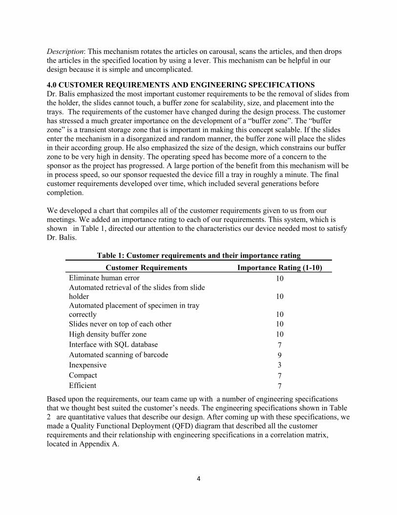
4.0 CUSTOMER REQUIREMENTS AND ENGINEERING SPECIFICATIONS Dr. Balis emphasized the most important customer requirements to be the removal of slides from the holder, the slides cannot touch, a buffer zone for scalability, size, and placement into the trays. The requirements of the customer have changed during the design process. The customer has stressed a much greater importance on the development of a “buffer zone”. The “buffer zone” is a transient storage zone that is important in making this concept scalable. If the slides enter the mechanism in a disorganized and random manner, the buffer zone will place the slides in their according group. He also emphasized the size of the design, which constrains our buffer zone to be very high in density. The operating speed has become more of a concern to the sponsor as the project has progressed. A large portion of the benefit from this mechanism will be in process speed, so our sponsor requested the device fill a tray in roughly a minute. The final customer requirements developed over time, which included several generations before completion. We developed a chart that compiles all of the customer requirements given to us from our meetings. We added an importance rating to each of our requirements. This system, which is shown in Table 1, directed our attention to the characteristics our device needed most to satisfy Dr. Balis.
Table 1: Customer requirements and their importance rating
Customer Requirements Importance Rating (1-10) Eliminate human error 10 Automated retrieval of the slides from slide holder 10 Automated placement of specimen in tray correctly 10 Slides never on top of each other 10 High density buffer zone 10 Interface with SQL database 7 Automated scanning of barcode 9 Inexpensive 3 Compact 7 Efficient 7
Based upon the requirements, our team came up with a number of engineering specifications that we thought best suited the customer’s needs. The engineering specifications shown in Table 2 are quantitative values that describe our design. After coming up with these specifications, we made a Quality Functional Deployment (QFD) diagram that described all the customer requirements and their relationship with engineering specifications in a correlation matrix, located in Appendix A.
5��
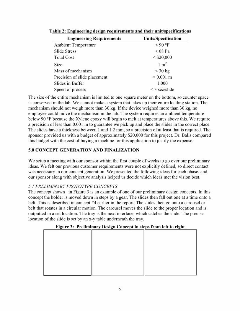
Table 2: Engineering design requirements and their unit/specifications Engineering Requirements Units/Specification
Ambient Temperature < 90 °F Slide Stress < 68 Pa Total Cost < $20,000 Size 1 m2 Mass of mechanism < 30 kg Precision of slide placement < 0.001 m Slides in Buffer 1,000 Speed of process < 3 sec/slide
The size of the entire mechanism is limited to one square meter on the bottom, so counter space is conserved in the lab. We cannot make a system that takes up their entire loading station. The mechanism should not weigh more than 30 kg. If the device weighed more than 30 kg, no employee could move the mechanism in the lab. The system requires an ambient temperature below 90 °F because the Xylene epoxy will begin to melt at temperatures above this. We require a precision of less than 0.001 m to guarantee we pick up and place the slides in the correct place. The slides have a thickness between 1 and 1.2 mm, so a precision of at least that is required. The sponsor provided us with a budget of approximately $20,000 for this project. Dr. Balis compared this budget with the cost of buying a machine for this application to justify the expense.
5.0 CONCEPT GENERATION AND FINALIZATION
We setup a meeting with our sponsor within the first couple of weeks to go over our preliminary ideas. We felt our previous customer requirements were not explicitly defined, so direct contact was necessary in our concept generation. We presented the following ideas for each phase, and our sponsor along with objective analysis helped us decide which ideas met the vision best.
5.1 PRELIMINARY PROTOTYPE CONCEPTSThe concept shown in Figure 3 is an example of one of our preliminary design concepts. In this concept the holder is moved down in steps by a gear. The slides then fall out one at a time onto a belt. This is described in concept #4 earlier in the report. The slides then go onto a carousel or belt that rotates in a circular motion. The carousel moves the slide to the proper location and is outputted in a set location. The tray is the next interface, which catches the slide. The precise location of the slide is set by an x-y table underneath the tray.
Figure 3: Preliminary Design Concept in steps from left to right
6��
Our preliminary prototype concepts revolved around sorting twenty slides. The slides were supposed to have predestined locations. The concepts with this assumption used many of the same preliminary pieces, such as carousels and belts. The rest of the design concepts from this generation are in Appendix C. 5.2 REFINED PROTOTYPE CONCEPT Our preliminary concept ideas did not consider some crucial factors that were later stipulated by our sponsor. Our sponsor envisioned the use of an end-effector mechanism that could individually pick up the slides from the holder and place them in a temporary location, i.e. a buffer zone, and eventually fill a tray with slides. These new constraints required us to come up with a completely new set of design concepts to meet our customer’s goal. Figure 4 shows an example of the concept for the prototype.
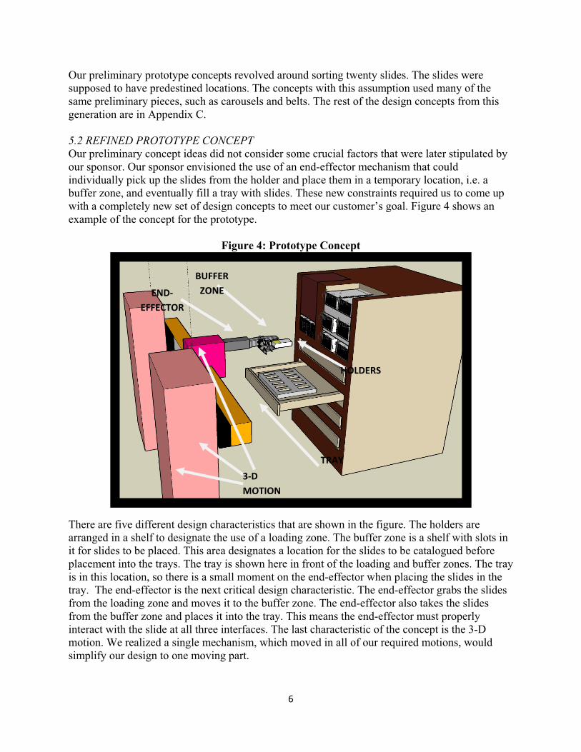
Figure 4: Prototype Concept
There are five different design characteristics that are shown in the figure. The holders are arranged in a shelf to designate the use of a loading zone. The buffer zone is a shelf with slots in it for slides to be placed. This area designates a location for the slides to be catalogued before placement into the trays. The tray is shown here in front of the loading and buffer zones. The tray is in this location, so there is a small moment on the end-effector when placing the slides in the tray. The end-effector is the next critical design characteristic. The end-effector grabs the slides from the loading zone and moves it to the buffer zone. The end-effector also takes the slides from the buffer zone and places it into the tray. This means the end-effector must properly interact with the slide at all three interfaces. The last characteristic of the concept is the 3-D motion. We realized a single mechanism, which moved in all of our required motions, would simplify our design to one moving part.
END�EFFECTOR�
BUFFER�ZONE�
TRAY
3�D�MOTION
HOLDERS�

7��
6.0 DESIGN CHARACTERISTICS AND ANALYSIS The five mechanical characteristics of our design from the previous section needed finalization. The electrical and programming parts of our design are also included in this section We decided to take a systematic approach to define how we would achieve all of our goals with engineering analysis and Pugh charts. 6.1 END-EFFECTORThe end-effector is a critical part of the device. It is the part that interacts directly with the slide at every interface. 6.1.1 Concept selection We came up with three different ideas for the end-effector; caliper, suction cup, and vacuum arm. We developed a criterion in selecting our end-effector. The criterion is shown in the form of a Pugh chart in table 3.
Table 3: End-effector Pugh chart
Evaluation Criteria Options
Caliper Vacuum SuctionCup
Grab from atop - ++ + Exterior machinery 0 - + Grip easily from buffer zone + - -- Requested by sponsor + 0 0
Total 1 0 0 The end-effector would benefit from a grab from atop approach. This would allow the mechanism to place the slide in the tray before being released. The vacuum arm and the suction cup would perform very well in this operation, while the caliper grabs the slide from the side. This means the slide must be dropped into place. All three of the devices would require some sort of external machinery. The caliper needs a very small linear actuator or gripper from a kit. The suction cup is the size of a pen and has a built in vacuum. The vacuum is strong enough to carry it, but we are not sure it will hold the slide in conditions with large accelerations. The vacuum arm would provide us the required force to prevent the slide from slipping, but it could require a decently large machine to generate this suction. The suction cup and vacuum arm require a large enough spacing of the slides in the loading and buffer zone for them to grab from the top. This characteristic directly conflicts with our customer requirement of a very high density buffer zone. Our sponsor also requested that our end-effector be in the form of a caliper as well. It is these reasons we decided to develop a mechanical gripper that resembled a caliper.
8��
6.1.2 Gripper design The design of a robotic end-effector is extremely crucial in any application and is especially important in ours. This is primarily due to the high precision of positioning and maneuverability of the gripper so that it is capable of picking up slides individually from the highly dense buffer region. There are several types of robotic manipulators or end-effectors that are readily available in the market, however, our application required a very specific type which limited our search.
6.1.2.1 Design Requirements & Constraints: Given the specificity of our application of handling slides with relatively high precision, there were several design requirements that needed to be met.
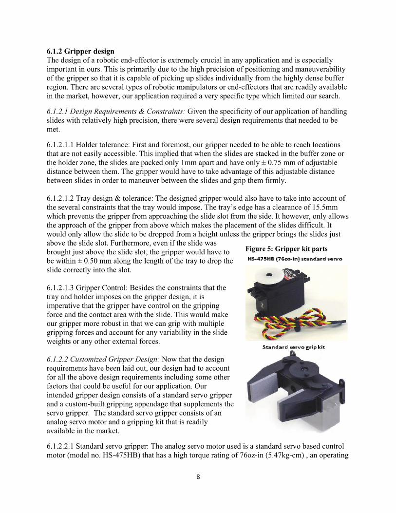
6.1.2.1.1 Holder tolerance: First and foremost, our gripper needed to be able to reach locations that are not easily accessible. This implied that when the slides are stacked in the buffer zone or the holder zone, the slides are packed only 1mm apart and have only ± 0.75 mm of adjustable distance between them. The gripper would have to take advantage of this adjustable distance between slides in order to maneuver between the slides and grip them firmly. 6.1.2.1.2 Tray design & tolerance: The designed gripper would also have to take into account of the several constraints that the tray would impose. The tray’s edge has a clearance of 15.5mm which prevents the gripper from approaching the slide slot from the side. It however, only allows the approach of the gripper from above which makes the placement of the slides difficult. It would only allow the slide to be dropped from a height unless the gripper brings the slides just above the slide slot. Furthermore, even if the slide was brought just above the slide slot, the gripper would have to be within ± 0.50 mm along the length of the tray to drop the slide correctly into the slot. 6.1.2.1.3 Gripper Control: Besides the constraints that the tray and holder imposes on the gripper design, it is imperative that the gripper have control on the gripping force and the contact area with the slide. This would make our gripper more robust in that we can grip with multiple gripping forces and account for any variability in the slide weights or any other external forces. 6.1.2.2 Customized Gripper Design: Now that the design requirements have been laid out, our design had to account for all the above design requirements including some other factors that could be useful for our application. Our intended gripper design consists of a standard servo gripper and a custom-built gripping appendage that supplements the servo gripper. The standard servo gripper consists of an analog servo motor and a gripping kit that is readily available in the market.
6.1.2.2.1 Standard servo gripper: The analog servo motor used is a standard servo based control motor (model no. HS-475HB) that has a high torque rating of 76oz-in (5.47kg-cm) , an operating
Figure 5: Gripper kit parts

9��
speed of 0.18s/60 degrees and a weight of only 1.52oz (~45g). Furthermore, the servo motor operates between 4.8VDC and 6VDC and hence can be powered by the parallel port via the computer.
6.1.2.2.2 Gripper kit: The gripping kit is an injection molded gripper that translates the rotational servo motor motion into a parallel gripping motion. Our design shall utilize this mechanism and supplement it with a gripping appendage for the overall gripper design. Figure 5, to the right, shows the gripping kit along with the analog servo that powers the parallel grips.
6.1.2.3 Custom-built gripping appendage: The gripping appendage is designed to meet the design constraints as explained above. The tall reach of the gripper appendage avoids the side walls of the tray and brings the slides just above the slide slot before being dropped. The short lower lip is designed for convenient release of the slide and the longer upper lip is designed for improved guidance of the gripper towards the slide holder zone or the buffer zone. One other advantage of the lower lip is its ability to flush against the finger groove to bring the slide extremely close to the tray. Theoretically this would also allow us to pick the slides from the tray, if necessary. Furthermore, the thick zone of the gripper appendage which interfaces with the parallel ends of the gripping kit helps reduce the minimum gripping distance between the parallel ends and brings the two appendages very close to each other and its gripping end.
Figure 6: Gripper appendage design
Parallel grippingends
1.25�
25�mm
20 mm
38.75�mm24
mm
8.75m
m7.5
mm
0.75�
0.75�
Upper
Lower

10��
Figure 6 shows the gripping appendage and its interface with the parallel gripping ends of the grip kit. The height of the lower appendage is 24mm which gives enough room between the gripping ends and the protruding tray ends. The thicknesses of the gripping appendage can be varied based on the desired grip kit dimensions whose dimensions need to be measured. The grip kit has been ordered and is currently on transit. The distance between the upper and lower lip of the gripping appendage has been set to 1.25 mm so that the slide can fit in and the gripper can subsequently grip the slide by controlling the servo.
The gripping appendage will be manufactured out of either Polypropylene or Stainless Steel, both chemically resistant materials. The appendage shall be made out of one single block of material to retain its structural properties and prevent any chances of cracking at crevices. Based on our analyses on gripping force we realized that stainless steel would be better especially since the flexing of the gripping appendage would be less significant. Polypropylene, on the other hand would provide a better surface interfacing between the glass slide and the relatively rough plastic surface as opposed to stainless steel. However, we intend to test both materials for gripping purposes for design optimization.
The figures in Appendix F show how the gripper shall place individual slides in the slide slots of the tray by avoiding its tall edges.
6.2 LOADING AND BUFFER ZONE
6.2.1 Initial design characteristics We designed a rack to be used for the buffer and loading zone. This design is shown here in figure 7.
Figure 7: Rack made from holders

11��
6.2.1.1 Buffer Zone: The rack shown above is mostly composed of the buffer zone. A distinct characteristic of this design is the use of the Leica slide holders, shown here in black. They are chosen because the slides come out of the cover slipper in this holder, and we felt it would be a good idea to use the same interface throughout the process. A dimension analysis of the Leica holders is provided in Appendix G. The Leica holders have a hole on one side. This hole provides a surface to lock the holder into place. Motion in all directions is constrained by the snap hole, so the holder will not move during the process. The holders are stacked on top of each other in a shelf like design to provide a stable and space efficient structure. 6.2.1.2 Loading Zone: The loading zone is only the top right part of the rack, underneath the yellow piece. The loading zone has a top that can be removed. This provides the user an angle to remove the empty holders and fill the loading zone with new holders for sorting. The loading zone contains forty slides because this was the figure given to us for prototype verification. 6.2.2 Initial design analysis 6.2.2.1 Dimension Analysis: The rack is design to hold a buffer zone for the mechanism. The quantity of slides required, 1000, in this buffer zone was designated by our sponsor. We performed a dimensional analysis using the holders as our base unit to design the rack. The holder is roughly 3.5 centimeters wide and 6.8125 centimeters tall, when placed in the position shown in figure 7. The analysis provides a table of possible rack dimensions. Each rack formation has a corresponding rows and holders per row. The amount of rows multiplied by the holders per row, equals the holders in each formation. Since there are 20 slides per holder, this is a systematic way of verifying the amount of slides the rack can hold in various configurations. This information is shown in table 4.
Table 4: Dimension analysis of the rack Width (in) Height (in) Holders / row Rows Holders Total Slides12 6 8 2 16 320 12 10 8 3 24 480 12 12 8 4 32 640 16 6 11 2 22 440 16 10 11 3 33 660 16 12 11 4 44 880 16 16 11 5 55 1100 20 6 14 2 28 560 20 10 14 3 42 840 20 12 14 4 56 112020 16 14 5 70 1400 20 20 14 7 98 1960
The table shows a rack with a width of 20 inches and a height of 12 inches will hold 1,120 slides. A rack with these dimensions can contain four rows of holders and with fourteen holders next to each other in each row. The design will require a total of fifty six holders from Leica. Dimensions of the entire rack are provided in a detailed description in Appendix I.1. The dimensions found here will determine the size of the three-dimensional motion device. The end-effector attached to the motion mechanism must be able to reach all of the slides in the rack, so the mechanism will be at least this size. The other dimension not described in this analysis for

12��
the three-dimensional motion mechanism has a requirement of 300 mm. This is enough to cross over the 207 mm wide tray, which is placed in front of the rack as shown in figure 7, and retrieve the 75 mm long slide from the rack itself. 6.2.2.1 Mechanical Analysis: The materials we were recommended for the construction of this rack design were Polypropylene and Delrin. These materials were chosen due to their chemical resistance to the chemical in the adhesive on the slides, Xylene. A static analysis of the rack is required to guarantee structural stability. A static analysis was performed on a rack with the configuration chosen in table 4. The analysis made the assumption of a full rack with all 1,120 slides in place to test extreme conditions. The details of this analysis are shown in Appendix I.2 The analysis showed a safety factor of 19.42 for Polypropylene and 17.40 for Delrin. We conclude either material is satisfactory for this application. 6.2.3 New rack design 6.2.3.1 Design characteristics: The previous rack described in the previous section became too expensive, when we were informed of the price of the Leica slide holders. The slide holders cost over fifty dollars apiece. The previous design required fifty six holders, which would make the rack cost over $2,800. We decided to manufacture our own rack. A picture of the rack design is shown in figure 8.
Figure 8: Final rack design with slides in place
The design shown above is chosen for its simplicity. It is made up of several columns lined up next to each other. The columns are to be connected by threaded rods at the top and bottom. The white bars will be manufactured from one sheet of material.
6.2.3.2 Design dimensions: The height of each slot is 2 mm. This is larger than the Leica holders to give ourselves a larger clearance, when placing the slides into the rack. The 2mm slots will be spaced 2 mm apart in the vertical direction, this displacement will ensure no complications in manufacturing. The depth of each slot is to be 50 mm. This value matches the depth of each slot in the Leica holder, and it will prevent the slides from falling out, when placed in the vertical position. The columns of the rack are spaced slightly more than 25 mm apart, the width of a

13��
slide. This gives a little extra clearance horizontally for the mechanism to place the slides in the rack. The diameter of the threaded rod is a quarter in and should be sufficient for support. A technical drawing with more detailed dimensions of the design is provided in Appendix I.3.
6.2.3.1 Design manufacturing: The design material will be milled out line by line from a large piece of material with a 2 mm drill bit, to provide the prescribed 2 mm clearance for each slide slot. Each 2 mm pass will be spaced out by 2 mm as described earlier to prevent material deformation in the milling process. The procedure will be repeated for each side. This will give the material the appearance shown in the middle columns of the rack. The depth of each slot will be 4 mm on each side to give an ample gripping surface. The long piece of material will then be cut into 50 mm wide pieces on a band saw.
6.3 CARTESIAN ROBOTIC SYSTEMCartesian motion can be achieved by the means of three linear actuators that are orthogonally assembled relative to each other. For our application specifically, it can be used to actuate the gripper in 3D.
6.3.1 Design requirements The chosen Cartesian system had to accommodate for several constraints that were set by our sponsor. Attaining speeds of 20 inches per second, and loading an entire tray with slides within 1-2 minutes were highly critical requirements that had to be met. Furthermore, using RS-232 as a host-computer interface was also important as it made the control of the mechanism easier via the Linux computer. The ability to pick up individual slides that were placed within 1mm of each other also had an immense bearing on our search primarily due to the precision of the whole mechanism. The desired accuracy of the system had to achieve an accuracy of 500um at most and a repeatability of 100um at most. 6.3.2 Design specifications After an exhaustive and careful search, OEM dynamics was found to be the ideal vendor for our prototype. The use of Animatics motors (SM2316 DT) with a rapid dynamic response was determined to meet each of the above mentioned constraints. The ready availability of this motor in our lab allowed us to test it out and prepare ourselves for the control of the motors well before the entire system is delivered to us. It is also important to note that the communication protocol takes place over RS-232 via simple acceleration, velocity and position commands each of which have been previously programmed. The actuators have a displacement per revolution up to 12.5mm/revolution, which according to our calculations will provide the required speed to fill a tray completely in approximately 1-2 minutes. The price for the entire set of 3 linear actuators including the required motors was approximately $9,000, which fall well within the sponsor’s budget. The strokes chosen to achieve the required slide capacity, are 574mm in the X axis (Horizontal plane), 400 mm in the Y axis (Vertical plane), and 300 mm in the Z axis. The rationale behind such a configuration has been explained in Table 4. The Z axis is 300 mm to provide adequate motion from the tray edge up to the rack. 6.3.3 Design components

14��
This is a description of all of the components that make up the Cartesian robotic system. It is compiled of three linear actuators, which are powered by servo motors. Here is a detailed description and analysis of each component. 6.3.3.1 Animatics Motor (SM2316 DT): The Animatics motor (SM2316 DT) chosen for our application has specifications that are listed in table 5. The encoder resolution of the motors is given to be 4,000 counts per revolution which would allow them to achieve a theoretical translational resolution of 3 �m. It has a top speed of 5,200 RPM, which allows the belt driven actuators to achieve high speeds of up to 700mm/s based on the pitch per revolution.
Table 5: Motor Specifications for the Animatics Motor SM2316DT
Specification Rating Continuous torque 0.4 (N.m)
Peak torque 0.79 (N.m) Torque constant 0.8 (N.m/amp)
Nominal continuous power 0.11 (KW) Top speed 5,200 (RPM)
Voltage constant 9.08 (V/krpm) Winding resistance 0.74 (Ohms) Encoder resolution 4,000 (Counts/rev)
Rotor inertia 0.727 (Kg-m) Shaft diameter 0.635 (cm)
Weight 0.61 (Kg) Length 5.8 (cm) Width 5.74 (cm)
6.3.3.2 X axis (HLD 60 with twin external rails): The X axis motion actuator was chosen to be enhanced with twin external rails because it will be carrying the entire weight of the other linear actuators including the gripper. The total force from weight acting on this actuator is around 90 N (~9kg). Although, the maximum displacement/rev could be 12.5 mm/rev, the engineers at the
Figure 9: Animatics 2316DT
15��
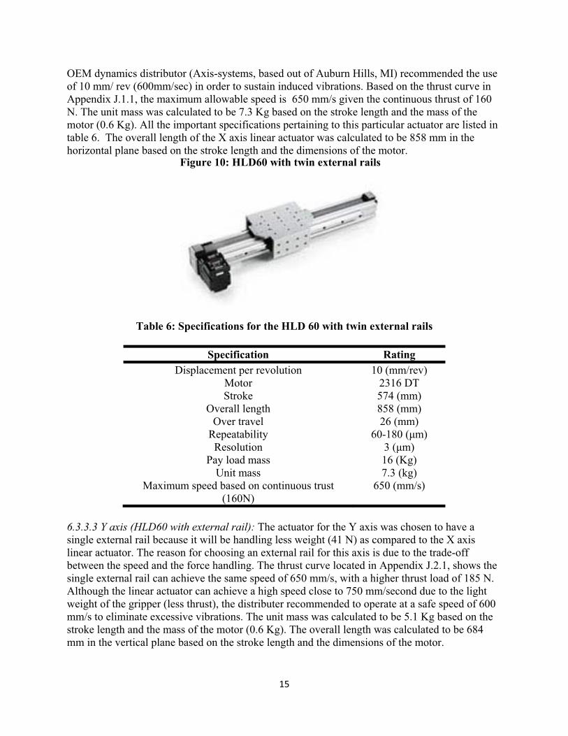
OEM dynamics distributor (Axis-systems, based out of Auburn Hills, MI) recommended the use of 10 mm/ rev (600mm/sec) in order to sustain induced vibrations. Based on the thrust curve in Appendix J.1.1, the maximum allowable speed is 650 mm/s given the continuous thrust of 160 N. The unit mass was calculated to be 7.3 Kg based on the stroke length and the mass of the motor (0.6 Kg). All the important specifications pertaining to this particular actuator are listed in table 6. The overall length of the X axis linear actuator was calculated to be 858 mm in the horizontal plane based on the stroke length and the dimensions of the motor.
Table 6: Specifications for the HLD 60 with twin external rails
Specification Rating Displacement per revolution 10 (mm/rev)
Motor 2316 DT Stroke 574 (mm)
Overall length 858 (mm) Over travel 26 (mm)
Repeatability 60-180 (�m) Resolution 3 (�m)
Pay load mass 16 (Kg) Unit mass 7.3 (kg)
Maximum speed based on continuous trust (160N)
650 (mm/s)
6.3.3.3 Y axis (HLD60 with external rail): The actuator for the Y axis was chosen to have a single external rail because it will be handling less weight (41 N) as compared to the X axis linear actuator. The reason for choosing an external rail for this axis is due to the trade-off between the speed and the force handling. The thrust curve located in Appendix J.2.1, shows the single external rail can achieve the same speed of 650 mm/s, with a higher thrust load of 185 N. Although the linear actuator can achieve a high speed close to 750 mm/second due to the light weight of the gripper (less thrust), the distributer recommended to operate at a safe speed of 600 mm/s to eliminate excessive vibrations. The unit mass was calculated to be 5.1 Kg based on the stroke length and the mass of the motor (0.6 Kg). The overall length was calculated to be 684 mm in the vertical plane based on the stroke length and the dimensions of the motor.
Figure 10: HLD60 with twin external rails

16��
Table 7: Specifications for the HLD 60 with single external rails
Specification Rating Displacement per revolution 10 (mm/rev)
Motor 2316 DT Stroke 400 (mm)
Overall length 684 (mm) Over travel 26 (mm)
Repeatability 60-180 (�m) Resolution 3 (�m)
Pay load mass 18 (Kg) Unit mass 5.1 (kg)
Maximum speed based on continuous trust (185N) 650 (mm/s) 6.3.3.4 Z axis (HLD60 with internal rollers): The linear actuator for the Z axis was chosen with an internal roller because it will sustain the least load (weight of gripper), which is estimated to be 0.5 Kg. The OEM manufacturer specified the thrust curve for the rollers and the single external rail to be the same. The overall length was calculated to be 584 mm based on the stroke length and the dimensions of the motor. The unit mass was calculated to be 3.84 kg based on the stroke length and the mass of the motor (0.6 Kg). The thrust curve located in Appendix J.3.1, predicts that the linear actuator could be driven at 650 mm/s at a thrust load of 185 N. We could achieve a very high speed close to 750 mm/s due to the low thrust load (light gripper), but the distributer recommended to operate the linear actuator at a safe speed of 600 mm/s. The overall dimensions of the XYZ Cartesian assembly are less than 1 cubic meter, and hence the mechanism is compact as specified by the sponsor.
Figure 11: HLD60 with single external rail
Figure 12: HLD60 with internal rollers

17��
Table 8: Specifications for the HLD 60 with internal rollers
Specification Rating Displacement per revolution 10 (mm/rev)
Motor 2316 DT Stroke 300 (mm)
Overall length 584 (mm) Over travel 26 (mm)
Repeatability 60-180 (�m) Resolution 3 (�m)
Pay load mass 18 (Kg) Unit mass 3.84 (kg)
Maximum speed based on continuous trust (185N) 650 (mm/s) 6.3.4 Cartesian system force analysis A force analysis is required to ensure safety and security of the system during operation. It is an analysis that is customized to this system.
6.3.4.1 Weight of units: The weight applied on the X axis linear actuator (90 N) is the sum of the weight of the Y axis, Z axis and the gripper. The weight applied on the y axis (41 N) is the sum of the weight of the Z axis and the gripper. The weight applied on the Z axis (5 N) is the weight of the gripper.
Table 9: Weights of the individual linear actuators
Linear actuator Weight HLD60 with dual external rails 71 N
HLD60 with single external rails 49 N
HLD 60 with internal rollers (Z axis) 36 N 6.3.4.2 Force and moment analysis: The force analysis was done by assuming that the unit mass acts at the center of mass. The forces and moments applied are summarized in the following table. The load capacity and the moment capacity are specified by the vendor, and the calculations show that they applied loads and moments are lower than the load capacity and the moment capacity by a minimum safety factor of 2.
Table 10: Force analysis on each linear actuator
Axis Load applied Load capacity Moment applied Moment Capacity
X axis 90 N 3000 N 6 N.m 89 N.m
Y axis 41 N 460 N 6 N.m 12 N.m
Z axis 5 N 35 N 0.5 N.m 2 N.m
18��
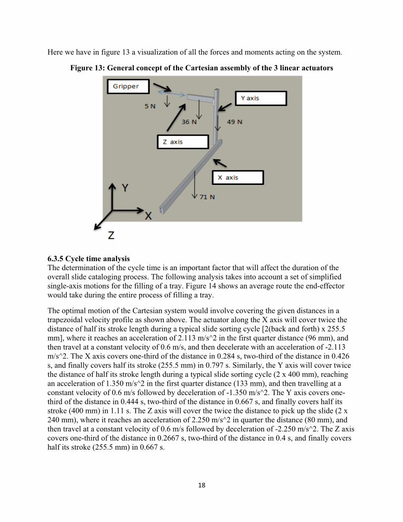
Here we have in figure 13 a visualization of all the forces and moments acting on the system.
Figure 13: General concept of the Cartesian assembly of the 3 linear actuators
6.3.5 Cycle time analysis The determination of the cycle time is an important factor that will affect the duration of the overall slide cataloging process. The following analysis takes into account a set of simplified single-axis motions for the filling of a tray. Figure 14 shows an average route the end-effector would take during the entire process of filling a tray.
The optimal motion of the Cartesian system would involve covering the given distances in a trapezoidal velocity profile as shown above. The actuator along the X axis will cover twice the distance of half its stroke length during a typical slide sorting cycle [2(back and forth) x 255.5 mm], where it reaches an acceleration of 2.113 m/s^2 in the first quarter distance (96 mm), and then travel at a constant velocity of 0.6 m/s, and then decelerate with an acceleration of -2.113 m/s^2. The X axis covers one-third of the distance in 0.284 s, two-third of the distance in 0.426 s, and finally covers half its stroke (255.5 mm) in 0.797 s. Similarly, the Y axis will cover twice the distance of half its stroke length during a typical slide sorting cycle (2 x 400 mm), reaching an acceleration of 1.350 m/s^2 in the first quarter distance (133 mm), and then travelling at a constant velocity of 0.6 m/s followed by deceleration of -1.350 m/s^2. The Y axis covers one-third of the distance in 0.444 s, two-third of the distance in 0.667 s, and finally covers half its stroke (400 mm) in 1.11 s. The Z axis will cover the twice the distance to pick up the slide (2 x 240 mm), where it reaches an acceleration of 2.250 m/s^2 in quarter the distance (80 mm), and then travel at a constant velocity of 0.6 m/s followed by deceleration of -2.250 m/s^2. The Z axis covers one-third of the distance in 0.2667 s, two-third of the distance in 0.4 s, and finally covers half its stroke (255.5 mm) in 0.667 s.

19��
AccelerationAcceleration
Displacement�Displacement
Displacement
Acceleration�
�2�(mm/�s^2)�
0.6�(m/�s)�
96�(mm)�
287(mm)�
191�(mm)�
1.3�(mm/s^2)
� 1.3�(mm/s^2)
0.6�(m/�s)
133�(mm)
133�(mm)267�(mm)
400�(mm)
Acceleration�
2.3�(mm/s^2)
�2.3�(mm/s^2)
0.6�(m/�s)
80�(mm)
80�(mm)80�(mm)160(mm)
240(mm)
0.3�(s)� 0.4�(s)� 0.8�(s)� 0.4�(s) 0.7�(s) 1.1�(s) 0.3�(s)� 0.4�(s)� 0.7�(s)
Figure 14: Velocity & acceleration profiling for cycle time determination
X axis motion profile Y axis motion profile Z axis motion profile
Assuming that it takes 0.5 s to pick up the slide by the gripper and place it in its correct location, the total cycle time can be calculated as 2 x (0.667+0.797+1.11) + 0.5 + 0.5 = 6s. In this case, the worst case scenario is chosen to pick up the slide and place it in the tray by traveling the furthest distance by moving in one axis at a time. The calculated cycle time predicts that the total time to load a tray is 2 minutes, which falls within our requirements. Furthermore, optimized solutions to picking up and placing slides can further improve tray filling speeds. Another optimization that can be done would involve simultaneous motion of the linear actuators to move between two points in the shortest distance. All these factors can significantly reduce the overall cycle time and hence would be an important tweaking parameter during the testing phase.
6.3 HARDWARE & SOFTWARE ARCHITECTURE
To build a robust mechatronic system, implementation of the software architecture was crucial to the overall performance of the system. The fusion of the hardware and software ends should be necessary to bring about a complete robotic system such as ours. The system which contains switches, linear actuators, scanners and a gripper will require a strong software backbone to control all of it.
Velocity�
VelocityVelocity
2�(mm/�s^2)�
�
2�x�[240 (mm)]
2�x�[400 (mm)]

20��
6.3.1 Programming layout To have a structured program sequence for our mechanism, we decided to map out the various steps involved in the slide cataloging process. We took a logic based programming approach to designing the different steps in the lab automation process. The figure in Appendix K.2 illustrates the different steps involved in the programming sequence all the way from initialization of the mechanism using the NPN Limit switches to the final steps of post processing sequences where the buffer zone is emptied based on which tray is currently being filled. The main hub is the Linux computer which interfaces with the several switches and barcode reader. Some of the conditional statements can be checked using active feedback from either switches or the barcode reader.
6.3.2 Master controller The main controller/programmer that shall be used in our application will be the PM-LX-800 which is a PC/104 form factor highly integrated embedded computer. The PM-LX-800 is particularly suitable for low power and fan-less applications. It boasts a large set of on-board connectors that we shall utilize for our application. Some of the important connectors that we shall utilize are a Parallel port connector for general purpose I/O communication, 2 RS-232 connectors for serial communication, a USB connector, a VGA connector for visual feedback and a PCI-104 connector for further addition of ports if necessary. The embedded computer is powered by an AMD Geode LX 800 running at 500MHz with 512MB DDR333MHz RAM. The small form factor (90mm x 96mm) of the computer makes it a suitable product for our application, given the space constraints.
The computer shall be powered by a Linux distribution of slackware that is burned onto a 512 MB compact flash card. The use of non-GUI based interface makes the computer run at much better speeds and provide enough memory for running our program.
6.3.3 Programming language Our application of lab automation is based on the very same fundamentals of logic based programming. Due to the time constraints of this project, we decided to choose a programming language that would accommodate our specific needs. After some careful consideration and some analysis via Pugh charts located in Appendix K, we decided to choose Python as our main programming language.
Python is an open-source, dynamic, object-oriented programming language that has recently won the hearts of several novice programmers. Its intuitive scripting language provides the power of programming in an easier package and allows rapid prototyping of programs, which is very crucial to us. It is critical to have our XYZ Cartesian system programmed quickly to be able to have a working prototype before the design expo. Python generally has a much faster learning curve as opposed to C/C++ and this also made it a promising language to work with. Furthermore, Python runs on multiple platforms, including Windows, Mac and Linux more importantly. Python also has extensive libraries and modules available for free on-line which may be utilized for our advantage. One such module that shall be used is the serial and parallel port modules that allow the python script to relay commands to and from the serial/parallel ports. Another advantage of python is its extensive on-line support for debugging and interfacing

21��
which will be greatly appreciated during the programming phase. All these factors make Python a very suitable candidate for our programming purposes.
6.3.4 Controlling the system Controlling our complete Cartesian system involved several preliminary steps including initialization and setting homing positions before any sequential motion can be produced. The following steps were taken to initialize the complete system before the sequencing programs could be run. Each subsection contains a python script (Appendix M) that shall be referred to.
6.3.3.1 Motor Communication: The SmartMotor uses an asynchronous serial interface often described as a "three wire implementation of RS232." The baud rate was set to 9600bps which is also the default communications. When the RS232 is in the idle state (waiting to transmit a message) it rests in the high (on) state. When a character is to be transmitted the TxD line is brought low for a carefully defined period of time, the time period of the start bit is a function of the BAUD rate. This low state is called the start bit. Immediately following the start bit are a number of data bits. The SmartMotor must use 8 data bits, and this is the meaning of the "8" in the string "8-N-1."
6.3.3.2 Auto-Homing Sequence: Once the motors are turned on, they lose the memory of their current position. This is very much undesirable and hence should be corrected every single time the motors are turned on. For this purpose, we used the limit switches to trigger the motor to execute its 'home' subroutine. This means that every time the motors are turned on, they look for the limit switches by traversing over its axis until it is found. Once the limit switch falls immediately under the linear stage, the motors automatically sets its current position to be its home position (P=0). The motors can only run this homing subroutine once the homing program is loaded on each individual motors. This is done via the Smart Motor Interface (SMI) program provided by Animatics. The homing subroutine can be found on the Animatics website under the Tech Support > Sample Programs link. Once the program is individually loaded on the motors via the SMI program, the motors shall home itself as soon as they are turned on.
6.3.3.3 Daisy Chaining:�Since the motors are to be placed on a single RS-232 communications line, they must be set up properly to avoid any communication errors. For our system that communicates via RS-232, all the motors must be initialized to ECHO mode. While in ECHO mode, all data reaching a motor's received port will be echoed" back out its transmit port. Since RS-232 serial lines must be daisy-chained together, the motors must be in ECHO mode to work properly. An RS-232 chain of motors can be addressed from a host or master without the motors containing programs. It is important to review the daisy chaining electrical connections and ensure that it is working before this sequence can be run.
6.3.3.4 Motor initialization: While in a unique daisy chain setup, the motors cannot differentiate between commands sent to specific motors unless the data sent are addressed to specific motors. Therefore, an initialization sequence needs to be run to set each individual motor to a unique address. This will allow the host PC, the linux computer in our case, to communicate to an individual motor as opposed to communicating to every motor while in ECHO mode. This sequence is run as follows.
22��
(dec128)ECHO_OFF (dec128)SADDR1 (dec129)ECHO (dec129)SLEEP (dec128)SADDR2 (dec130)ECHO (dec130)SLEEP (dec128)SADDR3 (dec131)ECHO (dec131)SLEEP (dec129)WAKE (dec130)WAKE (dec131)WAKE
The python script that relays this set of commands is shown in Appendix M.2.
6.3.3.4 Gripper Control: The analog servo required to be controlled by sending a pulse width modulated signal of different duty cycles. While sending the signals at approximately 400 Hz, a duty cycle of 50% would open the gripper to our required amount (~ 1cm clearance between the two appendages). A duty cycle of 75% corresponded to closing in the distance between the gripping appendages enough to produce a firm grip on the slides. We decided to send the PWM signal via the parallel port of our computer and power the analog servo via the 5V power supply of the computer. The yellow cable from the servo (signal pin) was connected to the D1 pin of the parallel port. Since the timer within the computer was not capable of producing the desired duty cycle at 400Hz, we chose to send out multiple “Turn on pin 1” commands to meet our requirements.
To produce a 400Hz PWM signal, a time period of 2.5ms was required. Thus to produce a 50% duty cycle, the D1 pin needs to be turned on for 1.25ms and turned off for the next 1.25ms. Since this could be accomplished using C code, a simple program was written to turn on pin D1 on the parallel port multiple times to recreate the desired PWM signal. The resulting compiled binary file was executed and stopped (‘killed’) in the linux shell in the python sequence script. See gripSlide, killGrip, releaseGripAboveSlide and placeSlide functions in the python sequence script for more on gripping implementation in python.
6.3.3.4 Slide placement sequence preface: Once the motors are initialized and assigned unique addresses, the python script shall output if there are any syntax flags. It is always a good practice to make sure that the motors are not flagged so that they can communicate via serial port. If the motors are flagged, they shall not respond until the flags are reset by sending a ‘ZS’ command to the flagged motor. A more extensive command set is available on the Animatics website for more effective communication.
Before the sequence is run, it is important to know that the script uses the COM1 ‘/dev/ttyS0’ to communicate to the motors and COM2 ‘/dev/ttyS1’ to communicate to the barcode reader.
23��
To produce a sequence of motions, it was important to complete one axis motion before we start on the other. For this purpose, the motors reported their velocities every second so that we know when to start the other motions. A specific python function was written for this purpose and can be seen in Appendix M.2 under the waitOnMotor function. Thus while writing to the motors sequentially, the function writeToMotor implements the waitOnMotor function so that the writeToMotor can be sent to the motors one after the other, and the motions of the slides will only occur one at a time. The RV function in the python script reports the velocities as mentioned above.
Several other functions were used to accomplish specific motion regimes such as moveToBuffer, moveToTray, moveToHolder, moveToGrip, placeSlide. Since each of these motions are quite apparent from their names, they use the previous writeToMotor to move to their corresponding positions by addressing specific motors. Motors m1, m2, m3 refer to X, Y and Z axis respectively and mAll corresponds to global which implies that it is referring to all the motors at once.
Some of the initializations occurring at the beginning of the python script refer to the calibrated positions of the motors. The positions of the first and last slides in the holder, buffer and tray are initially calibrated so that each individual location of the slots can be determined via interpolation.
6.3.3.5 Slide placement sequence: Initially all the flags that may have occurred during initialization or previous sequences are cleared using the clearFlags functions and they are sent to each motor. All the buffered communication via the serial port is also flushed so that fresh data can be read.
clearFlags(m1)�clearFlags(m2)�clearFlags(m3)��ser0.flushInput()�print�'Clearing�flags...'��The following code waits for keyboard input before the sequence is started. This was critical to prevent any errors or mishaps from occurring. The gripSlide() and killGrip() functions are run to make sure that the gripper starts from the closed position. raw_input('Start�sequence....')�gripSlide()�killGrip()� The following snippet makes sure that the sequence runs continuously for each of the 20 slides in the holder zone. The first sequence moves to the holder zone based on which slide is currently being processed. It then moves inwards to grip the slide being processed. Once this is complete, the gripper moves out of the holder zone and sequentially reads the barcode embedded with the final slide location i.e. zone, column and row.
24��
while�1:�� for�slide�in�range(1,21):�� � print�'Processing�slide�',�slide�� � if�holder1[slide�1]:�� � � moveToHolder(slide)�� � � moveToGrip('holder')�� � � zone,var1,�var2�=�readSlideLoc()� The following snippet decides where to move the slide based on the barcode information that is previously read. If the slide belongs to the tray, then it would move towards the tray and place the slide. Since the placing of slides are different for different zones, the placeSlide function takes into account of this and acts accordingly. If the slide belonged to the buffer zone, then the system would move it to the buffer zone and place it accordingly. � � � �� � � if�zone�==�'tray':� � � #var1�=�col,�var2�=�row�of�tray�� � � � moveToTray(var1,var2)�� � � � placeSlide(zone)�� � � elif�zone�==�'buffer':� � #var1�=�col,�var2�=�row�of�buffer�� � � � moveToBuffer(var1,var2):�� � � else:�� � � � print�‘DEBUG�##’� �

25��
6.4 ELECTRICAL SYSTEM
This section explains all of the components of our electrical system. The electrical system has been mapped out into an overall scheme, so we can prepare for assembly ahead of time.
6.4.1 Electrical layout To have a thorough understanding of the electrical connections involved, we constructed an electrical layout that outlines the different connections and voltages that the several sub-systems operate. The Cartesian system constituting of the 3 linear actuators will be powered by 3 separate power supplies (product) rated at 48V 10A max. The Linux computer that shall interface with the different subsystems is powered by a standard 110V supply via an AT power supply that can be bought readily off the market. The only other subsystem that requires power will be the gripper that operates at around 4.8VDC to 6VDC. Each of these power cords shall be zip-tied against the linear actuators so that it prevents any cord entanglements. Each of the micro-switches, optical switches, snap action switches are interfaced with the parallel port for general I/O communication. The 2D barcode reader will be attached just above the gripper with its cord connected to one of the RS232 ports on the Linux computer. The other RS232 port shall accommodate all the linear actuators involved in the Cartesian system. The first motor is connected to the computer via the RS232 port and the subsequent motors are connected to each other via daisy-chaining. It is important to note that each of the motors are in ECHO mode when the current configuration is implemented. Some other intended components would involve running a large red push-button for E-stop to the main power supply during emergency cases. A figure explaining this system in a visual representation is shown in Appendix L.
6.4.2 Electrical switch selection The electrical switches were chosen in specific locations for a reason. Appendix K.2, which describes the programming layout, identifies the need for four switches in the system. The switches must be selected for each implementation individually. The first switch in the system is an initialization switch. This switch is activated when the end-effector is at the home position. Since this application has to do with a precise location that does not move, a micro switch may be a good option. An optical switch may be over kill in this application. The second switch in the system is for identification of slides in the loading zone. This is a good opportunity for an optical switch. An optical switch can be mounted on the end-effector and scan down the holder, checking one at a time for slides. Since the slides are made of glass, we may also be able to calculate reflection of the optics as another way of identifying slides in the holder. Two other uses of a micro switch in our system involve part identification. This process identifies if a part is in position, such as the holder in the loading zone or the tray. These parts require correct positioning in two directions or the mechanism will be unable to perform properly. Thus both parts will require two switches, one for each direction. A final emergency switch that detects a human entering the system may be optic. The switch can generate an infrared line that will trigger an emergency stop if penetrated by the user.
6.5 MOUNTING AND FRAME
The success of our system hinges on knowing the exact locations of all of our components. If a component is in the wrong location, the end-effector will not be able to perform its duties properly. Also, the Cartesian system will be applying sudden and variable loads during

26��
operation. This system needs a mount for stability, or it will fall over in action. Our system also needs a protective shell around it to guarantee safety to the user. These three factors lead us to the design of our mount and frame system. 6.5.1 Mounting method We decided to use T-slotted extrusions as the basis for our frame. They are inexpensive and made out of 6105-T5 Aluminum. A visual of our frame is shown as a part of Figure 15. The extrusions are 900 mm because that is the largest exterior dimension in any direction, and we prefer to have a nice cube safe zone for appearance. The aluminum extrusions are connected at each intersection with a special L-bracket that is designed for the T-slotted extrusions. These brackets will be used to mount the rack and the Cartesian robotic system. 6.5.1 Frame A frame around the design is required for safety and user interface. We have decided to use plexi-glass to fill in the supports left by our mounts. McMaster provides a simple way to attach plexi-glass to their extrusions. One of the sides of the frame will be attached with a special hinge to allow the user to open and close the device, when accessing the holders or trays.
Figure 15: Full design assembled
Frame and Mount
Buffer and Loading Zone
TrayCartesian RoboticSystem

27��
7.0 TESTING METHODS
Here we have to explain the methods we will test our analysis and engineering. The tests performed will decide the success of our design.
7.1 GRIPPING TEST
The gripper is an essential part of this system. We must apply very strong accelerations to the end-effector to see if the gripping is strong enough to prevent any slippage. If the slides lips at all, the orientation will be off. We must find the acceleration that overcomes the friction in the gripper, so we are aware of our limits.
7.2 CYCLE TIME TEST
The team will perform several tests involving the validation of our cycle time. The team will fill the tray 15 different times with the slides in random positions. The time it takes to fulfill this task will be recorded and analyzed. We are looking for a cycle time of one minute, but the distribution of cycle times is important as well. If a certain scenario yields a cycle time of 4 minutes, the system should be altered. 7.3 PLACEMENT TEST
The accuracy of the placement is very important. To guarantee accuracy, the team will place a slide in each slot of the buffer zone 10 times from the home position. We will register any errors. The same process will take place for the twenty locations of the tray, but we will perform this process 20 times due to the placement’s increased difficulty.
7.4 SCANNING TEST
We need to ensure the barcode is scanned, or the system will not know what to do with the slide. This operation will also be repeated on a large scale, to guarantee its success. We will implant a back up process of how to retrieve the bar-code information if it is not initially provided.
8.0 PROJECT PLAN
Our team devised a project plan to structure the following steps that we need to take in order to complete our project. The following project plan involves an immediate plan of action required to assure that our team is on track with the agenda and upcoming deadlines. It includes the following tasks that were completed prior to Design Review 3 and our upcoming deadlines that need to be met prior to Design Review 4 and 5.

28��
8.1 TASKS COMPLETED FOR DESIGN REVIEW 3 1) Full Engineering Design Analysis 2) Ordered x-y-z table from OEM Dynamics in Auburn Hills, Michigan 3) Electronic components purchased for prototype testing 4) Ordered servo gripping kit, extrusions, brackets, and plexi-glass 5) Computer training from Dr. Kruger (October 23, 28 & 30) - Voltage to Digital Circuits - Computer setup 6) OEM Dynamics tour on November 6 in Auburn Hills, Michigan 8.2 TASKS COMPLETED FOR DESIGN REVIEW 4 & 5 8.2.1 Week of November 10 1) Begin and complete manufacturing of the rack 2) Gain familiarity with optical switches 3) Begin manufacturing the gripper appendage 4) Order extrusions, brackets, and plexi-glass
5) Begin preliminary sub-files programming 8.2.2 Week of November 17
1) Have preliminary sub-files programmed 2) Begin testing of devices 3) Acquire two dimensional bar codes 4) Complete the manufacturing process of the gripper appendage 5) Systems integration All of these components need to be completed in order to have a functional working prototype ready for the Design Expo on December 4, 2008. Table 3 contains the major deadlines we have set for the course of the project.
Table 11: Project plan implemented in our design
Date Description
September 11 & 15 University of Michigan Pathology Lab Tour with Ulysses Balis September 30 Design Review #1 – Problem Definition and Preliminary ConceptsOctober 16 Design Review #2 - Concept and Engineering AnalysisNovember 6 Design Review #3 – Final Design DevelopmentNovember 25 Design Review #4 – Prototype Review & ManufacturingDecember 4 Design Review #5- Design Expo

29��
December 9 Final Report Due Appendix B shows an in-depth view of our project schedule in the form of a Gantt chart. Here we have shown the important deadlines that outline our entire process throughout the semester.
9.0 MANUFACTURING AND ASSEMBLY
9.1 GRIPPER APPENDAGES
The gripper appendage required a certain type of manufacturing due to its shape and application. The shape of the appendages has several right angles. The right angles were important to the success of this design because the two appendage pieces are designed to fit snugly onto each other in the closed position. This led us to use the Wire EDM machine for manufacturing these parts. This machine uses electrical charges, which are sent through a thin brass wire, to melt the metal stock in a localized area. The machine defines its feed rate and electrical cutting settings automatically based on the write type, material type and thickness. The machining path was programmed into the machine using absolute coordinates in a G-code file. The machine we used in our lab unfortunately was not in optimal condition, as the beam and wire shown here in figure N.21 & N.22 (Appendix N) are not perfectly perpendicular. This offset left our parts crooked and would require the slides in the holder zone, buffer zone, and tray to be crooked as well to perform properly.
The Wire EDM’s inability to cut at a proper angle led us to use the Water Jet Cutter machine N.23 (Appendix N). The machine does not supply as nice of a finish around the edges, but it was able to complete the task in minutes as opposed to hours with the EDM. The Water Jet Cutter shoots sand and water at a very high velocity at the material in order to cut through the material. These settings along with feed rate were selected based on material type and thickness. The machining path was imported with a dxf file from our CAD drawings.
9.2 SYSTEM FRAME
We purchased several feet of T-slotted aluminum extrusions. The extrusions were measure out to the appropriate distances and cut with a band saw. The tolerances or surface finishes were not a high priority for the success of our design. After cutting the pieces each piece was attached to one another with L brackets and 1/4 x 20 screws. The screws attached the L-bracket to bolts that fit inside the slots of the extrusions. An example of this fixture is show here in figure N.9 & N.10 (Appendix N). These extrusions provided a sound structure for all of our subsystems to be mounted. Another two cross bars were placed on the back, so the linear slide system could be soundly held into place.
9.3 GRIPPER MOUNT

30��
The mount for the gripper was manufactured out of High Density Polyethylene. The pieces were created on a mill with multiple drill bits. Each piece was leveled on two sides to create straight edge, so proper zeroing could be performed. The holes were milled at a spindle rat of 800 RPM. The holes that connected the two separate pieces of the gripper mount were threaded, so a screw could keep the two pieces together.
9.4 BUFFER ZONE
The buffer zone was manufactured with a mill and band saw. The mill, which was programmed with G-code, cut 75 rows along one big piece of HDPE. This was done at a spindle rate of 600 RPM and a feed rate of 400 mm/min. This operation was performed on both sides of the large piece of ¾ inch thick HDPE. The mill bit used was had a diameter of 2mm. The cutting depth was 2.25mm to ensure enough clearance in placing the slide into the buffer zone. Once both sides were milled, the material was cut on a band saw into two inch slabs. This thickness is the depth of the buffer zone and provides enough stability to prevent slides from falling out. The slabs then had holes drilled into them and tapped, so L-brackets could attach them to the T-slotted extrusion frame.
9.5 HOLDER ZONE
The holder zone was manufactured out of Polypropylene with a thickness of a quarter inch. The material was band sawed then filed down to its appropriate dimensions. The back and bottom from were glued together, with cement for ease of manufacturing. The top of the box required some structure, which was supplied by the zinc plated stand offs. The standoffs were screwed in from the bottom. In order for the top to detach from the stand offs magnets were attached to the standoffs and bottom side of the holder zone cover. A picture of this design is shown here in figure N.6 & N.7 (Appendix N) even though it was not attached to the frame in the final prototype. A replacement to this design was implemented with a bar that allowed the holders to snap in and out of place. We mounted this bar to the side of the buffer zone with magnets and super glue.
10.0 DESIGN DISCUSSION
In this section, we will give an explanation of the standing of this project. The information supplied will cover possible short term improvements to the design along with long term direction, that will help meet all the customer requirements in full. 10.1 SHORT TERM
10.1.1 Gripper Mount The gripper device used in our device is quite small in size, so it can get into the small places of the holder, buffer zone tray. The problem with have a gripper appendage of this size is how it is
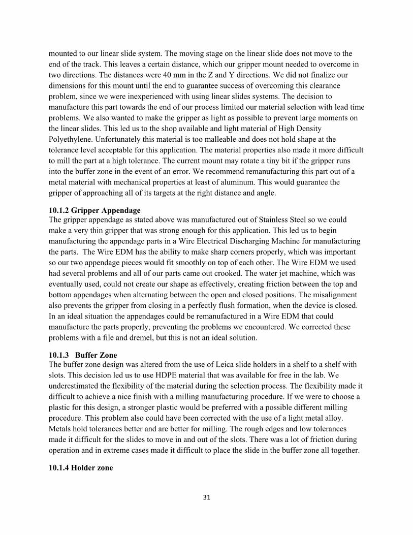
31��
mounted to our linear slide system. The moving stage on the linear slide does not move to the end of the track. This leaves a certain distance, which our gripper mount needed to overcome in two directions. The distances were 40 mm in the Z and Y directions. We did not finalize our dimensions for this mount until the end to guarantee success of overcoming this clearance problem, since we were inexperienced with using linear slides systems. The decision to manufacture this part towards the end of our process limited our material selection with lead time problems. We also wanted to make the gripper as light as possible to prevent large moments on the linear slides. This led us to the shop available and light material of High Density Polyethylene. Unfortunately this material is too malleable and does not hold shape at the tolerance level acceptable for this application. The material properties also made it more difficult to mill the part at a high tolerance. The current mount may rotate a tiny bit if the gripper runs into the buffer zone in the event of an error. We recommend remanufacturing this part out of a metal material with mechanical properties at least of aluminum. This would guarantee the gripper of approaching all of its targets at the right distance and angle.
10.1.2 Gripper Appendage The gripper appendage as stated above was manufactured out of Stainless Steel so we could make a very thin gripper that was strong enough for this application. This led us to begin manufacturing the appendage parts in a Wire Electrical Discharging Machine for manufacturing the parts. The Wire EDM has the ability to make sharp corners properly, which was important so our two appendage pieces would fit smoothly on top of each other. The Wire EDM we used had several problems and all of our parts came out crooked. The water jet machine, which was eventually used, could not create our shape as effectively, creating friction between the top and bottom appendages when alternating between the open and closed positions. The misalignment also prevents the gripper from closing in a perfectly flush formation, when the device is closed. In an ideal situation the appendages could be remanufactured in a Wire EDM that could manufacture the parts properly, preventing the problems we encountered. We corrected these problems with a file and dremel, but this is not an ideal solution.
10.1.3 Buffer Zone The buffer zone design was altered from the use of Leica slide holders in a shelf to a shelf with slots. This decision led us to use HDPE material that was available for free in the lab. We underestimated the flexibility of the material during the selection process. The flexibility made it difficult to achieve a nice finish with a milling manufacturing procedure. If we were to choose a plastic for this design, a stronger plastic would be preferred with a possible different milling procedure. This problem also could have been corrected with the use of a light metal alloy. Metals hold tolerances better and are better for milling. The rough edges and low tolerances made it difficult for the slides to move in and out of the slots. There was a lot of friction during operation and in extreme cases made it difficult to place the slide in the buffer zone all together.
10.1.4 Holder zone

32��
The holder zone of our design was a fixed box that allowed the Leica holders to be removed in and out for slide insertion. We manufactured this part, but we were unable to find the appropriate part to properly fasten the holders into place. A picture of this holder box is shown here to the right in figure N.6 & N.7 (Appendix N). We were forced to use an alternative solution that mounted the holders on the side of the buffer zone with magnets. The way the holders are currently mounted does not guarantee an exact position of the holders in every run, requiring a calibration process for every cycle. This can be corrected with a simple screw or snap pin to fasten the holders into place. We were unable to identify a part that could fit in time, as we became extremely occupied with the other components of our design. We also were unable to develop a permanent fastener to our trays. These components were supposed to be fixed in position with the use of electrical switches that confirmed the proper location of the tray. We were unable to add electrical switches in time for our design because of our time constraints.
10.1.5 Linear slides The linear slides system proved to be an effective mode of three-dimensional motion for this application with its precision, speed, and robustness. There was one problem with the linear slides we purchased from OEM Dynamics. The T-slotted mounts did not fit in the slots of their own slides properly. The slots shown here in figure N.11 (Appendix N) were not manufactured properly. This error allows the mount to jiggle slightly in the slots, leaving us with an unsecure linear slide system. This is a very big problem with accuracy of the system along with stability for high operating speeds. The structure’s security left us handicapped in operating at a speed high enough to achieve our cycle time requirement without very large vibrations. The slots are to be returned to the manufacturer and new ones will be provided for further project work.
10.2 LONG TERM
10.2.1 Gripper Replacement The gripper is currently made out of plastic with plastic joints. This causes some problems when any unexpected force is applied to the gripper. The joints rotate and bend the clamps ever so slightly. This is not a major problem for our prototype, but this requires correction for optimal application. Another problem with our gripper is its simplicity. It is currently powered by a analog servo motor. An analog servo motor does not provide any feedback for our system for force or displacement. This information could be helpful in optimizing our programming by providing us the instance we actually grip or release a slide. This gripper was chosen due to price and the prototype phase within we were operating. A more expensive and effect gripper would improve the overall operations of the end effector.
10.2.2 Electrical switches Electrical switches provide a lot of information for the function of a system. They ensure the entire system is functioning as it was designed because if one switch is not activated, the system does not operate. This can increase efficiency, safety, and accuracy. We were unable to implement this system due to limited time and electrical expertise, but we understand the

33��
importance of such devices in the completeness of a system such as this one. The addition of electrical switches to each zone is imperative for future success and we feel it is a possible room for improvement in the system in the long run.
11.0 CONCLUSIONS
To help the pathology department better streamline the entire process of cataloging and sorting the thousands of slides that they receive a day, the goal of our project was to develop a mechatronic system that automates the aforementioned. This would enable the pathology department to make their slide cataloging process more efficient and quicker. Furthermore, automating the entire cataloging process may also benefit in eliminating any form of human error that may be plausible in such a time consuming and tedious process. Dr. Balis and Dr. Lucas have proposed this idea to our team, and they have offered guidance in the design process to make sure our final product best solves their problem and meet their requirements. We have converted these customer requirements and correlated them to quantitative engineering specifications as shown in the QFD Diagram in Appendix A. The Gantt chart that was used to track most of the important deadlines/milestones for our project is shown in Appendix B.
Given our refined customer requirements and project vision, we have accommodated our design to the best of our efforts. Our prototype takes into account most of the critical customer requirements and have accommodated in our design in a very scalable manner. Most customer requirements such as the provision for a high density buffer zone, a modular holder zone for easy removal and placing of the holders filled with slides, a robotic system that is capable of filling a tray of 20 slides in under a minute have been deeply considered and well accommodated for in our final prototype. The ability to individually pick up a slide and place it in the tray with considerable repeatability has very much proved the whole concept of an automated slide cataloging system. Thus, we have successfully integrated and programmed a mechatronic that is capable of handling slide placement and picking from each from each of the slide interfaces such as the buffer zone, the holder zone and the slide tray.

34��
12.0 REFERENCES [1] Corey Flintoff, “Medicine’s Detectives: A Century of Pathology & Care at Michigan.” Bentley Historical Library, University of Michigan Medical School 2007. [2 National Health Service, “Tissue Blocks and Slides – An Information Note,” April 2001 <http://www.natbp.org.uk/pdf/tissueblocksandslides.pdf>, accessed 28 September 2008. [3] “ARUP institute for clinical and experimental pathology,” <http://www.aruplab.com/Research&Development/Publications/publications.jsp>, accessed 26 September 2008. [4] “Easy to build desk top 3 axis CNC milling machine,” <http://www.instructables.com/tag/?q=cnc&limit%3Atype%3Aid=on&type%3Aid=on&type%3Auser=on&type%3Acomment=on&type%3Agroup=on&type%3AforumTopic=on&sort=none>, accessed 26 September 2008. [5] “Ice carving robot,” http://hackaday.com/2008/07/15/ice-carving-robot/, accessed 26 September 2008.
[6] “Vacuum generator – Suction Pad,” https://enep.festo.com/irj/go/km/docs/Y_Internet_www3_73/621F94A412CE57EEC1257068004A838B/Trex/_CAT_Not+categorized/_DOC_C2B9FB10F56B0315C1257099005C2C0F_info_402_en.pdf, accessed 26 September 2008. [7] “ARUP institute for clinical and experimental pathology” <http://www.aruplab.com/Research&Development/Publications/publications.jsp>, accessed 21 September 2008. [8] “Easy to build desk top 3 axis CNC milling machine” <http://www.instructables.com/tag/?q=cnc&limit%3Atype%3Aid=on&type%3Aid=on&type%3Auser=on&type%3Acomment=on&type%3Agroup=on&type%3AforumTopic=on&sort=none>, accessed 21 September 2008. [9] “Ice carving robot,” <http://hackaday.com/2008/07/15/ice-carving-robot/>, accessed 21 September 2008. [10] “Vacuum generator-Suction Pad,” <https://enep.festo.com/irj/go/km/docs/Y_Internet_www3_73/621F94A412CE57EEC1257068004A838B/Trex/_CAT_Not+categorized/_DOC_C2B9FB10F56B0315C1257099005C2C0F_info_402_en.pdf> accessed 21 September 2008. [11] “The Henry Ford Production System: Effective Reduction of Process Defects and Waste in Surgical Pathology” <http://www.medscape.com/viewarticle/568462_1>, accessed 28 October 2008. [12] “Database Construction for Improving Patient Safety by Examining Pathology Errors”

35��
<http://www.medscape.com/viewarticle/513560_1>, accessed 29 October 2008. [13] “Silica Dioxid” <http://www.azom.com/Details.asp?ArticleID=1114>, accessed 1 November 2008. [14] “HDPE Chemical Resistance Chart” <http://www.k-mac-plastics.net/data%20sheets/hdpe-chemical-resistance.htm>, accessed 4 November 2008.�

36��
APPENDIX A: Quality Function Deployment (QFD) Diagram

37��
APPENDIX B: GANTT CHART

38��
APPENDIX C.1: Mechanism to scan the slides and place them on a referenced bar Tis mechanism operates by manually placing the slides on a moving belt, where it gets scanned. This mechanism is enhanced by having a gear that rotates and forces the referenced bar to displace to the specific location that the slide should be dropped into.
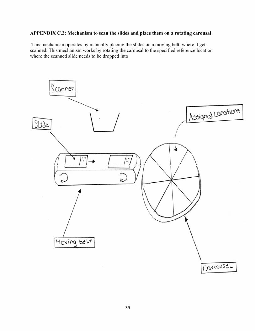
39��
APPENDIX C.2: Mechanism to scan the slides and place them on a rotating carousal
This mechanism operates by manually placing the slides on a moving belt, where it gets scanned. This mechanism works by rotating the carousal to the specified reference location where the scanned slide needs to be dropped into
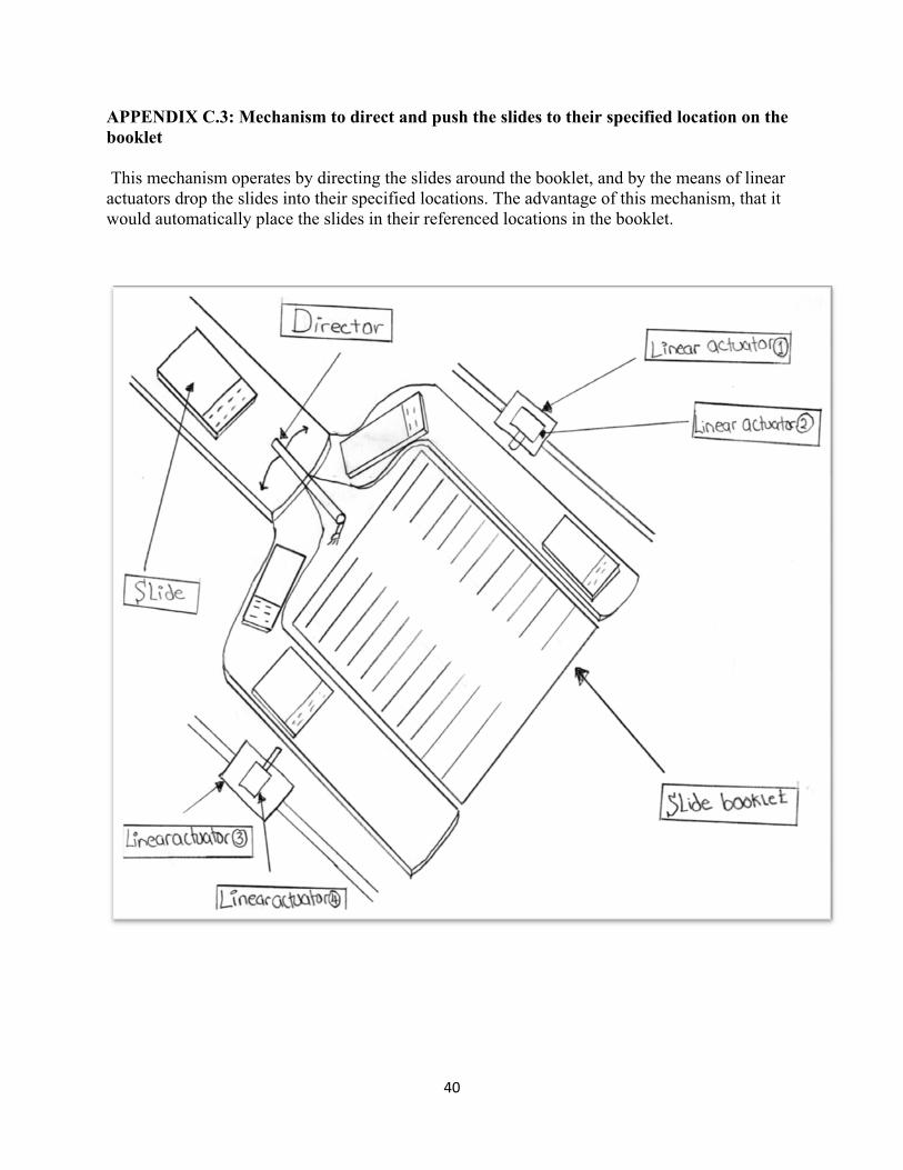
40��
APPENDIX C.3: Mechanism to direct and push the slides to their specified location on the booklet
This mechanism operates by directing the slides around the booklet, and by the means of linear actuators drop the slides into their specified locations. The advantage of this mechanism, that it would automatically place the slides in their referenced locations in the booklet.

41��
APPENDIX C.4: Mechanism to automatically retrieve the slides from the holder This mechanism operates by placing the holder of the slides on an inclined rack facing a rigid plate. The rigid plate will be mounted on top of an inclined moving belt with a small gap that allows one slide to fall at a time. The advantage of this mechanism is that it eliminates human interference in manually placing the slides on the moving belt.

42��
APPENDIX C.5: Mechanism for using a suction cup to pick up the slides
This mechanism would be implemented on our design to pick up the slides and place them on a specific location. The advantage of this mechanism is that it would eliminate the human interference in both picking up the slide and placing it in the booklet.

43��
APPENDIX C.6: Mechanism to automatically align the slide on the belt This mechanism can be implemented to automatically align the slides on the belt and eliminate the error of misalignment. The mechanism works by having two inclined belts moving at a faster rate than the horizontal belt to re-align the slide.

44��
APPENDIX C.7: Mechanism to sort the slides by directing them to distinct locations This mechanism sorts the slides by directing them to a specific location. The rotatable table with rollers will rotate in the specified orientation to guide the slide to its referenced direction. This mechanism could be implemented on our design to change the orientation of the slides if needed.

45��
APPENDIX D.1: Drawer View of Prototype Design Concept
APPENDIX D.2: Top View of Prototype Design Concept
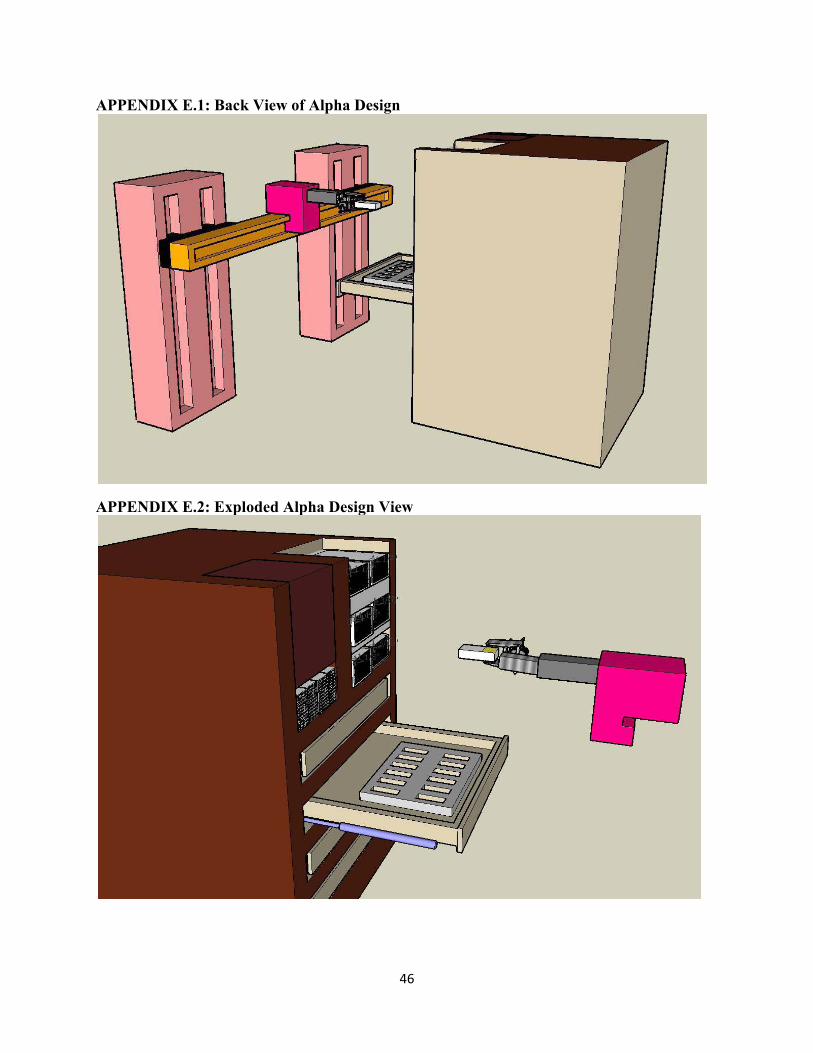
46��
APPENDIX E.1: Back View of Alpha Design
APPENDIX E.2: Exploded Alpha Design View

47��
APPENDIX F.1: Gripper appendage placing slide into the tray
APPENDIX F.2: Gripper appendage holding the slide

48��
APPENDIX F.3: Gripper Appendage CAD drawings (Dimensions in mm)
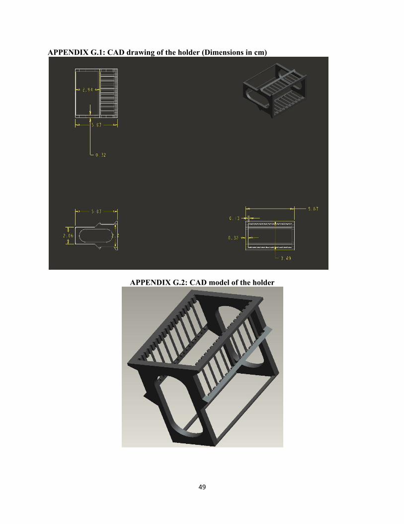
49��
APPENDIX G.1: CAD drawing of the holder (Dimensions in cm)
APPENDIX G.2: CAD model of the holder

50��
Appendix H: Tray CAD Drawing (Dimensions in mm)

51��
APPENDIX I.1: Rack CAD Drawing with detailed dimensions (Dimensions in mm)

52��
APPENDIX I.2: Rack static analysis with assumption of maximum load Static�analysis�of�the�rack�
�
Free�Body�Diagram�of�the�Holder�
�
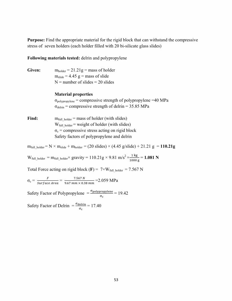
53��
Purpose: Find the appropriate material for the rigid block that can withstand the compressive stress of seven holders (each holder filled with 20 bi-silicate glass slides)
Following materials tested: delrin and polypropylene
Given: mholder = 21.21g = mass of holder mslide = 4.45 g = mass of slide N = number of slides = 20 slides Material properties �polypropylene = compressive strength of polypropylene =40 MPa �delrin = compressive strength of delrin = 35.85 MPa Find: mfull_holder = mass of holder (with slides) Wfull_holder = weight of holder (with slides) �c = compressive stress acting on rigid block Safety factors of polypropylene and delrin
mfull_holder = N × mslide + mholder = (20 slides) × (4.45 g/slide) + 21.21 g = 110.21g
Wfull_holder = mfull_holder× gravity = 110.21g × 9.81 m/s2 × ����
������ = 1.081 N
Total Force acting on rigid block (F) = 7×Wfull_holder = 7.567 N
�c = �
��� ����� = �������
����������������� =2.059 MPa
Safety Factor of Polypropylene = ����������� !
�" = 19.42
Safety Factor of Delrin = �# ��$!�"
= 17.40

54��
APPENDIX I.3: New rack design engineering drawing

55��
APPENDIX J.1.1: X-Axis thrust curve

56��
APPENDIX J.1.2: X-Axis linear actuator engineering drawing

57��
APPENDIX J.2.1:Y-Axis thrust curve
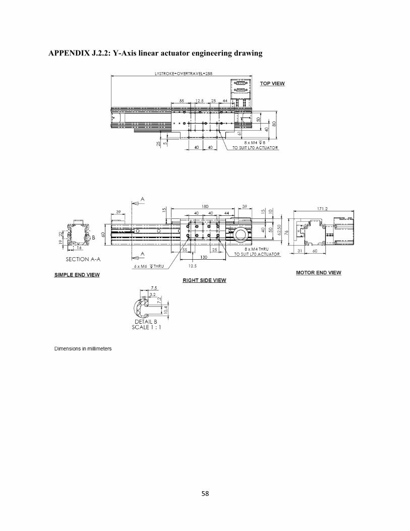
58��
APPENDIX J.2.2: Y-Axis linear actuator engineering drawing
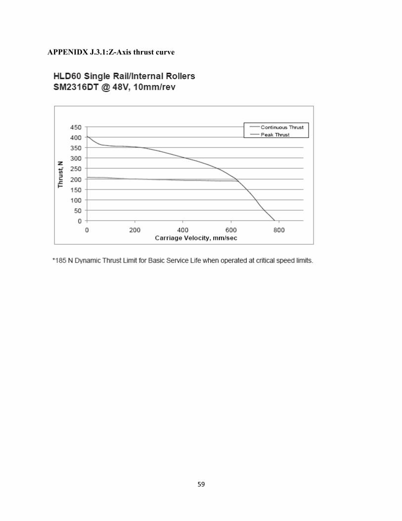
59��
APPENIDX J.3.1:Z-Axis thrust curve

60��
APPENDIX J.3.2: Z-Axis linear actuator engineering drawing

61��
APPENDIX K.1: Programming language Pugh chart
Evaluation�Criteria�Options�
C/C++� Python�Shell�
scripting�
Rapid�Prototyping� �� +� +�Learning�curve� �� +� +�Cross�platform� +� +� ��Embedded�controls� +� �� ��
Debugging� �� 0� 0�Ease�of�use� �� 0� +�
Speed� +� +� +�Support� +� +� ��
Total� 2� 4� 1�

62��
APPENDIX K.2: Programming layout
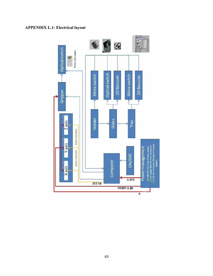
63��
APPENDIX L.1: Electrical layout

64��
APPENDIX M.1: Python Script for motor initialization # Author: Sudeep Pillai
import time import serial print 'Serial Port Initialization...' s= serial.Serial('/dev/ttyS0',9600, timeout=.1) print 's: ', s.portstr mAll=chr(128) m1=chr(129) m2=chr(130) m3=chr(131) s.write(mAll+'ECHO_OFF \r\n'); time.sleep(1) s.write(mAll+'SADDR1 \r\n'); time.sleep(1) s.write(m1+'ECHO \r\n'); time.sleep(1) s.write(m1+'SLEEP \r\n'); time.sleep(1) s.write(mAll+'SADDR2 \r\n'); time.sleep(1) s.write(m2+'ECHO \r\n'); time.sleep(1) s.write(m2+'SLEEP \r\n'); time.sleep(1) s.write(mAll+'SADDR3 \r\n'); time.sleep(1) s.write(m3+'ECHO \r\n'); time.sleep(1) s.write(m3+'SLEEP \r\n'); time.sleep(1) s.write(m1+'WAKE \r\n'); time.sleep(1) s.write(m2+'WAKE \r\n'); time.sleep(1) s.write(m3+'WAKE \r\n');

65��
time.sleep(1) s.write(m1+'ZS \r\n'); s.write(m2+'ZS \r\n'); s.write(m3+'ZS \r\n'); s.write(m1+'RBs \r\n') syntaxFlagm1=s.readline() s.write(m2+'RBs \r\n') syntaxFlagm2=s.readline() s.write(m3+'RBs \r\n') syntaxFlagm3=s.readline() print 'Homing motor 1' s.write(m1+'RUN \r\n');s.readline() time.sleep(4) print 'Homing motor 2' s.write(m2+'RUN \r\n');s.readline() time.sleep(4) print 'Homing motor 3' s.write(m3+'RUN \r\n');s.readline() time.sleep(4) print 'Motor addressing complete' print 'Syntax Flags: ', syntaxFlagm1, syntaxFlagm2, syntaxFlagm3
66��
APPENDIX M.2: Python Script sequence for slide placement �#Author: Sudeep Pillai import serial import string import time import os print 'Serial Port Initialization...' ser0 = serial.Serial('/dev/ttyS0',9600, timeout=.1) print 'ser0: ', ser0.portstr ser1 = serial.Serial('/dev/ttyS1',9600, timeout=.1) print 'ser1: ', ser1.portstr ser0.flushInput() ser1.flushInput() m0=chr(128) m1=chr(129) m2=chr(130) m3=chr(131) #bufloc=[((1,1),(1,2),(1,3)),((2,1),(2,2),(2,3))]############### trayloc = [((2300,-3800),(2300,-17500),(2300,-31500),(2300,-45200),(2300,-58500)),((-39300,-3800),(-39300,-17500),(-39300,-31500),(-39300,-45200),(-39300,-58500))] # same as bufloc (Zcol,Xrow) # C1 R1 X =--3800 Y -185000 Z = 1500 retract after releasing by 1500 (3000) #C2 R1 X =-3800 Z=-39300 holder1loc = [(-9800,-63300),(-9800,-64100),(-9800,-65600),(-9800,-66900),(-9800,-68300),(-9800,-69700),(-9800,-71000),(-9800,-72300),(-9800,-73900),(-9800,-75000)]##same as bufloc (Xcol, Yrow) print 'Calibrated ', len(holder1loc), ' slide positions in the holder....'

67��
raw_input() print 'Refill holder zone' holder1 = [] for i in range(1,21): holder1.append(1) #Positions ztrans = -25000 ############# ## Move in XY depth zpickholder = -70500 ############# ## Pick from holder depth zpickbuffer = 0 ############# ## Pick from buffer depth zplace = 0 ############# ## Place in buffer zone depth zretract = 1500 ############# ## Retract while placing in tray yplace = -185700 ############# ## Place in tray height yabovetray = -178000 ############# Vpick = 60000 ############# Vplace = 60000 ############# Vretract = 200000 ############# A = 2000 V = 200000 def refillHolder(): holder1 = [] for slideno in range(1,21): holder1.append(1) def readBar(): value=ser1.readline() return value def readSlideLoc(): value = [zone,var1,var2] return value def homeMotors(): mAll=chr(128) m1=chr(129) m2=chr(130) m3=chr(131) print 'Clearing flags' ser0.write(m1+'ZS \r\n') ser0.write(m2+'ZS \r\n')

68��
ser0.write(m3+'ZS \r\n') print 'Homing motor 1...' # raw_input() ser0.write(m1+'RUN \r\n') time.sleep(4) print 'Homing motor 2...' # raw_input() ser0.write(m2+'RUN \r\n') time.sleep(4) print 'Homing motor 3...' # raw_input() ser0.write(m3+'RUN \r\n') time.sleep(4) ser0.flushInput() def clearFlags(motor): ser0.write(motor+'ZS \r\n') ser0.flushInput() def RV(motor): ser0.write(motor+'RV \r\n') time.sleep(1) vel = ser0.readline() vel = vel.split() if len(vel) > 1: if vel[1]=='0': print 'Vel: ', vel[1] return 0 else: return 1 def Bt(motor): ser0.write(motor+'Bt \r\n') traj = ser0.readline() traj = traj.split() print traj def waitOnMotor(motor): while True: if RV(motor) == 0: break def writeToMotor(motor,A,V,P): sendstring = 'A='+ str(A) + ' V=' + str(V) + ' P=' + str(P) + ' G \r\n'

69��
print sendstring, '...' # raw_input() ser0.write(motor+sendstring) time.sleep(.5) ser0.flushInput() waitOnMotor(motor) def moveToBuffer(col,row): Xcol,Yrow = bufloc[col][row] print 'Move To Buffer....' # raw_input() writeToMotor(m3,A,V,ztrans) writeToMotor(m1,A,V,Xcol) writeToMotor(m2,A,V,Yrow) def moveToTray(col,row): Zcol,Xrow = trayloc[col][row] print 'Move To Tray........' # raw_input() writeToMotor(m1,A,10000,Xrow) writeToMotor(m2,A,200000,yabovetray) writeToMotor(m3,A,V,Zcol) # writeToMotor(m2,A,V,ztrans) def moveToHolder(row): #************** # raw_input('Move to holder zone...') print 'Move to slide', row, ' in holder' Xcol,Yrow = holder1loc[row-1] 'Moving to X = ', Xcol, ' Y = ', Yrow , '...' # raw_input() writeToMotor(m3,A,V,ztrans) writeToMotor(m1,A,V,Xcol) writeToMotor(m2,A,V,Yrow) def moveToGrip(zone): #FIX################# # if zone == 'holder': # raw_input('Move To Grip in holder...') releaseGrip() writeToMotor(m3,A,Vpick,zpickholder) gripSlide() time.sleep(1) writeToMotor(m3,A,Vpick,ztrans) # if zone == 'buffer':

70��
# print 'Move To Grip in Buffer' # releaseGrip() # writeToMotor(m3,A,Vpick,zpickbuffer) # gripSlide() # time.sleep(1) # writeToMotor(m3,A,Vpick,ztrans) def releaseGrip(): print 'Loose grip...' # raw_input() os.system("./pwm 55 &") time.sleep(1) ser0.flushInput() os.system("ps | grep pwm > pwmrun.txt") file = open("pwmrun.txt","r") tmp = file.read(10) tmp = tmp.split() print 'Killing ' , tmp[0] os.system('kill '+tmp[0]) def releaseGripAboveSlide(): print 'Loose grip...' # raw_input() os.system("./pwm 45 &") time.sleep(1) ser0.flushInput() os.system("ps | grep pwm > pwmrun.txt") file = open("pwmrun.txt","r") tmp = file.read(10) tmp = tmp.split() print 'Killing ' , tmp[0] os.system('kill '+tmp[0]) def gripSlide(): print 'Firm grip...' # raw_input() ser0.flushInput() os.system("./pwm 75 &") ser0.flushInput() def killGrip(): os.system("ps | grep pwm > pwmrun.txt") file = open("pwmrun.txt","r") tmp = file.read(10) tmp = tmp.split()
71��
print 'Killing ' , tmp[0] os.system('kill '+tmp[0]) def placeSlide(zone): print 'Placing slide in ', zone, '...' # raw_input() if zone == 'buffer': print 'Move To Place slide in buffer' writeToMotor(m3,A,Vplace,zpickbuffer) time.sleep(1) killGrip() releaseGrip() writeToMotor(m3,A,Vretract,ztrans) if zone == 'tray': print 'Move To Place slide in tray...' # raw_input() writeToMotor(m2,A,Vplace,yplace) time.sleep(1) releaseGripAboveSlide() writeToMotor(m2,A,Vplace,yplace+1700) writeToMotor(m3,A,Vretract,zretract) writeToMotor(m2,A,V,yabovetray) clearFlags(m1) clearFlags(m2) clearFlags(m3) ser0.flushInput() print 'Clearing flags...' raw_input('Start sequence....') gripSlide() killGrip() while 1: for slide in range(1,21): print 'Processing slide ', slide if holder1[slide-1]: moveToHolder(slide) moveToGrip('holder') zone,var1, var2 = readSlideLoc() if zone == 'tray': #var1 = col, var2 = row of tray moveToTray(var1,var2) placeSlide(zone)

72��
elif zone == 'buffer': #var1 = col, var2 = row of buffer moveToBuffer(var1,var2): else: print 'Debug ##'
�

73��
APPENDIX N.1: Holder with Glass Slides
�
APPENDIX N.2: Holder Rack with Glass Slides

74��
APPENDIX N.3: Slide with Bar Code
APPENDIX N.4: Buffer Zone with 2D Bar Code Slides

75��
APPENDIX N.5: Buffer Zone Glass Slide Clearance View
APPENDIX N.6: Alternate Slide Rack Design with Cover
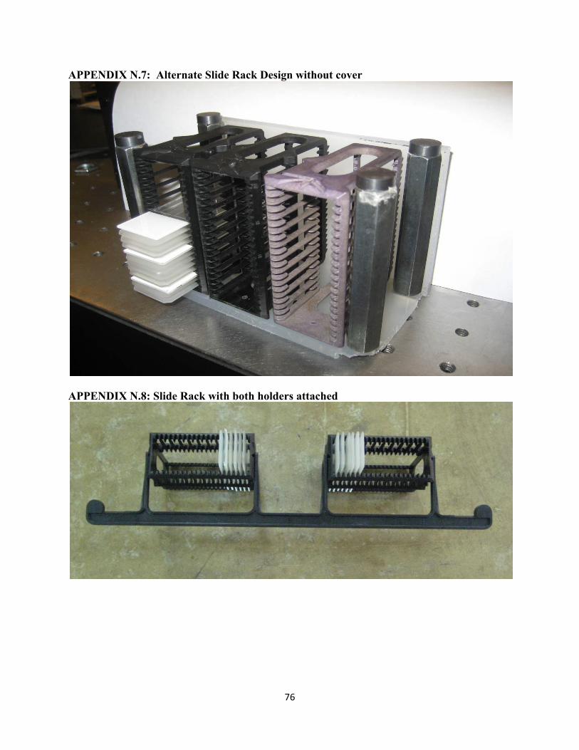
76��
APPENDIX N.7: Alternate Slide Rack Design without cover
APPENDIX N.8: Slide Rack with both holders attached
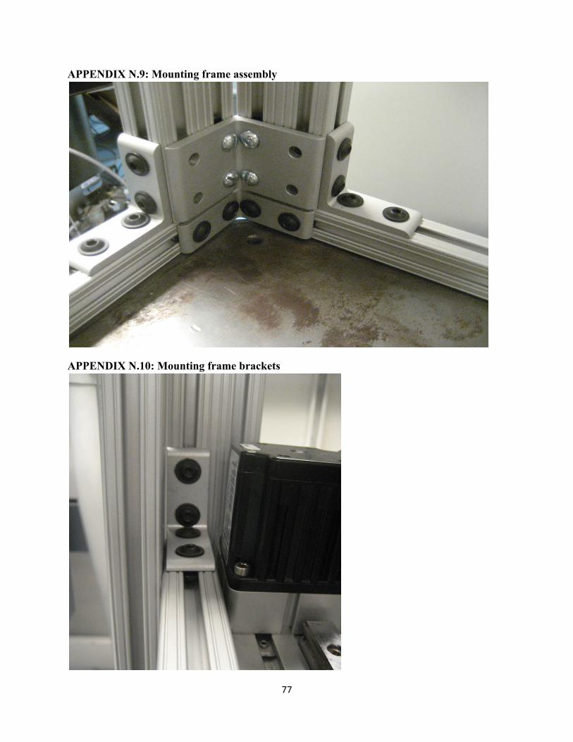
77��
APPENDIX N.9: Mounting frame assembly
APPENDIX N.10: Mounting frame brackets
�
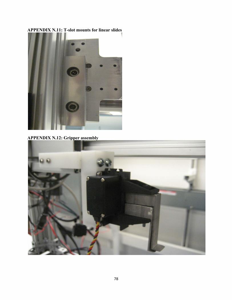
78��
APPENDIX N.11: T-slot mounts for linear slides
APPENDIX N.12: Gripper assembly
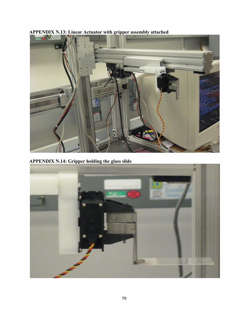
79��
APPENDIX N.13: Linear Actuator with gripper assembly attached
APPENDIX N.14: Gripper holding the glass slide

80��
APPENDIX N.15: Gripper Picking up slide from the holder
APPENDIX N.16: Another view of gripper picking up slide

81��
APPENDIX N.17: Gripper placing slide in tray
APPENDIX N.18: Top view of gripper placing slide in tray

82��
APPENDIX N.19: Python script commanding gripper to move to holder position
APPENDIX N.20: Running the python script
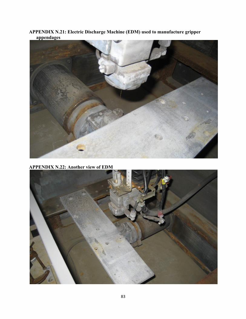
83��
APPENDIX N.21: Electric Discharge Machine (EDM) used to manufacture gripper appendages
APPENDIX N.22: Another view of EDM
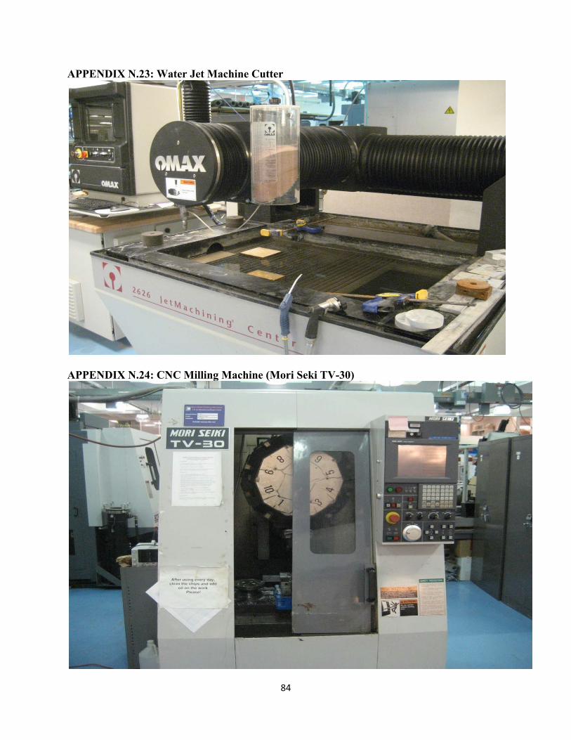
84��
APPENDIX N.23: Water Jet Machine Cutter
APPENDIX N.24: CNC Milling Machine (Mori Seki TV-30)
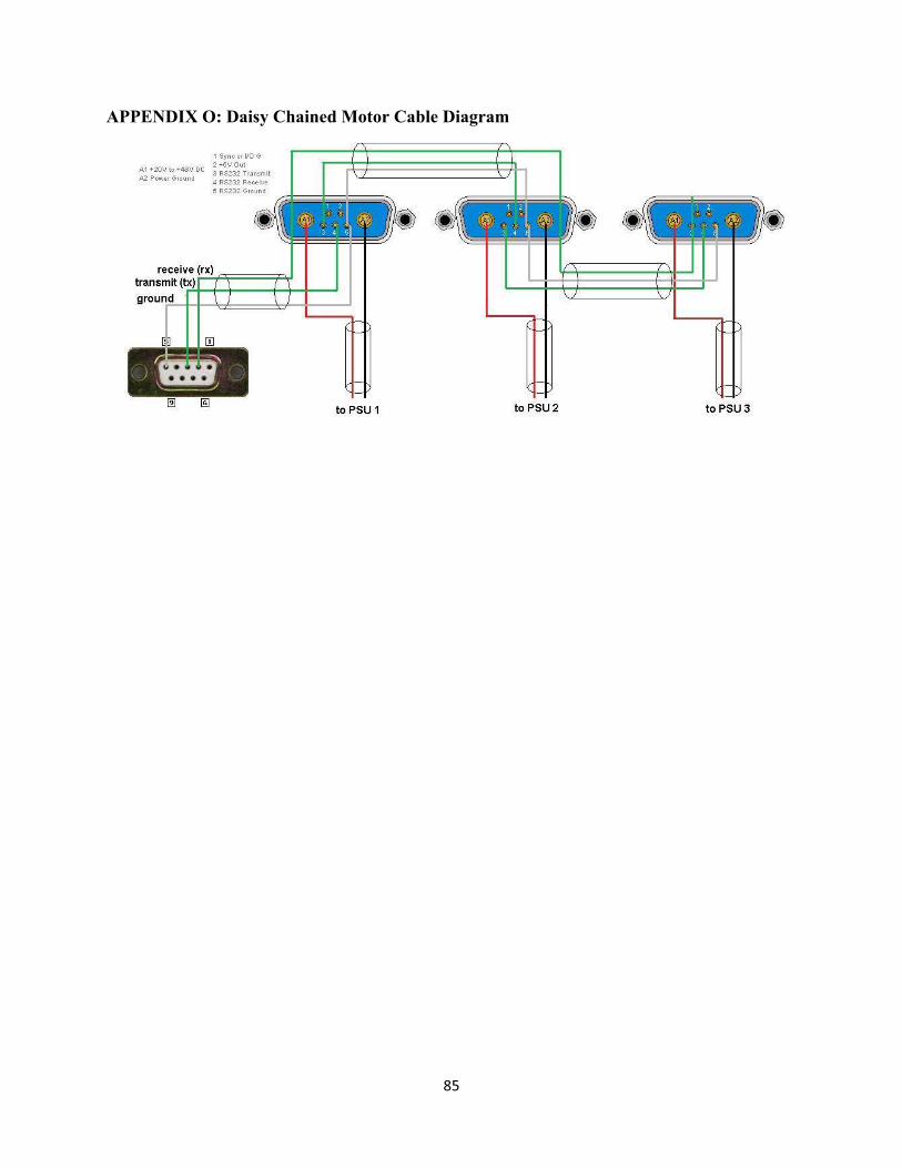
85��
APPENDIX O: Daisy Chained Motor Cable Diagram
�

86��
BIOGRAPHIES
Ramez Herrick I am originally from Cairo, Egypt. My family moved to the United States in 2002. I have enjoyed receiving a degree in mechanical engineering, but I want to start my career in business consulting. My recent work experience has been for Marathon Petroleum Corporation. I took two semesters off from school to work on a co-op in KY. I will graduate in May 2009. My ideal job in the consulting field would be with Accenture
Andrew Huang Andrew Huang is a senior in Mechanical Engineering with a Musicology minor from Ann Arbor, Michigan. He was born in Toronto, Ontario and lived there until the age of 8. He currently works part time as an Engineering Technician and SQL programmer at the US Environmental Protection Agency. He really enjoys new experiences and learning about different cultures and ethnicities. Andrew plays the guitar, trombone, euphonium, piano, and drums for fun during his spare time. His other hobbies include hiking, poker, blackjack, board games, football, and ultimate Frisbee. He is the current Publicity Chair for the American Society of Mechanical Engineers and has been an active member for the past three years. He hopes to find a full time job in the biomedical or space systems engineering fields but is open to other opportunities. He intends to pursue a MSE in an engineering related field and visit Europe in the future.
Sudeep Pillai Sudeep Pillai is senior in Mechanical Engineering hoping to pursue a career in intelligent vehicle systems. His past research involves working with autonomous vehicles, computer vision and is currently an active member/co-founder of the UM::Autonomy Team. In this team, he co-lead a team (2007-2008) of interdisciplinary students to build an autonomous vehicle capable of buoy navigation and path planning. He intends to pursue his interests with a MS in EE systems/CS after a few years of experience in the R&D industry. He also worked at Segway Inc. this summer (’08) developing concepts and prototypes whilst working with a talented product development team. His hobbies include reading tech-blogs and using productivity tools in his daily life because he thinks life is too short. He enjoys playing pretty much every sport, but especially loves squash primarily because he won several games against a team member of the Trinidad & Tobago National Squash Team.
Marshall Sunshine Marshall Sunshine is senior in Mechanical Engineering that is also pursuing a minor in Economics. He is originally from Atlanta, Georgia, and he hopes to return there upon graduation. Marshall’s hobbies tend to revolve around athletics and exercise. His research experience is in the field of Civil & Environmental Engineering, which he obtained the Georgia Institute of Technology. At Georgia Tech, he was studying the patterns of traffic flow monitoring through the use of a Geographic Information System. His recent work experience was at Revenue Analytics, a Price Optimization Consulting Firm, where he was an intern on the strategy team. Marshall is currently searching for jobs in business consulting, but he is debating the pursuit of a Masters Degree in Industrial Engineering.