computer controlled fluid friction in pipes unit with
TRANSCRIPT

AFTC
www.edibon.comProducts
Products rangeUnits
8.-Fluid Mechanics & Aerodynamics
1 Unit: AFTC. Fluid Friction in Pipes Unit with Hydraulics Bench (FME00)
Computer Controlled Fluid Friction in Pipes Unit with Hydraulics Bench (FME00),
with SCADA
Software for:4
- Data Acquisition- Data Management
- Computer ControlData
AcquisitionBoard
32 Control
Interface Box
TeachingTechnique
used
Computer(not included in the supply)
Cables and Accessories Manuals
5
6
* Minimum supply always includes: 1 + 2 + 3 + 4 + 5 + 6 (Computer not included in the supply)
Worlddidac Quality Charter Certificate
Worlddidac Member
European Union Certificate(total safety)
(Worlddidac Member)
ISO 9000: Quality Management(for Design, Manufacturing,
Commercialization and After-sales service)
Certificates ISO 14000 and ECO-Management and Audit Scheme
(environmental management) Page 1
OPEN CONTROL+
MULTICONTROL+
REAL TIME CONTROL
EDIBON SCADA System
Technical Teaching Equipment
Advanced Real-Time SCADA.
Open Control + Multicontrol + Real-Time Control.
Specialized EDIBON Control Software based on Labview.
National Instruments Data Acquisition board (250 KS/s , kilo samples per second).
Calibration exercises, which are included, teach the user how to calibrate a sensor and the importance of checking the accuracy of the sensors before taking measurements.
Projector and/or electronic whiteboard compatibility allows the unit to be explained and demonstrated to an entire class at one time.
Capable of doing applied research, real industrial simulation, training courses, etc.
Remote operation and control by the user and remote control for EDIBON technical support, are always included.
Totally safe, utilizing 4 safety systems (Mechanical, Electrical, Electronic & Software).
Designed and manufactured under several quality standards.
Optional CAL software helps the user perform calculations and comprehend the results.
This unit has been designed for future expansion and integration. A common expansion is the EDIBON Scada-Net (ESN) System which enables multiple students to simultaneously operate many units in a network.
Key features:

GENERAL DESCRIPTION
The knowledge of pressure losses occurring in pipes as well as in different hydraulic accessories is very important in the design and dimensioning of pipes systems. The Computer Controlled Fluid Friction in Pipes Unit with Hydraulics Bench (AFTC) is designed to determine the friction coefficient in pipes of several diameters and roughness, to study the pressure losses in different types of valves and different fittings and to compare different methods to measure the flow.
The unit contains five straight pipe sections made of different materials and with different diameters and roughness. Additionally, a wide range of accessories are included for the study of losses in straight pipes, several types of valves (gate, ball, angle seat, etc.), pipe fittings (in-line strainer, elbows, sudden widening, contraction, etc.).
The different pipe sections, valves and pipe fittings include several pressure measurement points with quick action connections to fit the tubing that is connected to the corresponding pressure measuring device.
With this unit friction pressure losses can be investigated over a wide range of Reynolds numbers, thereby covering the laminar, transitional and turbulent flow regimes. Two water manometric tubes and two displacement sensors allow to study the pressure losses in the laminar regimen. Two pressure sensors allow to obtain the pressure losses in the turbulent regimen. Additionally, it includes a flow sensor to measure and to compare measurements of flow with the Venturi tube and the Pitot tube.
The unit includes the Hydraulics Bench (FME00), which incorporates a sump tank and a centrifugal pump to make water flow in a close circuit and to supply it to the AFTC unit.
This Computer Controlled Unit is supplied with the EDIBON Computer Control System (SCADA), and includes: The unit itself + a Control Interface Box + a Data Acquisition Board + Computer Control and Data Acquisition Software Packages, for controlling the process and all parameters involved in the process.
PROCESS DIAGRAM AND UNIT ELEMENTS ALLOCATION
www.edibon.comPage 2
OPEN CONTROL+
MULTICONTROL+
REAL TIME CONTROL

AFTC. Unit
COMPLETE TECHNICAL SPECIFICATIONS (for main items)
1
With this unit there are several options and possibilities: - Main items: 1, 2, 3, 4, 5 and 6. - Optional items: 7, 8, 9, 10, 11 and 12.Let us describe first the main items (1 to 6): AFTC. Unit: This unit allows the detailed study of fluid friction pressure losses, which occur when a non-compressible fluid
flows through pipes, valves, pipe fittings and flow metering devices. Anodized aluminum structure with panel of painted steel. Main metallic elements made of stainless steel. Diagram in the front panel with similar distribution to the elements in the real unit. 5 Pipes of different diameter, material and roughness: Rough pipe (PVC): external diameter: 25mm. and internal diameter: 17 mm. Rough pipe (PVC): external diameter: 32 mm. and internal diameter: 23 mm. Smooth pipe (PMMA): external diameter: 10 mm. and internal diameter: 6.5 mm. Smooth pipe (PVC): external diameter: 20 mm. and internal
diameter: 16.5 mm. Smooth pipe (PVC): external diameter: 32 mm. and internal diameter: 26.5mm. Types of valves: Angle-seat valve: internal diameter: 20 mm. Gate valve: internal diameter: 20 mm. Diaphragm valve: internal diameter: 20 mm. Ball valve: internal diameter: 20 mm. Types of couplings: In-line strainer, internal diameter: 20 mm. Sudden widening. Its section changes from 25 mm to 40 mm. Sudden contraction. Its section changes from 40 mm to 25 mm. 90º elbow: inner diameter: 20 mm. “T” junction: inner diameter: 20 mm. 45º elbow: inner diameter: 20 mm. 45º “T” junction: inner diameter: 20 mm. Symmetrical “Y” branch: inner diameter of each pipe: 20 mm. Double 90º elbow: inner diameter: 20 mm. Special couplings (methacrylate): Pitot tube: length:30 mm., external diameter: 4mm and internal diameter: 2.5 mm. Venturi tube: length: 180 mm., larger section: 32mm. and smaller section: 20 mm. Diaphragm with measuring plate: larger diameter: 25mm. and smaller diameter: 20mm. The unit includes several ball valves to conduct the water flow through a certain pipe of the circuit and a
regulation valve to regulate the flow that runs through such pipe. 34 pressure tappings with quick action connections. Two pressure sensors, range: 0 – 30 psi. One flow sensor, range: 2 – 150 l./min. Two magnetic displacement sensors, range: 0-1 m. Two water manometers, length: 1000 mm. The unit is designed for use with the Hydraulics Bench (FME00): Mobile hydraulic bench, made of fibreglass reinforced polyester, and mounted on wheels for its mobility. Computer controlled centrifugal pump, 0.37 kW, 30 - 80 l./min., at 20.1 - 12.8 m. Sump tank, capacity: 165 l. Small channel, capacity: 8 l. Flow measurement: volumetric tank, gauged from 0 to 7 l. for low flow values and from 0 to 40 l. for high
flow values. Control valve to regulate the flow. The complete unit includes as well: Advanced Real-Time SCADA. Open Control + Multicontrol + Real-Time Control. Specialized EDIBON Control Software based on Labview. National Instruments Data Acquisition board (250 KS/s , kilo samples per second). Calibration exercises, which are included, teach the user how to calibrate a sensor and the
importance of checking the accuracy of the sensors before taking measurements. Projector and/or electronic whiteboard compatibility allows the unit to be explained and
demonstrated to an entire class at one time. Capable of doing applied research, real industrial simulation, training courses, etc. Remote operation and control by the user and remote control for EDIBON technical support, are
always included. Totally safe, utilizing 4 safety systems (Mechanical, Electrical, Electronic & Software). Designed and manufactured under several quality standards. Optional CAL software helps the user perform calculations and comprehend the results. This unit has been designed for future expansion and integration. A common expansion is the
EDIBON Scada-Net (ESN) System which enables multiple students to simultaneously operate many units in a network.
www.edibon.comPage 3
diameter: 6.5 mm.
DAB
5
6
*References 1 to 6 are the main items: AFTC + AFTC/CIB + DAB + AFTC/CCSOF + Cables and Accessories + Manuals are included in the minimum supply for enabling normal and full operation.
4
3
Complete Technical Specifications (for main items)
2
AFTC/CIB
AFTC/CCSOF
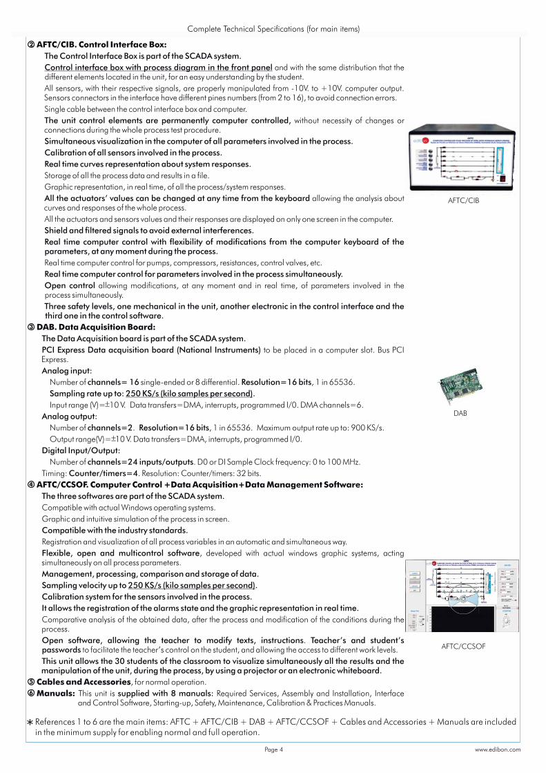
AFTC/CIB. Control Interface Box: The Control Interface Box is part of the SCADA system. Control interface box with process diagram in the front panel and with the same distribution that the
different elements located in the unit, for an easy understanding by the student. All sensors, with their respective signals, are properly manipulated from -10V. to +10V. computer output.
Sensors connectors in the interface have different pines numbers (from 2 to 16), to avoid connection errors. Single cable between the control interface box and computer. The unit control elements are permanently computer controlled, without necessity of changes or
connections during the whole process test procedure. Simultaneous visualization in the computer of all parameters involved in the process. Calibration of all sensors involved in the process. Real time curves representation about system responses. Storage of all the process data and results in a file. Graphic representation, in real time, of all the process/system responses. All the actuators’ values can be changed at any time from the keyboard allowing the analysis about
curves and responses of the whole process. All the actuators and sensors values and their responses are displayed on only one screen in the computer. Shield and filtered signals to avoid external interferences. Real time computer control with flexibility of modifications from the computer keyboard of the
parameters, at any moment during the process. Real time computer control for pumps, compressors, resistances, control valves, etc. Real time computer control for parameters involved in the process simultaneously. Open control allowing modifications, at any moment and in real time, of parameters involved in the
process simultaneously. Three safety levels, one mechanical in the unit, another electronic in the control interface and the
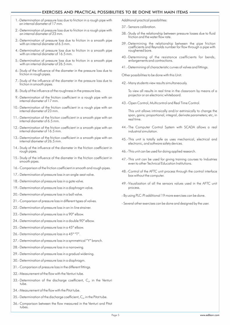
third one in the control software. DAB. Data Acquisition Board: The Data Acquisition board is part of the SCADA system. PCI Express Data acquisition board (National Instruments) to be placed in a computer slot. Bus PCI
Express. Analog input: Number of channels= 16 single-ended or 8 differential. Resolution=16 bits, 1 in 65536. Sampling rate up to: 250 KS/s (kilo samples per second). Input range (V)= 10 V. Data transfers=DMA, interrupts, programmed I/0. DMA channels=6. Analog output: Number of channels=2. Resolution=16 bits, 1 in 65536. Maximum output rate up to: 900 KS/s. Output range(V)= 10 V. Data transfers=DMA, interrupts, programmed I/0. Digital Input/Output: Number of channels=24 inputs/outputs. D0 or DI Sample Clock frequency: 0 to 100 MHz. Timing: Counter/timers=4. Resolution: Counter/timers: 32 bits. AFTC/CCSOF. Computer Control +Data Acquisition+Data Management Software: The three softwares are part of the SCADA system. Compatible with actual Windows operating systems. Graphic and intuitive simulation of the process in screen. Compatible with the industry standards. Registration and visualization of all process variables in an automatic and simultaneous way. Flexible, open and multicontrol software, developed with actual windows graphic systems, acting
simultaneously on all process parameters. Management, processing, comparison and storage of data. Sampling velocity up to .250 KS/s (kilo samples per second) Calibration system for the sensors involved in the process. It allows the registration of the alarms state and the graphic representation in real time. Comparative analysis of the obtained data, after the process and modification of the conditions during the
process. Open software, allowing the teacher to modify texts, instructions. Teacher’s and student’s
passwords to facilitate the teacher’s control on the student, and allowing the access to different work levels. This unit allows the 30 students of the classroom to visualize simultaneously all the results and the
manipulation of the unit, during the process, by using a projector or an electronic whiteboard. Cables and Accessories, for normal operation. Manuals: This unit is supplied with 8 manuals: Required Services, Assembly and Installation, Interface
and Control Software, Starting-up, Safety, Maintenance, Calibration & Practices Manuals.
www.edibon.comPage 4
1.-Determination of pressure loss due to friction in a rough pipe with an internal diameter of 17 mm.
2.- Determination of pressure loss due to friction in a rough pipe with an internal diameter of 23 mm.
3.- Determination of pressure loss due to friction in a smooth pipe with an internal diameter of 6.5 mm.
4.- Determination of pressure loss due to friction in a smooth pipe with an internal diameter of 16.5 mm.
5.- Determination of pressure loss due to friction in a smooth pipe with an internal diameter of 26.5 mm.
6.- Study of the influence of the diameter in the pressure loss due to friction in rough pipes.
7.- Study of the influence of the diameter in the pressure loss due to friction in smooth pipes.
8.- Study of the influence of the roughness in the pressure loss.
9.- Determination of the friction coefficient in a rough pipe with an internal diameter of 17 mm.
10.- Determination of the friction coefficient in a rough pipe with an internal diameter of 23 mm.
11.- Determination of the friction coefficient in a smooth pipe with an internal diameter of 6.5 mm.
12.- Determination of the friction coefficient in a smooth pipe with an internal diameter of 16.5 mm.
13.- Determination of the friction coefficient in a smooth pipe with an internal diameter of 26.5 mm.
14.- Study of the influence of the diameter in the friction coefficient in rough pipes.
15.- Study of the influence of the diameter in the friction coefficient in smooth pipes.
16.- Comparison of the friction coefficient in smooth and rough pipes.
17.- Determination of pressure loss in an angle-seat valve.
18.- Determination of pressure loss in a gate valve.
19.- Determination of pressure loss in a diaphragm valve.
20.- Determination of pressure loss in a ball valve.
21.- Comparison of pressure loss in different types of valves.
22.- Determination of pressure loss in an in-line strainer.
23.- Determination of pressure loss in a 90º elbow.
24.- Determination of pressure loss in a double 90º elbow.
25.- Determination of pressure loss in a 45º elbow.
26.- Determination of pressure loss in a 45º “T”.
27.- Determination of pressure loss in a symmetrical “Y” branch.
28.- Determination of pressure loss in a narrowing.
29.- Determination of pressure loss in a gradual widening.
30.- Determination of pressure loss in a diaphragm.
31.- Comparison of pressure loss in the different fittings.
32.- Measurement of the flow with the Venturi tube.
33.- Determination of the discharge coefficient, C , in the Venturi d
tube.
34.- Measurement of the flow with the Pitot tube.
35.- Determination of the discharge coefficient, C , in the Pitot tube.d
36.- Comparison between the flow measured in the Venturi and Pitot tubes.
Additional practical possibilities:
37.- Sensors calibration.
38.- Study of the relationship between pressure losses due to fluid friction and the water flow rate.
39.- Determining the relationship between the pipe friction coefficients and Reynolds number for flow through a pipe with roughened bore.
40.- Determining of the resistance coefficients for bends, enlargements and contractions.
41.- Determining of characteristic curves of valves and fittings.
Other possibilities to be done with this Unit:
42.- Many students view results simultaneously.
To view all results in real time in the classroom by means of a projector or an electronic whiteboard.
43.- Open Control, Multicontrol and Real Time Control.
This unit allows intrinsically and/or extrinsically to change the span, gains; proportional, integral, derivate parameters; etc, in real time.
44.- The Computer Control System with SCADA allows a real industrial simulation.
45.- This unit is totally safe as uses mechanical, electrical and electronic, and software safety devices.
46.- This unit can be used for doing applied research.
47.- This unit can be used for giving training courses to Industries even to other Technical Education Institutions.
48.- Control of the AFTC unit process through the control interface box without the computer.
49.- Visualization of all the sensors values used in the AFTC unit process.
- By using PLC-PI additional 19 more exercises can be done.
- Several other exercises can be done and designed by the user.
EXERCISES AND PRACTICAL POSSIBILITIES TO BE DONE WITH MAIN ITEMS
www.edibon.comwww.edibon.comPage 5
AFTC:
Unit: -Dimensions: approx. 2100 x 850 x 1000 mm.(82.67 x 33.46 x 39.37 inches approx.)
-Weight: 150 Kg. approx. (330.7 pounds approx.)
Hydraulics Bench (FME00):-Dimensions: 1130 x 730 x 1000 mm. approx. (44.48 x 28.74 x 39.37 inches approx.)
-Weight: 70 Kg. approx. (154.32 pounds approx.)
Control Interface Box: -Dimensions: 490 x 330 x 310 mm. approx. (19.29 x 12.99 x 12.20 inches approx.)
-Weight: 10 Kg. approx. (22 pounds approx.)
REQUIRED SERVICES DIMENSIONS & WEIGHTS-Electrical supply: single-phase 220-V/50Hz. or 110 V./60Hz.
-Water supply and drainage.
-Computer (PC).
AVAILABLE VERSIONSOffered in this catalogue:
- AFTC. Computer Controlled Fluid Friction in Pipes Unit with Hydraulics Bench (FME00).
Offered in other catalogue:
- AFT. Fluid Friction in Pipes Unit with Hydraulics Bench (FME00).- AFT/B. Fluid Friction in Pipes Unit with Basic Hydraulic Feed System (FME00/B).- AFT/P. Fluid Friction in Pipes Unit.
www.edibon.comPage 6
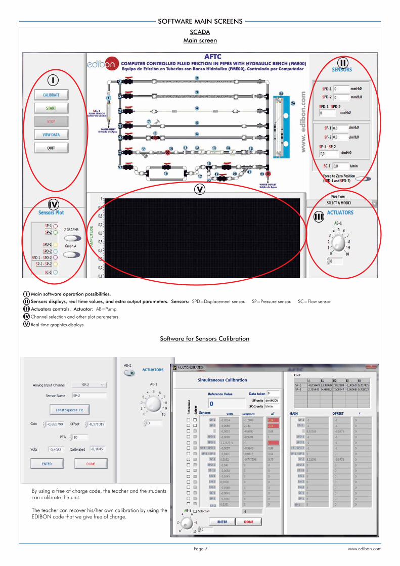
SOFTWARE MAIN SCREENS
SCADA
Software for Sensors Calibration
Main software operation possibilities.
Sensors displays, real time values, and extra output parameters. Sensors: SPD=Displacement sensor. SP=Pressure sensor. SC=Flow sensor.
Actuators controls. Actuator: AB=Pump.
Channel selection and other plot parameters.
Real time graphics displays.
III
II
I
IV
V
III
II
I
IV
V
Main screen
By using a free of charge code, the teacher and the studentscan calibrate the unit.
The teacher can recover his/her own calibration by using the EDIBON code that we give free of charge.
www.edibon.comPage 7

7
Additionally to the main items (1 to 6) described, we can offer, as optional, other items from 7 to 12.All these items try to give more possibilities for: a) Industrial configuration. (PLC) b) Technical and Vocational Education configuration. (CAI and FSS) c) Higher Education and/or Technical and Vocational Education configuration. (CAL) d) Multipost Expansions options. (Mini ESN and ESN)
PLC. Industrial Control using PLC (it includes PLC-PI Module plus PLC-SOF Control Software): -PLC-PI. PLC Module: Metallic box. Circuit diagram in the module front panel. Front panel: Digital inputs(X) and Digital outputs (Y) block: 16 Digital inputs, activated by switches and 16 LEDs for confirmation (red). 14 Digital outputs (through SCSI connector) with 14 LEDs for message (green). Analog inputs block: 16 Analog inputs (-10 V. to + 10 V.) (through SCSI connector). Analog outputs block: 4 Analog outputs (-10 V. to + 10 V.) (through SCSI connector). Touch screen: High visibility and multiple functions. Display of a highly visible status. Recipe function. Bar graph function. Flow display function. Alarm list. Multi language function. True type fonts. Back panel: Power supply connector. Fuse 2A. RS-232 connector to PC. USB 2.0 connector to PC. Inside: Power supply outputs: 24 Vdc, 12 Vdc, -12 Vdc, 12 Vdc variable. Panasonic PLC: High-speed scan of 0.32 sec. for a basic instruction. Program capacity of 32 Ksteps, with a sufficient comment area. Power supply input (100 to 240 V AC). DC input: 16 (24 V DC). Relay output: 14. High-speed counter. Multi-point PID control. Digital inputs/outputs and analog inputs/outputs Panasonic modules. Communication RS232 wire to computer (PC). Dimensions: 490 x 330 x 310 mm. approx. (19.29 x 12.99 x 12.20 inches approx.). Weight: 30 Kg. approx. (66 pounds approx.). -AFTC/PLC-SOF. PLC Control Software: For this particular unit, always included with PLC supply. The software has been designed using Labview and it follows the unit operation procedure and linked with the Control Interface Box used in the Computer
Controlled Fluid Friction in Pipes Unit with Hydraulics Bench (FME00) (AFTC).
a) Industrial configuration
COMPLETE TECHNICAL SPECIFICATIONS (for optional items)
Practices to be done with PLC-PI:
PLC CONTROL
PLC-SOF.Control Software
- Data Acquisition- Data Management
- Computer ControlData
AcquisitionBoard
PLC-PI. PLC Module
Software for: Control Interface Box
Unit
Page 8 www.edibon.com
1.- Control of the AFTC unit process through the control interface box without the computer.
2.- Visualization of all the sensors values used in the AFTC unit process.
3.- Calibration of all sensors included in the AFTC unit process.
4.- Hand on of all the actuators involved in the AFTC unit process.
5.- Realization of different experiments, in automatic way, without having in front the unit. (This experiment can be decided previously).
6.- Simulation of outside actions, in the cases hardware elements do not exist. (Example: test of complementary tanks, complementary industrial environment to the process to be studied, etc).
7.- PLC hardware general use and manipulation.
8.- PLC process application for AFTC unit.
9.- PLC structure.
10.- PLC inputs and outputs configuration.
11.- PLC configuration possibilities.
12.- PLC programming languages.
13.- PLC different programming standard languages.
14.- New configuration and development of new process.
15.- Hand on an established process.
16.- To visualize and see the results and to make comparisons with the AFTC unit process.
17.- Possibility of creating new process in relation with the AFTC unit.
18.- PLC Programming exercises.
19.- Own PLC applications in accordance with teacher and student requirements.
Unit
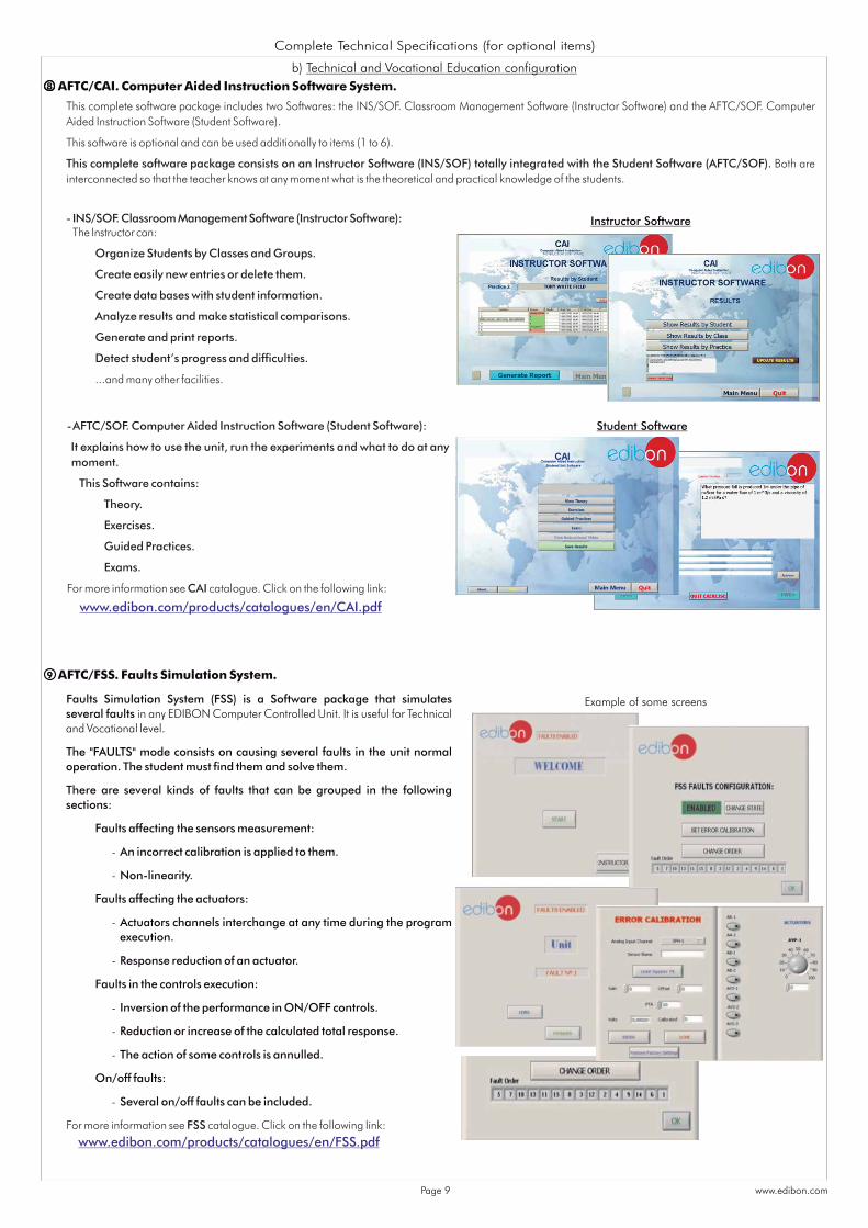
AFTC/CAI. Computer Aided Instruction Software System.8
b) Technical and Vocational Education configuration
Instructor Software
Student Software
9
This complete software package includes two Softwares: the INS/SOF. Classroom Management Software (Instructor Software) and the AFTC/SOF. Computer Aided Instruction Software (Student Software).
This software is optional and can be used additionally to items (1 to 6).
This complete software package consists on an Instructor Software (INS/SOF) totally integrated with the Student Software (AFTC/SOF). Both are interconnected so that the teacher knows at any moment what is the theoretical and practical knowledge of the students.
- INS/SOF. Classroom Management Software (Instructor Software): The Instructor can:
Organize Students by Classes and Groups.
Create easily new entries or delete them.
Create data bases with student information.
Analyze results and make statistical comparisons.
Generate and print reports.
Detect student’s progress and difficulties.
...and many other facilities.
- AFTC/SOF. Computer Aided Instruction Software (Student Software):
It explains how to use the unit, run the experiments and what to do at any moment.
This Software contains:
Theory.
Exercises.
Guided Practices.
Exams.
For more information see CAI catalogue. Click on the following link:
Example of some screens
AFTC/FSS. Faults Simulation System.
Faults Simulation System (FSS) is a Software package that simulates several faults in any EDIBON Computer Controlled Unit. It is useful for Technical and Vocational level.
The "FAULTS" mode consists on causing several faults in the unit normal operation. The student must find them and solve them.
There are several kinds of faults that can be grouped in the following sections:
Faults affecting the sensors measurement:
- An incorrect calibration is applied to them.
- Non-linearity.
Faults affecting the actuators:
- Actuators channels interchange at any time during the program execution.
- Response reduction of an actuator.
Faults in the controls execution:
- Inversion of the performance in ON/OFF controls.
- Reduction or increase of the calculated total response.
- The action of some controls is annulled.
On/off faults:
- Several on/off faults can be included.
For more information see FSS catalogue. Click on the following link:
Complete Technical Specifications (for optional items)
www.edibon.com/products/catalogues/en/CAI.pdf
www.edibon.com/products/catalogues/en/FSS.pdf
www.edibon.comPage 9

Mini Scada-NetSoftware
Computer ControlSoftware: ComputerControl+DataAcquisition+DataManagement
Mini ESN.EDIBON Mini Scada-Net System
30 StudentPosts
LOCAL NET
Instructor’sCentral
Computer
1 UNIT =up to 30 STUDENTS can
work simultaneously
OPEN CONTROL+
MULTICONTROL+
REAL TIME CONTROL+
MULTI STUDENT POST
ControlInterface
Box
Fluid Friction in Pipes Unit with Hydraulics Bench (AFTC)
Calculations
Plotting options
Information of constant values, unit conversionfactors and integral and derivative tables
d) Multipost Expansions options
Mini ESN. EDIBON Mini Scada-Net System allows up to 30 students to work with a Teaching Unit in any laboratory, simultaneously. It is useful for both, Higher Education and/or Technical and Vocational Education.
The Mini ESN system consists on the adaptation of any EDIBON computer controlled unit with SCADA integrated in a local network.
This system allows to view/control the unit remotely, from any computer integrated in the local net (in the classroom), through the main computer connected to the unit. Then, the number of possible users who can work with the same unit is higher than in an usual way of working (usually only one).
Main characteristics:
- It allows up to 30 students to work simultaneously with the EDIBON Computer Controlled Unit with SCADA, connected in a local net.
- Open Control + Multicontrol + Real Time Control + Multi Student Post.
- Instructor controls and explains to all students at the same time.
- Any user/student can work doing "real time" control/multicontrol and visualisation.
- Instructor can see in the computer what any user/student is doing in the unit.
- Continuous communication between the instructor and all the users/ students connected.
Main advantages:
- It allows an easier and quicker understanding.
- This system allows you can safe time and cost.
- Future expansions with more EDIBON Units.
AFTC/CAL. Computer Aided Learning Software (Results Calculation and Analysis).10
This Computer Aided Learning Software (CAL) is a Windows based
software, simple and very easy to use, specifically developed by EDIBON. It is
very useful for Higher Education level.
CAL is a class assistant that helps in doing the necessary calculations to
extract the right conclusions from data obtained during the experimental
practices.
CAL computes the value of all the variables involved and performs the
calculations.
It allows to plot and print the results. Within the plotting options, any
variable can be represented against any other.
Different plotting displays.
It has a wide range of information, such as constant values, unit conversion
factors and integral and derivative tables.
For more information see CAL catalogue. Click on the following link:
c) Higher Education and/or Technical and Vocational Education configuration
Complete Technical Specifications (for optional items)
For more information see Mini ESN catalogue. Click on the following link:
ESN. EDIBON Scada-Net System. This unit can be integrated, in the future, into a Complete Laboratory with many Units and many Students.
12
For more information see ESN catalogue. Click on the following link:
11 Mini ESN. EDIBON Mini Scada-Net System.
www.edibon.com/products/catalogues/en/CAL.pdf
www.edibon.com/products/catalogues/en/Mini-ESN.pdf
Note: The Mini ESNsystem can be usedwith any EDIBONcomputer controlledunit.
Page 10 www.edibon.com
www.edibon.com/products/catalogues/en/units/fluidmechanicsaerodynamics/esn-fluidmechanics/ESN-FLUID_MECHANICS.pdf

Minimum supply always includes:
Unit: AFTC. Fluid Friction in Pipes Unit with Hydraulics Bench (FME00).
AFTC/CIB. Control Interface Box.
DAB. Data Acquisition Board.
AFTC/CCSOF. Computer Control + Data Acquisition + Data Management Software.
Cables and Accessories, for normal operation.
Manuals.
* IMPORTANT: Under AFTC we always supply all the elements for immediate running as 1, 2, 3, 4, 5 and 6.
a) Industrial configuration
PLC. Industrial Control using PLC (it includes PLC-PI Module plus PLC-SOF Control Software):
- PCL-PI. PLC Module.
- AFTC/PLC-SOF. PLC Control Software.
b) Technical and Vocational configuration
AFTC/CAI. Computer Aided Instruction Software System.
AFTC/FSS. Faults Simulation System.
c) Higher Education and/or Technical and Vocational Education configuration
AFTC/CAL. Computer Aided Learning Software (Results Calculation and Analysis).
d) Multipost Expansions options
Mini ESN. EDIBON Mini Scada-Net System.
ESN. EDIBON Scada-Net System.
ORDER INFORMATION
1
6
2
3
4
5
Main items (always included in the supply) Optional items (supplied under order)specific
7
8
9
10
11
12
Page 11 www.edibon.com

AFTC. Unit: This unit allows the detailed study of fluid friction pressure losses, which occur when a non-compressible fluid flows through pipes, valves, pipe fittings and flow
metering devices. Anodized aluminum structure with panel of painted steel. Main metallic elements made of stainless steel. Diagram in the front panel with similar distribution to the elements in the real unit. 5 Pipes of different diameter, material and roughness: Rough pipe (PVC): external diameter: 25mm. and internal diameter: 17 mm. Rough pipe (PVC): external diameter: 32 mm. and internal diameter: 23 mm. Smooth pipe (PMMA): external diameter: 10 mm. and internal diameter: 6.5 mm. Smooth pipe (PVC): external diameter: 20 mm. and internal diameter: 16.5 mm. Smooth pipe (PVC): external diameter: 32 mm. and internal diameter: 26.5mm. Types of valves: Angle-seat valve: internal diameter: 20 mm. Gate valve: internal diameter: 20 mm. Diaphragm valve: internal diameter: 20 mm. Ball valve: internal diameter: 20 mm. Types of couplings: In-line strainer, internal diameter: 20 mm. Sudden widening. Its section changes from 25 mm to 40 mm. Sudden contraction. Its section changes from 40 mm to 25 mm. 90º elbow: inner diameter: 20 mm. “T” junction: inner diameter: 20 mm. 45º elbow: inner diameter: 20 mm. 45º “T” junction: inner diameter: 20 mm. Symmetrical “Y” branch: inner diameter of each pipe: 20 mm. Double 90º elbow: inner diameter: 20 mm. Special couplings (methacrylate): Pitot tube: length:30 mm., external diameter: 4mm and internal diameter: 2.5 mm. Venturi tube: length: 180 mm., larger section: 32mm. and smaller section: 20 mm. Diaphragm with measuring plate: larger diameter: 25mm. and smaller diameter: 20mm. The unit includes several ball valves to conduct the water flow through a certain pipe of the circuit and a regulation valve to regulate the flow that runs through
such pipe. 34 pressure tappings with quick action connections. Two pressure sensors, range: 0 – 30 psi. One flow sensor, range: 2 – 150 l./min. Two magnetic displacement sensors, range: 0-1 m. Two water manometers, length: 1000 mm. The unit is designed for use with the Hydraulics Bench (FME00): Mobile hydraulic bench, made of fibreglass reinforced polyester, and mounted on wheels for its mobility. Computer controlled centrifugal pump, 0.37 kW, 30 - 80 l./min., at 20.1 - 12.8 m. Sump tank, capacity: 165 l. Small channel, capacity: 8 l. Flow measurement: volumetric tank, gauged from 0 to 7 l. for low flow values and from 0 to 40 l. for high flow values. Control valve to regulate the flow. The complete unit includes as well: Advanced Real-Time SCADA. Open Control + Multicontrol + Real-Time Control. Specialized EDIBON Control Software based on Labview. National Instruments Data Acquisition board (250 KS/s , kilo samples per second). Calibration exercises, which are included, teach the user how to calibrate a sensor and the importance of checking the accuracy of the sensors before taking
measurements. Projector and/or electronic whiteboard compatibility allows the unit to be explained and demonstrated to an entire class at one time. Capable of doing applied research, real industrial simulation, training courses, etc. Remote operation and control by the user and remote control for EDIBON technical support, are always included. Totally safe, utilizing 4 safety systems (Mechanical, Electrical, Electronic & Software). Designed and manufactured under several quality standards. Optional CAL software helps the user perform calculations and comprehend the results. This unit has been designed for future expansion and integration. A common expansion is the EDIBON Scada-Net (ESN) System which enables multiple
students to simultaneously operate many units in a network. AFTC/CIB. Control Interface Box: The Control Interface Box is part of the SCADA system. Control interface box with process diagram in the front panel. The unit control elements are permanently computer controlled. Simultaneous visualization in the computer of all parameters involved in the process. Calibration of all sensors involved in the process. Real time curves representation about system responses. All the actuators’ values can be changed at any time from the keyboard allowing the analysis about curves and responses of the whole process. Shield and filtered signals to avoid external interferences. Real time computer control with flexibility of modifications from the computer keyboard of the parameters, at any moment during the process. Real time computer control for parameters involved in the process simultaneously. Open control allowing modifications, at any moment and in real time, of parameters involved in the process simultaneously. Three safety levels, one mechanical in the unit, another electronic in the control interface and the third one in the control software. DAB. Data Acquisition Board: The Data Acquisition board is part of the SCADA system. PCI Express Data acquisition board (National Instruments) to be placed in a computer slot. Analog input: Channels= 16 single-ended or 8 differential. Resolution=16 bits, 1 in 65536. Sampling rate up to: 250 KS/s (kilo samples per second). Analog output: Channels=2. Resolution=16 bits, 1 in 65536. Digital Input/Output: Channels=24 inputs/outputs. AFTC/CCSOF. Computer Control +Data Acquisition+Data Management Software: The three softwares are part of the SCADA system. Compatible with the industry standards. Flexible, open and multicontrol software, developed with actual windows graphic systems, acting simultaneously on all process parameters. Management, processing, comparison and storage of data. Sampling velocity up to 250 KS/s (kilo samples per second). Calibration system for the sensors involved in the process. It allows the registration of the alarms state and the graphic representation in real time. Open software, allowing the teacher to modify texts, instructions. Teacher’s and student’s passwords to facilitate the teacher’s control on the student, and
allowing the access to different work levels. This unit allows the 30 students of the classroom to visualize simultaneously all the results and the manipulation of the unit, during the process, by using a
projector or an electronic whiteboard. Cables and Accessories, for normal operation. Manuals: This unit is supplied with 8 manuals: Required Services, Assembly and Installation, Interface and Control Software, Starting-up, Safety, Maintenance,
Calibration & Practices Manuals.
TENDER SPECIFICATIONS (for main items)
1
2
56
4
3
Page 12 www.edibon.com
1.-Determination of pressure loss due to friction in a rough pipe with an internal diameter of 17 mm.
2.- Determination of pressure loss due to friction in a rough pipe with an internal diameter of 23 mm.
3.- Determination of pressure loss due to friction in a smooth pipe with an internal diameter of 6.5 mm.
4.- Determination of pressure loss due to friction in a smooth pipe with an internal diameter of 16.5 mm.
5.- Determination of pressure loss due to friction in a smooth pipe with an internal diameter of 26.5 mm.
6.- Study of the influence of the diameter in the pressure loss due to friction in rough pipes.
7.- Study of the influence of the diameter in the pressure loss due to friction in smooth pipes.
8.- Study of the influence of the roughness in the pressure loss.
9.- Determination of the friction coefficient in a rough pipe with an internal diameter of 17 mm.
10.- Determination of the friction coefficient in a rough pipe with an internal diameter of 23 mm.
11.- Determination of the friction coefficient in a smooth pipe with an internal diameter of 6.5 mm.
12.- Determination of the friction coefficient in a smooth pipe with an internal diameter of 16.5 mm.
13.- Determination of the friction coefficient in a smooth pipe with an internal diameter of 26.5 mm.
14.- Study of the influence of the diameter in the friction coefficient in rough pipes.
15.- Study of the influence of the diameter in the friction coefficient in smooth pipes.
16.- Comparison of the friction coefficient in smooth and rough pipes.
17.- Determination of pressure loss in an angle-seat valve.
18.- Determination of pressure loss in a gate valve.
19.- Determination of pressure loss in a diaphragm valve.
20.- Determination of pressure loss in a ball valve.
21.- Comparison of pressure loss in different types of valves.
22.- Determination of pressure loss in an in-line strainer.
23.- Determination of pressure loss in a 90º elbow.
24.- Determination of pressure loss in a double 90º elbow.
25.- Determination of pressure loss in a 45º elbow.
26.- Determination of pressure loss in a 45º “T”.
27.- Determination of pressure loss in a symmetrical “Y” branch.
28.- Determination of pressure loss in a narrowing.
29.- Determination of pressure loss in a gradual widening.
30.- Determination of pressure loss in a diaphragm.
31.- Comparison of pressure loss in the different fittings.
32.- Measurement of the flow with the Venturi tube.
33.- Determination of the discharge coefficient, C , in the Venturi tube.d
34.- Measurement of the flow with the Pitot tube.
35.- Determination of the discharge coefficient, C , in the Pitot tube.d
36.- Comparison between the flow measured in the Venturi and Pitot tubes.
Additional practical possibilities:
37.- Sensors calibration.
38.- Study of the relationship between pressure losses due to fluid friction and the water flow rate.
39.- Determining the relationship between the pipe friction coefficients and Reynolds number for flow through a pipe with roughened bore.
40.- Determining of the resistance coefficients for bends, enlargements and contractions.
41.- Determining of characteristic curves of valves and fittings.
Other possibilities to be done with this Unit:
42.- Many students view results simultaneously.
To view all results in real time in the classroom by means of a projector or an electronic whiteboard.
43.- Open Control, Multicontrol and Real Time Control.
This unit allows intrinsically and/or extrinsically to change the span, gains; proportional, integral, derivate parameters; etc, in real time.
44.- The Computer Control System with SCADA allows a real industrial simulation.
45.- This unit is totally safe as uses mechanical, electrical and electronic, and software safety devices.
46.- This unit can be used for doing applied research.
47.- This unit can be used for giving training courses to Industries even to other Technical Education Institutions.
48.- Control of the AFTC unit process through the control interface box without the computer.
49.- Visualization of all the sensors values used in the AFTC unit process.
- By using PLC-PI additional 19 more exercises can be done.
- Several other exercises can be done and designed by the user.
Exercises and Practical Possibilities to be done with Main Items
Tender Specifications (for main items)
Page 13 www.edibon.com

7
8
99
TENDER SPECIFICATIONS (for optional items)
a) Industrial configuration
b) Technical and Vocational Education configuration
Page 14 www.edibon.com
PLC. Industrial Control using PLC (it includes PLC-PI Module plus PLC-SOF Control Software): -PLC-PI. PLC Module: Metallic box. Circuit diagram in the module front panel. Digital inputs(X) and Digital outputs (Y) block: 16 Digital inputs. 14 Digital outputs. Analog inputs block: 16 Analog inputs. Analog outputs block: 4 Analog outputs. Touch screen. Panasonic PLC: High-speed scan of 0.32 sec. Program capacity of 32 Ksteps. High-speed counter. Multi-point PID control. Digital inputs/outputs and analog inputs/outputs Panasonic modules. -AFTC/PLC-SOF. PLC Control Software: For this particular unit, always included with PLC supply.
Practices to be done with PLC-PI: 1.- Control of the AFTC unit process through the control interface box without the computer. 2.- Visualization of all the sensors values used in the AFTC unit process. 3.- Calibration of all sensors included in the AFTC unit process. 4.- Hand on of all the actuators involved in the AFTC unit process. 5.- Realization of different experiments, in automatic way, without having in front the unit. (This experiment can be decided previously). 6.- Simulation of outside actions, in the cases hardware elements do not exist. (Example: test of complementary tanks, complementary industrial environment
to the process to be studied, etc). 7.- PLC hardware general use and manipulation. 8.- PLC process application for AFTC unit. 9.- PLC structure. 10.- PLC inputs and outputs configuration. 11.- PLC configuration possibilities. 12.- PLC programming languages. 13.- PLC different programming standard languages. 14.- New configuration and development of new process. 15.- Hand on an established process. 16.- To visualize and see the results and to make comparisons with the AFTC unit process. 17.- Possibility of creating new process in relation with the AFTC unit. 18.- PLC Programming exercises. 19.- Own PLC applications in accordance with teacher and student requirements.
AFTC/CAI. Computer Aided Instruction Software System. This complete software package consists on an Instructor Software (INS/SOF) totally integrated with the Student Software (AFTC/SOF). - INS/SOF. Classroom Management Software (Instructor Software): The Instructor can: Organize Students by Classes and Groups. Create easily new entries or delete them. Create data bases with student information. Analyze results and make statistical comparisons. Generate and print reports. Detect student’s progress and difficulties. -AFTC/SOF. Computer Aided Instruction Software (Student Software): It explains how to use the unit, run the experiments and what to do at any moment. This Software contains: Theory. Exercises. Guided Practices. Exams. AFTC/FSS. Faults Simulation System. Faults Simulation System (FSS) is a Software package that simulates several faults in any EDIBON Computer Controlled Unit. The "FAULTS" mode consists on causing several faults in the unit normal operation. The student must find them and solve them. There are several kinds of faults that can be grouped in the following sections: Faults affecting the sensors measurement: - An incorrect calibration is applied to them. - Non-linearity. Faults affecting the actuators: - Actuators channels interchange at any time during the program execution. - Response reduction of an actuator. Faults in the controls execution: - Inversion of the performance in ON/OFF controls. - Reduction or increase of the calculated total response. - The action of some controls is annulled. On/off faults: - Several on/off faults can be included.
*Specifications subject to change without previous notice, due to the convenience of improvements of the product.
Issue: ED01/13Date: November/2013
REPRESENTATIVE:
11
c) Higher Education and/or Technical and Vocational Education configuration
AFTC/CAL. Computer Aided Learning Software (Results Calculation and Analysis). This Computer Aided Learning Software (CAL) is a Windows based software, simple and very easy to use. CAL is a class assistant that helps in doing the necessary calculations to extract the right conclusions from data obtained during the experimental practices. CAL computes the value of all the variables involved and performs the calculations. It allows to plot and print the results. Within the plotting options, any variable can be represented against any other. Different plotting displays. It has a wide range of information, such as constant values, unit conversion factors and integral and derivative tables.
Mini ESN. EDIBON Mini Scada-Net System. EDIBON Mini Scada-Net System allows up to 30 students to work with a Teaching Unit in any laboratory, simultaneously. The Mini ESN system consists on the adaptation of any EDIBON computer controlled unit with SCADA integrated in a local network. This system allows to view/control the unit remotely, from any computer integrated in the local net (in the classroom), through the main computer connected to the
unit. Main characteristics: - It allows up to 30 students to work simultaneously with the EDIBON Computer Controlled Unit with SCADA, connected in a local net. - Open Control + Multicontrol + Real Time Control + Multi Student Post. - Instructor controls and explains to all students at the same time. - Any user/student can work doing "real time" control/multicontrol and visualisation. - Instructor can see in the computer what any user/student is doing in the unit. - Continuous communication between the instructor and all the users/students connected. Main advantages: - It allows an easier a quicker understanding. - This system allows you can safe time and cost. - Future expansions with more EDIBON Units. The system basically will consist of: This system is used with a Computer Controlled Unit. - Instructor’s computer. - Students’ computers. - Local Network. -Unit-Control Interface adaptation. -Unit Software adaptation. -Webcam. -Mini ESN Software to control the whole system. -Cables and accessories required for a normal operation.
d) Multipost Expansions options
10
Tender Specifications (for optional items)
C/ Del Agua, 14. Polígono Industrial San José de Valderas. 28918 LEGANÉS. (Madrid). SPAIN.Phone: 34-91-6199363 FAX: 34-91-6198647E-mail: [email protected] WEB site: www.edibon.com
Page 15