computer antenna modeling simplified – ke5kjd
TRANSCRIPT

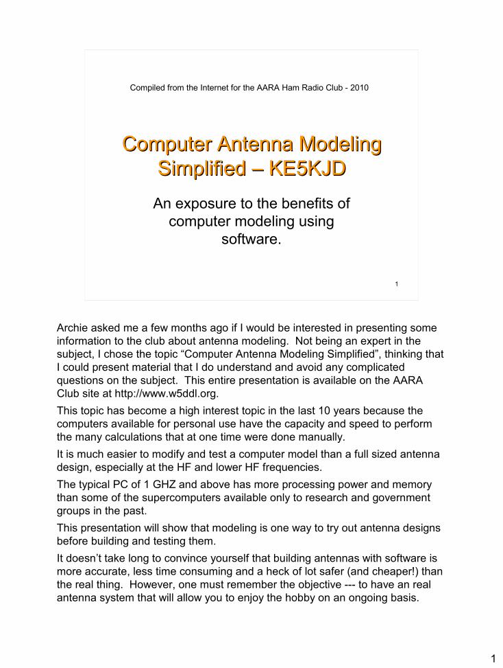
Computer Antenna Modeling Computer Antenna Modeling Simplified – KE5KJDSimplified – KE5KJD
An exposure to the benefits of computer modeling using
software.
Compiled from the Internet for the AARA Ham Radio Club - 2010

Antenna Modeling What is it?Antenna Modeling What is it?
Computerized antenna modeling is evaluating the performance of a system that is governed by the laws of physics.
Antenna-modeling programs are computer programs that use mathematics to calculate and predict the electrical performance of an antenna. Modeling usually has its limitations, partly because the mathematical model that we have to describe it can almost never be described in the same detail as the real thing (and especially its environment), and partly because of numerical limitations in the calculating code used or imposed by the developer.
The final limitation is the operator, who enters the data and who interprets the results. In all cases a good deal of knowledge and experience in the field of antennas is required in order to draw the correct conclusions and take the right decisions during the process of modeling. However almost anyone with a computer and data entry skills can select an antenna design of a given type and change it to match their constraints and view the results.

Start With Simple Equations Start With Simple Equations
Why Model AntennasWhy Model Antennas
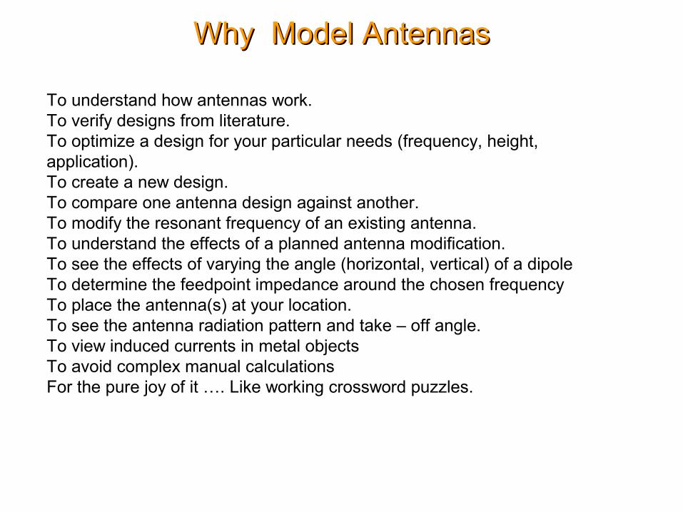
To understand how antennas work. To verify designs from literature. To optimize a design for your particular needs (frequency, height, application). To create a new design. To compare one antenna design against another.To modify the resonant frequency of an existing antenna.To understand the effects of a planned antenna modification.To see the effects of varying the angle (horizontal, vertical) of a dipoleTo determine the feedpoint impedance around the chosen frequencyTo place the antenna(s) at your location.To see the antenna radiation pattern and take – off angle.To view induced currents in metal objectsTo avoid complex manual calculationsFor the pure joy of it …. Like working crossword puzzles.
Questions Answered By ModelingQuestions Answered By Modeling
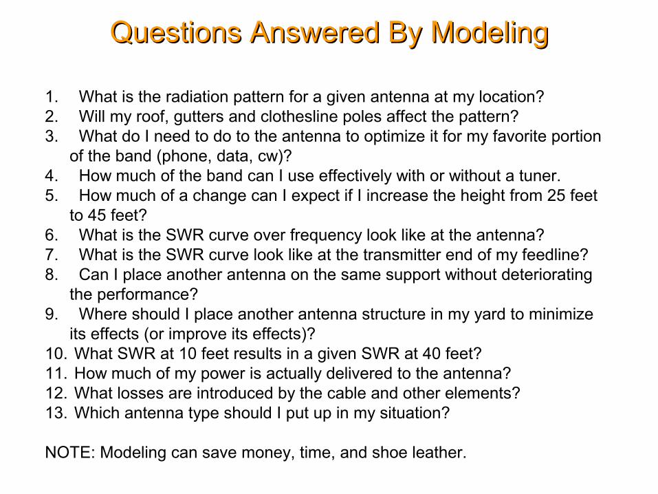
1. What is the radiation pattern for a given antenna at my location?2. Will my roof, gutters and clothesline poles affect the pattern?3. What do I need to do to the antenna to optimize it for my favorite portion
of the band (phone, data, cw)?4. How much of the band can I use effectively with or without a tuner.5. How much of a change can I expect if I increase the height from 25 feet
to 45 feet?6. What is the SWR curve over frequency look like at the antenna?7. What is the SWR curve look like at the transmitter end of my feedline?8. Can I place another antenna on the same support without deteriorating
the performance?9. Where should I place another antenna structure in my yard to minimize
its effects (or improve its effects)?10. What SWR at 10 feet results in a given SWR at 40 feet?11. How much of my power is actually delivered to the antenna?12. What losses are introduced by the cable and other elements?13. Which antenna type should I put up in my situation?
NOTE: Modeling can save money, time, and shoe leather.
How Software Modeling WorksHow Software Modeling Works
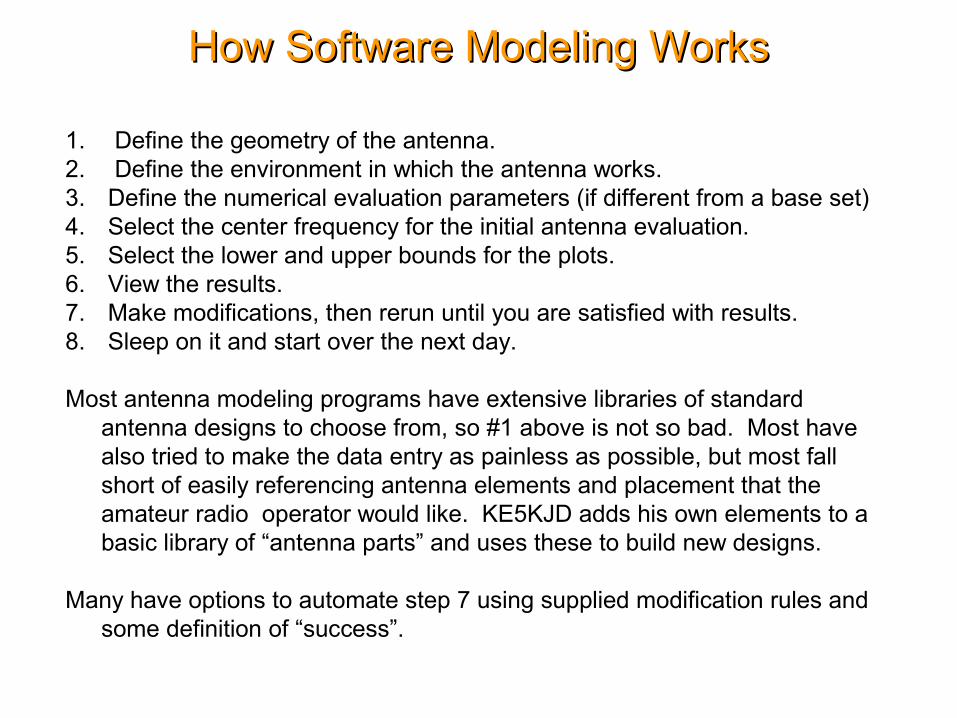
1. Define the geometry of the antenna.2. Define the environment in which the antenna works.3. Define the numerical evaluation parameters (if different from a base set)4. Select the center frequency for the initial antenna evaluation.5. Select the lower and upper bounds for the plots.6. View the results.7. Make modifications, then rerun until you are satisfied with results.8. Sleep on it and start over the next day.
Most antenna modeling programs have extensive libraries of standard antenna designs to choose from, so #1 above is not so bad. Most have also tried to make the data entry as painless as possible, but most fall short of easily referencing antenna elements and placement that the amateur radio operator would like. KE5KJD adds his own elements to a basic library of “antenna parts” and uses these to build new designs.
Many have options to automate step 7 using supplied modification rules and some definition of “success”.
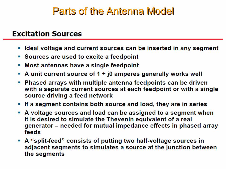
Parts of the Antenna ModelParts of the Antenna Model
Parts of the Antenna ModelParts of the Antenna Model

Parts of the Antenna ModelParts of the Antenna Model

Which Program Do I Use?Which Program Do I Use?
1. NEC – Numeric Electromagnetics Code2. NEC 2 – Public Domain - Single diameter wires3. 4NEC2 – Free version of NEC 24. EZNEC, EZNEC Pro W7EL – Active ham developer/Sales5. NEC – 4 Latest version from Lawrence Livemore Labs ($250 License)6. MMANA GAL – EZNEC with spreadsheet antenna definition.7. GAL ANA – MININEC 3 and NEC2 calculations. Demo version only, in
active development..
The MININEC versions are adequate for most applications. NEC 4 models most situations, including an accurate ground system. MMANA GAL does not have accurate results near ground but does include variable element diameters and tapered elements. NEC 4 has the most up to date features and is used by antenna design professionals.
You should look up these programs on the internet if you need additional information. KE5KJD uses MMANA GAL because it is free and does a reasonable job of calculating radiation patterns.
MMANA Antenna Modeling ProgramMMANA Antenna Modeling Program
Author: Makoto (Mako) Mori JE3HHT © 1999-2000Gontcharenko Gary DL2KQ-EU1TT developed and released English versions of MMANA in 2001-2002. Nobuyuki Oba JA7UDE wrote an English user manual in 2001. Software beta testing was provided by a group of fellow amateurs.
Cost: Freeware
MMANA is an antenna analyzing tool based on the moment method introduced in MININEC (Mini Numerical Electromagnetics Code) Version 3. MININEC should not be confused with NEC, which is a large antenna analysis program written in FORTRAN and designed to run on main-frame computers. A graphical user interface also was added that makes MMANA much easier to use than MININEC version it was ported from. (Some portions of later versions of MININEC are written in FORTRAN.)

MMANA/GAL Program FeaturesMMANA/GAL Program Features
• Both table-based and graphical-based editors for antenna design and definition
• A 3-dimensional graphical antenna viewer that shows antenna elements, element current distributions, and the elemental segmentations used.
• A far field radiation viewer that shows both horizontal and vertical far field radiation patterns (MMANA GAL 1.20 has 3-D far field display)
• A comparator that can be used to compare two or more computation results • An antenna element editor • An antenna wire editor • Tools for defining combinations of pipe or tube elements with stepped
diameters • A user-customizable automatic antenna optimizer capable of optimizing
antenna designs with respect to jX, SWR, Gain, F/B, Elevation, and Current • An antenna optimizer results display table with manual tuning capabilities • Antenna frequency characteristics plotting • An antenna specification file generator • Plus many other things, such as 3-dimensional antenna rotation, antenna
stacking, and frequency scaling

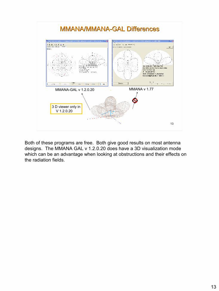
MMANA/MMANA-GAL DifferencesMMANA/MMANA-GAL Differences
MMANA-GAL v 1.2.0.20 MMANA v 1.77
3 D viewer only in V 1.2.0.20
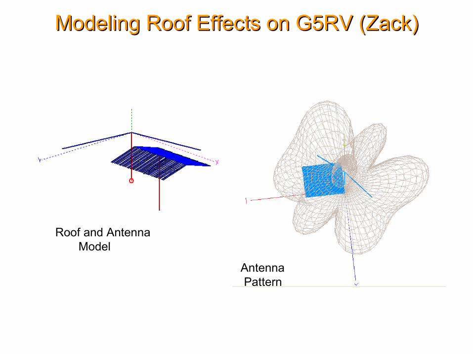
Modeling Roof Effects on G5RV (Zack)Modeling Roof Effects on G5RV (Zack)
Roof and Antenna Model
Antenna Pattern

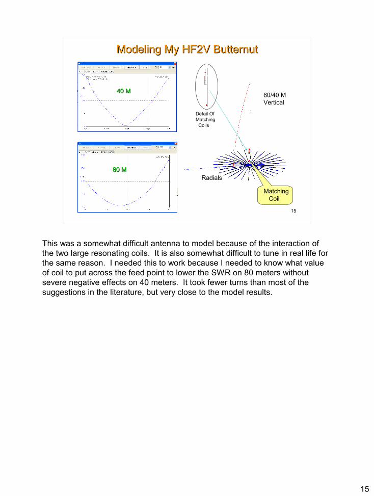
Modeling My HF2V ButternutModeling My HF2V Butternut
80/40 MVertical
Detail OfMatching Coils
40 M40 M
80 M80 M
Matching Coil
Radials
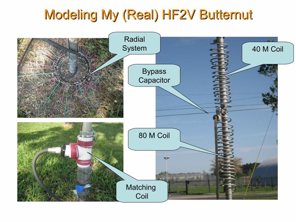
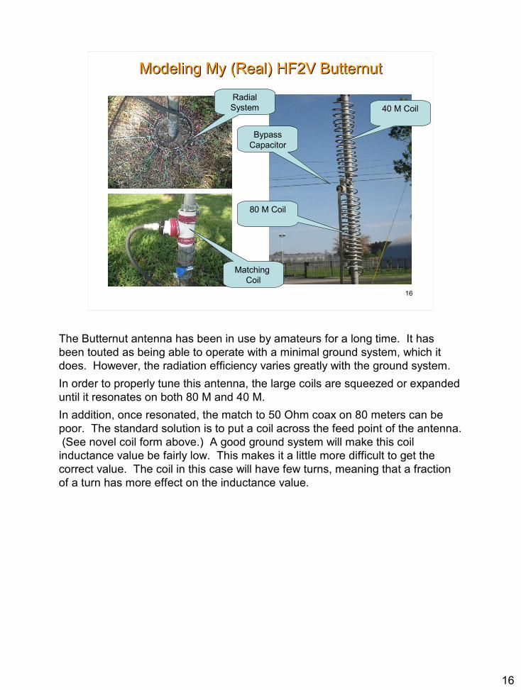
Modeling My (Real) HF2V ButternutModeling My (Real) HF2V Butternut
Bypass Capacitor
80 M Coil
40 M Coil
Matching Coil
Radial System
Radial
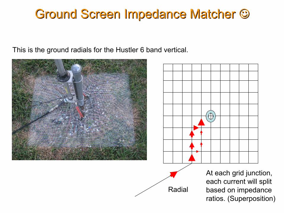
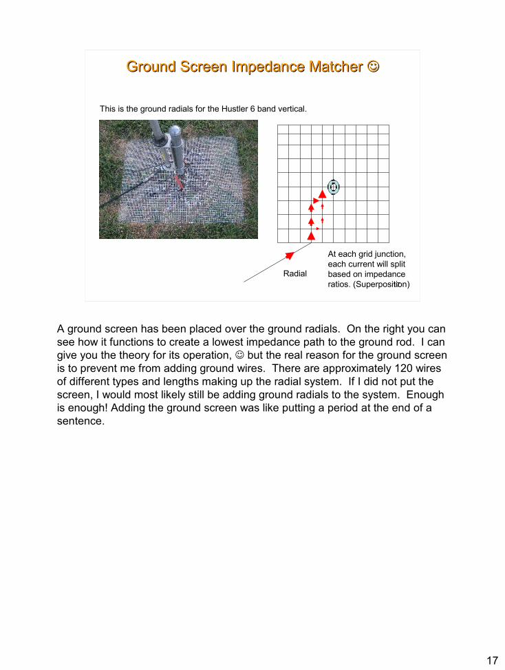
Ground Screen Impedance Matcher Ground Screen Impedance Matcher
At each grid junction,each current will split based on impedance ratios. (Superposition)
This is the ground radials for the Hustler 6 band vertical.
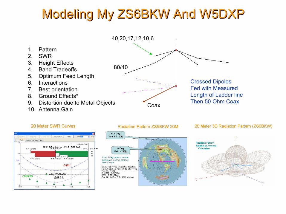
Modeling My ZS6BKW And W5DXPModeling My ZS6BKW And W5DXP
Crossed DipolesFed with MeasuredLength of Ladder lineThen 50 Ohm Coax
80/40
Coax
40,20,17,12,10,6
1. Pattern2. SWR3. Height Effects4. Band Tradeoffs5. Optimum Feed Length6. Interactions7. Best orientation8. Ground Effects*9. Distortion due to Metal Objects10. Antenna Gain
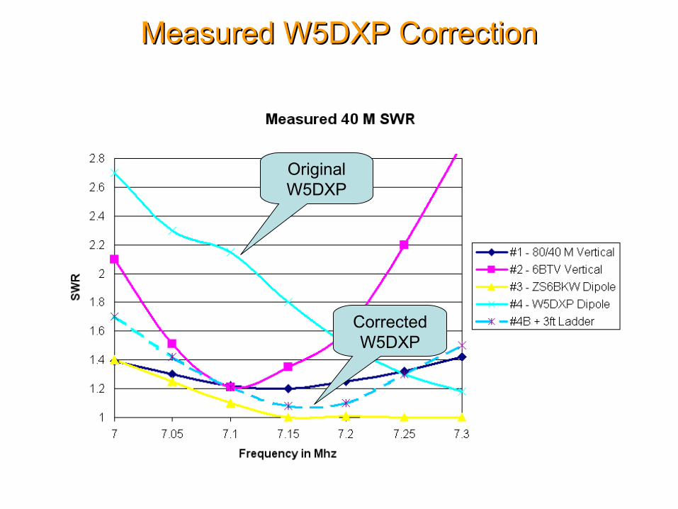
Measured W5DXP CorrectionMeasured W5DXP Correction
OriginalW5DXP
CorrectedW5DXP

Measured W5DXP CorrectionMeasured W5DXP Correction
OriginalW5DXP
CorrectedW5DXP
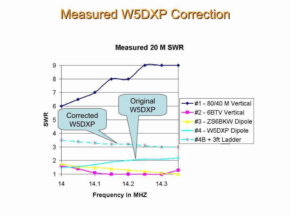
Measured W5DXP CorrectionMeasured W5DXP Correction
OriginalW5DXP
CorrectedW5DXP

Modeling My 2 Meter 6 Element BeamModeling My 2 Meter 6 Element Beam

2 M Vertical Antenna Patterns Over 4 Mhz Frequency Range2 M Vertical Antenna Patterns Over 4 Mhz Frequency Range

Modeling 6 M, 2 M, 70 CM AntennaModeling 6 M, 2 M, 70 CM Antenna
Well, as you can guess, the next step is to see if they will all work on a common boom. This version has the 2M/70CM elements in a vertical configuration, which is appropriate for repeater contacts.
No significant interactions are observed with the three antennas except for 70CM effects from the 2m antenna.
Shown to the left is the patternOf the Moxon with all elementsIn place – Not too bad.
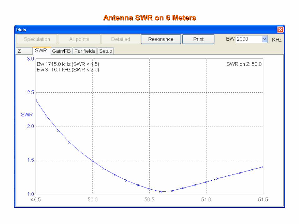
Antenna SWR on 6 MetersAntenna SWR on 6 Meters

Antenna SWR on 2 MetersAntenna SWR on 2 Meters
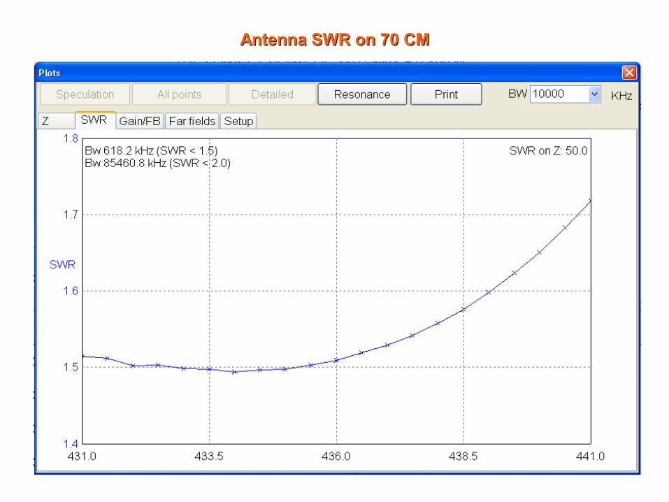
Antenna SWR on 70 CMAntenna SWR on 70 CM

Modeling My 2-Element Phased VerticalModeling My 2-Element Phased Vertical
Gutter anddownspout
Hurricane Fence
Hustler 6 Band Vertical
Weston 4 Band VerticalReflector/Director
Butternut HF2V 80/40 Vertical

Vertical Beam Antenna Pattern on 20 MetersVertical Beam Antenna Pattern on 20 Meters

Vertical Beam Antenna Pattern on 40 MetersVertical Beam Antenna Pattern on 40 Meters
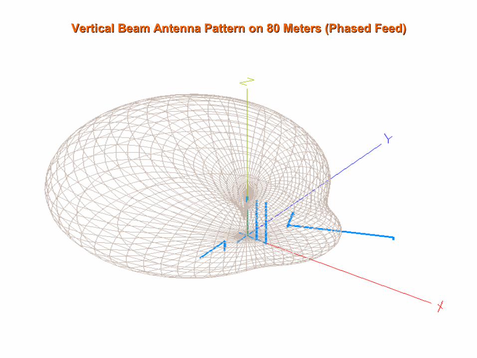
Vertical Beam Antenna Pattern on 80 Meters (Phased Feed)Vertical Beam Antenna Pattern on 80 Meters (Phased Feed)
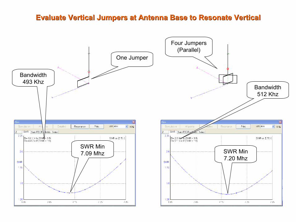
Evaluate Vertical Jumpers at Antenna Base to Resonate VerticalEvaluate Vertical Jumpers at Antenna Base to Resonate Vertical
One Jumper
Four Jumpers (Parallel)
Bandwidth 493 Khz
Bandwidth 512 Khz
SWR Min 7.09 Mhz SWR Min
7.20 Mhz

Modeling My Colinear VHF VerticalModeling My Colinear VHF Vertical
Antenna designed by Don Murray W9VE
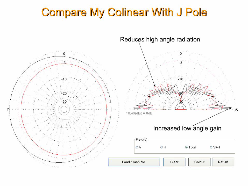
Compare My Colinear With J PoleCompare My Colinear With J Pole
Reduces high angle radiation
Increased low angle gain
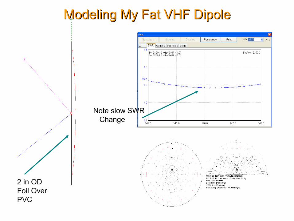
Modeling My Fat VHF DipoleModeling My Fat VHF Dipole
2 in ODFoil OverPVC
Note slow SWR Change
Source Information And ReferencesSource Information And References
http://www.fars.k6ya.org/docs/New-Results-on-Antenna-Impedance-Models-and-Matching.pdfhttp://www.w5ddl.org/files/Zs6bkw_vs_G5rv_20100221_files/frame.htmhttp://www.w5fc.org/files/how-to/j-pole/J-pole%20slides.ppt

1
1
Computer Antenna Modeling Computer Antenna Modeling Simplified – KE5KJDSimplified – KE5KJD
An exposure to the benefits of computer modeling using
software.
Compiled from the Internet for the AARA Ham Radio Club - 2010
Archie asked me a few months ago if I would be interested in presenting some information to the club about antenna modeling. Not being an expert in the subject, I chose the topic “Computer Antenna Modeling Simplified”, thinking that I could present material that I do understand and avoid any complicated questions on the subject. This entire presentation is available on the AARA Club site at http://www.w5ddl.org.This topic has become a high interest topic in the last 10 years because the computers available for personal use have the capacity and speed to perform the many calculations that at one time were done manually.It is much easier to modify and test a computer model than a full sized antenna design, especially at the HF and lower HF frequencies.The typical PC of 1 GHZ and above has more processing power and memory than some of the supercomputers available only to research and government groups in the past.This presentation will show that modeling is one way to try out antenna designs before building and testing them.It doesn’t take long to convince yourself that building antennas with software is more accurate, less time consuming and a heck of lot safer (and cheaper!) than the real thing. However, one must remember the objective --- to have an real antenna system that will allow you to enjoy the hobby on an ongoing basis.
2
2
Antenna Modeling What is it?Antenna Modeling What is it?
Computerized antenna modeling is evaluating the performance of a system that is governed by the laws of physics.
Antenna-modeling programs are computer programs that use mathematics to calculate and predict the electrical performance of an antenna. Modeling usually has its limitations, partly because the mathematical model that we have to describe it can almost never be described in the same detail as the real thing (and especially its environment), and partly because of numerical limitations in the calculating code used or imposed by the developer.
The final limitation is the operator, who enters the data and who interprets the results. In all cases a good deal of knowledge and experience in the field of antennas is required in order to draw the correct conclusions and take the right decisions during the process of modeling. However almost anyone with a computer and data entry skills can select an antenna design of a given type and change it to match their constraints and view the results.
Most computer modeling programs in use today use rather simple calculations on segments of radiators and accumulate its effects on every other segment and in free space. This method is commonly called the “Method of Moments”. Another method uses the differential equations and calculate answers using a “Finite Difference” calculation to arrive at the answer. No matter which method, extreme care must be taken in the numerical calculation, using as much precision as required to get accurate results. Also, the number of segments used depends on the closeness of elements and complexity of the element connections.
3
3
Start With Simple Equations Start With Simple Equations
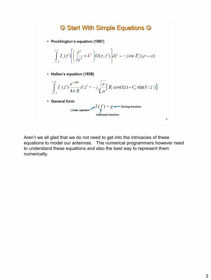
Aren’t we all glad that we do not need to get into the intricacies of these equations to model our antennas. The numerical programmers however need to understand these equations and also the best way to represent them numerically.
4
4
Why Model AntennasWhy Model Antennas
To understand how antennas work. To verify designs from literature. To optimize a design for your particular needs (frequency, height, application). To create a new design. To compare one antenna design against another.To modify the resonant frequency of an existing antenna.To understand the effects of a planned antenna modification.To see the effects of varying the angle (horizontal, vertical) of a dipoleTo determine the feedpoint impedance around the chosen frequencyTo place the antenna(s) at your location.To see the antenna radiation pattern and take – off angle.To view induced currents in metal objectsTo avoid complex manual calculationsFor the pure joy of it …. Like working crossword puzzles.
Antenna modeling is not at all fun unless you get results that satisfy your requirements. It does, however, make one aware of all that needs to be specified and known about our antenna before we can view results that we can use and trust in putting together our own antenna.Many times in modeling antennas I was made aware of why my implementation of someone’s design did not perform as well as the author’s version – mostly due to my lower height of the antenna. It also explained why some antennas, like the colinear W5YI on 20 meters, is such a good high gain antenna, even at low antenna heights.
5
5
Questions Answered By ModelingQuestions Answered By Modeling
1. What is the radiation pattern for a given antenna at my location?2. Will my roof, gutters and clothesline poles affect the pattern?3. What do I need to do to the antenna to optimize it for my favorite portion
of the band (phone, data, cw)?4. How much of the band can I use effectively with or without a tuner.5. How much of a change can I expect if I increase the height from 25 feet
to 45 feet?6. What is the SWR curve over frequency look like at the antenna?7. What is the SWR curve look like at the transmitter end of my feedline?8. Can I place another antenna on the same support without deteriorating
the performance?9. Where should I place another antenna structure in my yard to minimize
its effects (or improve its effects)?10. What SWR at 10 feet results in a given SWR at 40 feet?11. How much of my power is actually delivered to the antenna?12. What losses are introduced by the cable and other elements?13. Which antenna type should I put up in my situation?
NOTE: Modeling can save money, time, and shoe leather.
The questions listed are some of the many reasons we may want to model an antenna BEFORE making changes or putting it up in the air. In addition to the reasons listed, the model can be used to verify observed results, especially when we do not expect the changes we are observing.

6
6
How Software Modeling WorksHow Software Modeling Works
1. Define the geometry of the antenna.2. Define the environment in which the antenna works.3. Define the numerical evaluation parameters (if different from a base set)4. Select the center frequency for the initial antenna evaluation.5. Select the lower and upper bounds for the plots.6. View the results.7. Make modifications, then rerun until you are satisfied with results.8. Sleep on it and start over the next day.
Most antenna modeling programs have extensive libraries of standard antenna designs to choose from, so #1 above is not so bad. Most have also tried to make the data entry as painless as possible, but most fall short of easily referencing antenna elements and placement that the amateur radio operator would like. KE5KJD adds his own elements to a basic library of “antenna parts” and uses these to build new designs.
Many have options to automate step 7 using supplied modification rules and some definition of “success”.
Making a software model primarily involves inputting the definition of our antenna elements. Some programs are better than others at accepting inputs or making changes to portions of the antenna. None I have used are as easy as I think they should be. I want to “build” my element with variable lengths, etc. and keep them in a library of my chosing that I can reference easily into my design. Like, a trap vertical that I can then use on a boom as a dipole or Yagi.Some of the designs I have worked with required many, many iterations to come up with the final design, so ease in modification is a real plus.

7
7
Parts of the Antenna ModelParts of the Antenna Model
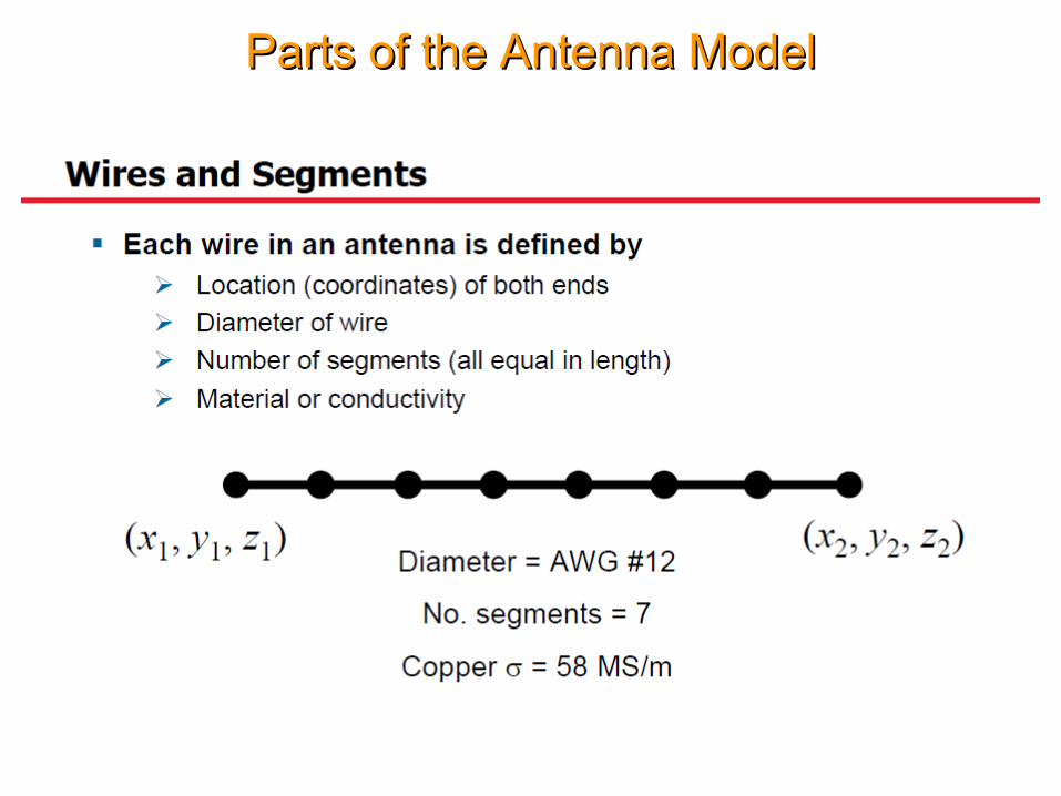
The basic part of antenna design is a wire or cylinder of appropriate dimensions with certain conductivity. The element can be specified in segments or the program can perform segmentation for you.

8
8
Parts of the Antenna ModelParts of the Antenna Model
The source excitation for the antenna is usually placed at the feed point of the antenna. It is also possible to feed the antenna at the end of a transmission line with given parameters.

9
9
Parts of the Antenna ModelParts of the Antenna Model
Loads can be used at any point within an element to represent inductive loading, resistive losses, or traps.

10
10
Which Program Do I Use?Which Program Do I Use?
1. NEC – Numeric Electromagnetics Code2. NEC 2 – Public Domain - Single diameter wires3. 4NEC2 – Free version of NEC 24. EZNEC, EZNEC Pro W7EL – Active ham developer/Sales5. NEC – 4 Latest version from Lawrence Livemore Labs ($250 License)6. MMANA GAL – EZNEC with spreadsheet antenna definition.7. GAL ANA – MININEC 3 and NEC2 calculations. Demo version only, in
active development..
The MININEC versions are adequate for most applications. NEC 4 models most situations, including an accurate ground system. MMANA GAL does not have accurate results near ground but does include variable element diameters and tapered elements. NEC 4 has the most up to date features and is used by antenna design professionals.
You should look up these programs on the internet if you need additional information. KE5KJD uses MMANA GAL because it is free and does a reasonable job of calculating radiation patterns.
My primary experience has been with the MMANA GAL version of MININEC, primarily because it is pretty good at modeling and the price is right – FREE!I have notices several recent antenna articles the use the program. While NEC4 is the current favorite of professional designers, its cost would most likely keep many hams from using it.

11
11
MMANA Antenna Modeling ProgramMMANA Antenna Modeling Program
Author: Makoto (Mako) Mori JE3HHT © 1999-2000Gontcharenko Gary DL2KQ-EU1TT developed and released English versions of MMANA in 2001-2002. Nobuyuki Oba JA7UDE wrote an English user manual in 2001. Software beta testing was provided by a group of fellow amateurs.
Cost: Freeware
MMANA is an antenna analyzing tool based on the moment method introduced in MININEC (Mini Numerical Electromagnetics Code) Version 3. MININEC should not be confused with NEC, which is a large antenna analysis program written in FORTRAN and designed to run on main-frame computers. A graphical user interface also was added that makes MMANA much easier to use than MININEC version it was ported from. (Some portions of later versions of MININEC are written in FORTRAN.)

12
12
MMANA/GAL Program FeaturesMMANA/GAL Program Features
• Both table-based and graphical-based editors for antenna design and definition
• A 3-dimensional graphical antenna viewer that shows antenna elements, element current distributions, and the elemental segmentations used.
• A far field radiation viewer that shows both horizontal and vertical far field radiation patterns (MMANA GAL 1.20 has 3-D far field display)
• A comparator that can be used to compare two or more computation results • An antenna element editor • An antenna wire editor • Tools for defining combinations of pipe or tube elements with stepped
diameters • A user-customizable automatic antenna optimizer capable of optimizing
antenna designs with respect to jX, SWR, Gain, F/B, Elevation, and Current • An antenna optimizer results display table with manual tuning capabilities • Antenna frequency characteristics plotting • An antenna specification file generator • Plus many other things, such as 3-dimensional antenna rotation, antenna
stacking, and frequency scaling
Many times I simply copy the antenna definition file into a notepad text editor to make global changes, which is quicker than modifying elements one by one. I also use this trick to insert pre-defined ground planes, metal objects, and other antennas into the model without manually entering them each time. I then just update the wire count to match.
13
13
MMANA/MMANA-GAL DifferencesMMANA/MMANA-GAL Differences
MMANA-GAL v 1.2.0.20 MMANA v 1.77
3 D viewer only in V 1.2.0.20
Both of these programs are free. Both give good results on most antenna designs. The MMANA GAL v 1.2.0.20 does have a 3D visualization mode which can be an advantage when looking at obstructions and their effects on the radiation fields.

14
14
Modeling Roof Effects on G5RV (Zack)Modeling Roof Effects on G5RV (Zack)
Roof and Antenna Model
Antenna Pattern
Zack was concerned about his G5RV and the possible interaction with his metal roof. A model of the roof was added to the G5rv model and run. It showed some interaction, mostly good, because the metal roof had stronger reflections than the lossy ground and gave some additional gain in the direction opposite the roof.
15
15
Modeling My HF2V ButternutModeling My HF2V Butternut
80/40 MVertical
Detail OfMatching Coils
40 M40 M
80 M80 M
Matching Coil
Radials
This was a somewhat difficult antenna to model because of the interaction of the two large resonating coils. It is also somewhat difficult to tune in real life for the same reason. I needed this to work because I needed to know what value of coil to put across the feed point to lower the SWR on 80 meters without severe negative effects on 40 meters. It took fewer turns than most of the suggestions in the literature, but very close to the model results.
16
16
Modeling My (Real) HF2V ButternutModeling My (Real) HF2V Butternut
Bypass Capacitor
80 M Coil
40 M Coil
Matching Coil
Radial System
The Butternut antenna has been in use by amateurs for a long time. It has been touted as being able to operate with a minimal ground system, which it does. However, the radiation efficiency varies greatly with the ground system.In order to properly tune this antenna, the large coils are squeezed or expanded until it resonates on both 80 M and 40 M.In addition, once resonated, the match to 50 Ohm coax on 80 meters can be poor. The standard solution is to put a coil across the feed point of the antenna. (See novel coil form above.) A good ground system will make this coil inductance value be fairly low. This makes it a little more difficult to get the correct value. The coil in this case will have few turns, meaning that a fraction of a turn has more effect on the inductance value.
17
17Radial
Ground Screen Impedance Matcher Ground Screen Impedance Matcher
At each grid junction,each current will split based on impedance ratios. (Superposition)
This is the ground radials for the Hustler 6 band vertical.
A ground screen has been placed over the ground radials. On the right you can see how it functions to create a lowest impedance path to the ground rod. I can give you the theory for its operation, but the real reason for the ground screen is to prevent me from adding ground wires. There are approximately 120 wires of different types and lengths making up the radial system. If I did not put the screen, I would most likely still be adding ground radials to the system. Enough is enough! Adding the ground screen was like putting a period at the end of a sentence.
18
18
Modeling My ZS6BKW And W5DXPModeling My ZS6BKW And W5DXP
Crossed DipolesFed with MeasuredLength of Ladder lineThen 50 Ohm Coax
80/40
Coax
40,20,17,12,10,6
1. Pattern2. SWR3. Height Effects4. Band Tradeoffs5. Optimum Feed Length6. Interactions7. Best orientation8. Ground Effects*9. Distortion due to Metal Objects10. Antenna Gain
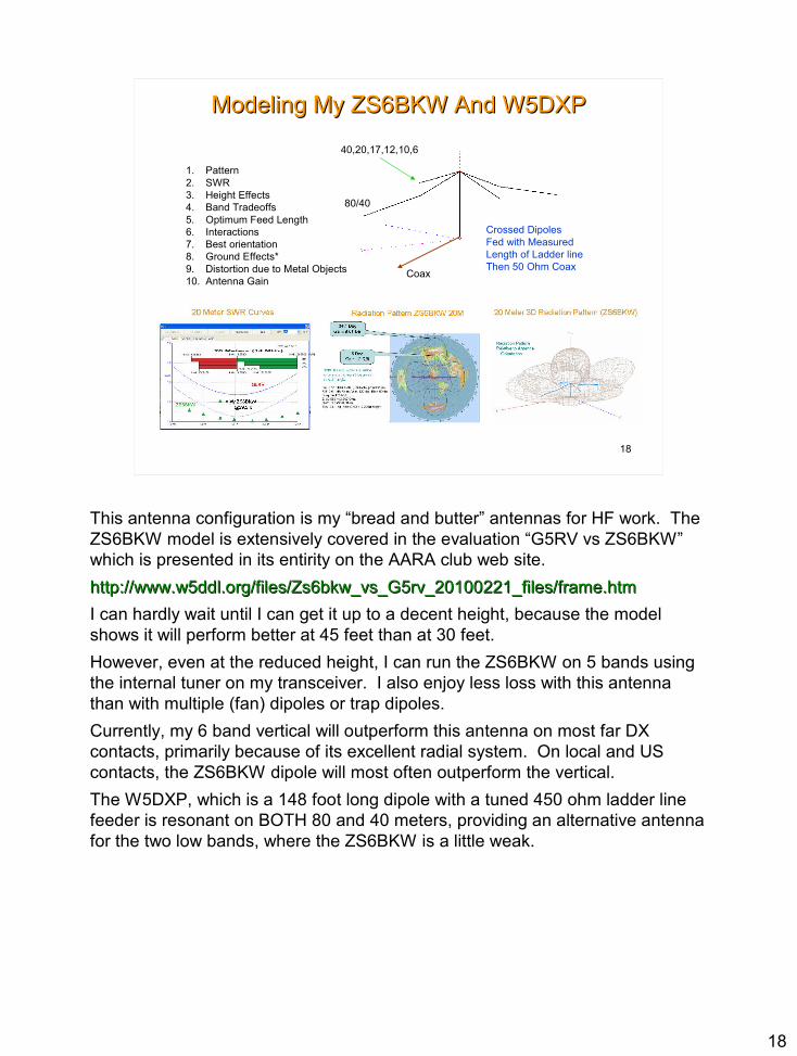
This antenna configuration is my “bread and butter” antennas for HF work. The ZS6BKW model is extensively covered in the evaluation “G5RV vs ZS6BKW” which is presented in its entirity on the AARA club web site.http://www.w5ddl.org/files/Zs6bkw_vs_G5rv_20100221_files/frame.htmhttp://www.w5ddl.org/files/Zs6bkw_vs_G5rv_20100221_files/frame.htmI can hardly wait until I can get it up to a decent height, because the model shows it will perform better at 45 feet than at 30 feet.However, even at the reduced height, I can run the ZS6BKW on 5 bands using the internal tuner on my transceiver. I also enjoy less loss with this antenna than with multiple (fan) dipoles or trap dipoles.Currently, my 6 band vertical will outperform this antenna on most far DX contacts, primarily because of its excellent radial system. On local and US contacts, the ZS6BKW dipole will most often outperform the vertical.The W5DXP, which is a 148 foot long dipole with a tuned 450 ohm ladder line feeder is resonant on BOTH 80 and 40 meters, providing an alternative antenna for the two low bands, where the ZS6BKW is a little weak.

19
19
Measured W5DXP CorrectionMeasured W5DXP Correction
OriginalW5DXP
CorrectedW5DXP
This graph shows actual SWR measurements of all my antenna HF systems. The W5DXP antenna as measured when first put up had a resonance too high on this band. The computed sensitivity to a change in ladder line length and antenna length from the model indicated that a longer ladder line would improve the SWR on 40 meters and also on 80 meters. The ladder length was changed by about 32 inches to obtain the improvement shown, as predicted by the model. It also showed that the antenna length would need changing to maintain the resonance on 80 meters. Since I wanted a slight decrease in resonant frequency on 80 M to get closer to the DX window at 3.79 Mhz, I opted to only change the ladder length.by How was the sensitivity determined? Simply recording the resonant frequency of the antenna at the nominal measurement, and with the antenna length shortened by .5 meters and elongated by .5 meters. The same was done by changing the ladder line length by .5 meters shorter and longer, recording the new resonant frequency each time. This sensitivity number can be then computed in cycles changed in megahertz per inch.

20
20
Measured W5DXP CorrectionMeasured W5DXP Correction
OriginalW5DXP
CorrectedW5DXP
This graph shows the change in resonant frequency on 80 meters, which is better within the DX window. I may in the future decrease the antenna length and increase the ladder line length to move the resonant frequency to about 3.92 MHZ on 80 M because I check in to NET frequencies in this range. For the time being, I will leave it as it is.

21
21
Measured W5DXP CorrectionMeasured W5DXP Correction
OriginalW5DXP
CorrectedW5DXP
This graph shows the change on 20 M, which indicates that the change made things worse on this band. (as expected from the modeling). It is still barely usable on this band but certainly not optimal.

22
22
Modeling My 2 Meter 6 Element BeamModeling My 2 Meter 6 Element Beam
This antenna is mounted on a TV push up pole with a TV rotator. It lets me easily get into Baton Rouge and Abbeville repeaters. It is evolving into a mulltiband 2M, 440, and 6M antenna, as seen in the models to follow. The boom is a 1 x 2 wood beam with spar varnish left over from a previous project.The elements are straightened copper tubing cut from a 50 ft roll of refrigerator tubing, which is lighter and less expensive than solid wire. Aluminum tubes would work nearly as well.
23
23
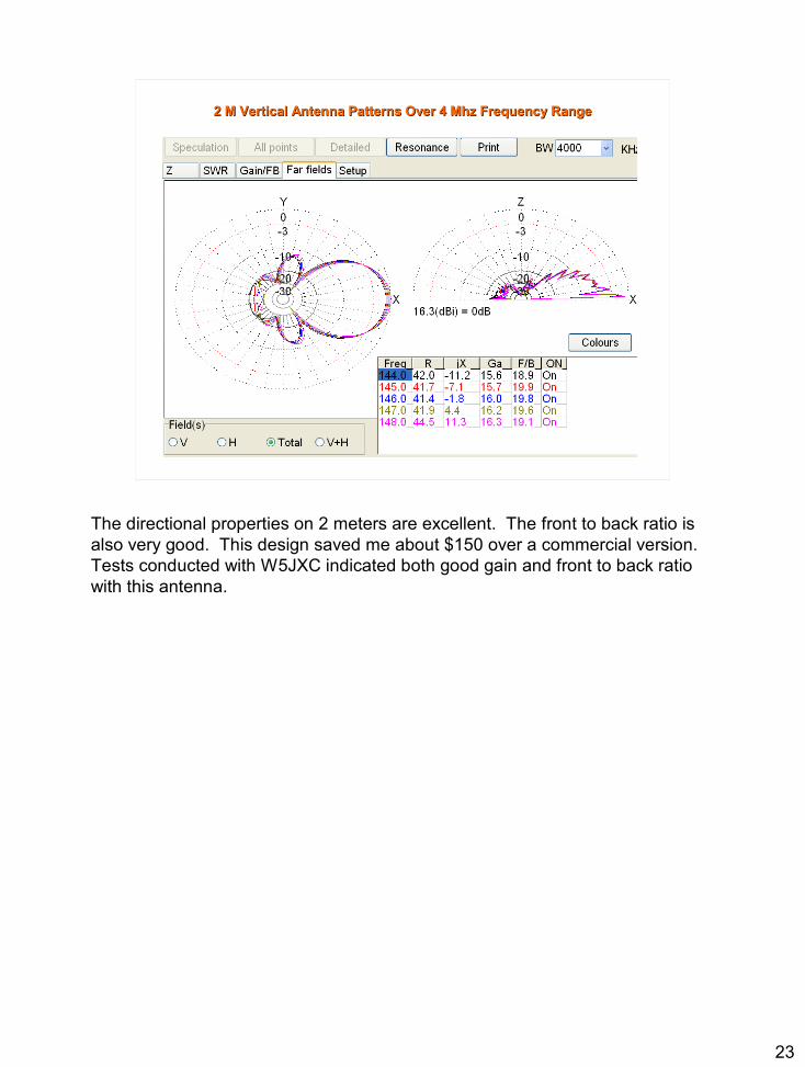
2 M Vertical Antenna Patterns Over 4 Mhz Frequency Range2 M Vertical Antenna Patterns Over 4 Mhz Frequency Range
The directional properties on 2 meters are excellent. The front to back ratio is also very good. This design saved me about $150 over a commercial version. Tests conducted with W5JXC indicated both good gain and front to back ratio with this antenna.
24
24
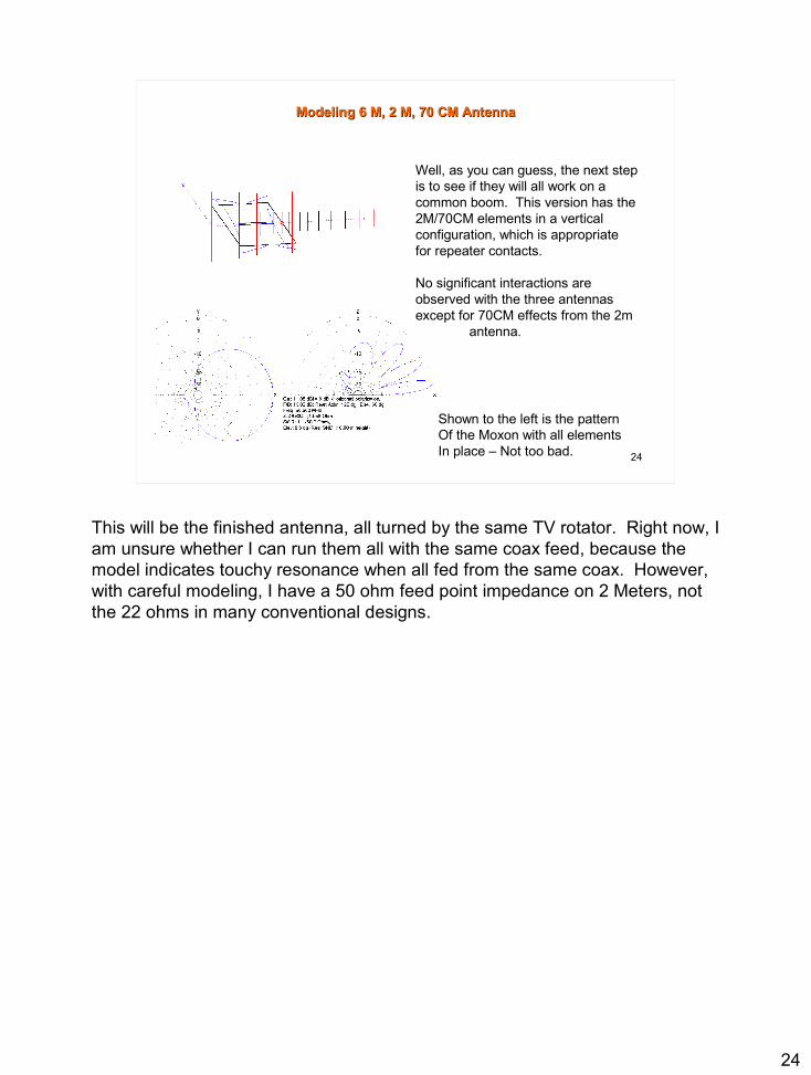
Modeling 6 M, 2 M, 70 CM AntennaModeling 6 M, 2 M, 70 CM Antenna
Well, as you can guess, the next step is to see if they will all work on a common boom. This version has the 2M/70CM elements in a vertical configuration, which is appropriate for repeater contacts.
No significant interactions are observed with the three antennas except for 70CM effects from the 2m antenna.
Shown to the left is the patternOf the Moxon with all elementsIn place – Not too bad.
This will be the finished antenna, all turned by the same TV rotator. Right now, I am unsure whether I can run them all with the same coax feed, because the model indicates touchy resonance when all fed from the same coax. However, with careful modeling, I have a 50 ohm feed point impedance on 2 Meters, not the 22 ohms in many conventional designs.
25
25
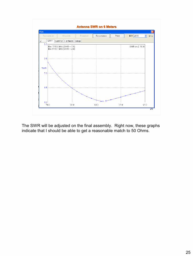
Antenna SWR on 6 MetersAntenna SWR on 6 Meters
The SWR will be adjusted on the final assembly. Right now, these graphs indicate that I should be able to get a reasonable match to 50 Ohms.

26
26
Antenna SWR on 2 MetersAntenna SWR on 2 Meters

27
27
Antenna SWR on 70 CMAntenna SWR on 70 CM

28
28
Modeling My 2-Element Phased VerticalModeling My 2-Element Phased Vertical
Gutter anddownspout
Hurricane Fence
Hustler 6 Band Vertical
Weston 4 Band VerticalReflector/Director
Butternut HF2V 80/40 Vertical
This is the current configuration of my verticals. I am attempting to use two of the multiband trap verticals as a two element system, one fed antenna with the second used as a reflector. Maximum gain improvement in the model shows about 3 DB gain. So far, I have measured only 2+ DB. Also, front to back in the model is much better than what I observe. Most of this is due to the lack of good measuring equipment and some is because my signal source is within the local near field zone of the antennas.Using received signals as an indicator is also difficult because the signals vary much more than the improvement I expect to see. However, extensive A/B testing over time verifies the small 2 db improvement.As a side note, a full size (12 gauge copper wire inside a fiberglas fishing pole) outperforms the trap vertical on 20 meters by about 1-2 db.I also have a saved model which includes my push up metal poles for the VHF antennas so that interactions between antenna systems can be estimated. When originally locating the 2 Meter push up pole, strong interactions were noted on 40 M because the pole was near resonant on 40 M. The model indicated that I needed to move the 2 M pole about 40 feet to minimize the interaction. This was before pouring the concrete footing for the mast.

29
29
Vertical Beam Antenna Pattern on 20 MetersVertical Beam Antenna Pattern on 20 Meters
30
30
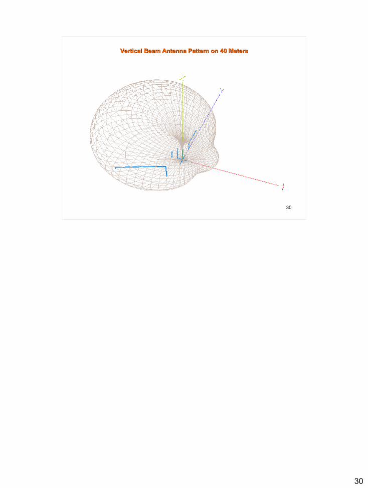
Vertical Beam Antenna Pattern on 40 MetersVertical Beam Antenna Pattern on 40 Meters
31
31
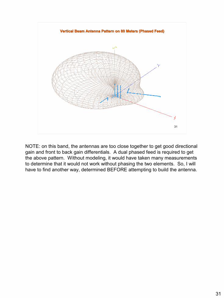
Vertical Beam Antenna Pattern on 80 Meters (Phased Feed)Vertical Beam Antenna Pattern on 80 Meters (Phased Feed)
NOTE: on this band, the antennas are too close together to get good directional gain and front to back gain differentials. A dual phased feed is required to get the above pattern. Without modeling, it would have taken many measurements to determine that it would not work without phasing the two elements. So, I will have to find another way, determined BEFORE attempting to build the antenna.

32
32
Evaluate Vertical Jumpers at Antenna Base to Resonate VerticalEvaluate Vertical Jumpers at Antenna Base to Resonate Vertical
One Jumper
Four Jumpers (Parallel)
Bandwidth 493 Khz
Bandwidth 512 Khz
SWR Min 7.09 Mhz SWR Min
7.20 Mhz
The question came up on the design as to whether the antenna system could be tuned using switched jumpers to ground. The above model was constructed which indicated that it would work on 40 Meters. In addition, if the jumpers were paralleled, then as the number of jumpers was increased, we also got a small bonus in increased bandwidth because of the thicker wire cage at the bottom of the antenna. The antenna was changed for 20 Meters and the results were similar, with shorter jumpers required.It also led to a scheme of tuning the antenna to the higher end of its range for the short jumper case, and to the low end of the band using the longer jumper, and simply connecting more or less variable length jumpers in parallel for the tuning. The plan is to use 7 relays (Cat 5 control Cable) and a bank of binary switches to parallel the jumpers from the shack. This will allow tuning the vertical with 128 different combinations of wires (Not all will be useful). The lowest frequency jumper may need to be a coil if the antenna is to be used on 80 meters (not likely). The parallel combinations will allow tuning on multiple bands, 10 M – 40 M.Testing of this arrangement was done in two ways. One was to receive steady signals on the band while inserting and removing the jumpers on the reflector. The second way was to transmit through the antenna system (exciting the driven element) and looking at the signal on a field strength meter. It was much easier to measure the attenuation on the back side of the antenna because the F/B ratio of the antenna is much higher (~8-10db) than the forward gain difference (~2db)
33
33
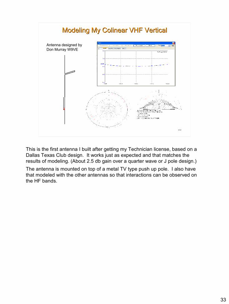
Modeling My Colinear VHF VerticalModeling My Colinear VHF Vertical
Antenna designed by Don Murray W9VE
This is the first antenna I built after getting my Technician license, based on a Dallas Texas Club design. It works just as expected and that matches the results of modeling. (About 2.5 db gain over a quarter wave or J pole design.)The antenna is mounted on top of a metal TV type push up pole. I also have that modeled with the other antennas so that interactions can be observed on the HF bands.

34
34
Compare My Colinear With J PoleCompare My Colinear With J Pole
Reduces high angle radiation
Increased low angle gain
This shows another useful feature of MMANA GAL, where you can compare one antenna pattern against another. This one gives you a sense of why the colinear is a good choice for a base antenna. It goes almost twice as far on transmit or receive. This is not obvious from looking at the antenna pattern by itself.

35
35
Modeling My Fat VHF DipoleModeling My Fat VHF Dipole
2 in ODFoil OverPVC
Note slow SWR Change
This will be the antenna to bring to special events. It is not bothered much by close objects or people, and has a very stable SWR to match a hand-held or mobile transmitter. Howerer, the design is not much better than the Arrow antenna or any other half wave VHF antenna.

36
36
Source Information And ReferencesSource Information And References
http://www.fars.k6ya.org/docs/New-Results-on-Antenna-Impedance-Models-and-Matching.pdfhttp://www.w5ddl.org/files/Zs6bkw_vs_G5rv_20100221_files/frame.htmhttp://www.w5fc.org/files/how-to/j-pole/J-pole%20slides.ppt
Sources will be added as time permits.

37
37
Click to add title• Click to add an outline