computer and digital system architecturepersonal.stevens.edu/~bmcnair/ee810a-s11/week12-810.pdf ·...
TRANSCRIPT

EE810A4/18/2011
Copyright ©2011Stevens Institute of Technology - All rights reserved 1-1/34
Computer and Digital System Architecture
EE/CpE-810-A
Bruce [email protected]

EE810A4/18/2011
Copyright ©2011Stevens Institute of Technology - All rights reserved 1-2/34
Week 12
Embedded ARM applications
Furber Ch. 13

EE810A4/18/2011
Copyright ©2011Stevens Institute of Technology - All rights reserved 1-3/34
System-on-a-chip concept
CPU MMU memory
coprocessor(s) I/O interface9s)specialpurposehardware
chip
peripherals memory

EE810A4/18/2011
Copyright ©2011Stevens Institute of Technology - All rights reserved 1-4/34
Ruby II advanced communication controller
ARMcore
clockcontrol 512x32
SRAMinterruptcontroller
counter/timer
hostFIFOs(16x8)
serialFIFOs(16x8)
PCMCIAhost
interface
UART1
UART1
high-speedserial I/F
parallelI/F 1,2,3,4
serialcontroller
externalbus
control
parallelinterface 0
I/Omodeselect
control
address (22)
data (8/16/32)
I2C
8 data bits& controlserial
clock
externalinterrupts (3)

EE810A4/18/2011
Copyright ©2011Stevens Institute of Technology - All rights reserved 1-5/34
Ruby II advanced communication controller
750 W150 AAll circuits (including timers and oscillators) stopped. Some interrupts return system to on-line mode
Stop
7.5 mW1.5 mAOther than oscillators and timers, all circuitry stopped. Some interrupts change system to on-line mode
Sleep
40 mW7.9 mAARM core runs with 1-64 wait states, all other circuits run at full speed. Interrupts cause system to change to on-line mode
Command150 mW30 mAAll circuits clocked at full speedOn-linePowerCurrentFunctionMode
Power consumption at 5V, 20 MHz
80-pin TQFP package
Ruby II available in 144 and 176-pin TQFPas standard communications processor

EE810A4/18/2011
Copyright ©2011Stevens Institute of Technology - All rights reserved 1-6/34
Typical VIP (VLSI ISDN Subscriber Processor) system configuration
ISDNsubscriberprocessor
driver
power ROM
RAM
K E YP A D
display
V24 interface
S0 ISDN interface
volume
hands-free
hook switch
EE810A4/18/2011
Copyright ©2011Stevens Institute of Technology - All rights reserved 1-7/34
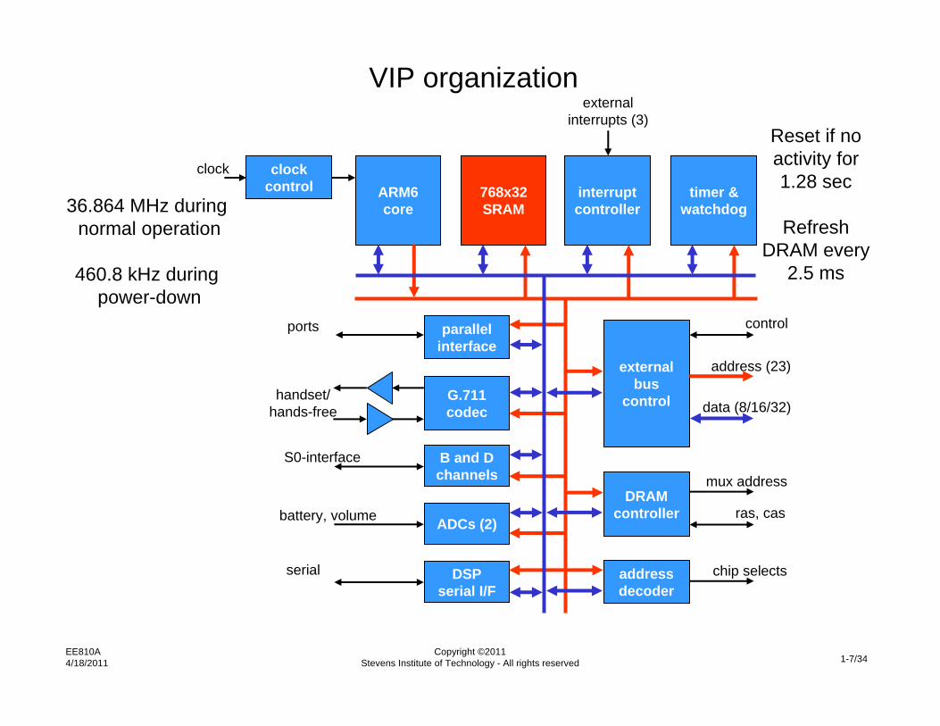
VIP organization
ARM6core
clockcontrol 768x32
SRAMinterruptcontroller
timer &watchdog
parallelinterface
DRAMcontroller
externalbus
control
addressdecoder
G.711codec
B and Dchannels
ADCs (2)
DSPserial I/F
ras, cas
mux address
chip selects
control
address (23)
data (8/16/32)
externalinterrupts (3)
clock
ports
handset/hands-free
S0-interface
battery, volume
serial
36.864 MHz during normal operation
460.8 kHz during power-down
Reset if no activity for 1.28 sec
Refresh DRAM every
2.5 ms
EE810A4/18/2011
Copyright ©2011Stevens Institute of Technology - All rights reserved 1-8/34
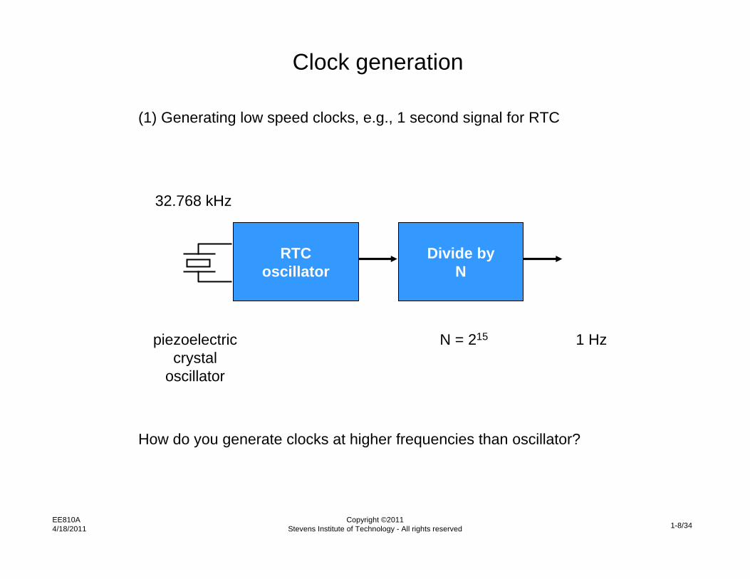
Clock generation
RTCoscillator
32.768 kHz
(1) Generating low speed clocks, e.g., 1 second signal for RTC
piezoelectriccrystal
oscillator
Divide byN
1 HzN = 215
How do you generate clocks at higher frequencies than oscillator?

EE810A4/18/2011
Copyright ©2011Stevens Institute of Technology - All rights reserved 1-9/34
Clock generation
System clockoscillator
fref
(2) Generating high speed clocks, e.g., processor clock at 50 MHz
piezoelectriccrystal
oscillator
M/N PLL
M/N x fref

EE810A4/18/2011
Copyright ©2011Stevens Institute of Technology - All rights reserved 1-10/34
Clock generation
(2) Generating high speed clocks, e.g., processor clock at 50 MHz
System clockoscillator
fref
M/N PLL
fref fout = fref x M

EE810A4/18/2011
Copyright ©2011Stevens Institute of Technology - All rights reserved 1-11/34
Clock generation
(2) Generating high speed clocks, e.g., processor clock at 50 MHz
System clockoscillator
fref
M/N PLL
voltage controlledoscillator (VCO)fref fout

EE810A4/18/2011
Copyright ©2011Stevens Institute of Technology - All rights reserved 1-12/34
Clock generation
(2) Generating high speed clocks, e.g., processor clock at 50 MHz
System clockoscillator
fref
M/N PLL
voltage controlledoscillator (VCO)LPFfref fout

EE810A4/18/2011
Copyright ©2011Stevens Institute of Technology - All rights reserved 1-13/34
Clock generation
(2) Generating high speed clocks, e.g., processor clock at 50 MHz
System clockoscillator
fref
M/N PLL
voltage controlledoscillator (VCO)LPFphase
comparatorfref fout

EE810A4/18/2011
Copyright ©2011Stevens Institute of Technology - All rights reserved 1-14/34
Clock generation
(2) Generating high speed clocks, e.g., processor clock at 50 MHz
System clockoscillator
fref
M/N PLL
voltage controlledoscillator (VCO)LPFphase
comparator
divide byM
fref fout = fref x M

EE810A4/18/2011
Copyright ©2011Stevens Institute of Technology - All rights reserved 1-15/34
Clock generation
(2) Generating high speed clocks, e.g., processor clock at 50 MHz
System clockoscillator
fref
M/N PLL
voltage controlledoscillator (VCO)LPFphase
comparator
divide byM
fref
fout = fref x M/Ndivide byN
fref/N

EE810A4/18/2011
Copyright ©2011Stevens Institute of Technology - All rights reserved 1-16/34
Clock generation
(2) Generating high speed clocks, e.g., processor clock at 50 MHz
System clockoscillator
fref
M/N PLL
voltage controlledoscillator (VCO)LPFphase
comparator
divide byM
fout = fref x M/N
divide byN
fref
fref x M

EE810A4/18/2011
Copyright ©2011Stevens Institute of Technology - All rights reserved 1-17/34
Typical GSM handset architecture
K E YP A D
VWS22100
radiomodule
ROM
RAM
eepromSIMcard
LCD
IrDA
speaker
microphone
ringer

EE810A4/18/2011
Copyright ©2011Stevens Institute of Technology - All rights reserved 1-18/34
GSM handset power management
• Power down most circuitry (digital, analog, RF) between calls, except to periodically listen on control channel for calls
• Slow down clocks in idle mode
• Pulse-width modulate battery charging circuitry for optimum operation
• Use A/Ds to monitor battery temperature and change/discharge voltage

EE810A4/18/2011
Copyright ©2011Stevens Institute of Technology - All rights reserved 1-19/34
OneC VWS22100 GSM chip organizationJTAG
test/debugARM7TDMI
coreinterruptcontroller
bootROM
UART1
UART2/IrDA
high-speedserial I/F(2)
SIM I/F
RTC
externalbus
control
ADC
keypadscanner
GPIOPWM
powermanager
dataRAM
dataROM
config./status
interruptcontroller
memorycontroller
Oak DSPcore
programRAM
programROM
hard
war
eco
proc
s
DSP radioportradio I/F
audio I/F PCM I/F
(6)
(13)
(20)
DSPsubsystem
ARM
bus
DSP
bus
(6)
(4)
(5)
(4)
cntrl (6)
32 kHz
addr (20)
data (16)
(7)
(10)
(11)
• GSM protocol stack• user interface• power management• peripheral I/O• data applications
• Voice coding• equalization• channel coding• echo cancellation• noise suppression• voice recognition• data compression

EE810A4/18/2011
Copyright ©2011Stevens Institute of Technology - All rights reserved 1-20/34
Bluetooth networking
Piconetmaster
Piconetslaves
Ad-hoc piconet~10 cm – 10 m range2 – 8 stationsCommon hopping sequence and synchronized clocks

EE810A4/18/2011
Copyright ©2011Stevens Institute of Technology - All rights reserved 1-21/34
Bluetooth networking
Scatternet made of multiple piconets
EE810A4/18/2011
Copyright ©2011Stevens Institute of Technology - All rights reserved 1-22/34
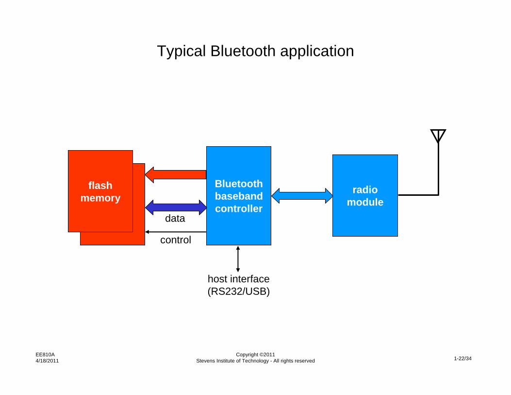
Typical Bluetooth application
flashmemory
Bluetoothbasebandcontroller
radiomodule
host interface(RS232/USB)
data
control

EE810A4/18/2011
Copyright ©2011Stevens Institute of Technology - All rights reserved 1-23/34
Ericsson-VLSI Bluetooth Baseband Controller organization
clockcontrol ARM7TDMI
core4 kB
I-cacheinternal
ROM16K x 32SRAM
externalbus
control
counters/timers
interruptcontroller
I/Omodeselect
USBI/F
I2C I/F
UART 1,2,3
FIFOsEBCblock
clock
JTAGsignals (5)
radio interface
data (8/16)
address (20)
control
Ericcson Bluetooth Core• link controller• packet handling• radio interface

EE810A4/18/2011
Copyright ©2011Stevens Institute of Technology - All rights reserved 1-24/34
Bluetooth chip power
Clock oscillators are stoppedStop
750 W300 AARM7TDMI is stopped, power state of other circuits is programmable
SleepARM7TDMI core runs with wait states, Command
75 mW30 mAAll circuits clocked at full speedOn-linePowerCurrentFunctionMode
Power consumption at 2.5V, 40 MHz MHz

EE810A4/18/2011
Copyright ©2011Stevens Institute of Technology - All rights reserved 1-25/34
Ericcson Bluetooth chip
approx.4.5 mm
EE810A4/18/2011
Copyright ©2011Stevens Institute of Technology - All rights reserved 1-26/34
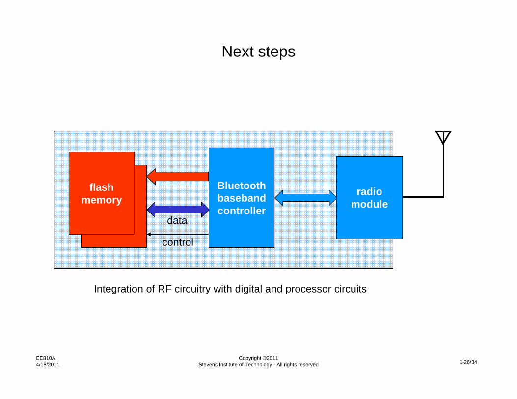
Next steps
flashmemory
Bluetoothbasebandcontroller
radiomodule
data
control
Integration of RF circuitry with digital and processor circuits

EE810A4/18/2011
Copyright ©2011Stevens Institute of Technology - All rights reserved 1-27/34
Typical ARM7500 system organization
ARM7500
ras[
3:0]
DR
AM
DR
AM
DR
AM
DR
AM
DR
AM
DR
AM
DR
AM
DR
AM
DR
AM
DR
AM
DR
AM
DR
AM
DR
AM
DR
AM
DR
AM
DR
AM
DR
AM
DR
AM
DR
AM
DR
AM
DR
AM
DR
AM
DR
AM
DR
AM
DR
AM
DR
AM
DR
AM
DR
AM
DR
AM
DR
AM
DR
AM
DR
AM
DR
AM
RO
M
DR
AM
RO
M
I/Omodule
I/Omodule
moduleselectskeyboard
& mouse
inte
rrupt
s
analoginputs
analogsound vi
deo
RA[
11:0
]
cas[3:0]
D[31:0]
LA[28:0]
BD[15:0]
Functions included:
CPUFloating point co-processorVideo and sound I/FMemory and peripheral controller
nearly complete PC function
Applications• Acorn RISC PC• Video set top box

EE810A4/18/2011
Copyright ©2011Stevens Institute of Technology - All rights reserved 1-28/34
ARM7500 chip
approx8.5 mm

EE810A4/18/2011
Copyright ©2011Stevens Institute of Technology - All rights reserved 1-29/34
The Psion Series 5MX PDA
EE810A4/18/2011
Copyright ©2011Stevens Institute of Technology - All rights reserved 1-30/34
640 x 240LCD
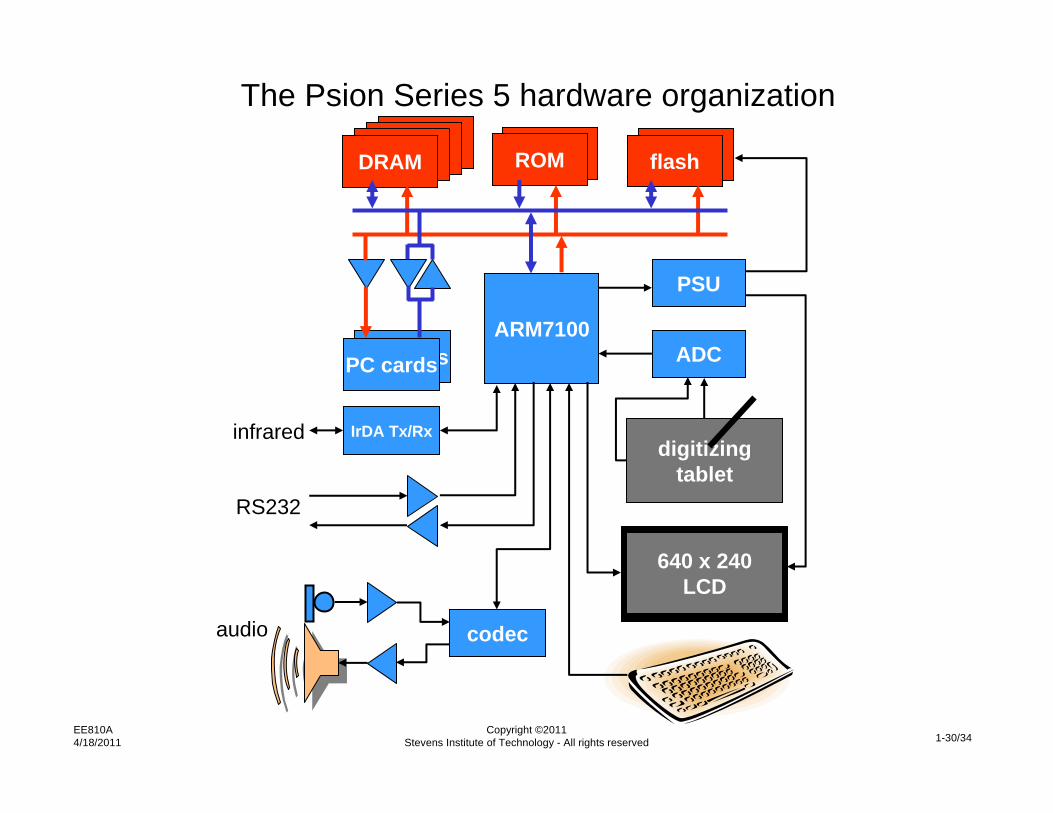
The Psion Series 5 hardware organizationDRAMDRAMDRAMDRAM ROMROM flashflash
ARM7100
PSU
ADC
digitizingtablet
640 x 240LCD
codec
PC cardsPC cards
IrDA Tx/Rx
audio
RS232
infrared

EE810A4/18/2011
Copyright ©2011Stevens Institute of Technology - All rights reserved 1-31/34
ARM7100 organization
MMU ARM7core
8 kbytecache
LCDcontroller
interruptcontroller
externalbus
control
DRAMcontroller
expansion
PSU control
counter/timers
FIFOs
powermgmt
UART
codec I/F
sync serial
parallel I/O
RTCosc
clock PLL
ARM710a
32.768 kHz
3.6864 MHz
AMBA
WE, OE (2)
RAS, CAS (8)
DRA (13)
data (32)
address (28)
control

EE810A4/18/2011
Copyright ©2011Stevens Institute of Technology - All rights reserved 1-32/34
ARM7100 chip

EE810A4/18/2011
Copyright ©2011Stevens Institute of Technology - All rights reserved 1-33/34
SA-1100 organization instruction
MMUinstruction
cacheStrongARM
core data
cach
e
min
i-cac
he
dataMMU
read bufferwrite buffer
memory& PCMCIAbridgeDMA
controlLCD
control
clockPLL
RTCosc
GPI/O
powermanager
resetcontrol
OStimer
RTC
interruptcontrol serial 0
serial 1
serial 2
serial 3
serial 4
CPU core
codec (4)
UART (2)
IrDA (2)
SDLC (2)
USB (2)
control
address (26)data (32)
system bus
peripheral bus
reset (2)
battery (3)
I/O pins (28)
32.768 kHz
3.6864 MHz
LCD (5)

EE810A4/18/2011
Copyright ©2011Stevens Institute of Technology - All rights reserved 1-34/34
SA-1100 chip
approx9 mm