computer-aided real-time kinematic global...
TRANSCRIPT

COMPUTER-AIDED REAL-TIME KINEMATIC GLOBAL POSITIONING SYSTEM POSITIONING TECHNIQUE FOR DEFORMATION
MEASUREMENT AND ANALYSIS
LEE CHEH HANG
UNIVERSITI TEKNOLOGI MALAYSIA

iii
To my beloved family who unselfishly supported me throughout the entire endeavour
and those who inspired me. They make it all worthwhile.

iv
ACKNOWLEDGEMENT
There are many people I would like to recognise for their help and support
with my research. Without them, this thesis would never have been possible for me.
First and foremost, I would like to convey my special thanks to my supervisor
Prof. Dr. Halim Setan for accepting me as his student, particularly that he had three
other researches on hand at that moment. My sincere gratitude also goes to his
patient guidance and constructive suggestions throughout the entire research.
Next, I would like to thank my best friends who provided many idea and
support for this research. Thank you Mr. Kee, Madam Chong, Miss Teong, Miss Lee,
Mr. Shu, Mr. Voon, Mr. Sharuddin and Madam Suraya. I am deeply indebted to your
kindness and help.
Besides, I would like to acknowledge everyone who provided the technical
support for this research. Thanks to Mr. Abu Bakar (Faculty of Civil Engineering),
Mr. Soeb (Geodesy Section, Department of Survey and Mapping, Malaysia), Mr.
Nomy (Trimble Singapore), Mr. Lim (Global-trak System) and Mr. Bakri (Geodesy
Laboratory, Faculty of Geoinformation Science and Engineering) for their help and
kindness.
Lastly, I would like to express my deepest appreciation to my beloved family
who have always unselfishly given me the proper guidance, encouragement and
moral support throughout not only the research, but also my entire life. I love you all.

v
ABSTRACT
Scientific justification and technical feasibility of using Real-Time Kinematic
Global Positioning System (RTK-GPS) positioning as the technique in recording the
responses (in term of coordinate / position) of deformable structures have been
proven very promising. The major advantages are the real-time measurement (either
online or offline) and direct measurement of relative displacement. Nevertheless, the
research, through the sampled data, shows the need of additional steps to handle the
possible errors in direct employment of manufacturers’ RTK positioning solution for
deformation monitoring. In addition, most of the further applications such as online,
automated, continuous, etc., however, have to be self customized and developed. The
sampled data comprise short baseline (1.8km, collected in Universiti Teknologi
Malaysia) and medium length baseline (27.7km, provided by Geodesy Section,
Department of Survey and Mapping, Malaysia). The research thus suggests an
additional approach for RTK positioning integrity monitoring and deformation
detection. The RTK positioning integrity monitoring includes error identification,
outlier filtering and reference station stability checking. The essence of the approach
is the Normal Point technique as well as the Local Threshold and Global Threshold.
Reference for Local Tolerance and Global Tolerance are also discussed. To get the
additional approach running more efficiently in one single system, prototype
software, Sparrow, was developed in Visual Basic environment and by deploying the
Trimble bundled software, which are Trimble GPS Configurator and Trimble
Reference Station. Sparrow is also developed to serve for online, automated, and
continuous deformation monitoring. At the same time, Sparrow provides real-time
and past result presentation in both graphical and numerical format. Three tests are
taken to verify the applicability of Sparrow and the validity of Normal Point.

vi
ABSTRAK
Kajian mengenai penggunaan Sistem Penentududukan Global Kinematik
Masa Hakiki (Real-Time Kinematic Global Positioning System, RTK-GPS) untuk
mencatat tindakbalas (dalam bentuk koordinat / kedudukan) struktur yang mengalami
deformasi telahpun banyak dibuktikan kemunasabahannya. Kelebihan utamanya
adalah pencerapan masa hakiki (sama ada secara online ataupun offline) dan
pencerapan pergerakan relatif secara langsung. Walau bagaimanapun, dengan data
sampel, kajian ini menunjukkan keperluan langkah tambahan untuk mengendali
selisih yang mungkin wujud dalam penyelesaian secara langsung penggunaan RTK
daripada pengilang (manufacturer) untuk pemantauan deformasi. Tambahan pula,
kebanyakan aplikasi lanjutan seperti online, automatik, berturutan (continuous), dan
sebagainya perlu dicorak dan dibangunkan sendiri. Data sampel itu merangkumi
garis dasar pendek (1.8km, dicerap di Universiti Teknologi Malaysia) dan garis dasar
sederhana panjang (27.7km, dibekalkan oleh Seksyen Geodesi, Jabatan Ukur dan
Pemetaan Malaysia). Oleh itu, kajian ini mencadangkan satu kaedah tambahan untuk
pemantauan integriti penentududukan RTK dan pengesanan deformasi. Pemantauan
integriti penentududukan RTK merangkumi pengenalpastian selisih, penurasan
selisih kasar, dan pemeriksaan kestabilan stesen rujukan. Kelebihan kaedah
tambahan tersebut adalah teknik Titik Normal dan Had Global serta Had Lokal.
Rujukan untuk Toleransi Global dan Toleransi Lokal juga dibincangkan. Untuk
mengendali kaedah tambahan itu dengan lebih efisien dalam satu sistem tunggal,
perisian prototaip, Sparrow, telah dibangunkan dalam environmen Visual Basic dan
mempergunakan perisian sediaada dalam Trimble iaitu Trimble GPS Configurator
dan Trimble Reference Station. Sparrow juga dibangunkan untuk pemantauan
deformasi yang bertujuan online, automatik, dan berturutan. Di samping itu, Sparrow
memberikan persembahan keputusan masa hakiki dan lepas dalam bentuk grafik dan
numerikal. Tiga ujian telah diambil untuk mengesahkan penggunaan Sparrow dan
Titik Normal.

vii
TABLE OF CONTENTS
CHAPTER TITLE PAGE
TITLE PAGE i
DECLARATION ii
DEDICATION iii
ACKNOWLEDGEMENT iv
ABSTRACT v
ABSTRAK vi
TABLE OF CONTENTS vii
LIST OF TABLES xi
LIST OF FIGURES xii
LIST OF ABBREVIATIONS xv
LIST OF SYMBOLS xvii
LIST OF APPENDICES xix
1 INTRODUCTION
1.1 Background 1
1.2 Problem Statements 5
1.3 Research Objectives 7
1.4 Research Contributions 7
1.5 Research Methodology 8
1.6 Outline of the Thesis 9
2 DEVELOPMENT OF DEFORMATION
MONITORING AND EMPLOYMENT OF GLOBAL
POSITIONING SYSTEM
2.1 Introduction 11

viii
2.2 Global Development of Deformation Monitoring 12
2.3 Classification of Deformation Models and
Terminology 14
2.3.1 Conventional Deformation Analysis 15
2.3.2 Advanced Deformation Analysis 16
2.3.3 Parametric Models 20
2.4 Classification of Monitoring Schemes 22
2.4.1 Conventional Monitoring 22
2.4.2 Modern Monitoring 23
2.5 Scientific Justification and Technical Feasibility of
GPS Employment 24
2.5.1 Buildings 24
2.5.2 Bridges 25
2.5.3 Dams 26
2.5.4 Landslides 26
2.5.5 Integrated approach 27
2.6 Competency of RTK Positioning in Deformation
Monitoring 28
2.7 State-of-the-Art Deformation Monitoring System 31
2.7.1 GeoMoS 31
2.7.2 Condor Monitoring Systems 32
2.7.3 GRAZIA 32
2.7.4 GPSAD2000 33
3 GLOBAL POSITIONING SYSTEM AND REAL-TIME
RELATIVE KINEMATIC POSITIONING
3.1 Introduction 34
3.2 Basic Concept of Satellite Positioning 34
3.3 Satellite Range Measurements 37
3.4 GPS Signal Structure 39
3.5 GPS Ranging 40
3.5.1 Pseudo-range Measurement 40
3.5.2 Carrier Phase Measurement 43
3.6 GPS Positioning Mode 45

ix
3.7 Absolute Positioning 47
3.8 Relative Positioning 50
3.8.1 Code Pseudo-Range Tracking 50
3.8.2 Carrier Phase Tracking 52
3.9 Kinematic Positioning 53
3.10 Real-Time Relative Kinematic Positioning 55
3.10.1 Real-time Versus Postmission Processing 56
4 GLOBAL POSITIONING SYSTEM ACCURACIES
AND ERROR SOURCES
4.1 Introduction 58
4.2 GPS Accuracies 58
4.3 GPS Error and Bias Sources 61
4.3.1 Satellite and Receiver Clock Biases 62
4.3.2 Orbit Biases 64
4.3.3 Ionospheric Delay 65
4.3.4 Tropospheric Delay 66
4.3.5 Carrier Beat Phase Ambiguity 67
4.3.6 Cycle Slips 67
4.3.7 Multipath and Imaging 69
4.4 GPS Augmentation Options 71
5 REAL-TIME KINEMATIC POSITIONING
INTEGRITY MONITORING AND DEFORMATION
DETECTION
5.1 Introduction 73
5.2 Result of Sampled Data 74
5.2.1 Short Baseline Group 74
5.2.2 Medium Length Baseline Group 78
5.3 RTK Positioning Integrity Monitoring 79
5.3.1 Error Identification 80
5.3.2 Outlier Filtering 84
5.3.3 Reference Station Stability Checking 87
5.4 Deformation Detection 89

x
5.5 Reference for Local and Global Threshold 92
6 PROTOTYPE SOFTWARE: SPARROW
6.1 Introduction 95
6.2 Software Briefing 95
6.3 Software Design 97
6.3.1 Data Collection 97
6.3.2 Data Processing 98
6.3.3 Data Transfer 99
6.3.4 Result Presentation 100
6.3.5 Data Archiving 101
6.4 Software Structure 101
6.4.1 System Segment 102
6.4.2 Field Segment 105
6.5 Software Functionalities 108
6.5.1 Online, Automated and Continuous
Monitoring System 108
6.5.2 Refined RTK Positioning Solution 108
6.5.3 Versatile Result Presentation 109
6.5.4 Flexible and Scaleable Monitoring System 110
6.6 Result of Sparrow Field Test 111
7 CONCLUSION AND RECOMMENDATIONS
7.1 Introduction 115
7.2 Conclusion 115
7.3 Recommendations 117
7.3.1 Enhancements on Data Processing and
Algorithm, and Hardware 117
7.3.2 Enhancements on Software Functionality
and Stability 118
REFERENCES 120
APPENDICES A – F 126 - 174
xi
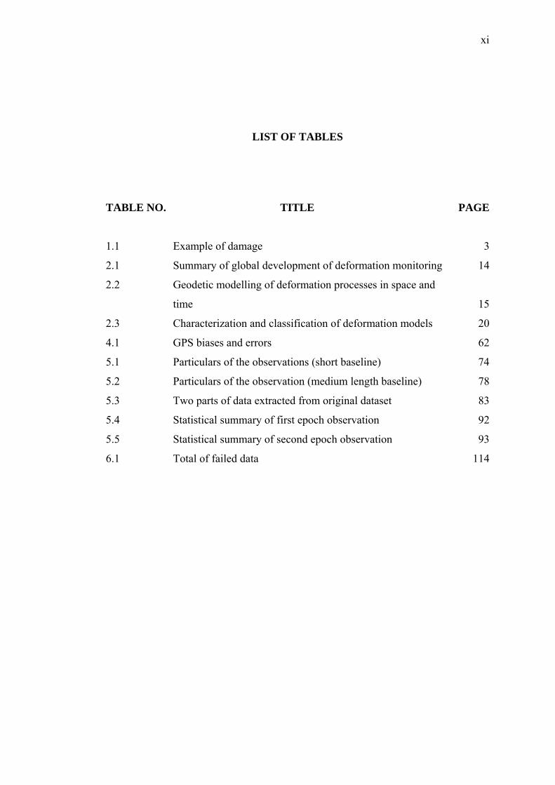
LIST OF TABLES
TABLE NO. TITLE PAGE
1.1 Example of damage 3
2.1 Summary of global development of deformation monitoring 14
2.2 Geodetic modelling of deformation processes in space and
time 15
2.3 Characterization and classification of deformation models 20
4.1 GPS biases and errors 62
5.1 Particulars of the observations (short baseline) 74
5.2 Particulars of the observation (medium length baseline) 78
5.3 Two parts of data extracted from original dataset 83
5.4 Statistical summary of first epoch observation 92
5.5 Statistical summary of second epoch observation 93
6.1 Total of failed data 114

xii
LIST OF FIGURES
FIGURE NO. TITLE PAGE
1.1 Main focus of the research scope 5
1.2 Research methodology 8
2.1 Deformation as an element of a dynamic system 16
2.2 Hierarchy of models in geodetic deformation analysis 18
2.3 Method of system identification 20
2.4 Advancement of monitoring scheme 24
3.1 The basic concept of satellite point positioning system 35
3.2 Intersection of three ranges with radii 36
3.3 The basic concept of relative satellite positioning 37
3.4 Pseudo-range measurement 41
3.5 Carrier beat phase measurement 45
3.6 “Family tree” of GPS positioning 47
3.7 Concept of pseudo-ranging 48
3.8 Absolute kinematic positioning 54
3.9 Relative kinematic positioning 54
4.1 Satellite distributions of good and poor GDOPs 59
4.2 Cycle slips 68
4.3 Direct signal and multipath signal 70
5.1 Reference station at UTM observatory (left) and rover
station at UTM hockey field (right) 75
5.2 (a) Time series of northing of first epoch (March 16, 2006) 75
5.2 (b) Time series of easting of first epoch (March 16, 2006) 76
5.2 (c) Time series of elevation of first epoch (March 16, 2006) 76
5.3 (a) Time series of northing of second epoch (April 11, 2006) 77
5.3 (b) Time series of easting of second epoch (April 11, 2006) 77

xiii
5.3 (c) Time series of elevation of second epoch (April 11, 2006) 78
5.4 Reference station BANT (Banting) at Sek. Men. Keb. Sg.
Manggis (left); Rover station UPMS (UPM Serdang) at Jab.
Kej. Biologi & Pertanian (right) 79
5.5 (a) Time series of elevation, MyRTKNet, 13:59:47 – 19:59:46,
August 6, 2006 80
5.5 (b) Time series of elevation, MyRTKNet, 19:59:47, August 6,
2006 – 01:59:46, August 7, 2006 81
5.6 Time series of elevation, MyRTKNet, 01:59:47 – 07:59:46,
August 8, 2006 81
5.7 (a) Time series of northing, MyRTKNet, 01:59:47 – 07:59:46,
August 7, 2006 82
5.7 (b) Time series of northing variation, MyRTKNet, 01:59:47 –
07:59:46, August 7, 2006 83
5.8 (a) Time series of northing normal point of first epoch
observation 86
5.8 (b) Time series of easting normal point of first epoch
observation 86
5.8 (c) Time series of elevation normal point of first epoch
observation 87
5.9 Reference station is disturbed 88
5.10 Sample layout of field component distribution 89
5.11 (a) Time series of northing (integrated) 90
5.11 (b) Time series of easting (integrated) 91
5.11 (c) Time series of elevation (integrated) 91
6.1 Fundamental of Sparrow 96
6.2 Structure of Sparrow 101
6.3 Workflow of Conveyor 103
6.4 Screenshot of main window of Conveyor 104
6.5 Screenshot of main window of Compiler 105
6.6 Sample layout of the components at the field 107
6.7 Real-time result presentation in graph form 109
6.8 Example of the distribution of field components in the larger
area 110

xiv
6.9 (a) Results of first test – N 111
6.9 (b) Results of first test – E 112
6.10 (a) Results of second test – N 112
6.10 (b) Results of second test – E 113
6.11 (a) Results of third test – N 113
6.11 (b) Results of third test – E 114

xv
LIST OF ABBREVIATIONS
ASNT American Society for Nondestructive Testing
C/A-code Coarse/Acquisition Code
CC Control Centre
CRS Core Reference Station
CSP Control Station Processing
CW Continuous Wave
DoD United States Department of Defence
DOP Dilution of Precision
FBG Fiber Bragg Grating
FDD Frequency Domain Decomposition
FEM Finite Element Method / Modelling
FFT Fast Fourier Transformation
FIG International Federation of Surveyors
GGA GPS fix information
GPS Global Positioning System
GT Global Threshold
LAN Local Area Network
LSE Least Squares Estimation
NP Normal Point
InSAR Interferometric Synthetic Aperture Radar
IWST Iterative Similarity Weighted Transformation
JUPEM Department of Survey and Mapping, Malaysia
LT Local Threshold
LGT Lower Global Threshold
LLT Lower Local Threshold
MIMO Multiple Input - Multiple Output
MINT Malaysian Institute for Nuclear Technology Research

xvi
NAVSTAR Navigation Satellite Time and Ranging
NDT Non-Destructive Testing
NMEA National Marine Electronics Association 0183 Standard
NP Normal Point
OP Original Point
OTF On-the-Fly
P-code Precision code
PRN Pseudo-Random Noise
PRC Pseudo-Range Correction
RF Radio Frequency
RRS Reserved Reference Station
RTK Real-Time Kinematic
SHM Structural Health Monitoring
SPS Standard Position Service
TCP/IP Transmission Control Protocol / Internet Protocol
TGO Trimble Geomatics Office
TPS Terrestrial Positioning System
TRS Trimble Reference Station
TSIP Trimble Standard Interface Protocol
UERE User Equivalent Range Error
UHF Ultra High Frequency
UGT Upper Global Threshold
ULT Upper Local Threshold
UM Usage Monitoring
UTC Universal Time Coordinated
USACE United State Army Corps of Engineers
VBA Visual Basic for Applications
VHF Very High Frequency
VNC Virtual Network Computing
WG 6.1 Working Group 6.1 on Deformation Measurements and Analysis
WGS84 World Geodetic System 1984

xvii
LIST OF SYMBOLS
no - Fundamental natural frequency or period of a building
D - Base direction (in meters) in the direction of motion considered of the
building
H - Height of the building (in meters)
C - Centre of mass of the earth
R - Position vector of the antenna to seek
r - Known position vector of satellite
ρ - True range from transmission at satellite to reception at receiver or
antenna
y - Propagation of electromagnetic wave from the satellite to the receiver
A - Signal amplitude
k - Propagation wavenumber related to the free space wavelength
t - Elapsed time measured from the instant of transmission at the satellite
x - Distance travelled of the electronic wave from the satellite to the
receiver
ω - Radian frequency
φ - Bias term
fo - Fundamental frequency of GPS signal
p - Measured pseudo-range
c - Velocity of light
dt - Offset of the satellite clock from GPS time
dT - Offset of the receiver clock from GPS time
dion - Ionospheric delay
dtrop - Tropospheric delay
Φ - Measured carrier phase in length units
N - Unknown cycle count

xviii
λ - Wavelength
σo - Measurement accuracy
σ - Positioning accuracy
RE - Range error due to clock instability / timing biases
TO - Time offset
DC - Dry term range contribution in zenith direction in meters
PO - Surface pressure in millibar (mb)
TL - Local tolerance
TG - Global tolerance
N - Meridian arc distance from reference station (of user-defined
coordinate system used in Sparrow)
E - Arc distance along the parallel latitude from reference station (of user-
defined coordinate system used in Sparrow)
h - Ellipsoidal height of antenna (of user-defined coordinate system used
in Sparrow)
φ - Latitude of geodetic coordinate system
λ - Longitude of geodetic coordinate system
H - Antenna altitude of geodetic coordinate system
Ngeoid - Geoidal separation
Sφ - Meridian arc distance
Sλ - Arc distance along the parallel latitude
RM - Radius of curvature in meridian
RN - Radius of curvature in the prime vertical

xix
LIST OF APPENDICES
APPENDIX TITLE PAGE
A Street, Drainage and Building Act 1974 (Act 133) 126
B Enhancements of Data Processing, Algorithms or Software 129
C Time Series of Sampled Forty-Eight-Hour Continuous
MyRTKNet Data 135
D National Marine Electronics Association 0183 Standard 147
E Coordinate Conversion 149
F Field Procedure and Testing of Sparrow 153

CHAPTER 1
INTRODUCTION
1.1 Background
Numerous accidents or disasters associated with large construction projects
and natural events in the past have cost not only the great loss financially but also the
lives that eternally embedded the great pain in the memory of their beloved family
and friends. These horrendous tragedies include
(i) Sultan Abdul Halim Ferry Terminal Bridge collapse (July 31, 1988),
(ii) Highland Towers Condominium collapse (December 11, 1993),
(iii) Tsunami induced by the Indian Ocean earthquake (December 24,
2004), and
(iv) many other landslides, tremors as well as sudden collapse of the floor
of a building during construction.
Further information on the abovementioned tragedies can be acquired at Wikipedia,
(the free encyclopedia) and the study, entitled Non-Destructive Testing of Concrete
and Civil engineering Structures, carried out by Malaysian Institute for Nuclear
Technology Research (MINT). Besides, questions on whether our buildings are able
to withstand the tremors have also been raised by the recent aftershocks caused by
the earthquakes that struck the region. Further information on the discussion of the
aftershocks can be reached at Property Times, the New Straits Times (2006).
These tragedies and aftershocks have awakened the public awareness and
concern of the structure safety as well as natural event. Also, the need of monitoring
has been called to serve as the alarm system or early-warning system. According to

2
aforementioned study carried out by MINT, it was reported that amendment had been
made to Street, Drainage and Building Act 1974 (Act 133) as a follow up of the
Highland Towers tragedy. The act requires that after every ten years all high-rise
building of more than five floors must be inspected for their safety before the
renewal of certificate of fitness can be made. The Section 85A of the act is attached in
Appendix A.
In usual practices, the non-destructive testing (NDT) or structural health
monitoring (SHM) will be implemented to assess the damage in structure and
examine the integrity of the structure in order to come to a conclusion of the useful
life or serviceability of the structure. In general, NDT and SHM hold a same role
which is to ultimately guarantee the safety of the public. A brief introduction on
NDT as well as SHM and damage is given in the following.
The American Society for Nondestructive Testing (ASNT) define the NDT as
comprising those test methods used to examine an object, material or system without
impairing its future usefulness. The term is generally applied to nonmedical
investigations of material integrity. Non-destructive testing is concerned in a
practical way with the performance of the test piece, such as, how long may the piece
be used and when does it need to be checked again. The British Institute of Non-
Destructive Testing define the NDT as the branch of engineering concerned with all
methods of detecting and evaluating flaws in materials of that the flaws can affect the
serviceability of the material and structure.
Based on A Review of Structural Health Monitoring Literature: 1996-2001,
SHM is defined as the process of implementing a damage detection strategy for
aerospace, civil, and mechanical engineering infrastructure. Usage monitoring (UM)
attempts to measure the inputs to and responses of a structure before damage so that
regression analysis can be used to predict the onset of damage and deterioration in
structural condition (further discussion on the inputs to and responses of structure is
continued in Section 2.3.2. Prognosis is the coupling of information from SHM, UM,
current environmental and operational conditions, previous component and system
level testing, and numerical modelling to estimate the remaining useful life of the
system (Sohn et al., 2003). Also, according to Summary Report on the first

3
International Workshop on Structural Health Monitoring, the essence of SHM
technology is to develop autonomous built-in systems for the continuous real-time
monitoring, inspection, and damage detection of structures with minimum labour
involvement (Harb, 2005).
In the most general terms, damage can be defined as changes introduced into
a system that adversely affects its current or future performance. Implicit in this
definition is the concept that damage is not meaningful without a comparison
between two different states of the system, one of which is assumed to represent the
initial, and often undamaged, state. On the study of damage identification in
structural and mechanical systems, the definition of damage therefore will be limited
to changes to the material and / or geometric properties of these systems, including
changes to the boundary conditions and system connectivity, which adversely affect
the current or future performance of these systems (Sohn et al., 2003). Some of the
examples of damage are shown in the Table 1.1 below.
Table 1.1: Example of damage.
Damage Change
Crack Stiffness change
Scour Boundary condition change
Weight loss Mass change
Joint loosening Connectivity change
However, to have the comprehensive diagnosis of the structure health or
prognosis of damage in detail, there are a number of different measurements that
have to be made for instance (but are not limited to) strain, acceleration, temperature,
transmission and displacement. Further classification on the measurement is
discussed in Section 2.3.2 (Ad-Hoc Committee of FIG, 2001; Sohn et al., 2003).
Nevertheless, the displacement measurement is the main concern of this thesis.
Basically, the displacement could be arrived at by two main approaches,
namely geotechnical approach and geodetic approach. Geotechnical approach uses
the special devices such as strain gauges, piezometers, tiltmeters, extensometers and

4
many others to obtain the required type of displacements. However, the geodetic
approach uses the surveying positioning techniques to derive the displacement.
Either geotechnical or geodetic approach, they can be employed to measure / monitor
the displacement of the man-made structure (e.g. dam, high-rise building, bridge,
tunnel, etc.) and natural features (e.g. slope and the areas encountering with landslide,
subsidence, liquefaction, uneven settlement, mass movement, etc.).
The thesis focuses on the geodetic approach. The main difference of the
geodetic approach is that it uses the surveying technique to provide the feedback of
the response of the monitored object in term of position, which is, in turn, used to
derive the displacement (magnitude and direction) as well as displacement speed
(velocity). The derived displacement can be then described as deflection, settlement,
drift and others. For this reason, displacement measurement is also comparable to
deformation measurement.
Besides, in geodetic approach, there is also a number of positioning
techniques that can be used to perform the displacement measurement, such as
conventional terrestrial based method (by using theodolite or total station), global
positioning system (GPS) and photogrametry (by using camera or scanner). However,
GPS is the positioning technique to be looked into in this research.
Moreover, regardless to the positioning mode (absolute positioning or relative
positioning), GPS positioning technique can be further divided into two different
technique, namely, static positioning and kinematic positioning. Yet, the research
focuses on the kinematic positioning with real-time solution or in short real-time
kinematic (RTK) positioning technique.
Summing up all the comments abovementioned, in short, the main focus of
the research scope is shown in the “reserve pyramid” in Figure 1.1.

5
Non-Destructive Testing / Structural Health Monitoring
Displacement / deformation measurement
Geodetic approach
GPS positioning
RTK positioning technique
Figure 1.1: Main focus of the research scope.
Before continuing the discussion, some statements on the terms used in the
thesis are advisable. Throughout the thesis, displacement and deformation are
comparable. However, deformation measurement and deformation monitoring are
not quite comparable. Deformation measurement is used to represent the quantitative
measurement, whereas, deformation monitoring is used to represent the practice in
the real scenario, inclusive of both deformation measurement and analysis.
1.2 Problem Statements
Back in the late of 1970s, the GPS technology was introduced when the first
launch of the GPS satellite on February 22, 1978 (Leick, 2004). Since then, many
industries have been benefited from the technology of GPS. Surveying industry has
been no different. Researches have been (and are still) carried out and benefits have
been (and are still) brought in. However, due to the expensive equipments (as
compared to the conventional terrestrial surveying equipments), GPS technology is
still fresh in Malaysian surveying industry. Only the education institutions and
government departments have the regular practices. Furthermore, Malaysia, the
country that has been gifted the advantageous geographical and geological location
(e.g. free from earthquake and volcano), have no intensive practices in monitoring

6
(structures as well as natural events). This also results the lack of proper reference or
standard guideline for using GPS in deformation monitoring. Nevertheless, as it has
been discussed in Section 1.1, there are, in truth, the needs of deformation
monitoring in Malaysia.
Today RTK positioning technique is certainly one of the most valuable assets
of GPS. Although many researches have suggest and proven the feasibility of using
RTK positioning (examples are given in Section 2.5) in deformation monitoring,
directly employing the manufacturers’ RTK positioning solution (the output obtained
from the receiver) in deformation monitoring is doubtful. In other words, the possible
errors (e.g. multipath and cycle slips) and reference station reliability that deteriorate
the quality of RTK positioning are the main concern.
Besides, the main essence of RTK positioning is its advantage to provide the
direct measurement of relative displacement and real-time measurement (online and
offline application). Nevertheless, until latest, there is still very lack off-the-shelf
online RTK positioning application, while offline RTK positioning solution does not
offer the real time (on the spot) deformation monitoring. Real time deformation
detection plays the prominent role in guaranteeing public safety.
Furthermore, automated and continuous monitoring is also the latest and in
demand monitoring. This is because automated and continuous monitoring greatly
levels the efficiency of deformation monitoring, such as, saving the manpower,
reducing human gross error and handling the round-the-clock monitoring. However,
the smart and handy applications have to be self developed or customized.
A reliable RTK positioning technique for deformation monitoring and a
computer-aided approach to perform the online, automated and continuous
deformation monitoring are the concern of the thesis.

7
1.3 Research Objectives
Based on the problem statements discussed in the previous section, the
research objectives are as follows.
(i) To investigate RTK positioning integrity monitoring and deformation
detection method to improve the direct employment of manufacturer’s
RTK positioning technique for deformation monitoring system.
(ii) To enhance the employment of RTK positioning technique in
deformation monitoring, particularly in online, automated and
continuous deformation monitoring by developing prototype software.
1.4 Research Contributions
Parallel to the research objectives, the research has two significances as
follows.
(i) An additional method for RTK positioning integrity monitoring
(inclusive of RTK output quality and reference station stability) and
deformation detection is proposed.
(ii) A prototype deformation monitoring system for automated, online and
continuous monitoring scheme is developed. The prototype can be
reference for structure deformation and landslide study that concerns
the public safety in Malaysia.
The main difference between the research and other glorious and famous
researches is that the research looks into an additional method for manufacturers’
RTK positioning solution which concerns the RTK integrity monitoring and
deformation detection so that it can be employed directly for online, automated and
continuous deformation monitoring. Algorithm development for processing raw GPS
data to obtain the RTK solution for deformation monitoring is not in the scope of the
research, yet, it is recommended for future work.

8
1.5 Research Methodology
The process of the whole research is summarised as shown in the flow chart
in Figure 1.2.
Figure 1.2: Research methodology.
Literature review:
To look for the appropriate scope of research that is relevant and significant to local needs.
Data sampling and analysis:
To collect sample data so as to i) look into the aptitude of RTK positioning, ii) to propose the proper method for deformation
monitoring (inclusive of RTK data monitoring), and
iii) verify the appropriateness of using the RTK positioning technique in deformation monitoring.
Prototype software development:
To develop prototype software based on the findings of the research and to serve the purposes of automated, online and continuous deformation monitoring.
Simulation test:
To justify the findings of the research and test the technical feasibility of the developed prototype software.
Start
Conclusion and recommendations:
To conclude the research and to give the recommendations to the future works.
End

9
1.6 Outline of the Thesis
The thesis consists of seven chapters and six appendixes.
Chapter 1 gives the introduction to the research by delivering the background
Chapter 2 peruses the development of deformation monitoring (global
Chapter 3 discusses the fundamental of GPS positioning as well as RTK
Chapter 4 discusses the GPS accuracies, error and bias sources, and
gmen
Chapter 5 presents the results of sampled data, and proposes an additional
ethod
Chapter 6 describes the developed prototype software, Sparrow. The
of the research, problem statements, research objectives, research contributions,
research methodology as well as structure of the thesis.
development of deformation monitoring, classification of deformation models and
terminology, and classification of monitoring schemes) and the employment of GPS
in deformation monitoring (scientific justification and technical feasibility,
competency of RTK positioning in deformation monitoring, and state-of-the-art
deformation monitoring system).
positioning technique. The chapter begins the discussion from the basic of satellite
positioning until the scope of RTK positioning, that include GPS signal structure,
GPS ranging, and GPS positioning mode, absolute positioning, relative positioning,
and kinematic positioning.
au tation options so that they can be referenced in the following chapters.
m for RTK positioning integrity monitoring (error identification, outlier
filtering and reference station stability checking) and deformation detection.
description includes the Sparrow briefing, software design, software structure and
software functionalities. Besides, three tests to verify the applicability of Sparrow
and validity of Normal Point (NP) are included.

10
Chapter 7 gives the concluding remarks of the research as well as the
Appendix A attaches the Section 85A from the Street, Drainage and Building
Appendix B attaches four examples of enhancements of data processing,
Appendix C presents the results of sampled forty-eight-hour continuous
Appendix D elucidates the National Marine Electronics Association (NMEA)
Appendix E discusses the conversion from geodetic coordinate system to the
Appendix F describes the field procedure of using Sparrow as well as process
recommendations to the future works.
Act 1974 (Act 133).
algorithms or software.
RTKNet data.
0183 Standard.
user-defined coordinate system used in the research.
and result of the tests for the developed prototype software.