computer aided design of useful spherical watt i six-bar linkages
TRANSCRIPT

COMPUTER AIDED DESIGN OF USEFUL SPHERICAL WATT I SIX-BAR LINKAGES
Kaustubh H. SonawaleRobotics and Automation Laboratory
University of CaliforniaIrvine, California 92697
Email: [email protected]
Alex ArredondoRobotics and Automation Laboratory
University of CaliforniaIrvine, California 92697
Email: [email protected]
J. Michael McCarthy∗Robotics and Automation Laboratory
University of CaliforniaIrvine, California 92697
Email: [email protected]
ABSTRACTThis paper presents a software system for the kinematic syn-
thesis of useful spherical Watt I six-bar linkages that can guidea body through five task positions. The design procedure beginswith the specification of a spherical 3R open chain that reachesfive specified task positions. The six-bar linkage is designed byconstraining the 3R spherical chain to the topology of a Watt Ispherical six-bar linkage. The CAD software SolidWorks is usedto specify the 3R chain and the five spherical task positions. Wedescribe the SolidWorks Add-In MechGen that reads the Solid-Works data and generates candidate linkages. Included in thetask specification are tolerance zones that allow random adjust-ments to the task positions to search for defect-free linkages. Anexample is provided that demonstrates the five position synthesisof a useful spherical Watt I six-bar linkage.
INTRODUCTIONIn this paper, a computer aided design system for the syn-
thesis of spherical Watt I six-bar linkages is presented. The pro-cedure verifies that the generated linkage is defect-free, whichwe term useful. This paper implements the synthesis proceduredescribed by Soh and McCarthy [1], which designs a spheri-cal six-bar linkage by computing constraints to a 3R sphericalchain. The calculation of these constraints uses Burmester the-ory for spherical linkages described by Chiang [2]. In addition,this synthesis procedure implements search procedure introducedby Plecnik and McCarthy [3] that finds useful linkages for tasks
∗Address all correspondence to this author.
within a tolerance zone around the given task positions.Our design procedure for a spherical Watt I six-bar link-
age is implemented in a computer aided design system that in-tegrates a Mathematica synthesis algorithm into the geometricmodeling software SolidWorks as an Add-in using Visual Basiccalled MechGen. The organization of this computer-aided designsystem is demonstrated by an example synthesis of a sphericalsix-bar linkage.
LITERATURE SURVEYThe computer aided design of linkages that combines
Burmester theory with interactive graphics originated with Kauf-man [4, 5] who developed a system for the synthesis of planarfour-bar linkages that guide a moving frame through a set of taskpositions. Also see Erdman [6, 7] and Waldron [8]. Ruth andMcCarthy [9] extended this work to the design of spherical four-bar linkages, and Larochelle and colleagues [10,11] used VirtualReality for the synthesis of both spherical and spatial four-barlinkages. Alvarez and Su [15] have extended this use of VirtualReality to the conceptual design of linkages.
Alizade [12, 13] has developed a design methodology forspherical four-bar function generators. Hernandez et al. [14]have formulated the design of a spherical Stephenson six-barlinkage and Soh and McCarthy [1] use Burmester theory todesign spherical six-bar linkages as constrained 3R sphericalchains. This paper describes design system MechGen whichis the first computer-aided design system that uses interactivegraphics for the synthesis of useful spherical Watt I six-bar link-
Proceedings of the ASME 2013 International Design Engineering Technical Conferences and Computers and Information in Engineering Conference
IDETC/CIE 2013 August 4-7, 2013, Portland, Oregon, USA
DETC2013-13454
1 Copyright © 2013 by ASME
Downloaded From: http://proceedings.asmedigitalcollection.asme.org/ on 05/18/2014 Terms of Use: http://asme.org/terms

O
A B
C
E
F
D
Tool Frame
0 1 2 3
4 5
First Four-bar
Second Four-bar
2
First RRConstraint
Second RRConstraint
3R Chain
1
η
B1
B2
B3
FIGURE 1. LINKAGE GRAPH AND SCHEMATIC OF A SPHER-ICAL WATT I SIX-BAR LINKAGE
ages.
SYNTHESIS THEORYOur synthesis procedure for the spherical Watt I six-bar link-
age begins with the specification of a spherical 3R chain and aset of five task positions. The spherical six-bar is obtained by de-signing RR links that constraint the 3R chain to the Watt 1 topol-ogy, Fig.1. This synthesis procedure is described in McCarthyand Soh [16], and we summarize it here.
The task for the synthesis of the spherical Watt I six-bar link-age is prescribed by five task orientations which are described bythe 3x3 rotation matrices, [Tj], j = 1, . . . ,5, that define the ori-entation of the moving frame M relative to the ground frame F .In addition, the design specifies a 3R spherical chain defined byjoint axes O, A and D, see Fig.1. Three link frames denotedas B1, B2 and B3 are attached to the three links of the 3R chain
such that they have their origins at O, A and D respectively, withtheir z-axes directed along the joint (radially outwards) and theiry-axes perpendicular to the plane of the link as shown in Fig.1.
Inverse kinematics of the 3R chainLet [G] denote the transformation matrix that maps the base
of the 3R chain to the fixed frame F and let [H] map the toolframe in the last link of the 3R chain. Then the kinematics equa-tion for the 3R chain is given by
[K(θ1,θ2,θ3)] = [G][B1(θ1)][B2(θ2)][B3(θ3)][H], (1)
where θi, i = 1,2,3 are the joint rotations.With the knowledge of the kinematics equation
[K(θ1,θ2,θ3)] for each of the five spherical 3R chains forthe five task orientations [Tj], j = 1, . . . ,5, we can now use theinverse kinematics to compute the angles θi, j such that,
[Tj] = [K(θ1 j,θ2 j,θ3 j)], j = 1, . . . ,5. (2)
Synthesis of the first RR constraintThe joint values θi, j allow us to compute the orientation of
the link frame B2 relative to the ground frame in the five taskorientations, that is
[C j] = [G][B1(θ1 j)][B2(θ2 j)], j = 1, . . . ,5. (3)
This yields the rotations relative to the first task orientation, as
[R1 j] =([G][B1(θ1 j)][B2(θ2 j)])([G][B1(θ11)][B2(θ21)])T
j = 1, . . . ,5. (4)
The five relative orientations [R1 j] of the link AD are nowused to design the RR chain CB. The requirement that B main-tain a constant angle ρ1 relative to C in the five orientations yieldsthe five design equations
([R1 j]B) ·C = |B||C|cosρ1, j = 1, . . . ,5. (5)
These equations can be solved numerically to yield as many sixsets of coordinates for the link CB, refer Chiang and McCarthy[2] [16].
Analyze the four-bar chainThe joint A of the original 3R chain and the new joint B
are part of the same link, therefore their coordinates satisfy the
2 Copyright © 2013 by ASME
Downloaded From: http://proceedings.asmedigitalcollection.asme.org/ on 05/18/2014 Terms of Use: http://asme.org/terms

constraint equation
A ·B = |A||B|cosη , (6)
where η is the angle between the joint axes A and B, refer Fig.1.Expanding this constraint equation in terms of the input angle θ1and the angle ψ at C, we obtain an equation of the form
A(θ1)cosψ +B(θ1)sinψ =C(θ1), (7)
where the A(θ1), B(θ1) and C(θ1), are defined in terms of thedimensions of the spherical chain OABC refer McCarthy [16].
The solution of Eqn. (7) for each of the values θ1 j, yields theangles ψ j, j = 1, . . . ,5. The orientation of the link CB in each ofthe task orientations is given by
[D j] = [GC][B4(ψ j)], j = 1, . . . ,5, (8)
where [GC] is the transformation from the base frame F to thejoint C and [B4(ψ j)] is the rotation about C.
Synthesis of the second RR constraintWe now use the known orientations of link B3 of the 3R
chain and the link CB to design a second RR constraint FE.From the inverse kinematics of the 3R chain, we can computethe relative positions [R1 j] of the end-link,
[R̄1 j] = ([G][B1(θ1 j)][B2(θ2 j)][B3(θ3 j])
× ([G][B1(θ11)][B2(θ21)[B3(θ3 j])T
j = 1, . . . ,5. (9)
Similarly, we can compute the relative positions of link CB,
[S1 j] = ([GC][B4(ψ j)])([GC][B4(ψ1)])T , j = 1, . . . ,5. (10)
The second RR chain constrains a joint E in the end-linkto maintain a constant angle relative to the joint F in the linkCB, in each of the task orientations. This yields the five designequations,
([R̄1 j]E) · ([S1 j]F) = |B||C|cosρ2, j = 1, . . . ,5. (11)
These equations can be solved to obtain as many as six sets ofvalues for the coordinates of the joints E and F. The result is aset of spherical Watt I six-bar linkages that guide an end-effectorthrough five task orientations, see McCarthy [16].
EVALUATION OF GENERATED LINKAGESThe candidate linkages generated from the synthesis pro-
cess may suffer from circuit and branch defects, as describedby Chase et al. [17]. In order to filter these linkages for defects,MechGen uses the direct kinematics equation Eqn. (7) to analyzeeach of the two spherical four-bar linkages using the theory pre-sented in McCarthy [16]. Solving this equation yields two valuesfor the output crank angle for a given input crank angle as shownin the Eqn. (12) below. The two angles result from the fact thecoupler link and the output crank can be assembled in two con-figurations namely elbow up and elbow down for the same inputcrank angle, which corresponds to the plus and minus values inthe equation,
ψ(θ) = arctan(
BA
)± arccos
(C√
A2 +B2
). (12)
.This equation also gives us a formula to find the bounds on
the range of the input crank angle, through the argument of thearccos term, which is subjected to the bounds −1 and +1. Ifthis is not satisfied then the linkage cannot be assembled for thespecified input crank angle. MechGen uses this Eqn. (12) to filterboth the first four-bars and second four-bars. The two checksused to filter defective linkages are:
1. The orientation of the output crank with respect to the cou-pler that is the elbow up or elbow down configurationThe elbow of the output crank with respect to the couplershould be either up or down for all the five task positions.This avoids circuit change when the input crank is a crank(range 0 to 2π), branch change when it is a 0-rocker or π-rocker or just rocker, see McCarthy [16].
2. The limits on the input crankThe 5 crank angles for the five task positions should lie in therange bounded by the two values obtained from the arccosargument in Eqn. (12). This defect occurs in the case, whenthe input crank is a rocker. The linkage might have elbow upor down configuration same for all the task positions, that isall configurations may seem to lie on the same branch butthey might be on different circuits. So this check preventscircuit change when input crank is rocker.
These two checks are sufficient to take care of circuit orbranch defects and the resulting spherical Watt I six-bar linkagesare usable linkages.
OUTLINE OF THE LINKAGE DESIGN ALGORITHMThe flowchart for linkage design algorithm is shown in
Fig. 2. The input for the linkage design algorithm consists ofthe five task positions (orientations) of the moving body with re-spect to the fixed body, the spherical serial 3R chain data that
3 Copyright © 2013 by ASME
Downloaded From: http://proceedings.asmedigitalcollection.asme.org/ on 05/18/2014 Terms of Use: http://asme.org/terms

guides the end effector through the five task positions, and thenumber of iterations and tolerances.
Using the task positions and 3R chain data, the algorithmfirst synthesizes all the possible first four-bar OABC candidates,refer Fig.1, and then analyzes them for defects. If the algorithmdoes not find a single useful linkage, it breaks the control se-quence, randomizes the task positions within the tolerance rangeand starts the process again. If some useful linkages are found,then the algorithm pushes them to the next step of synthesizingthe second four-bars BDEF, for each these first four-bars. Af-ter analyzing each of the second four-bar, if the algorithm againdoes not find a useful linkage, it breaks control sequence, ran-domizes the task positions within the tolerance range and startsthe process again. If some useful linkages are found, then thespherical Watt I six-bar linkage as a whole is saved. This processrepeats itself till the counter increments to the number of itera-tions. Following that, the saved useful spherical Watt I six-barlinkages are ranked on a criteria, which is the ratio of length ofthe longest link to the length of the shortest link, as described bySoh [18].
MECHGEN DESIGN PROCESSThe paper uses the car door opening example for explaining
the design process.Step 1: Motion Requirement
The user’s requirement for the motion of the car door with re-spect to the car body as five orientations is shown in Fig.3. SinceMechGen can do only five position synthesis, the motion require-ment has to be discretized into five door positions.
Step 2: Specifying five Task PositionsDue to the inherent complexity in specifying the spherical taskpositions (orientations), MechGen has a part file embedded in it,which is referred to as the Environment. This part file has twosketches built in; one for the five task positions and one for the3R serial chain. In this step MechGen software is opened andEnvironment part file is imported in the working assembly asshown in Fig.6. The user edits the sketch for task positions toget a movement that is close to the requirement. Five doors areattached to the task positions to confirm this as shown in Fig.4.
Step 3: Specifying the five 3R chainsIn this step the user edits the 3R chain sketch in the Environmentfile to specify the backbone serial chain as shown in Fig.5.
Step 4: Import the task postion and 3R chain informationin MechGenIn this step the user selects the 3R chain sketch in Environmentand clicks on the ”Import From SolidWorks” button. MechGencaptures all the information and displays it to the user, along withseveral verification checks to display errors if any, as shown inFig.7.
Step 5: Generate linkage solutionsIn this step the user specifies the number of iterations and the
Randomizebtaskbpositionsincrementbcounter
Read5btaskbpositions3Rbchainbdata
#bofbiterationsbandbtolerancesinitializebcounterb=b1
Sortbthebsavedblinkagebsolutions
End
Start
SynthesisbandbEvaluationbofbFirstbFour-barb
Isbtheblinkagebusefulb?
YES
NO
SynthesisbandbEvaluationbofbSecondbFour-barb
Isbtheblinkagebusefulb?
YES
NO
AnimatebthebentireblinkageSaveblinkagebsolution
counterb<bYbofbiterationsb
YES
NO
FIGURE 2. DESCRIPTION OF THE SPHERICAL WATT I SIX-BAR LINKAGE SYNTHESIS ALGORITHM IN MECHGEN.
tolerances and then clicks on the ”Generate Linkages” buttonto generate solutions. The generated solutions are displayed asshown in Fig.8. The user can select a linkage from the solu-tion box and generate its SolidWorks assembly by clicking onthe ”Start” button. Figure 9 show four example linkages gener-
4 Copyright © 2013 by ASME
Downloaded From: http://proceedings.asmedigitalcollection.asme.org/ on 05/18/2014 Terms of Use: http://asme.org/terms

FIGURE 3. THE DESIGN TASK IS SPECIFIED AS A SET OF ORI-ENTATIONS OF THE CAR DOOR RELATIVE TO THE CAR BODY
FIGURE 4. THE TASK ORIENTATIONS READ BY MECHGEN.
ated by MechGen in SolidWorks.Step 6: Integrating desired linkage in user assembly
In this step the user imports the desired linkage solution in tothe car assembly and integrates it. Figure 10 shows the fi-nal car door assembly along with the spherical Watt I six-barlinkage that guides the door through the five task positions.A video of this linkage in action can be found on http://mechanicaldesign101.com.
Generating Solid Geometries in SolidWorksThe development of this module in MechGen began with
recording macros of simple shapes drawn in the SolidWorks userinterface. When saved, these macros provided the Visual Ba-sic commands, parameters and code sequence required to pro-duce these simple shapes. Various macros were then altered andcombined into a simple Visual Basic (VB6) program. With fur-ther development, MechGen became capable of producing Solid-Works assembly for the planar six-bar linkage using primitiveshapes. To take advantage of the .NET Framework, the develop-ment of the software was later shifted the to VB.NET.
FIGURE 5. 3R SPHERICAL CHAIN READ BY MECHGEN
FIGURE 6. SPECIFY NO. OF INTERATIONS AND TOLERANCEZONES IN MECHGEN
During the linkage generation process, MechGen creates aseparate part file for each spherical link. A link is created usinglines and arcs to form a closed loop and then extruded to give ita three dimensional structure. Once all the part documents arecreated, an assembly document is made and the parts are im-ported into the assembly model space. The software then selectsthe origin of a link in a part document and mates it to the ori-gin of the assembly document. The process is repeated until allthe part document origins are coincident with the assembly docu-ment origin. Next, the software applies a collinear mate betweenthe joint axis of the connecting links. Each link is connected inthis manner until all joint axes are constrained. This completesthe assembly for the spherical Watt I six-bar linkage and rotatingthe input link will cause the end-effector to move through the fivetask positions.
5 Copyright © 2013 by ASME
Downloaded From: http://proceedings.asmedigitalcollection.asme.org/ on 05/18/2014 Terms of Use: http://asme.org/terms
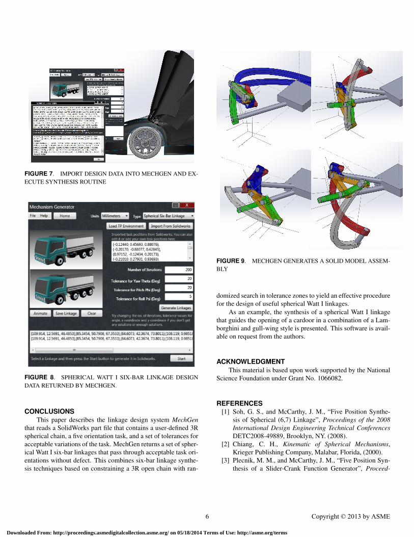
FIGURE 7. IMPORT DESIGN DATA INTO MECHGEN AND EX-ECUTE SYNTHESIS ROUTINE
FIGURE 8. SPHERICAL WATT I SIX-BAR LINKAGE DESIGNDATA RETURNED BY MECHGEN.
CONCLUSIONSThis paper describes the linkage design system MechGen
that reads a SolidWorks part file that contains a user-defined 3Rspherical chain, a five orientation task, and a set of tolerances foracceptable variations of the task. MechGen returns a set of spher-ical Watt I six-bar linkages that pass through acceptable task ori-entations without defect. This combines six-bar linkage synthe-sis techniques based on constraining a 3R open chain with ran-
FIGURE 9. MECHGEN GENERATES A SOLID MODEL ASSEM-BLY
domized search in tolerance zones to yield an effective procedurefor the design of useful spherical Watt I linkages.
As an example, the synthesis of a spherical Watt I linkagethat guides the opening of a cardoor in a combination of a Lam-borghini and gull-wing style is presented. This software is avail-able on request from the authors.
ACKNOWLEDGMENTThis material is based upon work supported by the National
Science Foundation under Grant No. 1066082.
REFERENCES[1] Soh, G. S., and McCarthy, J. M., “Five Position Synthe-
sis of Spherical (6,7) Linkage”, Proceedings of the 2008International Design Engineering Technical ConferencesDETC2008-49889, Brooklyn, NY. (2008).
[2] Chiang, C. H., Kinematic of Spherical Mechanisms,Krieger Publishing Company, Malabar, Florida, (2000).
[3] Plecnik, M. M., and McCarthy, J. M., “Five Position Syn-thesis of a Slider-Crank Function Generator”, Proceed-
6 Copyright © 2013 by ASME
Downloaded From: http://proceedings.asmedigitalcollection.asme.org/ on 05/18/2014 Terms of Use: http://asme.org/terms

FIGURE 10. THE MECHGEN SPHERICAL WATT I SIX-BARLINKAGE ASSEMBLED INTO THE CAR AND CAR DOOR
ings of the ASME 2011 International Design EngineeringTechnical Conferences and Computers and Information inEngineering Conference, Paper No. DETC2011-4, August28-31, 2011, Washington, DC, (2011).
[4] R. E. Kaufman, 1971, “KINSYN: An Interactive Kine-matic Design System”, Proceedings of the Third WorldCongress on the Theory of Machines and Mechanisms,Dubrovnik, Yugoslavia.
[5] A. J. Rubel and R. E. Kaufman, 1977, “KINSYN III: ANew Human-Engineered System for Interactive Computer-aided Design of Planar Linkages,” ASME Transactions,Journal of Engineering for Industry, May.
[6] A. G. Erdman and J. Gustafson, 1977, “LINCAGES–ALinkage Interactive Computer Analysis and GraphicallyEnhanced Synthesis Package,” ASME Paper No. 77-DTC-5, Chicago, Illinois.
[7] L. Hunt, A. G. Erdman, and D. R. Riley, 1981, “Mi-croLINCAGES: Microcomputer Synthesis and Analysis ofPlanar Linkages” , Proceedings of the Seventh OSU Ap-
plied Mechanisms Conference, Dec.[8] J. C. Chuang, R. T. Strong, and K. J. Waldron, “Imple-
mentation of Solution Rectification Techniques in an In-teractive Linkage Synthesis Program,” ASME Journal ofMechanical Design, 103:657-664.
[9] D.A. Ruth and J. M. McCarthy, “SphinxPC: An Implemen-tation of Four Position Synthesis for Planar and Spheri-cal Linkages”, Proceedings of the ASME Design Engineer-ing Technical Conferences, Sacramento, CA, Sept. 14-17,1997.
[10] T. J. Furlong, J. M. Vance, and P. M. Larochelle,1999, “Spherical Mechanism Synthesis in Virtual Reality”,ASME Journal of Mechanical Design, 121:515.
[11] J. N. Kihonge, J. M. Vance, and P. M. Larochelle, 2002,“Spatial Mechanism Design in Virtual Reality with Net-working,” ASME Journal of Mechanical Design, 124:435.
[12] Alizade, R., Can, F. C., and Kilit, O., “Least square ap-proximate motion generation synthesis of spherical link-ages by using Chebyshev and equal spacing”, Mechanismand Machine Theory, 61:123–135, (2013).
[13] Alizade, R. and Gezgin, E, “Synthesis of function generat-ing spherical four bar mechanism for the six independentparameters”, Mechanism and Machine Theory, 46:1316–1326, (2011).
[14] Hernandez, S., Bai, S., and Angeles, J., “The Design of aChain of Spherical Stephenson Mechanisms for a GearlessRobotic Pitch-Roll Wrist”, Journal of Mechanical Design,vol. 128, no. 2, pp. 422–429, (2006).
[15] J. C. Alvarez and H. J. Su, “VRMDS: an intuitive virtualenvironment for supporting the conceptual design of mech-anisms”, Virtual Reality, 16(1): 57-68, 2012.
[16] McCarthy, J. M. and Soh, G. S.: Geometric Design of Link-ages. 2nd Ed., Springer-Verlag, (2010).
[17] T.R Chase and J.A. Mirth, “Circuits and branches ofsingle-degree-of-freedom planar linkage”, Journal of me-chanical design, vol. 115, no. 2, pp. 223-230, (1993)
[18] Soh, G. S., and McCarthy, J. M., “Assessment Criteria forthe Conceptual Design of Six-Bar Linkages”, Proceedingsof the ASME 2007 International Design Engineering Tech-nical Conferences and Computers and Information in En-gineering Conference, Paper No. DETC2007-35588, pp.571-579, September 4-7, 2007, Las Vegas, Nevada (2007).
7 Copyright © 2013 by ASME
Downloaded From: http://proceedings.asmedigitalcollection.asme.org/ on 05/18/2014 Terms of Use: http://asme.org/terms