computational modeling of a smart impeller …
TRANSCRIPT

COMPUTATIONAL MODELING OF A SMART IMPELLER ACTUATED BY SHAPEMEMORY ALLOYS.
by
GODWIN FONGUH FUHNWI
Thesis submitted in fulfilment of the requirements for the degree
Master of Technology: Mechanical Engineering
in the Faculty of Mechanical Engineering
at the Cape Peninsula University of Technology
Supervisor: Professor Oscar Philander
BellvilleDate submitted: February 2011

DECLARATION
I, Godwin Fonguh Fuhnwi here, declare that the contents of this thesis represent myown unaided work, and that the thesis has not previously been submitted for academicexamination towards any qualification. Furthermore, it represents my own opinionsand not necessarily those of the Cape Peninsula University of Technology.
03/03/2011
Signed Date
ii

ABSTRACT
Smart (SMA-Shape Memory Alloy) Technology continues to advance rapidly
as engineers move closer to and understand better the industrial and
commercial needs for SMA. As a matter of fact, all types of products, which
exercise some type of control over their function, are rapidly making their way
into the marketplace [36] Nonetheless, nowhere has been evidence in the
development of a SMA impeller.
Unlike traditional impellers with no control over their function and sometimes
fixed angle of attack, this paper demonstrates numerical investigations using
analytical algorithms (Matrix laboratory programming and excel spread sheet)
and advanced computer simulation package, Engineering Fluid dynamics
(EFD) into the feasibility of using a smart impeller to study the performance of
a pumping system and the best angle of attack for a Shape Memory Impeller.
Primarily, Bench mark data and dimensions are obtained from a standard
centrifugal pump run on a FM21 demonstration unit. Using the same standard
centrifugal pump, and keeping all other dimensions the same but altering the
angle of attack, EFD simulations where made.
From analytical algorithm and EFD comparison, it was evident that the best
angle of attack is 12 degree at the outlet angle with respect to the inlet angle.
From EFD results, it is palpable that, by increasing the angle of attack from 35
degree to 45 degree at the outlet there will be huge increase in flow rate by
63.47%
There is also a slight decrease in the impeller Torque from 35 degrees to 42
degrees by 0.72%.
It is economically feasible to work at an outlet angle of 42 degrees due to
increase in efficiency of 62.1% and a drop in torque of 0.72% by varying the
outlet angle from 35 degrees to 42 degree.
iii

ABSTRACT
Understanding how critical actuator design is, it should be suggested that any
shape memory impeller should never be used in critical components without a
prior history of thermal and mechanical loading.
Therefore, a NiTi impeller constitutive model can be designed, with impeller
blades made from NiTi plates, trained to remember its best angle of attack
(Martensitic phase). NiTi shape memory metal alloy (plates-blades) can exist
in a two different temperature-dependent crystal structures (phases) called
martensite [9](lower temperature-normal pumping condition) and austenite [9]
(higher temperature or parent phase-trained best angle of attack.)
iv

ACKNOWLEDGEMENTS
I wish to thank Dr O. Philander my supervisor for introducing to me thischallenging and real time research project. He has not only being myrole model but he has been very instrumental and an integral icon to thecompletion of project. He also gave me his full support in terms ofproviding the equipment needed to complete my studies
I wish to thank all the members of the CPUT Adaptronics AMTL forsharing their experience on the technology of Shape Memory Alloys.Special thanks also to Michael Petersen for helping me with Engineeringfluid dynamic (EFD).
Special thanks also goes to Mr. Hoffman Francois and the MECATRONICSTeam for providing me with the literature on solid Mechanics and reduction inwork load towards completions of my project
A special word of thanks to my family, my mother, my late father, mywife, my sister and my brothers. You have supported me since the startof my academic career and played a very important role to my studiesand my life.
The financial assistance of the National Research Foundation towards thisresearch is acknowledged. Opinions expressed in this thesis and theconclusions arrived at, are those of the author, and are not necessarily to beattributed to the National Research Foundation.
MAY GOD BLESS YOU ALL.
v

TABLE OF CONTENTS
CONTENTS Page
Declaration iiAbstract iiiAcknowledgements v
CHAPTER ONE: OVERVIEW OF PROJECT
1.1 Introduction 11.2 Background 41.3 Statement of problem 51.4 Objective of a Smart Impeller 61.5 Research Methodology 71.6 Overview of Thesis 14
CHAPTER TWO: LITERATURE REVIEW ON PUMPS
2.1 Choice of Pump 152.2 Functionality of the centrifugal pump 162.3 Inlet and outlet diameter of a centrifugal pump. 162.4 Blade Geometry 162.4.1 Backward inclined blades 172.4.2 Straight blades 172.4.3 Forward inclined blades. 172.5 Velocity vectors through the blades 182.6 Variation in impeller diameter 182.7 Blade aerodynamic design. 202.8 Centrifugal and aerodynamic twisting 212.9 Thrust and torque forces. 21
vi

TABLE OF CONTENTS
CHAPTER THREE: PUMPING SYSTEM
3.1 The pumping system. 223.2 Differential pressure sensor SPW1 243.3 Differential pressure sensor SPW3 243.4 Rotational speed sensor SSO1 243.5 A temperature sensor STS1 253.6 SWA1 Wattmeter 253.7 The IFD6 Interface 263.8 Operation of the pump 273.9 Practical Sampling. 283.10 Nomenclature and Practical Calculations 30
CHAPTER FOUR: LITERATURE REVIEW ON NICKEL TITANIUM
4.1 General Principles of Shape Memory Alloy 324.2 General Characteristics of Nickel Titanium 334.3 Hysteresis 334.4 Thermoelastic martensitic transformation 344.5 Shape memory effect 354.6 Superelasticity 374.7 Limitations of shape memory and superelastic behavior 384.8 Mechanical properties of NiTi 384.9 Effect of alloy composition, heat treatment and mechanical
working on NiTi properties 404.10 Fabrication 404.11 Programming 414.12 Use of NiTi SMA’s for a Shape Memory Smart Impeller 42
CHAPTER FIVE: DEVELOPMENT OF A SHAPE MEMORY IMPELLER
5.1 Analytical Algorithm in finding the best angle of attack 435.2 Matrix laboratory programming in finding the best angle of attack. 495.2.1 MATLAD Solution Algorithm 525.3 Conceptualization of Shape Memory Smart Impeller 555.4 Structural Model 595.5 Constitutive Modeling of NiTi Shape Memory Alloys. 625.6 Numerical Illustration 655.7 Discussion of Results 74
vii

TABLE OF CONTENTS
CHAPTER SIX: SOFTWARE SIMULATION
6.1 Simulation algorithm (EFD) 766.11 Instated problem 776.2 Simulation algorithm for Engineering Fluid Dynamics 786.2.1 Project Definition: A new project was created using the wizard 806.3 Boundary Conditions 836.31 Inlet boundary condition. 836.32 Outlet boundary condition 836.4 Specifying Stationary Walls 846.5 Impeller efficiency 856.6 Specifying project goals 876.7 Specifying equation goals 896.8 Results. 91
CHAPTER SEVEN: RESULTS AND DISCUSSION OF RESULTS.
7.1 Results of Engineering Fluid Dynamics 927.2 Investigation of results. 957.3 Discussion of Results. 97
CHAPTER EIGHT: CONCLUSION AND RECOMMENDATION.
8.1 Conclusion 1008.2 Recommendation 102
References 103
viii

LIST OF FIGURES
CHAPTER ONE: OVERVIEW OF PROJECT
Figure 1.21: Pump in pumping mode showing impeller 3Figure1.22: A cross section of a centrifugal pump. 3Figure1.23: Blade variation and design 4Figure 1.29: Operating principle of a flexible pump 5
CHAPTER TWO: LITERATURE REVIEW ON PUMPS
Figure 2.41: Horse power performance curves 18Figure 2.61: Graph of head versus flow rate 20
CHAPTER THREE: PUMPING SYSTEM
Figure: 3.11. FM21 centrifugal pump testing unit (top view) 22Figure: 3.12. FM21 centrifugal pump testing unit (side view) 23Figure 3.61: SWA1 integrated wattmeter 26Figure 3.71: IFD6 interface 26Figure 3.91: FM21 laboratory demonstration unit 28Figure 3.92: Armfield software window during sampling 28Figure 3.93: Armfield software sample configuration window during sampling. 29Figure 3.94: Armfield software IFD channel status and history window during sampling. 29
CHAPTER FOUR: LITERATURE REVIEW ON NICKEL TITANIUM
Figure 4.31-A: Martensitic transformation and hysteresis 34Figure 4.31-B: Stress-strain behaviour of different phases of NiTi at constant temperature 34Figure 4.41: Transformation from the austenite to the martensite phase and shape memory effect. 36Figure: 4.61: Schematic presentation of lattice structure changes caused by outer stress in stainless steel orsuperelastic NiTi alloy. 37Figure 4.81: Schematic presentation of the stress-strain behaviour of ordinary implant metals. 39
ix

LIST OF FIGURES
CHAPTER FIVE: DEVELOPMENT OF A SHAPE MEMORY IMPELLER
Figure 5.11: Impeller radius versus pressure rise. 44Figure 5.12: Velocity triangle 45
Figure: 5.13: A graph of Variable outlet angle versus relative flow velocity 48for a constant vane inlet angle of 20 degrees.
Figure 5.14: A graph of Variable outlet angle versus relative velocity at 48outlet for a constant vane inlet angle of 15 degrees.
Figure 5.15: A graphs of Variable outlet angle versus work done for a 49constant vane inlet angle of 5 degrees.
Figure 5.21: Basic construction of impeller 50
Figure 5.22: 300 Inlet Angle - 300 Outlet Angle 50Figure 5.23: 300 Inlet Angle - 450 Outlet Angle 50Figure 5.24: 300 Inlet Angle - 500 Outlet Angle 50Figure 5.25: 300 Inlet Angle - 550 Outlet Angle 50Figure 5.26: 3D Solid Model of Centrifugal Pump Impeller showing blades, 51eye, shrouding disks
Figure 5.27: Input and Output request for Matrix Laboratory within Matlab 53
Figure 5.28: MATLAB work done versus outlet angle 54
Figure 5.31: Inlet & Outlet Blade Angle Variations 56
Figure 5.32: Dimensional Blade Angle Variations 57
Figure 5.33: Horizontal measurement from Blade Angle Center to Center of 57Impeller Rotation
Figure 5.34: 1st Conceptual representation of the operating mechanism of 58the Shape Memory Smart Impeller
Figure 5.41: Operating mechanism of the Shape Memory Smart Impeller 59
Figure 5.42: Idealized model of operating mechanism of the Shape 60Memory Smart Impeller
Figure 5.43: Internal loading present in a loaded curved beam 61
Figure 5.61: Idealized model of the Shape Memory Smart Impeller with (a) 66showing low temperature configuration and (b) showing high temperature
configuration.
Figure 5.62: Illustration showing total displacement, the horizontal 66component of displacement and the vertical component of displacement.
Figure 5.63: Solution algorithm used for heating condition. 67x

LIST OF FIGURES
Figure 5.64: Solution algorithm used for cooling condition. 67Figure 5.65: Martensite Phase Fraction for Heating and Cooling versus 72Temperature
Figure 5.66: Total Displacements and its components versus Temperature 72
Figure 5.67: Transformation Strain versus Temperature 73
Figure 5.68: Total Internal Stress versus Temperature 73
CHAPTER SIX: SOFTWARE SIMULATION
Figure 6.11 Practical results simulated in EFD 77Figure 6.12 Basic construction of impeller 79Figure 6.13 Centrifugal pumps with rotating impeller. 79Figure 6.21 Creating a new wizard 80Figure 6.22 Creating analysis type 81Figure 6.23 Creating physical features 81Figure: 6.24 creating wall conditions 82Figure 6.25 Geometry Resolutions. The resolution was set to level 5 82Figure 6.31: Inlet Boundary Condition 83Figure: 6.32: Outlet boundary condition 84Figure: 6.41: Selecting stationary walls 85Figure 6.51 component control window 86Figure 6.61: Creating surface Goals 87Figure 6.62 Naming Goals' tree 88Figure 6.71 Creating equation Goals 89Figure 6.72 Naming equations' tree 90Figure: 6.81 Pressure plot 91
CHAPTER SEVEN: RESULTS AND DISCUSSION OF RESULTS.
Figure 7.31: efficiency versus angle of attack in steps of 5 degrees 93Figure 7.32: Detail investigation of efficiency versus angle of attack 93Figure 7.33: Detail investigation of impeller torque versus angle of attack. 94Figure 7.34: torque vs. outlet angle 94Figure 7.35: Polynomial gutter curve 95Figure 7.36: Passage area obtained from Blade to Blade setup. 96Figure 7.37: Detail investigation on passage area versus outlet angle. 96Figure 7.38: Detail investigation on outlet passage length versus outlet 97angle.
xi
LIST OF TABLES
CHAPTER TWO: LITERATURE REVIEW ON PUMPS
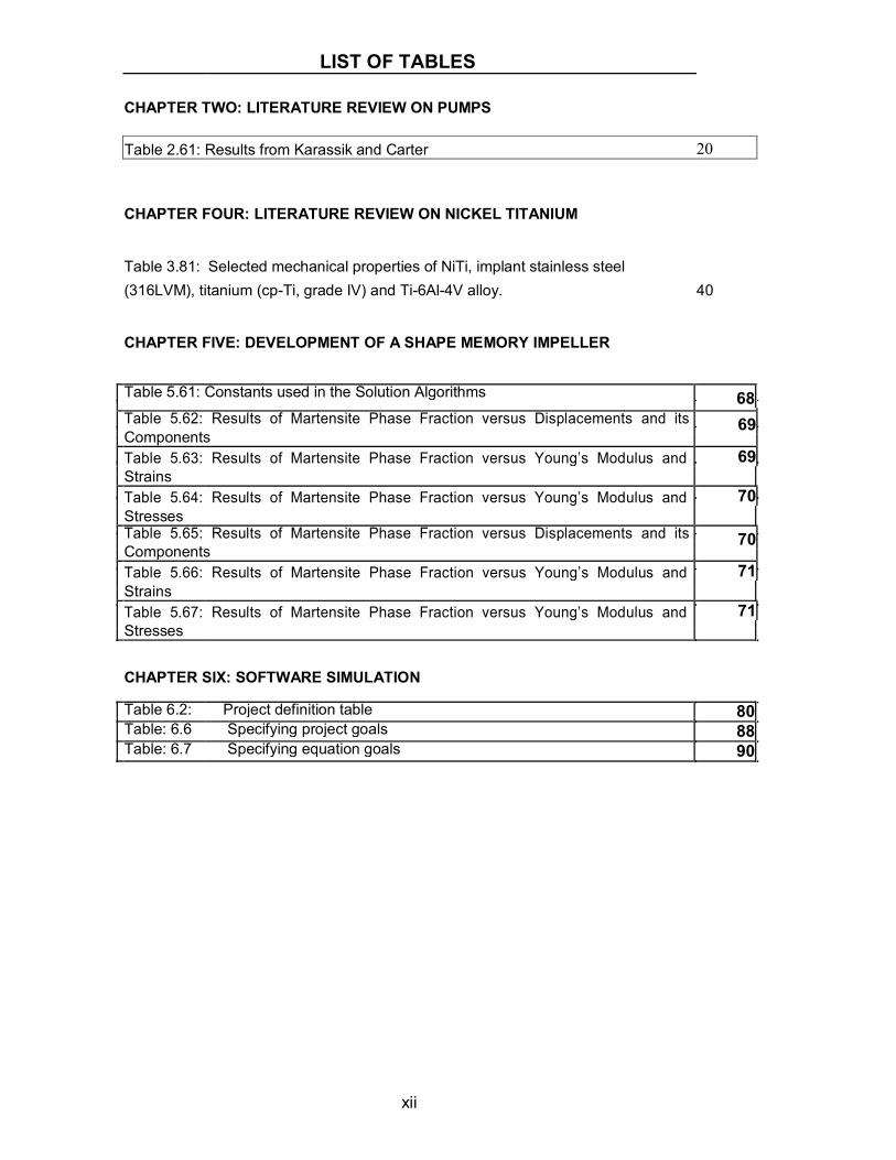
Table 2.61: Results from Karassik and Carter 20
CHAPTER FOUR: LITERATURE REVIEW ON NICKEL TITANIUM
Table 3.81: Selected mechanical properties of NiTi, implant stainless steel(316LVM), titanium (cp-Ti, grade IV) and Ti-6Al-4V alloy. 40
CHAPTER FIVE: DEVELOPMENT OF A SHAPE MEMORY IMPELLER
Table 5.61: Constants used in the Solution Algorithms 68Table 5.62: Results of Martensite Phase Fraction versus Displacements and its 69ComponentsTable 5.63: Results of Martensite Phase Fraction versus Young’s Modulus and 69StrainsTable 5.64: Results of Martensite Phase Fraction versus Young’s Modulus and 70StressesTable 5.65: Results of Martensite Phase Fraction versus Displacements and its 70ComponentsTable 5.66: Results of Martensite Phase Fraction versus Young’s Modulus and 71StrainsTable 5.67: Results of Martensite Phase Fraction versus Young’s Modulus and 71Stresses
CHAPTER SIX: SOFTWARE SIMULATION
Table 6.2: Project definition table 80Table: 6.6 Specifying project goals 88Table: 6.7 Specifying equation goals 90
xii

APPENDICES
APPENDIX A1: FULL REPORT ON INLET ANGLE 300 OUTLET ANGLE 300 106
APPENDIX A2: FULL REPORT ON INLET ANGLE 300 OUTLET ANGLE 350 115
APPENDIX A3: FULL REPORT ON INLET ANGLE 300 OUTLET ANGLE 400 124
APPENDIX A4: FULL REPORT ON INLET ANGLE 300 OUTLET ANGLE 41.50 132
APPENDIX A5: FULL REPORT ON INLET ANGLE 300 OUTLET ANGLE 420 140
APPENDIX A6: FULL REPORT ON INLET ANGLE 300 OUTLET ANGLE 42.50 149
APPENDIX A7: FULL REPORT ON INLET ANGLE 300 OUTLET ANGLE 440 157
APPENDIX A8: FULL REPORT ON INLET ANGLE 300 OUTLET ANGLE 450 166
APPENDIX A9: FULL REPORT ON INLET ANGLE 300 OUTLET ANGLE 460 175
APPENDIX A10: FULL REPORT ON INLET ANGLE 300 OUTLET ANGLE 480 183
APPENDIX A11: FULL REPORT ON INLET ANGLE 300 OUTLET ANGLE 500 192
APPENDIX A12: FULL REPORT ON INLET ANGLE 300 OUTLET ANGLE 550 201
APPENDIX A13: FM21 LABORATORY RESULTS 210
APPENDIX A14: FM21 LABORATORY RESULTS 212
APPENDIX A15: FULL REPORT ON INLET ANGLE 300 OUTLET ANGLE 300 214
APPENDIX A16: FULL REPORT ON INLET ANGLE 300 OUTLET ANGLE 350 223
APPENDIX A17: FULL REPORT ON INLET ANGLE 300 OUTLET ANGLE 400 232
APPENDIX A18: FULL REPORT ON INLET ANGLE 300 OUTLET ANGLE 450 241
APPENDIX A19: FULL REPORT ON INLET ANGLE 300 OUTLET ANGLE 500 250
xiii

CHAPTER ONE: OVERVIEW OF THE PROJECT 1
CHAPTER ONE
OVERVIEW OF THE PROJECT
1.1 Introduction
One of the major parameters used to analyse the performance of a pump is
the mass flow rate of fluid through the pump. For incompressible flow, it is
more common to use Volume flow rate rather than mass flow rate. [36][42]
The type of pumping system (technical design) determines its efficiency as it
relates to the torque on the system, power at pump inlet relative to outlet
power and also inlet flow velocity and outlet flow velocity comparatively.
A smart impeller is one that should change its configuration to match its
system’s working conditions depending on the temperatures or loading
condition in which it is working.[36]
On the commercial side there are smart automobiles and more recently, smart
appliances have also begun to appear. On the industrial side there is smart
instrumentation, smart control valves and smart motors. The pump industry is
behind the times in incorporating the use of computer technology to operate,
control and protect pumps and their systems. Certainly over the past few
decades, significant progress has been made in the areas of pump hydraulics,

CHAPTER ONE: OVERVIEW OF THE PROJECT 2
mechanical design and applications through the use of computerized tools
such as computational fluid dynamics (CFD) and finite element analysis
(FEA). However, only recently have manufacturers begun to develop “smart”
pumps which incorporate microprocessors as part of their normal function.
[36]
A smart pumping system by definition must be capable of knowing when to
adjust itself to system changes without manual intervention. The system must
also be fault tolerant. Fault tolerance enables the system to recognize and
safeguard itself from operating under conditions that may reduce its life.[36]
Adverse conditions such as dry running, operating against a closed suction or
discharge valve and cavitations must all be recognized and reacted to before
damage occurs. The system must also be capable of understanding when the
system transient or unusual operating condition has cleared; thereby allowing
normal pump operation to resume.
1.2 Background
A typical example, a “smart” pumping system consists of a pump, variable
speed drive, instrumentation, microprocessor and special software [36]. The
pump can be any standard centrifugal pump (See figure 1.21 and 1.22 below)
fitted with instrumentation to measure suction pressure, suction temperature,
discharge pressure and pump flow.
All of the hydraulic characteristics of the pump, fluid characteristics, user
control parameters, alarm settings and pump control software reside on the
microprocessor of the smart controller. The pump control software enables
the controller to sense pump and process conditions and react accordingly.
These systems can be designed to maintain constant values of speed,
capacity, pressure, level or pH and can be controlled either locally or through
a distributed control system (DCS). [36]

CHAPTER ONE: OVERVIEW OF THE PROJECT 3
.
Numerous pump and impeller designs have been conceptualised to match the
different applications in industries. See figure 1.23 to figure 1.28 below for
some design configurations. Despite all the differences in configuration, blade
Figure 1.21: Pump in pumping mode showing impeller
Figure1.22: A cross section of a centrifugal pump

CHAPTER ONE: OVERVIEW OF THE PROJECT 4
angle, size, shape and impeller variation, more and more impellers are being
designed everyday to perform specific applications.
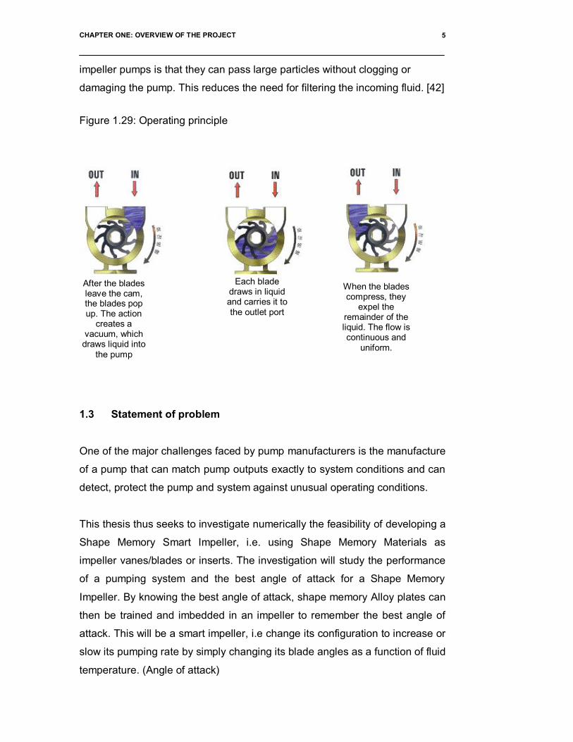
Flexible impeller pumps have been widely used in the marine industry and
provide an efficient solution to most marine pumping needs. The primary
advantage of a flexible impeller pump is its self-priming capability.[42] As the
vanes of the impeller are depressed and rebound, they create their own
vacuum drawing fluid into the pumps (See operating principle in figure 1.29
below).
A dry pump can lift water up to as much as 3 meters. Thus a flexible impeller
pump being used in bilge, deck wash, or engine cooling need not be located
below the water line or be manually primed [42]. An added feature of flexible
Figure: 1.23 Figure: 1.24 Figure: 1.25
Figure: 1.26 Figure: 1.27 Figure: 1.28
CHAPTER ONE: OVERVIEW OF THE PROJECT 5
impeller pumps is that they can pass large particles without clogging or
damaging the pump. This reduces the need for filtering the incoming fluid. [42]
Figure 1.29: Operating principle
1.3 Statement of problem
One of the major challenges faced by pump manufacturers is the manufacture
of a pump that can match pump outputs exactly to system conditions and can
detect, protect the pump and system against unusual operating conditions.
This thesis thus seeks to investigate numerically the feasibility of developing a
Shape Memory Smart Impeller, i.e. using Shape Memory Materials as
impeller vanes/blades or inserts. The investigation will study the performance
of a pumping system and the best angle of attack for a Shape Memory
Impeller. By knowing the best angle of attack, shape memory Alloy plates can
then be trained and imbedded in an impeller to remember the best angle of
attack. This will be a smart impeller, i.e change its configuration to increase or
slow its pumping rate by simply changing its blade angles as a function of fluid
temperature. (Angle of attack)
After the bladesleave the cam,the blades popup. The action
creates avacuum, which
draws liquid intothe pump
Each bladedraws in liquidand carries it tothe outlet port
When the bladescompress, they
expel theremainder of theliquid. The flow iscontinuous and
uniform.

CHAPTER ONE: OVERVIEW OF THE PROJECT 6
1.4 Objectives of the Study
1.4.1 Primary Objective
The primary objective of this study is the conceptualisation a Shape Memory
Smart Centrifugal Impeller for use in conditions where a slight fluctuation in
the environmental temperature conditions may lead to detrimental
consequences to the entire closed system. An example of such a system
could include that of the cooling system in a nuclear reactor.
1.4.2 Sub-Objectives
In order to achieve the primary objective, a few sub-objectives have to be
realized. These include:
To understand the operation and corresponding analytical solution for a
given pumping situation,
o The system studied and investigated is the FM21 centrifugal
pump demonstration unit. See figure 3.11 (Top view) and figure
3.12 (side view) below [40]. This system was used because of
its variable control advantages as will be seen in chapter 4.
o Investigate and determine the performance of the FM21
centrifugal pump demonstration unit system in (i) above as will
be seen in Appendix A13 and A14
To determine analytically and numerically the optimum conditions for a
specific pumping condition, i.e.
o Optimum impeller blade inlet angle with corresponding outlet
angle and efficiency
o Optimum impeller blade inlet angle with corresponding outlet
angle and impeller outlet velocity
o Optimum impeller blade inlet angle with corresponding outlet
angle and fluid flow rate through the impeller

CHAPTER ONE: OVERVIEW OF THE PROJECT 7
o Optimum impeller blade inlet angle with corresponding outlet
angle and impeller shaft torque
o Optimum impeller blade inlet angle with corresponding outlet
angle with least eddy formation in the impeller system.
To conceptualize a Shape Memory Smart Impeller using NiTi Shape
Memory Alloys
To use CFD analyses in order to validate analytical solutions.
1.5 Research Methodology
A numerical investigation into the feasibility of using a smart impeller to study
the performance of a pumping system and the best angle of attack for a
Shape Memory Impeller.
By using advanced computer simulation software, Engineering Fluid
Dynamics (EFD), a system will be designed using Solid works in which the
flow rate (efficiency) of the outlet fluid pumped by the variable outlet angle of
the impeller will be measured. The outlet angle is gradually increased while
the flow rate (efficiency) is captured at each outlet angle. All other
configurations will be kept constant (e.g., inlet angle, flow velocity at inlet, etc)
A graph of variable outlet angle versus efficiency will be drawn. Analytical
results will be compared with simulation results from EFD. The goal will be
realisation of an optimum angle of attack, with increased efficiency with
decrease in power or torque on the impeller. Perceptibly, a decrease in the
angle of attack should decrease efficiency and an increase in the angle of
attack, should increase efficiency.
In real time pumping systems, this variation can then be achieved by the
variation in the trained memory plates imbedded in our impeller reacting
according to temperature changes in the pumping system.
This smart pumping system will be capable of knowing when to adjust itself to
temperature changes without manual intervention. The system will also be

CHAPTER ONE: OVERVIEW OF THE PROJECT 8
capable of responding when the system transient or unusual operating
condition has cleared; thereby allowing normal pump operation to resume.
i) Experimental analysis:
The initial step was to study the pumping Fm21 rig and
performing 100 tests. Data was captured, inlet flow, power in,
power out etc and tabulated on a table as seen in Appendix A13
and A14.
This was done using a series of configurations so that only one
impeller was functional.
The rig was then dismantled carefully and the impeller was
removed and studied.
All dimensions of this impeller were measured to two decimal
places and drawn in 3D view using Solid works.
ii) Analytical algorithms:
Using the dimensions measured in (i) above and data collected
in (i) above to perform, analytical calculations to determine the
performance of the impeller.
At the same time analytical calculations were also made while
varying the outlet angle and keeping the inlet constant.
The above analytical algorithms were supported by MATLAB
and Microsoft Excel.
MATLAB is a high-performance language for technical
computing. It integrates computation, visualization, and

CHAPTER ONE: OVERVIEW OF THE PROJECT 9
programming in an easy-to-use environment where problems
and solutions are expressed in familiar mathematical notation.
Typical uses include Math and computation Algorithm
development Data acquisition Modelling, simulation, and
prototyping Data analysis, exploration, and visualization
Scientific and engineering graphics Application development,
including graphical user interface building MATLAB is an
interactive system whose basic data element is an array that
does not require dimensioning. This allows you to solve many
technical computing problems, especially those with matrix and
vector formulations, in a fraction of the time it would take to write
a program in a scalar noninteractive language such as C or
Fortran. The name MATLAB stands for matrix laboratory.
MATLAB was originally written to provide easy access to matrix
software developed by the LINPACK and EISPACK projects.
Today, MATLAB engines incorporate the LAPACK and BLAS
libraries, embedding the state of the art in software for matrix
computation. MATLAB has evolved over a period of years with
input from many users. In university environments, it is the
standard instructional tool for introductory and advanced
courses in mathematics, engineering, and science. In industry,
MATLAB is the tool of choice for high-productivity research,
development, and analysis. MATLAB features a family of add-on
application-specific solutions called toolboxes. Very important to
most users of MATLAB, toolboxes allow you to learn and apply
specialized technology. Toolboxes are comprehensive
collections of MATLAB functions (M-files) that extend the
MATLAB environment to solve particular classes of problems.
Areas in which toolboxes are available include signal
processing, control systems, neural networks, fuzzy logic,
wavelets, simulation, and many others.
Performance graphs were plotted for both Excel and MATLAB
algorithms.

CHAPTER ONE: OVERVIEW OF THE PROJECT 10
iii) Solid works
Solid Works software provides part and assembly
configuration management capabilities, which can accelerate
the entire product design process. Configuration
management allows you to:
Store information about a part or assembly and its
components in a particular state.
Create multiple design variations of a part or assembly
model within a single document.
Develop and manage families of models with different
dimensions, components, properties or other parameters
The impeller, extracted from the FM21 unit was drawn to scale
in this 3D software. While keeping the inlet angle constant, the
outlet angle was varied for each different impeller. A constant
interval of 5 degrees was used for the first simulation, then 2
degrees and lastly 0.5 degrees.
Each of the varied impeller configurations were made into a
completely separate assembly and saved while waiting to be
simulated separately in EFD
iv) Engineering fluid Dynamics (EFD)
The assemblies compiled in iii) above are then imported into
EFD and simulated using the simulation algorithms.
Obtaining reliable early findings about flow and heat transfer
processes is often a crucial criterion for the success of a
development project. In some cases, concrete information about
the physical flow and heat transfer functions in a future design or

CHAPTER ONE: OVERVIEW OF THE PROJECT 11
method is required right from the definition phase. In the age of
Product Lifecycle Management (PLM) strategies, there is no
longer any viable alternative to computer-based simulation.
Flow calculations that are not able to keep pace with the general
progress of a project are less useful as development tools. As a
result, the efficiency of simulation calculations – not only flow
simulations – is determined to a large extent by the total
processing time required. This begins with the provision of 3D
CAD data for the design to be analysed and ends with the
presentation of results and conclusions to the decision-making
bodies. Under practical conditions in development and design
departments, this challenge can only be met using specially
tailored calculation tools. These tools must be designed in such
a way as to free the project engineer as far as possible from
specific calculation activities and allow him to concentrate
exclusively on the actual resolution of the physical and technical
issues. Crucial elements here include handling of the CAD data
for generation of the geometric model to achieve the maximum
possible integration, automatic grid technology, stability and
reliability of the mathematical algorithms through intelligent
solution control and efficient evaluation and documentation of
results.
The initial version of the geometry to be analysed normally
exists as a 3D CAD data file. This data can be most easily used
for a simulation if the simulation program is integrated into the
CAD system and can directly use the system’s geometry
functions. The Engineering Fluid Dynamics (EFD) software from
NIKA for flow and heat transfer simulation is integrated into solid
works as a workbench as an additional module and uses these
systems’ respective user interfaces to access the same features
as are available for the geometry model itself. Changes and
optimisations to the geometry based on findings from the

CHAPTER ONE: OVERVIEW OF THE PROJECT 12
simulation calculations can be made directly in the CAD system
using the familiar modeling functions. However, there are also
various areas where more universal handling of 3D geometry
data is required. For example, many system suppliers and
engineering service providers process geometry data for
simulations in a range of data formats and expect the data to be
seamlessly transferred using import interfaces for original data
from all major 3D CAD systems and using interfaces for
universal standard formats such as STEP, IGES and VDAFS. It
is important that the parameters of the initial version of the
imported components and assemblies are changed or
supplemented for subsequent analyses and can be returned to
their original format for direct processing in the original system.
To meet these requirements, NIKA has developed the EFD.Lab
program system, which combines the Engineering Fluid
Dynamics technology for flow calculations and a latest
generation parametric volume modeler with a full range of
interfaces. EFD.Lab thus provides comprehensive CAD links for
almost all important 3D CAD systems.
a) Automatic Grid Generation
The finite volume method has established itself as the
fundamental calculation method for simulating flow, heat and
material transfer. This method requires a calculation grid in the
area to be analysed. It is crucial that this grid is of high quality in
terms of flow calculations. The criteria include automatic
generation of hexahedron cells over the entire calculation area
and a sufficient grid density in areas that are critical in terms of
the fluid mechanics, without allowing the calculation to become
inefficient due to unnecessarily large models. If the 3D CAD
models created for the mechanical design and production are
now used for grid generation, a problem occurs: the area to be
calculated – the space filled with liquid or gas – is not normally

CHAPTER ONE: OVERVIEW OF THE PROJECT 13
modelled as a separate solid and is not therefore available for
grid generation. To overcome this, the EFD programs can
automatically identify both the enclosed internal flow space and
the outer flow area, as well as the solid areas of different
materials involved in heat transfer. A grid of hexahedron
elements is then automatically generated for the entire
calculation area using RAM (Rectangular Adaptive Mesh)
technology, and the grid density is automatically adjusted at
geometrically and physically critical areas.
b) Automated Evaluation of Results UsingStandard Software
Efficient evaluation and documentation of the calculation results
is another important factor in the total processing time and thus
in the total costs of a flow simulation. With MS Office, the PC
platform provides a standard for creating documents or
presentations and evaluating numerical material. The
combination of MS Office with a flow simulation program
integrately into a CAD system or a volume modeller opens up
new possibilities when it comes to providing effective and
practical access to the calculation results. For example, result
data along a CAD curve can be extracted and automatically
presented and evaluated as a chart or table in MS Excel. Users
can adapt the templates used to meet their own individual
corporate Identity, allowing presentation-ready documents to be
created.
The performance of each impeller is determined and plotted.
v) Feasibility:

CHAPTER ONE: OVERVIEW OF THE PROJECT 14
The feasibility study is done with graphical representation.
Comparing the different algorithms and contrasting.
1.6 Overview of Thesis
Chapter 2 provides an overview of pumping systems and specifically
centrifugal pumping systems. Chapter 3 gives an overview of the centrifugal
pumping system used to develop the specific pumping scenario used to
develop the Shape Memory Smart Impeller, while Chapter 4 provides a
background to Shape Memory Alloys as well as the mechanisms or
phenomenon used in the conceptualisation of the Shape Memory Alloy Smart
Impeller. Chapter 5 provides an analytical description of the pumping system
and introduces the concepts used to conceptualise the Shape Memory Smart
Impeller. It further describes analytically the operation of the impeller and
draws conclusions on its feasibility. Chapter 6 provides a description of the
CFD software used, and Chapter 7 provides a discussion of CFD results
obtained. Chapter 8 provides conclusions and makes recommendations for
future studies of the Shape Memory Smart Impeller.

CHAPTER TWO: LITERATURE REVIEW ON PUMPS 15
CHAPTER TWO
LITERATURE REVIEW ON PUMPS
2.1 Choice of Pump
Pumping may be defined as the addition of energy to a fluid to move it from
one point to another. It is not, as frequently thought, the addition of pressure.
Energy is the capacity to do work, and adding it to a fluid causes the fluid to
do work. By definition, a centrifugal pump is a device whose primary purpose
is to produce pressure by accelerating fluid particles to high velocity providing
them with velocity energy [3]
The design will focus on centrifugal pumps because they are commonly used.
They can be found around our home-in dishwashers, hot tubs, clothes
washers and dryers, fluid dryers, vacuum cleaners, kitchen exhaust hoods,
bathroom exhaust pumps, leaf blowers, furnaces, etc. They are also used in
cars –water pump in engine, the are blower in heater/fluid condition.
Centrifugal pumps are ubiquitous in industry as well; they are used in building
ventilation systems, washing operations, and in numerous other industrial
operations in which fluid is pumped. [3]

CHAPTER TWO: LITERATURE REVIEW ON PUMPS 16
2.2 Functionality of the centrifugal pump
A centrifugal pump briefly, is a machine consisting of rotating vanes enclosed
within a housing. In a centrifugal flow pump, fluid enters axially (in the same
direction as the axis of the rotating shaft.) in the centre of the pump, after
which it encounters the rotating blades. The vanes impart energy to a fluid
through centrifugal force. It acquires tangential and radial velocity by
momentum transfer with the impeller blades, and additional radial velocity by
centrifugal forces, which are actually a lack of sufficient centripetal forces to
sustain circular motion. The fluid leaves the impeller after gaining both speed
and pressure as it is flung radially outward into a scroll ( also called volute)
and is discharged radially (or tangentially) along the outer radius of the pump
casing. The scroll is a snail-shape diffuser whose purpose is to decelerate the
fast moving fluid leaving the trailing edges of the impeller blades, thereby
further increasing the fluid‘s pressure, and to combine and direct the flow from
all the blade passages toward a common outlet. [37]
2.3 Inlet and outlet diameter of a centrifugal pump.
If the inlet and outlet diameters are the same the average flow speed at the
outlet is identical to that at the inlet. Thus, it is not necessarily the speed, but
the pressure that increases from inlet to outlet through a centrifugal pump
[37].
2.4 Blade Geometry
There are three types of centrifugal pump that warrant discussion, based on
the impeller geometry;[37]
1. Backward-inclined blades
2. Radial blades(Straight blades)
3. Forward inclined blades

CHAPTER TWO: LITERATURE REVIEW ON PUMPS 17
2.4.1 Backward inclined blades
Centrifugal pumps with backward inclined angles are the most common. This
yields the highest efficiency of the three because fluid flows into and out of the
blade passages with the least amount of turning. Fluid foil shaped blades; will
yield similar performance but even higher efficiency. The pressure rise is
intermediate between the two types of centrifugal pumps [37].
2.4.2 Straight blades
Centrifugal pumps with radial blades (also called straight blades), have the
simplest geometry and produce the largest pressure rise of the three for a
wide range of volume flow rates, but the pressure rise decreases rapidly after
the point of maximum efficiency[37].
2.4.3 Forward inclined blades.
Forward inclined blades produce a pressure rise that is nearly constant, albeit
lower than that of radial or backward-inclined blades, over a wide range of
volume flow rates. Centrifugal pumps with forward inclined blades generally
have more blades, but the blades are smaller. Centrifugal pumps with forward
inclined blades generally have a lower maximum efficiency than do straight
blade- pumps [37].
Radial and backward are preferred for applications where one needs to
provide volume flow rate and pressure rise within a narrow range of values. If
a wider range volume flow rates and/or pressure rises are desired, the
performance of radial and backward-inclined pumps may not be able to satisfy
the new requirements; these types of pumps are less forgiving(less robust)
the performance of forward-inclined pumps is more forgiving and
accommodates a wider variation, at the cost of lower efficiency and less
pressure per unit of power input. If a pump is needed to produce large
pressure rise over a wide range of volume flow rates, the forward-inclined
centrifugal pump is attractive.

CHAPTER TWO: LITERATURE REVIEW ON PUMPS 18
Net head and brake horsepower performance curves for these three types of
centrifugal pump are compared below. The curves have been adjusted such
that each pump achieves the .same free delivery (maximum volume flow rate
at zero net head). These are quantitative sketches for comparison only. Actual
measured performance curves may differ significantly in shape, depending on
details of the pump design.
2.5 Velocity vectors through the blades
The inclination of the impeller blades (backward, radial or forward) the velocity
vectors can be analyse mathematically and using Matrix
Laboratory.(analytical algorithm)
Normally the actual flow may be unsteady, fully three-dimensional, and
perhaps compressible. But for simplicity, the research will consider steady
flow rate in both absolute reference frame and in relative reference rotating
with the impeller. Only incompressible flow will be considered. In addition,
only radial or normal velocity component and the circumferential or tangential
velocity from blade inlet to outlet will be considered. We do not consider the
axial velocity component, in order words, although there is a nonzero axial
component of velocity through the impeller, it does not enter our analysis.
2.6 Variation in impeller diameter
The performance of a pump changes if the impeller is reduced in diameter
(within a limit dependent upon the impeller design) from the characteristics of
a larger impeller.
Figure 2.41: Horse power performance curves

CHAPTER TWO: LITERATURE REVIEW ON PUMPS 19
The diameter of an average impeller can be cut down by 20 per cent of its
original maximum value without adverse effect. Cutting it down to less than 80
per cent will generally result to a lower efficiency. Its has been documented
that if a impeller is cut in diameter, the flow rate varies as the impeller
diameter and at the same time the head varies as the square of the impeller
diameter and the power varies as the cube of the of the impeller diameter.
That is;
Q = Q1(D/D1)
H = H1(D/D1)2
P = P1(D/D1)3
D1= Original diameter
D = Cut down diameter
Q1= Flowrate with D1 impeller.
Q= Flowrate with D impeller.
H1= Head with D1 impeller at Q1
H= Head with D impeller at Q
P1= Power with corresponding D1, H1 and Q1
P= Power with corresponding D, H and Q
Experiments conducted by Karassik and Carter, a pump was tested at 1800
rpm (with impeller diameter of 14.75 inch), if the diameter is reduce to 14 inch
in diameter, results were as follows [38]

CHAPTER TWO: LITERATURE REVIEW ON PUMPS 20
EFFECT OF CHANGE IN IMPELLER DIAMETER
0
50
100
150
200
250
3.797 3.322 2.847 1.898 949 0FLOW RATE IN gpm
HEA
D IN
ftTable 2.61: Results from Karassik and Carter
2.7 Blade aerodynamic design.
As mentioned previously the choice of correct twist and of special fluid foil
sections to reduce compressibility losses are of major importance in modern
blades design [30]. However other considerations still remain to be studied
with care if the efficiency of the blade is to be kept at its maximum under
severe operating conditions.
Flowrate (gpm) Head (ft) Power (bhp) Efficiency (%)
3.797 141.5 162 83.7
3.322 165.3 158.2 87.6
2.847 180.7 149.2 87.0
1.898 199 121.6 78.4
949 206 91.5 54.0
0 207.4 65.4 0
Figure 2.61: Graph of head versus flow rate

CHAPTER TWO: LITERATURE REVIEW ON PUMPS 21
2.8 Centrifugal and aerodynamic twisting
In a variable-pitch impeller as described later, the blades are turned in the hub
about their longitudinal or pitch-change axis. Clearly the mechanism provided
to produce this pitch change must be capable of exerting sufficient force to
overcome any mechanical or aerodynamic opposing force set up by the
blades themselves [30].
The “mechanical force” involved is known as Centrifugal Twisting Moment
(C.T.M). This force is closely allied to the normal centrifugal force acting on
the blades when the impeller is rotating about the shaft. It is the turning couple
produced due to the inclination of the blade section at an angle to the SMA of
rotation and results in the natural tendency for any blade, when rotating
turned about its longitudinal axis towards zero pitch so that the blades section
are turned in to the SMA blade rotation[30] .
2.9 Thrust and torque forces.
The main factor that determines the force developed by an aerofoil section is
the angle at which it is inclined to the relative flow, i.e. the angle of attack.
Thus, for the blade section to develop the requisite aerodynamic force for
propulsion, each section along the blade must be inclined at the appropriate
angle of attack to the relative flow direction pertaining to the section hence
knowing angle of attack is a simple mater to indicate the force developed [37].

CHAPTER THREE: PUMPING SYSTEM 22
CHAPTER THREE
PUMPING SYSTEM
3.1 The pumping system.
The system used is the FM21 centrifugal pump demonstration unit. This
system is utilised in the Department of Mechanical Engineering of the Cape
Peninsula University of Technology as a demonstration unit for undergraduate
students. See figure 3.11 (Top view) and figure 3.12 (side view) below [40].
Figure: 3.11: FM21 centrifugal pump testing unit (top view)

CHAPTER THREE: PUMPING SYSTEM 23
The equipment comprises two identical centrifugal water pumps (5 and 23)
driven by electric motors (4 and 25) which are mounted on a support plinth (9)
together with a clear acrylic reservoir (11) and associated interconnecting
pipework for continuous circulation. Configurations of either series, parallel or
single pump operation can be set using the appropriate valves (7, 8, 20 and
21). Clean water is used as the operating fluid and a drain valve (10) at the
base of the reservoir allows the water to be drained after use.
Appropriate sensors are incorporated on the unit to facilitate analysis of the
pump performance when connected to a suitable computer via an IFD
Interface Console. In addition to the tappings lines required by the pressure
sensors, additional tappings are included in the pipework at the pressure
tapping points to allow appropriate calibration instruments to be connected.
The flow of water through the centrifugal pumps is regulated by a flow control
valve (18) installed in the discharge pipework of the unit. Adjustment of this
Figure: 3.12: FM21 centrifugal pump testing unit(side view)

CHAPTER THREE: PUMPING SYSTEM 24
valve allows the head/flow produced by the pumps, either separately of
combined, to be varied.
The following sensors are used to monitor the performance of the pumps:-
3.2 Differential pressure sensor SPW1:
This comprises of a pressure sensitive device with appropriate signal
conditioning all contained in a protective case (12) and used to measure
pressure developed across the orifice plate (15) installed in the discharge
pipework of the pump(s). The volume flow rate of water for either series,
parallel or single pump operation can be calculated using this measurement.
The sensor is connected to the appropriate tappings in the pipework using
flexible tubing. Additional tappings (14 and 16) are provided for the connection
of appropriate instrumentation to facilitate calibration of the differential
pressure sensor.
3.3 Differential pressure sensor SPW3 (2 off):
This comprises of a pressure sensitive piezoresistive device with appropriate
signal conditioning all contained in a protective case (19 and 22) and is used
to measure the difference in pressure between the inlet and outlet of each
centrifugal pump. The head developed by the pumps can be calculated from
this measurement.
The sensors are connected to the appropriate tappings in the ducts using
flexible tubing.
3.4 Rotational speed sensor SSO1 (2 off):
This comprises of a reflective infra-red opto switch (1 and 2) on a remote lead
with appropriate signal conditioning in a protective case (3 and 24). They are
used to measure the rotational speed of each motor/impeller.

CHAPTER THREE: PUMPING SYSTEM 25
Each opto switch is mounted on a bracket adjacent to the end of each motor
shaft which incorporates a reflective strip to facilitate measurement of the
rotational speed.
3.5 A temperature sensor STS1:
This comprises of a temperature sensitive semiconductor device on a remote
lead with appropriate signal conditioning in a protective case (6) and is used
to measure the temperature of the water entering the first centrifugal pump.
The sensor is inserted through the wall of the pipe using a waterproof gland.
The sensor may be removed from the gland for the purpose of calibration
using appropriate equipment.
3.6 SWA1 Wattmeter
In addition to the above sensors, which are all permanently attached to the
FM21 unit, an Integrating Wattmeter (SWA1) (See Figure 3.61: SWA1
integrated wattmeter) may be connected to the power line of each pump:
The wattmeters are connected between the mains lead from each pump and a
suitable power supply. This facilitates the measurement of the electrical power
supplied to each motor.
The Armfield SWA1 Integrating Wattmeter provides power of between 0 and
500W, continuously variable using the Variac Dial.
The meter signal is available on a ‘phone’ connector, giving a 0 to 5V output.
The Wattmeter is connected between the mains lead from the pump and a
suitable power supply to facilitate measurement of the electrical power
supplied to the motor.

CHAPTER THREE: PUMPING SYSTEM 26
3.7 The IFD6 Interface
The IFD6 interface is used to transfer data from the heat exchanger under test
to a computer.
It connects to the computer’s USB port.
The sensors on the FM21 are connected using special phone
sockets.
Figure 3.61: SWA1 integrated wattmeter
Figure 3.71: IFD6 interface

CHAPTER THREE: PUMPING SYSTEM 27
3.8 Operation of the pump
For the pump operation, only a single pump operation was considered. All
tappings lines in the pipework of the FM21 are connected to appropriate
sensors or blanked. The differential pressure sensor SPW1 (12) should be
connected directly across the orifice plate assembly (15) and the differential
pressure sensor SPW3 (19) should be connected between the inlet and outlet
of the first pump (5).
Open the inlet valve (8) and close the outlet control valve (18). Ensure that the
unit configuration valves (20 and 21) are closed and (7) is open.
Ensure the drain valve (10) at the base of the reservoir is fully closed then fill
the reservoir with clean, cold water.
Connect the mains lead from the motor of the first centrifugal pump to the
Integrating Wattmeter SWA1. Connect the SWA1 to the MAINS OUTPUT on
IFD.
Switch on the mains supply. Check that the pump operates. Open the outlet
flow control valve fully and allow water to circulate until all air bubbles are
expelled. Switch off pump.
Connect each of the sensor conditioning boxes to the appropriate sensor
sockets on the IFD, using the numbered connecting leads, as follows:-
· Channel 1 to sensor SPW1 (12)
· Channel 2 to sensor STS1 (6)
· Channel 3 to sensor SPW3 (19)
· Channel 4 to sensor SSO1 (3)
· Channel 5 to Integrating Wattmeter SWA1

CHAPTER THREE: PUMPING SYSTEM 28
3.9 Practical Sampling.
The picture below (See FM21 laboratory demonstration unit) was taken before
sampling.
This single pump operation is a closed loop system. Using the Armfield
software, configuration was made to capture data for an hour. See Armfield
operating window figure 3.92 to Figure 3.94 below
Figure 3.91: FM21 laboratory demonstration unit
Figure 3.92: Armfield software window during sampling

CHAPTER THREE: PUMPING SYSTEM 29
Figure 3.93: Armfield software sample configuration window during sampling.
Figure 3.94: Armfield software IFD channel status and history window during sampling.

CHAPTER THREE: PUMPING SYSTEM 30
3.10 Nomenclature and Practical Calculations
The variables obtained from the sensors on the equipment are:-
Symbol Term Unitsdpo Pressure drop across the orifice plate Pa
(Pascals)(1Pa=1N/m2)
dps Pressure drop across the pump Pa (Pascals)
Ta Water temperature at pump inlet °C (Celsius)
Pe Input power to the motor W (Watts)
Constants used in the calculations:-
Symbol Term Value Unitsd Orifice plate diameter 0.024 m
Cd Orifice discharge coefficient 0.61
g Gravitational acceleration 9.81 m/s²
A1 Cross sectional area of the pump inlet 0.00029865 m²
A2 Cross sectional area of the pump outlet 0.00029865 m²
n Rotational speed of the pump Hz=45=2700rpm=282.74rad/s
Calculated variables:-
Symbol Term UnitsQv Volume flow rate m³/s
v1 Velocity in the duct at pump inlet m/s
v2 Velocity in the duct at pump outlet m/s

CHAPTER THREE: PUMPING SYSTEM 31
100 sample data was capture at interval of one minute. See Appendix A13
and A14 for laboratory results.
The Euler Head and the velocity head was cancelled out so that only the
pressure head can be measure. That is, only the impeller efficiency.
The below equations were used and it confirm those with Laboratory result as
seen in Appendix A13 and A14
E = (Pressure at outlet - Pressure at inlet) x Q/torque/Angular velocity
OR
E = (Pressure at outlet - Pressure at inlet) / Density/gravity

CHAPTER FOUR: LITERATURE REVIEW ON NiTi SHAPE MEMORY ALLOYS 32
CHAPTER FOUR
LITERATURE REVIEW ON NITI SHAPEMEMORY ALLOYS
4.1 General Principles of Shape Memory Alloy
Shape memory alloys (SMA) such as Nickel-Titanium (NiTi) are distinguished
by two unusual characteristics, i.e. the shape memory effect and pseudo-
elasticity. The shape memory effect is one in which the material can be
mechanically deformed (seemingly permanently) at a temperature below a
certain transition temperature, but will revert to its original shape upon heating
above the transition temperature. Pseudo elasticity refers to the material’s
ability (at temperatures somewhat above the transition temperature) to be
strained significantly (to strains higher than 6% for nearly equiatomic NiTi.)
and return to its unstrained configuration upon loading via a hysteresis loop. A
diffusionless transformation between two solid state metallurgical phases
called Austenite and Martensite is responsible for both effects and can be
induced by either changes in stress or temperature [39].

CHAPTER FOUR: LITERATURE REVIEW ON NiTi SHAPE MEMORY ALLOYS 33
4.2 General Characteristics of Nickel Titanium
NiTi shape memory metal alloy can exist in a two different temperature-
dependent crystal structures (phases) called martensite (lower temperature)
and austenite (higher temperature or parent phase). Several properties of
austenite NiTi and martensite NiTi are notably different.[39]
When martensite NiTi is heated, it begins to change into austenite (Figure
4.31-A). The temperature at which this phenomenon starts is called austenite
start temperature (As). The temperature at which this transformation is
complete is called austenite finish temperature (Af). When austenite NiTi is
cooled, it begins to transform into martensite. The temperature at which this
transformation starts is called martensite start temperature (Ms). The
temperature at which martensite is again completely reverted is called
martensite finish temperature (Mf) [39]
Composition and metallurgical treatments have dramatic impacts on the
above transition temperatures. From the point of view of practical
applications, NiTi can have three different forms: martensite (at temperatures
below As), stress-induced martensite (at temperatures above Af), and
austenite (at temperatures above Af). When the material is in its martensite
form, it is soft and ductile and can be easily deformed (somewhat like soft
pewter). Superelastic NiTi is highly elastic (rubber-like), while austenitic NiTi
is quite strong and hard (similar to titanium) (Figure 4.31-B). The NiTi material
has all these properties, their specific expression depending on the
temperature in which it is used.[39]
4.3 Hysteresis
The temperature range for the martensite-to-austenite transformation, i.e.
soft-to-hard transition, which takes place upon heating, is somewhat higher
than that for the reverse transformation upon cooling (Figure 4.31-A). The
difference between the transition temperatures upon heating and cooling is
called hysteresis. Hysteresis is generally defined as the difference between

CHAPTER FOUR: LITERATURE REVIEW ON NiTi SHAPE MEMORY ALLOYS 34
the temperatures at which the material is 50 % transformed to austenite upon
heating and 50 % transformed to martensite upon cooling. This difference can
be up to 20-30 °C (Buehler et al. 1967, Funakubo 1987). In practice, this
means that an alloy designed to be completely transformed by body
temperature upon heating (Af < 37 °C) would require cooling to about +5 °C to
fully retransform into martensite (Mf).
4.4 Thermoelastic martensitic transformation
The unique behaviour of NiTi is based on the temperature-dependent
austenite-to-martensite phase transformation on an atomic scale, which is
also called thermoelastic martensitic transformation. The thermoelastic
martensitic transformation causing the shape recovery is a result of the need
of the crystal lattice structure to accommodate to the minimum energy state
for a given temperature (Otsuka & Wayman 1998).[39]
In NiTi, the relative symmetries between the two phases lead to a highly
ordered transformation, where the displacements of individual atoms can be
accurately predicted and eventually lead to a shape change on a macroscopic
scale. The crystal structure of martensite is relatively less symmetric
compared to that of the parent phase.
If a single crystal of the parent phase is cooled below Mf, then martensite
variants with a total of 24 crystallographically equivalent habit planes are
generally created. There is, however, only one possible parent phase
Figure 4.31 A) Martensitic transformation and hysteresis (= H) upon a change of temperature. As =austenite start, Af = austenite finish, Ms = martensite start, Mf = martensite finish and Md = Highest
temperature to strain-induced martensite. Gray area = area of optimal super elasticity, and B) Stress-strainbehaviour of different phases of NiTi at constant temperature.

CHAPTER FOUR: LITERATURE REVIEW ON NiTi SHAPE MEMORY ALLOYS 35
(austenite) orientation, and all martensitic configurations revert to that single
defined structure and shape upon heating above Af. The mechanism by which
single martensite variants deform is called twinning, and it can be described
as a mirror symmetry displacement of atoms across a particular atom plane,
i.e. the twinning plane [39]
While most metals deform by slip or dislocation, NiTi responds to stress by
simply changing the orientation of its crystal structure through the movement
of twin boundaries.
A NiTi specimen will deform until it consists only of the corresponding variant
which produces maximum strain. However, deformation beyond this will result
in classical plastic deformation by slip, which is irrecoverable and therefore
has no “memory effect”. If the deformation is halted midway, the specimen will
contain several different corresponding variants. If such a specimen is heated
above Af, a parent phase with an orientation identical to that existing prior to
the deformation is created from the correspondence variants in accordance
with the lattice correspondences between the original parent phase and each
variant (Figure 4.41). The austenite crystal structure is a simple cubic
structure, while martensite has a more complex rhombic structure. This
phenomenon causes the specimen to revert completely to the shape it had
before the deformation (Andreasen et al. 1987, Gil et al. 1998).
The above phenomenon is the basis of such special properties as the shape
memory effect and superelasticity.
4.5 Shape memory effect
NiTi senses a change in ambient temperature and is able to convert its shape
to a pre-programmed structure. While NiTi is soft and easily deformable in its
lower temperature form (martensite), it resumes its original shape and rigidity
when heated to its higher temperature form (austenite) (Figure 4.41). This is
called the one-way shape memory effect. The ability of shape memory alloys
to recover a preset shape upon heating above the transformation
temperatures and to return to a certain alternate shape upon cooling is known

CHAPTER FOUR: LITERATURE REVIEW ON NiTi SHAPE MEMORY ALLOYS 36
as the two-way shape memory effect. Two-way memory is exceptional. There
is also an all-round shape memory effect, which is a special case of the two-
way shape memory effect.[39]
Figure 4.41: Transformation from the austenite to the martensite phase and shape memory effect. Thehigh-temperature austenitic structure undergoes twinning as the temperature is lowered. This twinned
structure is called martensite. The martensitic structure is easily deformed by outer stress into a particularshape, and the crystal structure undergoes parallel registry. When heated, the deformed martensite
resumes its austenitic form, and the macroscopic shape memory phenomenon is seen.

CHAPTER FOUR: LITERATURE REVIEW ON NiTi SHAPE MEMORY ALLOYS 37
4.6 Superelasticity
Super-elasticity (or pseudo- elasticity) refers to the ability of NiTi to return to
its original shape upon unloading after a substantial deformation. This is
based on stress-induced martensite formation. The application of an outer
stress causes martensite to form at temperatures higher than Ms. The
macroscopic deformation is accommodated by the formation of martensite.
When the stress is released, the martensite transforms back into austenite
and the specimen returns back to its original shape (Figure 4.61). Super-
elastic NiTi can be strained several times more than ordinary metal alloys
without being plastically deformed, which reflects its rubber-like behaviour. It
is, however, only observed over a specific temperature area. The highest
temperature at which martensite can no longer stress induced is called Md.
Above Md NiTi alloy is deformed like ordinary materials by slipping. Below As,
the material is martensitic and does not recover. Thus, super-elasticity
appears in a temperature range from near Af and up to Md. The largest ability
to recover occurs close to Af (Duerig et al. 1996).
Figure: 4.61: Schematic presentation of lattice structure changes caused by outer stress in stainlesssteel or superelastic NiTi alloy. In stainless steel, outer stress first causes reversible Hookian type
changes in the elastic area. In the plastic area, deformation takes place via a mechanism called slip. Thisdeformation is irreversible. In superelastic NiTi alloy, outer stress causes a twinning type of
accommodation which is recovered when outer stress is removed.

CHAPTER FOUR: LITERATURE REVIEW ON NiTi SHAPE MEMORY ALLOYS 38
4.7 Limitations of shape memory and superelastic behavior
About 8% strain can be recovered by unloading and heating. Strain above the
limiting value will remain as a permanent plastic deformation. The operating
temperature for shape memory devices must not move significantly away from
the transformation range, or else the shape memory characteristics may be
altered. A shape memory NiTi implant must be deformed at a temperature
below As (usually < +5 °C). Moreover, the deformation limit determined by
distinctive implant design (sharp angles, etc.) and the intrinsic strain tolerance
of NiTi material must not be disregarded (Otsuka & Wayman 1998).
4.8 Mechanical properties of NiTi
For orthopedic biomaterial applications, the two properties of major
importance are strength (mechanical) and reactivity (chemical). Generally,
there are two basic mechanical demands for the material and design of the
implant. Service stresses must be safely below the yield strength of the
material, and in cyclic loads the service stress must be kept below the fatigue
limit (Figure 4.81).
The mechanical properties of NiTi depend on its phase state at a certain
temperature (Buehler et al. 1967, Van Humbeeck et al. 1998) (Figure 4.41).
Fully austenitic NiTi material generally has suitable properties for surgical
implantation. The common mechanical properties of martensitic and austenitic
NiTi are presented in Table 4.81. There are some exceptional properties that
might be useful in surgery. NiTi has an ability to be highly damping and
vibration-attenuating below As. For example, when a martensic NiTi ball is
dropped from a constant height, it bounces only slightly over half the height
reached by a similar ball dropped above the Af temperature. From the
orthopedic point of view, this property could be useful in, for example,
dampening the peak stress between the bone and the articular prosthesis.
The low elastic modulus of NiTi (which is much closer to the bone elastic

CHAPTER FOUR: LITERATURE REVIEW ON NiTi SHAPE MEMORY ALLOYS 39
modulus than that of any other implant metal) might provide benefits in
specific applications. NiTi has unique high fatigue and ductile properties,
which are also related to its martensitic transformation. These properties are
usually favorable in orthopedic implants. Also, very high wear resistance has
been reported compared to the CoCrMo alloy (Sekiguchi 1987). NiTi is a non-
magnetic alloy. MRI imaging is thus possible. Electrical resistance and
acoustic damping also change when the temperature changes.
Figure: 4.81: E) Schematic presentation of the stress-strain behavior ordinary implant metals. The materialexhibits elastic behavior until sufficient stress is applied to reach the tensile yield strength, at which point
permanent deformation occurs. In the elastic range, the stress-strain ratio determines the elastic modulus. Themetal breaks when the applied stress exceeds the ultimate tensile strength of the particular material

CHAPTER FOUR: LITERATURE REVIEW ON NiTi SHAPE MEMORY ALLOYS 40
NiTi StainlessSteel
Titanium Ti-6Al-4V
Austenitic Martensitic
Ultimate tensile strength (Mpa) 800 - 1500 103 - 1100 483 - 1850 540 - 740 920 - 1140
Tensile yield strength (Mpa) 100 - 800 50 - 300 190 - 1213 390 830 - 1070
Modulus of elasticity (GPa) 70 - 110 21 - 69 190 - 200 105 - 110 100 - 110
Elongation at failure (%) 1 - 20 up to 60 12 - 40 16 8* Lowest and highest values have been compiled from picked references (Buehler l. 1967, Funakubo 1987,
Breme et al. 1998, Van Humbeeck et al. 1998).
4.9 Effect of alloy composition, heat treatment and mechanicalworking on NiTi properties
It is feasible to vary the critical transition temperatures either by small
variations of the Ti/Ni composition or by substituting metallic cobalt for nickel.
Lowering of Af is possible by adding nickel. If nickel is added above 55.6 Wt%,
a stable second phase (Ti-Ni3) forms and the NiTi properties are lost. To
avoid this problem, the cobalt substitution can be used to lower the TTR. The
properties of NiTi can also be greatly modified by mechanical working and
through heat treatment (time and temperature) (Buehler et al. 1967).
4.10 Fabrication
Solid NiTi alloys are manufactured by a double vacuum melting process, to
ensure the quality, purity and properties of the material. After the formulation
of raw materials, the alloy is vacuum induction melted (1400°C). After the
initial melting, the alloy transition temperature must be controlled due to the
sensitivity of the transition temperature to small changes in the alloy
chemistry. This is followed by vacuum arc re-melting to improve the
Table 4.81: Selected mechanical properties of NiTi, implant stainless steel (316LVM), titanium (cp-Ti, gradeIV) and Ti-6Al-4V alloy.

CHAPTER FOUR: LITERATURE REVIEW ON NiTi SHAPE MEMORY ALLOYS 41
chemistry, homogeneity and structure of the alloy. Double-melted ingots can
be hot-worked (800°C) and cold-worked to a wide range of product sizes and
shapes (Andreasen et al. 1987).
Porous NiTi can be made by sintering or using self-propagating high
temperature synthesis, also called ignition synthesis. The possibility to make
composite SMA products (combination with polymers) is under investigation
(Brailovski et al. 1996).
4.11 Programming (Training)
The use of the one-way shape memory or superelastic property of NiTi for a
specific application requires a piece of NiTi to be molded into the desired
shape. The characteristic heat treatment is then done to set the specimen to
its final shape. The heat treatment methods used to set shapes in both the
shape memory and the superelastic forms of NiTi are similar. Adequate heat
treatment parameters (temperature and suitable time) are needed to set the
shape and the properties of the item (Otsuka & Wayman 1998). They must
usually be determined experimentally for the requirements of each desired
part. Rapid cooling of some kind is preferred, such as water quenching or
rapid fluid cooling.
The two-way shape memory training procedure can be made by SME training
or SIM training. In SME training, the specimen is cooled below Mf and bent to
the desired shape. It is then heated to a temperature above Af and allowed
freely to take its austenite shape. The procedure is repeated 20-30 times,
which completes the training. The sample now assumes its programmed
shape upon cooling under Mf and to another shape when heated above Af.
In SIM training, the specimen is bent just above Ms to produce the preferred
variants of stress-induced martensite and then cooled below the Mf
temperature. Upon subsequent heating above the Af temperature, the
specimen takes its original austenitic shape. This procedure is repeated 20-30
times.

CHAPTER FOUR: LITERATURE REVIEW ON NiTi SHAPE MEMORY ALLOYS 42
4.12 Use of NiTi SMA’s for a Shape Memory Smart Impeller
In this particular study the shape memory effect exhibited by NiTi shape
memory alloys will be utilized in the description of the Shape Memory Smart
Impeller. It is thus believed that as the temperature of the fluid being pumped
through the system is increased, the change in temperature will induce a
phase transformation in the NiTi blade from Martensite to the parent phase,
Austenite. The parent phase will have the shape and geometry of an optimal
blade inlet angle thus increasing the flow rate through the system. Once the
fluid temperature has decreased to its normal operating conditions the blades
will revert to their normal operating shape and geometry.

CHAPTER FIVE: DEVELOPMENT OF A SHAPE MEMORY SMART IMPELLER 43
gr
gV
22
222 2
2
2r
g
CHAPTER FIVE
DEVELOPMENT OF A SHAPE MEMORYSMART IMPELLER
5.1 Analytical Approach to determine hydro-dynamic loading on centrifugal pumpimpellers
As discussed earlier, the centrifugal pump work on the principle of force vortex flow, i.e.
when a mass of fluid is rotated due to an external torque, a rise in the fluid pressure
head occurs. This rise in pressure head is proportional to the square of the tangential
velocity of the liquid and is given at each point of the rotating fluid [43] as:
Rise in Pressure = or

CHAPTER FIVE: DEVELOPMENT OF A SHAPE MEMORY SMART IMPELLER 44
If we consider a centrifugal pump impeller rotating at a constant angular velocity of
1200rpm, the pressure within the system increases as the impeller radius increases
(see Fig. 5.11 below), thus delivering the fluid to a higher level (increase in fluid head).
In a similar way the work done by the impeller can be calculated using velocity triangles
(see Fig. 5.12 below) at both the inlet and outlet of the centrifugal pump impeller blades.
Fluid enters the impeller radially and to obtain optimal efficiency of the system the
absolute inlet velocity should enter the blades at 900 to the direction of motion of the
impeller.
Figure 5.11: Impeller radius versus pressure rise.
PRESSURE VS IMPELLER RADUIS
0
50
100
150
200
250
0 10000 20000 30000 40000 50000
PRESSURE RISE(Pa)
IMPE
LLER
RAD
UIS(
m)

CHAPTER FIVE: DEVELOPMENT OF A SHAPE MEMORY SMART IMPELLER 45
Where,
N ═ speed of impeller in rpm
D ═ diameter of impeller at inlet.
U1 ═ tangential velocity of impeller at inlet.
U1 =
D2 ═ diameter of impeller at outlet.
Figure 5.12: Velocity triangles – a) at blade inlet, and b) at blade outlet
(a)
(b)
θ
U1
Vr1 Vf1 =Vf2
601ND
V2 Vr2Vf2
β Ф
U2
Uw2

CHAPTER FIVE: DEVELOPMENT OF A SHAPE MEMORY SMART IMPELLER 46
U 2 = tangential velocity of impeller at outlet
U 2 =
V 1= Absolute velocity of water at inlet
Vr 1 = Relative velocity of water at inlet
= angel made by the absolute velocity (V 1 ) at inlet with the direction of motion of vane
= Angle made by relative velocity (Vr 1 ) at inlet with the direction of motion of vane,
and V 2 Vr 2 & are corresponding values at values at outlet.
As the water enters the impeller radially which means the absolute velocity of water at
inlet is in the radial direction and hence = 90 0 and Vw 1 = 0
Work done by impeller on water per second per unit weight of water sticking per second
=
Since Vw 1= 0
602ND
11221 UVwUVwg
221 UVwg
[41]
[41]

CHAPTER FIVE: DEVELOPMENT OF A SHAPE MEMORY SMART IMPELLER 47
If W = weight of water =
where
Q = Flow rate, and
Work done by impeller on water per second =
Q = Area x Velocity of flow
= D1B 1 x Vf 1
= 222 VfBD
B 1 and B 2 are width of impeller at inlet and outlet
Vf1 and 2Vf are velocity of flow at inlet and outlet
If we now consider a centrifugal pump impeller rotating at 1500rpm with inside and
outside diameters of 100mm and 200mm respectively. If the fluid enters the impeller
radially, and the impeller blade inlet and outlet angles are 200 and 300 respectively we
may determine the workdone by the impeller on the fluid per unit weight of fluid as 17,
23 Nm/N. If we now vary the impeller outlet blade angle from 50 to 900 with increments of
50 and holding all other terms constant we obtain relationships for
outlet blade angle versus relative inlet velocity (for constant inlet angle of 200);
see Fig 5.13
gQ
22. UVwg
W

CHAPTER FIVE: DEVELOPMENT OF A SHAPE MEMORY SMART IMPELLER 48
outlet blade angle versus relative outlet velocity (for constant inlet angle of 200);
see Fig 5.14
outlet blade angle versus Work Done (for constant inlet angle of 200); see Fig
5.15
From Figs. 5.13 – 5.14 it is clear that increases in the outlet angle (while keeping the
inlet angle constant) will increase the relative inlet velocity, the relative outlet velocity,
and Work Done on the fluid.
Variable outlet Angle Vs Relative Velocity
-20-15-10-505
1015202530
0 10 20 30 40 50 60 70 80 90 100
VANE ANGLE AT OUTLET (deg)
Rela
tive
Flow
vel
ocity
at o
utle
t
Figure 5.14: A graph of Variable outlet angle versus relative velocity at outlet for a constant vane inlet angle of 15 degrees.
Figure: 5.13: A graph of Variable outlet angle versus relative flow velocity for a constant vane inlet angle of 20 degrees.
Variable outlet Angle Vs relative flow velocity at outlet
-30
-20
-10
0
10
20
30
0 10 20 30 40 50 60 70 80 90 100
VANE ANGLE AT OUTLET (deg)
Rela
tive
Flow
vel
ocity
at o
utle
t

CHAPTER FIVE: DEVELOPMENT OF A SHAPE MEMORY SMART IMPELLER 49
5.2 Using MATLAB to determine the optimal centrifugal impeller blade inlet andoutlet angles for a specific application.
Water flows through a centrifugal pump having a rotating impeller (see Fig 5.21 below).
This pump has a stationary axial inlet (the eye), a pipe section with a central body of
circular arc contour, which turns the flow by 90 degrees from the axial direction. At the
inlet's exit the radial water flow is sucked by a rotating impeller, which has seven
untwisted constant-thickness backswept blades. Each blade is cambered from 30
degrees at the impeller inlet of 16 mm radius to range of 0 to 90 degrees at the impeller
exit of 42 mm radius, both with respect to the radial direction. All variables were kept
constant except for the impeller outlet which was varied from 30 to 55 degrees (see Fig
5.22, 5.23, 5.24 and 5.25). The inlet angle for the impeller was 30 degrees. These
blades are confined between the impeller shrouding disks (see Fig 5.26) rotating with
the same angular speed of 2000 rpm.
Outlet angle VS Workdone
0
10
20
30
40
50
60
70
0 10 20 30 40 50 60 70 80 90 100
Outlet angle of impeller
Wor
k do
ne
Figure 5.15: A graphs of Variable outlet angle versus work done for a constant vane inlet angle of 5 degrees.

CHAPTER FIVE: DEVELOPMENT OF A SHAPE MEMORY SMART IMPELLER 50
Figure 5.21: Basic construction of impeller
Figure 5.22: 300 Inlet Angle - 300 Outlet Angle Figure 5.23: 300 Inlet Angle - 450 Outlet Angle
Figure 5.24: 300 Inlet Angle - 500 Outlet Angle Figure 5.25: 300 Inlet Angle - 550 Outlet Angle

CHAPTER FIVE: DEVELOPMENT OF A SHAPE MEMORY SMART IMPELLER 51
Figure 5.26: 3D Solid Model of Centrifugal Pump Impeller showing blades, eye, shrouding disks
Shrouding Disks
Eye
Blades

CHAPTER FIVE: DEVELOPMENT OF A SHAPE MEMORY SMART IMPELLER 52
5.2.1 MATLAB Solution Algorithm
The Matrix Laboratory routine within MatLab was used as a tool to aid the calculation
process since conventional methods for calculations, i.e. small increments in the outlet
angle, would be cumbersome. The proposed situation is that of a constant impeller inlet
blade angle of attack of 300 while the impeller outlet angle varied from 300 to 550 with
increments of 0.10. The results obtained looked at optimal angle of attack, velocity at
outlet, and the work done for each specific angle of attack. The solution algorithm used
here was that of the velocity triangle approach described above. The results obtained
here will also be used to compare with results obtained from computational fluid
dynamics as discussed in Chapter 6 & 7. The input and output request to Matrix
Laboratory is provided the figures listed below.
Fig. 5.28 shows the work done by the impeller on the fluid for each increment in the
impeller blade outlet angle, i.e. the blue line. The curve shows the results using the
velocity triangle approach while the solid “straight” red line shows the “mean” value for
the work done versus outlet angle of attack. The “mean” divides the graph (in Fig. 5.28)
in three regions, i.e. regions 1, 2, and 3. Both regions 1 and 3 are below the mean line
while region 2 lies above it. Using Matrix Laboratory we identify the optimum work done
with its corresponding angle of attack, i.e. the green vertical line. This optimum point is
also considered to give the best work done with corresponding angle of attack for this
specific situation even though the angle of attack is increased. The best outlet angle for
the situation described was obtained to be 43.30. Fig. 5.28 also shows that if we
considers these operating conditions for our Shape Memory Smart Impeller, region 2
would be the ideal area for the angle of attack to vary. From pump theory it is also
evident that increasing the angle of attack beyond 43.30 would have adverse
performance on the efficiency of the systems as well as introduce an increase in the
torque of the impeller shaft.
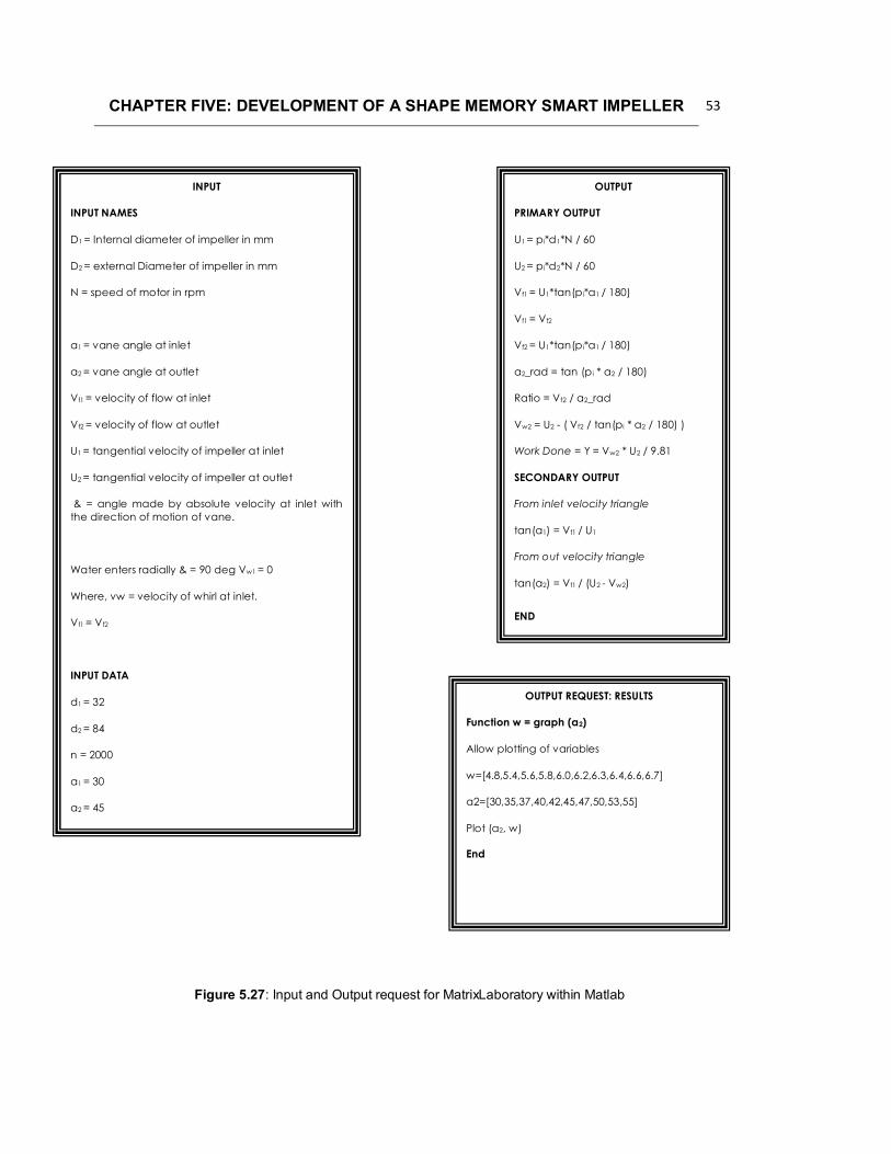
CHAPTER FIVE: DEVELOPMENT OF A SHAPE MEMORY SMART IMPELLER 53
INPUT
INPUT NAMES
D1 = Internal diameter of impeller in mm
D2 = external Diameter of impeller in mm
N = speed of motor in rpm
a1 = vane angle at inlet
a2 = vane angle at outlet
Vf1 = velocity of flow at inlet
Vf2 = velocity of flow at outlet
U1 = tangential velocity of impeller at inlet
U2 = tangential velocity of impeller at outlet
& = angle made by absolute velocity at inlet withthe direction of motion of vane.
Water enters radially & = 90 deg Vw1 = 0
Where, vw = velocity of whirl at inlet.
Vf1 = Vf2
INPUT DATA
d1 = 32
d2 = 84
n = 2000
a1 = 30
a2 = 45
OUTPUT
PRIMARY OUTPUT
U1 = pi*d1*N / 60
U2 = pi*d2*N / 60
Vf1 = U1*tan(p i*a1 / 180)
Vf1 = Vf2
Vf2 = U1*tan(p i*a1 / 180)
a2_rad = tan (p i * a2 / 180)
Ratio = Vf2 / a2_rad
Vw2 = U2 - ( Vf2 / tan(pi * a2 / 180) )
Work Done = Y = Vw2 * U2 / 9.81
SECONDARY OUTPUT
From inlet velocity triangle
tan(a1) = Vf1 / U1
From out velocity triangle
tan(a2) = Vf1 / (U2 - Vw2)
END
OUTPUT REQUEST: RESULTS
Function w = graph (a2)
Allow plotting of variables
w=[4.8,5.4,5.6,5.8,6.0,6.2,6.3,6.4,6.6,6.7]
a2=[30,35,37,40,42,45,47,50,53,55]
Plot (a2, w)
End
Figure 5.27: Input and Output request for MatrixLaboratory within Matlab

CHAPTER FIVE: DEVELOPMENT OF A SHAPE MEMORY SMART IMPELLER 54
Figure 5.28: MATLAB work done versus outlet angle
Region 1 Region 2 Region 3

CHAPTER FIVE: DEVELOPMENT OF A SHAPE MEMORY SMART IMPELLER 55
5.3 Conceptualization of Shape Memory Smart Impeller
From discussions in sections 5.1 and 5.2, it is clear that changing the centrifugal
impeller blade outlet angle increases outlet velocity and in turn the pressure head, as
well as the work done by the impeller on the fluid passing through the system. The
impellers presented above (see Figs. 5.22 – 5.25) were designed to have their outside
blade sections remain identical while the inside blade section changes as the blade
outlet angle is increased. If we now superimpose the 3D solid models of the 4 impellers,
i.e. outlet blade angles from 30, 45, 50, and 55 degrees, we see that the fluid flow
passage (horizontal measurement) is decreased as the outlet blade angle is increased
(see Fig 5.31 below). This is also graphically presented in Fig 5.32. These
measurements were taken using the 3D Solid Modeling software package, SolidWorks,
and were measured from the middle of the inside blade to the center of rotation. For
impeller blade outlet angles 45, 50, and 55 degrees the percentage decrease in the
horizontal measure of fluid flow passage was determined as 1.086, 10.15, and 12.71
respectively.
From the discussion above it is clear that if we consider the entire blade or a section of
it to be constituted of NiTi shape memory alloys and utilizing the shape memory effect it
will be possible to change the blade outlet angle if the temperature of the fluid is
increased above the NiTi specific As transition temperature, thus decreasing the fluid
flow passage and increasing outlet velocity, pressure and work done by the impeller on
the fluid.
Under normal operating conditions, the NiTi SMA will be in its softer martensitic phase.
Any increase in the temperature of the fluid will then lead to the thermo-elastic phase
transformation from martensite to austenite. The NiTi SMA should thus be trained to
transform to the predefined shape of the 55 degree blade outlet angle on heating and
revert back to the 30 degree outlet angle upon cooling (see Fig 5.34).

CHAPTER FIVE: DEVELOPMENT OF A SHAPE MEMORY SMART IMPELLER 56
Figure 5.31: Inlet & Outlet Blade Angle Variations
300450500
550
300 Origin

CHAPTER FIVE: DEVELOPMENT OF A SHAPE MEMORY SMART IMPELLER 57
Figure 5.32: Dimensional Blade Angle Variations
Figure 5.33: Horizontal measurement from Blade Angle Center to Center of Impeller Rotation

CHAPTER FIVE: DEVELOPMENT OF A SHAPE MEMORY SMART IMPELLER 58
Centrifugal Impeller Bladewith NiTi SMA at
temperature below As
transition temperature
Centrifugal Impeller Bladewith NiTi SMA at
temperature above Af
transition temperature
NiTi SMA conforming to300 blade outlet angle(Martensitic Phase)
NiTi SMA conforming to550 blade outlet angle
(Austenitic Phase)
Transformation fromMartensite to Austenitedecreases the fluid flow
passage between blades
Figure 5.34: 1st Conceptual representation of the operating mechanism of the Shape Memory Smart Impeller

CHAPTER FIVE: DEVELOPMENT OF A SHAPE MEMORY SMART IMPELLER 59
5.4 Structural Model
Considering the discussion above and now assuming that the NiTi strip is treated as a
thin beam we find a possible solution to the operating mechanism of the Shape Memory
Smart Impeller (see Fig 5.41 below). At normal operating conditions, i.e. temperatures
below As temperature, the NiTi thin beam assumes the inner shape of the impeller
blade, i.e. 300 inlet angle and 300 outlet angle. Any change in the fluid temperature to
above As and Af will result in the NiTi SMA transforming from its low temperature
martensitic state to the high temperature austenitic state. The latter state would be set
to conform to the blade angle for 300 inlet angle and 550 outlet angle. Furthermore it will
be assumed that the free end (see Fig 5.41) moves within a guide until the final state is
achieved.
NiTi SMA in its low temperature state,i.e. 300 inlet angle and 300 outlet angle
NiTi SMA in its high temperature state,i.e. 300 inlet angle and 550 outlet angle
Transformation strain to be achieved byNiTi SMA
Inner Diameter
Outer Diameter
Inside surfaceof blade
Outlet Angle
Outlet Angle
Inlet AngleFigure 5.41: Operating mechanism of the Shape Memory Smart Impeller

CHAPTER FIVE: DEVELOPMENT OF A SHAPE MEMORY SMART IMPELLER 60
The above assumptions place the solution to this particular in the area of thin beam
theory with an initial curvature. We can then assume end conditions for the particular
problem to be one end (at inlet) of the thin beam is fixed and the other end (at outlet) is
restrained against rotation (see Fig 5.42).
The configuration presented in Fig 5.42 gives the circumferential normal stress as
[46] (5.41)
Where M is the applied bending moment, A is the area of the cross section, e is the
centroidal distance of the specific area’s to the neutral axis, and y and r locate the radial
position of the desired stress from the neutral axis and the center of the curvature (see
Fig 5.43).
Figure 5.42: Idealized model of operating mechanism of the Shape Memory Smart Impeller
M
R
Ѳ
x
y

CHAPTER FIVE: DEVELOPMENT OF A SHAPE MEMORY SMART IMPELLER 61
If we further assume that for our specific beam problem, , then
(5.4.2)
where, d is the width of the beam, I area moment of inertia of the cross section about
the centroidal axis. Since the angular distortion, horizontal and vertical reactions are
zero at the movable end of our beam presented in Fig 5.42, the analytical formulations
for reactions and deformations for the configuration described in Fig 5.42 is given as
[46]
(5.4.3)
(5.4.4)
(5.4.5)
where , and are loading terms to be evaluated for a given situation.
Figure 5.43: Internal loading present in a loaded curved beam

CHAPTER FIVE: DEVELOPMENT OF A SHAPE MEMORY SMART IMPELLER 62
(5.4.6)
(5.4.7)
and
(5.4.8)
(5.4.9)
(5.4.10)
5.5 Constitutive Modeling of NiTi Shape Memory Alloys.
As discussed in section 5.4, the shape memory effect exhibited by shape memory alloys
will be utilized to affect actuation of the Shape Memory Smart Impeller. At normal
operating conditions, i.e. fluid temperatures below austenite start temperature, the NiTi
insert will conform to the shape of a blade with 300 inlet angle and 300 outlet angle. If
the temperature of the water increases to above the austenite start temperature and
continues to rise to austenite finish temperature thus fully transforming martensite to
austenite, the NiTi insert will take the form of a blade with 300 inlet angle and 500 outlet
angle. Considering the configuration presented in Fig 5.42, the transformation strain is
thus equal to the displacement, , of the curved beam. This shape change due to the
temperature increase causes an internal stress to be developed in the NiTi insert equal
to the circumferential stress, , discussed in section 5.4.
Constitutive models developed for shape memory alloys have followed different
approaches [ ]. In this study however, the Brinson model [ ] will be used. This model
uses constant material functions and offers the advantage of capturing the thermo-

CHAPTER FIVE: DEVELOPMENT OF A SHAPE MEMORY SMART IMPELLER 63
mechanical behavior of SMA’s at any temperature and includes in its expression
quantifyable engineering quantities and material properties. Based on the energy
balance law, the constitutive relation for SMA’s according to the Brinson model [45 ] is
given as:
(5.5.1)
where the quantities in the initial state is given by the suffix 0, and the actual quantities
without the suffix. The terms or quantities in equ. 5.5.1 is given as follows:
is the Young’s modulus, and is given in terms of a linear function of the
martensite phase as with EA and EM representing the
100% austenite and 100% martensite Young’s Moduli respectively.
represent the martensite phase fraction present in the material and is
composed of two types, i.e. thermally transformed and stress induced, given as
.
represent a so called transformation tensor, related to Young’s Modulus, and
is given in the form . is the maximum transformation
strain and for this particular situation assumed to be related to the displacement,
, of the curved beam.
The final term in equ 5.5.1, is related to the thermal strain generated
in the SMA due to the rise in temperature and is equivalent to the thermal
expansion of the SMA.
If we now assume that when the material is in its initial state it is free from stress, in a
fully twinned mareinsitic state, and that the elastic strain components are negligible
compared to the transformation strain, then equ 5.5.1 is dependant only on thermal and
transformation strains and is reduced to

CHAPTER FIVE: DEVELOPMENT OF A SHAPE MEMORY SMART IMPELLER 64
(5.5.2)
The mechanism of actuation for our smart impeller is driven purely by thermal changes,
i.e. increases in temperature from As to Af will transform the twinned martensite to
austenite, thus causing the shape change from a 300 inlet angle and 300 outlet angle to
300 inlet angle and 550 outlet angle. In the reverse transformation, i.e. a decrease in
temperature from Ms to Mf, will transform the austenite back to twinned martensite and
the SMA reverts back to the 300 inlet angle and 300 outlet angle.
If we assume that the transformation is not dependant on stress, Brinson [45 ] proposed
the following relations associated and for equ 5.5.2.
For the conversion to Austenite
(5.5.3)
where and holds for
For the conversion to Martensite
(5.5.4)
where and holds for and , else
The total transformation displacement [ ] is further given as
for transformation to austenite (5.5.5)
and
for transformation to martensite (5.5.6)
with
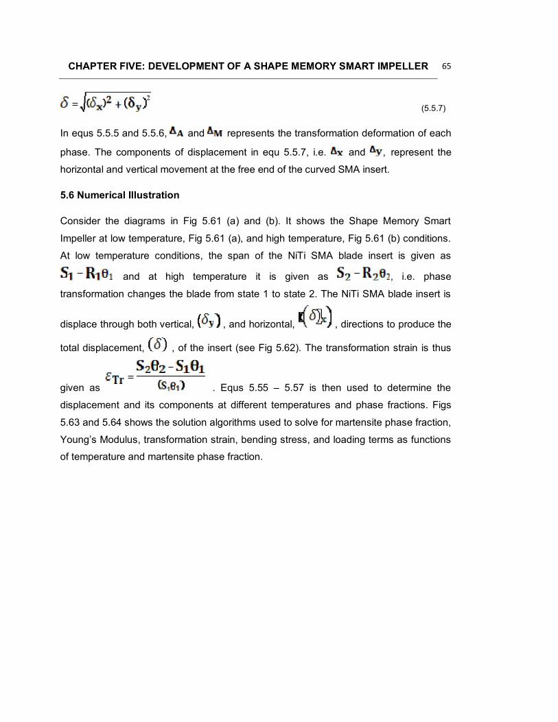
CHAPTER FIVE: DEVELOPMENT OF A SHAPE MEMORY SMART IMPELLER 65
(5.5.7)
In equs 5.5.5 and 5.5.6, and represents the transformation deformation of each
phase. The components of displacement in equ 5.5.7, i.e. and , represent the
horizontal and vertical movement at the free end of the curved SMA insert.
5.6 Numerical Illustration
Consider the diagrams in Fig 5.61 (a) and (b). It shows the Shape Memory Smart
Impeller at low temperature, Fig 5.61 (a), and high temperature, Fig 5.61 (b) conditions.
At low temperature conditions, the span of the NiTi SMA blade insert is given as
and at high temperature it is given as , i.e. phase
transformation changes the blade from state 1 to state 2. The NiTi SMA blade insert is
displace through both vertical, , and horizontal, , directions to produce the
total displacement, , of the insert (see Fig 5.62). The transformation strain is thus
given as . Equs 5.55 – 5.57 is then used to determine the
displacement and its components at different temperatures and phase fractions. Figs
5.63 and 5.64 shows the solution algorithms used to solve for martensite phase fraction,
Young’s Modulus, transformation strain, bending stress, and loading terms as functions
of temperature and martensite phase fraction.

CHAPTER FIVE: DEVELOPMENT OF A SHAPE MEMORY SMART IMPELLER 66
(a) (b)
NiTi SMABlade Insert
Low Temperature condition with NiTiSMA Blade Insert conforming to 300
inlet angle and 300 outlet angle
High Temperature condition with NiTiSMA Blade Insert conforming to 300
inlet angle and 550 outlet angle
Figure 5.61: Idealized model of the Shape Memory Smart Impeller with (a) showing low temperatureconfiguration and (b) showing high temperature configuration.
Y
XFigure 5.62: Illustration showing total displacement, the horizontal component of displacement and the
vertical component of displacement.
Ѳ1R1 Ѳ2R2

CHAPTER FIVE: DEVELOPMENT OF A SHAPE MEMORY SMART IMPELLER 67
For transformation from 300inlet angle and 300outlet angle to
300inlet angle and 550outlet angle
1. Assume Temperatures between As and Af
2. Calculate
3. determine at different temperatures between As and Af.
4. determine Young’s Modulus =
5. determine transformation strain = and transformation stress =
6. determine and
7. determine as function of and
8. determine M using
9 determine and and as function of and
For transformation from 300inlet angle and 550outlet angle to
300inlet angle and 500outlet angle
1. Assume Temperatures between Ms and Mf
2. Calculate
3. determine at different temperatures between Ms andMf.
4. determine Young’s Modulus =
5. determine transformation strain = and transformation stress =
6. . determine and
7. determine as function of and
8. determine M using
9 determine and and as function of and
Figure 5.63: Solution algorithm used for heating condition..
Figure 5.64: Solution algorithm used for cooling condition..

CHAPTER FIVE: DEVELOPMENT OF A SHAPE MEMORY SMART IMPELLER 68
All constants used in the algorithm have been defined previously [45 ] and will given in
Table 5.61.
Table 5.61: Constants used in the Solution Algorithms
Symbol Description Value
As Austenite Start Temperature 44.650C
Af Austenite Finish Temperature 52.040C
Ms Martensite Start Temperature 39.630C
Mf Martensite Finish Temperature 32.540C
EM Martensite Young’s Modulus 34GPa
EM Austenite Young’s Modulus 89GPa
NiTi Thermal Expansion Coefficient 10e-5/0C
Density of NiTi SMA 6450 kg/m3
T0 Reference Temperature 400C
DI Diameter of Impeller 84mm
DE Diameter of Eye 32mm
R1 Radius of SMA Blade insert at low temperature state 45.7mm
Ѳ1Angle forming Span of SMA Blade insert at low
temperature state44.1650 = 0.77082rad
Ѳ2Angle forming Span of SMA Blade insert at high
temperature state30.5240 = 0.53274rad
R2Radius of SMA Blade insert at high temperature
state63.1mm
A SMA Insert Area 1.5e-3 x 5e-3 m2
I SMA Insert Second Moment of Area (1.5e-3)3 x (5e-3) / 12m3
The results of the solution is provided in the tables below, i.e. Table 5.62 – 5.64 shows
results for heating and Table 5.65 – 5.67 shows results for cooling. Fig 5.65 graphically
shows the martensitic phase fraction for both heating and cooling. Fig 5.66 graphically
shows the displacements with its components for both heating and cooling.
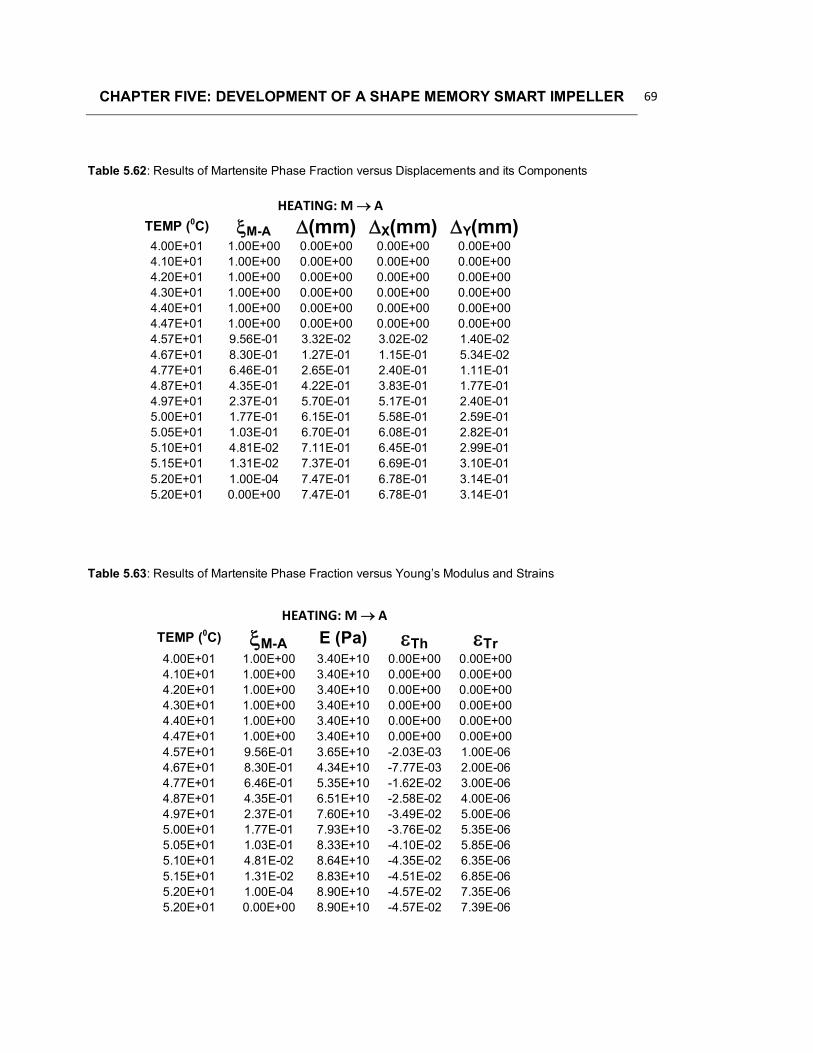
CHAPTER FIVE: DEVELOPMENT OF A SHAPE MEMORY SMART IMPELLER 69
HEATING: M ATEMP (0C) M-A (mm) X(mm) Y(mm)4.00E+01 1.00E+00 0.00E+00 0.00E+00 0.00E+004.10E+01 1.00E+00 0.00E+00 0.00E+00 0.00E+004.20E+01 1.00E+00 0.00E+00 0.00E+00 0.00E+004.30E+01 1.00E+00 0.00E+00 0.00E+00 0.00E+004.40E+01 1.00E+00 0.00E+00 0.00E+00 0.00E+004.47E+01 1.00E+00 0.00E+00 0.00E+00 0.00E+004.57E+01 9.56E-01 3.32E-02 3.02E-02 1.40E-024.67E+01 8.30E-01 1.27E-01 1.15E-01 5.34E-024.77E+01 6.46E-01 2.65E-01 2.40E-01 1.11E-014.87E+01 4.35E-01 4.22E-01 3.83E-01 1.77E-014.97E+01 2.37E-01 5.70E-01 5.17E-01 2.40E-015.00E+01 1.77E-01 6.15E-01 5.58E-01 2.59E-015.05E+01 1.03E-01 6.70E-01 6.08E-01 2.82E-015.10E+01 4.81E-02 7.11E-01 6.45E-01 2.99E-015.15E+01 1.31E-02 7.37E-01 6.69E-01 3.10E-015.20E+01 1.00E-04 7.47E-01 6.78E-01 3.14E-015.20E+01 0.00E+00 7.47E-01 6.78E-01 3.14E-01
HEATING: M ATEMP (0C) M-A E (Pa) Th Tr4.00E+01 1.00E+00 3.40E+10 0.00E+00 0.00E+004.10E+01 1.00E+00 3.40E+10 0.00E+00 0.00E+004.20E+01 1.00E+00 3.40E+10 0.00E+00 0.00E+004.30E+01 1.00E+00 3.40E+10 0.00E+00 0.00E+004.40E+01 1.00E+00 3.40E+10 0.00E+00 0.00E+004.47E+01 1.00E+00 3.40E+10 0.00E+00 0.00E+004.57E+01 9.56E-01 3.65E+10 -2.03E-03 1.00E-064.67E+01 8.30E-01 4.34E+10 -7.77E-03 2.00E-064.77E+01 6.46E-01 5.35E+10 -1.62E-02 3.00E-064.87E+01 4.35E-01 6.51E+10 -2.58E-02 4.00E-064.97E+01 2.37E-01 7.60E+10 -3.49E-02 5.00E-065.00E+01 1.77E-01 7.93E+10 -3.76E-02 5.35E-065.05E+01 1.03E-01 8.33E+10 -4.10E-02 5.85E-065.10E+01 4.81E-02 8.64E+10 -4.35E-02 6.35E-065.15E+01 1.31E-02 8.83E+10 -4.51E-02 6.85E-065.20E+01 1.00E-04 8.90E+10 -4.57E-02 7.35E-065.20E+01 0.00E+00 8.90E+10 -4.57E-02 7.39E-06
Table 5.62: Results of Martensite Phase Fraction versus Displacements and its Components
Table 5.63: Results of Martensite Phase Fraction versus Young’s Modulus and Strains

CHAPTER FIVE: DEVELOPMENT OF A SHAPE MEMORY SMART IMPELLER 70
HEATING: M ATEMP (0C) M-A E (Pa) Th(Pa) Tr(Pa) (Pa)4.00E+01 1.00E+00 3.40E+10 0.00E+00 0.00E+00 0.00E+004.10E+01 1.00E+00 3.40E+10 0.00E+00 0.00E+00 0.00E+004.20E+01 1.00E+00 3.40E+10 0.00E+00 0.00E+00 0.00E+004.30E+01 1.00E+00 3.40E+10 0.00E+00 0.00E+00 0.00E+004.40E+01 1.00E+00 3.40E+10 0.00E+00 0.00E+00 0.00E+004.47E+01 1.00E+00 3.40E+10 0.00E+00 0.00E+00 0.00E+004.57E+01 9.56E-01 3.65E+10 -7.41E+07 3.65E+04 -7.41E+074.67E+01 8.30E-01 4.34E+10 -3.37E+08 8.67E+04 -3.37E+084.77E+01 6.46E-01 5.35E+10 -8.66E+08 1.61E+05 -8.66E+084.87E+01 4.35E-01 6.51E+10 -1.68E+09 2.60E+05 -1.68E+094.97E+01 2.37E-01 7.60E+10 -2.65E+09 3.80E+05 -2.65E+095.00E+01 1.77E-01 7.93E+10 -2.98E+09 4.24E+05 -2.98E+095.05E+01 1.03E-01 8.33E+10 -3.41E+09 4.87E+05 -3.41E+095.10E+01 4.81E-02 8.64E+10 -3.76E+09 5.48E+05 -3.76E+095.15E+01 1.31E-02 8.83E+10 -3.98E+09 6.05E+05 -3.98E+095.20E+01 1.00E-04 8.90E+10 -4.07E+09 6.54E+05 -4.07E+095.20E+01 0.00E+00 8.90E+10 -4.07E+09 6.58E+05 -4.07E+09
COOLING: AMTEMP (0C) A-M (mm) X(mm) Y(mm)5.20E+01 0.00E+00 7.47E-01 6.78E-01 3.14E-014.50E+01 0.00E+00 7.47E-01 6.78E-01 3.14E-014.00E+01 0.00E+00 7.47E-01 6.78E-01 3.14E-013.96E+01 0.00E+00 7.47E-01 6.78E-01 3.14E-013.86E+01 4.83E-02 7.11E-01 6.45E-01 2.99E-013.76E+01 1.84E-01 6.10E-01 5.53E-01 2.56E-013.66E+01 3.80E-01 4.63E-01 4.20E-01 1.95E-013.56E+01 6.00E-01 2.99E-01 2.71E-01 1.26E-013.46E+01 8.00E-01 1.49E-01 1.36E-01 6.28E-023.40E+01 8.99E-01 7.54E-02 6.85E-02 3.17E-023.35E+01 9.55E-01 3.36E-02 3.05E-02 1.41E-023.30E+01 9.89E-01 8.22E-03 7.46E-03 3.45E-033.28E+01 9.97E-01 2.24E-03 2.03E-03 9.42E-043.25E+01 1.00E+00 0.00E+00 0.00E+00 0.00E+003.00E+01 1.00E+00 0.00E+00 0.00E+00 0.00E+002.90E+01 1.00E+00 0.00E+00 0.00E+00 0.00E+002.50E+01 1.00E+00 0.00E+00 0.00E+00 0.00E+00
Table 5.64: Results of Martensite Phase Fraction versus Young’s Modulus and Stresses
Table 5.65: Results of Martensite Phase Fraction versus Displacements and its Components

CHAPTER FIVE: DEVELOPMENT OF A SHAPE MEMORY SMART IMPELLER 71
COOLING: AMTEMP (0C) M-A E (Pa) Th Tr5.20E+01 0.00E+00 8.90E+10 -4.57E-02 0.00E+004.50E+01 0.00E+00 8.90E+10 -4.57E-02 -7.04E-064.00E+01 0.00E+00 8.90E+10 -4.57E-02 -1.20E-053.96E+01 0.00E+00 8.90E+10 -4.57E-02 -1.24E-053.86E+01 4.83E-02 8.63E+10 -4.35E-02 -1.34E-053.76E+01 1.84E-01 7.89E+10 -3.73E-02 -1.44E-053.66E+01 3.80E-01 6.81E+10 -2.83E-02 -1.54E-053.56E+01 6.00E-01 5.60E+10 -1.83E-02 -1.64E-053.46E+01 8.00E-01 4.50E+10 -9.14E-03 -1.74E-053.40E+01 8.99E-01 3.96E+10 -4.62E-03 -1.80E-053.35E+01 9.55E-01 3.65E+10 -2.06E-03 -1.85E-053.30E+01 9.89E-01 3.46E+10 -5.03E-04 -1.90E-053.28E+01 9.97E-01 3.42E+10 -1.37E-04 -1.92E-053.25E+01 1.00E+00 3.40E+10 0.00E+00 0.00E+003.00E+01 1.00E+00 3.40E+10 0.00E+00 0.00E+002.90E+01 1.00E+00 3.40E+10 0.00E+00 0.00E+002.50E+01 1.00E+00 3.40E+10 0.00E+00 0.00E+00
COOLING: AMTEMP (0C) M-A E (Pa) Th(Pa) Tr(Pa) (Pa)5.20E+01 0.00E+00 8.90E+10 -4.07E+09 0.00E+00 -4.07E+094.50E+01 0.00E+00 8.90E+10 -4.07E+09 -6.27E+05 -4.07E+094.00E+01 0.00E+00 8.90E+10 -4.07E+09 -1.07E+06 -4.07E+093.96E+01 0.00E+00 8.90E+10 -4.07E+09 -1.10E+06 -4.07E+093.86E+01 4.83E-02 8.63E+10 -3.76E+09 -1.16E+06 -3.76E+093.76E+01 1.84E-01 7.89E+10 -2.94E+09 -1.14E+06 -2.94E+093.66E+01 3.80E-01 6.81E+10 -1.93E+09 -1.05E+06 -1.93E+093.56E+01 6.00E-01 5.60E+10 -1.02E+09 -9.19E+05 -1.02E+093.46E+01 8.00E-01 4.50E+10 -4.11E+08 -7.83E+05 -4.12E+083.40E+01 8.99E-01 3.96E+10 -1.83E+08 -7.14E+05 -1.83E+083.35E+01 9.55E-01 3.65E+10 -7.50E+07 -6.76E+05 -7.57E+073.30E+01 9.89E-01 3.46E+10 -1.74E+07 -6.59E+05 -1.81E+073.28E+01 9.97E-01 3.42E+10 -4.68E+06 -6.57E+05 -5.34E+063.25E+01 1.00E+00 3.40E+10 0.00E+00 0.00E+00 0.00E+003.00E+01 1.00E+00 3.40E+10 0.00E+00 0.00E+00 0.00E+002.90E+01 1.00E+00 3.40E+10 0.00E+00 0.00E+00 0.00E+002.50E+01 1.00E+00 3.40E+10 0.00E+00 0.00E+00 0.00E+00
Table 5.66: Results of Martensite Phase Fraction versus Young’s Modulus and Strains
Table 5.67: Results of Martensite Phase Fraction versus Young’s Modulus and Stresses

CHAPTER FIVE: DEVELOPMENT OF A SHAPE MEMORY SMART IMPELLER 72
Figure 5.65: Martensite Phase Fraction for Heating and Cooling versus Temperature
Figure 5.66: Total Displacements and its components versus Temperature
A-M M-A
HEATINGPATHS
COOLINGPATHS

CHAPTER FIVE: DEVELOPMENT OF A SHAPE MEMORY SMART IMPELLER 73
Figure 5.67: Transformation Strain versus Temperature
Figure 5.68: Total Internal Stress versus Temperature

CHAPTER FIVE: DEVELOPMENT OF A SHAPE MEMORY SMART IMPELLER 74
From the 3D solid modeling software package, SolidWorks, the maximum total
displacement, ,was measured as 0.747mm with its components, i.e. vertical, ,and
horizontal, , being 0.678mm and 0.314mm respectively. Fig 5.66 graphically shows
these values as they change with temperature for both heating and cooling.
The maximum transformation strain, i.e. , was determined at
4.57e-2 compressive, and Fig 5.67 shows how it transforms for both heating and
cooling. The maximum total circumferential stress was determined at 4.09GPa –
compressive and is shown graphically in Fig 5.68 for both heating and cooling cycles.
The internal moment due to the phase transformation was determined as 7.63Nm while
the loading terms of Equ 5.43 – 5.45, i.e. , and , were determined
as 128.837N, 11.5026N, and 11.5026N respectively.
5.7 Discussion of Results
The method shown above shows the feasibility of using the approach to solve for the
displacements, i.e. total, vertical and horizontal, at all instances of temperature and
martensite phase fraction. It thus indicates that a Shape Memory Smart Impeller is
conceptualized. The displacements, although small, changes the outlet angle of the
blade from 300 to 550, thus theoretically increasing the velocity at the outlet and
increasing the head of the centrifugal impeller. It should be noted though that for this
specific situation, an optimum anlge of attack of 43.30 would produce the optimum work
done and efficiency as described in section 5.2. This indecates that the shape memory
insert be trained to conform to this outlet angle and thus actuate within region 2 of Fig.
5.28.

CHAPTER FIVE: DEVELOPMENT OF A SHAPE MEMORY SMART IMPELLER 75
The moment at the free end is small and under normal operating conditions the force of
flow would overcome this moment thus not affecting the transformation. The internal
stress is high and further investigation into the shape and geometry of the blade and or
insert should be conducted to improve the internal stress.

CHAPTER SIX: EFD ANALYSES 76
CHAPTER SIX
EFD ANALYSES
6.1 Background to ENGINEERING FLUID DYNAMICS (EFD)
Computers these days play a major role in design of aerodynamic and hydro-dynamic
structures. CAD embedded fluid flow simulation software have redefined the design process
by allowing for effective design optimization with little cost and in less time.
EFD.Lab is a full-featured general purpose CAD-embedded finite volume fluid flow and heat
transfer simulation tool that encompasses the following features:
Rectangular adaptive meshing (with manual or automatic refinement).
Partial cells technology to accurately simulate near wall boundary conditions.
Laminar, transitional and turbulent flow regimes, all automatically generated and within
the same model.
Turbulent flow modelled using the Favre-Averaged Navier Stokes equation.
Automatic convergence control
EFD was developed by Flomerics, who are world-leading developers of engineering
simulation software and services for analysis of fluid flow, heat transfer and electromagnetic

CHAPTER SIX: EFD ANALYSES 77
radiation. Flomerics’ software is designed to be embedded deeply into the design process
and used by mainstream design engineers, not just by analysis specialists.
6.1.1 Rectangular adaptive meshing
EFD calculations are performed in a rectangular parallelepiped-shaped computational
domain whose boundaries are orthogonal to the axes of the Cartesian Global coordinate
system. A computational mesh splits the computational domain with a set of planes
orthogonal to the Cartesian Global Coordinate System’s axes to form rectangular
parallelepipeds called cells. The resulting mesh consists of cells of the following three types
(shown in figure 6.1):
Fluid cells are the cells located entirely in the fluid
Solid cells are the cells located entirely in the solid
Partial cells are the cells which are partly in the solid and partly in the fluid. For each
partial cell the following information is kept: coordinates of intersections of the cell
edges with the solid surface and normal to the solid surface within the cell.
Figure 6.1: Mesh cell types.

CHAPTER SIX: EFD ANALYSES 78
The mesh is constructed in the following steps:
Construction of basic mesh taking into account the control planes and respective
values of cell number and cell size ratios.
Resolving of the interface between substances, including refinement of the basic
mesh at the solid/fluid and solid/solid boundaries to resolve the relatively small solid
features and solid/solid interface, tolerance and curvature refinement of the mesh at a
solid/fluid, solid/porous and fluid/porous boundaries to resolve the interface curvature.
Narrow channels refinement, which is the refinement of the mesh in narrow channels
taking into account the respective user-specified settings.
Refinement of all fluid, and or solid, and or partial mesh cells up to the user-specified
level.
Mesh conservation. i.e. a set of control procedures, including check for the difference
in area of cell facets common for the adjacent cells of different levels.
6.2 Simulation algorithm for Engineering Fluid Dynamics
Water flows through a centrifugal pump having a rotating impeller (see below). This pump
has a stationary axial inlet (an eye), a pipe section with a central body of circular arc contour,
which turns the flow by 90 degrees from the axial direction. At the inlet's exit the radial water
flow is sucked by a rotating impeller, which has seven untwisted constant-thickness
backswept blades. Each blade is cambered from 30 degrees at the impeller inlet of 16 mm
radius to range of 0 to 90 degrees at the impeller exit of 42 mm radius, both with respect to
the radial direction. While keeping all configurations the same, only the impeller outlet angle
was increase for each in impeller by 5 degree. The inlet angle for all impeller was 30
degrees. These blades are confined between the impeller shrouding disks rotating with the
same (as the blades) angular speed of 2000 rpm

CHAPTER SIX: EFD ANALYSES 79
N=2000rpm
Figure 6.12: Basic construction of impeller
Figure 6.13: Centrifugal pumps with rotating impeller.
To complete the problem statement, let us specify the following inlet and outlet boundary
conditions: inlet water of 0.3 m3s-1 volume flow rate having uniform velocity profile with
vectors parallel to the pump's axis; at the radial-directed outlet a static pressure of 1
atmosphere is specified.

CHAPTER SIX: EFD ANALYSES 80
Table 6.2: Project definition table
.
Figure 6.21: Creating a new wizard
6.2.1Project Definition: A new project was created using the wizard
Water
5

CHAPTER SIX: EFD ANALYSES 81
Figure 6.22: Creating analysis type
Figure 6.23: Creating physical features

CHAPTER SIX: EFD ANALYSES 82
Figure: 6.24: Creating wall conditions
Figure 6.25: Geometry Resolution. The resolution was set to level 5

CHAPTER SIX: EFD ANALYSES 83
Inner face
6.3 Boundary Conditions
6.31 Inlet boundary condition.
Inlet Volume Flow: Volume flow rate of 0.3 m^3/s (uniform velocity profile) normal to
the inner face of the Cover in the absolute frame of reference (the Relative to rotating
frame option is disabled);
The inlet boundary is specified as shown below
6.32 Outlet boundary condition:
Outlet Environment Pressure: Default value (101325 Pa) for the Environment pressure
(in the absolute frame of reference - the Pressure potential is disabled) at the radial
outlet face.

CHAPTER SIX: EFD ANALYSES 84
Figure: 6.32: Outlet boundary condition
6.4 Specifying Stationary Walls
The stator condition at the corresponding walls of the pump’s cover was specify
1. Select the inner cover’s faces except for the outlet and inlet faces.
2. Click Flow Analysis, Insert, Boundary Condition.
3. Click Wall, keep the default Real Wall condition type and go to the MovingWall Settings tab.
4. On the Moving Wall Settings tab, click Stator.
5. Click OK and rename the new Real Wal l1 condition to Stator Walls.
Outlet Boundarycondition

CHAPTER SIX: EFD ANALYSES 85
Figure: 6.41: Selecting stationary walls
6.5 Impeller efficiency
Engineers dealing with pump equipment are interested in the pump efficiency. For the
pump under consideration the efficiency ( ) can be calculated in the following way
where Pinlet is the static pressure at the pump’s inlet, Poutlet is the bulk-average static
pressures at the impeller’s outlet (Pa), Q is the volume flow rate (m3/s), Ω is the impeller
rotation angular velocity (rad/s), and M is the impeller torque (N·m). To obtain Poutlet, an
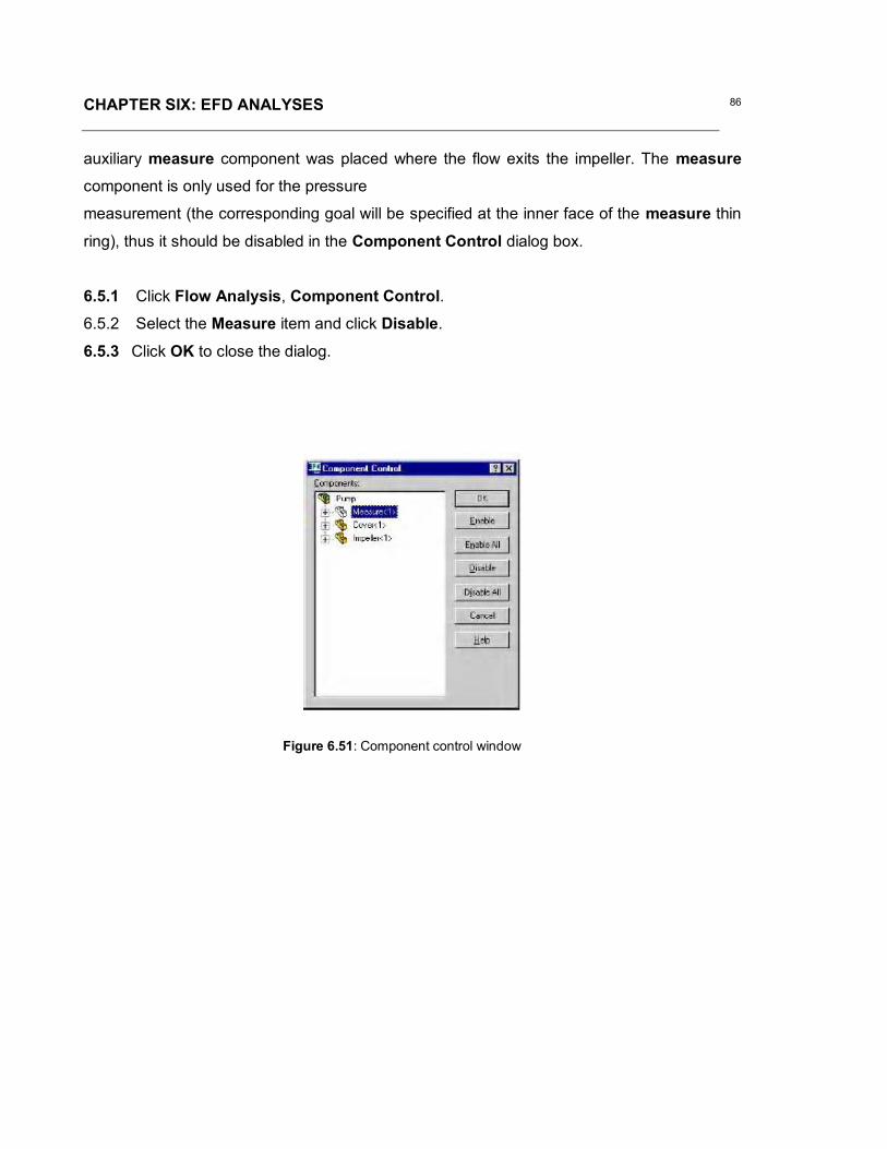
CHAPTER SIX: EFD ANALYSES 86
Figure 6.51: Component control window
auxiliary measure component was placed where the flow exits the impeller. The measurecomponent is only used for the pressure
measurement (the corresponding goal will be specified at the inner face of the measure thin
ring), thus it should be disabled in the Component Control dialog box.
6.5.1 Click Flow Analysis, Component Control.6.5.2 Select the Measure item and click Disable.
6.5.3 Click OK to close the dialog.

CHAPTER SIX: EFD ANALYSES 87
Figure 6.61: Creating surface Goals
6.6 Specifying project goals
First, since the pressure and volume flow rate boundary condition are specified, it makes
sense to set the mass flow rate surface goal at the pump’s inlet and outlet to inspect the
mass balance as an additional criterion for converging the calculation.
Specifyinggoals

CHAPTER SIX: EFD ANALYSES 88
Figure 6.62: Naming Goals' tree
Table 6.6: Specifying project goals

CHAPTER SIX: EFD ANALYSES 89
Figure 6.71: Creating equation Goals
6.7 Specifying equation goals
To avoid manual selecting of all impeller’s faces in contact with water (more than 150)
we will calculate impeller torque as the difference between the global torque
(calculated over all faces in contact with water) and the stator torque (calculated over
the stator faces in contact with water)

CHAPTER SIX: EFD ANALYSES 90
Table 6.7: Specifying equation goals
Figure 6.72: Naming equations' tree
Save the model and run the calculations

CHAPTER SIX: EFD ANALYSES 91
Figure 6.81: Pressure plot
6.8 Results.
The velocity vectors and static pressure distribution are shown below. To display vectors
in the rotating reference frame, in the View Settings open the Parameter List dialog box
and select Velocity RRF parameter. Then select the Velocity RRF parameter under the
Vectors tab of the View Settings dialog box.

CHAPTER SEVEN: RESULTS & DISCUSSION OF CFD ANALYSES 92
CHAPTER SEVEN
RESULTS & DISCUSSION OF CFDANALYSES
7.1 Results of Engineering Fluid Dynamics
If we consider the situation described in section 5.2, Chapter 5 and considering
the inputs described in Chapter 6 we construct 6 solid models of our impeller,
each having an inlet blade angle 300 but outlet angles varying from 300 to 550
with increments of 50. It is clear that the efficiency of the impeller drops drastically
from 30 degrees inlet and 30 degrees outlet, but increases gradually as the outlet
angle increase from this point. The graph also shows a characteristic optimum
increase up to 45 degrees outlet where it starts to flatten out. This will allow us to
have an angle of attack of 15 degrees from an inlet angle of 30 degrees.

CHAPTER SEVEN: RESULTS & DISCUSSION OF CFD ANALYSES 93
Efficiency Vs Angle of Attack
0
10
20
30
40
50
60
30 35 40 45 50 55
Angle of Attack
Effic
ienc
y
Efficiency Vs Angle of Attack
0
10
20
30
40
50
60
30 35 40 42 44 45 46 48 50 55
Angle of Attack
Effic
ienc
y
Figure 7.31: efficiency versus angle of attack in steps of 5 degrees
Figure 7.32: Detail investigation of efficiency versus angle of attack
A Detail investigation reveals that there is a jump from 42 degrees to 45 degrees.
Secondly there is a decrease from 45degrees to 46 before increasing slowing
onward.

CHAPTER SEVEN: RESULTS & DISCUSSION OF CFD ANALYSES 94
Torque on impeller vs Angle of attack
3000
3050
3100
3150
3200
3250
3300
3350
3400
3450
3500
3550
35 40 42 44 45 46 48 50 55
Angle of Attack
Torq
ue o
n im
pelle
r
Torque Vs Outlet angle
31753180
318531903195
32003205
32103215
41.5 42 42.5
Outlet angle (degrees)
Torq
ue (
Nm)
Figure 7.33: Detail investigation of impeller torque versus angle of attack.
Figure 7.34: Torque vs. outlet angle
Investigating the torque on the system, it was revealed that despite an increase
in the efficiency from 40 degrees to 42 degrees at the outlet, there is surprisingly
a decrease in the torque in this section. See figure 7.33 below.
A closer look at the torque alone on both sides of 42 degrees (where there is a
drop) confirms our V-shape. (See Figure 7.34)

CHAPTER SEVEN: RESULTS & DISCUSSION OF CFD ANALYSES 95
Torque Vs Outlet angle
3120
3140
3160
3180
3200
3220
3240
3260
3280
3300
3320
40 41.5 42 42.5 44
Outlet angle (Degrees)
Torq
ue (N
m)
Figure 7.35: Polynomial gutter curve
.
A trend in the between 40 degrees and 44 degrees confirms and reveals a
polynomial gutter curve with the lowest torque still at 42 degrees. See figure 7.35
7.2 Investigation of results.
i) Passage area
Looking at the blade to blade orientation, (see figure below) and investigating the
blade passage area ABCD (see figure below) and the passage outlet length for
variable angle of attack, the following results were obtained.

CHAPTER SEVEN: RESULTS & DISCUSSION OF CFD ANALYSES 96
Inlet Passage (constant)
Outlet Passage (Variable)Two blades
Passage ABCD
A
D
B
C
Figure 7.36: Passage area obtained from Blade to Blade setup
Figure 7.37: Detail investigation on passage area versus outlet angle.
The passage areas demonstrate continues decrease with increase in outlet
angle. See figure 7.37 below.
AREA VS OUTLET ANGLE
546
548
550
552
554
556
558
560
562
35 40 42 44 45 46 48 50 55
OUTLET ANGLE
AREA

CHAPTER SEVEN: RESULTS & DISCUSSION OF CFD ANALYSES 97
Figure 7.38: Detail investigation on outlet passage length versus outlet angle.
ii) Passage length
Quiet amazingly, the passage length is erratic, but with outlet angle 42 degrees
at the minimum and 45 degrees at the maximum. See figure 7.38 below
Passage Length vs outlet angle
29.4
29.45
29.5
29.55
29.6
29.65
29.7
29.75
29.8
35 40 42 44 45 46 48 50 55
Outlet Angle
Pass
age
Leng
th
7.3 Discussion of Results.
From analytical algorithm and EFD comparison, it was evident that the best angle
of attack is 12 degree at the outlet angle with respect to the inlet angle.
From EFD results, it is palpable that, by increasing the angle of attack from 35
degree to 45 degree at the outlet there will be huge increase in flow rate by
63.47%
There is also a slight decrease in the in the impeller Torque from 35 degrees to
42 degrees by 0.72%.

CHAPTER SEVEN: RESULTS & DISCUSSION OF CFD ANALYSES 98
602 NT
It is economically feasible to work at an outlet angle of 42 degrees due to
increase in efficiency of 62.1% and a drop in torque of 0.72% by varying the
outlet angle from 35 degrees to 42 degree.
Looking at the particle inspection for each angle of attack in EFD, it was revealed
that there were fewer eddies at the outlet angle of 42 degrees as opposed to the
other outlet angles.
According to Bansal [41] more eddies indicate
More friction,
Less flow
Lower fluid velocity
Lower efficiency
The increase in efficiency with increase in angle of attack was expected, but with
corresponding increase in Torque on the impeller since the power of the system
remains constant.
P = [43]
P=Power transmitted in watt
N=Rotational speed of impeller in rev/min
T=Torque on impeller in N.m

CHAPTER SEVEN: RESULTS & DISCUSSION OF CFD ANALYSES 99
T
QPP inletoutlet
..
From:
= efficiency
Q = Flow rate (constant)
Poutlet = Pressure at outlet
Pinlet = Pressure at inlet (constant)
=Angular Velocity in rads/sec (constant)
From Pressure = Force/Area, it means that, if the passage of the outlet is
increase (as seen in figure above at outlet angle of between 42 and 45 degrees)
then there will be a lower pressure at the outlet, but with the constant inlet
passage it will bring our equation above to:
inletoutlet PPT
With Pinlet constant, the efficiency increase overrides the Poutlet at its minimum
thereby resulting in the drop in torque.

CHAPTER EIGHT: CONCLUSION AND RECOMMENDATION 100
CHAPTER EIGHT
CONCLUSION
8.1 Conclusion
This study successfully conceptualised a Shape Memory Smart Centrifugal
Impeller that will increase fluid flow rate through a given system if the fluid
temperature increases above a given transition temperature (see section 5.2 of
Chapter 5). The proposed smart pumping system, makes it possible to pump
more fluid through a given system with the same power and with a decrease in
impeller shaft torque (see Chapter 7). Results also show that it is possible to do
more work (pump more fluid) with less power using a smart pumping system (see
Chapter 7).
A demonstration centrifugal pumping system, i.e. FM21, in the Department of
Mechanical Engineering of the Cape Peninsula University of Technology was
used to create an understanding of such systems and analytical solutions for the
system was described (see Chapters 3 and 5). The optimum conditions for a
pumping system based on FM21 was determined by using specific inputs and
varying impeller outlet angles from 300 to 550. The study successfully identified
Optimum impeller blade inlet angle with corresponding outlet angle and
efficiency

CHAPTER EIGHT: CONCLUSION AND RECOMMENDATION 101
Optimum impeller blade inlet angle with corresponding outlet angle and
impeller outlet velocity
Optimum impeller blade inlet angle with corresponding outlet angle and
fluid flow rate through the impeller
Optimum impeller blade inlet angle with corresponding outlet angle and
impeller shaft torque
Optimum impeller blade inlet angle with corresponding outlet angle with
least eddy formation in the impeller system.
The conceptualization of the Shape Memory Smart Impeller using NiTi Shape
Memory Alloys was achieved using Curved Beam Theory with the specific case
of a curved beam with end conditions for the particular problem to be one end (at
inlet) fixed and the other end (at outlet) is restrained against rotation (see Section
5.4). Based on the energy balance law, the constitutive relation for SMA’s
according to the Brinson model was used to determine forward transformation,
i.e. Martensite to Austenite, and the reverse transformation, i.e. Austenite to
Martensite. These transformations describe the mechanism of operation of the
Shape Memory Smart Impeller. Analytical solutions show the feasibility of using
the approach to solve for the displacements, i.e. total, vertical and horizontal, at
all instances of temperature and martensite phase fraction. The displacements,
although small, changes the outlet angle of the blade from 300 to 550, thus
theoretically increasing the velocity at the outlet and increasing the head of the
centrifugal impeller.
Engineering Fluid Dynamics (EFD.Lab), a full-featured general purpose CAD-
embedded finite volume fluid flow and heat transfer simulation tool was used to
perform computational fluid dynamics analyses. The results confirmed the
optimum conditions of the specific system used to conceptualize the Shape
Memory Smart Impeller. It also showed the formation of eddies, that would not
typically be identified with the analytical solution.

CHAPTER EIGHT: CONCLUSION AND RECOMMENDATION 102
A long-term outcome will be the functioning of this smart impeller in industries
and better still, the complete eradication/elimination of standard impellers. The
benefits to for example the automotive industry, would be the development of
more efficient cooling systems. The operating benefits of such a pumping system
include an increase in the cooling effect and higher efficiency thus providing:
o Less overheating;
o Less impeller variation;
o Adaptability in adverse conditions;
o Ability to adjust itself to system changes without manual intervention.
8.2 Recommendation
This study was conducted in partial fulfillment of a MTech: Mech Eng in the
Department of Mechanical Engineering of the Cape Peninsula University of
Technology. It focused on the conceptualization of a Shape Memory Smart
Impeller. Although successful, the need to manufacture and test the system
exists. Based on the solutions provided, it is possible to produce such a system,
but attention should be given to the shape and geometry of the NiTi SMA inserts.
Further analytical and numerical solutions for the actuation of the inseters should
also be considered, i.e. Thin Plate or Shell Theory combined with Finite Element
Techniques.

References 103
1. Shaws, J.A. and Kyriakides, S. Transformation fronts in NiTi Alloy.International journal of plasticity, 1997(45), pp. 683-700.
2. Shaws, J.A. Simulations of localised thermo-mechanical behaviour in a NiTishape memory alloy. International journal of plasticity, 2000(16), pp. 541-562.
3. Shaws, J.A. and Kyriakides, S. Initiation and propagation of localiseddeformation in elasto-plastic strips under uniaxial Tension. Internationaljournal of plasticity, 1998(13), pp. 837-871.
4. Shaws, J.A. A thermomechanical model for a 1-D shape memory alloy wirewith propagating instabilities. International journal of solids and structures,2002(39), pp. 1275-1305.
5. http://www.impeller/Fluide Design Inc_ - Tutorial - Centrifugal pumpsystems.htm
6. http://www.uvm.edu/~dahammon/museum/waterwheel.html
7. http://www.grizzly.com/dustcollectors/dcequip.aspx
8. Patoor, E and Lagoudas, D.C and Entchev, P.B and Popov, P and Brinson, L.Cand Gao, X. Shape memory alloys, Part II: Modeling of polycrystals.Mechanics of Materials 2006 (38), pp. 430–462
9 Patoor, E and Lagoudas, D.C and Entchev, P.B and Brinson, L.C and Gao, X.Shape memory alloys, Part I: General properties and modeling of singlecrystals. Mechanics of Materials 2006(38), pp. 391–429
10. Nemat-Nasser, S and Guo W.G. Superelastic and cyclic response of NiTiSMA at various strain rates and temperatures. Mechanics of Materials2006(38), pp. 463–474
11. Sittner, P and Landa, M and Lukas, P and Novak, V. R-phase transformationphenomena in thermomechanically loaded NiTi polycrystals. Mechanics ofMaterials 2006 (38), pp. 475–492
12. Kannarpady, G.K and Trigwell, S and Bhattacharyya, A and Pulnev, S andViahhi, L. Effect of an overheating temperature on cyclic isothermal stress-induced transformations in single crystal Cu–13.3Al–4.0Ni (wt.%) shapememory alloys. Mechanics of Materials 2006(38), pp. 493–509
13. Burton, D.S and Gao, X and Brinson, L.C. Finite element simulation of a self-healing shape memory alloy composite. Mechanics of Materials 2006(38), pp.525–537
14. Liang, Y and Kato, H and Taya, M. Model calculation of 3D-phasetransformation diagram of ferromagnetic shape memory alloys. Mechanics ofMaterials 2006 (38), pp. 564–570

References 104
15. Xin, Y and Li, Y and Chai, L and Xu, H. The effect of aging on the Ni–Mn–Ga high-temperature Shape memory alloys. Scripta Materialia 2006(54),pp.1139–1143
16. Wang, X and Vlassak, J.J. Crystallization kinetics of amorphous NiTi shapememory alloy thin films. Scripta Materialia 2006 (54), pp. 925–930
17. Richard, M and Feuchtwanger, J and Schlagel, D and Lograsso, T and Allen,S.M and O’Handley, R.C. Crystal structure and transformation behavior ofNi–Mn–Ga martensites. Scripta Materialia 2006 (xxx), pp. xxx–xxx
18. Zhong, Z.W and Yeong, C.K. Development of a gripper using SMA wire.Sensors and Actuators a 2006 (126), pp. 375–381
19. Prokoshkin S. D and Khmelevskaya I.Y and Dobatkin, S.V and TrubitsynaI.B and Tatyanin, E.V and Stolyarov, V.V and Prokofiev, E.A. Alloycomposition, deformation temperature, pressure and post-deformationannealing effects in severely deformed Ti–Nibased shape memory alloys. ActaMaterialia 2005(53), pp. 2703–2714
20. Kim, H.Y and Sasaki,T and Okutsu, K and Kim, J.I and Inamura, and Hosoda,H and Miyazaki, S. Texture and shape memory behavior of Ti–22Nb–6Taalloy. Acta Materialia 2006 (53) 423–433
21. Chernenko, V.A and Pons, J and Cesari, E and Ishikawa, K. Stresstemperature phase diagram of a ferromagnetic Ni–Mn–Ga shape memoryalloy. Acta Materialia 2005 (53), pp. 5071–5077
22. Wang, X and Bellouard, Y and Vlassak, J.J. Laser annealing of amorphousNiTi shape memory alloy thin films to locally induce shape memoryproperties. Acta Materialia 2005(53), pp. 4955–4961
23. Thamburaja, P and Pan, H and Chau, F.S. Martensitic reorientation and shape-memory effect in initially textured polycrystalline Ti–Ni sheet. ActaMaterialia 2005 (53), pp. 3821–3831
24. Waitz AND T. The self-accommodated morphology of martensite innanocrystalline NiTi shape memory alloys. Acta Materialia 2005 (53), pp.2273–2283.
25. Zhao, Y and Taya, M and Kang, Y and Kawasaki, A Compression behavior ofporous NiTi shape memory alloy. Acta Materialia 2005 (53), pp. 337–343.
26. Nemat-Nasser, S and Choi, J.Y. Strain rate dependence of deformationmechanisms in a Ni–Ti–Cr shape-memory alloy. Acta Materialia 2005 (53),pp. 449–454
27. Otsuka, K and Ren, X. Physical metallurgy of Ti–Ni-based shape memoryalloys. Progress in Materials Science 2005 (50), pp. 511–678.

References 105
28. Chiodo, J.D and Jones, N and Billett, E.H and Harrison, D.J. Shape memoryalloy actuators for active disassembly using ‘smart’materials of consumerelectronic products. Materials and Design 2002( 471–478.
29. http://herkules.oulu.fi/isbn9514252217/html/x317.html
30. www.aeroteche.com
31. www.cheresources.com
32. http://www.mcnallyinstitute.com/
33. http://www.freepatentsonline.com/4178127.html
34. www.fluidedesign.com
35. http://www.aeroteche.com/fanlaws.htm
36. Anthony Edward Stavale P.E. Smart pumping system: Time is now, SenecaFalls, NY USA
37. Yunus A.C and Cimbala J.M, Fundamentals and applications of fluidmechanics. Mcgraw-Hill. New York. 2006
38. Karassik I and Carter, Centrifugal pumps. McGraw-Hill, U.S.A, 1960.
39. http://herkules.oulu.fi/isbn9514252217/html/index.html
40. http://www.armfield.co.uk/pdf_files/fm21.pdf
41. Bansal R.K, Fluid and solid mechanics. Laxm, New Delhi, 2006
42. http://flow-control.globalspec.com/LearnMore/Flow_Control_Flow_Transfer/Pumps/Self_Priming_Pumps
43. Drotsky J.G and Terblanche J.P. Mechanical Engineering Design. TechBooks. R.S.A
44. Toi Y; Lee J.B and Taya M, finite element analysis of superelastic,large deformation behavior of shape memory alloy helical spring.Seattle WA. U.S.A, 2004
45. Langelaar M and Keulen F.V. A simple R-phase transformation modelfor engineering purposes. Deft. Netherlands, 2003
46. Icardi U. Larger bending actuator made with SMA contractile: theorynumerical simulation and experiments. Torino, Italy, 2001

APPENDIX A1: FULL REPORT ON INLET ANGLE 300 OUTLET ANGLE 300106
System InfoProduct EFD.Lab 8 1.0. Build: 413Computer name FEA2User name AdministratorProcessors Dual Core AMD Opteron(tm) Processor
280( 4 processors)
Memory 16382 MB / 8388607 MBOperating system Microsoft Windows XP Professional x64
Edition Service Pack 2 (Build 3790)CAD version SolidWorks 2007 SP0CPU speed 2411 MHz
General InfoModel C:\Documents and
Settings\Administrator\Desktop\Fuhnwi\fuhnwig_master\simulate2_inlet30_outlet30\assembly2_inlet30_outlet30.SLDASM
Project name inlet30_outlet30Project path C:\Documents and
Settings\Administrator\Desktop\Fuhnwi\fuhnwig_master\simulate2_inlet30_outlet30\1\1.fwp
Units system Custom UnitsAnalysis type InternalExclude cavities without flow conditions OnCoordinate system Global coordinate systemReference axis X
INPUT DATA
Initial Mesh SettingsAutomatic initial mesh: OnResult resolution level: 5Advanced narrow channel refinement: OffRefinement in solid region: Off
Geometry ResolutionEvaluation of minimum gap size: ManualMinimum gap size: 0.04 mEvaluation of minimum wall thickness: Manual

APPENDIX A1: FULL REPORT ON INLET ANGLE 300 OUTLET ANGLE 300107
Minimum wall thickness: 0.01 m
Computational Domain
SizeX min -0.0499922792 mX max 0.0461997208 mY min -0.050544753 mY max 0.045647247 mZ min 0.00264763727 mZ max 0.0192808874 m
Boundary Conditions2D plane flow NoneAt X min DefaultAt X max DefaultAt Y min DefaultAt Y max DefaultAt Z min DefaultAt Z max Default
Physical FeaturesHeat conduction in solids: OffTime dependent: OffGravitational effects: OffFlow type: Laminar onlyCavitation: OffHigh Mach number flow: OffDefault roughness: 0 micrometer
Rotating Reference FrameAxis of coordinate system ZVelocity 209.43951 m/s
Default wall conditions: Adiabatic wall
Initial ConditionsThermodynamic parameters Static Pressure: 101325 Pa
Temperature: 293.2 KVelocity parameters Velocity vector
Velocity in X direction: 0 m/sVelocity in Y direction: 0 m/sVelocity in Z direction: 0 m/sRelative to rotating frame: Off

APPENDIX A1: FULL REPORT ON INLET ANGLE 300 OUTLET ANGLE 300108
Material Settings
FluidsWater
Boundary ConditionsInlet Volume Flow 1Type Inlet Volume FlowFaces Face <1 >Coordinate system Face Coordinate SystemReference axis XFlow parameters Flow vectors direction: Normal to face
Volume flow rate normal to face: 0.3 m^3/sRelative to rotating frame: NoFully developed flow: NoInlet profile: 0
Thermodynamic parameters Temperature: 293.2 K
statorType Real wallFaces Face <1 >
Face <1 >Face <1 >
Coordinate system Global coordinate systemReference axis X
Environment Pressure 1Type Environment PressureFaces Face <1 >Coordinate system Global coordinate systemReference axis XThermodynamic parameters Environment pressure: 101325 Pa
Temperature: 293.2 K
Goals
Global GoalsGG Z - Component of TorqueType Global GoalGoal type Z - Component of TorqueCoordinate system Global coordinate systemUse in convergence On

APPENDIX A1: FULL REPORT ON INLET ANGLE 300 OUTLET ANGLE 300109
Surface GoalsSG Av Static Pressure _inletType Surface GoalGoal type Static PressureCalculate Average valueFaces Face<2>@cover3-1Coordinate system Global coordinate systemUse in convergence On
SG Z - Component of Torque at statorType Surface GoalGoal type Z - Component of TorqueFaces Face<1>@cover3-1
Face<2>@cover3-1Face<3>@cover3-1
Coordinate system Global coordinate systemUse in convergence On
SG Mass Flow Rate_inletType Surface GoalGoal type Mass Flow RateFaces Face<1>@cover3-1Coordinate system Global coordinate systemUse in convergence On
SG Bulk Av Static Pressure_impeller's outletType Surface GoalGoal type Static PressureCalculate Average valueFaces Face<1>@measure3-1Coordinate system Global coordinate systemUse in convergence On
SG Mass Flow Rate _outletType Surface GoalGoal type Mass Flow RateFaces Face<1>@cover3-1Coordinate system Global coordinate systemUse in convergence On
Equation GoalsPressure drop

APPENDIX A1: FULL REPORT ON INLET ANGLE 300 OUTLET ANGLE 300110
Type Equation GoalFormula SG Av Static Pressure _inlet-SG Bulk Av
Static Pressure_impeller's outletDimensionality Pressure & stressUse in convergence On
Torque on impellerType Equation GoalFormula GG Z - Component of Torque -SG Z -
Component of Torque at statorDimensionality TorqueUse in convergence On
EfficiencyType Equation GoalFormula Pressure drop*{Inlet Volume Flow
1:Volume flow rate normal to face:3.000e-001}/209.44/Torque on impeller
Dimensionality No unitsUse in convergence On
Component Control InfoDisabled components: Extrude1@measure3-1@assembly2_inlet30_outlet30
Calculation Control Options
Finish ConditionsFinish conditions If one is satisfiedMaximum travels 4Goals convergence Analysis interval: 0.5
Solver RefinementRefinement: Disabled
Results SavingSave before refinement On
Advanced Control OptionsFlow FreezingFlow freezing strategy Disabled

APPENDIX A1: FULL REPORT ON INLET ANGLE 300 OUTLET ANGLE 300111
RESULTS
General InfoIterations: 145CPU time: 668 s
LogMesh generation started 20:25:40 , Feb 21Mesh generation normally finished 20:25:47 , Feb 21Preparing data for calculation 20:25:52 , Feb 21Calculation started 0 20:25:57 , Feb 21Calculation has converged since thefollowing criteria are satisfied: 144
20:37:09 , Feb 21
Goals are converged 144Calculation finished 145 20:37:33 , Feb 21
Warnings: Negative pressure Minimum pressure=-1.01749e+008 Pa; dV/V=0.508021
A vortex crosses the pressure opening Boundary Condition : Environment Pressure1 ; Inlet flow/outlet flow=0.0867162
Calculation Mesh
Basic Mesh DimensionsNumber of cells in X 40Number of cells in Y 40Number of cells in Z 6
Number Of CellsTotal cells 49780Fluid cells 22372Solid cells 11362Partial cells 16046Irregular cells 0Trimmed cells 36
Maximum refinement level: 1
GoalsName Unit Value Progress Use in
convergenDelta Criteria

APPENDIX A1: FULL REPORT ON INLET ANGLE 300 OUTLET ANGLE 300112
ceGG Z -Component ofTorque
N*m 3342.78 100 On 6.86916074
25.5869052
SG AvStaticPressure_inlet
Pa 1.18315e+008
100 On 576070.454
1803445.05
SG Z -Component ofTorque atstator
N*m -1.33553 100 On 0.362038955
0.511200715
SG MassFlowRate_inlet
kg/s 299.269 100 On 0 0.299268522
SG BulkAv StaticPressure_impeller'soutlet
Pa -4.66062e+006
100 On 301286.077
331428.882
SG MassFlow Rate_outlet
kg/s -299.269 100 On 0.000799035766
0.299268678
Torque onimpeller
N*m 3344.12 100 On 6.84878365
25.5755294
Pressuredrop
Pa 1.22975e+008
100 On 459815.918
1679642.71
Efficiency 52.6742 100 On 0.166195167
0.362899357
Min/Max TableName Minimum MaximumPressure [Pa] -1.01749e+008 1.76163e+008Temperature [K] 242.488 300.712Density [kg/m^3] 995.613 1001.3Velocity [m/s] 0 831.275X-velocity [m/s] -540.844 557.483Y-velocity [m/s] -550.656 542.135Z-velocity [m/s] -726.416 478.358Heat Transfer Coefficient[W/m^2/K]
0 0
Shear Stress [Pa] 1.13392e-005 4.42873e+006

APPENDIX A1: FULL REPORT ON INLET ANGLE 300 OUTLET ANGLE 300113
Surface Heat Flux [W/m^2] 0 0Water Mass Fraction [ ] 1 1Water Volume Fraction [ ] 1 1Fluid Temperature [K] 242.488 300.712Velocity RRF [m/s] 0 831.543X-velocity RRF [m/s] -547.275 560.37Y-velocity RRF [m/s] -552.651 546.687Z-velocity RRF [m/s] -726.416 478.358
Engineering Database
Liquids
WaterPath: Liquid FW DefinedDensity
0
200
400
600
800
1000
1200
0 100 200 300 400 500 600Temperature[K]
Den
sity
[kg/
m^3
]
Dynamic viscosity
0
0.0002
0.0004
0.0006
0.0008
0.001
0.0012
0.0014
0.0016
0.0018
0.002
0 100 200 300 400 500 600Temperature[K]
Dyn
amic
vis
cosi
ty[P
a*s]

APPENDIX A1: FULL REPORT ON INLET ANGLE 300 OUTLET ANGLE 300114
Specific heat (Cp)
4100
4200
4300
4400
4500
4600
4700
4800
4900
0 100 200 300 400 500 600Temperature[K]
Spec
ific
heat
(Cp)
[J/(k
g*K
)]
Thermal conductivity
0
0.1
0.2
0.3
0.4
0.5
0.6
0.7
0.8
0 100 200 300 400 500 600Temperature[K]
Ther
mal
con
duct
ivity
[W/(m
*K)]

APPENDIX A2: FULL REPORT ON INLET ANGLE 300 OUTLET ANGLE 350115
System InfoProduct EFD.Lab 8 1.0. Build: 413Computer name FEA2User name AdministratorProcessors Dual Core AMD Opteron(tm) Processor
280( 4 processors)
Memory 16382 MB / 8388607 MBOperating system Microsoft Windows XP Professional x64
Edition Service Pack 2 (Build 3790)CAD version SolidWorks 2007 SP0CPU speed 2411 MHz
General InfoModel C:\Documents and
Settings\Administrator\Desktop\Fuhnwi\EFD_final\simulate2_inlet30_outlet35\Assem3-1_inlet30_outlet35.SLDASM
Project name inlet30_outlet35Project path C:\Documents and
Settings\Administrator\Desktop\Fuhnwi\EFD_final\simulate2_inlet30_outlet35\1\1.fwp
Units system SI (m-kg-s)Analysis type InternalExclude cavities without flow conditions OnCoordinate system Global coordinate systemReference axis X
INPUT DATA
Initial Mesh SettingsAutomatic initial mesh: OnResult resolution level: 5Advanced narrow channel refinement: OffRefinement in solid region: Off
Geometry ResolutionEvaluation of minimum gap size: ManualMinimum gap size: 0.04 mEvaluation of minimum wall thickness: ManualMinimum wall thickness: 0.01 m

APPENDIX A2: FULL REPORT ON INLET ANGLE 300 OUTLET ANGLE 350116
Computational Domain
SizeX min -0.0473342462 mX max 0.0488577538 mY min -0.0430765393 mY max 0.0531154607 mZ min -0.0038287647 mZ max 0.0128044854 m
Boundary Conditions2D plane flow NoneAt X min DefaultAt X max DefaultAt Y min DefaultAt Y max DefaultAt Z min DefaultAt Z max Default
Physical FeaturesHeat conduction in solids: OffTime dependent: OffGravitational effects: OffFlow type: Laminar onlyCavitation: OffHigh Mach number flow: OffDefault roughness: 0 micrometer
Rotating Reference FrameAxis of coordinate system XVelocity 209.43951 m/s
Default wall conditions: Adiabatic wall
Initial ConditionsThermodynamic parameters Static Pressure: 101325 Pa
Temperature: 293.2 KVelocity parameters Velocity vector
Velocity in X direction: 0 m/sVelocity in Y direction: 0 m/sVelocity in Z direction: 0 m/sRelative to rotating frame: Off

APPENDIX A2: FULL REPORT ON INLET ANGLE 300 OUTLET ANGLE 350117
Material Settings
FluidsWater
Boundary ConditionsEnvironment Pressure 1Type Environment PressureFaces Face <1 cover3-1-1@>Coordinate system Global coordinate systemReference axis XThermodynamic parameters Environment pressure: 101325 Pa
Temperature: 293.2 K
stator wallsType Real wallFaces Face <1 cover3-1-1@>
Face <1 cover3-1-1@>Face <1 cover3-1-1@>
Coordinate system Global coordinate systemReference axis X
Inlet Volume Flow 1Type Inlet Volume FlowFaces Face <1 cover3-1-1@>Coordinate system Face Coordinate SystemReference axis XFlow parameters Flow vectors direction: Normal to face
Volume flow rate normal to face: 0.3 m^3/sRelative to rotating frame: NoFully developed flow: NoInlet profile: 0
Thermodynamic parameters Temperature: 293.2 K
Goals
Global GoalsGG Z - Component of TorqueType Global GoalGoal type Z - Component of TorqueCoordinate system Global coordinate systemUse in convergence On

APPENDIX A2: FULL REPORT ON INLET ANGLE 300 OUTLET ANGLE 350118
Surface GoalsSG Bulk Av Static Pressure at impeller outletType Surface GoalGoal type Static PressureCalculate Average valueFaces Face<1>@cover3-1-1
Face<2>@measure3-1-1Coordinate system Global coordinate systemUse in convergence On
SG Mass Flow Rate at outletType Surface GoalGoal type Mass Flow RateFaces Face<2>@cover3-1-1Coordinate system Global coordinate systemUse in convergence On
SG Z - Component of Torque at statorType Surface GoalGoal type Z - Component of TorqueFaces Face<1>@cover3-1-1
Face<2>@cover3-1-1Face<3>@cover3-1-1
Coordinate system Global coordinate systemUse in convergence On
SG Mass Flow Rate at inletType Surface GoalGoal type Mass Flow RateFaces Face<1>@cover3-1-1Coordinate system Global coordinate systemUse in convergence On
SG Av Static Pressure at inletType Surface GoalGoal type Static PressureCalculate Average valueFaces Face<1>@cover3-1-1Coordinate system Global coordinate systemUse in convergence On
Equation GoalsPressure dropType Equation Goal

APPENDIX A2: FULL REPORT ON INLET ANGLE 300 OUTLET ANGLE 350119
Formula SG Av Static Pressure at inlet-SG Bulk AvStatic Pressure at impeller outlet
Dimensionality Pressure & stressUse in convergence On
Torque on impellerType Equation GoalFormula GG Z - Component of Torque -SG Z -
Component of Torque at statorDimensionality TorqueUse in convergence On
EfficiencyType Equation GoalFormula Pressure drop*{Inlet Volume Flow
1:Volume flow rate normal to face:3.000e-001}/209.44/Torque on impeller
Dimensionality No unitsUse in convergence On
Component Control InfoDisabled components: Extrude1@measure3-1-1@Assem3-1_inlet30_outlet35
Calculation Control Options
Finish ConditionsFinish conditions If one is satisfiedMaximum travels 4Goals convergence Analysis interval: 0.5
Solver RefinementRefinement: Disabled
Results SavingSave before refinement On
Advanced Control OptionsFlow FreezingFlow freezing strategy Disabled

APPENDIX A2: FULL REPORT ON INLET ANGLE 300 OUTLET ANGLE 350120
RESULTS
General InfoIterations: 119CPU time: 746 s
LogMesh generation started 21:59:20 , Feb 19Mesh generation normally finished 21:59:27 , Feb 19Preparing data for calculation 21:59:33 , Feb 19Calculation started 0 21:59:39 , Feb 19Calculation has converged since thefollowing criteria are satisfied: 118
22:12:56 , Feb 19
Goals are converged 118Calculation finished 119 22:13:07 , Feb 19
Warnings: Negative pressure Minimum pressure=-1.12847e+008 Pa; dV/V=0.472028
A vortex crosses the pressure opening Boundary Condition : Environment Pressure1 ; Inlet flow/outlet flow=0.0709203
Calculation Mesh
Basic Mesh DimensionsNumber of cells in X 40Number of cells in Y 40Number of cells in Z 6
Number Of CellsTotal cells 49759Fluid cells 22495Solid cells 11305Partial cells 15959Irregular cells 0Trimmed cells 22
Maximum refinement level: 1
GoalsName Unit Value Progress Use in
convergence
Delta Criteria
GG Z - N*m 3209.5 100 On 17.268121 25.263647

APPENDIX A2: FULL REPORT ON INLET ANGLE 300 OUTLET ANGLE 350121
Component ofTorque
6 6
SG BulkAv StaticPressure atimpelleroutlet
Pa 5.33205e+007
100 On 1544878.92
1562423.29
SG MassFlow Rateat outlet
kg/s -300.559 100 On 0.000534568377
0.300559149
SG Z -Component ofTorque atstator
N*m -2.90776 100 On 0.385858208
0.738791416
SG MassFlow Rateat inlet
kg/s 300.559 100 On 0 0.300559363
SG AvStaticPressure atinlet
Pa 9.7086e+007
100 On 1027504.65
2779738.77
Torque onimpeller
N*m 3212.41 100 On 15.5063805
25.864391
Pressuredrop
Pa 4.37655e+007
100 On 723859.045
1217315.48
Efficiency 19.5148 100 On 0.121804855
0.433164198
Min/Max TableName Minimum MaximumPressure [Pa] -1.12847e+008 1.5497e+008Temperature [K] 247.312 300.394Density [kg/m^3] 995.658 1001.3Velocity [m/s] 0 662.956X-velocity [m/s] -511.496 518.979Y-velocity [m/s] -537.106 503.477Z-velocity [m/s] -539.884 463.645Heat Transfer Coefficient[W/m^2/K]
0 0
Shear Stress [Pa] 4.34456e-005 3.79524e+006Surface Heat Flux [W/m^2] 0 0Water Mass Fraction [ ] 1 1Water Volume Fraction [ ] 1 1

APPENDIX A2: FULL REPORT ON INLET ANGLE 300 OUTLET ANGLE 350122
Fluid Temperature [K] 247.312 300.394Velocity RRF [m/s] 0 660.209X-velocity RRF [m/s] -511.496 518.979Y-velocity RRF [m/s] -537.761 502.822Z-velocity RRF [m/s] -543.728 466.241
Engineering Database
Liquids
WaterPath: Liquid FW DefinedDensity
0
200
400
600
800
1000
1200
0 100 200 300 400 500 600Temperature[K]
Den
sity
[kg/
m^3
]
Dynamic viscosity
0
0.0002
0.0004
0.0006
0.0008
0.001
0.0012
0.0014
0.0016
0.0018
0.002
0 100 200 300 400 500 600Temperature[K]
Dyn
amic
vis
cosi
ty[P
a*s]

APPENDIX A2: FULL REPORT ON INLET ANGLE 300 OUTLET ANGLE 350123
Specific heat (Cp)
4100
4200
4300
4400
4500
4600
4700
4800
4900
0 100 200 300 400 500 600Temperature[K]
Spec
ific
heat
(Cp)
[J/(k
g*K
)]
Thermal conductivity
0
0.1
0.2
0.3
0.4
0.5
0.6
0.7
0.8
0 100 200 300 400 500 600Temperature[K]
Ther
mal
con
duct
ivity
[W/(m
*K)]

APPENDIX A3: FULL REPORT ON INLET ANGLE 300 OUTLET ANGLE 400124
System InfoProduct EFD.Lab 8 1.0. Build: 413Computer name FEA2User name AdministratorProcessors Dual Core AMD Opteron(tm) Processor
280( 4 processors)
Memory 16382 MB / 8388607 MBOperating system Microsoft Windows XP Professional x64
Edition Service Pack 2 (Build 3790)CAD version SolidWorks 2007 SP0CPU speed 2411 MHz
General InfoModel C:\Documents and
Settings\Administrator\Desktop\Fuhnwi\EFD_final\simulate3_inlet30_outlet40\Assem3-2_inlet30_outlet40.SLDASM
Project name inlet30_outlet40Project path C:\Documents and
Settings\Administrator\Desktop\Fuhnwi\EFD_final\simulate3_inlet30_outlet40\1\1.fwp
Units system SI (m-kg-s)Analysis type InternalExclude cavities without flow conditions OnCoordinate system Global coordinate systemReference axis X
INPUT DATA
Initial Mesh SettingsAutomatic initial mesh: OnResult resolution level: 5Advanced narrow channel refinement: OffRefinement in solid region: Off
Geometry ResolutionEvaluation of minimum gap size: ManualMinimum gap size: 0.04 mEvaluation of minimum wall thickness: ManualMinimum wall thickness: 0.01 m

APPENDIX A3: FULL REPORT ON INLET ANGLE 300 OUTLET ANGLE 400125
Computational Domain
SizeX min -0.0570569915 mX max 0.0391350085 mY min -0.040496 mY max 0.055696 mZ min -0.00305140391 mZ max 0.0135818462 m
Boundary Conditions2D plane flow NoneAt X min DefaultAt X max DefaultAt Y min DefaultAt Y max DefaultAt Z min DefaultAt Z max Default
Physical FeaturesHeat conduction in solids: OffTime dependent: OffGravitational effects: OffFlow type: Laminar onlyCavitation: OffHigh Mach number flow: OffDefault roughness: 0 micrometer
Rotating Reference FrameAxis of coordinate system ZVelocity 209.43951 m/s
Default wall conditions: Adiabatic wall
Initial ConditionsThermodynamic parameters Static Pressure: 101325 Pa
Temperature: 293.2 KVelocity parameters Velocity vector
Velocity in X direction: 0 m/sVelocity in Y direction: 0 m/sVelocity in Z direction: 0 m/sRelative to rotating frame: Off

APPENDIX A3: FULL REPORT ON INLET ANGLE 300 OUTLET ANGLE 400126
Material Settings
FluidsWater
Boundary ConditionsInlet Volume Flow 1Type Inlet Volume FlowFaces Face <1 cover3-2-1@>Coordinate system Face Coordinate SystemReference axis XFlow parameters Flow vectors direction: Normal to face
Volume flow rate normal to face: 0.3 m^3/sRelative to rotating frame: NoFully developed flow: NoInlet profile: 0
Thermodynamic parameters Temperature: 293.2 K
stator wallsType Real wallFaces Face <1 cover3-2-1@>
Face <1 cover3-2-1@>Face <1 cover3-2-1@>
Coordinate system Global coordinate systemReference axis X
Environment Pressure 1Type Environment PressureFaces Face <1 cover3-2-1@>Coordinate system Global coordinate systemReference axis XThermodynamic parameters Environment pressure: 101325 Pa
Temperature: 293.2 K
Goals
Global GoalsGG Z - Component of TorqueType Global GoalGoal type Z - Component of TorqueCoordinate system Global coordinate systemUse in convergence On

APPENDIX A3: FULL REPORT ON INLET ANGLE 300 OUTLET ANGLE 400127
Surface GoalsSG Mass Flow Rate at inletType Surface GoalGoal type Mass Flow RateFaces Face<4>@cover3-2-1Coordinate system Global coordinate systemUse in convergence On
SG BULK Av static Pressure at impeller outletType Surface GoalGoal type Static PressureCalculate Average valueFaces Face<2>@measure3-2-1Coordinate system Global coordinate systemUse in convergence On
SG Z - Component of Torque at statorType Surface GoalGoal type Z - Component of TorqueFaces Face<1>@cover3-2-1
Face<2>@cover3-2-1Face<3>@cover3-2-1
Coordinate system Global coordinate systemUse in convergence On
SG Mass Flow Rate at outletType Surface GoalGoal type Mass Flow RateFaces Face<2>@cover3-2-1Coordinate system Global coordinate systemUse in convergence On
SG Av Static Pressure at inletType Surface GoalGoal type Static PressureCalculate Average valueFaces Face<2>@cover3-2-1Coordinate system Global coordinate systemUse in convergence On
Equation GoalsPressure DropType Equation GoalFormula SG Av Static Pressure at inlet-SG BULK

APPENDIX A3: FULL REPORT ON INLET ANGLE 300 OUTLET ANGLE 400128
Av static Pressure at impeller outletDimensionality Pressure & stressUse in convergence On
Torque on impellerType Equation GoalFormula GG Z - Component of Torque -SG Z -
Component of Torque at statorDimensionality TorqueUse in convergence On
EfficiencyType Equation GoalFormula Pressure Drop*{Inlet Volume Flow
1:Volume flow rate normal to face:3.000e-001}/209.44/Torque on impeller
Dimensionality No unitsUse in convergence On
Component Control InfoDisabled components: Extrude1@measure3-2-1@Assem3-2_inlet30_outlet40
Calculation Control Options
Finish ConditionsFinish conditions If one is satisfiedMaximum travels 4Goals convergence Analysis interval: 0.5
Solver RefinementRefinement: Disabled
Results SavingSave before refinement On
Advanced Control OptionsFlow FreezingFlow freezing strategy Disabled
RESULTS
General InfoIterations: 295

APPENDIX A3: FULL REPORT ON INLET ANGLE 300 OUTLET ANGLE 400129
CPU time: 2124 s
LogMesh generation started 09:32:05 , Feb 20Mesh generation normally finished 09:32:12 , Feb 20Preparing data for calculation 09:32:16 , Feb 20Calculation started 0 09:32:21 , Feb 20Calculation has converged since thefollowing criteria are satisfied: 294
10:08:23 , Feb 20
Max. travel is reached 294Calculation finished 295 10:08:34 , Feb 20
Warnings: Negative pressure Minimum pressure=-1.20648e+008 Pa; dV/V=0.50384
A vortex crosses the pressure opening Boundary Condition : Environment Pressure1 ; Inlet flow/outlet flow=0.0829473
Calculation Mesh
Basic Mesh DimensionsNumber of cells in X 40Number of cells in Y 40Number of cells in Z 6
Number Of CellsTotal cells 49780Fluid cells 22340Solid cells 11404Partial cells 16036Irregular cells 0Trimmed cells 15
Maximum refinement level: 1
GoalsName Unit Value Progress Use in
convergence
Delta Criteria
GG Z -Component ofTorque
N*m 3220.42 100 On 9.09904119
19.16549
SG Mass kg/s 299.269 100 On 0 0.2992685

APPENDIX A3: FULL REPORT ON INLET ANGLE 300 OUTLET ANGLE 400130
Flow Rateat inlet
22
SG BULKAv staticPressure atimpelleroutlet
Pa -4.70621e+006
100 On 62248.2642
275354.972
SG Z -Component ofTorque atstator
N*m -14.867 57.2 On 1.05526751
0.604526347
SG MassFlow Rateat outlet
kg/s -299.267 100 On 0.000333429257
0.299267474
SG AvStaticPressure atinlet
Pa 1.08313e+008
100 On 179946.348
1515809.26
Torque onimpeller
N*m 3235.28 100 On 8.03634147
19.2204476
PressureDrop
Pa 1.1302e+008
100 On 182911.487
1423338.64
Efficiency 50.0384 100 On 0.104415189
0.390556572
Min/Max TableName Minimum MaximumPressure [Pa] -1.20648e+008 1.65414e+008Temperature [K] 244.738 300.899Density [kg/m^3] 995.655 1001.3Velocity [m/s] 0 628.068X-velocity [m/s] -521.685 539.826Y-velocity [m/s] -552.693 514.782Z-velocity [m/s] -549.671 471.763Heat Transfer Coefficient[W/m^2/K]
0 0
Shear Stress [Pa] 1.07322e-005 241756Surface Heat Flux [W/m^2] 0 0Water Mass Fraction [ ] 1 1Water Volume Fraction [ ] 1 1Fluid Temperature [K] 244.738 300.899Velocity RRF [m/s] 0 632.088X-velocity RRF [m/s] -521.73 544.817

APPENDIX A3: FULL REPORT ON INLET ANGLE 300 OUTLET ANGLE 400131
Y-velocity RRF [m/s] -553.208 521.317Z-velocity RRF [m/s] -549.671 471.763
Engineering Database
Liquids
WaterPath: Liquid FW DefinedDensity
0
200
400
600
800
1000
1200
0 100 200 300 400 500 600Temperature[K]
Den
sity
[kg/
m^3
]
Dynamic viscosity
0
0.0002
0.0004
0.0006
0.0008
0.001
0.0012
0.0014
0.0016
0.0018
0.002
0 100 200 300 400 500 600Temperature[K]
Dyn
amic
vis
cosi
ty[P
a*s]

APPENDIX A3: FULL REPORT ON INLET ANGLE 300 OUTLET ANGLE 400132
Specific heat (Cp)
4100
4200
4300
4400
4500
4600
4700
4800
4900
0 100 200 300 400 500 600Temperature[K]
Spec
ific
heat
(Cp)
[J/(k
g*K
)]
Thermal conductivity
0
0.1
0.2
0.3
0.4
0.5
0.6
0.7
0.8
0 100 200 300 400 500 600Temperature[K]
Ther
mal
con
duct
ivity
[W/(m
*K)]

APPENDIX A4: FULL REPORT ON INLET ANGLE 300 OUTLET ANGLE 41.50132
System InfoProduct EFD.Lab 8 1.0. Build: 413Computer name FEA2User name AdministratorProcessors Dual Core AMD Opteron(tm) Processor
280( 4 processors)
Memory 16382 MB / 8388607 MBOperating system Microsoft Windows XP Professional x64
Edition Service Pack 2 (Build 3790)CAD version SolidWorks 2007 SP0CPU speed 2411 MHz
General InfoModel C:\Documents and
Settings\Administrator\Desktop\Fuhnwi\EFD_final\simulate3-2_inlet30_outlet41.5\Assem3-2_inlet30_outlet41.5.SLDASM
Project name Default (1)Project path C:\Documents and
Settings\Administrator\Desktop\Fuhnwi\EFD_final\simulate3-2_inlet30_outlet41.5\1\1.fwp
Units system SI (m-kg-s)Analysis type InternalExclude cavities without flow conditions OnCoordinate system Global coordinate systemReference axis X
INPUT DATA
Initial Mesh SettingsAutomatic initial mesh: OnResult resolution level: 5Advanced narrow channel refinement: OffRefinement in solid region: Off
Geometry ResolutionEvaluation of minimum gap size: ManualMinimum gap size: 0.04 mEvaluation of minimum wall thickness: ManualMinimum wall thickness: 0.01 m

APPENDIX A4: FULL REPORT ON INLET ANGLE 300 OUTLET ANGLE 41.50133
Computational Domain
SizeX min -0.0570569915 mX max 0.0391350085 mY min -0.040496 mY max 0.055696 mZ min -0.00305140391 mZ max 0.0135818462 m
Boundary Conditions2D plane flow NoneAt X min DefaultAt X max DefaultAt Y min DefaultAt Y max DefaultAt Z min DefaultAt Z max Default
Physical FeaturesHeat conduction in solids: OffTime dependent: OffGravitational effects: OffFlow type: Laminar onlyCavitation: OffHigh Mach number flow: OffDefault roughness: 0 micrometer
Rotating Reference FrameAxis of coordinate system ZVelocity 209.43951 m/s
Default wall conditions: Adiabatic wall
Initial ConditionsThermodynamic parameters Static Pressure: 101325 Pa
Temperature: 293.2 KVelocity parameters Velocity vector
Velocity in X direction: 0 m/sVelocity in Y direction: 0 m/sVelocity in Z direction: 0 m/sRelative to rotating frame: Off

APPENDIX A4: FULL REPORT ON INLET ANGLE 300 OUTLET ANGLE 41.50134
Material Settings
FluidsWater
Boundary Conditionsstator WallType Real wallFaces Face <1 >
Face <1 >Face <1 >
Coordinate system Global coordinate systemReference axis X
Inlet Volume Flow 1Type Inlet Volume FlowFaces Face <1 >Coordinate system Face Coordinate SystemReference axis XFlow parameters Flow vectors direction: Normal to face
Volume flow rate normal to face: 0.3 m^3/sRelative to rotating frame: NoFully developed flow: NoInlet profile: 0
Thermodynamic parameters Temperature: 293.2 K
Environment Pressure 1Type Environment PressureFaces Face <1 >Coordinate system Global coordinate systemReference axis XThermodynamic parameters Environment pressure: 101325 Pa
Temperature: 293.2 K
Goals
Global GoalsGG Z - Component of Torque 1Type Global GoalGoal type Z - Component of TorqueCoordinate system Global coordinate systemUse in convergence On

APPENDIX A4: FULL REPORT ON INLET ANGLE 300 OUTLET ANGLE 41.50135
Surface GoalsSG Z - Component of Torque at statorType Surface GoalGoal type Z - Component of TorqueFaces Face<1>@cover3-2-1
Face<2>@cover3-2-1Face<3>@cover3-2-1
Coordinate system Global coordinate systemUse in convergence On
Equation GoalsTorque on impellerType Equation GoalFormula GG Z - Component of Torque 1-SG Z -
Component of Torque at statorDimensionality TorqueUse in convergence On
Component Control InfoDisabled components: Extrude1@measure3-2-1@Assem3-2_inlet30_outlet41.5
Calculation Control Options
Finish ConditionsFinish conditions If one is satisfiedMaximum travels 4Goals convergence Analysis interval: 0.5
Solver RefinementRefinement: Disabled
Results SavingSave before refinement On
Advanced Control OptionsFlow FreezingFlow freezing strategy Disabled
RESULTS
General InfoIterations: 193

APPENDIX A4: FULL REPORT ON INLET ANGLE 300 OUTLET ANGLE 41.50136
CPU time: 1618 s
LogPreparing data for calculation 11:09:21 , Feb 29Calculation started 0 11:09:26 , Feb 29Calculation has converged since thefollowing criteria are satisfied: 192
11:36:40 , Feb 29
Goals are converged 192Calculation finished 193 11:36:55 , Feb 29
Warnings: Negative pressure Minimum pressure=-1.19349e+008 Pa; dV/V=0.507242
A vortex crosses the pressure opening Boundary Condition : Environment Pressure1 ; Inlet flow/outlet flow=0.0876859
Calculation Mesh
Basic Mesh DimensionsNumber of cells in X 40Number of cells in Y 40Number of cells in Z 6
Number Of CellsTotal cells 49843Fluid cells 22449Solid cells 11347Partial cells 16047Irregular cells 0Trimmed cells 37
Maximum refinement level: 1
GoalsName Unit Value Progress Use in
convergence
Delta Criteria
GG Z -Component ofTorque 1
N*m 3198.7 100 On 3.75146292
24.9023691
SG Z -Component of
N*m -10.6434 100 On 0.569035336
0.727476551

APPENDIX A4: FULL REPORT ON INLET ANGLE 300 OUTLET ANGLE 41.50137
Torque atstatorTorque onimpeller
N*m 3209.34 100 On 5.69231171
24.8631235
Min/Max TableName Minimum MaximumPressure [Pa] -1.19349e+008 1.66599e+008Temperature [K] 243.022 300.905Density [kg/m^3] 995.65 1001.3Velocity [m/s] 0 686.006X-velocity [m/s] -522.955 537.276Y-velocity [m/s] -549.808 516.965Z-velocity [m/s] -561.65 500.879Heat Transfer Coefficient[W/m^2/K]
0 0
Shear Stress [Pa] 8.20053e-006 3.90581e+006Surface Heat Flux [W/m^2] 0 0Water Mass Fraction [ ] 1 1Water Volume Fraction [ ] 1 1Fluid Temperature [K] 243.022 300.905Velocity RRF [m/s] 0 683.479X-velocity RRF [m/s] -527.533 542.267Y-velocity RRF [m/s] -550.323 523.5Z-velocity RRF [m/s] -561.65 500.879
Engineering Database
Liquids
WaterPath: Liquid FW Defined

APPENDIX A4: FULL REPORT ON INLET ANGLE 300 OUTLET ANGLE 41.50138
Density
0
200
400
600
800
1000
1200
0 100 200 300 400 500 600Temperature[K]
Den
sity
[kg/
m^3
]
Dynamic viscosity
0
0.0002
0.0004
0.0006
0.0008
0.001
0.0012
0.0014
0.0016
0.0018
0.002
0 100 200 300 400 500 600Temperature[K]
Dyn
amic
vis
cosi
ty[P
a*s]
Specific heat (Cp)
4100
4200
4300
4400
4500
4600
4700
4800
4900
0 100 200 300 400 500 600Temperature[K]
Spec
ific
heat
(Cp)
[J/(k
g*K
)]

APPENDIX A4: FULL REPORT ON INLET ANGLE 300 OUTLET ANGLE 41.50139
Thermal conductivity
0
0.1
0.2
0.3
0.4
0.5
0.6
0.7
0.8
0 100 200 300 400 500 600Temperature[K]
Ther
mal
con
duct
ivity
[W/(m
*K)]

APPENDIX A5: FULL REPORT ON INLET ANGLE 300 OUTLET ANGLE 420140
System InfoProduct EFD.Lab 8 1.0. Build: 413Computer name FEA2User name AdministratorProcessors Dual Core AMD Opteron(tm) Processor
280( 4 processors)
Memory 16382 MB / 8388607 MBOperating system Microsoft Windows XP Professional x64
Edition Service Pack 2 (Build 3790)CAD version SolidWorks 2007 SP0CPU speed 2411 MHz
General InfoModel C:\Documents and
Settings\Administrator\Desktop\Fuhnwi\EFD_final\simulate4_inlet30_outlet42\Assem3-2_inlet30_outlet42.SLDASM
Project name inlet30_outlet42Project path C:\Documents and
Settings\Administrator\Desktop\Fuhnwi\EFD_final\simulate4_inlet30_outlet42\1\1.fwp
Units system SI (m-kg-s)Analysis type InternalExclude cavities without flow conditions OnCoordinate system Global coordinate systemReference axis X
INPUT DATA
Initial Mesh SettingsAutomatic initial mesh: OnResult resolution level: 5Advanced narrow channel refinement: OffRefinement in solid region: Off
Geometry ResolutionEvaluation of minimum gap size: ManualMinimum gap size: 0.04 mEvaluation of minimum wall thickness: ManualMinimum wall thickness: 0.01 m

APPENDIX A5: FULL REPORT ON INLET ANGLE 300 OUTLET ANGLE 420141
Computational Domain
SizeX min -0.0570569915 mX max 0.0391350085 mY min -0.040496 mY max 0.055696 mZ min -0.00305140391 mZ max 0.0135818462 m
Boundary Conditions2D plane flow NoneAt X min DefaultAt X max DefaultAt Y min DefaultAt Y max DefaultAt Z min DefaultAt Z max Default
Physical FeaturesHeat conduction in solids: OffTime dependent: OffGravitational effects: OffFlow type: Laminar onlyCavitation: OffHigh Mach number flow: OffDefault roughness: 0 micrometer
Rotating Reference FrameAxis of coordinate system ZVelocity 209.43951 m/s
Default wall conditions: Adiabatic wall
Initial ConditionsThermodynamic parameters Static Pressure: 101325 Pa
Temperature: 293.2 KVelocity parameters Velocity vector
Velocity in X direction: 0 m/sVelocity in Y direction: 0 m/sVelocity in Z direction: 0 m/sRelative to rotating frame: Off

APPENDIX A5: FULL REPORT ON INLET ANGLE 300 OUTLET ANGLE 420142
Material Settings
FluidsWater
Boundary ConditionsEnvironment Pressure 1Type Environment PressureFaces Face <1 >Coordinate system Global coordinate systemReference axis XThermodynamic parameters Environment pressure: 101325 Pa
Temperature: 293.2 K
Inlet Volume Flow 1Type Inlet Volume FlowFaces Face <1 >Coordinate system Face Coordinate SystemReference axis XFlow parameters Flow vectors direction: Normal to face
Volume flow rate normal to face: 0.3 m^3/sRelative to rotating frame: NoFully developed flow: NoInlet profile: 0
Thermodynamic parameters Temperature: 293.2 K
stator wallsType Real wallFaces Face <1 >
Face <1 >Face <1 >
Coordinate system Global coordinate systemReference axis X
Goals
Global GoalsGG Z - Component of TorqueType Global GoalGoal type Z - Component of TorqueCoordinate system Global coordinate systemUse in convergence On

APPENDIX A5: FULL REPORT ON INLET ANGLE 300 OUTLET ANGLE 420143
Surface GoalsSG Mass Flow Rate at outletType Surface GoalGoal type Mass Flow RateFaces Face<2>@cover3-2-1Coordinate system Global coordinate systemUse in convergence On
SG Mass Flow Rate at inletType Surface GoalGoal type Mass Flow RateFaces Face<5>@cover3-2-1Coordinate system Global coordinate systemUse in convergence On
SG Z - Component of Torque at statorType Surface GoalGoal type Z - Component of TorqueFaces Face<1>@cover3-2-1
Face<2>@cover3-2-1Face<3>@cover3-2-1
Coordinate system Global coordinate systemUse in convergence On
SG Bulk Av Static Pressure at impeller outletType Surface GoalGoal type Static PressureCalculate Average valueFaces Face<2>@measure3-2-1Coordinate system Global coordinate systemUse in convergence On
SG Av Static Pressure at inletType Surface GoalGoal type Static PressureCalculate Average valueFaces Face<2>@cover3-2-1Coordinate system Global coordinate systemUse in convergence On
Equation GoalsPresuure DropType Equation GoalFormula SG Av Static Pressure at inlet-SG Bulk Av

APPENDIX A5: FULL REPORT ON INLET ANGLE 300 OUTLET ANGLE 420144
Static Pressure at impeller outletDimensionality Pressure & stressUse in convergence On
Torque on impellerType Equation GoalFormula GG Z - Component of Torque -SG Z -
Component of Torque at statorDimensionality TorqueUse in convergence On
EfficiencyType Equation GoalFormula Presuure Drop*{Inlet Volume Flow
1:Volume flow rate normal to face:3.000e-001}/209.44/Torque on impeller
Dimensionality No unitsUse in convergence On
Component Control InfoDisabled components: Extrude1@measure3-2-1@Assem3-2_inlet30_outlet42
Calculation Control Options
Finish ConditionsFinish conditions If one is satisfiedMaximum travels 4Goals convergence Analysis interval: 0.5
Solver RefinementRefinement: Disabled
Results SavingSave before refinement On
Advanced Control OptionsFlow FreezingFlow freezing strategy Disabled
RESULTS
General InfoIterations: 217

APPENDIX A5: FULL REPORT ON INLET ANGLE 300 OUTLET ANGLE 420145
CPU time: 1526 s
LogMesh generation started 13:05:22 , Feb 20Mesh generation normally finished 13:05:28 , Feb 20Preparing data for calculation 13:05:33 , Feb 20Calculation started 0 13:05:38 , Feb 20Calculation has converged since thefollowing criteria are satisfied: 216
13:31:38 , Feb 20
Goals are converged 216Calculation finished 217 13:31:51 , Feb 20
Warnings: Negative pressure Minimum pressure=-1.20248e+008 Pa; dV/V=0.510055
A vortex crosses the pressure opening Boundary Condition : Environment Pressure1 ; Inlet flow/outlet flow=0.0829953
Calculation Mesh
Basic Mesh DimensionsNumber of cells in X 40Number of cells in Y 40Number of cells in Z 6
Number Of CellsTotal cells 49801Fluid cells 22449Solid cells 11299Partial cells 16053Irregular cells 0Trimmed cells 37
Maximum refinement level: 1
GoalsName Unit Value Progress Use in
convergence
Delta Criteria
GG Z -Component ofTorque
N*m 3178.35 100 On 9.73635562
23.8372547
SG Mass kg/s -299.269 100 On 0.0003968 0.2992691

APPENDIX A5: FULL REPORT ON INLET ANGLE 300 OUTLET ANGLE 420146
Flow Rateat outlet
95326 97
SG MassFlow Rateat inlet
kg/s 299.269 100 On 0 0.299268522
SG Z -Component ofTorque atstator
N*m -10.9272 100 On 0.490469729
0.54746314
SG BulkAv StaticPressure atimpelleroutlet
Pa -4.73273e+006
100 On 235438.506
350277.687
SG AvStaticPressure atinlet
Pa 1.09877e+008
100 On 407176.933
1696571.57
Torque onimpeller
N*m 3189.28 100 On 9.70251608
23.8848807
PresuureDrop
Pa 1.1461e+008
100 On 189752.255
1540822.49
Efficiency 51.4744 100 On 0.105964994
0.350306186
Min/Max TableName Minimum MaximumPressure [Pa] -1.20248e+008 1.67034e+008Temperature [K] 242.649 300.893Density [kg/m^3] 995.656 1001.3Velocity [m/s] 0 690.148X-velocity [m/s] -535.269 539.441Y-velocity [m/s] -548.611 519.522Z-velocity [m/s] -563.685 472.289Heat Transfer Coefficient[W/m^2/K]
0 0
Shear Stress [Pa] 7.39392e-006 3.91156e+006Surface Heat Flux [W/m^2] 0 0Water Mass Fraction [ ] 1 1Water Volume Fraction [ ] 1 1Fluid Temperature [K] 242.649 300.893Velocity RRF [m/s] 0 687.682X-velocity RRF [m/s] -542.256 544.432

APPENDIX A5: FULL REPORT ON INLET ANGLE 300 OUTLET ANGLE 420147
Y-velocity RRF [m/s] -549.127 526.058Z-velocity RRF [m/s] -563.685 472.289
Engineering Database
Liquids
WaterPath: Liquid FW DefinedDensity
0
200
400
600
800
1000
1200
0 100 200 300 400 500 600Temperature[K]
Den
sity
[kg/
m^3
]
Dynamic viscosity
0
0.0002
0.0004
0.0006
0.0008
0.001
0.0012
0.0014
0.0016
0.0018
0.002
0 100 200 300 400 500 600Temperature[K]
Dyn
amic
vis
cosi
ty[P
a*s]
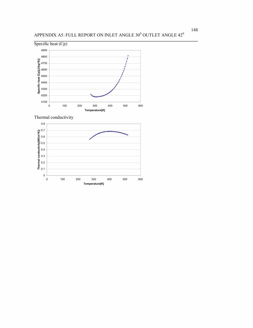
APPENDIX A5: FULL REPORT ON INLET ANGLE 300 OUTLET ANGLE 420148
Specific heat (Cp)
4100
4200
4300
4400
4500
4600
4700
4800
4900
0 100 200 300 400 500 600Temperature[K]
Spec
ific
heat
(Cp)
[J/(k
g*K
)]
Thermal conductivity
0
0.1
0.2
0.3
0.4
0.5
0.6
0.7
0.8
0 100 200 300 400 500 600Temperature[K]
Ther
mal
con
duct
ivity
[W/(m
*K)]

APPENDIX A6: FULL REPORT ON INLET ANGLE 300 OUTLET ANGLE 42.50149
System InfoProduct EFD.Lab 8 1.0. Build: 413Computer name FEA2User name AdministratorProcessors Dual Core AMD Opteron(tm) Processor
280( 4 processors)
Memory 16382 MB / 8388607 MBOperating system Microsoft Windows XP Professional x64
Edition Service Pack 2 (Build 3790)CAD version SolidWorks 2007 SP0CPU speed 2411 MHz
General InfoModel C:\Documents and
Settings\Administrator\Desktop\Fuhnwi\EFD_final\simulate3-2_inlet30_outlet42.5\Assem3-2_inlet30_outlet42.5.SLDASM
Project name Default (1)Project path C:\Documents and
Settings\Administrator\Desktop\Fuhnwi\EFD_final\simulate3-2_inlet30_outlet42.5\1\1.fwp
Units system SI (m-kg-s)Analysis type InternalExclude cavities without flow conditions OnCoordinate system Global coordinate systemReference axis X
INPUT DATA
Initial Mesh SettingsAutomatic initial mesh: OnResult resolution level: 5Advanced narrow channel refinement: OffRefinement in solid region: Off
Geometry ResolutionEvaluation of minimum gap size: ManualMinimum gap size: 0.04 mEvaluation of minimum wall thickness: ManualMinimum wall thickness: 0.01 m

APPENDIX A6: FULL REPORT ON INLET ANGLE 300 OUTLET ANGLE 42.50150
Computational Domain
SizeX min -0.0570569915 mX max 0.0391350085 mY min -0.040496 mY max 0.055696 mZ min -0.00305140391 mZ max 0.0135818462 m
Boundary Conditions2D plane flow NoneAt X min DefaultAt X max DefaultAt Y min DefaultAt Y max DefaultAt Z min DefaultAt Z max Default
Physical FeaturesHeat conduction in solids: OffTime dependent: OffGravitational effects: OffFlow type: Laminar onlyCavitation: OffHigh Mach number flow: OffDefault roughness: 0 micrometer
Rotating Reference FrameAxis of coordinate system ZVelocity 209.43951 m/s
Default wall conditions: Adiabatic wall
Initial ConditionsThermodynamic parameters Static Pressure: 101325 Pa
Temperature: 293.2 KVelocity parameters Velocity vector
Velocity in X direction: 0 m/sVelocity in Y direction: 0 m/sVelocity in Z direction: 0 m/sRelative to rotating frame: Off

APPENDIX A6: FULL REPORT ON INLET ANGLE 300 OUTLET ANGLE 42.50151
Material Settings
FluidsWater
Boundary ConditionsEnvironment Pressure 1Type Environment PressureFaces Face <1 >Coordinate system Global coordinate systemReference axis XThermodynamic parameters Environment pressure: 101325 Pa
Temperature: 293.2 K
Inlet Volume Flow 1Type Inlet Volume FlowFaces Face <1 >Coordinate system Face Coordinate SystemReference axis XFlow parameters Flow vectors direction: Normal to face
Volume flow rate normal to face: 0.3 m^3/sRelative to rotating frame: NoFully developed flow: NoInlet profile: 0
Thermodynamic parameters Temperature: 293.2 K
stator WallType Real wallFaces Face <1 >
Face <1 >Face <1 >
Coordinate system Global coordinate systemReference axis X
Goals
Global GoalsGG Z - Component of Torque 1Type Global GoalGoal type Z - Component of TorqueCoordinate system Global coordinate systemUse in convergence On

APPENDIX A6: FULL REPORT ON INLET ANGLE 300 OUTLET ANGLE 42.50152
Surface GoalsSG Z - Component of Torque at statorType Surface GoalGoal type Z - Component of TorqueFaces Face<1>@cover3-2-1
Face<2>@cover3-2-1Face<3>@cover3-2-1
Coordinate system Global coordinate systemUse in convergence On
Equation GoalsTorque on impellerType Equation GoalFormula GG Z - Component of Torque 1-SG Z -
Component of Torque at statorDimensionality TorqueUse in convergence On
Component Control InfoDisabled components: Extrude1@measure3-2-1@Assem3-2_inlet30_outlet42.5
Calculation Control Options
Finish ConditionsFinish conditions If one is satisfiedMaximum travels 4Goals convergence Analysis interval: 0.5
Solver RefinementRefinement: Disabled
Results SavingSave before refinement On
Advanced Control OptionsFlow FreezingFlow freezing strategy Disabled

APPENDIX A6: FULL REPORT ON INLET ANGLE 300 OUTLET ANGLE 42.50153
RESULTS
General InfoIterations: 276CPU time: 1157 s
LogPreparing data for calculation 12:21:21 , Feb 29Calculation started 0 12:21:27 , Feb 29Calculation has converged since thefollowing criteria are satisfied: 275
12:40:47 , Feb 29
Goals are converged 275Calculation finished 276 12:40:52 , Feb 29
Warnings: Negative pressure Minimum pressure=-1.21734e+008 Pa; dV/V=0.504098
A vortex crosses the pressure opening Boundary Condition : Environment Pressure1 ; Inlet flow/outlet flow=0.0849548
Calculation Mesh
Basic Mesh DimensionsNumber of cells in X 40Number of cells in Y 40Number of cells in Z 6
Number Of CellsTotal cells 49780Fluid cells 22439Solid cells 11284Partial cells 16057Irregular cells 0Trimmed cells 38
Maximum refinement level: 1
GoalsName Unit Value Progress Use in
convergence
Delta Criteria
GG Z - N*m 3187.23 100 On 1.5603166 20.288925

APPENDIX A6: FULL REPORT ON INLET ANGLE 300 OUTLET ANGLE 42.50154
Component ofTorque 1
5
SG Z -Component ofTorque atstator
N*m -10.9974 100 On 0.26114139
0.366912071
Torque onimpeller
N*m 3198.23 100 On 1.82467607
20.6328398
Min/Max TableName Minimum MaximumPressure [Pa] -1.21734e+008 1.68384e+008Temperature [K] 242.239 300.861Density [kg/m^3] 995.638 1001.3Velocity [m/s] 0 694.135X-velocity [m/s] -548.479 541.447Y-velocity [m/s] -548.039 521.587Z-velocity [m/s] -565.744 494.278Heat Transfer Coefficient[W/m^2/K]
0 0
Shear Stress [Pa] 1.31261e-005 3.90199e+006Surface Heat Flux [W/m^2] 0 0Water Mass Fraction [ ] 1 1Water Volume Fraction [ ] 1 1Fluid Temperature [K] 242.239 300.861Velocity RRF [m/s] 0 691.722X-velocity RRF [m/s] -555.461 546.438Y-velocity RRF [m/s] -548.555 528.122Z-velocity RRF [m/s] -565.744 494.278
Engineering Database
Liquids
WaterPath: Liquid FW Defined

APPENDIX A6: FULL REPORT ON INLET ANGLE 300 OUTLET ANGLE 42.50155
Density
0
200
400
600
800
1000
1200
0 100 200 300 400 500 600Temperature[K]
Den
sity
[kg/
m^3
]
Dynamic viscosity
0
0.0002
0.0004
0.0006
0.0008
0.001
0.0012
0.0014
0.0016
0.0018
0.002
0 100 200 300 400 500 600Temperature[K]
Dyn
amic
vis
cosi
ty[P
a*s]
Specific heat (Cp)
4100
4200
4300
4400
4500
4600
4700
4800
4900
0 100 200 300 400 500 600Temperature[K]
Spec
ific
heat
(Cp)
[J/(k
g*K
)]

APPENDIX A6: FULL REPORT ON INLET ANGLE 300 OUTLET ANGLE 42.50156
Thermal conductivity
0
0.1
0.2
0.3
0.4
0.5
0.6
0.7
0.8
0 100 200 300 400 500 600Temperature[K]
Ther
mal
con
duct
ivity
[W/(m
*K)]

APPENDIX A7: FULL REPORT ON INLET ANGLE 300 OUTLET ANGLE 440157
System InfoProduct EFD.Lab 8 1.0. Build: 413Computer name FEA2User name AdministratorProcessors Dual Core AMD Opteron(tm) Processor
280( 4 processors)
Memory 16382 MB / 8388607 MBOperating system Microsoft Windows XP Professional x64
Edition Service Pack 2 (Build 3790)CAD version SolidWorks 2007 SP0CPU speed 2411 MHz
General InfoModel C:\Documents and
Settings\Administrator\Desktop\Fuhnwi\EFD_final\simulate5_inlet30_outlet44\Assembly3_inlet30_outlet44.SLDASM
Project name inlet30_outlet44Project path C:\Documents and
Settings\Administrator\Desktop\Fuhnwi\EFD_final\simulate5_inlet30_outlet44\1\1.fwp
Units system SI (m-kg-s)Analysis type InternalExclude cavities without flow conditions OnCoordinate system Global coordinate systemReference axis X
INPUT DATA
Initial Mesh SettingsAutomatic initial mesh: OnResult resolution level: 5Advanced narrow channel refinement: OffRefinement in solid region: Off
Geometry ResolutionEvaluation of minimum gap size: ManualMinimum gap size: 0.04 mEvaluation of minimum wall thickness: ManualMinimum wall thickness: 0.01 m

APPENDIX A7: FULL REPORT ON INLET ANGLE 300 OUTLET ANGLE 440158
Computational Domain
SizeX min -0.0561376687 mX max 0.0400543313 mY min -0.0416994091 mY max 0.0544925909 mZ min -0.00871892053 mZ max 0.00791432957 m
Boundary Conditions2D plane flow NoneAt X min DefaultAt X max DefaultAt Y min DefaultAt Y max DefaultAt Z min DefaultAt Z max Default
Physical FeaturesHeat conduction in solids: OffTime dependent: OffGravitational effects: OffFlow type: Laminar onlyCavitation: OffHigh Mach number flow: OffDefault roughness: 0 micrometer
Rotating Reference FrameAxis of coordinate system ZVelocity 209.43951 m/s
Default wall conditions: Adiabatic wall
Initial ConditionsThermodynamic parameters Static Pressure: 101325 Pa
Temperature: 293.2 KVelocity parameters Velocity vector
Velocity in X direction: 0 m/sVelocity in Y direction: 0 m/sVelocity in Z direction: 0 m/sRelative to rotating frame: Off

APPENDIX A7: FULL REPORT ON INLET ANGLE 300 OUTLET ANGLE 440159
Material Settings
FluidsWater
Boundary ConditionsInlet Volume Flow 1Type Inlet Volume FlowFaces Face <1 cover3-1@>Coordinate system Face Coordinate SystemReference axis XFlow parameters Flow vectors direction: Normal to face
Volume flow rate normal to face: 0.3 m^3/sRelative to rotating frame: NoFully developed flow: NoInlet profile: 0
Thermodynamic parameters Temperature: 293.2 K
Environment Pressure 1Type Environment PressureFaces Face <1 cover3-1@>Coordinate system Global coordinate systemReference axis XThermodynamic parameters Environment pressure: 101325 Pa
Temperature: 293.2 K
stator wallsType Real wallFaces Face <1 cover3-1@>
Face <1 cover3-1@>Face <1 cover3-1@>
Coordinate system Global coordinate systemReference axis X
Goals
Global GoalsGG Z - Component of TorqueType Global GoalGoal type Z - Component of TorqueCoordinate system Global coordinate systemUse in convergence On

APPENDIX A7: FULL REPORT ON INLET ANGLE 300 OUTLET ANGLE 440160
Surface GoalsSG Mass Flow Rate at inletType Surface GoalGoal type Mass Flow RateFaces Face<5>@cover3-1Coordinate system Global coordinate systemUse in convergence On
SG Av Static Pressure at inletType Surface GoalGoal type Static PressureCalculate Average valueFaces Face<2>@cover3-1Coordinate system Global coordinate systemUse in convergence On
SG Z - Compont of Torque at statorType Surface GoalGoal type Z - Component of TorqueFaces Face<1>@cover3-1
Face<2>@cover3-1Face<3>@cover3-1
Coordinate system Global coordinate systemUse in convergence On
SG Mass Flow Rate at outletType Surface GoalGoal type Mass Flow RateFaces Face<2>@cover3-1Coordinate system Global coordinate systemUse in convergence On
SG Bulk Av Static Pressure at impeller outletType Surface GoalGoal type Static PressureCalculate Average valueFaces Face<2>@measure3-1Coordinate system Global coordinate systemUse in convergence On
Equation GoalsPressure dropType Equation GoalFormula SG Av Static Pressure at inlet-SG Bulk Av

APPENDIX A7: FULL REPORT ON INLET ANGLE 300 OUTLET ANGLE 440161
Static Pressure at impeller outletDimensionality Pressure & stressUse in convergence On
Torque on impellerType Equation GoalFormula GG Z - Component of Torque -SG Z -
Compont of Torque at statorDimensionality TorqueUse in convergence On
EfficiencyType Equation GoalFormula Pressure drop*{Inlet Volume Flow
1:Volume flow rate normal to face:3.000e-001}/209.44/Torque on impeller
Dimensionality No unitsUse in convergence On
Component Control InfoDisabled components: Extrude1@measure3-1@Assembly3_inlet30_outlet44
Calculation Control Options
Finish ConditionsFinish conditions If one is satisfiedMaximum travels 4Goals convergence Analysis interval: 0.5
Solver RefinementRefinement: Disabled
Results SavingSave before refinement On
Advanced Control OptionsFlow FreezingFlow freezing strategy Disabled

APPENDIX A7: FULL REPORT ON INLET ANGLE 300 OUTLET ANGLE 440162
RESULTS
General InfoIterations: 211CPU time: 1379 s
LogMesh generation started 13:58:24 , Feb 20Mesh generation normally finished 13:58:30 , Feb 20Preparing data for calculation 13:58:34 , Feb 20Calculation started 0 13:58:39 , Feb 20Calculation has converged since thefollowing criteria are satisfied: 210
14:21:54 , Feb 20
Goals are converged 210Calculation finished 211 14:22:06 , Feb 20
Warnings: Negative pressure Minimum pressure=-1.00924e+008 Pa; dV/V=0.49872
A vortex crosses the pressure opening Boundary Condition : Environment Pressure1 ; Inlet flow/outlet flow=0.0903678
Calculation Mesh
Basic Mesh DimensionsNumber of cells in X 40Number of cells in Y 40Number of cells in Z 6
Number Of CellsTotal cells 49717Fluid cells 22390Solid cells 11299Partial cells 16028Irregular cells 0Trimmed cells 44
Maximum refinement level: 1
GoalsName Unit Value Progress Use in
convergence
Delta Criteria
GG Z - N*m 3291.77 100 On 6.9252477 24.623115

APPENDIX A7: FULL REPORT ON INLET ANGLE 300 OUTLET ANGLE 440163
Component ofTorque
7 6
SG MassFlow Rateat inlet
kg/s 299.269 100 On 0 0.299268522
SG AvStaticPressure atinlet
Pa 1.18163e+008
100 On 499702.365
1735677.07
SG Z -Compontof Torqueat stator
N*m -6.51369 100 On 0.580797985
0.584173641
SG MassFlow Rateat outlet
kg/s -299.267 100 On 0.000388537852
0.299266781
SG BulkAv StaticPressure atimpelleroutlet
Pa -4.47208e+006
100 On 156018.175
338005.294
Torque onimpeller
N*m 3298.28 100 On 6.86668378
24.4781019
Pressuredrop
Pa 1.22635e+008
100 On 423071.402
1601275.17
Efficiency 53.2583 100 On 0.0988910288
0.35330511
Min/Max TableName Minimum MaximumPressure [Pa] -1.00924e+008 1.75694e+008Temperature [K] 244.982 300.832Density [kg/m^3] 995.657 1001.3Velocity [m/s] 0 824.89X-velocity [m/s] -554.972 541.74Y-velocity [m/s] -552.333 534.191Z-velocity [m/s] -719.921 478.582Heat Transfer Coefficient[W/m^2/K]
0 0
Shear Stress [Pa] 6.09552e-006 4.50219e+006Surface Heat Flux [W/m^2] 0 0Water Mass Fraction [ ] 1 1Water Volume Fraction [ ] 1 1Fluid Temperature [K] 244.982 300.832

APPENDIX A7: FULL REPORT ON INLET ANGLE 300 OUTLET ANGLE 440164
Velocity RRF [m/s] 0 825.247X-velocity RRF [m/s] -556.025 547.3Y-velocity RRF [m/s] -554.049 541.793Z-velocity RRF [m/s] -719.921 478.582
Engineering Database
Liquids
WaterPath: Liquid FW DefinedDensity
0
200
400
600
800
1000
1200
0 100 200 300 400 500 600Temperature[K]
Den
sity
[kg/
m^3
]
Dynamic viscosity
0
0.0002
0.0004
0.0006
0.0008
0.001
0.0012
0.0014
0.0016
0.0018
0.002
0 100 200 300 400 500 600Temperature[K]
Dyn
amic
vis
cosi
ty[P
a*s]

APPENDIX A7: FULL REPORT ON INLET ANGLE 300 OUTLET ANGLE 440165
Specific heat (Cp)
4100
4200
4300
4400
4500
4600
4700
4800
4900
0 100 200 300 400 500 600Temperature[K]
Spec
ific
heat
(Cp)
[J/(k
g*K
)]
Thermal conductivity
0
0.1
0.2
0.3
0.4
0.5
0.6
0.7
0.8
0 100 200 300 400 500 600Temperature[K]
Ther
mal
con
duct
ivity
[W/(m
*K)]

APPENDIX A8: FULL REPORT ON INLET ANGLE 300 OUTLET ANGLE 450166
System InfoProduct EFD.Lab 8 1.0. Build: 413Computer name FEA2User name AdministratorProcessors Dual Core AMD Opteron(tm) Processor
280( 4 processors)
Memory 16382 MB / 8388607 MBOperating system Microsoft Windows XP Professional x64
Edition Service Pack 2 (Build 3790)CAD version SolidWorks 2007 SP0CPU speed 2411 MHz
General InfoModel C:\Documents and
Settings\Administrator\Desktop\Fuhnwi\EFD_final\simulate6_inlet30_outlet45\Assembly3_inlet30_outlet45.SLDASM
Project name inlet30_out45Project path C:\Documents and
Settings\Administrator\Desktop\Fuhnwi\EFD_final\simulate6_inlet30_outlet45\1\1.fwp
Units system SI (m-kg-s)Analysis type InternalExclude cavities without flow conditions OnCoordinate system Global coordinate systemReference axis X
INPUT DATA
Initial Mesh SettingsAutomatic initial mesh: OnResult resolution level: 5Advanced narrow channel refinement: OffRefinement in solid region: Off
Geometry ResolutionEvaluation of minimum gap size: ManualMinimum gap size: 0.04 mEvaluation of minimum wall thickness: ManualMinimum wall thickness: 0.01 m

APPENDIX A8: FULL REPORT ON INLET ANGLE 300 OUTLET ANGLE 450167
Computational Domain
SizeX min -0.0561376687 mX max 0.0400543313 mY min -0.0416994091 mY max 0.0544925909 mZ min -0.00871892053 mZ max 0.00791432957 m
Boundary Conditions2D plane flow NoneAt X min DefaultAt X max DefaultAt Y min DefaultAt Y max DefaultAt Z min DefaultAt Z max Default
Physical FeaturesHeat conduction in solids: OffTime dependent: OffGravitational effects: OffFlow type: Laminar onlyCavitation: OffHigh Mach number flow: OffDefault roughness: 0 micrometer
Rotating Reference FrameAxis of coordinate system ZVelocity 209.43951 m/s
Default wall conditions: Adiabatic wall
Initial ConditionsThermodynamic parameters Static Pressure: 101325 Pa
Temperature: 293.2 KVelocity parameters Velocity vector
Velocity in X direction: 0 m/sVelocity in Y direction: 0 m/sVelocity in Z direction: 0 m/sRelative to rotating frame: Off

APPENDIX A8: FULL REPORT ON INLET ANGLE 300 OUTLET ANGLE 450168
Material Settings
FluidsWater
Boundary ConditionsEnvironment Pressure 1Type Environment PressureFaces Face <1 cover3-1@>Coordinate system Global coordinate systemReference axis XThermodynamic parameters Environment pressure: 101325 Pa
Temperature: 293.2 K
Inlet Volume Flow 1Type Inlet Volume FlowFaces Face <1 cover3-1@>Coordinate system Face Coordinate SystemReference axis XFlow parameters Flow vectors direction: Normal to face
Volume flow rate normal to face: 0.3 m^3/sRelative to rotating frame: NoFully developed flow: NoInlet profile: 0
Thermodynamic parameters Temperature: 293.2 K
stator wallType Real wallFaces Face <1 cover3-1@>
Face <1 cover3-1@>Face <1 cover3-1@>
Coordinate system Global coordinate systemReference axis X
Goals
Global GoalsGG Z - Component of TorqueType Global GoalGoal type Z - Component of TorqueCoordinate system Global coordinate systemUse in convergence On
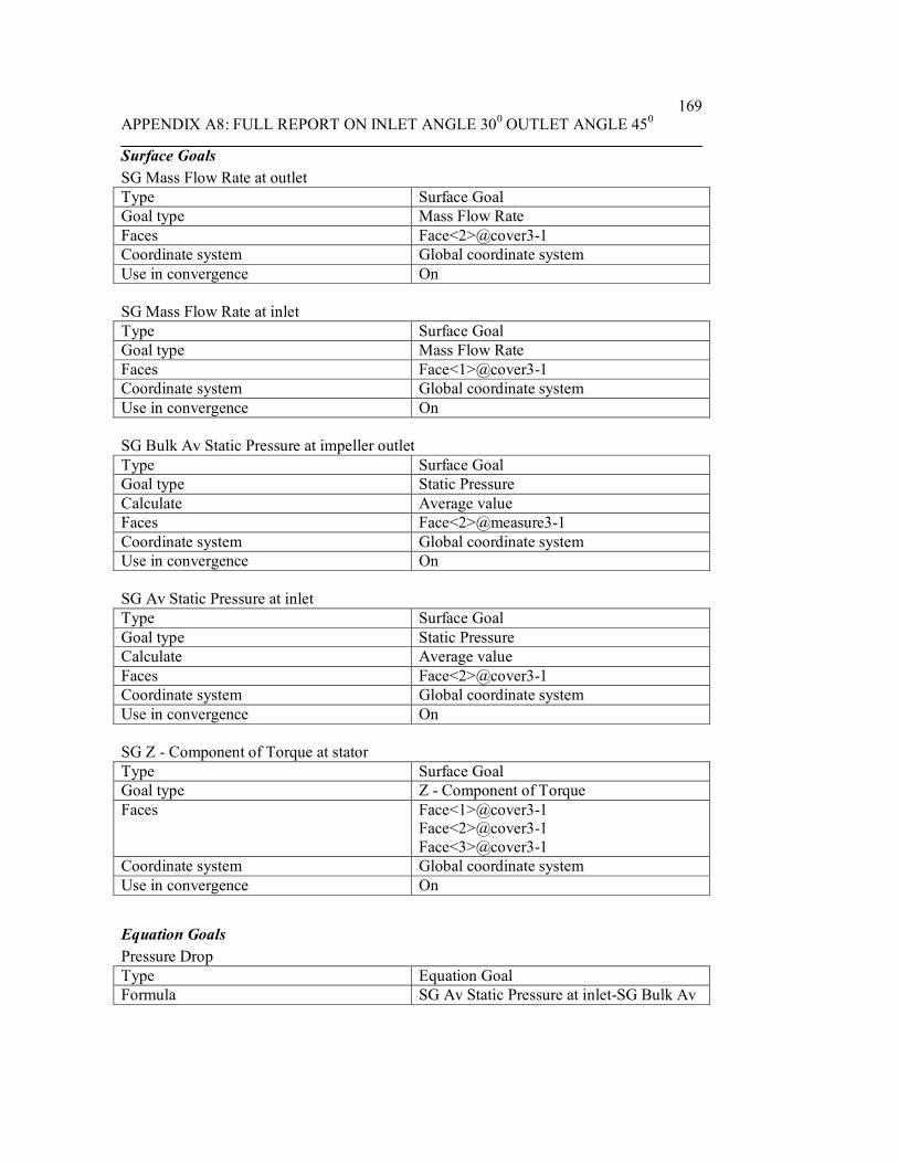
APPENDIX A8: FULL REPORT ON INLET ANGLE 300 OUTLET ANGLE 450169
Surface GoalsSG Mass Flow Rate at outletType Surface GoalGoal type Mass Flow RateFaces Face<2>@cover3-1Coordinate system Global coordinate systemUse in convergence On
SG Mass Flow Rate at inletType Surface GoalGoal type Mass Flow RateFaces Face<1>@cover3-1Coordinate system Global coordinate systemUse in convergence On
SG Bulk Av Static Pressure at impeller outletType Surface GoalGoal type Static PressureCalculate Average valueFaces Face<2>@measure3-1Coordinate system Global coordinate systemUse in convergence On
SG Av Static Pressure at inletType Surface GoalGoal type Static PressureCalculate Average valueFaces Face<2>@cover3-1Coordinate system Global coordinate systemUse in convergence On
SG Z - Component of Torque at statorType Surface GoalGoal type Z - Component of TorqueFaces Face<1>@cover3-1
Face<2>@cover3-1Face<3>@cover3-1
Coordinate system Global coordinate systemUse in convergence On
Equation GoalsPressure DropType Equation GoalFormula SG Av Static Pressure at inlet-SG Bulk Av

APPENDIX A8: FULL REPORT ON INLET ANGLE 300 OUTLET ANGLE 450170
Static Pressure at impeller outletDimensionality Pressure & stressUse in convergence On
Torque on impellerType Equation GoalFormula GG Z - Component of Torque -SG Z -
Component of Torque at statorDimensionality TorqueUse in convergence On
Equation Goal 1Type Equation GoalFormula Pressure Drop*{Inlet Volume Flow
1:Volume flow rate normal to face:3.000e-001}/209.44/Torque on impeller
Dimensionality No unitsUse in convergence On
Component Control InfoDisabled components: Extrude1@measure3-1@Assembly3_inlet30_outlet45
Calculation Control Options
Finish ConditionsFinish conditions If one is satisfiedMaximum travels 4Goals convergence Analysis interval: 0.5
Solver RefinementRefinement: Disabled
Results SavingSave before refinement On
Advanced Control OptionsFlow FreezingFlow freezing strategy Disabled
RESULTS
General InfoIterations: 168

APPENDIX A8: FULL REPORT ON INLET ANGLE 300 OUTLET ANGLE 450171
CPU time: 746 s
LogMesh generation started 15:01:13 , Feb 20Mesh generation normally finished 15:01:20 , Feb 20Preparing data for calculation 15:01:24 , Feb 20Calculation started 0 15:01:28 , Feb 20Calculation has converged since thefollowing criteria are satisfied: 167
15:14:01 , Feb 20
Goals are converged 167Calculation finished 168 15:14:12 , Feb 20
Warnings: Negative pressure Minimum pressure=-1.01975e+008 Pa; dV/V=0.500823
A vortex crosses the pressure opening Boundary Condition : Environment Pressure1 ; Inlet flow/outlet flow=0.0884177
Calculation Mesh
Basic Mesh DimensionsNumber of cells in X 40Number of cells in Y 40Number of cells in Z 6
Number Of CellsTotal cells 49801Fluid cells 22314Solid cells 11419Partial cells 16068Irregular cells 0Trimmed cells 35
Maximum refinement level: 1
GoalsName Unit Value Progress Use in
convergence
Delta Criteria
GG Z -Component ofTorque
N*m 3308.62 100 On 11.5432768
28.0025068
SG Mass kg/s -299.269 100 On 0.0007813 0.2992687

APPENDIX A8: FULL REPORT ON INLET ANGLE 300 OUTLET ANGLE 450172
Flow Rateat outlet
25122 01
SG MassFlow Rateat inlet
kg/s 299.269 100 On 0 0.299268522
SG BulkAv StaticPressure atimpelleroutlet
Pa -4.44126e+006
100 On 169242.835
350593.796
SG AvStaticPressure atinlet
Pa 1.19047e+008
100 On 496570.855
1894350.07
SG Z -Component ofTorque atstator
N*m -4.38065 100 On 0.444504628
0.456384513
Torque onimpeller
N*m 3313 100 On 11.7995962
27.9005724
PressureDrop
Pa 1.23488e+008
100 On 520012.709
1751805.78
Efficiency 53.3907 100 On 0.137089653
0.353518209
Min/Max TableName Minimum MaximumPressure [Pa] -1.01975e+008 1.767e+008Temperature [K] 243.247 300.858Density [kg/m^3] 995.626 1001.3Velocity [m/s] 0 838.928X-velocity [m/s] -550.088 545.129Y-velocity [m/s] -557.937 539.49Z-velocity [m/s] -733.777 472.716Heat Transfer Coefficient[W/m^2/K]
0 0
Shear Stress [Pa] 9.01013e-006 393215Surface Heat Flux [W/m^2] 0 0Water Mass Fraction [ ] 1 1Water Volume Fraction [ ] 1 1Fluid Temperature [K] 243.247 300.858Velocity RRF [m/s] 0 839.283X-velocity RRF [m/s] -551.141 550.624

APPENDIX A8: FULL REPORT ON INLET ANGLE 300 OUTLET ANGLE 450173
Y-velocity RRF [m/s] -561.699 547.093Z-velocity RRF [m/s] -733.777 472.716
Engineering Database
Liquids
WaterPath: Liquid FW DefinedDensity
0
200
400
600
800
1000
1200
0 100 200 300 400 500 600Temperature[K]
Den
sity
[kg/
m^3
]
Dynamic viscosity
0
0.0002
0.0004
0.0006
0.0008
0.001
0.0012
0.0014
0.0016
0.0018
0.002
0 100 200 300 400 500 600Temperature[K]
Dyn
amic
vis
cosi
ty[P
a*s]

APPENDIX A8: FULL REPORT ON INLET ANGLE 300 OUTLET ANGLE 450174
Specific heat (Cp)
4100
4200
4300
4400
4500
4600
4700
4800
4900
0 100 200 300 400 500 600Temperature[K]
Spec
ific
heat
(Cp)
[J/(k
g*K
)]
Thermal conductivity
0
0.1
0.2
0.3
0.4
0.5
0.6
0.7
0.8
0 100 200 300 400 500 600Temperature[K]
Ther
mal
con
duct
ivity
[W/(m
*K)]

APPENDIX A9: FULL REPORT ON INLET ANGLE 300 OUTLET ANGLE 460175
System InfoProduct EFD.Lab 8 1.0. Build: 413Computer name FEA2User name AdministratorProcessors Dual Core AMD Opteron(tm) Processor
280( 4 processors)
Memory 16382 MB / 8388607 MBOperating system Microsoft Windows XP Professional x64
Edition Service Pack 2 (Build 3790)CAD version SolidWorks 2007 SP0CPU speed 2411 MHz
General InfoModel C:\Documents and
Settings\Administrator\Desktop\Fuhnwi\EFD_final\simulate7_inlet30_outlet46\Assem4_inlet30_outlet46.SLDASM
Project name inlet30_outlet46Project path C:\Documents and
Settings\Administrator\Desktop\Fuhnwi\EFD_final\simulate7_inlet30_outlet46\1\1.fwp
Units system SI (m-kg-s)Analysis type InternalExclude cavities without flow conditions OnCoordinate system Global coordinate systemReference axis X
INPUT DATA
Initial Mesh SettingsAutomatic initial mesh: OnResult resolution level: 5Advanced narrow channel refinement: OffRefinement in solid region: Off
Geometry ResolutionEvaluation of minimum gap size: ManualMinimum gap size: 0.04 mEvaluation of minimum wall thickness: ManualMinimum wall thickness: 0.01 m

APPENDIX A9: FULL REPORT ON INLET ANGLE 300 OUTLET ANGLE 460176
Computational Domain
SizeX min -0.0459669402 mX max 0.0502250598 mY min -0.0401346033 mY max 0.0560573967 mZ min -0.00654898132 mZ max 0.0100842688 m
Boundary Conditions2D plane flow NoneAt X min DefaultAt X max DefaultAt Y min DefaultAt Y max DefaultAt Z min DefaultAt Z max Default
Physical FeaturesHeat conduction in solids: OffTime dependent: OffGravitational effects: OffFlow type: Laminar onlyCavitation: OffHigh Mach number flow: OffDefault roughness: 0 micrometer
Rotating Reference FrameAxis of coordinate system ZVelocity 209.43951 m/s
Default wall conditions: Adiabatic wall
Initial ConditionsThermodynamic parameters Static Pressure: 101325 Pa
Temperature: 293.2 KVelocity parameters Velocity vector
Velocity in X direction: 0 m/sVelocity in Y direction: 0 m/sVelocity in Z direction: 0 m/sRelative to rotating frame: Off

APPENDIX A9: FULL REPORT ON INLET ANGLE 300 OUTLET ANGLE 460177
Material Settings
FluidsWater
Boundary ConditionsInlet Volume Flow 1Type Inlet Volume FlowFaces Face <1 cover4-1@>Coordinate system Face Coordinate SystemReference axis XFlow parameters Flow vectors direction: Normal to face
Volume flow rate normal to face: 0.3 m^3/sRelative to rotating frame: NoFully developed flow: NoInlet profile: 0
Thermodynamic parameters Temperature: 293.2 K
stator wallsType Real wallFaces Face <1 cover4-1@>
Face <1 cover4-1@>Face <1 cover4-1@>
Coordinate system Global coordinate systemReference axis X
Environment Pressure 1Type Environment PressureFaces Face <1 cover4-1@>Coordinate system Global coordinate systemReference axis XThermodynamic parameters Environment pressure: 101325 Pa
Temperature: 293.2 K
Goals
Global GoalsGG Z - Component of TorqueType Global GoalGoal type Z - Component of TorqueCoordinate system Global coordinate systemUse in convergence On
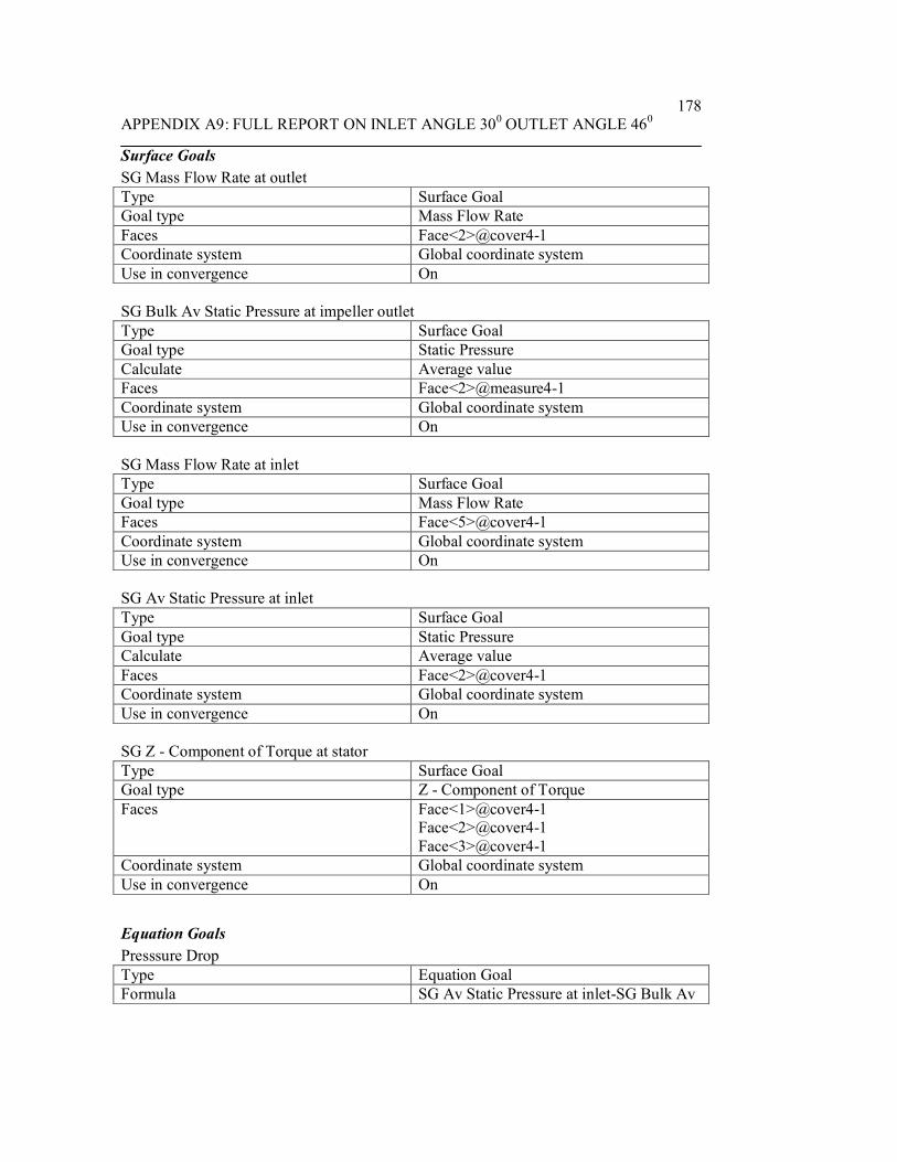
APPENDIX A9: FULL REPORT ON INLET ANGLE 300 OUTLET ANGLE 460178
Surface GoalsSG Mass Flow Rate at outletType Surface GoalGoal type Mass Flow RateFaces Face<2>@cover4-1Coordinate system Global coordinate systemUse in convergence On
SG Bulk Av Static Pressure at impeller outletType Surface GoalGoal type Static PressureCalculate Average valueFaces Face<2>@measure4-1Coordinate system Global coordinate systemUse in convergence On
SG Mass Flow Rate at inletType Surface GoalGoal type Mass Flow RateFaces Face<5>@cover4-1Coordinate system Global coordinate systemUse in convergence On
SG Av Static Pressure at inletType Surface GoalGoal type Static PressureCalculate Average valueFaces Face<2>@cover4-1Coordinate system Global coordinate systemUse in convergence On
SG Z - Component of Torque at statorType Surface GoalGoal type Z - Component of TorqueFaces Face<1>@cover4-1
Face<2>@cover4-1Face<3>@cover4-1
Coordinate system Global coordinate systemUse in convergence On
Equation GoalsPresssure DropType Equation GoalFormula SG Av Static Pressure at inlet-SG Bulk Av

APPENDIX A9: FULL REPORT ON INLET ANGLE 300 OUTLET ANGLE 460179
Static Pressure at impeller outletDimensionality Pressure & stressUse in convergence On
Torque on impellerType Equation GoalFormula GG Z - Component of Torque -SG Z -
Component of Torque at statorDimensionality TorqueUse in convergence On
EfficiencyType Equation GoalFormula Presssure Drop*{Inlet Volume Flow
1:Volume flow rate normal to face:3.000e-001}/209.44/Torque on impeller
Dimensionality No unitsUse in convergence On
Component Control InfoDisabled components: Extrude1@measure4-1@Assem4_inlet30_outlet46
Calculation Control Options
Finish ConditionsFinish conditions If one is satisfiedMaximum travels 4Goals convergence Analysis interval: 0.5
Solver RefinementRefinement: Disabled
Results SavingSave before refinement On
Advanced Control OptionsFlow FreezingFlow freezing strategy Disabled
RESULTS
General InfoIterations: 162

APPENDIX A9: FULL REPORT ON INLET ANGLE 300 OUTLET ANGLE 460180
CPU time: 718 s
LogMesh generation started 15:40:10 , Feb 20Mesh generation normally finished 15:40:16 , Feb 20Preparing data for calculation 15:40:21 , Feb 20Calculation started 0 15:40:25 , Feb 20Calculation has converged since thefollowing criteria are satisfied: 161
15:52:25 , Feb 20
Goals are converged 161Calculation finished 162 15:52:32 , Feb 20
Warnings: Negative pressure Minimum pressure=-1.01684e+008 Pa; dV/V=0.5131
A vortex crosses the pressure opening Boundary Condition : Environment Pressure1 ; Inlet flow/outlet flow=0.0851425
Calculation Mesh
Basic Mesh DimensionsNumber of cells in X 40Number of cells in Y 40Number of cells in Z 6
Number Of CellsTotal cells 49780Fluid cells 22275Solid cells 11428Partial cells 16077Irregular cells 0Trimmed cells 36
Maximum refinement level: 1
GoalsName Unit Value Progress Use in
convergence
Delta Criteria
GG Z -Component ofTorque
N*m 3327.77 100 On 11.0983986
28.6026344
SG Mass kg/s -299.268 100 On 0.0005547 0.2992682

APPENDIX A9: FULL REPORT ON INLET ANGLE 300 OUTLET ANGLE 460181
Flow Rateat outlet
94172 25
SG BulkAv StaticPressure atimpelleroutlet
Pa -4.6558e+006
100 On 336988.293
348918.786
SG MassFlow Rateat inlet
kg/s 299.269 100 On 0 0.299268522
SG AvStaticPressure atinlet
Pa 1.19439e+008
100 On 265061.964
1889093.74
SG Z -Component ofTorque atstator
N*m -6.21354 100 On 0.618890114
0.904380404
Torque onimpeller
N*m 3333.99 100 On 11.641144 28.2454649
PresssureDrop
Pa 1.24094e+008
100 On 374645.28 1747969.81
Efficiency 53.315 100 On 0.153753912
0.343020986
Min/Max TableName Minimum MaximumPressure [Pa] -1.01684e+008 1.76654e+008Temperature [K] 241.981 300.826Density [kg/m^3] 995.614 1001.3Velocity [m/s] 0 830.851X-velocity [m/s] -545.557 561.885Y-velocity [m/s] -553.021 556.792Z-velocity [m/s] -723.228 410.195Heat Transfer Coefficient[W/m^2/K]
0 0
Shear Stress [Pa] 3.51288e-006 4.52508e+006Surface Heat Flux [W/m^2] 0 0Water Mass Fraction [ ] 1 1Water Volume Fraction [ ] 1 1Fluid Temperature [K] 241.981 300.826Velocity RRF [m/s] 0 830.675X-velocity RRF [m/s] -549.808 571.867

APPENDIX A9: FULL REPORT ON INLET ANGLE 300 OUTLET ANGLE 460182
Y-velocity RRF [m/s] -555.859 562.012Z-velocity RRF [m/s] -723.228 410.195
Engineering Database
Liquids
WaterPath: Liquid FW DefinedDensity
0
200
400
600
800
1000
1200
0 100 200 300 400 500 600Temperature[K]
Den
sity
[kg/
m^3
]
Dynamic viscosity
0
0.0002
0.0004
0.0006
0.0008
0.001
0.0012
0.0014
0.0016
0.0018
0.002
0 100 200 300 400 500 600Temperature[K]
Dyn
amic
vis
cosi
ty[P
a*s]

APPENDIX A9: FULL REPORT ON INLET ANGLE 300 OUTLET ANGLE 460183
Specific heat (Cp)
4100
4200
4300
4400
4500
4600
4700
4800
4900
0 100 200 300 400 500 600Temperature[K]
Spec
ific
heat
(Cp)
[J/(k
g*K
)]
Thermal conductivity
0
0.1
0.2
0.3
0.4
0.5
0.6
0.7
0.8
0 100 200 300 400 500 600Temperature[K]
Ther
mal
con
duct
ivity
[W/(m
*K)]

APPENDIX A10: FULL REPORT ON INLET ANGLE 300 OUTLET ANGLE 480183
System InfoProduct EFD.Lab 8 1.0. Build: 413Computer name FEA2User name AdministratorProcessors Dual Core AMD Opteron(tm) Processor
280( 4 processors)
Memory 16382 MB / 8388607 MBOperating system Microsoft Windows XP Professional x64
Edition Service Pack 2 (Build 3790)CAD version SolidWorks 2007 SP0CPU speed 2411 MHz
General InfoModel C:\Documents and
Settings\Administrator\Desktop\Fuhnwi\EFD_final\simulate8_inlet30_outlet48\Assem5_inlet30_outlet48.SLDASM
Project name inlet30_outlet48Project path C:\Documents and
Settings\Administrator\Desktop\Fuhnwi\EFD_final\simulate8_inlet30_outlet48\1\1.fwp
Units system SI (m-kg-s)Analysis type InternalExclude cavities without flow conditions OnCoordinate system Global coordinate systemReference axis X
INPUT DATA
Initial Mesh SettingsAutomatic initial mesh: OnResult resolution level: 5Advanced narrow channel refinement: OffRefinement in solid region: Off
Geometry ResolutionEvaluation of minimum gap size: ManualMinimum gap size: 0.04 mEvaluation of minimum wall thickness: ManualMinimum wall thickness: 0.01 m
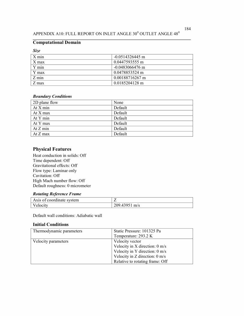
APPENDIX A10: FULL REPORT ON INLET ANGLE 300 OUTLET ANGLE 480184
Computational Domain
SizeX min -0.0514326445 mX max 0.0447593555 mY min -0.0483066476 mY max 0.0478853524 mZ min 0.00188716267 mZ max 0.0185204128 m
Boundary Conditions2D plane flow NoneAt X min DefaultAt X max DefaultAt Y min DefaultAt Y max DefaultAt Z min DefaultAt Z max Default
Physical FeaturesHeat conduction in solids: OffTime dependent: OffGravitational effects: OffFlow type: Laminar onlyCavitation: OffHigh Mach number flow: OffDefault roughness: 0 micrometer
Rotating Reference FrameAxis of coordinate system ZVelocity 209.43951 m/s
Default wall conditions: Adiabatic wall
Initial ConditionsThermodynamic parameters Static Pressure: 101325 Pa
Temperature: 293.2 KVelocity parameters Velocity vector
Velocity in X direction: 0 m/sVelocity in Y direction: 0 m/sVelocity in Z direction: 0 m/sRelative to rotating frame: Off

APPENDIX A10: FULL REPORT ON INLET ANGLE 300 OUTLET ANGLE 480185
Material Settings
FluidsWater
Boundary Conditionsstator wallsType Real wallFaces Face <1 cover5-1@>
Face <1 cover5-1@>Face <1 cover5-1@>
Coordinate system Global coordinate systemReference axis X
Inlet Volume Flow 1Type Inlet Volume FlowFaces Face <1 cover5-1@>Coordinate system Face Coordinate SystemReference axis XFlow parameters Flow vectors direction: Normal to face
Volume flow rate normal to face: 0.3 m^3/sRelative to rotating frame: NoFully developed flow: NoInlet profile: 0
Thermodynamic parameters Temperature: 293.2 K
Environment Pressure 1Type Environment PressureFaces Face <1 cover5-1@>Coordinate system Global coordinate systemReference axis XThermodynamic parameters Environment pressure: 101325 Pa
Temperature: 293.2 K
Goals
Global GoalsGG Z - Component of TorqueType Global GoalGoal type Z - Component of TorqueCoordinate system Global coordinate systemUse in convergence On

APPENDIX A10: FULL REPORT ON INLET ANGLE 300 OUTLET ANGLE 480186
Surface GoalsSG Bulk Av Static Pressure at impeller outletType Surface GoalGoal type Static PressureCalculate Average valueFaces Face<2>@measure5-1Coordinate system Global coordinate systemUse in convergence On
SG Z - Component of Torque at statorType Surface GoalGoal type Z - Component of TorqueFaces Face<1>@cover5-1
Face<3>@cover5-1Face<2>@cover5-1
Coordinate system Global coordinate systemUse in convergence On
SG Mass Flow Rate at inletType Surface GoalGoal type Mass Flow RateFaces Face<5>@cover5-1Coordinate system Global coordinate systemUse in convergence On
SG Mass Flow Rate at outletType Surface GoalGoal type Mass Flow RateFaces Face<2>@cover5-1Coordinate system Global coordinate systemUse in convergence On
SG Av Static Pressure at inletType Surface GoalGoal type Static PressureCalculate Average valueFaces Face<2>@cover5-1Coordinate system Global coordinate systemUse in convergence On
Equation GoalsPressure DropType Equation GoalFormula SG Av Static Pressure at inlet-SG Bulk Av

APPENDIX A10: FULL REPORT ON INLET ANGLE 300 OUTLET ANGLE 480187
Static Pressure at impeller outletDimensionality Pressure & stressUse in convergence On
Torque on impellerType Equation GoalFormula GG Z - Component of Torque -SG Z -
Component of Torque at statorDimensionality TorqueUse in convergence On
EfficiencyType Equation GoalFormula Pressure Drop*{Inlet Volume Flow
1:Volume flow rate normal to face:3.000e-001}/209.44/Torque on impeller
Dimensionality No unitsUse in convergence On
Component Control InfoDisabled components: Extrude1@measure5-1@Assem5_inlet30_outlet48
Calculation Control Options
Finish ConditionsFinish conditions If one is satisfiedMaximum travels 4Goals convergence Analysis interval: 0.5
Solver RefinementRefinement: Disabled
Results SavingSave before refinement On
Advanced Control OptionsFlow FreezingFlow freezing strategy Disabled

APPENDIX A10: FULL REPORT ON INLET ANGLE 300 OUTLET ANGLE 480188
RESULTS
General InfoIterations: 154CPU time: 790 s
LogMesh generation started 19:53:43 , Feb 20Mesh generation normally finished 19:53:49 , Feb 20Preparing data for calculation 19:53:55 , Feb 20Calculation started 0 19:53:59 , Feb 20Calculation has converged since thefollowing criteria are satisfied: 153
20:07:17 , Feb 20
Goals are converged 153Calculation finished 154 20:07:28 , Feb 20
Warnings: Negative pressure Minimum pressure=-1.20456e+008 Pa; dV/V=0.512009
A vortex crosses the pressure opening Boundary Condition : Environment Pressure1 ; Inlet flow/outlet flow=0.0828767
Calculation Mesh
Basic Mesh DimensionsNumber of cells in X 40Number of cells in Y 40Number of cells in Z 6
Number Of CellsTotal cells 49738Fluid cells 22328Solid cells 11278Partial cells 16132Irregular cells 0Trimmed cells 40
Maximum refinement level: 1

APPENDIX A10: FULL REPORT ON INLET ANGLE 300 OUTLET ANGLE 480189
GoalsName Unit Value Progress Use in
convergence
Delta Criteria
GG Z -Component ofTorque
N*m 3362.8 100 On 9.85940066
25.0946564
SG BulkAv StaticPressure atimpelleroutlet
Pa -4.61839e+006
100 On 287555.808
348823.543
SG Z -Component ofTorque atstator
N*m -2.65802 100 On 0.479256199
0.487791631
SG MassFlow Rateat inlet
kg/s 299.269 100 On 0 0.299268522
SG MassFlow Rateat outlet
kg/s -299.268 100 On 0.000838875871
0.299268063
SG AvStaticPressure atinlet
Pa 1.21093e+008
100 On 444174.727
1851853.85
Torque onimpeller
N*m 3365.46 100 On 9.93465644
25.0525999
PressureDrop
Pa 1.25711e+008
100 On 546823.257
1717350.7
Efficiency 53.5046 100 On 0.114821205
0.377317033
Min/Max TableName Minimum MaximumPressure [Pa] -1.20456e+008 1.78909e+008Temperature [K] 239.569 300.704Density [kg/m^3] 995.65 1001.3Velocity [m/s] 0 835.979X-velocity [m/s] -541.012 555.869Y-velocity [m/s] -555.399 544.834Z-velocity [m/s] -730.57 518.269

APPENDIX A10: FULL REPORT ON INLET ANGLE 300 OUTLET ANGLE 480190
Heat Transfer Coefficient[W/m^2/K]
0 0
Shear Stress [Pa] 7.71174e-006 4.68796e+006Surface Heat Flux [W/m^2] 0 0Water Mass Fraction [ ] 1 1Water Volume Fraction [ ] 1 1Fluid Temperature [K] 239.569 300.704Velocity RRF [m/s] 0 835.946X-velocity RRF [m/s] -546.722 559.028Y-velocity RRF [m/s] -556.841 549.688Z-velocity RRF [m/s] -730.57 518.269
Engineering Database
Liquids
WaterPath: Liquid FW DefinedDensity
0
200
400
600
800
1000
1200
0 100 200 300 400 500 600Temperature[K]
Den
sity
[kg/
m^3
]

APPENDIX A10: FULL REPORT ON INLET ANGLE 300 OUTLET ANGLE 480191
Dynamic viscosity
0
0.0002
0.0004
0.0006
0.0008
0.001
0.0012
0.0014
0.0016
0.0018
0.002
0 100 200 300 400 500 600Temperature[K]
Dyn
amic
vis
cosi
ty[P
a*s]
Specific heat (Cp)
4100
4200
4300
4400
4500
4600
4700
4800
4900
0 100 200 300 400 500 600Temperature[K]
Spec
ific
heat
(Cp)
[J/(k
g*K
)]
Thermal conductivity
0
0.1
0.2
0.3
0.4
0.5
0.6
0.7
0.8
0 100 200 300 400 500 600Temperature[K]
Ther
mal
con
duct
ivity
[W/(m
*K)]

APPENDIX A11: FULL REPORT ON INLET ANGLE 300 OUTLET ANGLE 500192
System InfoProduct EFD.Lab 8 1.0. Build: 413Computer name FEA2User name AdministratorProcessors Dual Core AMD Opteron(tm) Processor
280( 4 processors)
Memory 16382 MB / 8388607 MBOperating system Microsoft Windows XP Professional x64
Edition Service Pack 2 (Build 3790)CAD version SolidWorks 2007 SP0CPU speed 2411 MHz
General InfoModel C:\Documents and
Settings\Administrator\Desktop\Fuhnwi\EFD_final\simulate9_inlet30_outlet50\Assem4_inlet30_outlet50.SLDASM
Project name inlet30_outlet50Project path C:\Documents and
Settings\Administrator\Desktop\Fuhnwi\EFD_final\simulate9_inlet30_outlet50\1\1.fwp
Units system SI (m-kg-s)Analysis type InternalExclude cavities without flow conditions OnCoordinate system Global coordinate systemReference axis X
INPUT DATA
Initial Mesh SettingsAutomatic initial mesh: OnResult resolution level: 5Advanced narrow channel refinement: OffRefinement in solid region: Off
Geometry ResolutionEvaluation of minimum gap size: ManualMinimum gap size: 0.04 mEvaluation of minimum wall thickness: ManualMinimum wall thickness: 0.01 m

APPENDIX A11: FULL REPORT ON INLET ANGLE 300 OUTLET ANGLE 500193
Computational Domain
SizeX min -0.0459669402 mX max 0.0502250598 mY min -0.0401346033 mY max 0.0560573967 mZ min -0.00654898132 mZ max 0.0100842688 m
Boundary Conditions2D plane flow NoneAt X min DefaultAt X max DefaultAt Y min DefaultAt Y max DefaultAt Z min DefaultAt Z max Default
Physical FeaturesHeat conduction in solids: OffTime dependent: OffGravitational effects: OffFlow type: Laminar onlyCavitation: OffHigh Mach number flow: OffDefault roughness: 0 micrometer
Rotating Reference FrameAxis of coordinate system ZVelocity 209.43951 m/s
Default wall conditions: Adiabatic wall
Initial ConditionsThermodynamic parameters Static Pressure: 101325 Pa
Temperature: 293.2 KVelocity parameters Velocity vector
Velocity in X direction: 0 m/sVelocity in Y direction: 0 m/sVelocity in Z direction: 0 m/sRelative to rotating frame: Off

APPENDIX A11: FULL REPORT ON INLET ANGLE 300 OUTLET ANGLE 500194
Material Settings
FluidsWater
Boundary ConditionsInlet Volume Flow 1Type Inlet Volume FlowFaces Face <1 cover4-1@>Coordinate system Face Coordinate SystemReference axis XFlow parameters Flow vectors direction: Normal to face
Volume flow rate normal to face: 0.3 m^3/sRelative to rotating frame: NoFully developed flow: NoInlet profile: 0
Thermodynamic parameters Temperature: 293.2 K
stator WallType Real wallFaces Face <1 cover4-1@>
Face <1 cover4-1@>Face <1 cover4-1@>
Coordinate system Global coordinate systemReference axis X
Environment Pressure 1Type Environment PressureFaces Face <1 cover4-1@>Coordinate system Global coordinate systemReference axis XThermodynamic parameters Environment pressure: 101325 Pa
Temperature: 293.2 K
Goals
Global GoalsGG Z - Component of TorqueType Global GoalGoal type Z - Component of TorqueCoordinate system Global coordinate systemUse in convergence On

APPENDIX A11: FULL REPORT ON INLET ANGLE 300 OUTLET ANGLE 500195
Surface GoalsSG Bulk Av Static Pressure at impeller outletType Surface GoalGoal type Static PressureCalculate Average valueFaces Face<2>@measure4-1Coordinate system Global coordinate systemUse in convergence On
SG Mass Flow Rate at inletType Surface GoalGoal type Mass Flow RateFaces Face<5>@cover4-1Coordinate system Global coordinate systemUse in convergence On
SG Av Static Pressure at inletType Surface GoalGoal type Static PressureCalculate Average valueFaces Face<2>@cover4-1Coordinate system Global coordinate systemUse in convergence On
SG Mass Flow Rate at outletType Surface GoalGoal type Mass Flow RateFaces Face<2>@cover4-1Coordinate system Global coordinate systemUse in convergence On
SG Z - Component of Torque at statorType Surface GoalGoal type Z - Component of TorqueFaces Face<2>@cover4-1
Face<1>@cover4-1Face<3>@cover4-1
Coordinate system Global coordinate systemUse in convergence On
Equation GoalsPressure DropType Equation GoalFormula SG Av Static Pressure at inlet-SG Bulk Av

APPENDIX A11: FULL REPORT ON INLET ANGLE 300 OUTLET ANGLE 500196
Static Pressure at impeller outletDimensionality Pressure & stressUse in convergence On
Torque on impellerType Equation GoalFormula GG Z - Component of Torque -SG Z -
Component of Torque at statorDimensionality TorqueUse in convergence On
EfficiencyType Equation GoalFormula Pressure Drop*{Inlet Volume Flow
1:Volume flow rate normal to face:3.000e-001}/209.44/Torque on impeller
Dimensionality No unitsUse in convergence On
Component Control InfoDisabled components: Extrude1@measure4-1@Assem4_inlet30_outlet50
Calculation Control Options
Finish ConditionsFinish conditions If one is satisfiedMaximum travels 4Goals convergence Analysis interval: 0.5
Solver RefinementRefinement: Disabled
Results SavingSave before refinement On
Advanced Control OptionsFlow FreezingFlow freezing strategy Disabled

APPENDIX A11: FULL REPORT ON INLET ANGLE 300 OUTLET ANGLE 500197
RESULTS
General InfoIterations: 167CPU time: 736 s
LogMesh generation started 20:27:14 , Feb 20Mesh generation normally finished 20:27:21 , Feb 20Preparing data for calculation 20:27:26 , Feb 20Calculation started 0 20:27:30 , Feb 20Calculation has converged since thefollowing criteria are satisfied: 166
20:39:47 , Feb 20
Goals are converged 166Calculation finished 167 20:39:52 , Feb 20
Warnings: Negative pressure Minimum pressure=-1.20214e+008 Pa; dV/V=0.495874
A vortex crosses the pressure opening Boundary Condition : Environment Pressure1 ; Inlet flow/outlet flow=0.0866046
Calculation Mesh
Basic Mesh DimensionsNumber of cells in X 40Number of cells in Y 40Number of cells in Z 6
Number Of CellsTotal cells 49780Fluid cells 22160Solid cells 11524Partial cells 16096Irregular cells 0Trimmed cells 37
Maximum refinement level: 1
GoalsName Unit Value Progress Use in
convergenDelta Criteria

APPENDIX A11: FULL REPORT ON INLET ANGLE 300 OUTLET ANGLE 500198
ceGG Z -Component ofTorque
N*m 3421.23 100 On 15.4808611
28.9305991
SG BulkAv StaticPressure atimpelleroutlet
Pa -4.33698e+006
100 On 247330.017
370764.698
SG MassFlow Rateat inlet
kg/s 299.269 100 On 0 0.299268522
SG AvStaticPressure atinlet
Pa 1.2631e+008
100 On 198012.491
2058889.16
SG MassFlow Rateat outlet
kg/s -299.266 100 On 0.000689752417
0.299266433
SG Z -Component ofTorque atstator
N*m -9.35824 100 On 0.444954715
0.464934415
Torque onimpeller
N*m 3430.59 100 On 15.5750148
28.881947
PressureDrop
Pa 1.30647e+008
100 On 294534.863
1906635.49
Efficiency 54.5498 100 On 0.140409828
0.38022635
Min/Max TableName Minimum MaximumPressure [Pa] -1.20214e+008 1.83694e+008Temperature [K] 237.284 300.816Density [kg/m^3] 995.645 1001.3Velocity [m/s] 0 844.228X-velocity [m/s] -567.118 562.671Y-velocity [m/s] -558.323 556.048Z-velocity [m/s] -735.381 480.733Heat Transfer Coefficient[W/m^2/K]
0 0
Shear Stress [Pa] 3.57214e-006 4.81012e+006Surface Heat Flux [W/m^2] 0 0

APPENDIX A11: FULL REPORT ON INLET ANGLE 300 OUTLET ANGLE 500199
Water Mass Fraction [ ] 1 1Water Volume Fraction [ ] 1 1Fluid Temperature [K] 237.284 300.816Velocity RRF [m/s] 0 843.973X-velocity RRF [m/s] -571.866 567.487Y-velocity RRF [m/s] -561.414 559.758Z-velocity RRF [m/s] -735.381 480.733
Engineering Database
Liquids
WaterPath: Liquid FW DefinedDensity
0
200
400
600
800
1000
1200
0 100 200 300 400 500 600Temperature[K]
Den
sity
[kg/
m^3
]
Dynamic viscosity
0
0.0002
0.0004
0.0006
0.0008
0.001
0.0012
0.0014
0.0016
0.0018
0.002
0 100 200 300 400 500 600Temperature[K]
Dyn
amic
vis
cosi
ty[P
a*s]

APPENDIX A11: FULL REPORT ON INLET ANGLE 300 OUTLET ANGLE 500200
Specific heat (Cp)
4100
4200
4300
4400
4500
4600
4700
4800
4900
0 100 200 300 400 500 600Temperature[K]
Spec
ific
heat
(Cp)
[J/(k
g*K
)]
Thermal conductivity
0
0.1
0.2
0.3
0.4
0.5
0.6
0.7
0.8
0 100 200 300 400 500 600Temperature[K]
Ther
mal
con
duct
ivity
[W/(m
*K)]
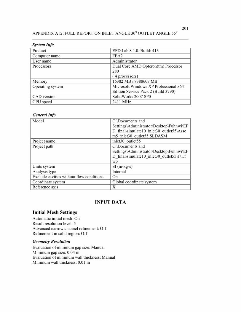
APPENDIX A12: FULL REPORT ON INLET ANGLE 300 OUTLET ANGLE 550201
System InfoProduct EFD.Lab 8 1.0. Build: 413Computer name FEA2User name AdministratorProcessors Dual Core AMD Opteron(tm) Processor
280( 4 processors)
Memory 16382 MB / 8388607 MBOperating system Microsoft Windows XP Professional x64
Edition Service Pack 2 (Build 3790)CAD version SolidWorks 2007 SP0CPU speed 2411 MHz
General InfoModel C:\Documents and
Settings\Administrator\Desktop\Fuhnwi\EFD_final\simulate10_inlet30_outlet55\Assem5_inlet30_outlet55.SLDASM
Project name inlet30_outlet55Project path C:\Documents and
Settings\Administrator\Desktop\Fuhnwi\EFD_final\simulate10_inlet30_outlet55\1\1.fwp
Units system SI (m-kg-s)Analysis type InternalExclude cavities without flow conditions OnCoordinate system Global coordinate systemReference axis X
INPUT DATA
Initial Mesh SettingsAutomatic initial mesh: OnResult resolution level: 5Advanced narrow channel refinement: OffRefinement in solid region: Off
Geometry ResolutionEvaluation of minimum gap size: ManualMinimum gap size: 0.04 mEvaluation of minimum wall thickness: ManualMinimum wall thickness: 0.01 m

APPENDIX A12: FULL REPORT ON INLET ANGLE 300 OUTLET ANGLE 550202
Computational Domain
SizeX min -0.0514326445 mX max 0.0447593555 mY min -0.0483066476 mY max 0.0478853524 mZ min 0.00188716267 mZ max 0.0185204128 m
Boundary Conditions2D plane flow NoneAt X min DefaultAt X max DefaultAt Y min DefaultAt Y max DefaultAt Z min DefaultAt Z max Default
Physical FeaturesHeat conduction in solids: OffTime dependent: OffGravitational effects: OffFlow type: Laminar onlyCavitation: OffHigh Mach number flow: OffDefault roughness: 0 micrometer
Rotating Reference FrameAxis of coordinate system ZVelocity 209.43951 m/s
Default wall conditions: Adiabatic wall
Initial ConditionsThermodynamic parameters Static Pressure: 101325 Pa
Temperature: 293.2 KVelocity parameters Velocity vector
Velocity in X direction: 0 m/sVelocity in Y direction: 0 m/sVelocity in Z direction: 0 m/sRelative to rotating frame: Off

APPENDIX A12: FULL REPORT ON INLET ANGLE 300 OUTLET ANGLE 550203
Material Settings
FluidsWater
Boundary Conditionsstator WallType Real wallFaces Face <1 cover5-1@>
Face <1 cover5-1@>Face <1 cover5-1@>
Coordinate system Global coordinate systemReference axis X
Inlet Volume Flow 1Type Inlet Volume FlowFaces Face <1 cover5-1@>Coordinate system Face Coordinate SystemReference axis XFlow parameters Flow vectors direction: Normal to face
Volume flow rate normal to face: 0.3 m^3/sRelative to rotating frame: NoFully developed flow: NoInlet profile: 0
Thermodynamic parameters Temperature: 293.2 K
Environment Pressure 1Type Environment PressureFaces Face <1 cover5-1@>Coordinate system Global coordinate systemReference axis XThermodynamic parameters Environment pressure: 101325 Pa
Temperature: 293.2 K
Goals
Global GoalsGG Z - Component of TorqueType Global GoalGoal type Z - Component of TorqueCoordinate system Global coordinate systemUse in convergence On

APPENDIX A12: FULL REPORT ON INLET ANGLE 300 OUTLET ANGLE 550204
Surface GoalsSG Z - Component of Torque at statorType Surface GoalGoal type Z - Component of TorqueFaces Face<1>@cover5-1
Face<2>@cover5-1Face<3>@cover5-1
Coordinate system Global coordinate systemUse in convergence On
SG Mass Flow Rate at outletType Surface GoalGoal type Mass Flow RateFaces Face<2>@cover5-1Coordinate system Global coordinate systemUse in convergence On
SG Av Static Pressure at inletType Surface GoalGoal type Static PressureCalculate Average valueFaces Face<2>@cover5-1Coordinate system Global coordinate systemUse in convergence On
SG Bulk Av Static Pressure at impeller outletType Surface GoalGoal type Static PressureCalculate Average valueFaces Face<2>@measure5-1Coordinate system Global coordinate systemUse in convergence On
SG Mass Flow Rate at inletType Surface GoalGoal type Mass Flow RateFaces Face<5>@cover5-1Coordinate system Global coordinate systemUse in convergence On
Equation GoalsPresure DropType Equation GoalFormula SG Av Static Pressure at inlet-SG Bulk Av

APPENDIX A12: FULL REPORT ON INLET ANGLE 300 OUTLET ANGLE 550205
Static Pressure at impeller outletDimensionality Pressure & stressUse in convergence On
Torque on impellerType Equation GoalFormula GG Z - Component of Torque -SG Z -
Component of Torque at statorDimensionality TorqueUse in convergence On
EfficiencyType Equation GoalFormula Presure Drop*{Inlet Volume Flow
1:Volume flow rate normal to face:3.000e-001}/209.44/Torque on impeller
Dimensionality No unitsUse in convergence On
Component Control InfoDisabled components: Extrude1@measure5-1@Assem5_inlet30_outlet55
Calculation Control Options
Finish ConditionsFinish conditions If one is satisfiedMaximum travels 4Goals convergence Analysis interval: 0.5
Solver RefinementRefinement: Disabled
Results SavingSave before refinement On
Advanced Control OptionsFlow FreezingFlow freezing strategy Disabled

APPENDIX A12: FULL REPORT ON INLET ANGLE 300 OUTLET ANGLE 550206
RESULTS
General InfoIterations: 129CPU time: 585 s
LogMesh generation started 20:54:45 , Feb 20Mesh generation normally finished 20:54:52 , Feb 20Preparing data for calculation 20:54:57 , Feb 20Calculation started 0 20:55:01 , Feb 20Calculation has converged since thefollowing criteria are satisfied: 128
21:04:45 , Feb 20
Goals are converged 128Calculation finished 129 21:04:50 , Feb 20
Warnings: Negative pressure Minimum pressure=-1.16412e+008 Pa; dV/V=0.499466
A vortex crosses the pressure opening Boundary Condition : Environment Pressure1 ; Inlet flow/outlet flow=0.0824577
Calculation Mesh
Basic Mesh DimensionsNumber of cells in X 40Number of cells in Y 40Number of cells in Z 6
Number Of CellsTotal cells 49738Fluid cells 22217Solid cells 11374Partial cells 16147Irregular cells 0Trimmed cells 42
Maximum refinement level: 1
GoalsName Unit Value Progress Use in
convergenDelta Criteria

APPENDIX A12: FULL REPORT ON INLET ANGLE 300 OUTLET ANGLE 550207
ceGG Z -Component ofTorque
N*m 3503.83 100 On 29.5377437
30.025117
SG Z -Component ofTorque atstator
N*m -2.16163 100 On 0.559309985
0.595085581
SG MassFlow Rateat outlet
kg/s -299.268 100 On 0.00189396535
0.299268412
SG AvStaticPressure atinlet
Pa 1.33764e+008
100 On 1283574.07
2072918.53
SG BulkAv StaticPressure atimpelleroutlet
Pa -3.89871e+006
100 On 206094.954
354814.865
SG MassFlow Rateat inlet
kg/s 299.269 100 On 0 0.299268522
Torque onimpeller
N*m 3505.99 100 On 28.4206756
29.8007646
PresureDrop
Pa 1.37662e+008
100 On 1323501.36
1949021.47
Efficiency 56.2427 100 On 0.0929482693
0.362407826
Min/Max TableName Minimum MaximumPressure [Pa] -1.16412e+008 1.91696e+008Temperature [K] 237.43 300.695Density [kg/m^3] 995.593 1001.3Velocity [m/s] 0 876.779X-velocity [m/s] -576.48 574.177Y-velocity [m/s] -569.688 573.12Z-velocity [m/s] -757.069 468.916Heat Transfer Coefficient[W/m^2/K]
0 0
Shear Stress [Pa] 1.08593e-005 721757Surface Heat Flux [W/m^2] 0 0

APPENDIX A12: FULL REPORT ON INLET ANGLE 300 OUTLET ANGLE 550208
Water Mass Fraction [ ] 1 1Water Volume Fraction [ ] 1 1Fluid Temperature [K] 237.43 300.695Velocity RRF [m/s] 0 877.203X-velocity RRF [m/s] -582.946 577.28Y-velocity RRF [m/s] -571.382 577.974Z-velocity RRF [m/s] -757.069 468.916
Engineering Database
Liquids
WaterPath: Liquid FW DefinedDensity
0
200
400
600
800
1000
1200
0 100 200 300 400 500 600Temperature[K]
Den
sity
[kg/
m^3
]
Dynamic viscosity
0
0.0002
0.0004
0.0006
0.0008
0.001
0.0012
0.0014
0.0016
0.0018
0.002
0 100 200 300 400 500 600Temperature[K]
Dyn
amic
vis
cosi
ty[P
a*s]

APPENDIX A12: FULL REPORT ON INLET ANGLE 300 OUTLET ANGLE 550209
Specific heat (Cp)
4100
4200
4300
4400
4500
4600
4700
4800
4900
0 100 200 300 400 500 600Temperature[K]
Spec
ific
heat
(Cp)
[J/(k
g*K
)]
Thermal conductivity
0
0.1
0.2
0.3
0.4
0.5
0.6
0.7
0.8
0 100 200 300 400 500 600Temperature[K]
Ther
mal
con
duct
ivity
[W/(m
*K)]

APPENDIX A13: FM21 LABORATORY RESULTS210
SampleNumber
OrificeDifferentialPressure
dPo[kPa]
Pump 1DifferentialPressure
dPp1[kPa]
Pump 2DifferentialPressure
dPp2[kPa]
Motor1
Speed
n1[Hz]
Motor2
Speed
n2[Hz]
Motor1
InputPower
Pe1[W]
Motor2
InputPower
Pe2[W]
WaterTemperature
Tw[°C]
OperatingMode
1 7.007 39.961 0.000 45 0 289.79 0.00 41.0 Single2 6.887 39.854 0.322 44 0 284.42 0.00 41.2 Single3 6.836 40.605 0.107 44 0 277.59 0.00 41.5 Single4 6.870 41.895 0.000 44 0 281.49 0.00 41.8 Single5 6.853 42.109 0.322 44 0 283.20 0.00 41.6 Single6 6.768 42.324 0.752 44 0 283.45 0.00 41.9 Single7 6.648 42.969 0.752 44 0 280.52 0.00 42.1 Single8 6.750 42.646 0.537 44 0 285.89 0.00 42.3 Single9 6.597 43.506 0.645 44 0 282.96 0.00 42.3 Single10 6.648 43.828 0.000 44 0 278.81 0.00 42.5 Single11 6.699 43.828 0.000 44 0 282.23 0.00 42.7 Single12 6.648 44.150 0.000 44 0 280.76 0.00 43.0 Single13 6.682 43.506 0.322 44 0 279.30 0.00 43.3 Single14 6.631 44.473 0.000 44 0 284.67 0.00 43.2 Single15 6.545 44.902 0.000 44 0 283.94 0.00 43.6 Single16 6.511 44.473 0.000 44 0 286.87 0.00 43.6 Single17 6.477 44.580 0.215 44 0 281.25 0.00 43.9 Single18 6.443 44.365 0.752 44 0 284.18 0.00 43.8 Single19 6.443 44.795 0.430 44 0 283.69 0.00 44.0 Single20 6.426 44.473 0.645 44 0 272.46 0.00 44.2 Single21 6.511 44.365 0.537 44 0 280.03 0.00 44.4 Single22 6.306 44.043 0.537 44 0 277.10 0.00 44.7 Single23 6.426 44.795 0.107 44 0 273.68 0.00 44.7 Single24 6.460 44.580 0.215 44 0 283.20 0.00 44.8 Single25 6.511 44.150 0.000 44 0 282.71 0.00 45.0 Single26 6.426 44.365 0.000 44 0 275.39 0.00 45.3 Single27 6.357 44.580 0.215 44 0 282.23 0.00 45.4 Single28 6.357 44.473 0.107 44 0 283.45 0.00 45.4 Single29 6.340 44.473 0.000 44 0 276.37 0.00 45.7 Single30 6.357 44.043 0.107 44 0 277.34 0.00 45.7 Single31 6.306 44.365 0.000 44 0 285.89 0.00 45.8 Single32 6.238 44.365 0.215 44 0 283.45 0.00 46.1 Single33 6.238 44.580 0.645 44 0 279.30 0.00 46.2 Single34 6.152 44.473 0.430 44 0 281.25 0.00 46.4 Single35 6.169 44.365 0.000 44 0 281.98 0.00 46.4 Single36 7.485 44.795 0.107 44 0 285.16 0.00 46.6 Single37 7.639 44.365 0.107 44 0 281.01 0.00 46.7 Single38 7.793 44.150 0.537 44 0 278.08 0.00 46.8 Single39 7.878 44.043 0.107 44 0 273.44 0.00 46.9 Single40 8.101 44.580 0.430 44 0 286.13 0.00 47.2 Single41 8.101 44.365 0.000 44 0 282.71 0.00 47.1 Single42 8.152 44.795 0.000 44 0 282.71 0.00 47.4 Single43 8.271 44.795 0.000 44 0 274.17 0.00 47.4 Single44 8.306 44.258 0.430 44 0 283.94 0.00 47.6 Single45 8.425 44.473 0.215 44 0 289.31 0.00 47.8 Single46 8.408 44.580 0.645 44 0 274.17 0.00 47.8 Single47 8.477 44.473 0.322 44 0 281.01 0.00 47.9 Single48 8.528 43.828 0.107 44 0 281.25 0.00 47.9 Single49 8.613 44.473 0.107 44 0 276.61 0.00 48.2 Single50 6.563 45.654 1.182 44 0 292.24 0.00 47.9 Single

APPENDIX A13: FM21 LABORATORY RESULTS211
SampleNumber
OrificeDifferentialPressure
dPo[kPa]
Pump 1DifferentialPressure
dPp1[kPa]
Pump 2DifferentialPressure
dPp2[kPa]
Motor1
Speed
n1[Hz]
Motor2
Speed
n2[Hz]
Motor1
InputPower
Pe1[W]
Motor2
InputPower
Pe2[W]
WaterTemperature
Tw[°C]
OperatingMode
51 6.460 45.332 3.545 44 0 281.01 0.00 47.8 Single52 6.323 45.332 3.330 44 0 281.98 0.00 48.0 Single53 6.289 45.332 3.438 44 0 283.20 0.00 48.1 Single54 6.204 45.117 3.223 44 0 278.32 0.00 48.2 Single55 6.375 45.225 3.223 44 0 279.30 0.00 48.2 Single56 6.306 45.010 3.330 44 0 279.54 0.00 48.3 Single57 6.221 45.439 2.900 44 0 280.52 0.00 48.4 Single58 6.238 45.225 2.900 44 0 280.76 0.00 48.5 Single59 6.204 45.225 2.900 44 0 285.64 0.00 48.7 Single60 6.221 44.902 3.545 44 0 276.12 0.00 48.7 Single61 6.272 45.332 3.008 44 0 276.86 0.00 48.9 Single62 6.255 45.225 3.545 44 0 281.01 0.00 48.7 Single63 6.169 45.439 2.578 44 0 281.98 0.00 49.0 Single64 6.289 45.010 3.438 44 0 280.76 0.00 49.0 Single65 6.187 44.795 3.223 44 0 279.54 0.00 49.0 Single66 6.187 44.902 2.793 44 0 286.38 0.00 49.2 Single67 6.221 44.795 3.330 44 0 282.96 0.00 49.2 Single68 6.204 44.795 3.330 44 0 284.91 0.00 49.3 Single69 6.255 44.795 3.438 44 0 282.71 0.00 49.4 Single70 6.255 44.795 3.330 44 0 280.27 0.00 49.4 Single71 6.135 45.439 2.686 44 0 282.23 0.00 49.7 Single72 6.152 44.902 2.578 44 0 287.11 0.00 49.7 Single73 6.204 45.225 3.008 44 0 280.03 0.00 49.9 Single74 6.084 45.117 2.793 44 0 283.45 0.00 49.8 Single75 6.118 45.117 3.545 44 0 285.40 0.00 50.1 Single76 6.084 45.117 3.008 44 0 282.71 0.00 50.0 Single77 6.135 44.902 3.115 44 0 276.61 0.00 50.0 Single78 6.169 45.010 3.545 44 0 280.52 0.00 50.2 Single79 6.135 44.580 3.115 44 0 281.74 0.00 50.1 Single80 6.204 44.580 3.438 44 0 278.81 0.00 50.2 Single81 6.118 44.688 2.686 44 0 279.54 0.00 50.3 Single82 6.084 45.225 2.900 44 0 273.68 0.00 50.4 Single83 6.016 44.902 3.115 44 0 282.47 0.00 50.5 Single84 6.016 44.795 3.652 44 0 276.37 0.00 50.6 Single85 6.050 44.688 2.793 44 0 278.81 0.00 50.7 Single86 6.016 44.580 2.900 44 0 278.56 0.00 50.8 Single87 5.981 44.580 3.223 44 0 283.94 0.00 50.7 Single88 6.101 44.580 3.330 44 0 278.56 0.00 50.8 Single89 5.999 44.902 3.545 44 0 273.68 0.00 51.0 Single90 5.999 44.795 2.900 44 0 273.68 0.00 51.1 Single91 6.016 44.365 3.438 44 0 277.83 0.00 50.9 Single92 6.101 44.580 3.438 44 0 277.83 0.00 51.0 Single93 5.964 44.258 3.223 44 0 278.08 0.00 51.1 Single94 6.033 44.688 3.223 44 0 278.81 0.00 51.2 Single95 5.981 44.580 2.900 44 0 272.46 0.00 51.3 Single96 5.981 44.258 3.115 44 0 284.67 0.00 51.2 Single97 6.033 44.580 3.223 44 0 278.56 0.00 51.3 Single98 6.033 45.010 3.223 44 0 278.32 0.00 51.3 Single99 5.947 44.688 3.223 44 0 281.25 0.00 51.5 Single
100 5.930 44.902 3.330 44 0 282.71 0.00 51.6 Single

APPENDIX A14: FM21 LABORATORY RESULTS
212
Sample
Number
Densityof
waterrho
[kg/m³]
Orifice
DischargeCoefficient
Cd
Volume
Flowrate
Qv[dm³/
s]
Pump 1
InletVeloc
ityV1
[m/s]
Pump 1
Outlet
VelocityV2
[m/s]
Pump 2
InletVeloc
ityV3
[m/s]
Pump 2
Outlet
VelocityV4
[m/s]
Pump 1
TotalHead
H1[m]
Pump 2
TotalHead
H2[m]
CombinedTotalHead
Ht[m]
Pump 1
Power
OutputP1[W]
Pump 2
Power
OutputP2[W]
CombinedPowe
rOutp
utPt
[W]
Pump 1
Efficiency
E1[%]
Pump 2
Efficiency
E2[%]
Overall
Efficiency
Egr[%]
1 991.9 0.610 1.037 3.64 3.64 3.64 3.64 4.15 0.05 4.15 41.9 0.5 41.9 14.5 0.0 14.52 991.8 0.610 1.028 3.61 3.61 3.61 3.61 4.14 0.08 4.14 41.5 0.8 41.5 14.6 0.0 14.63 991.7 0.610 1.025 3.60 3.60 3.60 3.60 4.22 0.06 4.22 42.1 0.6 42.1 15.2 0.0 15.24 991.6 0.610 1.027 3.60 3.60 3.60 3.60 4.35 0.05 4.35 43.5 0.5 43.5 15.5 0.0 15.55 991.7 0.610 1.026 3.60 3.60 3.60 3.60 4.38 0.08 4.38 43.7 0.8 43.7 15.4 0.0 15.46 991.6 0.610 1.020 3.58 3.58 3.58 3.58 4.40 0.13 4.40 43.6 1.2 43.6 15.4 0.0 15.47 991.5 0.610 1.011 3.55 3.55 3.55 3.55 4.47 0.13 4.47 43.9 1.2 43.9 15.6 0.0 15.68 991.4 0.610 1.018 3.57 3.57 3.57 3.57 4.43 0.10 4.43 43.9 1.0 43.9 15.4 0.0 15.49 991.4 0.610 1.007 3.53 3.53 3.53 3.53 4.52 0.11 4.52 44.3 1.1 44.3 15.6 0.0 15.610 991.3 0.610 1.011 3.55 3.55 3.55 3.55 4.55 0.05 4.55 44.8 0.5 44.8 16.1 0.0 16.111 991.3 0.610 1.015 3.56 3.56 3.56 3.56 4.56 0.05 4.56 44.9 0.5 44.9 15.9 0.0 15.912 991.1 0.610 1.011 3.55 3.55 3.55 3.55 4.59 0.05 4.59 45.1 0.5 45.1 16.1 0.0 16.113 991.0 0.610 1.013 3.56 3.56 3.56 3.56 4.52 0.08 4.52 44.6 0.8 44.6 16.0 0.0 16.014 991.1 0.610 1.009 3.54 3.54 3.54 3.54 4.62 0.05 4.62 45.4 0.5 45.4 15.9 0.0 15.915 990.9 0.610 1.003 3.52 3.52 3.52 3.52 4.67 0.05 4.67 45.5 0.5 45.5 16.0 0.0 16.016 990.9 0.610 1.000 3.51 3.51 3.51 3.51 4.62 0.05 4.62 45.0 0.5 45.0 15.7 0.0 15.717 990.8 0.610 0.998 3.50 3.50 3.50 3.50 4.63 0.07 4.63 44.9 0.7 44.9 16.0 0.0 16.018 990.8 0.610 0.995 3.49 3.49 3.49 3.49 4.61 0.13 4.61 44.6 1.2 44.6 15.7 0.0 15.719 990.7 0.610 0.995 3.49 3.49 3.49 3.49 4.66 0.09 4.66 45.0 0.9 45.0 15.9 0.0 15.920 990.7 0.610 0.994 3.49 3.49 3.49 3.49 4.62 0.11 4.62 44.7 1.1 44.7 16.4 0.0 16.421 990.6 0.610 1.001 3.51 3.51 3.51 3.51 4.61 0.10 4.61 44.9 1.0 44.9 16.0 0.0 16.022 990.5 0.610 0.985 3.46 3.46 3.46 3.46 4.58 0.10 4.58 43.8 1.0 43.8 15.8 0.0 15.823 990.4 0.610 0.994 3.49 3.49 3.49 3.49 4.66 0.06 4.66 45.0 0.6 45.0 16.4 0.0 16.424 990.4 0.610 0.997 3.50 3.50 3.50 3.50 4.64 0.07 4.64 44.9 0.7 44.9 15.9 0.0 15.925 990.3 0.610 1.001 3.51 3.51 3.51 3.51 4.59 0.05 4.59 44.6 0.5 44.6 15.8 0.0 15.826 990.2 0.610 0.994 3.49 3.49 3.49 3.49 4.62 0.05 4.62 44.6 0.5 44.6 16.2 0.0 16.227 990.2 0.610 0.989 3.47 3.47 3.47 3.47 4.64 0.07 4.64 44.5 0.7 44.5 15.8 0.0 15.828 990.1 0.610 0.989 3.47 3.47 3.47 3.47 4.63 0.06 4.63 44.4 0.6 44.4 15.7 0.0 15.729 990.0 0.610 0.988 3.47 3.47 3.47 3.47 4.63 0.05 4.63 44.4 0.5 44.4 16.1 0.0 16.130 990.0 0.610 0.989 3.47 3.47 3.47 3.47 4.58 0.06 4.58 44.0 0.6 44.0 15.9 0.0 15.931 990.0 0.610 0.985 3.46 3.46 3.46 3.46 4.62 0.05 4.62 44.2 0.5 44.2 15.4 0.0 15.432 989.9 0.610 0.980 3.44 3.44 3.44 3.44 4.62 0.07 4.62 43.9 0.7 43.9 15.5 0.0 15.533 989.8 0.610 0.980 3.44 3.44 3.44 3.44 4.64 0.11 4.64 44.1 1.1 44.1 15.8 0.0 15.834 989.7 0.610 0.973 3.41 3.41 3.41 3.41 4.63 0.09 4.63 43.7 0.9 43.7 15.5 0.0 15.535 989.7 0.610 0.974 3.42 3.42 3.42 3.42 4.62 0.05 4.62 43.7 0.5 43.7 15.5 0.0 15.536 989.7 0.610 1.073 3.77 3.77 3.77 3.77 4.66 0.06 4.66 48.6 0.6 48.6 17.0 0.0 17.037 989.6 0.610 1.084 3.80 3.80 3.80 3.80 4.62 0.06 4.62 48.6 0.6 48.6 17.3 0.0 17.338 989.6 0.610 1.095 3.84 3.84 3.84 3.84 4.60 0.10 4.60 48.9 1.1 48.9 17.6 0.0 17.639 989.5 0.610 1.101 3.86 3.86 3.86 3.86 4.59 0.06 4.59 49.0 0.6 49.0 17.9 0.0 17.940 989.4 0.610 1.117 3.92 3.92 3.92 3.92 4.64 0.09 4.64 50.3 1.0 50.3 17.6 0.0 17.641 989.4 0.610 1.117 3.92 3.92 3.92 3.92 4.62 0.05 4.62 50.1 0.5 50.1 17.7 0.0 17.742 989.3 0.610 1.120 3.93 3.93 3.93 3.93 4.66 0.05 4.66 50.7 0.5 50.7 17.9 0.0 17.943 989.3 0.610 1.128 3.96 3.96 3.96 3.96 4.66 0.05 4.66 51.1 0.5 51.1 18.6 0.0 18.644 989.2 0.610 1.131 3.97 3.97 3.97 3.97 4.61 0.09 4.61 50.6 1.0 50.6 17.8 0.0 17.845 989.1 0.610 1.139 4.00 4.00 4.00 4.00 4.63 0.07 4.63 51.2 0.8 51.2 17.7 0.0 17.746 989.1 0.610 1.138 3.99 3.99 3.99 3.99 4.64 0.11 4.64 51.3 1.3 51.3 18.7 0.0 18.747 989.1 0.610 1.142 4.01 4.01 4.01 4.01 4.63 0.08 4.63 51.3 0.9 51.3 18.3 0.0 18.348 989.1 0.610 1.146 4.02 4.02 4.02 4.02 4.57 0.06 4.57 50.8 0.7 50.8 18.0 0.0 18.049 988.9 0.610 1.152 4.04 4.04 4.04 4.04 4.63 0.06 4.63 51.8 0.7 51.8 18.7 0.0 18.750 989.1 0.610 1.005 3.53 3.53 3.53 3.53 4.75 0.17 4.75 46.4 1.7 46.4 15.9 0.0 15.9

APPENDIX A14: FM21 LABORATORY RESULTS
213
Sample
Number
Densityof
waterrho
[kg/m³]
Orifice
DischargeCoefficient
Cd
Volume
Flowrate
Qv[dm³/
s]
Pump 1
InletVeloc
ityV1
[m/s]
Pump 1
Outlet
VelocityV2
[m/s]
Pump 2
InletVeloc
ityV3
[m/s]
Pump 2
Outlet
VelocityV4
[m/s]
Pump 1
TotalHead
H1[m]
Pump 2
TotalHead
H2[m]
CombinedTotalHead
Ht[m]
Pump 1
Power
OutputP1[W]
Pump 2
Power
OutputP2[W]
CombinedPowe
rOutp
utPt
[W]
Pump 1
Efficiency
E1[%]
Pump 2
Efficiency
E2[%]
Overall
Efficiency
Egr[%]
51 989.1 0.610 0.997 3.50 3.50 3.50 3.50 4.72 0.41 4.72 45.7 4.0 45.7 16.3 0.0 16.352 989.0 0.610 0.987 3.46 3.46 3.46 3.46 4.72 0.39 4.72 45.2 3.7 45.2 16.0 0.0 16.053 989.0 0.610 0.984 3.45 3.45 3.45 3.45 4.72 0.40 4.72 45.1 3.8 45.1 15.9 0.0 15.954 989.0 0.610 0.977 3.43 3.43 3.43 3.43 4.70 0.38 4.70 44.6 3.6 44.6 16.0 0.0 16.055 989.0 0.610 0.991 3.48 3.48 3.48 3.48 4.71 0.38 4.71 45.3 3.7 45.3 16.2 0.0 16.256 988.9 0.610 0.986 3.46 3.46 3.46 3.46 4.69 0.39 4.69 44.8 3.7 44.8 16.0 0.0 16.057 988.9 0.610 0.979 3.43 3.43 3.43 3.43 4.73 0.35 4.73 44.9 3.3 44.9 16.0 0.0 16.058 988.8 0.610 0.980 3.44 3.44 3.44 3.44 4.71 0.35 4.71 44.8 3.3 44.8 16.0 0.0 16.059 988.8 0.610 0.978 3.43 3.43 3.43 3.43 4.71 0.35 4.71 44.7 3.3 44.7 15.6 0.0 15.660 988.7 0.610 0.979 3.43 3.43 3.43 3.43 4.68 0.41 4.68 44.4 3.9 44.4 16.1 0.0 16.161 988.6 0.610 0.983 3.45 3.45 3.45 3.45 4.72 0.36 4.72 45.0 3.4 45.0 16.3 0.0 16.362 988.7 0.610 0.982 3.44 3.44 3.44 3.44 4.71 0.41 4.71 44.8 3.9 44.8 16.0 0.0 16.063 988.6 0.610 0.975 3.42 3.42 3.42 3.42 4.73 0.31 4.73 44.8 3.0 44.8 15.9 0.0 15.964 988.6 0.610 0.984 3.45 3.45 3.45 3.45 4.69 0.40 4.69 44.8 3.8 44.8 15.9 0.0 15.965 988.6 0.610 0.976 3.43 3.43 3.43 3.43 4.67 0.38 4.67 44.2 3.6 44.2 15.8 0.0 15.866 988.5 0.610 0.976 3.43 3.43 3.43 3.43 4.68 0.34 4.68 44.3 3.2 44.3 15.5 0.0 15.567 988.5 0.610 0.979 3.44 3.44 3.44 3.44 4.67 0.39 4.67 44.3 3.7 44.3 15.7 0.0 15.768 988.5 0.610 0.978 3.43 3.43 3.43 3.43 4.67 0.39 4.67 44.3 3.7 44.3 15.5 0.0 15.569 988.4 0.610 0.982 3.44 3.44 3.44 3.44 4.67 0.40 4.67 44.4 3.8 44.4 15.7 0.0 15.770 988.4 0.610 0.982 3.44 3.44 3.44 3.44 4.67 0.39 4.67 44.4 3.7 44.4 15.9 0.0 15.971 988.3 0.610 0.972 3.41 3.41 3.41 3.41 4.73 0.33 4.73 44.6 3.1 44.6 15.8 0.0 15.872 988.3 0.610 0.974 3.42 3.42 3.42 3.42 4.68 0.31 4.68 44.2 3.0 44.2 15.4 0.0 15.473 988.2 0.610 0.978 3.43 3.43 3.43 3.43 4.71 0.36 4.71 44.7 3.4 44.7 16.0 0.0 16.074 988.2 0.610 0.968 3.40 3.40 3.40 3.40 4.70 0.34 4.70 44.1 3.2 44.1 15.6 0.0 15.675 988.1 0.610 0.971 3.41 3.41 3.41 3.41 4.70 0.41 4.70 44.3 3.9 44.3 15.5 0.0 15.576 988.2 0.610 0.968 3.40 3.40 3.40 3.40 4.70 0.36 4.70 44.1 3.4 44.1 15.6 0.0 15.677 988.1 0.610 0.972 3.41 3.41 3.41 3.41 4.68 0.37 4.68 44.1 3.5 44.1 15.9 0.0 15.978 988.0 0.610 0.975 3.42 3.42 3.42 3.42 4.69 0.41 4.69 44.3 3.9 44.3 15.8 0.0 15.879 988.1 0.610 0.972 3.41 3.41 3.41 3.41 4.65 0.37 4.65 43.8 3.5 43.8 15.5 0.0 15.580 988.1 0.610 0.978 3.43 3.43 3.43 3.43 4.65 0.40 4.65 44.0 3.8 44.0 15.8 0.0 15.881 988.0 0.610 0.971 3.41 3.41 3.41 3.41 4.66 0.33 4.66 43.9 3.1 43.9 15.7 0.0 15.782 988.0 0.610 0.968 3.40 3.40 3.40 3.40 4.71 0.35 4.71 44.2 3.3 44.2 16.2 0.0 16.283 987.9 0.610 0.963 3.38 3.38 3.38 3.38 4.68 0.37 4.68 43.7 3.4 43.7 15.5 0.0 15.584 987.9 0.610 0.963 3.38 3.38 3.38 3.38 4.67 0.42 4.67 43.6 4.0 43.6 15.8 0.0 15.885 987.8 0.610 0.966 3.39 3.39 3.39 3.39 4.66 0.34 4.66 43.6 3.1 43.6 15.6 0.0 15.686 987.8 0.610 0.963 3.38 3.38 3.38 3.38 4.65 0.35 4.65 43.4 3.2 43.4 15.6 0.0 15.687 987.8 0.610 0.960 3.37 3.37 3.37 3.37 4.65 0.38 4.65 43.3 3.5 43.3 15.2 0.0 15.288 987.8 0.610 0.970 3.40 3.40 3.40 3.40 4.65 0.39 4.65 43.7 3.7 43.7 15.7 0.0 15.789 987.7 0.610 0.962 3.37 3.37 3.37 3.37 4.68 0.41 4.68 43.6 3.9 43.6 15.9 0.0 15.990 987.7 0.610 0.962 3.37 3.37 3.37 3.37 4.67 0.35 4.67 43.5 3.2 43.5 15.9 0.0 15.991 987.7 0.610 0.963 3.38 3.38 3.38 3.38 4.63 0.40 4.63 43.2 3.8 43.2 15.5 0.0 15.592 987.7 0.610 0.970 3.40 3.40 3.40 3.40 4.65 0.40 4.65 43.7 3.8 43.7 15.7 0.0 15.793 987.7 0.610 0.959 3.37 3.37 3.37 3.37 4.62 0.38 4.62 42.9 3.5 42.9 15.4 0.0 15.494 987.6 0.610 0.965 3.38 3.38 3.38 3.38 4.66 0.38 4.66 43.6 3.6 43.6 15.6 0.0 15.695 987.5 0.610 0.960 3.37 3.37 3.37 3.37 4.65 0.35 4.65 43.3 3.2 43.3 15.9 0.0 15.996 987.6 0.610 0.960 3.37 3.37 3.37 3.37 4.62 0.37 4.62 43.0 3.4 43.0 15.1 0.0 15.197 987.6 0.610 0.965 3.38 3.38 3.38 3.38 4.65 0.38 4.65 43.4 3.6 43.4 15.6 0.0 15.698 987.5 0.610 0.965 3.38 3.38 3.38 3.38 4.69 0.38 4.69 43.9 3.6 43.9 15.8 0.0 15.899 987.5 0.610 0.958 3.36 3.36 3.36 3.36 4.66 0.38 4.66 43.2 3.5 43.2 15.4 0.0 15.4
100 987.4 0.610 0.956 3.36 3.36 3.36 3.36 4.68 0.39 4.68 43.4 3.6 43.4 15.3 0.0 15.3

APPENDIX A15: FULL REPORT ON INLET ANGLE 300 OUTLET ANGLE 300214
System InfoProduct EFD.Lab 8 1.0. Build: 413Computer name FEA2User name AdministratorProcessors Dual Core AMD Opteron(tm) Processor
280( 4 processors)
Memory 16382 MB / 8388607 MBOperating system Microsoft Windows XP Professional x64
Edition Service Pack 2 (Build 3790)CAD version SolidWorks 2007 SP0CPU speed 2411 MHz
General InfoModel C:\Documents and
Settings\Administrator\Desktop\Fuhnwi\EFD_final\simulate3-1_inlet30_outlet30\Assem3-1_inlet30_outlet3o.SLDASM
Project name Default (1)Project path C:\Documents and
Settings\Administrator\Desktop\Fuhnwi\EFD_final\simulate3-1_inlet30_outlet30\1\1.fwp
Units system SI (m-kg-s)Analysis type InternalExclude cavities without flow conditions OnCoordinate system Global coordinate systemReference axis X
INPUT DATA
Initial Mesh SettingsAutomatic initial mesh: OnResult resolution level: 5Advanced narrow channel refinement: OffRefinement in solid region: Off
Geometry ResolutionEvaluation of minimum gap size: ManualMinimum gap size: 0.04 mEvaluation of minimum wall thickness: ManualMinimum wall thickness: 0.01 m

APPENDIX A15: FULL REPORT ON INLET ANGLE 300 OUTLET ANGLE 300215
Computational Domain
SizeX min -0.0473342462 mX max 0.0488577538 mY min -0.0430765393 mY max 0.0531154607 mZ min -0.0038287647 mZ max 0.0128044854 m
Boundary Conditions2D plane flow NoneAt X min DefaultAt X max DefaultAt Y min DefaultAt Y max DefaultAt Z min DefaultAt Z max Default
Physical FeaturesHeat conduction in solids: OffTime dependent: OffGravitational effects: OffFlow type: Turbulent onlyCavitation: OffHigh Mach number flow: OffDefault roughness: 0 micrometer
Rotating Reference FrameAxis of coordinate system ZVelocity 282.74 m/s
Default wall conditions: Adiabatic wall
Initial ConditionsThermodynamic parameters Static Pressure: 101325 Pa
Temperature: 293.2 KVelocity parameters Velocity vector
Velocity in X direction: 0 m/sVelocity in Y direction: 0 m/sVelocity in Z direction: 0 m/sRelative to rotating frame: Off

APPENDIX A15: FULL REPORT ON INLET ANGLE 300 OUTLET ANGLE 300216
Material Settings
FluidsWater
Boundary ConditionsInlet Volume Flow 1Type Inlet Volume FlowFaces Face <1 cover3-2-1@>Coordinate system Face Coordinate SystemReference axis XFlow parameters Flow vectors direction: Normal to face
Volume flow rate normal to face: 0.00101m^3/sRelative to rotating frame: NoFully developed flow: NoInlet profile: 0
Thermodynamic parameters Temperature: 293.2 K
Environment Pressure 1Type Environment PressureFaces Face <1 cover3-2-1@>Coordinate system Global coordinate systemReference axis XThermodynamic parameters Environment pressure: 101325 Pa
Temperature: 293.2 K
stator Wall 1Type Real wallFaces Face <1 cover3-2-1@>
Face <1 cover3-2-1@>Face <1 cover3-2-1@>
Coordinate system Global coordinate systemReference axis X
Goals
Global GoalsGG Z - Component of Torque 1Type Global GoalGoal type Z - Component of TorqueCoordinate system Global coordinate systemUse in convergence On

APPENDIX A15: FULL REPORT ON INLET ANGLE 300 OUTLET ANGLE 300217
Surface GoalsSG Av Static Pressure _inletType Surface GoalGoal type Static PressureCalculate Average valueFaces Face<2>@cover3-2-1Coordinate system Global coordinate systemUse in convergence On
SG Mass Flow Rate_inletType Surface GoalGoal type Mass Flow RateFaces Face<1>@cover3-2-1Coordinate system Global coordinate systemUse in convergence On
SG Bulk Av Static Pressure _impeller outletType Surface GoalGoal type Static PressureCalculate Average valueFaces Face<2>@measure3-2-1Coordinate system Global coordinate systemUse in convergence On
SG Z - Component of Torque at statorType Surface GoalGoal type Z - Component of TorqueFaces Face<1>@cover3-2-1
Face<2>@cover3-2-1Face<3>@cover3-2-1
Coordinate system Global coordinate systemUse in convergence On
SG Mass Flow Rate _outletType Surface GoalGoal type Mass Flow RateFaces Face<2>@cover3-2-1Coordinate system Global coordinate systemUse in convergence On
Equation GoalsPressure dropType Equation GoalFormula SG Av Static Pressure _inlet-SG Bulk Av

APPENDIX A15: FULL REPORT ON INLET ANGLE 300 OUTLET ANGLE 300218
Static Pressure _impeller outletDimensionality Pressure & stressUse in convergence On
Torque on impellerType Equation GoalFormula GG Z - Component of Torque 1-SG Z -
Component of Torque at statorDimensionality TorqueUse in convergence On
EfficiencyType Equation GoalFormula Pressure drop*{Inlet Volume Flow
1:Volume flow rate normal to face:1.010e-003}/282.74/Torque on impeller
Dimensionality No unitsUse in convergence On
Component Control InfoDisabled components: Extrude1@measure3-2-1@Assem3-1_inlet30_outlet3o
Calculation Control Options
Finish ConditionsFinish conditions If one is satisfiedMaximum travels 4Goals convergence Analysis interval: 0.5
Solver RefinementRefinement: Disabled
Results SavingSave before refinement On
Advanced Control OptionsFlow FreezingFlow freezing strategy Disabled

APPENDIX A15: FULL REPORT ON INLET ANGLE 300 OUTLET ANGLE 300219
RESULTS
General InfoIterations: 295CPU time: 1570 s
LogMesh generation started 11:13:11 , Jul 21Mesh generation normally finished 11:13:17 , Jul 21Preparing data for calculation 11:13:22 , Jul 21Calculation started 0 11:13:26 , Jul 21Calculation has converged since thefollowing criteria are satisfied: 294
11:39:42 , Jul 21
Max. travel is reached 294Calculation finished 295 11:39:51 , Jul 21
Warnings: A vortex crosses the pressure opening Boundary Condition : EnvironmentPressure 1 ; Inlet flow/outlet flow=0.605375
Calculation Mesh
Basic Mesh DimensionsNumber of cells in X 40Number of cells in Y 40Number of cells in Z 6
Number Of CellsTotal cells 49801Fluid cells 23112Solid cells 11113Partial cells 15576Irregular cells 0Trimmed cells 26
Maximum refinement level: 1
GoalsName Unit Value Progress Use in
convergence
Delta Criteria
GG Z -Component of
N*m -0.623886 100 On 0.0334975099
0.0986754648

APPENDIX A15: FULL REPORT ON INLET ANGLE 300 OUTLET ANGLE 300220
Torque 1SG AvStaticPressure_inlet
Pa 49512.4 100 On 651.88992 739.150748
SG MassFlowRate_inlet
kg/s 1.00754 100 On 0 0.00100753736
SG BulkAv StaticPressure_impelleroutlet
Pa 96843.8 100 On 177.339752
219.744227
SG Z -Component ofTorque atstator
N*m 0.0186791 100 On 0.00178236351
0.00224133559
SG MassFlow Rate_outlet
kg/s -1.00792 100 On 0.000222912072
0.00100792126
Torque onimpeller
N*m -0.642565 100 On 0.0350691759
0.0966930243
Pressuredrop
Pa -47331.4 100 On 370.632373
686.774081
Efficiency 0.263128 43.5 On 0.0157636393
0.00686383192
Min/Max TableName Minimum MaximumPressure [Pa] -11046.2 167971Temperature [K] 293.141 293.223Density [kg/m^3] 997.561 997.577Velocity [m/s] 0 23.3842X-velocity [m/s] -13.3343 10.3095Y-velocity [m/s] -22.911 11.9444Z-velocity [m/s] -7.11698 10.5381Heat Transfer Coefficient[W/m^2/K]
0 0
Shear Stress [Pa] 1.30718e-007 11549.6Surface Heat Flux [W/m^2] 0 0Water Mass Fraction [ ] 1 1Water Volume Fraction [ ] 1 1Fluid Temperature [K] 293.141 293.223

APPENDIX A15: FULL REPORT ON INLET ANGLE 300 OUTLET ANGLE 300221
Velocity RRF [m/s] 0 15.457X-velocity RRF [m/s] -11.6694 15.4561Y-velocity RRF [m/s] -13.6327 13.7425Z-velocity RRF [m/s] -7.11698 10.5381
Engineering Database
Liquids
WaterPath: Liquid FW DefinedDensity
0
200
400
600
800
1000
1200
0 100 200 300 400 500 600Temperature[K]
Den
sity
[kg/
m^3
]
Dynamic viscosity
0
0.0002
0.0004
0.0006
0.0008
0.001
0.0012
0.0014
0.0016
0.0018
0.002
0 100 200 300 400 500 600Temperature[K]
Dyn
amic
vis
cosi
ty[P
a*s]

APPENDIX A15: FULL REPORT ON INLET ANGLE 300 OUTLET ANGLE 300222
Specific heat (Cp)
4100
4200
4300
4400
4500
4600
4700
4800
4900
0 100 200 300 400 500 600Temperature[K]
Spec
ific
heat
(Cp)
[J/(k
g*K
)]
Thermal conductivity
0
0.1
0.2
0.3
0.4
0.5
0.6
0.7
0.8
0 100 200 300 400 500 600Temperature[K]
Ther
mal
con
duct
ivity
[W/(m
*K)]

APPENDIX A16: FULL REPORT ON INLET ANGLE 300 OUTLET ANGLE 350223
System InfoProduct EFD.Lab 8 1.0. Build: 413Computer name FEA2User name AdministratorProcessors Dual Core AMD Opteron(tm) Processor
280( 4 processors)
Memory 16382 MB / 8388607 MBOperating system Microsoft Windows XP Professional x64
Edition Service Pack 2 (Build 3790)CAD version SolidWorks 2007 SP0CPU speed 2411 MHz
General InfoModel C:\Documents and
Settings\Administrator\Desktop\Fuhnwi\EFD_final\simulate2_inlet30_outlet35\Assem3-1_inlet30_outlet35.SLDASM
Project name inlet30_outlet35Project path C:\Documents and
Settings\Administrator\Desktop\Fuhnwi\EFD_final\simulate2_inlet30_outlet35\1\1.fwp
Units system SI (m-kg-s)Analysis type InternalExclude cavities without flow conditions OnCoordinate system Global coordinate systemReference axis X
INPUT DATA
Initial Mesh SettingsAutomatic initial mesh: OnResult resolution level: 5Advanced narrow channel refinement: OffRefinement in solid region: Off
Geometry ResolutionEvaluation of minimum gap size: ManualMinimum gap size: 0.04 mEvaluation of minimum wall thickness: ManualMinimum wall thickness: 0.01 m

APPENDIX A16: FULL REPORT ON INLET ANGLE 300 OUTLET ANGLE 350224
Computational Domain
SizeX min -0.0473342462 mX max 0.0488577538 mY min -0.0430765393 mY max 0.0531154607 mZ min -0.0038287647 mZ max 0.0128044854 m
Boundary Conditions2D plane flow NoneAt X min DefaultAt X max DefaultAt Y min DefaultAt Y max DefaultAt Z min DefaultAt Z max Default
Physical FeaturesHeat conduction in solids: OffTime dependent: OffGravitational effects: OffFlow type: Laminar onlyCavitation: OffHigh Mach number flow: OffDefault roughness: 0 micrometer
Rotating Reference FrameAxis of coordinate system ZVelocity 282.74 m/s
Default wall conditions: Adiabatic wall
Initial ConditionsThermodynamic parameters Static Pressure: 101325 Pa
Temperature: 293.2 KVelocity parameters Velocity vector
Velocity in X direction: 0 m/sVelocity in Y direction: 0 m/sVelocity in Z direction: 0 m/sRelative to rotating frame: Off

APPENDIX A16: FULL REPORT ON INLET ANGLE 300 OUTLET ANGLE 350225
Material Settings
FluidsWater
Boundary ConditionsEnvironment Pressure 1Type Environment PressureFaces Face <1 >Coordinate system Global coordinate systemReference axis XThermodynamic parameters Environment pressure: 101325 Pa
Temperature: 293.2 K
stator wallsType Real wallFaces Face <1 >
Face <1 >Face <1 >
Coordinate system Global coordinate systemReference axis X
Inlet Volume Flow 1Type Inlet Volume FlowFaces Face <1 >Coordinate system Face Coordinate SystemReference axis XFlow parameters Flow vectors direction: Normal to face
Volume flow rate normal to face: 0.00101m^3/sRelative to rotating frame: NoFully developed flow: NoInlet profile: 0
Thermodynamic parameters Temperature: 293.2 K
Goals
Global GoalsGG Z - Component of TorqueType Global GoalGoal type Z - Component of TorqueCoordinate system Global coordinate systemUse in convergence On

APPENDIX A16: FULL REPORT ON INLET ANGLE 300 OUTLET ANGLE 350226
Surface GoalsSG Bulk Av Static Pressure at impeller outletType Surface GoalGoal type Static PressureCalculate Average valueFaces Face<1>@cover3-1-1
Face<2>@measure3-1-1Coordinate system Global coordinate systemUse in convergence On
SG Mass Flow Rate at outletType Surface GoalGoal type Mass Flow RateFaces Face<2>@cover3-1-1Coordinate system Global coordinate systemUse in convergence On
SG Z - Component of Torque at statorType Surface GoalGoal type Z - Component of TorqueFaces Face<1>@cover3-1-1
Face<2>@cover3-1-1Face<3>@cover3-1-1
Coordinate system Global coordinate systemUse in convergence On
SG Mass Flow Rate at inletType Surface GoalGoal type Mass Flow RateFaces Face<1>@cover3-1-1Coordinate system Global coordinate systemUse in convergence On
SG Av Static Pressure at inletType Surface GoalGoal type Static PressureCalculate Average valueFaces Face<1>@cover3-1-1Coordinate system Global coordinate systemUse in convergence On
Equation GoalsPressure dropType Equation Goal
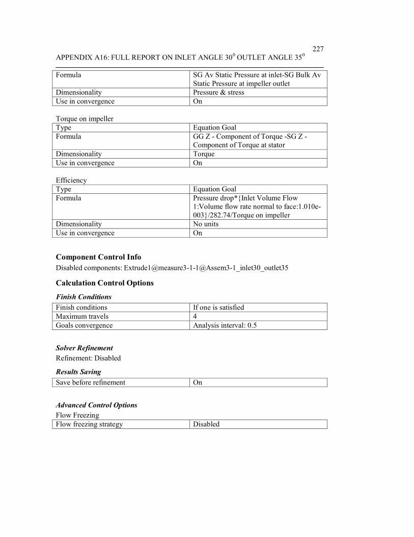
APPENDIX A16: FULL REPORT ON INLET ANGLE 300 OUTLET ANGLE 350227
Formula SG Av Static Pressure at inlet-SG Bulk AvStatic Pressure at impeller outlet
Dimensionality Pressure & stressUse in convergence On
Torque on impellerType Equation GoalFormula GG Z - Component of Torque -SG Z -
Component of Torque at statorDimensionality TorqueUse in convergence On
EfficiencyType Equation GoalFormula Pressure drop*{Inlet Volume Flow
1:Volume flow rate normal to face:1.010e-003}/282.74/Torque on impeller
Dimensionality No unitsUse in convergence On
Component Control InfoDisabled components: Extrude1@measure3-1-1@Assem3-1_inlet30_outlet35
Calculation Control Options
Finish ConditionsFinish conditions If one is satisfiedMaximum travels 4Goals convergence Analysis interval: 0.5
Solver RefinementRefinement: Disabled
Results SavingSave before refinement On
Advanced Control OptionsFlow FreezingFlow freezing strategy Disabled

APPENDIX A16: FULL REPORT ON INLET ANGLE 300 OUTLET ANGLE 350228
RESULTS
General InfoIterations: 295CPU time: 1292 s
LogMesh generation started 12:08:09 , Jun 24Mesh generation normally finished 12:08:14 , Jun 24Preparing data for calculation 12:18:11 , Jul 21Calculation started 0 12:18:16 , Jul 21Calculation has converged since thefollowing criteria are satisfied: 294
12:39:53 , Jul 21
Max. travel is reached 294Calculation finished 295 12:39:57 , Jul 21
Warnings: A vortex crosses the pressure opening Boundary Condition : EnvironmentPressure 1 ; Inlet flow/outlet flow=0.586491
Calculation Mesh
Basic Mesh DimensionsNumber of cells in X 40Number of cells in Y 40Number of cells in Z 6
Number Of CellsTotal cells 49759Fluid cells 22495Solid cells 11305Partial cells 15959Irregular cells 0Trimmed cells 22
Maximum refinement level: 1
GoalsName Unit Value Progress Use in
convergence
Delta Criteria
GG Z -Component of
N*m -0.491413 100 On 0.0137018842
0.0758072374

APPENDIX A16: FULL REPORT ON INLET ANGLE 300 OUTLET ANGLE 350229
TorqueSG BulkAv StaticPressure atimpelleroutlet
Pa 83255 96.8 On 224.443985
217.394915
SG MassFlow Rateat outlet
kg/s -1.00723 100 On 0.000302458874
0.00100722726
SG Z -Component ofTorque atstator
N*m 0.0050612 46.2 On 0.00228108684
0.00105580806
SG MassFlow Rateat inlet
kg/s 1.00754 100 On 0 0.00100753736
SG AvStaticPressure atinlet
Pa 51313.6 100 On 630.765881
934.740874
Torque onimpeller
N*m -0.496474 100 On 0.0120839682
0.0748128099
Pressuredrop
Pa -31941.4 79 On 1117.64459
883.272064
Efficiency 0.229822 100 On 0.00338679931
0.00559271416
Min/Max TableName Minimum MaximumPressure [Pa] -14170.9 146138Temperature [K] 293.171 293.223Density [kg/m^3] 997.562 997.569Velocity [m/s] 0 15.565X-velocity [m/s] -13.325 10.7572Y-velocity [m/s] -15.1172 11.9444Z-velocity [m/s] -8.03284 10.6781Heat Transfer Coefficient[W/m^2/K]
0 0
Shear Stress [Pa] 4.09914e-008 4770.98Surface Heat Flux [W/m^2] 0 0Water Mass Fraction [ ] 1 1Water Volume Fraction [ ] 1 1Fluid Temperature [K] 293.171 293.223

APPENDIX A16: FULL REPORT ON INLET ANGLE 300 OUTLET ANGLE 350230
Velocity RRF [m/s] 0 15.4014X-velocity RRF [m/s] -11.6694 15.3994Y-velocity RRF [m/s] -13.3043 13.1989Z-velocity RRF [m/s] -8.03284 10.6781
Engineering Database
Liquids
WaterPath: Liquid FW DefinedDensity
0
200
400
600
800
1000
1200
0 100 200 300 400 500 600Temperature[K]
Den
sity
[kg/
m^3
]
Dynamic viscosity
0
0.0002
0.0004
0.0006
0.0008
0.001
0.0012
0.0014
0.0016
0.0018
0.002
0 100 200 300 400 500 600Temperature[K]
Dyn
amic
vis
cosi
ty[P
a*s]

APPENDIX A16: FULL REPORT ON INLET ANGLE 300 OUTLET ANGLE 350231
Specific heat (Cp)
4100
4200
4300
4400
4500
4600
4700
4800
4900
0 100 200 300 400 500 600Temperature[K]
Spec
ific
heat
(Cp)
[J/(k
g*K
)]
Thermal conductivity
0
0.1
0.2
0.3
0.4
0.5
0.6
0.7
0.8
0 100 200 300 400 500 600Temperature[K]
Ther
mal
con
duct
ivity
[W/(m
*K)]

APPENDIX A17: FULL REPORT ON INLET ANGLE 300 OUTLET ANGLE 400232
System InfoProduct EFD.Lab 8 1.0. Build: 413Computer name FEA2User name AdministratorProcessors Dual Core AMD Opteron(tm) Processor
280( 4 processors)
Memory 16382 MB / 8388607 MBOperating system Microsoft Windows XP Professional x64
Edition Service Pack 2 (Build 3790)CAD version SolidWorks 2007 SP0CPU speed 2411 MHz
General InfoModel C:\Documents and
Settings\Administrator\Desktop\Fuhnwi\EFD_final\simulate3_inlet30_outlet40\Assem3-2_inlet30_outlet40.SLDASM
Project name inlet30_outlet40Project path C:\Documents and
Settings\Administrator\Desktop\Fuhnwi\EFD_final\simulate3_inlet30_outlet40\1\1.fwp
Units system SI (m-kg-s)Analysis type InternalExclude cavities without flow conditions OnCoordinate system Global coordinate systemReference axis X
INPUT DATA
Initial Mesh SettingsAutomatic initial mesh: OnResult resolution level: 5Advanced narrow channel refinement: OffRefinement in solid region: Off
Geometry ResolutionEvaluation of minimum gap size: ManualMinimum gap size: 0.04 mEvaluation of minimum wall thickness: ManualMinimum wall thickness: 0.01 m

APPENDIX A17: FULL REPORT ON INLET ANGLE 300 OUTLET ANGLE 400233
Computational Domain
SizeX min -0.0570569915 mX max 0.0391350085 mY min -0.040496 mY max 0.055696 mZ min -0.00305140391 mZ max 0.0135818462 m
Boundary Conditions2D plane flow NoneAt X min DefaultAt X max DefaultAt Y min DefaultAt Y max DefaultAt Z min DefaultAt Z max Default
Physical FeaturesHeat conduction in solids: OffTime dependent: OffGravitational effects: OffFlow type: Laminar onlyCavitation: OffHigh Mach number flow: OffDefault roughness: 0 micrometer
Rotating Reference FrameAxis of coordinate system ZVelocity 282.74 m/s
Default wall conditions: Adiabatic wall
Initial ConditionsThermodynamic parameters Static Pressure: 101325 Pa
Temperature: 293.2 KVelocity parameters Velocity vector
Velocity in X direction: 0 m/sVelocity in Y direction: 0 m/sVelocity in Z direction: 0 m/sRelative to rotating frame: Off

APPENDIX A17: FULL REPORT ON INLET ANGLE 300 OUTLET ANGLE 400234
Material Settings
FluidsWater
Boundary ConditionsInlet Volume Flow 1Type Inlet Volume FlowFaces Face <1 >Coordinate system Face Coordinate SystemReference axis XFlow parameters Flow vectors direction: Normal to face
Volume flow rate normal to face: 0.00101m^3/sRelative to rotating frame: NoFully developed flow: NoInlet profile: 0
Thermodynamic parameters Temperature: 293.2 K
stator wallsType Real wallFaces Face <1 >
Face <1 >Face <1 >
Coordinate system Global coordinate systemReference axis X
Environment Pressure 1Type Environment PressureFaces Face <1 >Coordinate system Global coordinate systemReference axis XThermodynamic parameters Environment pressure: 101325 Pa
Temperature: 293.2 K
Goals
Global GoalsGG Z - Component of TorqueType Global GoalGoal type Z - Component of TorqueCoordinate system Global coordinate systemUse in convergence On

APPENDIX A17: FULL REPORT ON INLET ANGLE 300 OUTLET ANGLE 400235
Surface GoalsSG Mass Flow Rate at inletType Surface GoalGoal type Mass Flow RateFaces Face<4>@cover3-2-1Coordinate system Global coordinate systemUse in convergence On
SG BULK Av static Pressure at impeller outletType Surface GoalGoal type Static PressureCalculate Average valueFaces Face<2>@measure3-2-1Coordinate system Global coordinate systemUse in convergence On
SG Z - Component of Torque at statorType Surface GoalGoal type Z - Component of TorqueFaces Face<1>@cover3-2-1
Face<2>@cover3-2-1Face<3>@cover3-2-1
Coordinate system Global coordinate systemUse in convergence On
SG Mass Flow Rate at outletType Surface GoalGoal type Mass Flow RateFaces Face<2>@cover3-2-1Coordinate system Global coordinate systemUse in convergence On
SG Av Static Pressure at inletType Surface GoalGoal type Static PressureCalculate Average valueFaces Face<2>@cover3-2-1Coordinate system Global coordinate systemUse in convergence On
Equation GoalsPressure DropType Equation GoalFormula SG Av Static Pressure at inlet-SG BULK

APPENDIX A17: FULL REPORT ON INLET ANGLE 300 OUTLET ANGLE 400236
Av static Pressure at impeller outletDimensionality Pressure & stressUse in convergence On
Torque on impellerType Equation GoalFormula GG Z - Component of Torque -SG Z -
Component of Torque at statorDimensionality TorqueUse in convergence On
EfficiencyType Equation GoalFormula Pressure Drop*{Inlet Volume Flow
1:Volume flow rate normal to face:1.010e-003}/282.74/Torque on impeller
Dimensionality No unitsUse in convergence On
Component Control InfoDisabled components: Extrude1@measure3-2-1@Assem3-2_inlet30_outlet40
Calculation Control Options
Finish ConditionsFinish conditions If one is satisfiedMaximum travels 4Goals convergence Analysis interval: 0.5
Solver RefinementRefinement: Disabled
Results SavingSave before refinement On
Advanced Control OptionsFlow FreezingFlow freezing strategy Disabled

APPENDIX A17: FULL REPORT ON INLET ANGLE 300 OUTLET ANGLE 400237
RESULTS
General InfoIterations: 227CPU time: 977 s
LogMesh generation started 09:32:05 , Feb 20Mesh generation normally finished 09:32:12 , Feb 20Preparing data for calculation 12:54:02 , Jul 21Calculation started 0 12:54:07 , Jul 21Calculation has converged since thefollowing criteria are satisfied: 226
13:10:31 , Jul 21
Goals are converged 226Calculation finished 227 13:10:35 , Jul 21
Warnings: A vortex crosses the pressure opening Boundary Condition : EnvironmentPressure 1 ; Inlet flow/outlet flow=0.684654
Calculation Mesh
Basic Mesh DimensionsNumber of cells in X 40Number of cells in Y 40Number of cells in Z 6
Number Of CellsTotal cells 49780Fluid cells 22340Solid cells 11404Partial cells 16036Irregular cells 0Trimmed cells 15
Maximum refinement level: 1
GoalsName Unit Value Progress Use in
convergence
Delta Criteria
GG Z -Component of
N*m -0.763468 100 On 0.0173733891
0.0935733619

APPENDIX A17: FULL REPORT ON INLET ANGLE 300 OUTLET ANGLE 400238
TorqueSG MassFlow Rateat inlet
kg/s 1.00754 100 On 0 0.00100753736
SG BULKAv staticPressure atimpelleroutlet
Pa 97787.5 100 On 101.421735
126.845577
SG Z -Component ofTorque atstator
N*m -0.0531057
100 On 0.00217130717
0.00222651471
SG MassFlow Rateat outlet
kg/s -1.0074 100 On 0.000350520763
0.00100740144
SG AvStaticPressure atinlet
Pa 46366 100 On 669.134629
1167.84516
Torque onimpeller
N*m -0.710362 100 On 0.0180386328
0.0913682248
PressureDrop
Pa -51421.5 100 On 584.877569
1154.82182
Efficiency 0.258582 100 On 0.0041159955
0.00636091423
Min/Max TableName Minimum MaximumPressure [Pa] -43381.8 146367Temperature [K] 293.162 293.231Density [kg/m^3] 997.561 997.571Velocity [m/s] 0 18.1416X-velocity [m/s] -14.0055 17.1396Y-velocity [m/s] -16.4995 12.036Z-velocity [m/s] -7.2231 11.7866Heat Transfer Coefficient[W/m^2/K]
0 0
Shear Stress [Pa] 7.12656e-007 15728.9Surface Heat Flux [W/m^2] 0 0Water Mass Fraction [ ] 1 1Water Volume Fraction [ ] 1 1Fluid Temperature [K] 293.162 293.231

APPENDIX A17: FULL REPORT ON INLET ANGLE 300 OUTLET ANGLE 400239
Velocity RRF [m/s] 0 17.3702X-velocity RRF [m/s] -13.9084 15.7182Y-velocity RRF [m/s] -10.5552 17.097Z-velocity RRF [m/s] -7.2231 11.7866
Engineering Database
Liquids
WaterPath: Liquid FW DefinedDensity
0
200
400
600
800
1000
1200
0 100 200 300 400 500 600Temperature[K]
Den
sity
[kg/
m^3
]
Dynamic viscosity
0
0.0002
0.0004
0.0006
0.0008
0.001
0.0012
0.0014
0.0016
0.0018
0.002
0 100 200 300 400 500 600Temperature[K]
Dyn
amic
vis
cosi
ty[P
a*s]

APPENDIX A17: FULL REPORT ON INLET ANGLE 300 OUTLET ANGLE 400240
Specific heat (Cp)
4100
4200
4300
4400
4500
4600
4700
4800
4900
0 100 200 300 400 500 600Temperature[K]
Spec
ific
heat
(Cp)
[J/(k
g*K
)]
Thermal conductivity
0
0.1
0.2
0.3
0.4
0.5
0.6
0.7
0.8
0 100 200 300 400 500 600Temperature[K]
Ther
mal
con
duct
ivity
[W/(m
*K)]

APPENDIX A18: FULL REPORT ON INLET ANGLE 300 OUTLET ANGLE 450241
System InfoProduct EFD.Lab 8 1.0. Build: 413Computer name FEA2User name AdministratorProcessors Dual Core AMD Opteron(tm) Processor
280( 4 processors)
Memory 16382 MB / 8388607 MBOperating system Microsoft Windows XP Professional x64
Edition Service Pack 2 (Build 3790)CAD version SolidWorks 2007 SP0CPU speed 2411 MHz
General InfoModel C:\Documents and
Settings\Administrator\Desktop\Fuhnwi\EFD_final\simulate6_inlet30_outlet45\Assembly3_inlet30_outlet45.SLDASM
Project name inlet30_out45Project path C:\Documents and
Settings\Administrator\Desktop\Fuhnwi\EFD_final\simulate6_inlet30_outlet45\1\1.fwp
Units system SI (m-kg-s)Analysis type InternalExclude cavities without flow conditions OnCoordinate system Global coordinate systemReference axis X
INPUT DATA
Initial Mesh SettingsAutomatic initial mesh: OnResult resolution level: 5Advanced narrow channel refinement: OffRefinement in solid region: Off
Geometry ResolutionEvaluation of minimum gap size: ManualMinimum gap size: 0.04 mEvaluation of minimum wall thickness: ManualMinimum wall thickness: 0.01 m

APPENDIX A18: FULL REPORT ON INLET ANGLE 300 OUTLET ANGLE 450242
Computational Domain
SizeX min -0.0561376687 mX max 0.0400543313 mY min -0.0416994091 mY max 0.0544925909 mZ min -0.00871892053 mZ max 0.00791432957 m
Boundary Conditions2D plane flow NoneAt X min DefaultAt X max DefaultAt Y min DefaultAt Y max DefaultAt Z min DefaultAt Z max Default
Physical FeaturesHeat conduction in solids: OffTime dependent: OffGravitational effects: OffFlow type: Laminar onlyCavitation: OffHigh Mach number flow: OffDefault roughness: 0 micrometer
Rotating Reference FrameAxis of coordinate system ZVelocity 282.74 m/s
Default wall conditions: Adiabatic wall
Initial ConditionsThermodynamic parameters Static Pressure: 101325 Pa
Temperature: 293.2 KVelocity parameters Velocity vector
Velocity in X direction: 0 m/sVelocity in Y direction: 0 m/sVelocity in Z direction: 0 m/sRelative to rotating frame: Off

APPENDIX A18: FULL REPORT ON INLET ANGLE 300 OUTLET ANGLE 450243
Material Settings
FluidsWater
Boundary ConditionsEnvironment Pressure 1Type Environment PressureFaces Face <1 >Coordinate system Global coordinate systemReference axis XThermodynamic parameters Environment pressure: 101325 Pa
Temperature: 293.2 K
Inlet Volume Flow 1Type Inlet Volume FlowFaces Face <1 >Coordinate system Face Coordinate SystemReference axis XFlow parameters Flow vectors direction: Normal to face
Volume flow rate normal to face: 0.00101m^3/sRelative to rotating frame: NoFully developed flow: NoInlet profile: 0
Thermodynamic parameters Temperature: 293.2 K
stator wallType Real wallFaces Face <1 >
Face <1 >Face <1 >
Coordinate system Global coordinate systemReference axis X
Goals
Global GoalsGG Z - Component of TorqueType Global GoalGoal type Z - Component of TorqueCoordinate system Global coordinate systemUse in convergence On
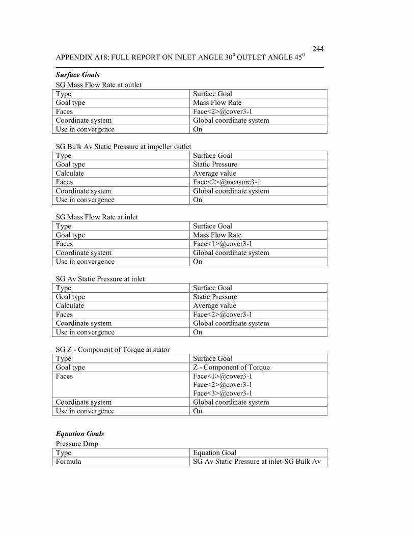
APPENDIX A18: FULL REPORT ON INLET ANGLE 300 OUTLET ANGLE 450244
Surface GoalsSG Mass Flow Rate at outletType Surface GoalGoal type Mass Flow RateFaces Face<2>@cover3-1Coordinate system Global coordinate systemUse in convergence On
SG Bulk Av Static Pressure at impeller outletType Surface GoalGoal type Static PressureCalculate Average valueFaces Face<2>@measure3-1Coordinate system Global coordinate systemUse in convergence On
SG Mass Flow Rate at inletType Surface GoalGoal type Mass Flow RateFaces Face<1>@cover3-1Coordinate system Global coordinate systemUse in convergence On
SG Av Static Pressure at inletType Surface GoalGoal type Static PressureCalculate Average valueFaces Face<2>@cover3-1Coordinate system Global coordinate systemUse in convergence On
SG Z - Component of Torque at statorType Surface GoalGoal type Z - Component of TorqueFaces Face<1>@cover3-1
Face<2>@cover3-1Face<3>@cover3-1
Coordinate system Global coordinate systemUse in convergence On
Equation GoalsPressure DropType Equation GoalFormula SG Av Static Pressure at inlet-SG Bulk Av

APPENDIX A18: FULL REPORT ON INLET ANGLE 300 OUTLET ANGLE 450245
Static Pressure at impeller outletDimensionality Pressure & stressUse in convergence On
Torque on impellerType Equation GoalFormula GG Z - Component of Torque -SG Z -
Component of Torque at statorDimensionality TorqueUse in convergence On
EfficiencyType Equation GoalFormula Pressure Drop*{Inlet Volume Flow
1:Volume flow rate normal to face:1.010e-003}/282.74/Torque on impeller
Dimensionality No unitsUse in convergence On
Component Control InfoDisabled components: Extrude1@measure3-1@Assembly3_inlet30_outlet45
Calculation Control Options
Finish ConditionsFinish conditions If one is satisfiedMaximum travels 4Goals convergence Analysis interval: 0.5
Solver RefinementRefinement: Disabled
Results SavingSave before refinement On
Advanced Control OptionsFlow FreezingFlow freezing strategy Disabled

APPENDIX A18: FULL REPORT ON INLET ANGLE 300 OUTLET ANGLE 450246
RESULTS
General InfoIterations: 196CPU time: 842 s
LogMesh generation started 15:01:13 , Feb 20Mesh generation normally finished 15:01:20 , Feb 20Preparing data for calculation 13:22:30 , Jul 21Calculation started 0 13:22:34 , Jul 21Calculation has converged since thefollowing criteria are satisfied: 195
13:37:00 , Jul 21
Goals are converged 195Calculation finished 196 13:37:04 , Jul 21
Warnings: A vortex crosses the pressure opening Boundary Condition : EnvironmentPressure 1 ; Inlet flow/outlet flow=0.654743
Calculation Mesh
Basic Mesh DimensionsNumber of cells in X 40Number of cells in Y 40Number of cells in Z 6
Number Of CellsTotal cells 49801Fluid cells 22314Solid cells 11419Partial cells 16068Irregular cells 0Trimmed cells 35
Maximum refinement level: 1
GoalsName Unit Value Progress Use in
convergence
Delta Criteria
GG Z -Component of
N*m -0.661783 100 On 0.00307707714
0.0954172366

APPENDIX A18: FULL REPORT ON INLET ANGLE 300 OUTLET ANGLE 450247
TorqueSG MassFlow Rateat outlet
kg/s -1.00784 100 On 0.00044280674
0.00100784075
SG BulkAv StaticPressure atimpelleroutlet
Pa 97864.5 100 On 90.0547681
91.4530727
SG MassFlow Rateat inlet
kg/s 1.00754 100 On 0 0.00100753736
SG AvStaticPressure atinlet
Pa 50005.8 100 On 1010.15622
1215.20297
SG Z -Component ofTorque atstator
N*m -0.0427399
100 On 0.00194122427
0.00196554622
Torque onimpeller
N*m -0.619043 100 On 0.00497709626
0.0934605635
PressureDrop
Pa -47858.8 100 On 1058.99338
1133.16828
Efficiency 0.276169 100 On 0.00578683543
0.00706834657
Min/Max TableName Minimum MaximumPressure [Pa] -37831.8 137165Temperature [K] 293.148 293.223Density [kg/m^3] 997.561 997.575Velocity [m/s] 0 17.7307X-velocity [m/s] -13.7236 13.4026Y-velocity [m/s] -15.1734 9.49496Z-velocity [m/s] -15.3079 10.1141Heat Transfer Coefficient[W/m^2/K]
0 0
Shear Stress [Pa] 2.42096e-007 6521.84Surface Heat Flux [W/m^2] 0 0Water Mass Fraction [ ] 1 1Water Volume Fraction [ ] 1 1Fluid Temperature [K] 293.148 293.223
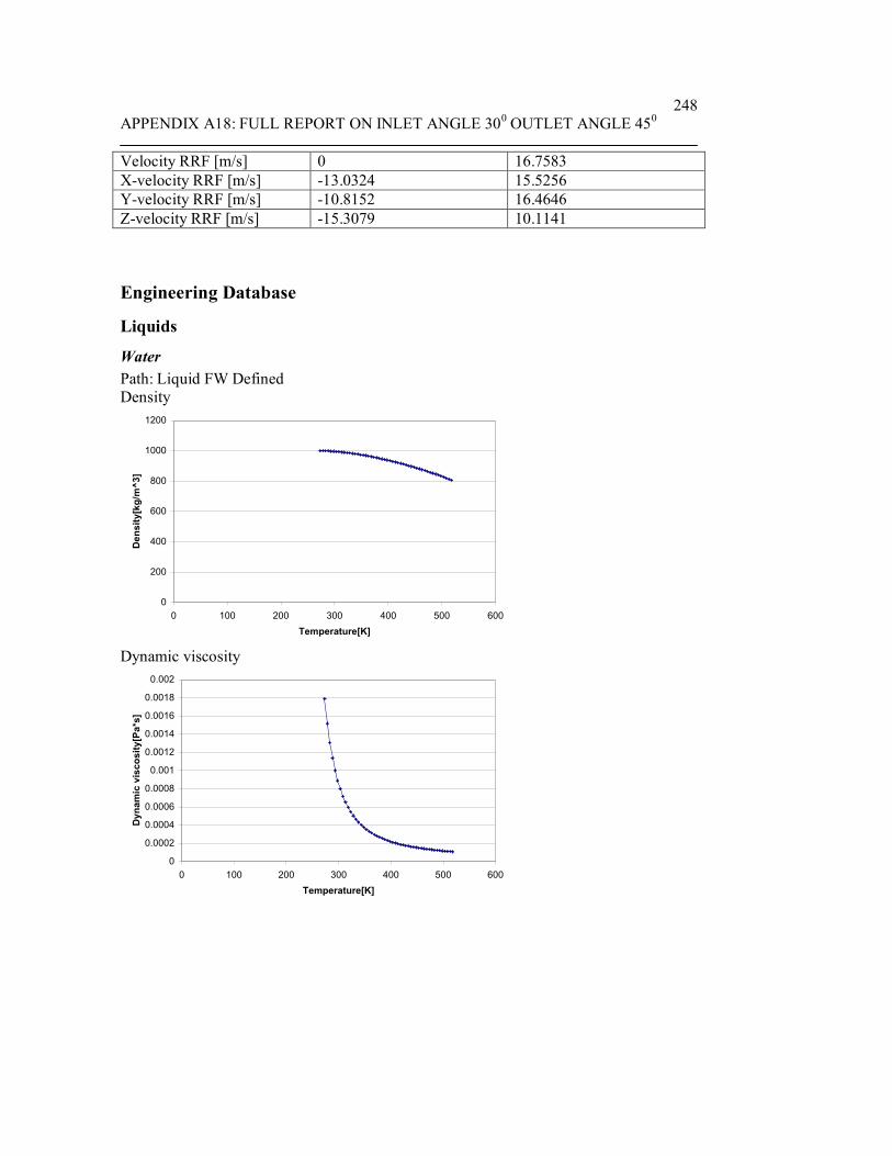
APPENDIX A18: FULL REPORT ON INLET ANGLE 300 OUTLET ANGLE 450248
Velocity RRF [m/s] 0 16.7583X-velocity RRF [m/s] -13.0324 15.5256Y-velocity RRF [m/s] -10.8152 16.4646Z-velocity RRF [m/s] -15.3079 10.1141
Engineering Database
Liquids
WaterPath: Liquid FW DefinedDensity
0
200
400
600
800
1000
1200
0 100 200 300 400 500 600Temperature[K]
Den
sity
[kg/
m^3
]
Dynamic viscosity
0
0.0002
0.0004
0.0006
0.0008
0.001
0.0012
0.0014
0.0016
0.0018
0.002
0 100 200 300 400 500 600Temperature[K]
Dyn
amic
vis
cosi
ty[P
a*s]

APPENDIX A18: FULL REPORT ON INLET ANGLE 300 OUTLET ANGLE 450249
Specific heat (Cp)
4100
4200
4300
4400
4500
4600
4700
4800
4900
0 100 200 300 400 500 600Temperature[K]
Spec
ific
heat
(Cp)
[J/(k
g*K
)]
Thermal conductivity
0
0.1
0.2
0.3
0.4
0.5
0.6
0.7
0.8
0 100 200 300 400 500 600Temperature[K]
Ther
mal
con
duct
ivity
[W/(m
*K)]

APPENDIX A19: FULL REPORT ON INLET ANGLE 300 OUTLET ANGLE 500250
System InfoProduct EFD.Lab 8 1.0. Build: 413Computer name FEA2User name AdministratorProcessors Dual Core AMD Opteron(tm) Processor
280( 4 processors)
Memory 16382 MB / 8388607 MBOperating system Microsoft Windows XP Professional x64
Edition Service Pack 2 (Build 3790)CAD version SolidWorks 2007 SP0CPU speed 2411 MHz
General InfoModel C:\Documents and
Settings\Administrator\Desktop\Fuhnwi\EFD_final\simulate9_inlet30_outlet50\Assem4_inlet30_outlet50.SLDASM
Project name inlet30_outlet50Project path C:\Documents and
Settings\Administrator\Desktop\Fuhnwi\EFD_final\simulate9_inlet30_outlet50\1\1.fwp
Units system SI (m-kg-s)Analysis type InternalExclude cavities without flow conditions OnCoordinate system Global coordinate systemReference axis X
INPUT DATA
Initial Mesh SettingsAutomatic initial mesh: OnResult resolution level: 5Advanced narrow channel refinement: OffRefinement in solid region: Off
Geometry ResolutionEvaluation of minimum gap size: ManualMinimum gap size: 0.04 mEvaluation of minimum wall thickness: ManualMinimum wall thickness: 0.01 m

APPENDIX A19: FULL REPORT ON INLET ANGLE 300 OUTLET ANGLE 500251
Computational Domain
SizeX min -0.0459669402 mX max 0.0502250598 mY min -0.0401346033 mY max 0.0560573967 mZ min -0.00654898132 mZ max 0.0100842688 m
Boundary Conditions2D plane flow NoneAt X min DefaultAt X max DefaultAt Y min DefaultAt Y max DefaultAt Z min DefaultAt Z max Default
Physical FeaturesHeat conduction in solids: OffTime dependent: OffGravitational effects: OffFlow type: Laminar onlyCavitation: OffHigh Mach number flow: OffDefault roughness: 0 micrometer
Rotating Reference FrameAxis of coordinate system ZVelocity 282.74 m/s
Default wall conditions: Adiabatic wall
Initial ConditionsThermodynamic parameters Static Pressure: 101325 Pa
Temperature: 293.2 KVelocity parameters Velocity vector
Velocity in X direction: 0 m/sVelocity in Y direction: 0 m/sVelocity in Z direction: 0 m/sRelative to rotating frame: Off

APPENDIX A19: FULL REPORT ON INLET ANGLE 300 OUTLET ANGLE 500252
Material Settings
FluidsWater
Boundary ConditionsInlet Volume Flow 1Type Inlet Volume FlowFaces Face <1 >Coordinate system Face Coordinate SystemReference axis XFlow parameters Flow vectors direction: Normal to face
Volume flow rate normal to face: 0.00101m^3/sRelative to rotating frame: NoFully developed flow: NoInlet profile: 0
Thermodynamic parameters Temperature: 293.2 K
stator WallType Real wallFaces Face <1 >
Face <1 >Face <1 >
Coordinate system Global coordinate systemReference axis X
Environment Pressure 1Type Environment PressureFaces Face <1 >Coordinate system Global coordinate systemReference axis XThermodynamic parameters Environment pressure: 101325 Pa
Temperature: 293.2 K
Goals
Global GoalsGG Z - Component of TorqueType Global GoalGoal type Z - Component of TorqueCoordinate system Global coordinate systemUse in convergence On

APPENDIX A19: FULL REPORT ON INLET ANGLE 300 OUTLET ANGLE 500253
Surface GoalsSG Bulk Av Static Pressure at impeller outletType Surface GoalGoal type Static PressureCalculate Average valueFaces Face<2>@measure4-1Coordinate system Global coordinate systemUse in convergence On
SG Mass Flow Rate at inletType Surface GoalGoal type Mass Flow RateFaces Face<5>@cover4-1Coordinate system Global coordinate systemUse in convergence On
SG Av Static Pressure at inletType Surface GoalGoal type Static PressureCalculate Average valueFaces Face<2>@cover4-1Coordinate system Global coordinate systemUse in convergence On
SG Mass Flow Rate at outletType Surface GoalGoal type Mass Flow RateFaces Face<2>@cover4-1Coordinate system Global coordinate systemUse in convergence On
SG Z - Component of Torque at statorType Surface GoalGoal type Z - Component of TorqueFaces Face<2>@cover4-1
Face<1>@cover4-1Face<3>@cover4-1
Coordinate system Global coordinate systemUse in convergence On
Equation GoalsPressure DropType Equation GoalFormula SG Av Static Pressure at inlet-SG Bulk Av

APPENDIX A19: FULL REPORT ON INLET ANGLE 300 OUTLET ANGLE 500254
Static Pressure at impeller outletDimensionality Pressure & stressUse in convergence On
Torque on impellerType Equation GoalFormula GG Z - Component of Torque -SG Z -
Component of Torque at statorDimensionality TorqueUse in convergence On
EfficiencyType Equation GoalFormula Pressure Drop*{Inlet Volume Flow
1:Volume flow rate normal to face:1.010e-003}/282.74/Torque on impeller
Dimensionality No unitsUse in convergence On
Component Control InfoDisabled components: Extrude1@measure4-1@Assem4_inlet30_outlet50
Calculation Control Options
Finish ConditionsFinish conditions If one is satisfiedMaximum travels 4Goals convergence Analysis interval: 0.5
Solver RefinementRefinement: Disabled
Results SavingSave before refinement On
Advanced Control OptionsFlow FreezingFlow freezing strategy Disabled

APPENDIX A19: FULL REPORT ON INLET ANGLE 300 OUTLET ANGLE 500255
RESULTS
General InfoIterations: 295CPU time: 3099 s
LogMesh generation started 20:27:14 , Feb 20Mesh generation normally finished 20:27:21 , Feb 20Preparing data for calculation 18:35:33 , Jul 21Calculation started 0 18:35:45 , Jul 21Calculation has converged since thefollowing criteria are satisfied: 294
19:28:06 , Jul 21
Max. travel is reached 294Calculation finished 295 19:28:11 , Jul 21
Warnings: A vortex crosses the pressure opening Boundary Condition : EnvironmentPressure 1 ; Inlet flow/outlet flow=0.638591
Calculation Mesh
Basic Mesh DimensionsNumber of cells in X 40Number of cells in Y 40Number of cells in Z 6
Number Of CellsTotal cells 49780Fluid cells 22160Solid cells 11524Partial cells 16096Irregular cells 0Trimmed cells 37
Maximum refinement level: 1
GoalsName Unit Value Progress Use in
convergence
Delta Criteria
GG Z -Component of
N*m -0.564819 100 On 0.0148669575
0.0851981452

APPENDIX A19: FULL REPORT ON INLET ANGLE 300 OUTLET ANGLE 500256
TorqueSG BulkAv StaticPressure atimpelleroutlet
Pa 98191.1 8.1 On 1136.09135
92.2586084
SG MassFlow Rateat inlet
kg/s 1.00754 100 On 0 0.00100753736
SG AvStaticPressure atinlet
Pa 52491.7 86.8 On 1308.30385
1136.63645
SG MassFlow Rateat outlet
kg/s -1.00885 100 On 0.000134708076
0.00100884674
SG Z -Component ofTorque atstator
N*m -0.0195632
100 On 0.00161460765
0.00163570832
Torque onimpeller
N*m -0.545256 100 On 0.0157663626
0.0836902501
PressureDrop
Pa -45699.5 43.2 On 2441.2305 1055.1798
Efficiency 0.299395 35.8 On 0.0168095305
0.00601802565
Min/Max TableName Minimum MaximumPressure [Pa] -29979 136683Temperature [K] 293.103 293.223Density [kg/m^3] 997.561 997.586Velocity [m/s] 0 14.9925X-velocity [m/s] -13.98 9.60818Y-velocity [m/s] -11.564 12.331Z-velocity [m/s] -8.31073 6.72397Heat Transfer Coefficient[W/m^2/K]
0 0
Shear Stress [Pa] 7.30753e-007 7945.8Surface Heat Flux [W/m^2] 0 0Water Mass Fraction [ ] 1 1Water Volume Fraction [ ] 1 1Fluid Temperature [K] 293.103 293.223

APPENDIX A19: FULL REPORT ON INLET ANGLE 300 OUTLET ANGLE 500257
Velocity RRF [m/s] 0 16.3495X-velocity RRF [m/s] -10.8376 16.2268Y-velocity RRF [m/s] -13.6908 13.0448Z-velocity RRF [m/s] -8.31073 6.72397
Engineering Database
Liquids
WaterPath: Liquid FW DefinedDensity
0
200
400
600
800
1000
1200
0 100 200 300 400 500 600Temperature[K]
Den
sity
[kg/
m^3
]
Dynamic viscosity
0
0.0002
0.0004
0.0006
0.0008
0.001
0.0012
0.0014
0.0016
0.0018
0.002
0 100 200 300 400 500 600Temperature[K]
Dyn
amic
vis
cosi
ty[P
a*s]

APPENDIX A19: FULL REPORT ON INLET ANGLE 300 OUTLET ANGLE 500258
Specific heat (Cp)
4100
4200
4300
4400
4500
4600
4700
4800
4900
0 100 200 300 400 500 600Temperature[K]
Spec
ific
heat
(Cp)
[J/(k
g*K
)]
Thermal conductivity
0
0.1
0.2
0.3
0.4
0.5
0.6
0.7
0.8
0 100 200 300 400 500 600Temperature[K]
Ther
mal
con
duct
ivity
[W/(m
*K)]