computational aerodynamics and flight stability of wing-in ... · isolation is longitudinally...
TRANSCRIPT
Procedia Engineering 67 ( 2013 ) 15 – 24
Available online at www.sciencedirect.com
1877-7058 © 2013 The Authors. Published by Elsevier Ltd. Selection and peer-review under responsibility of the National Chiao Tung Universitydoi: 10.1016/j.proeng.2013.12.002
ScienceDirect
7th Asian-Pacific Conference on Aerospace Technology and Science, 7th APCATS 2013 Computational Aerodynamics and Flight Stability of Wing-In-
Ground (WIG) Craft H. Wanga, C. J. Teoa,*, B. C. Khooa, C. J. Goha,b
aDepartment of Mechanical Engineering, National University of Singapore, 9 Engineering Drive 1, Singapore 117576, Singapore
bDepartment of Mathematics and Statistics, University of Western Australia, 35 Say Crawley, Perth Wesern Australia 6009, Australia
Abstract
A Wing-In-Ground (WIG) craft is a marine craft equipped with wings which enables it to remain airborne just above the water surface. A WIG-craft utilizes ground proximity effects to improve aerodynamic loading and efficiency. It fills the technological gap between conventional aircraft and ships. A WIG-craft operates at much higher speeds than ships and more efficiently than aircraft. Another distinct advantage of a WIG-craft is its ability to take off anywhere from the sea surface without the need for a runway. Due to its superb and unique features, WIG-crafts serve as a promising choice of fast, safe and efficient platform for the next generation of marine transportation systems. The objective of this work is to investigate the aerodynamic characteristics, as well as the longitudinal flight dynamics and stability of WIG-craft for the purpose of achieving improved WIG-craft designs.
© 2013 The Authors. Published by Elsevier Ltd. Selection and peer-review under responsibility of the National Chiao Tung University.
Keywords: Wing-in-Ground (WIG) craft, ground effect, aerodynamics, flight dynamics, stability
Nomenclature
ACH aerodynamic center of height ACP aerodynamic center of pitch b half span C chord length of wing root CL lift coefficient CD_i induced drag coefficient
* Corresponding author. Tel.: +65-6516-8037; fax: +65-6516-8037. E-mail address: [email protected]
© 2013 The Authors. Published by Elsevier Ltd. Open access under CC BY-NC-ND license.Selection and peer-review under responsibility of the National Chiao Tung University
Open access under CC BY-NC-ND license.

16 H. Wang et al. / Procedia Engineering 67 ( 2013 ) 15 – 24
h height of wing trailing edge to ground
1. Introduction
Wing-In-Ground (WIG) effect transportation vehicles have attracted considerable attention in view of their potential civil and military applications. Some of the benefits of WIG-craft include high speed operation (compared to traditional marine craft), improved payload and aerodynamic efficiency. One of the earliest WIG-craft which contributed significantly to WIG-craft technology was the Russian Ekranoplan. A series of Ekranoplan, namely the SM and KM series, has been successfully constructed by Russian engineers. They all share some common characteristics, such as an aircraft-like configuration (wing, fuselage and tail), a rectangular wing with low aspect ratio, together with a large and high tail for longitudinal flight stability. One obvious feature of the Ekranoplan is the use of Power Augmented Ram (PAR) to assist takeoff by directing the exhaust air from the engine over the main wing. Another type of WIG-craft, which is characterized by a Reversed Delta wing and a high tail configuration, has been designed by Lippisch, a German aerodynamicist. The Lippisch type of WIG-craft is the only one that has proven to be inherently stable in ground effect (GE) [1]. WIG-craft research and development have also been undertaken in other countries such as Japan, China, US and Korea.
The aerodynamic characteristics of 2D airfoils and 3D wings in GE have been investigated both experimentally and numerically by other researchers [2-4]. The general conclusion is that there is a reduction in induced drag and an increase in lift as the ground is approached. As a result, both aerodynamic efficiency and aerodynamic loading are increased due to ground proximity effects. Pioneer researchers such as Kumar [5], Irodov [6], and Staufenbiel [7] have analyzed various aspects of WIG-craft longitudinal stability. In particular, Irodov [6] analyzed the longitudinal stability of a WIG-craft subjected to the assumption of constant operating speed. One of his main conclusions is that in order for a WIG-craft to be longitudinally stable, its aerodynamic center of height (ACH) must lie ahead of its aerodynamic center of pitch (ACP). This simple criterion may serve as a first-order rule of thumb in preliminary WIG-craft design. Even though extensive work has been performed independently on the aerodynamics and flight stability of WIG-craft, the coupling between WIG-craft aerodynamics and flight stability has not been adequately addressed. WIG-craft design is unique in the sense that both aerodynamic performance and flight stability have to be simultaneously considered during the preliminary stage of the conceptual design. In this paper, we analyze both the aerodynamics and stability of a 2D airfoil and a Lippisch type of WIG-craft. Results for a 2D airfoil operating in GE are presented to elucidate the general variation of lift coefficient CL, ACH and ACP. The effects of salient design parameters of a WIG-craft, such as wing anehdral, winglet, tail height, tail distance from main wing, S- shaped wing section, and viscous effects on both the aerodynamics and flight stability of a WIG-craft model have been investigated. Eigenvalue analysis is performed to investigate the effects of various aerodynamic derivatives on the longitudinal stability of a WIG-craft. Optimization studies have also been performed on the main wing to improve the aerodynamic efficiency. Systematic investigation of WIG-craft aerodynamics and flight stability constitutes an important facet of sophisticated WIG-craft design and optimization.

17 H. Wang et al. / Procedia Engineering 67 ( 2013 ) 15 – 24
2. Computational Aerodynamics of WIG-Craft Model
2.1. Inviscid Computational Aerodynamic Model
Figure 1 Inviscid Wing and Tail model
Inviscid aerodynamic computations have been performed on a wing-tail configuration using a 3D panel
method code. First, the surfaces of the wing-tail configuration are discretized into a number of panels. Typically, 6000 panels are adequate to yield sufficiently accurate results which are independent of the number of panels. Subsequently, the strengths of elementary flow singularities, namely doublet and source distributed on each panel, are solved to satisfy the Kutta-condition at the trailing edge and the flow tangency condition on each panel. As illustrated in Figure 1, ground effects are modeled using the method of images, which ensures no flow penetration through the rigid flat ground. Although the panel method is inviscid in nature, it serves as a robust and computationally efficient workhorse for the parametric study of a wide range of WIG-craft configurations.
2.2. Viscous Computational Aerodynamic Model
Figure 2 Computational domain of WIG-craft model in viscous analysis
To investigate the effects of viscosity on the aerodynamics and longitudinal stability of a WIG-craft, a Finite
Volume method which solves the Navier-Stokes equation incorporating the standard turbulence model is employed. A total of 3 million Finite Volume elements have to be utilized in order to obtain mesh-independent results. The computational time required is significantly longer than that for the panel method. Figure 2 illustrates the computational domain, where C is the root chord of WIG-craft model and b is half span. Both computational domain size and mesh density have been systematically checked to ensure that mesh-independent results are obtained.
4C 8C
4b 4b
18 H. Wang et al. / Procedia Engineering 67 ( 2013 ) 15 – 24
3. Results and Discussion
3.1. Data Validation
(a)
(b)
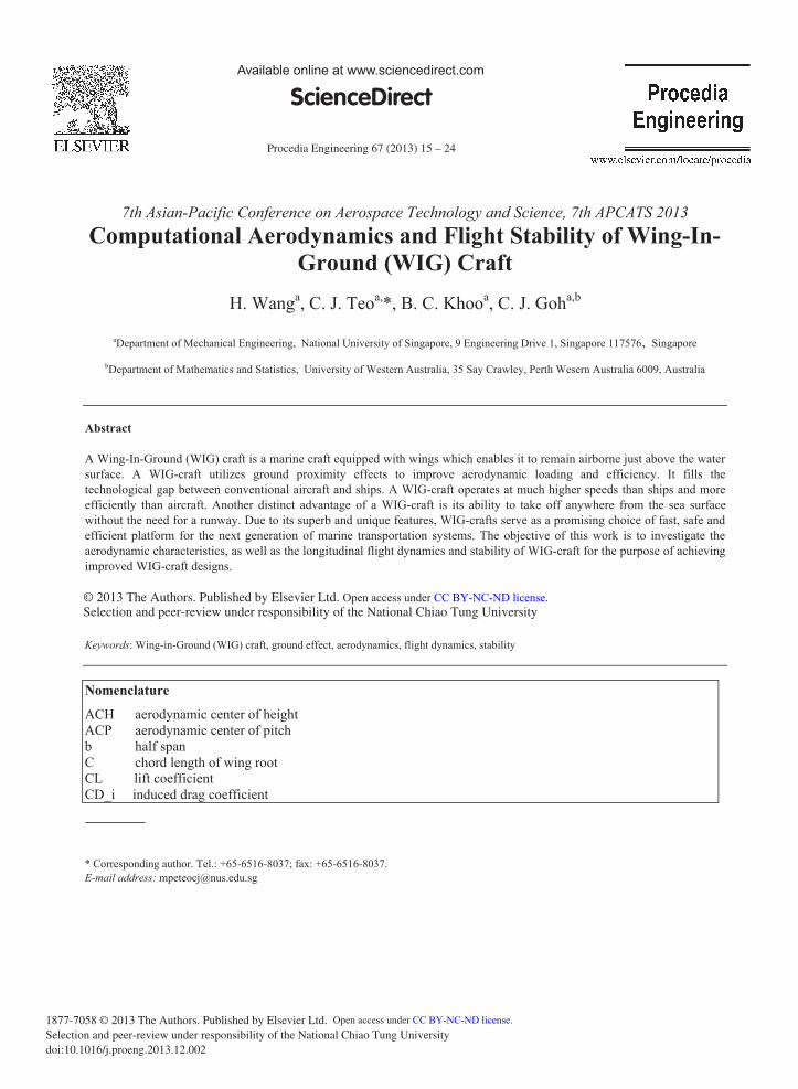
Figure 3 (a) CD_i VS CL comparison (b) CL VS h/C at AoA=4deg comparison As shown in Figure 3(a), the induced drag coefficient (CD_i) versus lift coefficient (CL) curve for a 3D wing
with an aspect ratio (AR) of 20 obtained using a panel method compares well with theoretical results. The induced drag is more sensitive to the leading edge panel density. A denser panel distribution around the leading edge region in the chord-wise direction results in more accurate induced drag results. Figure 3(b) shows the variation of lift coefficient CL versus normalized height h/C from the ground for a 3D rectangular wing with an AR of 100, which may be considered as a 2D airfoil operating in GE. The results compare well with available data in the literature [4]. With proper panel density and distribution, the panel method models the inviscid aerodynamics of a WIG-craft model fairly well.
0
0.01
0.02
0.03
0.04
1 0.5 0 0.5 1 1.5 2
CD_i
CL
CD_i_theoryCD_i_PSWCD_i_theoryCD_i_panel
00.20.40.60.81
1.21.4
0 0.1 0.2 0.3 0.4 0.5 0.6 0.7 0.8 0.9 1
CL
h/C
Literature PSWliterature Panel

19 H. Wang et al. / Procedia Engineering 67 ( 2013 ) 15 – 24
3.2. 2D airfoil Data in GE
(a) (b)
(c)
Figure 4 (a) CL vs h/C under different AoA. (b) ACH vs AoA. (c) ACP vs h/C
Figure 4(a) shows that the lift coefficient CL of a NACA4412 airfoil increases as it approaches the ground. This is due to the higher pressure between airfoil bottom surface and the ground. CL decreases at low angles of attack (AOA) as h/C decreases below 0.1. This is due to the existence of a converging-diverging flow passage between the airfoil’s bottom surface and the ground plane, which culminates in a suction effect. A WIG-craft makes effective use of the increase in CL as the ground is approached to increase both the aerodynamic loading and efficiency. ACH and ACP, which are measured from the leading edge of the NACA4412 airfoil, are shown in Figures 4(b) and 4(c). The negative ACH and ACP values denote that they are located downstream from the airfoil leading edge. It is observed that ACH is located downstream of ACP. Hence, a NACA4412 airfoil in isolation is longitudinally unstable according to the Irodov stability criterion. When viscous effects are taken into account, ACH is shifted upstream whereas the variation in ACP is insignificant. As a consequence, viscous effects which are present in a real flow are beneficial for improving longitudinal flight stability. This observation involving the beneficial effects of viscosity on longitudinal stability has also been verified to be applicable for a 3D WIG-craft model.
0.00.20.40.60.81.01.21.41.6
0 0.2 0.4 0.6
CL
h/C
AoA=5degAoA=3degAoA=1deg
0.6
0.4
0.2
0.02 3 4 5
ACH
ACH_vis_Fluent
ACH from Javafoil
Viscous
Inviscid
AoA(deg)
-0.6
-0.4
-0.2
0.00.1 0.2 0.3 0.4 0.5
ACP
h/C
ACP from Fluent viscous
ACP from JavafoilViscousInviscid

20 H. Wang et al. / Procedia Engineering 67 ( 2013 ) 15 – 24
3.3. Effects of Design Parameters of WIG-craft on Aerodynamics and Stability
Some of the main design parameters, such as anhedral of main wing, winglet, S-shaped section on main wing and tail position, have been thoroughly investigated to reveal their effects on the aerodynamics and stability of a WIG-craft. BL corresponds to a baseline wing-tail configuration, where the wing has an anhedral geometry. The configuration for BL_NO_AN is similar to that for BL, except that the wing has no anhedral. BL_NO_WL corresponds to a configuration which is similar to BL, except that the main wing does not possess a winglet. BL_S corresponds to a wing-tail configuration where the main wing consists of S-shaped airfoil sections. The configuration adopted for BL_H_T is similar to that for BL, with the exception that the tail has been located at an elevated position.
3.3.1. Effects of Anhedral BL BL_NO_AN
Front view Top View
Front view Top View
Figure 5 Comparsion between BL and BL_NO_AN configuration
Wing anhedral increases the aerodynamic efficiency, since the wing tip is located closer to the ground. Wing anhedral causes ACH to be shifted upstream and ACP to be shifted downstream, which is beneficial for longitudinal stability according to the Irodov stability criterion. Wing anhedral is thus beneficial for both aerodynamic efficiency and stability.
3.3.2. Effects of winglet
BL BL_NO_WL
Front view Top View
Front view Top View
Figure 6 Comparsion between BL and BL_NO_WL configuration
21 H. Wang et al. / Procedia Engineering 67 ( 2013 ) 15 – 24
A winglet significantly enhances the aerodynamic efficiency of a WIG-craft. The winglet has negligible effects on the ACH position, but causes a forward shift in the ACP position, which is undesirable for longitudinal stability. The presence of a winglet thus improves aerodynamic efficiency at the expense of longitudinal stability.
3.3.3. Effects of tail position
BL BL_H_T
Front view Side View Front view Side View
Figure 7 Comparsion between BL and BL_H_T configuration
The configuration with a higher tail has insignificant effects on the aerodynamic efficiency. However, a higher tail causes ACH to shift forwards and ACP to shift backwards. Hence, a higher tail is desirable for longitudinal stability. Similar results have been obtained for a tail which has been shifted backwards. However, structural considerations will also have to be accounted for in ascertaining the most appropriate location of the tail.
3.4. Parametric Study of Aerodynamic Derivatives on WIG-Craft Stability
(a)

22 H. Wang et al. / Procedia Engineering 67 ( 2013 ) 15 – 24
(b)
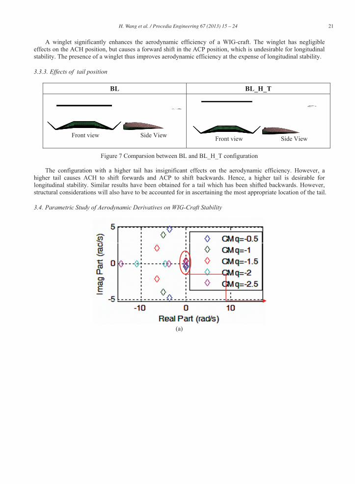
Figure 8 (a) Root locus of WIG-craft model under varying CMq (b) Long period mode
Classical fourth-order linearized longitudinal flight stability analysis [8] has been modified to incorporate ground effects. The introduction of an additional state variable h corresponding to the height of the WIG craft above the ground causes the original 4 by 4 stability matrix to become a 5 by 5 matrix. Effects of various aerodynamic derivatives on the eigenvalues have been investigated. Figure 8(a) shows a typical root locus plot of a WIG-craft model subjected to varying magnitudes of moment coefficient with respect to pitch rate (CMq). As the magnitude of CMq increases, the eigenvalues corresponding to the short period mode move towards the real-axis before bifurcating into two real roots. The eigenvalues corresponding to the long period are shown in Figure 8(b) and they shift more towards the negative real-axis, thus signifying a larger damping ratio and a more stable long period mode as the magnitude of CMq increases. CMq does not have significant effects on the non-oscillating root lying close to the long period mode.
Eigenvalue analysis reveals that the longitudinal stability of a WIG-craft is more sensitive to parameters such as ACH, ACP and CG location. The eigenvalue analysis may be employed for determining the optimal distance between ACH and ACP for achieving maximum damping ratio corresponding to the long period mode. The optimal CG location for achieving maximum damping ratio of long period mode may also be determined.
3.5. WIG Craft Optimization
(a)

23 H. Wang et al. / Procedia Engineering 67 ( 2013 ) 15 – 24
(b) Figure 9 (a) Geometry comparison between baseline (BL) wing and optimized wing (b) CL/CD_i vs number of
iteration
A gradient based local optimization method has been implemented to optimize the geometry of the main wing for improving the aerodynamic efficiency. The wing projected area has been kept constant during the optimization process. A comparison of the baseline wing (shaded part) and the optimized wing after 19 iteration steps is shown in Figure 9(a). It can be seen that the optimized wing has an elongated span and a reduced root chord. The aerodynamic efficiency of the optimized wing has been improved significantly by 44% compared to the baseline wing configuration. The optimization procedure has proven to be efficient and robust. Different boundary constraints of design parameters may be implemented easily. Further optimization studies will be carried out in the near future. However, it should be noted that while aerodynamic efficiency has improved, the corresponding longitudinal stability cannot be immediately assured.
3.6. Viscous Effects on WIG-Craft Aerodynamic Performance and Stability
(a)
(b) Figure 10 (a) viscous wing tip streamline visualization (b) inviscid wing tip streamline visualization
202224262830323436
0 2 4 6 8 10 12 14 16 18 20NO of Iterations
0
19
CL/CD_i
BL_RD
Optimized RD

24 H. Wang et al. / Procedia Engineering 67 ( 2013 ) 15 – 24
Figure 10 shows a plot of the cross-stream velocity vectors corresponding to a WIG-craft model at h/C=0.2. For low h/C, the vortices near the wing-tips become more concentrated and the induced velocity near the mid-span of the wing is reduced, thus leading to a reduction in induced drag. As a consequence, the aerodynamic efficiency is further improved due to a reduction in induced drag. Similar to previous observations pertaining to viscous effects on the aerodynamics and stability of a 2D airfoil, ACH of a 3D WIG- model shifts forwards, whereas ACP remains unchanged, which improves stability in accordance to Irodov’s stability criterion. In terms of aerodynamic efficiency, viscous aerodynamic analysis yields more realistic predictions for the aerodynamic efficiency, since skin friction drag is accounted for. In WIG-craft design, viscous effects should be minimized to maximize aerodynamic efficiency, even though viscous effects are beneficial for stability. Stability should be enhanced through other design features, such as wing anhedral, tail geometry and location.
4. Conclusion
Both the aerodynamics and longitudinal stability of a WIG-craft model have been investigated numerically. The Panel method has been demonstrated to be robust and computationally efficient in analyzing the inviscid aerodynamics of a WIG-craft. Viscous effects have been found to enhance longitudinal stability (assessed using Irodov’s criterion) by bringing about a forward shift in ACH. Results on the effects of WIG-craft design parameters, such as wing anhedral, winglet, and tail position, are important for the conceptual design of a WIG-craft. As discussed in Section 3, some design parameters, such as winglet, have contradicting effects on aerodynamic efficiency and stability. A compromise thus has to be made in terms of aerodynamic efficiency and stability in selecting the appropriate combination of design parameters. Investigation on the effects of various aerodynamic derivatives is imperative for the conceptual design. For example, a large CMq is desirable for achieving a large damping ratio. In order to achieve a large CMq, a large tail, or a tail located further backwards, is required. Optimization studies performed to improve the aerodynamic efficiency have led to an improvement of 40% with respect to a baseline wing configuration. The systematic and extensive investigation on both the aerodynamics and longitudinal stability of WIG-craft provides the basis for the design of more efficient and stable WIG-craft.
Acknowledgements
This research was supported by the Singapore Ministry of Education Academic Research Fund (Tier 1), Maritime Port Authority (MPA) of Singapore, and Wigetworks Pte. Ltd.
References
[1]. Flugmechanik, F. Background of FF. 2013; Available from:http://www.fischerflugmechanik.com/site/index.php? menu=background. [2]. Barber, T., Aerodynamic ground effect: A case study of the integration of CFD and experiments. International Journal of Vehicle Design,
2006. 40(Compendex): p. 299-316. [3]. Carter, A.W., Effects of ground proximity on the longitudinal aerodynamic characteristics of an unswept aspect-ratio-10 wing. 1970. [4]. Smith, J.L., H.Z. Graham, and J.E. Smith. The Validation of an airfoil in the ground effect regime using 2-D CFD analysis. in 26th AIAA
Aerodynamic Measurement Technology and Ground Testing Conference, June 23, 2008 - June 26, 2008. 2008. Seattle, WA, United states: American Institute of Aeronautics and Astronautics Inc.
[5]. Kumar, P., Some stability problems of ground effect wing vehicles in forward motion. Aeronautical Quarterly, 1972. 23(1): p. 41-52. [6]. Irodov, R.D., Criteria of the Longitudinal Stability of the Ekranoplan, in Criteria of the Longitudinal Stability of the Ekranoplan--
Translation.1974: United States. p. 20p. [7]. Staufenbiel, R.W. and U.J. Schlichting, Stability of Airplanes in Ground Effect. J. Aircraft, Vol. 25, no. 4, , 1988. [8]. Nelson, R.C., Flight stability and automatic control1998: WCB/McGraw Hill.