computation of viscous flow inside a double-channel ... software,unigraphics nx,is used ... the...
TRANSCRIPT

Send Orders for Reprints to [email protected]
The Open Mechanical Engineering Journal, 2014, 8, 613-618 613
1874-155X/14 2014 Bentham Open
Open Access
Computation of Viscous Flow Inside a Double-Channel Centrifugal Pump
Su-Lu Zheng1, Xiang-Ping Wang1, Rui-Hang Zheng*,1, Ai-Ping Xia1, Yi-Nian Wang1 and Yu-Liang Zhang2
1Quzhou Center of Quality Supervision and Technology Testing, Quzhou, 324002, China 2College of Mechanical Engineering, Quzhou University, Quzhou, 324000, China
Abstract: The double-channel centrifugal pumps are widely used to transport the two-phase flow including big solid particles in industry and agriculture. However, the related design theory and the design method are immature by far. In practice, the revised design method based on the pure water medium is still the main method for the solid-liquid two-phase double-channel pump. Therefore, it is very necessary to deeply study the flow characteristics on the condition of the pure water medium. In this paper, in order to study the flow characteristics inside a prototype double-channel centrifugal pump in the case that the delivered medium is the pure water, the SIMPLE algorithm, RNG κ-ε turbulence model, and frozen rotor method are employed to calculate the incompressible, viscous, three-dimensional internal flow. The calculation results display the variation characteristics of the internal flow field and the external performance. The results show that the predicted pump head drops with the increasing flow rate, which manifest that the pump model is of good operation stability at the whole range of working. At the design point, a strong and large vortex remain appears at the middle section of the double-channel impeller. The computational fluids dynamic technology is competent to assess the internal viscous flow inside a double-channel centrifugal pump.
Keywords: Centrifugal pump, double-channel, hydraulic performance, numerical simulation.
1. INTRODUCTION
Centrifugal pumps are widely used to deliver all kinds of medium, which include liquid phase, solid phase, and gas phase, etc. In this community, the usage of the solid-liquid two-phase flow pumps is very wide. For the solid-liquid two-phase flow especially for including big solid particles, the application of the double-channel centrifugal pump is wider. The double-channel centrifugal pump is widely used to transport slurry, paper pulp, sewage and other substances, etc. due to the symmetrical flow passages, good balance and smooth operation. In recently years, with the rapid development of the computer capacity and the computational fluid dynamics (CFD), the numerical simulation method has become an important tool to study flow problems in pumps and predict pump performance [1-6] For example, Inoue [7], Medvitz [8] and Franklyn et al. [9], used the CFD technology to investigate the internal flow characteristics of the external hydraulic performance for different research objectives. The objective of this paper is to predict the external hydraulic performance and to reveal the internal flow field of a prototype double-channel centrifugal pump by using computational fluid dynamic method. In the process of predicting external performance, the volumetric loss and the disc loss are taken into account in this paper.
2. PHYSICAL MODEL AND METHOD
2.1. Pump Model
In this paper, the studied pump model is a prototype double-channel centrifugal pump. In other words, it has two blades. The main design parameters are following. Flow rate, 150 m3/h; Head, 65 m; Rotational speed, 2900 r/min. Other main geometric parameters are following. Impeller diameter, 260 mm; Suction diameter, 125 mm; Discharge diameter, 100 mm; Throat diameter, 65 mm.
2.2. Control Equation
2.2.1. Mass Conservation Equation
∂ρ∂t
+ ρ∇ ⋅V = 0 (1)
The mass conservation equation is suitable to the compressible and the incompressible flow.
2.2.2. Momentum Conservation Equation
The component equations at x, y and z directions are following;
∂(ρu)∂t
+ div(ρuu) = − ∂p∂x
+ div(µgradu) + Su
∂(ρv)∂t
+ div(ρvu) = − ∂p∂y
+ div(µgradv) + Sv
∂(ρw)∂t
+ div(ρwu) = − ∂p∂z
+ div(µgradw) + Sw
⎧
⎨
⎪⎪⎪
⎩
⎪⎪⎪
(2)
614 The Open Mechanical Engineering Journal, 2014, Volume 8 Zheng et al.
where Su, Sv, Sw are the source items of the momentum conservation equation. Su=Fx+Sx, Sv=Fy+Sy, Sw=Fz+Sz.. Fx, Fy and Fz stand for the body force acting on the fluid element. In which Sx, Sy, Sz. are described as following:
Sx =∂∂x
µ ∂u∂x
⎛⎝⎜
⎞⎠⎟+ ∂∂y
µ ∂v∂x
⎛⎝⎜
⎞⎠⎟+ ∂∂z
µ ∂w∂x
⎛⎝⎜
⎞⎠⎟+ ∂∂x
λdivu( )
Sy =∂∂x
µ ∂u∂y
⎛⎝⎜
⎞⎠⎟+ ∂∂y
µ ∂v∂y
⎛⎝⎜
⎞⎠⎟+ ∂∂z
µ ∂w∂y
⎛⎝⎜
⎞⎠⎟+ ∂∂y
λdivu( )
Sz =∂∂x
µ ∂u∂z
⎛⎝⎜
⎞⎠⎟+ ∂∂y
µ ∂v∂z
⎛⎝⎜
⎞⎠⎟+ ∂∂z
µ ∂w∂z
⎛⎝⎜
⎞⎠⎟+ ∂∂z
λdivu( )
⎧
⎨
⎪⎪⎪⎪
⎩
⎪⎪⎪⎪
(3)
2.2.3. Reynolds Average Equation
The three-dimensional, viscous, and unsteady turbulence flow inside centrifugal pump can be described through Reynolds average equation;
∂ui
∂xi
= 0
ρ∂ui
∂t+ ρuj
∂ui
∂x j
= ρFi −∂p∂xi
+ µ∂2ui
∂x j∂x j
− ρ ∂∂x j
ui'uj
'( )
⎧
⎨
⎪⎪
⎩
⎪⎪
(4)
where ρ is the fluid density, −ρui
'uj' stands for the average
Reynolds stress. According to Boussinesq assumption, the average Reynolds stress can be written as:
−ρui
'uj' = µt
∂ui
∂x j
+∂uj
∂xi
⎛
⎝⎜
⎞
⎠⎟ −
23
ρk + µt
∂ui
∂xi
⎛
⎝⎜⎞
⎠⎟δ ij (5)
2.2.4. Turbulence Model
The RNG k-ε turbulence model including the influence of high strain rate and large curvature overflowing has been widely verified that it is suitable to simulate the flow inside pump. Consequently, it is employed to close the Reynolds average Navier-Stokes equations;
ρ dk
dt= ∂∂x j
α kµeff
∂k∂x j
⎛
⎝⎜
⎞
⎠⎟ + 2µt Sij
∂ui
∂x j
− ρε (6)
ρ dε
dt= ∂∂x j
αεµeff
∂ε∂x j
⎛
⎝⎜
⎞
⎠⎟ + 2C1ε
εkν t Sij
∂ui
∂x j
− C2ε ρε 2
k− R (7)
where:
Sij =12
∂ui
∂x j
+∂uj
∂xi
⎛
⎝⎜
⎞
⎠⎟
µeff = µ + µt
µt = Cµ
k 2
ε
⎧
⎨
⎪⎪⎪
⎩
⎪⎪⎪
(8)
Here, the parameter R can be described as following:
R =
Cµη3(1−η / η0 )
1+ βη3
ε 2
k,η = Sk / ε (9)
where Cµ=0.0845, C1ε=1.42, C2ε=1.68, αk=1.0, αε=0.769, β=0.012, η0=4.38.
2.3. Calculation Grids
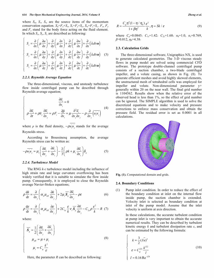
The three-dimensional software, Unigraphics NX, is used to generate calculated geometries. The 3-D viscous steady flows in pump model are solved using commercial CFD software. The prototype double-channel centrifugal pump consists of a suction chamber, a two-blade centrifugal impeller, and a volute casing, as shown in Fig. (1). To generate efficient meshes and avoid highly skewed elements, the unstructured mesh of tetrahedral cells was employed for impeller and volute. Non-dimensional parameter y+ generally within 20 on the near wall. The final grid number is 1104562. Results show when the relative error of the observed head is less than 1%, so the effect of grid number can be ignored. The SIMPLE algorithm is used to solve the discretized equations and to make velocity and pressure corrections to enforce mass conservation and obtain the pressure field. The residual error is set as 0.0001 in all calculations.
Fig. (1). Computational domain and grids.
2.4. Boundary Conditions
(1) Pump inlet condition. In order to reduce the effect of the boundary condition at inlet on the internal flow inside pump, the suction chamber is extended. Velocity inlet is selected as boundary condition at inlet of the pump model. Assume that the inlet velocity is uniform at axis direction.
In these calculations, the accurate turbulent condition at pump inlet is very important to obtain the accurate numerical results. They can be described by turbulent kinetic energy k and turbulent dissipation rate ε, and can be estimated by the following formula:
k = 32
(Iu)2
ε = Cµ3 4 k 3 2
lI ≈ 0.16 Re−1 8
⎧
⎨
⎪⎪⎪
⎩
⎪⎪⎪
(10)

Computation of Viscous Flow Inside a Double-Channel Centrifugal Pump The Open Mechanical Engineering Journal, 2014, Volume 8 615
where l is the turbulent length scale, Cµ = 0.09. (2) Pump outlet condition. Outflow condition is specified
as the outlet boundary condition, and flow rate weighting is set to be 1.0.
(3) Wall condition: As to wall boundary condition, no slip condition is enforced on wall surface and standard wall function is also applied to adjacent region of the walls.
3. RESULTS ANALYSIS
3.1. External Performance
After numerical simulation, the external performance can be obtained by the following expressions.
3.1.1. Pump Head
.
H = Pρg
⎛⎝⎜
⎞⎠⎟ i
N + V 2
2g⎛
⎝⎜⎞
⎠⎟ i
Ni=1
N
∑i=1
N
∑⎧⎨⎪
⎩⎪
⎫⎬⎪
⎭⎪outlet
− Pρg
⎛⎝⎜
⎞⎠⎟ i
M + V 2
2g⎛
⎝⎜⎞
⎠⎟ i
Mi=1
M
∑i=1
M
∑⎧⎨⎪
⎩⎪
⎫⎬⎪
⎭⎪inlet
+ Δh
. (11)
where P and V is the pressure and the absolute velocity at the center of grid cell. M and N are the numbers of grids at the inlet and the outlet of the pump. Δh is the vertical distance between inlet and outlet.
3.1.2. Pump Efficiency
The hydraulic efficiency ηh is calculated as;
ηh =
ρgQHMω
(12)
where Q is known flow rate. M is impeller torque obtained by simulation. ω is the angular velocity.
The variation of the volumetric efficiency ηv is very small in wide range of flow rate, and hence it is usually regarded as an invariable:
ηv = 1
1+ 0.68 ⋅ ns
−23
(13)
Here, the specific speed ns is:
ns =
3.65n QH 0.75 (14)
The total efficiency (η ) of the centrifugal pump can be written as;
η = 1
ηvηh
+ΔPd
Pe
+ 0.03⎛
⎝⎜⎞
⎠⎟
−1
(15)
where Pe is the effective output power, Pe = ρgQH . The disk
friction loss power ΔPd can be described as;
ΔPd =1.1× 75×10−6ρgu2
3D22
0.133×10⁻³ρRe0.134ω 3(D2 / 2)3 D22
⎧⎨⎪
⎩⎪
ns > 65
ns < 65 (16)
where D2 is the diameter of impeller, Re = 106 ×ω (D2 2)2 . In this paper, the predicted pump head and the pump efficiency are shown in Fig. (2). It is seen from Fig. (2) that the predicted pump head displays the decline tendency with the increasing flow rate. In present calculation, when flow rat is 30 m3/h, the predicted pump head is 85 m. At the design point, that is to say, Q=150 m3/h, the predicted pump head H=67 m. When the maximum of flow rate is 210 m3/h, the predicted pump head H=64.14 m. As such, it is concluded that the prototype double-channel centrifugal pump model has very good operation stability at the whole range of working operation. Likewise, the calculation results show that the pump efficiency curve firstly increases and then drops with the increasing flow rate at the whole range of working operation. In present calculation, when flow rat Q=30 m3/h, the predicted pump efficiency η=12%. At the design point, Q=150 m3/h, the predicted pump efficiency is the highest, η=59%. When the maximum of flow rate is 210 m3/h, the predicted pump efficiency η=52%.
(a) Pump head curve
(b) Pump efficiency curve
Fig. (2). Predicted head and efficiency curves through numerical simulation.

616 The Open Mechanical Engineering Journal, 2014, Volume 8 Zheng et al.
3.2. Flow Field
Fig. (3) shows the distribution of static pressure at the middle section of impeller. From Fig. (3), it can be seen that the static pressure gradually increases from center region to outside along the radius direction. For example, at the center of impeller, the relative pressure value is about 0 kPa, while the maximum of the pressure value at the impeller outlet is about 600 kPa. Moreover, it is also seen from this figure that at the same radius of impeller, the static pressure value on working surface is obviously higher than that on the back surface. Meanwhile, the static pressure is the lowest just after the leading edge of the blade at the suction side. In present results, the central lowest absolute pressure are about 101 kPa, and much higher than the vapor pressure of liquid media, 2.3 kPa, so as not to cause cavitation phenomenon.
Fig. (3). Static pressure distribution at middle section(kPa).
It is seen from Fig. (4) that at the design working point, a large and strong vortex appears near the center of impeller. In theory, the flow inside pump is ideal at the design point. In other words, the vortex does not usually display the middle section of impeller. In present model, the blade number is 2. As, such, the blade number is little, therefore the control capacity to flow becomes weaken.
Fig. (4). Relative streamline at middle section.
Fig. (5) shows the distributions of turbulent kinetic energy and turbulence intensity at middle section of impeller. It is clearly seen from Fig. (5a) that the
distributions of turbulent kinetic energy are nonuniform. The turbulent kinetic energy is the highest just after the leading edge of the blade at the suction side. In present results, the highest absolute value is about 3 m2/s2. At the outlet of the impeller, the magnitude of the turbulent kinetic energy is relatively low. The lowest value is about 0.4 m2/s2. Meanwhile, the distribution of the turbulent intensity in Fig. (5b) is also nonuniform. The nonuniform distribution can be attributed to the volute effect. The volute tongue structure causes the internal flow field to display unsymmetrical. As such, the distribution of the internal flow field shows the corresponding result.
(a) Turbulent kinetic energy (m2/s2)
(b) Turbulence intensity
Fig. (5). Distributions of turbulent kinetic energy and turbulence intensity at middle section.
Fig. (6) shows the distributions of the static pressure and the dynamic pressure at meridian plane of impeller. It is found from Fig. (6a) that with the increase of impeller radius, the static pressure value shows the rising tendency. At the center of impeller, the average relative value is about 0 Pa; while in volute, the maximum of the static pressure is about 600 kPa.

Computation of Viscous Flow Inside a Double-Channel Centrifugal Pump The Open Mechanical Engineering Journal, 2014, Volume 8 617
(a) Static pressure
(b) Dynamic pressure
Fig. (6). Distributions of static pressure and dynamic pressure at meridian plane(kPa).
In Fig. (6b), the minimum of the dynamic pressure is located at the center of impeller. That is because that the magnitude of velocity here is only axial. With the rotation of impeller, the magnitude of flow velocity becomes strong. Therefore, the dynamic pressure will increase. The minimum of dynamic pressure is about 20 kPa, while the maximum is about 380 kPa in present calculation. Fig. (7) shows the distributions of turbulent kinetic energy and turbulence intensity at meridian plane of impeller. It is clearly seen from Fig. (7) that the distributions of both of them are no uniform. In present calculation results, the maximum value of the turbulent kinetic energy is about 3 m2/s2, while the minimum value is only 0.2 m2/s2. Meanwhile, it is found from Fig. (7b) that at the pump inlet
(a) Turbulent kinetic energy (m2/s2)
(b) Turbulence intensity
Fig. (7). Distributions of turbulent kinetic energy and turbulence intensity at meridian plane.
and the volute, the magnitude value of the turbulence intensity is the lowest. All these results of asymmetry can be attributed to the effect the volute tongue structure of the volute casing.
CONCLUSION
In this paper, the computational fluid dynamics technology is used to study the performance and the characteristics of a prototype centrifugal pump. In the process of simulation, the SIMPLE algorithm, RNG κ-ε turbulence model, and frozen rotor method are implemented. The results of head curve show that the present double-

618 The Open Mechanical Engineering Journal, 2014, Volume 8 Zheng et al.
channel pump model is of good operation stability at the whole range of working. Although at the design point, a strong and large vortex remain appears at the middle section of the double-channel impeller. The volute tongue structure of casing is the main reason for causing the asymmetry characteristics of internal flow field. The present results manifest that CFD method is suitable to predict the internal flow inside the double-channel centrifugal pump.
CONFLICT OF INTEREST
The authors declare that there is no conflict of interests regarding the publication of this article.
ACKNOWLEDGEMENTS
The work was support by Zhejiang Provincial Natural Science Foundation of China (No. LY14E090011) and Zhejiang Bureau of Quality and Technical Supervision (No.20140272).
REFERENCES
[1] R. Hirschi, P. Dupont, and F. Avellan, “Centrifugal pump performance drop due to leading edge cavitation: Numerical
predictions compared with model tests”, Journal of Fluids Engineering, vol. 120, pp. 705-711, December 1998.
[2] P. Dupont, “Numerical prediction of cavitation: Improving pump design”, Sulzer Technical Review, vol. 2, pp. 24-27, June 2001.
[3] I. Senocak, and Wei Shyy, “Interfacial dynamics-based modeling of turbulent cavitating flows, part-1: Model development and steady-state computations”, International Journal for Numerical Methods in Fluids, vol.44, pp. 975-955, March 2004.
[4] O. Coutier-Delgosha, “Numerical prediction of cavitation flow on a two-dimension symmetrical hydrofoil and comparison to experiment”, Journal of Fluids Engineering, vol. 129, pp. 279-291, March 2007.
[5] L. Liu, J. Li, and Z. Feng, “A numerical method for simulation of attached cavitation flows”, International Journal for Numerical Methods in Fluids, vol. 52, pp. 639-658, October 2006.
[6] Y. Wu, S. Liu and H. Dou, “Simulations of unsteady cavitating turbulent flow in a francis turbine using the RANS method and the improved mixture model of two-phase flows”, Engineering with Computers, vol. 27, pp. 235-250, July 2011.
[7] Y. Inoue, S. Kimura, and H. Ono, “Some performance predictions for volute-type mixed-flow pump using CFD”, The 7th Asian International Conference on Fluid Machinery, pp. 6-10, 2003.
[8] R.B. Medvitz, R.F. Kunz, and D.A. Boger, “Performance analysis of cavitating flow in centrifugal pumps using multiphase CFD”, Journal of Fluids Engineering, vol. 124, pp. 377-383, May 2002.
[9] J.K. Franklyn, “Numerical prediction of cavitation in a centrifugal pump”, ONET-CFD Network newsletter, vol. 2, pp. 14-16, May 2003.
Received: November 26, 2014 Revised: January 8, 2015 Accepted: January 20, 2015 © Zheng et al.; Licensee Bentham Open.
This is an open access article licensed under the terms of the Creative Commons Attribution Non-Commercial License (http://creativecommons.org/licenses/by-nc/3.0/) which permits unrestricted, non-commercial use, distribution and reproduction in any medium, provided the work is properly cited.