compression strength of composite primary structural components · pdf file ·...
TRANSCRIPT

Compression Strength of Composite Primary Structural
Components
Semiannual Status Report
Eric R. Johnson
Principal Investigator
Performance Period: May 1, 1993 to October 31, 1993
NASA Grant NAG-I-537
Aerospace and Ocean Engineering Department
Virginia Polytechnic Institute and State University
Blacksburg, Virginia 24061-0203
October, 1993
Technical Monitor: Dr. James H. Starnes, Jr., Head
Aircraft Structures Branch
National Aeronautics and Space Administration
Langley Research Center
Hampton, Virginia 23681-0001
Ot_ee_ ,..0
_ cO
I ,-, 04" 0 0".
Z" :_ 0
0".
CD
https://ntrs.nasa.gov/search.jsp?R=19940014877 2018-05-21T13:59:54+00:00Z
INTRODUCTION
Two projects are summarized in this report. The first project is entitled Stiffener Crippling Ini-
tiated by Delamination, and the second is entitled Pressure Pillowing of an Orthogonally Stiff-
ened Cylindrical Shell.
RESEARCH ACCOMPLISHED
I. Stiffener Crippling Initiated by Delamination
Background and objective
Graphite-epoxy stiffeners tested in compression (Bonanni, Johnson, and Starnes, 1991)
showed evidence of failure initiation in postbuckling by delamination at the free edges of the
flanges. This mode of failure initiation occurred in I- and J-section specimens with flange width to
thickness ratios in the range from ten to twenty. The analyses conducted in the Bonanni study
modeled the stiffeners as a branched shell using the STAGS computer code. Since shell theories
are based on plane stress and neglect through-the-thickness stress components, failure initiated by
intedaininar stresses at the free edges of the flanges due to bending in postbuclding could not be
studied with the STAGS model.
The objective of this project is to develop a computational model of the stiffener specimensthat includes the capability to predict the interlaminar stress response at the flange free edge in
postbuckling.
Presentation and Report
A presentation of this work was given at a professional meeting. The citation for this presenta-
tion is (speaker in boldface font)
• Barlas, F. Aylin, and Johnson, Eric R., "Interlaminar Stress Concentration in Postbuclded
Open-Section Stiffeners," presented in session Nonlinear Structural Mechanics - 1, Joint
SES/ASME,/ASCE Meeting, University of Virginia, Charlottesville, Virginia, June 6-9,
1993
The following report was written and copies given to the technical monitor:
• Barlas, E Aylin, and Johnson, Eric R., "Variable Complexity Modeling of Postbuclded
Stiffeners for Delamination Initiation," Center for Composite Materials and Structures,
Virginia Polytechnic Inst. and State Univ., Blacksburg, VA 24061, Rept. CCMS-93-11 and
VPI-E-93-07, July 1993.
This report was the basis of Ms. Barlas's MS degree in Aerospace Engineering, which she
successfully defended in June 1993. The abstract of this report follows:
Delamination at the free edge is analyzed as a mode of failure for uniaxial compression of
INTRODUCTION 2

postbuckled structural components. Analyses are performed for I-section stiffeners and for a
dropped -ply laminate, all of which failed due to free edge delamination in earlier studies. These
specimens were made ofAS4/3502 graphite-epoxy unidirectional tape. The nonlinear response of
the specimens is modeled by a geometrically nonlinear finite element analysis. A variable-com-
plexity modeling scheme is developed to economize computer resources for the nonlinear analy-
sis. The three-dimensional stress field near the free edge is investigated by employing 20-node
solid elements in that region. A dimensionless delamination index is calculated to investigate the
severity of the interlaminar stress state. Numerical results correlated reasonably well with the
experiments on the load-end shortening plots. The nodal lines and/or inflection points along the
free edge in the postbucked configuration are found to be delamination critical sites. Both inter-
laminar shear stress tangent to the free edge and tensile interlaminar normal stress are significant
at these critical locations and are likely to initiate delamination.
Interlaminar stress gradients
An important finding in the latest work involves the mesh refinement necessary to capture the
stress gradients in the vicinity of the free edge of the postbuckled flange. The gradient in the inter-laminar normal stress component in the direction of the normal to the edge is the fastest gradient,
followed by the normal-direction gradient in the interlaminar shear stress component normal to
the free edge, while the slowest gradients occur for the interlaminar shear stress component tan-
gent to the free edge. Thus we found that the finite element mesh should be simultaneouslyrefined in the direction normal to the free edge and through the thickness of flange in order to
properly capture the stress gradient in the normal stress component. Mesh refinement did not sig-nificantly change the results for the interlaminar shear stress component tangent to the free edge.Early results obtained for specimens I2 and I10 were not converged to yield the results found in
refined analysis in Sections 4.4.1 and 4.4.2 of the above cited report.
H. Pressure Pillowing of an Orthogonally Stiffened Cylindrical Shell
A conference paper was written on this project. The citation for it is
• Johnson, Eric R., and Rastogi, Naveen, "Interacting Loads in an OrthogonaUy Stiffened
Composite Cylindrical Shell" Proceedings of Center for Adhesive and Sealant Science
and Center for Composite Materials and Structures, Program Review, Donaldson Brown
Hotel and Conference Center, Virginia Polytechnic Institute and State University, Blacks-
burg V'trginia, October 3-5, 1993, pp. II.M.1 - II.M.15
The text of this conference paper is given at the end of this report.
II. Pressure Pillowing of an Orthogonally Stiffened Cylindrical Shell 3

Accumulative data for Grant NAG-I-537
November 1, 1984 to October 31, 1993
Publications Sponsored Under the Grant
lo
,
.
Journal Papers
Bonanni, David L., Johnson, Eric R., and Starnes, James H., Jr., "Local Crippling of Thin-
Walled Graphite-Epoxy Stiffeners", AIAA Journal, Vol. 29., No. 11, November 1991, pp.
1951-1959.
Curry, James H., Johnson, Eric R., and Starnes, James H., Jr., "Effect of Dropped Plies on the
Strength of Graphite-Epoxy Laminates" AIAA Journal, Vol. 30, No.2, February 1992, pp.
449-456.
D_ivila, Carlos G., and Johnson, Eric. R., "Analysis of Delamination Initiation in Postbuckled
Dropped-Ply Laminates," AIAA Journal, Vol. 31, No. 4, April 1993, pp. 721 - 727.
Conference Papers
1. Lo, Patrick K-L, and Johnson Eric. R., "One-Dimensional Analysis of Filamentary Composite
Beam Columns with Thin-Walled Open Sections" in Composites '86: Recent Advances in
Japan and the United States, K. Kawata, S. Umekawa & A. Kobayashi, Eds., Proceedings of
the Third Japan-U.S. Conference on Composite Materials, Japan Society For Composite
Materials, 1986, pp. 405-414. (Supported in part by NASA Grant NAG-I-343.)
2. Curry, James M., Johnson, Eric R., and Starnes, James H., Jr., "Effect of Dropped Plies on the
Strength of Graphite-Epoxy Laminates," AIAA Paper No. 87-0874, in the proceedings of theAIAA/ASME/ASCE/AHS 28th Structures, Structural Dynamics and Materials Conference,
Part 1, April 6-8, 1987, Monterey, California, pp. 737-747.
3. Bonanni, David L., Johnson, Eric., R., and Starnes, James H., Jr., "Local Crippling of Thin-
Wailed Graphite-Epoxy Stiffeners," AIAA Paper No. 88-2251, in the proceedings of theAIAA/ASMF_./ASCE/AHS 29th Structures, Structural Dynamics and Materials Conference,
Part 1, April 18-20, 1988, Williamsburg, Virginia, pp. 313-323. (Supported in part by NASA
Grant NAG- 1-343.)
° Johnson, E. R., and Bonanni, D. L., "Order 2p Derivatives from p-Differentiable Finite Ele-
ment Solutions by a Spectral Method," in CAD�CAM, Robotics and Factories of the Future,
Vol. 1, Birendra Prasad, Ed., Springer-Verlag, Berlin, 1989, pp. 134-138.
5. Johnson, Eric R., and D,_ivila, Carlos G., "Compression Buckling of Thick Orthotropic Plates
Publications Sponsored Under the Grant 4

with aStepThicknessChange"in theProceedings of the Twelfth Canadian Congress of
Applied Mechanics, Carleton University, Ottawa, Canada, M. A. Erki and J. Kirkhope, Eds.,
Vol. 1, 28 May - 2 June, 1989, pp. 140 & 141.
6. Haftka, Raphael T., and Johnson, Eric R., "Initial Postbuckling Response of an Unsymmetri-
tally Laminated Rectangular Plate," in the Proceedings of the Eighth DOD/NASA/FAA Con-
ference on Fibrous Composites in Structural Design, November 28-30, 1989, Norfolk,
Virginia, NASA Conference Publication 3087, Part 2, 1990, pp. 609-623. (Supported in part
by NASA Grant NAG-l-168.)
7. Dtivila, Carlos G., and Johnson, Eric R., "Analysis for Delamination Initiation in Postbuckled
Dropped-ply Laminates" AIAA Paper No. 92-2226, in the proceedings of The 33rd AIAA/
ASMF_,/ASCE,/AHS/ASC Structures, Structural Dynamics and Materials Conference, Part 1,
April 13-15, 1992, Dallas Texas, pp. 29-39.
8. Johnson, Eric R., and Haftka, Raphael T., "Initial PostbucklingResponse of Anisotropic Lam-
inated Rectangular Plates," AIAA Paper No. 92-2284, in the proceedings of The 33rd AIAA/ASME,/ASCE/AHS/ASC Structures, Structural Dynamics and Materials Conference, Part 1,
April 13-15, 1992, Dallas Texas, pp. 241-263. (Supported in part by NASA Grant NAG-l-
168.)
9. Johnson, Eric R., and E Aylin Barlas, "Interlaminar Stress Concentration in Postbuckled Open
section Stiffeners" in Mechanics of Composite Materials--Nonlinear Effects, edited by M. W.
Hyer, AMD-Vol. 159, American Society of Mechanical Engineers, New York, NY, 1993, pp.
19-28.
10. Johnson, Eric R., and Rastogi, Naveen, "Interacting Loads in an Orthogonally Stiffened Com-
posite Cylindrical Shell," Proceedings of Center for Adhesive and Sealant Science and Center
for Composite Materials and Structures, Program Review, Donaldson Brown Hotel and Con-
ference Center, Virginia Polytechnic Institute and State University, Blacksburg Virginia, Octo-
ber 3-5, 1993, pp. II.M.1 - II.M.15.
Presentations
(Speaker indicated by boldface font.)
1. Lo, Patrick K-L, and Johnson Eric. R., "One-Dimensional Analysis of Filamentary Compos-
ite Beam Columns with Thin-Walled Open Sections," in Session 10 Compression/Shear, The
Third Japan-U.S. Conference on Composite Materials, June 23-25, 1986, Science University
of Tokyo, Kagurazaka, Tokyo, Japan.
2. Curry, James M., Johnson, Eric R., and Starnes, James H., Jr., "Effect of Dropped Plies on
the Strength of Graphite-Epoxy Laminates," at the AIAA/ASME./ASCE/AHS 28th Structures,
Structural Dynamics and Materials Conference, April 6-8, 1987, Monterey, California.
3. Bonanni, David L., Johnson, Eric., R., and Starnes, James H., Jr., "Local Crippling of Thin-
Walled Graphite-Epoxy Stiffeners," at the AIAA/ASME,/ASCE,/AHS 29th Structures, Structural
Publications Sponsored Under the Grant 5

Dynamics and Materials Conference, April 18-20, 1988, Williamsburg, Virginia.
4. Johnson, E. R., and Bonanni, D. L., "Order 2p Derivatives from p-Differentiable Finite Ele-
ment Solutions by a Spectral Method;' at the 3rd International Conference on CAD�CAM
Robotics and Factories of the Future (CARS & FOF '88), Southfield, Michigan, August 14-
17, 1988.
5. Johnson, Eric R., and DfivUa, Carlos G., "Compression Buckling of Thick Orthotropic Plates
with a Step Thickness Change" Special Session: Mechanics of Laminated Structures, at the
Twelfth Canadian Congress of Applied Mechanics, Carleton University, Ottawa, Canada, 28
May - 2 June, 1989.
6. Haftka, Raphael T., and Johnson, Eric R., "Initial Postbuckling Response of an Unsymmetri-
cally Laminated Rectangular Plate;' Methodology and Design Session, at the Eighth DOD/
NASA/FAA Conference on Fibrous Composites in Structural Design, November 28-30, 1989,
The Omni International Hotel, Norfolk, Virginia.
7. Foster, John L., and Johnson, Eric R., "Computation of Interlaminar Stresses From Finite
Element Solutions to Plate Theories;' Session 35: Work in Progress II, at The 32nd AIAA/
ASME/ASCE/AHS/ASC Structures, Structural Dynamics and Materials Conference, April 8-
10, 1991, Hyatt Regency Baltimore, Baltimore, Maryland.
8. Dfivila, Carlos G., and Johnson, Eric R., "Analysis for Delamination Initiation in Postbuckled
Dropped-ply Laminates;' Session 5: Damage Tolerance of Composites, at The 33rd AIAA/ASME,/ASCE/AHS/ASC Structures, Structural Dynamics and Materials Conference, April 13-
15, 1992, Grand Kempinski Hotel, Dallas, Texas.
9. Johnson, Eric R., and Haftka, Raphael T., "Initial Postbuckling Response of Anisotropic
Laminated Rectangular Plates," Session 14: Buclding/Postbuckling of Plates and Stiffened
Panels, at The 33rd AIAA/ASME./ASCE/AHS/ASC Structures, Structural Dynamics and Mate-
rials Conference, April 13-15, 1992, Grand Kempinski Hotel, Dallas, Texas.
10. Johnson, Eric R., and Rastogi, Naveen, "Interacting Loads in an Orthogonally Stiffened
Composite Cylindrical Shell," presented in Session 25 -- Work-in-Progress 1, at The 34thAIAA/ASME/ASCE/AHS/ASC Structures, Structural Dynamics and Materials Conference,
April 19-21, 1993, Hyatt Regency, La Jolla, California.
11. Barlas, F. Aylin, and Johnson, Eric R., "Interlaminar Stress Concentration in Postbuckled
Open-Section Stiffeners;' presented in session Nonlinear Structural Mechanics - 1, Joint
SES/ASME/ASCE Meeting, University of Virginia, Charlottesville, V'trginia, June 6-9, 1993.
12. Johnson, Eric R., and Rastogi, Naveen, "Interacting Loads in an Orthogonally Stiffened
Composite Cylindrical Shell," in Composite Session 3: Composite Structures - Analysis andRehabilitation, Center for Adhesive and Sealant Science and Center for Composite Materials
and Structures, Program Review, Donaldson Brown Hotel and Conference Center, V'uginia
Polytechnic Institute and State University, Blacksburg, Virginia, October 3-5, 1993.
Publications Sponsored Under the Grant 6

°
Reports
Curry, J. M., Johnson, E. R., and Starnes, J. H., Jr., "Effect of Ply Drop-Offs on the Strength of
Graphite-Epoxy Laminates" Center for Composite Materials and Structures, Virginia Poly-
technic Inst. and State Univ., Blacksburg, VA 24061, Rept. CCMS-86-07 and VPI-E-86-27,
December 1986.
2. Bonanni, D. L., Johnson, E. R., and Starnes, J. H., Jr., "Local Buckling and Crippling of Com-
posite Stiffener Sections," Center for Composite Materials and Structures, Virginia Polytech-nic Inst. and State Univ., Blacksburg, VA 24061, Rept. CCMS-88-08 and VPI-E-88-15, June
1988. (Supported in part by NASA Grant NAG-1-343.)
3. Foster, J. L., and Johnson, E. R., "Computation of Intedaminar Stresses From Finite Element
Solutions to Plate Theory" Center for Composite Materials and Structures, Virginia Polytech-
nic Inst. and State Univ., Blacksburg, VA 24061, Rept. CCMS-91-10 and VPI-E-91-10, June
1991.
4. D_ivila, C. G., and Johnson, E. R., "Delamination Initiation in Postbuckled Dropped-ply Lam-
inates," Center for Composite Materials and Structures, V'trginia Polytechnic Inst. and State
Univ., Blacksburg, VA 24061, Rept. CCMS-91-24 and VPI-E-91-23, December 1991.
5. D_ivila, Carlos G. and Johnson, Eric R., "The Computational Structural Mechanics Testbed:
User's Manual for Transition Elements in Processor ES 16," Aerospace and Ocean Engineer-
ing, Virginia Polytechnic Institute and State University, Blacksburg, Virginia 24061-0203,
February 1992, (draft).
6. Barlas, E Aylin, and Johnson, Eric R., "Variable Complexity Modeling of Postbuckled Stiff-
eners for Delamination Initiation" Center for Composite Materials and Structures, Virginia
Polytechnic Inst. and State Univ., Blacksburg, VA 24061, Rept. CCMS-93-11 and VPI-E-93-
07, July 1993.
Students Earning Degrees and Funded Under the Grant
1. James M. Curry, Master of Science in Aerospace Engineering, May 1986.
Thesis Title: Effect of Ply Drop-Offs on the Strength of Graphite-Epoxy Laminates
Initial Employer: Rohr Industries, Inc., Chula Vista CA
2. David L. Bonanni, Master of Science in Aerospace Engineering, April 1988.
Thesis Title: Local Crippling of Composite Stiffener Sections
Initial Employer: David Taylor Research Center, Bethesda MD
(Supported in part by NASA Grant NAG-I-343.)
3. John L. Foster, Master of Science in Aerospace Engineering, April 1991.
Thesis Title: Computation of Interlaminar Stresses from Finite Element Solutions to
Plate Theory
Initial Employer: McDonnell Douglas Space Systems Co., Huntington Beach CA.
Students Earning Degrees and Funded Under the Grant 7

4. CarlosG. Dtivila, Doctorof Philosophyin AerospaceEngineering,November1991DissertationTitle: DelaminationInitiation in PostbuckledDropped-PlyLaminatesInitial Position:NationalResearchCouncilResidentResearchAssociate,NASA LangleyResearchCenter,HamptonVA
5. F.Aylin Barlas,Masterof Sciencein AerospaceEngineering,June1993ThesisTitle: VariableComplexityModelingof PostbuckledStiffenersfor DelaminationInitiation
Students Earning Degrees and Funded Under the Grant 8

Interacting loads in an orthogonally stiffened composite cylindrical shell
Eric R. Johnson I and Naveen Rastogi 2
Aerospace and Ocean Engineering Department
V'tr#nia Polytechnic Institute and State UniversityBlacksburg, VA 24061-0203
Abstract
The distributions of the interacting loads between orthogonal stiffeners and the shell wall are computed for a long
circular cylindrical shell subjected to internal pressure. Identical stringers are equally spaced around the circumfer-
ence, and identical frames, or rings, are equally spaced along the length. Both the stringers and frames are on the
inside of the shell wall. Closed-end pressure vessel effects are included. A comparison is made between the linear
elastic response and geometrically nonlinear elastic response. The example problem has dimensions of the fuselage
of a typical transport aircraft, and has a composite material shell wall and symmetric stiffeners.
Introduction
The cabin pressure in a transport aircraft causes about a 10 psi pressure differential across the skin. An unstiffened, or
monocoque, fuselage would carry this internal pressure load as a shell in membrane response, like a pressure vessel.However, internal longitudinal and transverse stiffeners are necessary to carry maneuver loads, etc. The presence of
these internal stiffeners prevents the fuselage skin from expanding as a membrane, and the skin bulges, or "pillows",between the stiffeners under the action of the internal pressure. Where the skin is restrained against its expansion as a
membrane along the stiffeners, a bending boundary layer is formed. Also, at the stiffener intersection a local concen-tration of the interacting loads between the stiffeners and the skin occurs. Hence, the objectives of this paper are 1) to
analyze the concentration of the interacting loads at the stiffener intersection, and 2) to study the pillowing of theskin, for both a linear response and a geometrically nonlinear response of a fuselage subjected to internal pressure.
Mathematical model
An idealized mathematical model is assumed for the semi-monocoque fuselage to study the generic characteristics of
the response in the vicinity of the stiffener intersection. The model is of a very long circular cylindrical shell inter-
naUy stiffened by identical stringers equally spaced around the circumference, and identical frames, or rings, equally
spaced along the length. In general, the spacing of the stringers is not the same as the rings. The structure is periodicboth longitudinally and circumferentially, and the loading is spatially uniform. Consequendy, a structural repeatingunit can be defined whose deformation determines the deformation of the entire structure. The repeating unit consists
of a portion of the shell wall centered over portions of the stringer and ring as shown in Fig. 1. The radius of the mid-die surface of the undeformed cylinder is denoted by R, and thickness of the cylindrical shell is denoted by t. Axial
coordinate x and the circumferential angle 0 are lines of curvature on the middle surface, and the thickness coordinate
is denoted by _, with -t/'2 < _ < t/2. The origin of the surface coordinates is centered over the stiffener intersection so
that- l < x < I and- 19< 0 < 19, where 21 is the axial length, and 2R19 is the circumferential arc length, of the repeating
unit.
The stiffeners are modeled as mathematically one-dimensional structural elements, such that the actions transmitted
by the stiffeners to the inside surface of the shell wail are represented by distributed line loads as shown in Fig. 2. In
this paper it is assumed that the stringer is symmetric about the x-{ plane through its centroidal axis, and the ring is
symmetric about the _ plane through its circular reference axis. On the basis of the symmetry about the x- and O---
axes for the unit, only the interacting load components tangent and normal to the stiffeners are included in the analy-
sis. The interacting load intensities per unit undeformed length along the contact lines are denoted by gxs(x) for the
1. Associate Professor
2. Graduate Research Assistant

componenttangent to the stringer, X_s(X) for the component normal to the stringer, _r(0) for the component tangent
to the ring, and by X_(0) for the component normal to the ring. The positive directions for these interacting loads act-
ing on the shell are shown in Fig. 2. The purpose of the analysis is to determine these distributed line loads.
An enclosed volume to contain the pressurized medium is modeled by assuming diaphragms to extend from the edges
of the repeating unit to the axis of revolution of the cylinder. The diaphragms do not resist the deformation of the
repeating unit, but act to transmit loads normal to the edges of the repeating unit due to the internal pressure.
For both the linear and nonlinear response of the repeating unit to internal pressure, we use the Ritz method and the
principle of virtual work augmented by Lagrange multipliers to enforce kinematic constraints between the structural
components of the repeating unit. The Lagrange multipliers represent the interacting line loads between the stiffeners
and the shell. Displacements are separately assumed for the shell, stringer, and ring.
Displacement and Lagrange multiplier approximations
The periodic portions of the displacements are represented by truncated Fourier Series, and the nonperiodic portions
of the displacements due to axial stretching are represented by simple terms in x. For the shell, the displacements of
the middle surface are
u Cx,O) =
v (x, 0) =
w (x, 0) =
M N qo x
m=l n=0
M N
_ v,nncos (_mx) sin (13nO), (2)
ra=0 n=l
M N
Z Z c°s °)' (3)m=0 n=0
(n_)/O where m and n are non-negative integers. The displacements of thein which %n = (rag)/l and _,_ =
centroidal axis of the stringer are
MM qlx
Us(X) = Z UsraSin(o_mX)+"2"f" ws(X) = Z WsraCOS(O_raX) (4)m=l m=0
Parameters qo in the axial displacement of the shell and ql in the axial displacement of the stringer represent elonga-
tions of each respective element caused by either an axial mechanical load or due to closed-end pressure vessel
effects. The displacements of the reference circle of the ring are
N N
v,(o) = Z v,.sin(LO) w,(0) : Z w,.c°s(L°)n=l n=O
The distributions of the Lagrange multipliers, or interacting loads, are taken as
M M
Xxs = _ _'xsm sin (°_mx) X;s = _ X; vnc°s (°t'nx)' (6)m=l m=i
N N
_'Or = Z _'Orn sin (13n0) X;r = Z _';rn c°s (13n0)" (7)n=l n--0
Note that in the stringer interacting normal load, the term X_o, which represents a uniformly distributed load, is omit-
ted. Since the stringer as modeled by this analysis is not restrained from rigid body motion in the normal direction the
resultant normal load on the stringot Ilmist vanish; i.e.,
2
andthis condition requires _._o to vanish.
l
)_;s(x)dx = O,
-l
(8)
Virtual work
Shell
The generalized strain vector for the shell is
_s_eu = [exx,aoo'YxO'_x' _Coo"_¢xOlr (9)
Assuming thestrainsaresmalland rotationsaremoderatelysmall,themembrane swain-displacementrelationsarel
t)U 1 2 1 2 I _v 1 2 1 2 1 Ou 0v= - = + _} + Cx#0 (I0)
inwhich Cxistherotationofthenormal aroundtheB-curve,¢8 istherotationofthenormalaroundthex-curve,and 0
istherotationaround thenormal.The rotationsaregivenby
The change inthenormal curvaturecomponents intermsoftherotationsare
/)#x I/)¢o /)% I_¢x I
K = B_ %e = R_ _xe = _ +R_ +R_" (12)
The DonnelI-Mushtari-Vlasov(DMV) approximation,orquasi-shallowshelltheory,isobtainedby neglectingthe
rotationaboutthenormal inthestrainsofEqs. (I0)and (12),and theshadedterm inrotation¢:8ofEq. (II).We
assume thatthecontributionoftherotationaboutthenormal tothestrainsisnegligiblefortheshell,but do not
assume theDMV approximationinitially.
Definethegeneralizedstressvectorintermsofthestressresultantsand couplesofSander'stheory1"2by
8,hetl= [Nxx'NOB, Nxo,Mxx, MOO, M,0] r, (13)
such thattheinternalvirtualwork is
"rlt
= 5eshelt_$heltdS, (14)
$
where S denotestheareaofthemiddle surfaceand d$ = dx Rd8. For a laminatedcompositernatefialshellwall,
Hooke'slaw is
in which the 3 x 3 submatrices ,4, B, and D are given by classical lamination theory 3.
The statement of virtual work is

I
"nt _ t (x, O)1 + (x) 8w (x, O) } dx
-t (16)O
t
+ _ (_.or(e)SEv(O,e)_2Oo(O,O)l+_._r(O)Sw(O,O)} (R-_)dO
-0
displacements. For an enclosed volume, the work done by a constant hydro-for admissible Varlation in the shelleverystatic pressure is conservative. (Note that the pressure remains normal to the deformed surface.) In terms of shell dis-
placements, the work functional for the constant hydrostatic pressure p is
l_pxt=p (l+u x)(w+ (w 2+v 2))+vyw+_det xVxW dS
LUy Vy wy.]) (17)
o
-O
in which y = R0, and we denoted partial derivatives oftbe displacements by a subscript. The second term in Eq. (17)
corresponds to the work of the pressure on diaphragms at x = ± l less the portion Q of this axial load that is carried by
the stringer. The axial force Q is an additional Lagrange multiplier that accounts for axial load sharing between the
stringer and shell.
Stringer
The virtual work statement for the stringer is
l l
5_ (NxsSexs+ MxsSW,xs)dx = - _ {_'xs(x)5 [us(x)-esw's(x)l + _';s(x)5w s(x) }dx (18)
-l -l
+ Qql
in which Nxs is the axial force in the stringer, Mxs is the bending moment, era is the extensional normal strain of the
centroidal line, _:xs is the change in curvature of the centroidal line, % is the radial distance from the stringer centroid
to the contact line along the shell inside surface, and the prime superscript denotes ordinary derivative with respect to
x. The strain-displacement relations and Hooke's law for the stringer are
, 1 (19)exs = u s+_ (w's) 2 _cxs = -w"s,
Nx s = (Ea)sexs Mx s = (El)slCxa (20)
Ring
The virtual work statement for the ring is
0 o
(Nor_eor+ Mor&Cor) RO dO = --O -0
e t.
{ TUerS [ Vr + erOr] + X_rSWr} (l + _o )RodO '
(21)
in which Nor is the circumferential force, Mor is the bending moment, e0r is the circumferential normal strain of the
reference arc, _or is the change in curvature of the reference arc, and the radius of the contact circle between the ring
and shell is R 0 + e r = R - t/2. The rotation, strain-displacement relations, and Hooke's law for the ring are
4

1 t 1 2 = _0_r, (22)
NOr = (EA) rEor Mer = (ED rlCor (23)
in which the over-dot denotes and an ordinary derivative with respect to 0.
Displacement continuity
Displacement continuity constraints along the contact lines between the stiffeners and the inside surface of the shell
t [ dws7gxs(x) = u (x,O) - _d_x(x,O) - us(x)-es-_ .J= 0
g;,(x)= w (x,O)- ws(x)= 0
(24)
(25)
got (0)
g;r(0)
The variationalform fortheseconstraintsare
l
; (8_.xsgxs + 51_sg_s) dx = 0-I
t= v(O,o)- _%(0, o)- [Vr(O)+erCr(0).]= 0
= w(O,O)-Wr(O) = 0
o
(SX0rgor+ 8X;rg;r ) (R 0 + er) dO = O.-O
(26)
(27)
(28)
The constraint that the elongation of the shell at O= 0 and the stringer are the same is
8Q [ql - qo] = 0. (29)
Satisfying the variational form of the constraints, Eqs. (28) and (29), is not sufficient, in general, to satisfying the con-
straints pointwise, Eqs. (24-27). Since the trigonometric Fourier Series functions are linearly independent, and Eq.
(29) separately satisfies the polynomial terms in the axial displacements, the satisfaction of the variational constraints
in this analysis does lead to satisfying the conslraints pointwise.
Discrete equations and their solution
The discrete displacement vector for the shell is the (3MN+2M+2N +2) x I vector
.T _T _T TUsaeZt = [u0, ul ..... uM] (30)
in which the subvectors are
_0 = [q0, Woo"vol" Wo1..... vON"wON] r (31)
tim = [ttmO'WmO'ttml'Vml'Wral .... UmN'vmN'wmN]T m = 1..... M
The (2M + 1) x I discrete displacement vector for the stringer and the (2N + 1) xl vector for the ring are
fistr = [ql, Usl, Wsl ..... UsM'WsM IT fir = [WrO, Vri, Wrl ..... VrN'WrN IT' (32)
in which the term Wso for the stringer has been omitted since it does not deform the stringer and its conjugate resultant
in Eq. (8) is equal to zero. This uniform normal displacement component is determined from the condition that the
rigid body displacement of the stringer is the uniform portion of the normal displacement component of the shell at 0
= 0; i.e.,

N
Won = Wso. (33)
n=0
The discretevectorsof theLagrange multipliersare
_'str = [_'xsl' _'_sl..... _LxsM, _._sM] T _'r = [_'_r0' _'Orl' _'_rl..... _LOrN, _._rN] T. (34)
For thenonlinearproblem an iterativesolutionprocedureisrequired.At a fixedvalueofthepressurep,a sequence of
displacementsisdefinedby addingan incrementtothepreviousmember ofthesequencetodeterminethenextmere-
bet inthesequence.For a good initialdisplacementestimate,thesequenceconvergestothedisplacementsolutionof
thenonlinearproblem.The initialestimateused hereistheconvergedsolutionatthelastpressureloadstep.The
updateproceduretodeterminetheincrementisbased on themodifiedNewton-Raphson method.To obtaintheequa-tionsfortheNewton-Raphson method,we firstderivedthevirtualwork functionalsfortheshell,stringer,and ring,
basedon replacingthedisplacementcomponents by a genericmember intheirsequenceplusan increment.Then thefunctionalsarelinearizedintheincrements.Second,theapproximationsinEqs.(I)to(5)aresubstitutedintothe
incrementedvirtualwork functionalsforthedisplacements,and similarforms aresubstitutedfortheirincrements.
Integrationover spaceisperformedaftersubstitutionofEqs.(6)and (7)fortheLagrange multipliers,and aftersubsti-
tutionforthevariationaldisplacementsand thevariationalLagrange multipliers.(The variationaldisplacementsand
thevariationalLagrange multipliersusethesame spaceoffunctionsastheirunvariedforms giveninEqs. (I-7).)This
processresultsina 3MN + 6M + 6N +6 systemofequationsgoverningtheincrementinthedisplacements(indicated
by a A precedingthedisplacementsubvectorsymbol)and theLagrange multipliers.These equationsare
KH (_snen)-PL ('_snett) 0 0 Bil Bi2 B i
0 K22(astr) 0 821 0 B23
0 0 g33(,_r) 0 B32 0
o o o oo o o o
o o o o
A_shet
Afistr
Aft r
_$tr
Rshelt( _4$hell; P)
_str ( _4str)
Rr(U r)
0
0
0
(35)
in which Kit, K22, and K33 arc the tangent stiffness matrices for the shell, stringer, and ring, respectively, that are
functions of the displacements. The matrix L results from the nonlinear portion of the external work functional for the
hydrostatic pressure, Eq.(17). In the modified Newton-Raphson method these matrices KI1, K22, 1(,33, and L are only
computed for the initial displacement in the sequence, and are not updated for each new member in the sequence. The
submatrices Bq, i,j = 1, 2, 3, in Eq. (34) are determined from the external virtual work terms involving the Lagrange
multipliers, and the constraint Eqs. (28) and (29). These Bij submatrices are not functions of the displacements. The
vector on the right-hand-side of Eq. (35) is the residual force vector, which vanishes at equilibrium for the repeating
unit. The constraint equations correspond to the last three rows of the partitioned matrix in Eq. (35), and as shown in
Eq. (35) these constraints are applied to the increments in the displacements. If the initial estimate of the displace-ment satisfies these constraint equations and the increments satisfy these same equations, then the final displacement
in the sequence will satisfy these same equations. Equation (35) is solved first for the increments in the displacements
in terms of the Lagrange multipliers, then this solution is substituted into the constraint equations to determine the
Lagrange multipliers. Thus, the total solution is obtained.
Numerical example
Data for the example are 21 = 20 in., R = 117.5 in., 2Re = 5.8 in., t = 0.075 in., Ro = 113.72 in., es = 1. I0 in., e r = 3.78
in., (EA) r = 0.592 × 10⁷ lb., (EI) r = 0.269 × 10⁸ Ib-in 2, (EA) s = 0.404 × 10⁷ lb., (El) s = 0.142 × 10⁸ Ib-in 2, and with the
shell wall stiffness matrices given by

6 0221 6215943 A = . 1 0.577 xl06 lb/in B = 0 D = /159 210 4.331 lb-in.
0 0.22 L4.33 4.33 159_]
This data was originally used in an example by Wang and Hsu 4, and the dimensional data is representative of a large
transport fuselage. All the results presented for this example are for an internal pressure p = 10 psi. The Fourier Serieswere truncated at M = N = 16, unless otherwise indicated. Since 20 = 2.83 °, the shell in this example is shallow and
the DMV shell theory should be adequate. We found that the numerical results using Sanders theory with the rotation
about the normal neglected and the numerical results using DMV theory were essentially the same.
Results and discussion
Pillowing
Circumferential distributions of the normal displacement w for the shell are shown in Fig. 3 for the linear analysis and
in Fig. 4 for the nonlinear analysis. Axial distributions ofw are shown in Fig. 5 for the linear analysis and in Fig. 6 forthe nonlinear analysis. For reference, the normal displacement for the unstiffened.shell, or membrane response, is w =0.2287 inches for the linear analysis, and w = 0.2290 inches for the nonlinear analysis. The presence of the stiffeners
reduces the normal displacements from these membrane values as is shown in the figures. The w-distributions shown
for the linear analysis compare very well with those presented by Wang and Hsu 4. (Wang and Hsu's results are lim-
ited to linear analysis.). The pillowing effect is much more pronounced for the linear analysis (Figs. 3 and 5) than for
the nonlinear analysis (Figs. 4 and 6). The largest normal displacement occurs midway between the stiffeners, and
this value for the linear analysis is 0.1796 inches while it is 0.1541 inches when geometric nonlinearity is included.
The minimum normal displacement occurs at the stiffener intersection (not shown in the figures), and its value is
0.1392 inches in the linear analysis and 0.1490 inches in the nonlinear analysis. Normal displacements along the stiff-
eners vary only slightly from their values at the intersection for both analyses. Thus, including geometric nonlinearity
in the analysis increases the minimum value of the normal displacement of the shell and decreases its maximumvalue, which is an indication that pillowing is reduced in the nonlinear response.
The circumferential and axial normal strain distributions on the inner and outer surfaces of the shell also show the
reduced pillowing effect in the nonlinear analysis. See Figs. 7-10. The circumferential bending strain (difference in
¢.00between the inner and outer surfaces) is maximum at the stringer midway between the rings (Figs. 7 and 8), and
the axial bending strain is maximum at the ring midway between the stringers (Figs. 9 and 10). These maximum
bending strains are substantially reduced in the geometrically nonlinear response relative to the linear response. The
values of the exx and _0 strains from the linear analysis (Figs. 7 and 9) compare very well to those presented by Wang
and Hsu, except in one respect. The exception is that the circumferential distribution of the axial strain exx at x = - l
(Fig. 9) does not exhibit a decrease in value as the stringer is approached. Wang and Hsu's results, however, show ¢--xx
decreasing to nearly zero as the stringer is approached along the circumference. We attempted several changes to the
shell displacement approximations, and even programmed Wang and Hsu's solution, but could not get any of these
attempts to _ve a solution showing a decrease in the axial normal strain at the stringer.
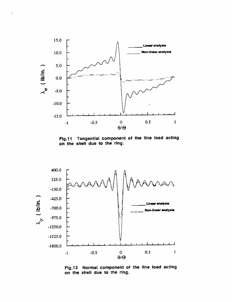
Interacting load distributions
The distributions of the interacting loads between the ring and shell are shown in Figs. 11 and 12. The distribution of
the circumferential component (Fig. 11) is antisymmetric about the origin, and has reduced magnitudes due to the
geometrically nonlinear effect. As shown in Fig. 12, the normal component of the interacting load is an extremum at
the origin, exhibiting a severe gradient there. The negative value of 7_ at the origin indicates that the action of the
ring is to pull the shell radially inward against the action of the pressure to expand the shell outward. The peak normalload intensity is reduced from - 1,674 lb/in in the linear analysis to - 1,045 lh/in in the nonlinear analysis.
The distributions of the interacting loads between the stringer and the shell are shown in Figs. 13 and 14. The distri-
bution of the tangential component is antisymmetric about the origin and has reduced peak magnitudes due to the
geometrically nonlinear effect as shown in Fig. 13. The normal component L_s is maximum at the origin and has a
steep gradient there as shown in Fig. 14. The ma0ti_mam value of normal component is reduced from 484.7 lb/in in the
linearanalysisto320.3lblinthenonlinearanalysis.Notethat the resultant of this normal component vanishes as a
result of Eq. (8).
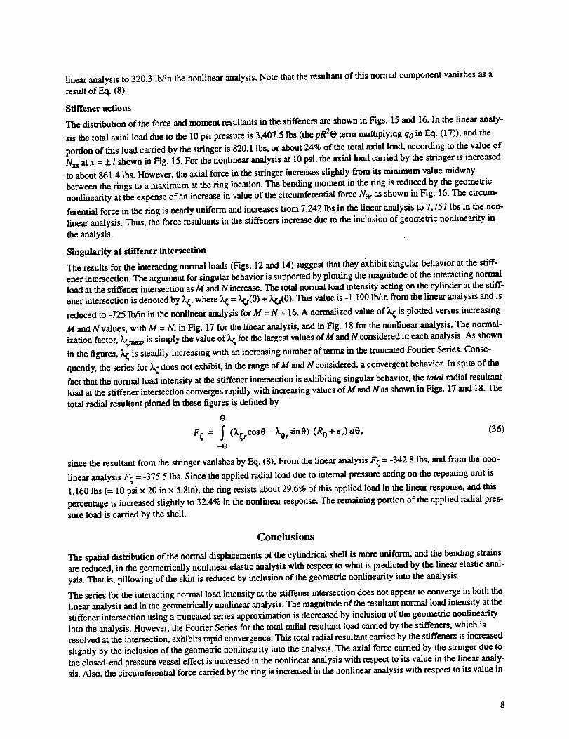
Stiffener actions
The distribution of the force and moment resultants in the stiffeners are shown in Figs. 15 and 16. In the linear analy-
sis the total axial load due to the 10 psi pressure is 3,407.5 lbs (the pR20 term multiplying qo in Eq. (17)), and the
portion of this load carried by the stringer is 820.1 Ibs, or about 24% of the total axial load, according to the value of
Nxs at x = :1:l shown in Fig. 15. For the nonlinear analysis at 10 psi, the axial load carried by the stringer is increased
to about 861.4 lbs. However, the axial force in the stringer increases slightly from its minimum value midway
between the rings to a maximum at the ring location. The bending moment in the ring is reduced by the geometric
nonlinearity at the expense of an increase in value of the circumferential force Nor as shown in Fig. 16. The circum-
ferential force in the ring is nearly uniform and increases from 7,242 lbs in the linear analysis to 7,757 lbs in the non-
linear analysis. Thus, the force resultants in the stiffeners increase due to the inclusion of geometric nonlinearity in
the analysis.
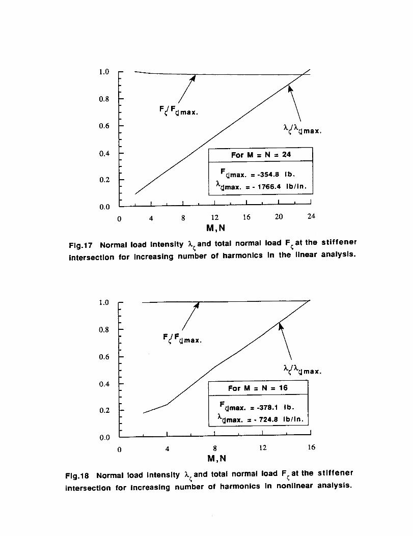
Singularity at stiffener intersection
The results for the interacting normal loads (Figs. 12 and 14) suggest that they e_aibit singular behavior at the stiff-
ener intersection. The argument for singular behavior is supported by plotting the magnitude of the interacting normalload at the stiffener intersection as M and Nincrease. The total normal load intensity acting on the cylinder at the stiff-
ener intersection is denoted by k;, where _ = _(0) + X_s(0). This value is - 1,190 lb/in from the linear analysis and is
reduced to -725 lb/in in the nonlinear analysis for M = N = 16. A normalized value of k_ is plotted versus increasing
M and N values, with M = N, in Fig. 17 for the linear analysis, and in Fig. 18 for the nonlinear analysis. The normal-
ization factor, _,max, is simply the value of _ for the largest values of M and N considered in each analysis. As shown
in the figures, _ is steadily increasing with an increasing number of terms in the truncated Fourier Series. Conse-
quently, the series for _._does not exhibit, in the range of M and N considered, a convergent behavior. In spite of the
fact that the normal load intensity at the stiffener intersection is exhibiting singular behavior, the total radial resultantload at the stiffener intersection converges rapidly with increasing values of M and N as shown in Figs. 17 and 18. The
total radial resultant plotted in these figures is defined by
O
F; = f (_;rcose- XorSin0) (R 0 + er) de, (36)-o
since the resultant from the stringer vanishes by Eq. (8). From the linear analysis F; = -342.8 Ibs, and from the non-
linear analysis F; = -375.5 lbs. Since the applied radial load due to internal pressure acting on the repeating unit is
1,160 lbs (= I0 psi x 20 in x 5.8in), the ring resists about 29.6% of this applied load in the linear response, and this
percentage is increased slightly to 32.4% in the nonlinear response. The remaining portion of the applied radial pres-
sure load is carried by the shell.
Conclusions
The spatial distribution of the normal displacements of the cylindrical shell is more uniform, and the bending strains
ate reduced, in the geometrically nonlinear elastic analysis with respect to what is predicted by the linear elastic anal-
ysis. That is, pillowing of the skin is reduced by inclusion of the geometric nonlinearity into the analysis.
The series for the interacting normal load intensity at the stiffener intersection does not appear to converge in both the
linear analysis and in the geometrically nonlinear analysis. The magnitude of the resultant normal load intensity at the
stiffener intersection using a truncated series approximation is decreased by inclusion of the geometric nonlinearity
into the analysis. However, the Fourier Series for the total radial resultant load carried by the stiffeners, which isresolved at the intersection, exhibits rapid convergence. This total radial resultant carried by the stiffeners is increased
slightly by the inclusion of the geometric nonlinearity into the analysis. The axial force carried by the stringer due tothe closed-end pressure vessel effect is increased in the nonlinear analysis with respect to its value in the linear analy-
sis. Also, the circumferential force carried by the ring i_ increased in the nonlinear analysis with respect to its value in

thelinear analysis. Thus, the stiffeners resist an increased portion of the internal pressure load, accompanied by a
commensurate decrease in the load carded by the shell, when geometric nonlinearity is included into the analysis.
Acknowledgment
This research was sponsored by NASA Grant NAG-I-537. Dr. James H. Starnes, Jr., Head, Aircraft Structures
Branch, Langley Research Center, is the technical monitor.
References
lSanders, J. L., "Nonlinear Theories for Thin Shells;' Quarterly of Applied Mathematics, Vol. 21, No. 1, 1963,
pp. 21-36.
2Sanders, J. L., "An Improved First-Approximation Theory for Thin Shells," NASA Technical Report R-24,
June, 1959.
3Dong, S. B., Pister, K. S., and Taylor, R. L., "On the Theory of Laminated Anisotropic Shells and Plates," Jour-
nal of the Aerospace Sciences, Vol. 29, No. 8, August, 1962, pp. 969-975.
4Wang, J. T-S, and Hsu, T-H., "Discrete Analysis of Stiffened Composite Cylindrical Shells," AIAA Journal, Vol.
23, No. 11, 1985, pp. 1753-1761.
Fig.1 Structural repeating unit of an orthogonally stiffened cylindrical shell subjected to
internal pressure p.
(0)
Fig.2 Distributed line load intensities (Ib/in) acting on the cylindrical shell due to the ring
and stringer.

0.20
0.18
_'_ 0.16
oa
0.14
0.12
0.10
w = 0.2286863 in. ( membrane )
x=o, I , l , I , l ,
-1 -0.8 -0.6 -0.4 -0.2
0/0
Fig.3 Circumferential distribution of the shell's
normal displacement from the linear analysis.
0.20
0.18
'--" 0.16
i_ o.14
0.12
0.10
w = 0.2290210 in. ( membrane )
Tx=O X:-0.251 x=-I
A
-1
, I , I , l , I , I
-0.8 0.6 -0.4 -0.2 0
0/0
Fig.4 Circumferential distribution of the shell's
normal displacement from the nonlinear analysis.
0.20
0.18
"" 0.16
%,,a
3 0.14
0.12
0.10
B
w = 0.2286863 in. ( membrane )
0=-0O=-0A_
0=0I ,
-0.8
I I I , I ,
-0.6 -0.4 -0.2
x/t
Fig.5 Axial distributions of the shell's normal
displacement from the linear analysis.
0.20
0.18
,-_ 0.16
0.14
0.12
0.10
/t
-e=-o
-I
w = 0.2290210 in. ( membrane )
O: - OAOO=O
l , l i I , I ,
-0.8 -0.6 -0.4 -0.2
x/{
Fig.6 Axial distribution of the shell's normal
displacement from the nonlinear analysis.

0.0030
0.0020
Eoe
0.0010
O.OOOO
outer
_ 0.0030
0.0020
0.0010
0.0000inn,f
AtO=-O
i I i I i I i I = I
-0.8 -0.6 -0.4 -0.2 0
x/lor e/B
Fig.7 Circumferential normal strain on the inner andouter shell surfaces from the linear analysis.
-0.0010
-1
outer
/Atx=-I inner
Atg=-e
i I , I I I I I , I
-O.g -0.6 -0.4 -0.2 0
x/I or 0/0
Fig.8 Circumferential normal strain on the Inner andouter shell surfaces from the nonlinear analysis.
0.0010
0.0OO5
£XX
O.OOOO
-0.0005
-0.OOlO
_ef
,, ...... _ .°. _ • .°_.
Mx=-I
At0=-@ inner
I
//
/
\
\
\
I I I I = I , I , I
-1 -o.8 -0.6 -0.4 -0.2 o
x/I or O/O
Fig.9 Axial normal strain on the inner and outershell surfaces from the linear analysis.
0.0010
0.0005
EXX
0.0000
-0.0OO5
-0.0010
outer
I
__ AIx=-I
At O=-@
inner
Fig.lO
I , I i I a I i l
-0.8 -0.6 -0.4 -0.2 0
xll or O/O
Axial normal strain on the inner and outer
shell surfaces from the nonlinear analysis.
m
.Qi
15.0
10.0
5.0
0.0
-5.0
-10.0
-15.0
m
IIII1 IIII
Linearanalysis
___ Non-linearanalysis
-1 -0.5 0 0.5 1
o/e
Fig.11 Tangential component of the line load actingon the shell due to the ring.
400.0
125.0
-150.0
_. -425.0
_/_ -700.0
V
_,, -975.0
-1250.0
-1525.0
-1800.0
m
! Ii , i i I ' ' ' _ I , , , i I i ' ' ' I
-1 -0.5 0 0.5 1
o/e
Fig.12 Normal component of the line load actingon the shell due to the ring.

A
.m
.QI
GPl
e<
40.0
30.0 .20.0 I..i._" analysis
._ " _ Non-linear analysis
10.0
0.0
-10.0
-20.0
-30.0
-40.0 _ j i , I , _ , , I o _ , , I I , ' ' I
-1 -0.5 0 0.5 1
x/I
Fig.13 Tangential component of the line load actingon the shell due to the stringer.
A
,i
.Qm
w
,-<
500.0
400.0
300.0
200.0
100.0
0.0
-100.0
-200.0
-1
__ Linearanalysis
_____ Non-linear analysis
izlll,,J,ll,,,Izl''l
-0.5 0 0.5 1
x/I
Fig.14 Normal component of the line load actingon the shell due to the stringer.

.i!
W
._ 250.00
._ 0.0
W
x -250.0Z
... --- '" "........ 22_ ......
750.0
L_ Nxs Non-linosr analysis
500.0 K "
"" 7"
-500.0 i , , ' I , , , , I , , , , I i , , , I
-1 -0.5 0 0.5 1
x/I
Fig.15 Stringer axial force and bending moment.
A
u!
m
s.--
OA
J_m
o
x
Z
800.0
000.0
400.0
200.0
0.0
-200.0
_/" __ I ineer enalygis
Nor ___-- Nlon-linear analysis
-1
M0r
-0.5 0 0.5 1
o/e
Fig.16 Ring circumferential force and bending moment.
1.0 ----- ./
/F_/Frj max.
0.6X.
0.4
0.2
0.0 _ I , I , I , I _ I , I
0 4 8 12 16 20 24
Fig.17 Normal load Intensity
intersection for increasing number of harmonics in the linear analysis.
M,N
_ and total normal load F¢at the stiffener
1.0
0.8
0.6
0.4
0.2
0.0
0
.
. F_/Frj max.
]Lr.Jmax. = - 724.8 Ib/In.
, I , I J I J I
4 8 12 16
M,N
Fig.18 Normal load intensity _._and total normal load F_ at the stiffener
intersection for increasing number of harmonics in nonlinear analysis.