compression - raymondsraymonds.com.hk/wp-content/uploads/2016/06/ewp02005.pdfbefore compression, a...
TRANSCRIPT
CompressionConnection by Compression . . . . . . . . . . . . . . E2-E5Color-Keyed® Connectors . . . . . . . . . . . . . . . . E6-E9Connectors for Copper Conductor. . . . . . . . E10-E39Cast Copper Connectors for
Copper Conductor . . . . . . . . . . . . . . . . . . E40-E42Flag Connectors for Copper Conductor . . . . . . . E43Flag Connectors for Aluminum Conductor . . . . . E44C-Tap Connectors for Copper
Conductor . . . . . . . . . . . . . . . . . . . . . . . . . E45-E46Copper H-Tap Connectors for Copper
Conductor . . . . . . . . . . . . . . . . . . . . . . . . . E47-E48Aluminum H-Tap Connectors for
Aluminum/Copper Code Conductor (up to 600V) . . . . . . . . . . . . . . . . . . E49
Insulating Covers for H-Taps and C-Taps . . . . . . . . . . . . . . . . . . . . . . . . E50-E51
Wire Joints for Copper Conductor . . . . . . . . . . . . E52Cast Copper Bus Taps for Copper
Conductor. . . . . . . . . . . . . . . . . . . . . . . . . . . . . E53Quick Bus Taps for Copper Conductor . . . . . . . . E54Motor Pigtail Connectors . . . . . . . . . . . . . . . E55-E59High-Amperage Quick Power
Disconnects . . . . . . . . . . . . . . . . . . . . . . . . . . . E60Copper Traction Motor Disconnect Lugs
for Diesel-Electric Locomotives . . . . . . . . . . . . E61Connector Kits. . . . . . . . . . . . . . . . . . . . . . . . . . . E62Connectors for Aluminum/Copper
Code Conductor . . . . . . . . . . . . . . . . . . . . E63-E68Transformer Lug Kits for Aluminum/
Code Conductor . . . . . . . . . . . . . . . . . . . . . . . . E69Pin Connectors for Aluminum/
Copper Code Conductor . . . . . . . . . . . . . . . . . E70Heavy Duty Battery Connectors . . . . . . . . . E71-E75Heavy Duty Battery Cables . . . . . . . . . . . . . E76-E77Tooling for Heavy Duty Battery
Connectors and Conductor . . . . . . . . . . . . . . . E78Connector Tools. . . . . . . . . . . . . E79-E83, E94-E100Smart® Connector Tools . . . . . . . . . . . . . . . . E84-E85Installation Tools . . . . . . . . . . . . . . . E86, E101-E102Batpac® Battery Powered Compression
and Cutting Tools . . . . . . . . . . . . . . . . . . . E87-E93Sealants and Lubricants . . . . . . . . . . . . . . . . . . E103Installing Dies . . . . . . . . . . . . . . . . . . . . . E104-E106Connector, Tool and Die Chart. . . . . . . . . E107-E108
for Copper H-Taps . . . . . . . . . . . . . . . . . . . . . E109for Standard C-Taps . . . . . . . . . . . . . . . . . . . . E110for Large C-Taps . . . . . . . . . . . . . . . . . . . . . . . E111
Tool Services . . . . . . . . . . . . . . . . . . . . . . . . . . . E112
E
412031.E01 CK 3/5 3/13/03 8:21 PM Page 1

E2 © 2002 Thomas & Betts Corporation. Specifications are subject to change without notice. www.tnb.com
Connection by Compression
The Thomas & Betts Method Is Better.
The Thomas & Betts method ofinstalling compression connectors onpower cables is designed to provide ahigh degree of reliability in electricalwiring. This method allows electrical
workers to make installations with littleeffort and at a considerable savings intime. The benefit, of course, is a highquality connection at a low installedcost.
Just Four Easy Steps to a Perfect Connection
Strip the insulation carefully to avoid nicking or cutting conductors(wire brush if required).
StrandsCut
NickedStrands
GoodStrip
Strip the insulation to the proper length so that conductors can be fullyinserted into the connector barrel.
Strip Length Too Long
Strip Length Too Short
Strip Length Just Right
1
Determine the proper Color-Keyed® Connector for the cable size beingused. Connectors are marked to show cable size.2
• Connectors marked with just cablesize or CU should be used on cop-per conductors only.
• Connectors marked “AL9”* with thecable size should be used on alumi–num conductors only.
• Connectors marked “AL9CU” withthe cable size may be used on thealuminum or copper conductors.
* Aluminum lugs with a “9” indicate90°C rating.
Cable Size
Wire Stripper shown is Part No. BCS8-40.
Compression
E
Colo
r-Ke
yed®
412031.E01 CK 3/5 3/13/03 8:21 PM Page 2
© 2002 Thomas & Betts Corporation. Specifications are subject to change without notice. www.tnb.com E3
Connection by Compression
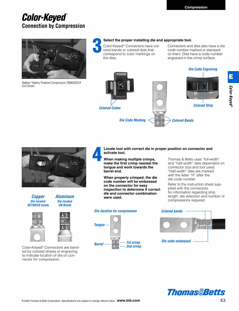
Select the proper installing die and appropriate tool.3
Colored Codes
Colored BandsDie Code Marking
Colored Strip
Die Code Engraving
Locate tool with correct die in proper position on connector and activate tool.4
Color-Keyed® Connectors have col-ored bands or colored dots thatcorrespond to color markings onthe dies.
Connectors and dies also have a diecode number marked or stampedon them. Dies have a code numberengraved in the crimp surface.
When making multiple crimps,make the first crimp nearest thetongue and work towards thebarrel end.
When properly crimped, the diecode number will be embossed on the connector for easyinspection to determine if correctdie and connector combinationwere used.
Thomas & Betts uses “full-width”and “half-width” dies dependent onconnector size and tool used.“Half-width” dies are markedwith the letter “H” after thedie code number.Refer to the instruction sheet sup-plied with the connectorsfor information regarding striplength, die selection and number ofcompressions required.
AluminumDie locatedON Bands
CopperDie located
BETWEEN bands
Barrel
Tongue
1st crimp2nd crimp
Die location for compression Colored bands
Die code embossed
Color-Keyed® Connectors are band-ed by colored stripes or engravingto indicate location of die on con-nector for compression.
Battpac® Battery Powered Compression TBM62BSCRtool shown.
Compression
E
Color-Keyed®
412031.E01 CK 3/5 3/13/03 8:21 PM Page 3

Before compression,a typical cross sec-tion of cable andconnector consistsof about 75% metaland 25% air.
After air compressionby the T&B Method,the cross sectionlooks like this, 100%metal with virtually noair spaces.
Connection by Compression
The T&B method utilizing compressiontools with matching dies forms the con-nector and conductor into a solid,homogenous mass to provide an opti-mum electrical bond between connec-tor and conductor.Thomas & Betts method dies aredesigned to produce a circumferential,hex- or diamond-shaped compressionrather than a simple indent. Precisiondies are an integral part of the Thomas& Betts method. The precision hard-ened steel dies exert tremendous, con-trolled pressure on the connector andconductor. The dies compress the con-nector around the cable, converting
the round strands to hexagonal or dia-mond shapes and forming the strandsand connector into a solid mass. Eachdie is designed so that all conductorsreceive the same amount of compres-sion force.The circumferential compression cre-ates a large area of high pressure con-tact between cable and connectorwhich, in turn, assures high conductivi-ty, low resistance, and high pullout val-ues which exceed UL requirements.These features result in a permanent,low installed cost connection. You caninstall it, and forget it.
Precision Dies From a Solid Homogenous Mass…
Color-Keyed® connectors not only iden-tify the correct installing die to be usedfor positive compressions, but alsoindicate the proper placement of thedie on the connector. This is done bythe bands of color on the connector
which match the color on the dies.Compression is made between or onthese color bands. The color name isalso spelled on the connector as anadded means of identification.
Thomas & Betts’ System Tells You Where to Place the Installing Die.
Dies that are used in Thomas & Bettshand and hydraulic tools contain the“die code” numbers which are engravedon the compression surface of the die.Under compression, this numberbecomes embossed on the completedconnection for inspection purposes.
The inspector compares the die codenumber embossed on the connectorwith the die table to ensure that theproper connector was compressedwith the correct die for that particularsize conductor.
Thomas & Betts Dies Offer Inspection Capability.
E4 © 2002 Thomas & Betts Corporation. Specifications are subject to change without notice. www.tnb.com
Colored bands
Die code embossed
AluminumDie locatedON Bands
CopperDie located
BETWEEN bands
Color-Keyed® Connectors are band-ed by colored stripes or engravingto indicate location of die on con-nector for compression.
Compression
E
Colo
r-Ke
yed®
412031.E01 CK 3/5 3/13/03 8:21 PM Page 4

Thomas & Betts Method Components Meet Industry Standards.
Depending on the application, allThomas & Betts copper connectorsmeet U.L. Std. 486A for code strandedand 24 gauge flex, CSA Std. C22.2,No. 65.600 V. requirements for powerand U.L. Std. 467, CSA Std. 22.2 No.0.4 requirements for direct buriedgrounding.
T&B method connectors are avail-able in a range of sizes and styles toaccommodate No. 8AWG through1000 kcmil and larger copper or 2000kcmil and larger aluminum cable. Theymay be compressed on cable witheither manual or hydraulic tools. Theyare offered with standard length orlong barrels, with one bolt or two boltholes, or in two-way styles, for splicingapplications. Two-way connectors arecompact, providing high pullout valueswith low resistance.
Color-Keyed® two-hole lugs are idealfor bus bar applications that require twobolts to prevent lug rotation.
The T&B method is the most effi-cient, highest quality connection thathas been engineered and delivers thebest electrical performance and high-est reliability.
T&B Compression Connectors elimi-nate risk of problems relating to looseconnections when installed properly.
Quality Tooling With the Shure-Stake® Mechanism
T&B manual tools with the exclusive,Shure-Stake® mechanism take theguesswork out of making compressionconnections. The Shure-Stake® mecha-nism provides a full cycle compressionstroke every time. Once the stroke hasstarted, the tool will not release theconnector until the proper amount offorce has been applied. This is yourassurance of a fully compressed con-nection. T&B compression tools devel-op uniform, controlled pressure toeach connector within their size range.Thomas & Betts offers electric andbattery-powered hydraulic pumps witha Shure-Stake® feature that guaranteesa full cycle compression.
High Grade Materials Incorporated In Thomas & Betts Method
Low installed cost connections ofsuperior quality can be achieved onlythrough the use of high grade compo-nents. That is an important part of theT&B method – quality products youcan depend on.
Copper Color-Keyed® connectorsare made of high conductivity wroughtcopper, and are electro-tin plated toprevent corrosion and to improve con-ductivity. Thomas & Betts Color-Keyed® connectors offer the thickesttin-plating in the industry. Other cop-per connectors for heavy duty use andgrid grounding applications are madeof high conductivity cast copper,bright finished.
High conductivity cast aluminumconnectors are available for heavyduty application.
Connection by Compression
© 2002 Thomas & Betts Corporation. Specifications are subject to change without notice. www.tnb.com E5
TBM62BSCRSingle-handed battery-powered compressiontool, features rotatinghead and comfortablebalance. For connectorsup to 500MCM CU,350MCM AL.
Pumpac® IIThe newest battery-powered hydraulic pump, rated for10,000 PSI. Portable power for allT&B hydraulic heads, using justtwo 14.4 rechargeable batteries.
TBM6SHand-operated crimpingtool, features Shure-Stake®
mechanism to insure acompleted crimp. For connectors up to 500MCM CU, 350 MCM AL.
Compression
E
Color-Keyed®
412031.E01 CK 3/5 3/13/03 8:21 PM Page 5
Color-Keyed® Connectors
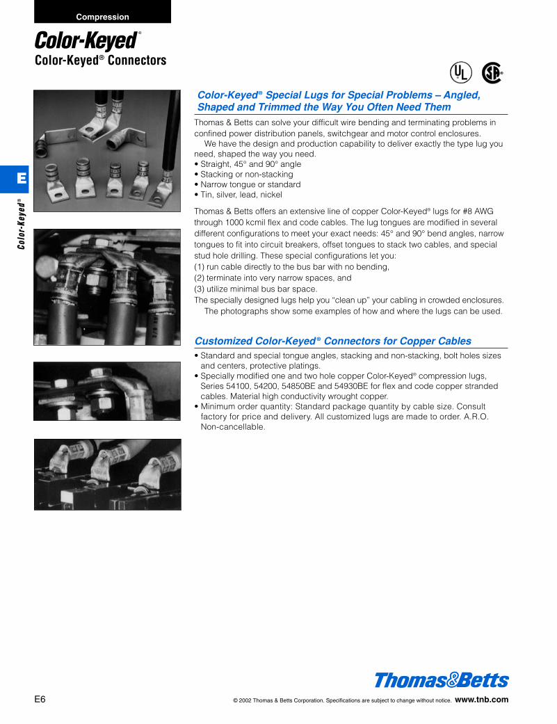
Color-Keyed ® Special Lugs for Special Problems – Angled,Shaped and Trimmed the Way You Often Need Them
Thomas & Betts can solve your difficult wire bending and terminating problems inconfined power distribution panels, switchgear and motor control enclosures.
We have the design and production capability to deliver exactly the type lug youneed, shaped the way you need.• Straight, 45° and 90° angle• Stacking or non-stacking• Narrow tongue or standard• Tin, silver, lead, nickel
Thomas & Betts offers an extensive line of copper Color-Keyed® lugs for #8 AWGthrough 1000 kcmil flex and code cables. The lug tongues are modified in severaldifferent configurations to meet your exact needs: 45° and 90° bend angles, narrowtongues to fit into circuit breakers, offset tongues to stack two cables, and specialstud hole drilling. These special configurations let you:(1) run cable directly to the bus bar with no bending,(2) terminate into very narrow spaces, and(3) utilize minimal bus bar space.The specially designed lugs help you “clean up” your cabling in crowded enclosures.
The photographs show some examples of how and where the lugs can be used.
Customized Color-Keyed ® Connectors for Copper Cables• Standard and special tongue angles, stacking and non-stacking, bolt holes sizes
and centers, protective platings.• Specially modified one and two hole copper Color-Keyed® compression lugs,
Series 54100, 54200, 54850BE and 54930BE for flex and code copper strandedcables. Material high conductivity wrought copper.
• Minimum order quantity: Standard package quantity by cable size. Consult factory for price and delivery. All customized lugs are made to order. A.R.O.Non-cancellable.
®
®
E6 © 2002 Thomas & Betts Corporation. Specifications are subject to change without notice. www.tnb.com
Compression
E
Colo
r-Ke
yed®
412031.E01 CK 3/5 3/13/03 8:21 PM Page 6

Color-Keyed® Connectors
Order From
Catalog No. _______________________ Qty. _______________________(For 54100, 54200, 54800 & 54900 Series Copper Lugs Only)
Design Controls and RequirementsAll “MADE-UP” catalog numbers start with a standard or basic catalog number and are followed by the customer required extra
features: tongue shape, bolt hole size, distance between bolt holes, stacking, plating and inspection hole (peep hole). A codeletter or a number has been assigned to each extra feature. See CODE TABLE.
NOTES: 1) Lack of any of the extra features on the “MADE-UP” catalog number means that the standard Cat. No. features areprevalent.
2) If either bolt hole size or distance between bolt holes needs to be changed from standard Cat. No., both code numbers willappear on the “MADE-UP” Cat. No. (See example below)
Cat. No. 54212UB0416BSP
54212
2 hole4/0 cu. lug
basic cat. no.
UB
90°bend
04
1/4"bolt hole
16
1" holespacing
B
bottomstack
CODE TABLE
Tongue Shape Bolt Holes Bolt Stacking Finish Inspection Hole Inspection HoleHole Centers (Plating) (Long Barrel) (Short Barrel)
Type Code Size .020 Code Distance .015 Code Type Code Type 1 Code I.D. Code I.D. Code
45° UF #8 .173 02 d" 08 Top T** Silver Plate SP Peep Hole PH Blind End BE90° UB #10 .204 03 e" 10 Bottom B Lead Plate LP
Blank BT b" .281 04 f" 12 Nickel Plate NP(No Bolt Hole) j" .344 05 g" 14 Plain Finish PF
c" .406 06 1" 16 No Marking NMd" .531 08 1a" 18 Not QTP ife" .656 10 1b" 20 suffix otherf" .812 12 1c" 22 than - PF org" .937 14 1d" 24 standard1" 1.062 16 1e" 26 tin plate
1f" 28*1g" 30*2" 32
* These bolt centers not available for bolt holes larger than m".** Not required for 45° & 90° Top Stacking.
Cable Code □Weld □
□ #8 □ #6 □ #4
□ #2 □ #1 □ 1/0
□ 2/0 □ 3/0 □ 4/0
□ 250 kcmil & up (Code Only)
Bolt/Stud Size
Peep Hole Yes
No
Tongue Width
Hole Offset
“If required”
Bolt Spacing Wrench Clearance
Barrel I.D.
“For Blank Tongue”
Tongue Length
Barrel O.D.Tongue Thickness
Barrel Length
Plus Transition
Longor
Short
© 2002 Thomas & Betts Corporation. Specifications are subject to change without notice. www.tnb.com E7
Compression
E
Color-Keyed®
412031.E01 CK 3/5 3/13/03 8:21 PM Page 7
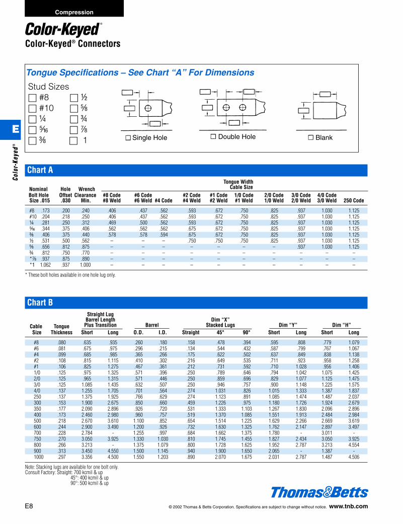
Tongue Specifications – See Chart “A” For Dimensions
Stud Sizes□ #8 □ d□ #10 □ e□ b □ f□ j □ g□ c □ 1 Single Hole Double Hole Blank
Chart ATongue Width
Nominal Hole Wrench Cable SizeBolt Hole Offset Clearance #8 Code #6 Code #2 Code #1 Code 1/0 Code 2/0 Code 3/0 Code 4/0 CodeSize .015 .030 Min. #8 Weld #6 Weld #4 Code #4 Weld #2 Weld #1 Weld 1/0 Weld 2/0 Weld 3/0 Weld 250 Code
#8 .173 .200 .240 .406 .437 .562 .593 .672 .750 .825 .937 1.030 1.125#10 .204 .218 .250 .406 .437 .562 .593 .672 .750 .825 .937 1.030 1.125b .281 .250 .312 .469 .500 .562 .593 .672 .750 .825 .937 1.030 1.125j .344 .375 .406 .562 .562 .562 .675 .672 .750 .825 .937 1.030 1.125c .406 .375 .440 .578 .578 .594 .675 .672 .750 .825 .937 1.030 1.125d .531 .500 .562 – – – .750 .750 .750 .825 .937 1.030 1.125e .656 .812 .875 – – – – – – – .937 1.030 1.125f .812 .750 .770 – – – – – – – – – –*g .937 .875 .890 – – – – – – – – – –*1 1.062 .937 1.000 – – – – – – – – – –
* These bolt holes available in one hole lug only.
Chart BStraight Lug
Barrel Length Dim “X”Cable Tongue Plus Transition Barrel Stacked Lugs Dim “Y” Dim “H”Size Thickness Short Long O.D. I.D. Straight 45° 90° Short Long Short Long
#8 .080 .635 .935 .260 .180 .158 .478 .394 .595 .808 .779 1.079#6 .081 .675 .975 .296 .215 .134 .544 .432 .587 .799 .767 1.067#4 .099 .685 .985 .365 .266 .175 .622 .502 .637 .849 .838 1.138#2 .108 .815 1.115 .410 .302 .216 .649 .535 .711 .923 .958 1.258#1 .106 .825 1.275 .467 .361 .212 .731 .592 .710 1.028 .956 1.4061/0 .125 .975 1.325 .571 .396 .250 .789 .646 .794 1.042 1.075 1.4252/0 .125 .965 1.315 .571 .446 .250 .859 .696 .829 1.077 1.125 1.4753/0 .125 1.085 1.435 .632 .507 .250 .946 .757 .900 1.148 1.225 1.5754/0 .137 1.255 1.705 .701 .564 .274 1.031 .826 1.015 1.333 1.387 1.837250 .137 1.375 1.925 .766 .629 .274 1.123 .891 1.085 1.474 1.487 2.037300 .153 1.900 2.675 .850 .660 .459 1.226 .975 1.180 1.726 1.924 2.679350 .177 2.090 2.896 .926 .720 .531 1.333 1.103 1.267 1.830 2.096 2.896400 .173 2.460 2.980 .960 .757 .519 1.370 1.085 1.551 1.913 2.484 2.984500 .218 2.670 3.610 1.100 .852 .654 1.514 1.225 1.629 2.266 2.669 3.619600 .244 2.900 3.490 1.200 .926 .732 1.630 1.325 1.762 2.147 2.897 3.497700 .228 2.784 - 1.255 .997 .684 1.662 1.375 1.780 - 3.011 -750 .270 3.050 3.925 1.330 1.030 .810 1.745 1.455 1.827 2.434 3.050 3.925800 .266 3.213 - 1.375 1.079 .800 1.728 1.625 1.952 2.787 3.213 4.554900 .313 3.450 4.550 1.500 1.145 .940 1.900 1.650 2.065 - 1.387 -1000 .297 3.356 4.500 1.550 1.203 .890 2.070 1.675 2.031 2.787 1.487 4.506
Note: Stacking lugs are available for one bolt only.Consult Factory: Straight: 700 kcmil & up
45°: 400 kcmil & up90°: 500 kcmil & up
E8 © 2002 Thomas & Betts Corporation. Specifications are subject to change without notice. www.tnb.com
Color-Keyed® Connectors
Compression
E
Colo
r-Ke
yed®
412031.E01 CK 3/5 3/13/03 8:21 PM Page 8

Chart CTongue Width .030
Code Cable SizeBoltHole 300 kcmil 350 kcmil 400 kcmil 500 kcmil 600 kcmil 1325/24 700 750 800 900 1000Size 4/0 Weld 400 Weld 500 Weld kcmil kcmil kcmil kcmil kcmil
#8 – – – – – – – – – – –#10 – – – – – – – – – – –b 1.250 1.355 1.410 1.605 1.745 1.805 1.840 1.935 2.010 2.180 2.265j 1.250 1.355 1.410 1.605 1.745 1.805 1.840 1.935 2.010 2.180 2.265c 1.250 1.355 1.410 1.605 1.745 1.805 1.840 1.935 2.010 2.180 2.265d 1.250 1.355 1.410 1.605 1.745 1.805 1.840 1.935 2.010 2.180 2.265e 1.250 1.355 1.410 1.605 1.745 1.805 1.840 1.935 2.010 2.180 2.265f 1.250 1.355 1.410 1.605 1.745 1.805 1.840 1.935 2.010 2.180 2.265
*g – – – 1.605 1.745 1.805 1.840 1.935 2.010 2.180 2.265*1 – – – – 1.745 1.805 1.840 1.935 2.010 2.180 2.265
Formula 1 = (.125 + 2 (OD) + .037 – Tongue Thickness)
© 2002 Thomas & Betts Corporation. Specifications are subject to change without notice. www.tnb.com E9
Color-Keyed® Connectors
Compression
E
Color-Keyed®
412031.E01 CK 3/5 3/13/03 8:21 PM Page 9
®
®
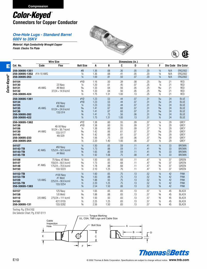
CableInspectionHole Bolt Size
E C
F
A
DB
Tongue Marking:UL, CSA, T&B Logo and Cable Size
One-Hole Lugs - Standard Barrel600V to 35KVMaterial: High Conductivity Wrought CopperFinish: Electro Tin Plate
Connectors for Copper Conductor
Wire Size Dimensions (in.)Cat. No. Code Flex Bolt Size A B C D E F Die Code Die Color
256-30695-1351 #8 1.36 .68 .36 .05 .20 b N/A ERG2002256-30695-1352 #14-10 AWG b 1.36 .68 .41 .05 .20 b N/A ERG2002256-30695-263 b 1.69 .81 .50 .07 .20 b N/A ERG2002
54104 #10 1.16 .50 .39 .08 .25 r 21 RED54130 23 Navy b 1.20 .61 .45 .07 .25 b 21 RED54131 #8 AWG #8 Weld j 1.33 .64 .56 .05 .25 s 21 RED54132 37/24 = 14.9 kcmil c 1.33 .64 .56 .05 .25 s 21 RED256-30695-424 d 1.75 1.31 1.00 .13 .25 d 21 RED
256-30695-1361 #12 1.23 .53 .44 .07 .31 r 24 BLUE54134 #10 1.23 .53 .44 .07 .31 r 24 BLUE54105
#30 Navyb 1.23 .53 .44 .07 .31 r 24 BLUE
54135 #6 AWG#6 Weld
j 1.41 .67 .60 .07 .31 j 24 BLUE54136
61/24 = 24.6 kcmilc 1.41 .67 .60 .07 .31 j 24 BLUE
256-30695-282133/.014
c 1.41 .75 .56 .06 .31 j 24 BLUE256-30695-422 d 1.75 1.31 1.00 .13 .31 d 24 BLUE
256-30695-1362 #12 1.38 .60 .55 .09 .37 b 29 GREY54138 #10 1.38 .60 .55 .09 .37 b 29 GREY54106
40-50 Navyb 1.38 .60 .55 .09 .37 b 29 GREY
54139 #4 AWG91/24 = 36.7 kcmil
j 1.42 .66 .61 .07 .37 j 29 GREY54140
133/.0177c 1.42 .66 .61 .07 .37 j 29 GREY
256-30695-23349/.029
c 1.56 .75 .59 .06 .37 j 29 GREY256-30695-264 d 2.20 1.40 1.00 .06 .37 d 29 GREY
54107 b 1.50 .65 .59 .11 .41 b 33 BROWN54142-TB #60 Navy j 1.73 .88 .59 .11 .41 c 33 BROWN54143-TB #2 AWG 125/24 = 50.5 kcmil c 1.65 .80 .59 .11 .41 c 33 BROWN54145-TB #4 Weld d 1.92 1.08 .75 .08 .41 d 33 BROWN
54108 75 Navy, #2 Weld b 1.50 .65 .68 .11 .47 b 37 GREEN54147
#1 AWG150/24 = 60.5 kcmil j 1.73 .93 .68 .11 .47 c 37 GREEN
54148 175/24 = 70.6 kcmil c 1.78 .98 .68 .11 .47 c 37 GREEN54150 133/.0223 d 2.10 1.25 .76 .11 .47 d 37 GREEN
54152-TB b 1.60 .65 .75 .13 .52 b 42 PINK54153-TB
#100 Navyj 1.83 .88 .75 .13 .52 c 42 PINK
54109 1/0 AWG#1 Weld
c 1.88 .93 .75 .13 .52 c 42 PINK54155-TB
225/24 = 90.8 kcmild 2.20 1.25 .75 .13 .52 d 42 PINK
256-30695-1383133/.0254
e 2.54 1.50 .88 .13 .52 e 42 PINK
54157 125 Navy b 1.65 .65 .83 .13 .57 b 45 BLACK54158 1/0 Weld j 1.88 .88 .83 .13 .57 c 45 BLACK54110 2/0 AWG 275/24 = 111 kcmil c 1.93 .93 .83 .13 .57 c 45 BLACK54160 427/.0155 d 2.25 1.25 .83 .13 .57 d 45 BLACK256-30695-131 133/.0282 e 2.56 1.50 .83 .13 .57 e 45 BLACK
Tooling: Pg. E78-E102Die Selector Chart: Pg. E107-E111
E10 © 2002 Thomas & Betts Corporation. Specifications are subject to change without notice. www.tnb.com
Compression
E
Colo
r-Ke
yed®
412031.E01 CK 3/5 3/13/03 8:21 PM Page 10

One-Hole Lugs - Standard Barrel600V to 35KV (continued)Material: High Conductivity Wrought CopperFinish: Electro Tin Plate
®
®
Connectors for Copper Conductor
CableInspectionHole Bolt Size
E C
F
A
DB
Tongue Marking:UL, CSA, T&B Logo and Cable Size
Wire Size Dimensions (in.)Cat. No. Code Flex Bolt Size A B C D E F Die Code Die Color
54162-TB 150 Navy, 2/0 Weld b 1.75 .65 .92 .13 .63 b 50 ORANGE54163-TB 325/24 = 131 kcmil j 1.98 .88 .92 .13 .63 c 50 ORANGE54111 3/0 AWG 133/.0316, 259/.0227 c 2.03 .93 .92 .13 .63 c 50 ORANGE54165-TB 427/.0177 d 2.35 1.25 .92 .13 .63 d 50 ORANGE
54167 b 1.90 .65 1.03 .14 .70 b 54 PURPLE54168
200 Navyj 2.13 .87 1.03 .14 .70 c 54 PURPLE
54112 4/0 AWG3/0 Weld
c 2.18 .93 1.03 .14 .70 c 54 PURPLE54170
450/24 = 182 kcmild 2.50 1.25 1.03 .14 .70 d 54 PURPLE
256-30695-1174703/.0154
f 2.86 1.56 1.03 .14 .70 f 54 PURPLE
58161 4/0 Weld b 2.23 .78 1.25 .15 .79 c 62 YELLOW58162 550/24 = 222 kcmil j 2.33 .88 1.25 .15 .79 c 62 YELLOW58163 133/.0399 c 2.38 .93 1.25 .15 .79 c 62 YELLOW58165 259/.0286 d 2.76 1.25 1.25 .15 .79 d 62 YELLOW58166 637/.0183 e 3.03 1.58 1.25 .15 .79 e 62 YELLOW
54172-TB b 2.00 .65 1.13 .14 .77 d 62 YELLOW54173 j 2.23 .88 1.13 .14 .77 c 62 YELLOW54174
250 kcmil 250 Navyc 2.28 .93 1.13 .14 .77 c 62 YELLOW
54113 d 2.60 1.25 1.13 .14 .77 d 62 YELLOW
250 Weld, 58168 650/24 = 262 kcmil, d 2.70 1.25 1.25 .15 .85 d 66 WHITE
259/.0311, 703/.0189
54178 j 2.33 .88 1.25 .15 .85 c 66 WHITE54179 c 2.43 .93 1.25 .15 .85 c 66 WHITE54114
300 kcmil 300 Navyd 2.70 1.25 1.25 .15 .85 d 66 WHITE
54181 e 3.03 1.58 1.25 .15 .85 e 66 WHITE
300 Weld, 259/.034, 58171 427/.0265, 889/.0183 d 2.85 1.25 1.36 .18 .93 d 71 RED
775/24 = 313 kcmil
256-30695-112 c 2.90 1.25 1.36 .18 .93 d 71 RED54115 350 kcmil 350 Navy d 2.85 1.25 1.36 .18 .93 d 71 RED54183 e 3.21 1.58 1.36 .18 .93 e 71 RED
350 Weld, 259/.0368, 58174 427/.0285, 703/.0224, d 3.35 1.25 1.61 .22 1.09 d 76 BLUE
889/.0201
54116 d 3.20 1.25 1.41 .17 .96 d 76 BLUE54185
400 kcmil 400 Navye 3.53 1.58 1.41 .17 .96 e 76 BLUE
Tooling: Pg. E78-E102Die Selector Chart: Pg. E107-E111
© 2002 Thomas & Betts Corporation. Specifications are subject to change without notice. www.tnb.com E11
Compression
E
Color-Keyed®
412031.E01 CK 3/5 3/13/03 8:21 PM Page 11

One-Hole Lugs - Standard Barrel600V to 35KV (continued)Material: High Conductivity Wrought CopperFinish: Electro Tin Plate
®
®
Connectors for Copper Conductor
CableInspectionHole Bolt Size
E C
F
A
DB
Tongue Marking:UL, CSA, T&B Logo and Cable Size
Wire Size Dimensions (in.)Cat. No. Code Flex Bolt Size A B C D E F Die Code Die Color
400 Weld256-30695-1403 925/24 = 373 kcmil c 3.31 1.31 1.61 .22 1.04 e 80 N/A58177 259/.0393 d 3.31 1.25 1.61 .22 1.04 d 80 N/A
or 427/.0306
256-30695-339 c 3.10 1.00 1.61 .22 1.10 c 87 BROWN54118 500 kcmil 500 Navy d 3.30 1.25 1.61 .22 1.10 d 87 BROWN54187 e 3.63 1.58 1.61 .22 1.10 e 87 BROWN
1100/24 = 444 kcmil,58180 500 Weld, 259/.0417, e 3.79 1.58 1.75 .24 1.20 e 94 GREEN
427/.0325, 703/.0253
256-30695-1054 g 3.96 1.81 1.75 .24 1.20 m 94 GREEN256-30695-1370 600 kcmil d 3.65 1.44 1.75 .24 1.20 m 94 GREEN54120 e 3.79 1.58 1.75 .24 1.20 e 94 GREEN
54122-TB 700 kcmil e 3.68 1.58 1.84 .23 1.26 e 99 PINK
256-30695-1404 c 3.29 1.29 1.81 .28 1.25 y 99 PINK256-30695-1405 1325/24 = 535 kcmil d 3.29 1.29 1.81 .28 1.25 y 99 PINK256-30695-840 427/.0342 d 4.00 1.69 1.81 .28 1.25 m 99 PINK58182 e 3.83 1.58 1.81 .28 1.25 e 99 PINK
256-30695-193 750 kcmil d 4.00 1.69 1.94 .27 1.33 m 106 BLACK54123-TB e 3.87 1.58 1.94 .27 1.33 e 106 BLACK256-30695-937 g 4.10 1.88 1.94 .27 1.33 g 106 BLACK
58184 1600/24 = 646 kcmil e 3.80 1.58 1.94 .27 1.33 e 106 BLACK
54124-TB 800 kcmil 800 Navy e 4.04 1.58 2.01 .27 1.38 e 107 ORANGE
256-30695-843 900 kcmil 1925/24 = 777 kcmil d 4.31 1.81 2.17 .31 1.50 g 115 YELLOW54126 e 4.15 1.58 2.17 .31 1.50 e 115 YELLOW
54128 1000 kcmil 1000 Navy e 4.09 1.58 2.27 .30 1.55 e 125 N/A
Tooling: Pg. E78-E102Die Selector Chart: Pg. E107-E111
E12 © 2002 Thomas & Betts Corporation. Specifications are subject to change without notice. www.tnb.com
Compression
E
Colo
r-Ke
yed®
412031.E01 CK 3/5 3/13/03 8:21 PM Page 12
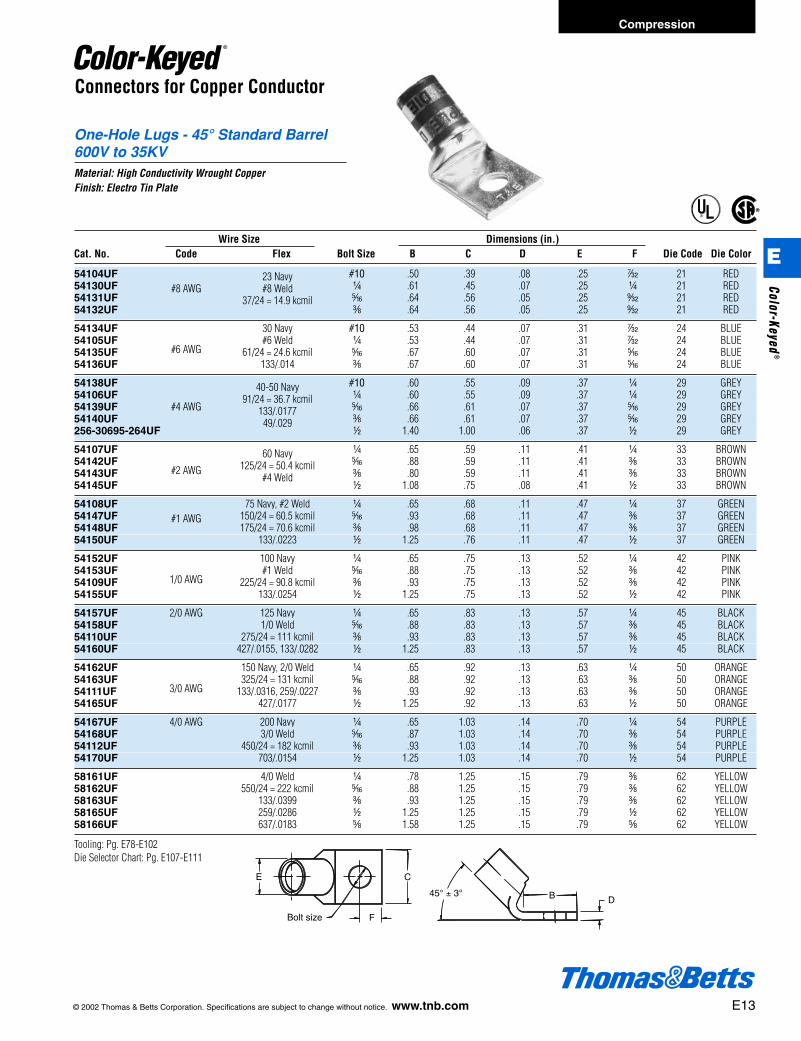
One-Hole Lugs - 45° Standard Barrel600V to 35KVMaterial: High Conductivity Wrought CopperFinish: Electro Tin Plate
®
®
E
Bolt size
C
F
45° ± 3°DB
Connectors for Copper Conductor
Wire Size Dimensions (in.)Cat. No. Code Flex Bolt Size B C D E F Die Code Die Color
54104UF #10 .50 .39 .08 .25 r 21 RED54130UF
23 Navyb .61 .45 .07 .25 b 21 RED
54131UF#8 AWG #8 Weld
j .64 .56 .05 .25 s 21 RED54132UF
37/24 = 14.9 kcmilc .64 .56 .05 .25 s 21 RED
54134UF 30 Navy #10 .53 .44 .07 .31 r 24 BLUE54105UF
#6 AWG#6 Weld b .53 .44 .07 .31 r 24 BLUE
54135UF 61/24 = 24.6 kcmil j .67 .60 .07 .31 j 24 BLUE54136UF 133/.014 c .67 .60 .07 .31 j 24 BLUE
54138UF #10 .60 .55 .09 .37 b 29 GREY54106UF
40-50 Navyb .60 .55 .09 .37 b 29 GREY
54139UF #4 AWG91/24 = 36.7 kcmil
j .66 .61 .07 .37 j 29 GREY54140UF
133/.0177c .66 .61 .07 .37 j 29 GREY
256-30695-264UF49/.029
d 1.40 1.00 .06 .37 d 29 GREY
54107UF b .65 .59 .11 .41 b 33 BROWN54142UF
#2 AWG
60 Navyj .88 .59 .11 .41 c 33 BROWN
54143UF125/24 = 50.4 kcmil
c .80 .59 .11 .41 c 33 BROWN54145UF
#4 Weldd 1.08 .75 .08 .41 d 33 BROWN
54108UF 75 Navy, #2 Weld b .65 .68 .11 .47 b 37 GREEN54147UF 150/24 = 60.5 kcmil j .93 .68 .11 .47 c 37 GREEN54148UF
#1 AWG175/24 = 70.6 kcmil c .98 .68 .11 .47 c 37 GREEN
54150UF 133/.0223 d 1.25 .76 .11 .47 d 37 GREEN
54152UF 100 Navy b .65 .75 .13 .52 b 42 PINK54153UF
1/0 AWG#1 Weld j .88 .75 .13 .52 c 42 PINK
54109UF 225/24 = 90.8 kcmil c .93 .75 .13 .52 c 42 PINK54155UF 133/.0254 d 1.25 .75 .13 .52 d 42 PINK
54157UF 2/0 AWG 125 Navy b .65 .83 .13 .57 b 45 BLACK54158UF 1/0 Weld j .88 .83 .13 .57 c 45 BLACK54110UF 275/24 = 111 kcmil c .93 .83 .13 .57 c 45 BLACK54160UF 427/.0155, 133/.0282 d 1.25 .83 .13 .57 d 45 BLACK
54162UF 150 Navy, 2/0 Weld b .65 .92 .13 .63 b 50 ORANGE54163UF
3/0 AWG325/24 = 131 kcmil j .88 .92 .13 .63 c 50 ORANGE
54111UF 133/.0316, 259/.0227 c .93 .92 .13 .63 c 50 ORANGE54165UF 427/.0177 d 1.25 .92 .13 .63 d 50 ORANGE
54167UF 4/0 AWG 200 Navy b .65 1.03 .14 .70 b 54 PURPLE54168UF 3/0 Weld j .87 1.03 .14 .70 c 54 PURPLE54112UF 450/24 = 182 kcmil c .93 1.03 .14 .70 c 54 PURPLE54170UF 703/.0154 d 1.25 1.03 .14 .70 d 54 PURPLE
58161UF 4/0 Weld b .78 1.25 .15 .79 c 62 YELLOW58162UF 550/24 = 222 kcmil j .88 1.25 .15 .79 c 62 YELLOW58163UF 133/.0399 c .93 1.25 .15 .79 c 62 YELLOW58165UF 259/.0286 d 1.25 1.25 .15 .79 d 62 YELLOW58166UF 637/.0183 e 1.58 1.25 .15 .79 e 62 YELLOW
Tooling: Pg. E78-E102Die Selector Chart: Pg. E107-E111
© 2002 Thomas & Betts Corporation. Specifications are subject to change without notice. www.tnb.com E13
Compression
E
Color-Keyed®
412031.E01 CK 3/5 3/13/03 8:21 PM Page 13
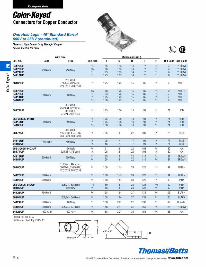
E
Bolt size
C
F
45° ± 3°DB
One Hole Lugs - 45° Standard Barrel600V to 35KV (continued)Material: High Conductivity Wrought CopperFinish: Electro Tin Plate
®
®
Connectors for Copper Conductor
E14 © 2002 Thomas & Betts Corporation. Specifications are subject to change without notice. www.tnb.com
Wire Size Dimensions (in.)Cat. No. Code Flex Bolt Size B C D E F Die Code Die Color
54172UF b .65 1.13 .14 .77 b 62 YELLOW54173UF j .88 1.13 .14 .77 c 62 YELLOW54174UF
250 kcmil 250 Navyc .93 1.13 .14 .77 c 62 YELLOW
54113UF d 1.25 1.13 .14 .77 d 62 YELLOW
250 Weld, 58168UF 650/24 = 262 kcmil, d 1.25 1.25 .15 .85 d 66 WHITE
259/.0311, 703/.0189
54178UF j .88 1.25 .15 .85 c 66 WHITE54179UF c .93 1.25 .15 .85 c 66 WHITE54114UF
300 kcmil 300 Navyd 1.25 1.25 .15 .85 d 66 WHITE
54181UF e 1.58 1.25 .15 .85 e 66 WHITE
300 Weld,
58171UF259/.034, 427/.0265,
d 1.25 1.36 .18 .93 d 71 RED889/.0183775/24 = 313 kcmil
256-30695-112UF c 1.25 1.36 .18 .93 d 71 RED54115UF 350 kcmil 350 Navy d 1.25 1.36 .18 .93 d 71 RED54183UF e 1.58 1.36 .18 .93 e 71 RED
350 Weld, 58174UF 259/.0368, 427/.0285, d 1.25 1.61 .22 1.09 d 76 BLUE
703/.0224, 889/.0201
54116UF d 1.25 1.41 .17 .96 d 76 BLUE54185UF
400 kcmil 400 Navye 1.58 1.41 .17 .96 e 76 BLUE
256-30695-1403UF 400 Weld c 1.31 1.61 .22 1.04 e 80 N/A58177UF 925/24 = 373 kcmil d 1.25 1.61 .22 1.04 d 80 N/A
54118UF d 1.25 1.61 .22 1.10 d 87 BROWN54187UF
500 kcmil 500 Navye 1.58 1.61 .22 1.10 e 87 BROWN
1100/24 = 444 kcmil,58180UF 500 Weld, 259/.0417, e 1.58 1.75 .24 1.20 d 94 GREEN
427/.0325, 703/.0253
54120UF 600 kcmil e 1.58 1.75 .24 1.20 d 94 GREEN
54122UF 700 kcmil e 1.58 1.84 .23 1.26 d 99 PINK
256-30695-840UF 1325/24 = 535 kcmil d 1.69 1.81 .28 1.25 m 99 PINK58182UF 427/.0342 e 1.58 1.81 .28 1.25 e 99 PINK
54123UF 750 kcmil e 1.58 1.94 .27 1.33 e 106 BLACK
58184UF 1600/24 = 646 kcmil e 1.58 1.94 .27 1.33 e 106 BLACK
54124UF 800 kcmil 800 Navy e 1.58 2.01 .27 1.38 e 107 ORANGE
54126UF 900 kcmil 1925/24 = 777 kcmil e 1.58 2.17 .31 1.50 e 115 YELLOW
54128UF 1000 kcmil 1000 Navy e 1.58 2.27 .30 1.55 e 125 N/A
Tooling: Pg. E78-E102Die Selector Chart: Pg. E107-E111
Compression
E
Colo
r-Ke
yed®
412031.E01 CK 3/5 3/13/03 8:21 PM Page 14
© 2002 Thomas & Betts Corporation. Specifications are subject to change without notice. www.tnb.com E15
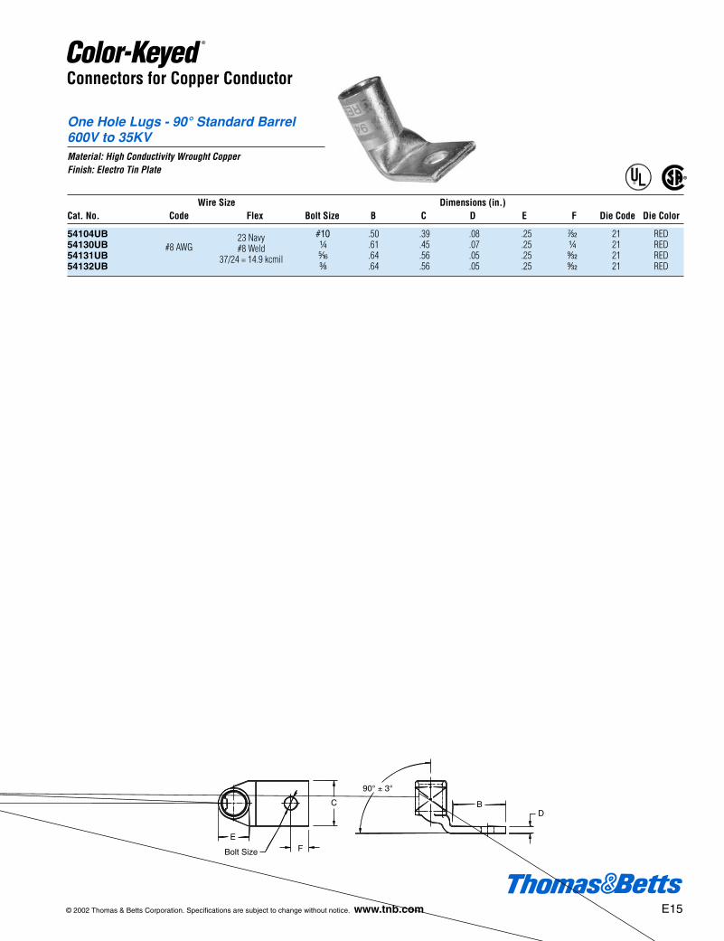
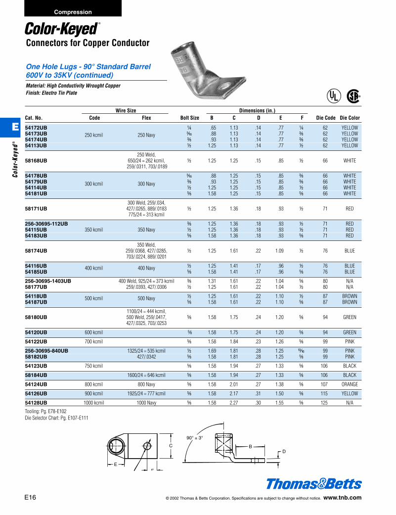
One Hole Lugs - 90° Standard Barrel600V to 35KVMaterial: High Conductivity Wrought CopperFinish: Electro Tin Plate
®
®
DB
90° ± 3°
Bolt Size
E
C
F
Connectors for Copper Conductor
Wire Size Dimensions (in.)Cat. No. Code Flex Bolt Size B C D E F Die Code Die Color
54104UB #10 .50 .39 .08 .25 r 21 RED54130UB
23 Navyb .61 .45 .07 .25 b 21 RED
54131UB#8 AWG #8 Weld
j .64 .56 .05 .25 s 21 RED54132UB
37/24 = 14.9 kcmilc .64 .56 .05 .25 s 21 RED
One Hole Lugs - 90° Standard Barrel600V to 35KV (continued)Material: High Conductivity Wrought CopperFinish: Electro Tin Plate
DB
90° ± 3°
E
C
F
®
®
Connectors for Copper Conductor
Wire Size Dimensions (in.)Cat. No. Code Flex Bolt Size B C D E F Die Code Die Color
54172UB b .65 1.13 .14 .77 b 62 YELLOW54173UB j .88 1.13 .14 .77 c 62 YELLOW54174UB
250 kcmil 250 Navyc .93 1.13 .14 .77 c 62 YELLOW
54113UB d 1.25 1.13 .14 .77 d 62 YELLOW
250 Weld, 58168UB 650/24 = 262 kcmil, d 1.25 1.25 .15 .85 d 66 WHITE
259/.0311, 703/.0189
54178UB j .88 1.25 .15 .85 c 66 WHITE54179UB c .93 1.25 .15 .85 c 66 WHITE54114UB
300 kcmil 300 Navyd 1.25 1.25 .15 .85 d 66 WHITE
54181UB e 1.58 1.25 .15 .85 e 66 WHITE
300 Weld, 259/.034, 58171UB 427/.0265, 889/.0183 d 1.25 1.36 .18 .93 d 71 RED
775/24 = 313 kcmil
256-30695-112UB c 1.25 1.36 .18 .93 d 71 RED54115UB 350 kcmil 350 Navy d 1.25 1.36 .18 .93 d 71 RED54183UB e 1.58 1.36 .18 .93 e 71 RED
350 Weld, 58174UB 259/.0368, 427/.0285, d 1.25 1.61 .22 1.09 d 76 BLUE
703/.0224, 889/.0201
54116UB d 1.25 1.41 .17 .96 d 76 BLUE54185UB
400 kcmil 400 Navye 1.58 1.41 .17 .96 e 76 BLUE
256-30695-1403UB 400 Weld, 925/24 = 373 kcmil c 1.31 1.61 .22 1.04 e 80 N/A58177UB 259/.0393, 427/.0306 d 1.25 1.61 .22 1.04 d 80 N/A
54118UB d 1.25 1.61 .22 1.10 d 87 BROWN54187UB
500 kcmil 500 Navye 1.58 1.61 .22 1.10 e 87 BROWN
1100/24 = 444 kcmil, 58180UB 500 Weld, 259/.0417, e 1.58 1.75 .24 1.20 e 94 GREEN
427/.0325, 703/.0253
54120UB 600 kcmil e 1.58 1.75 .24 1.20 e 94 GREEN
54122UB 700 kcmil e 1.58 1.84 .23 1.26 e 99 PINK
256-30695-840UB 1325/24 = 535 kcmil d 1.69 1.81 .28 1.25 m 99 PINK58182UB 427/.0342 e 1.58 1.81 .28 1.25 e 99 PINK
54123UB 750 kcmil e 1.58 1.94 .27 1.33 e 106 BLACK
58184UB 1600/24 = 646 kcmil e 1.58 1.94 .27 1.33 e 106 BLACK
54124UB 800 kcmil 800 Navy e 1.58 2.01 .27 1.38 e 107 ORANGE
54126UB 900 kcmil 1925/24 = 777 kcmil e 1.58 2.17 .31 1.50 e 115 YELLOW
54128UB 1000 kcmil 1000 Navy e 1.58 2.27 .30 1.55 e 125 N/A
Tooling: Pg. E78-E102Die Selector Chart: Pg. E107-E111
E16 © 2002 Thomas & Betts Corporation. Specifications are subject to change without notice. www.tnb.com
Compression
E
Colo
r-Ke
yed®
412031.E01 CK 3/5 3/13/03 8:22 PM Page 16
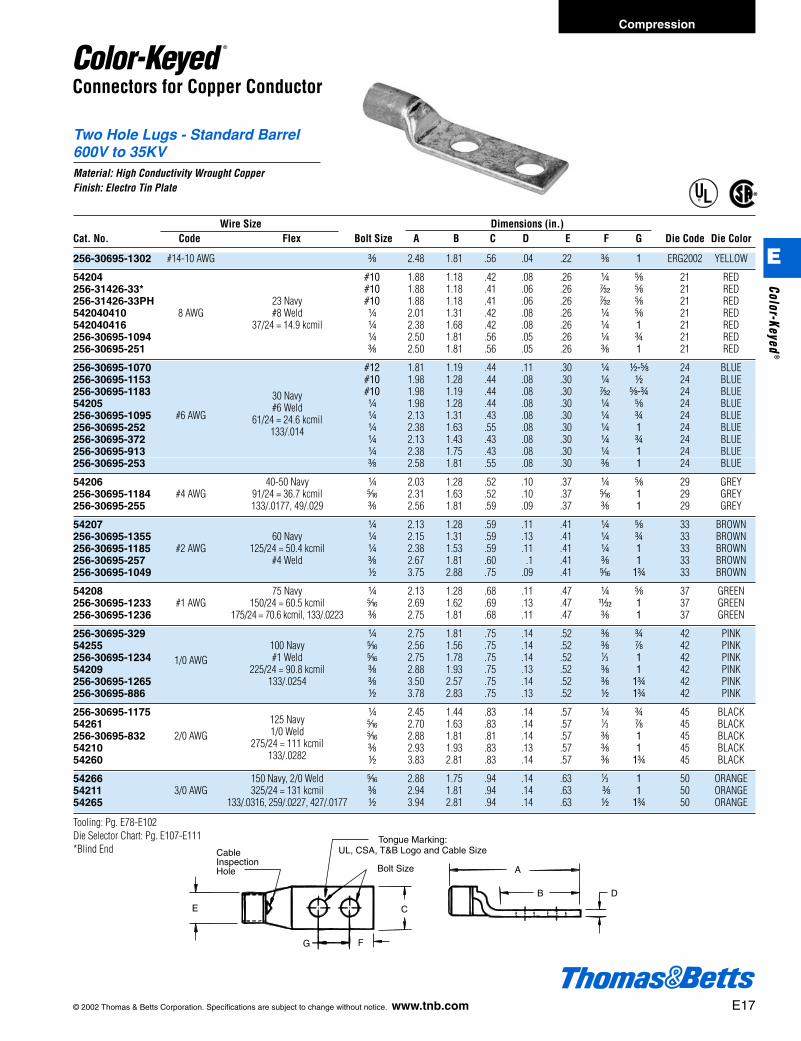
CableInspectionHole
G
Bolt Size
F
Tongue Marking:UL, CSA, T&B Logo and Cable Size
A
DB
CE
Connectors for Copper Conductor
Two Hole Lugs - Standard Barrel600V to 35KVMaterial: High Conductivity Wrought CopperFinish: Electro Tin Plate
®
®
Wire Size Dimensions (in.)Cat. No. Code Flex Bolt Size A B C D E F G Die Code Die Color
256-30695-1302 #14-10 AWG c 2.48 1.81 .56 .04 .22 c 1 ERG2002 YELLOW
54204 #10 1.88 1.18 .42 .08 .26 b e 21 RED256-31426-33* #10 1.88 1.18 .41 .06 .26 r e 21 RED256-31426-33PH 23 Navy #10 1.88 1.18 .41 .06 .26 r e 21 RED542040410 8 AWG #8 Weld b 2.01 1.31 .42 .08 .26 b e 21 RED542040416 37/24 = 14.9 kcmil b 2.38 1.68 .42 .08 .26 b 1 21 RED256-30695-1094 b 2.50 1.81 .56 .05 .26 b f 21 RED256-30695-251 c 2.50 1.81 .56 .05 .26 c 1 21 RED
256-30695-1070 #12 1.81 1.19 .44 .11 .30 b d-e 24 BLUE256-30695-1153 #10 1.98 1.28 .44 .08 .30 b d 24 BLUE256-30695-1183 #10 1.98 1.19 .44 .08 .30 r e-f 24 BLUE54205
30 Navyb 1.98 1.28 .44 .08 .30 b e 24 BLUE
256-30695-1095 #6 AWG#6 Weld
b 2.13 1.31 .43 .08 .30 b f 24 BLUE256-30695-252
61/24 = 24.6 kcmilb 2.38 1.63 .55 .08 .30 b 1 24 BLUE
256-30695-372133/.014
b 2.13 1.43 .43 .08 .30 b f 24 BLUE256-30695-913 b 2.38 1.75 .43 .08 .30 b 1 24 BLUE256-30695-253 c 2.58 1.81 .55 .08 .30 c 1 24 BLUE
54206 40-50 Navy b 2.03 1.28 .52 .10 .37 b e 29 GREY256-30695-1184 #4 AWG 91/24 = 36.7 kcmil j 2.31 1.63 .52 .10 .37 j 1 29 GREY256-30695-255 133/.0177, 49/.029 c 2.56 1.81 .59 .09 .37 c 1 29 GREY
54207 b 2.13 1.28 .59 .11 .41 b e 33 BROWN256-30695-1355 60 Navy b 2.15 1.31 .59 .13 .41 b f 33 BROWN256-30695-1185 #2 AWG 125/24 = 50.4 kcmil b 2.38 1.53 .59 .11 .41 b 1 33 BROWN256-30695-257 #4 Weld c 2.67 1.81 .60 .1 .41 c 1 33 BROWN256-30695-1049 d 3.75 2.88 .75 .09 .41 j 1f 33 BROWN
54208 75 Navy b 2.13 1.28 .68 .11 .47 b e 37 GREEN256-30695-1233 #1 AWG 150/24 = 60.5 kcmil j 2.69 1.62 .69 .13 .47 X 1 37 GREEN256-30695-1236 175/24 = 70.6 kcmil, 133/.0223 c 2.75 1.81 .68 .11 .47 c 1 37 GREEN
256-30695-329 b 2.75 1.81 .75 .14 .52 c f 42 PINK54255 100 Navy j 2.56 1.56 .75 .14 .52 c g 42 PINK256-30695-1234 #1 Weld j 2.75 1.78 .75 .14 .52 1⁄3 1 42 PINK54209
1/0 AWG225/24 = 90.8 kcmil c 2.88 1.93 .75 .13 .52 c 1 42 PINK
256-30695-1265 133/.0254 c 3.50 2.57 .75 .14 .52 c 1f 42 PINK256-30695-886 d 3.78 2.83 .75 .13 .52 d 1f 42 PINK
256-30695-1175125 Navy
b 2.45 1.44 .83 .14 .57 b f 45 BLACK54261
1/0 Weldj 2.70 1.63 .83 .14 .57 1⁄3 g 45 BLACK
256-30695-832 2/0 AWG275/24 = 111 kcmil
j 2.88 1.81 .81 .14 .57 c 1 45 BLACK54210
133/.0282c 2.93 1.93 .83 .13 .57 c 1 45 BLACK
54260 d 3.83 2.81 .83 .14 .57 c 1f 45 BLACK
54266 150 Navy, 2/0 Weld j 2.88 1.75 .94 .14 .63 1⁄3 1 50 ORANGE54211 3/0 AWG 325/24 = 131 kcmil c 2.94 1.81 .94 .14 .63 c 1 50 ORANGE54265 133/.0316, 259/.0227, 427/.0177 d 3.94 2.81 .94 .14 .63 d 1f 50 ORANGE
Tooling: Pg. E78-E102Die Selector Chart: Pg. E107-E111*Blind End
© 2002 Thomas & Betts Corporation. Specifications are subject to change without notice. www.tnb.com E17
Compression
E
Color-Keyed®
412031.E01 CK 3/5 3/13/03 8:22 PM Page 17

Connectors for Copper Conductor
Two Hole Lugs - Standard Barrel600V to 35KV (continued)Material: High Conductivity Wrought CopperFinish: Electro Tin Plate ®
®
CableInspectionHole
G
Bolt Size
F
Tongue Marking:UL, CSA, T&B Logo and Cable Size
A
DB
CE
Wire Size Dimensions (in.)Cat. No. Code Flex Bolt Size A B C D E F G Die Code Die Color
54212 c 3.18 1.93 1.03 .14 .70 c 1 54 PURPLE54270
200 Navyd 4.25 3.00 1.03 .14 .70 d 1f 54 PURPLE
256-30695-1247 4/0 AWG3/0 Weld
b 3.06 1.44 1.03 .16 .70 c e 54 PURPLE256-30695-331
450/24 = 182 kcmilb 3.06 1.81 1.03 .14 .70 c f 54 PURPLE
256-30695-1261703/.0154
j 3.18 1.93 1.03 .14 .70 c 1 54 PURPLE
54213250 kcmil 250 Navy
c 3.28 1.93 1.13 .14 .77 c 1 62 YELLOW54275 d 4.19 2.81 1.13 .18 .77 d 1f 62 YELLOW
256-30695-345 4/0 Weld c 3.25 1.69 1.25 .15 .79 c g 62 YELLOW256-30695-399 550/24 = 222 kcmil c 4.25 2.80 1.25 .15 .79 c 1 62 YELLOW256-30695-452 133/.0399 c 3.13 1.88 1.25 .16 .79 c g 62 YELLOW58265 259/.0286, 637/.018 d 3.94 2.81 .94 .14 .79 d 1f 62 YELLOW
54214300 kcmil 300 Navy
c 3.45 1.93 1.25 .15 .85 c 1 66 WHITE54280 d 4.45 3.00 1.25 .15 .85 d 1f 66 WHITE
256-30695-332 b 3.40 1.81 1.36 .18 .93 c f 71 RED256-30695-1240 j 4.18 2.63 1.36 .18 .93 c 1f 71 RED54215
350 kcmil 350 Navyc 3.51 1.93 1.36 .18 .93 c 1 71 RED
54282 d 4.60 3.00 1.36 .18 .93 d 1f 71 RED
54216400 kcmil
c 3.93 1.93 1.41 .17 .96 c 1 76 BLUE54283 c 3.88 1.93 1.41 .17 .96 c 1h 76 BLUE
256-30695-439 400 Weld c 4.35 2.25 1.61 .22 1.04 e 1 80 N/A58277 925/24 = 373 kcmil d 5.06 3.00 1.61 .22 1.04 d 1f 80 N/A256-30695-839 259/.0393, 427/.0306 c 4.09 2.06 1.61 .22 1.04 d 1 80 N/A
54218 c 3.96 1.93 1.61 .22 1.10 c 1 87 BROWN54286 500 kcmil 500 Navy d 5.07 3.00 1.61 .22 1.10 d 1f 87 BROWN256-30695-188 d 4.06 2.31 1.63 .22 1.10 d 1b 87 BROWN
54220 c 4.13 1.93 1.75 .24 1.20 c 1 94 GREEN54289
600 kcmil 1100/24 = 444 kcmild 5.23 3.00 1.75 .24 1.20 d 1f 94 GREEN
256-30695-1406 c 4.05 2.11 1.78 .24 1.25 d 1 99 PINK256-30695-842 c 4.30 2.06 1.80 .28 1.25 d 1 99 PINK256-30695-898 700 kcmil 1325/24 = 535 kcmil c 4.30 2.06 1.80 .28 1.25 d 1 99 PINK54291 d 5.18 3.00 1.84 .23 1.25 d 1f 99 PINK58281 d 5.23 3.00 1.80 .28 1.25 d 1f 99 PINK
256-30695-237 c 5.10 2.80 1.94 .27 1.33 c 1 106 BLACK54223
750 kcmild 5.32 3.00 1.94 .27 1.33 d 1f 106 BLACK
256-30695-1376 c 4.78 2.28 2.01 .27 1.38 k 1a 106 BLACK54224 800 kcmil d 5.50 3.00 2.01 .27 1.38 d 1f 106 BLACK
256-30695-694 c 4.65 2.06 2.18 .31 1.50 d 1 115 YELLOW54226 d 5.59 3.00 2.18 .31 1.50 d 1f 115 YELLOW256-30695-846
900 kcmil 1925/24 = 777 kcmilc 4.60 2.06 2.12 .31 1.50 d 1 115 YELLOW
256-30695-844 e 5.00 2.63 2.18 .31 1.50 l 1d 115 YELLOW
54228 1000 kcmil 1000 Navy d 5.45 3.00 2.27 .30 1.55 d 1f 125 N/A
Tooling: Pg. E78-E102Die Selector Chart: Pg. E107-E111
E18 © 2002 Thomas & Betts Corporation. Specifications are subject to change without notice. www.tnb.com
Compression
E
Colo
r-Ke
yed®
412031.E01 CK 3/5 3/13/03 8:22 PM Page 18
®
®
Connectors for Copper Conductor
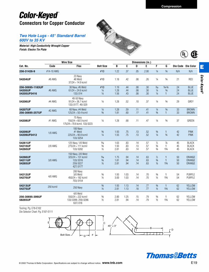
Two Hole Lugs - 45° Standard Barrel600V to 35 KVMaterial: High Conductivity Wrought CopperFinish: Electro Tin Plate
D
45° ± 3°CE
FGBolt Size
B
Wire Size Dimensions (in.)Cat. No. Code Flex Bolt Size B C D E F G Die Code Die Color
256-31426-9 #14-10 AWG #10 1.22 .37 .05 .2.00 b e N/A N/A
23 Navy54204UF #8 AWG #8 Weld #10 1.18 .42 .08 .26 b e 21 RED
37/24 = 14.9 kcmil
256-30695-1183UF 30 Navy, #6 Weld #10 1.19 .44 .08 .30 r e-f 24 BLUE54205UF #6 AWG 61/24 = 24.6 kcmil b 1.28 .44 .08 .30 b e 24 BLUE54205UF0416 133/.014 b 1.56 .43 .08 .30 b 1 24 BLUE
40-50 Navy54206UF #4 AWG 91/24 = 36.7 kcmil b 1.28 .52 .10 .37 b e 29 GREY
133/.0177, 49/.029
54207UF 60 Navy, #4 Weld b 1.28 .59 .11 .41 b e 33 BROWN256-30695-257UF
#2 AWG 125/24 = 50.4 kcmil c 1.81 .60 .1? .41 c 1 33 BROWN
75 Navy54208UF #1 AWG 150/24 = 60.5 kcmil b 1.28 .68 .11 .47 b e 37 GREEN
175/24 = 70.6 kcmil, 133/.0223
100 Navy54209UF #1 Weld c 1.93 .75 .13 .52 c 1 42 PINK54209UF0412
1/0 AWG225/24 = 90.8 kcmil b 1.55 .75 .13 .52 b f 42 PINK
133/.0254
54261UF 125 Navy, 1/0 Weld j 1.63 .83 .14 .57 1⁄3 g 45 BLACK54210UF 2/0 AWG 275/24 = 111 kcmil c 1.93 .83 .13 .57 c 1 45 BLACK54260UF 133/.0282 d 2.81 .83 .14 .57 c 1f 45 BLACK
150 Navy, 2/0 Weld54266UF 325/24 = 131 kcmil j 1.75 .94 .14 .63 1⁄3 1 50 ORANGE54211UF 3/0 AWG 133/.0316 c 1.81 .94 .14 .63 c 1 50 ORANGE54265UF 259/.0227 d 2.81 .94 .14 .63 d 1f 50 ORANGE
427/.0177
200 Navy54212UF
4/0 AWG3/0 Weld c 1.93 1.03 .14 .70 c 1 54 PURPLE
54270UF 450/24 = 182 kcmil d 3.00 1.03 .14 .70 d 1f 54 PURPLE703/.0154
54213UF c 1.93 1.13 .14 .77 c 1 62 YELLOW54275UF
250 kcmil 250 Navy d 2.81 1.13 .18 .77 d 1f 62 YELLOW
4/0 Weld256-30695-399UF 550/24 = 222 kcmil c 2.80 1.25 .15 .79 c 1 62 YELLOW58265UF 133/.0399, 259/.0286 d 2.81 .94 .14 .79 d 1f 62 YELLOW
637/.018
Tooling: Pg. E78-E102Die Selector Chart: Pg. E107-E111
© 2002 Thomas & Betts Corporation. Specifications are subject to change without notice. www.tnb.com E19
Compression
E
Color-Keyed®
412031.E01 CK 3/5 3/13/03 8:22 PM Page 19
E20 © 2002 Thomas & Betts Corporation. Specifications are subject to change without notice. www.tnb.com
Compression
E
Colo
r-Ke
yed®
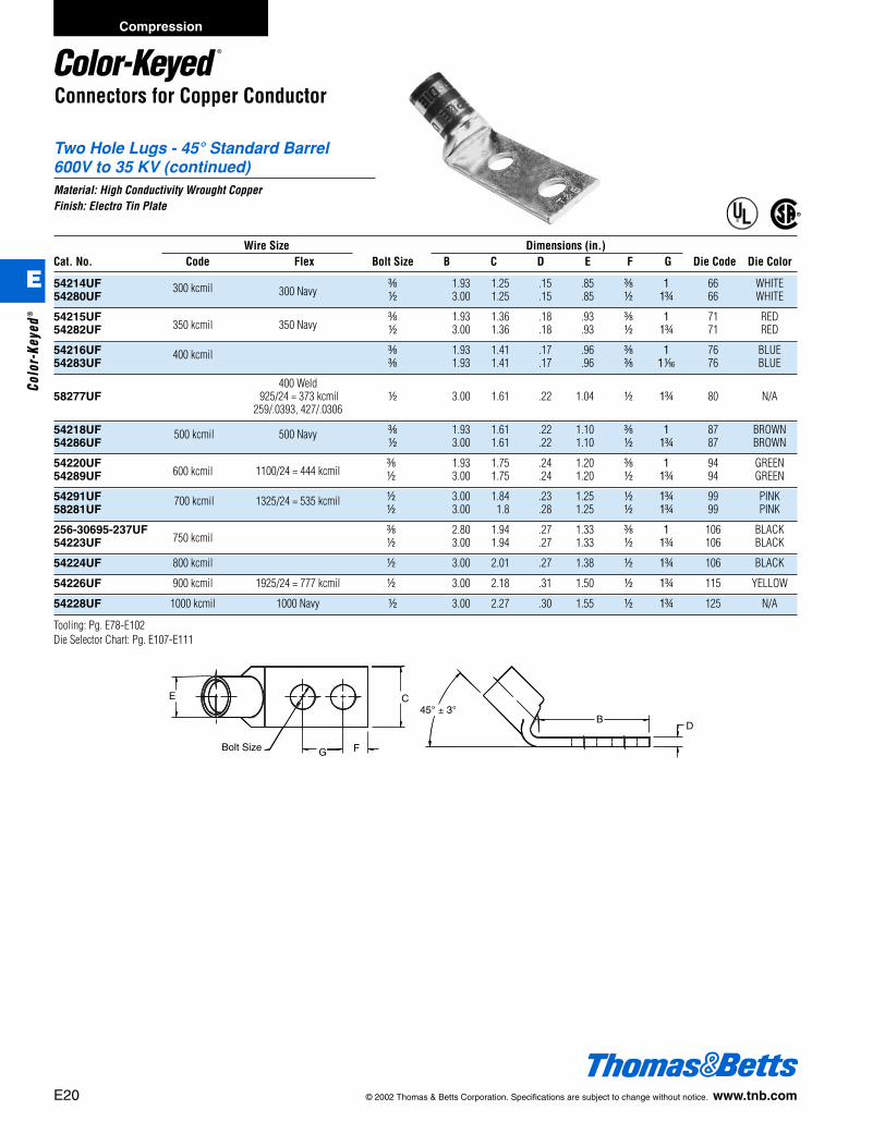
Connectors for Copper Conductor
Two Hole Lugs - 45° Standard Barrel600V to 35 KV (continued)Material: High Conductivity Wrought CopperFinish: Electro Tin Plate
D
45° ± 3°CE
FGBolt Size
B
®
®
Wire Size Dimensions (in.)Cat. No. Code Flex Bolt Size B C D E F G Die Code Die Color
54214UF c 1.93 1.25 .15 .85 c 1 66 WHITE54280UF
300 kcmil 300 Navy d 3.00 1.25 .15 .85 d 1f 66 WHITE
54215UF350 kcmil 350 Navy
c 1.93 1.36 .18 .93 c 1 71 RED54282UF d 3.00 1.36 .18 .93 d 1f 71 RED
54216UF c 1.93 1.41 .17 .96 c 1 76 BLUE54283UF
400 kcmil c 1.93 1.41 .17 .96 c 1h 76 BLUE
400 Weld58277UF 925/24 = 373 kcmil d 3.00 1.61 .22 1.04 d 1f 80 N/A
259/.0393, 427/.0306
54218UF c 1.93 1.61 .22 1.10 c 1 87 BROWN54286UF
500 kcmil 500 Navyd 3.00 1.61 .22 1.10 d 1f 87 BROWN
54220UF600 kcmil
c 1.93 1.75 .24 1.20 c 1 94 GREEN54289UF 1100/24 = 444 kcmil d 3.00 1.75 .24 1.20 d 1f 94 GREEN
54291UF d 3.00 1.84 .23 1.25 d 1f 99 PINK58281UF
700 kcmil 1325/24 = 535 kcmild 3.00 1.8 .28 1.25 d 1f 99 PINK
256-30695-237UF750 kcmil
c 2.80 1.94 .27 1.33 c 1 106 BLACK54223UF d 3.00 1.94 .27 1.33 d 1f 106 BLACK
54224UF 800 kcmil d 3.00 2.01 .27 1.38 d 1f 106 BLACK
54226UF 900 kcmil 1925/24 = 777 kcmil d 3.00 2.18 .31 1.50 d 1f 115 YELLOW
54228UF 1000 kcmil 1000 Navy d 3.00 2.27 .30 1.55 d 1f 125 N/A
Tooling: Pg. E78-E102Die Selector Chart: Pg. E107-E111
412031.E01 CK 3/5 3/13/03 8:22 PM Page 20
© 2002 Thomas & Betts Corporation. Specifications are subject to change without notice. www.tnb.com E21
Compression
E
Color-Keyed®
Connectors for Copper Conductor
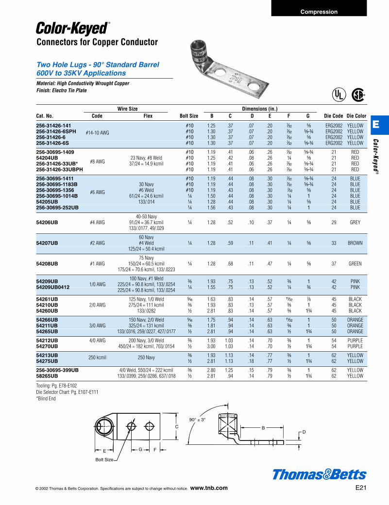
Two Hole Lugs - 90° Standard Barrel600V to 35KV ApplicationsMaterial: High Conductivity Wrought CopperFinish: Electro Tin Plate
C
E
Bolt Size
G F
DB
90° ± 3°
®
®
Wire Size Dimensions (in.)Cat. No. Code Flex Bolt Size B C D E F G Die Code Die Color
256-31426-141 #10 1.25 .37 .07 .20 r e ERG2002 YELLOW256-31426-6SPH #10 1.30 .37 .07 .20 r e-f ERG2002 YELLOW256-31426-6
#14-10 AWG#10 1.30 .37 .07 .20 r e ERG2002 YELLOW
256-31426-6S #10 1.30 .37 .07 .20 r e-f ERG2002 YELLOW
256-30695-1409 #10 1.19 .41 .06 .26 r e-f 21 RED54204UB
#8 AWG23 Navy, #8 Weld #10 1.25 .42 .08 .26 b e 21 RED
256-31426-33UB* 37/24 = 14.9 kcmil #10 1.19 .41 .06 .26 r e-f 21 RED256-31426-33UBPH #10 1.19 .41 .06 .26 r e-f 21 RED
256-30695-1411 #10 1.19 .44 .08 .30 r e-f 24 BLUE256-30695-1183B 30 Navy #10 1.19 .44 .08 .30 r e-f 24 BLUE256-30695-1356 #6 Weld #10 1.19 .43 .08 .30 r e 24 BLUE256-30695-1014B
#6 AWG61/24 = 24.6 kcmil b 1.50 .44 .08 .30 b 1 24 BLUE
54205UB 133/.014 b 1.28 .44 .08 .30 b e 24 BLUE256-30695-252UB b 1.56 .43 .08 .30 b 1 24 BLUE
40-50 Navy54206UB #4 AWG 91/24 = 36.7 kcmil b 1.28 .52 .10 .37 b e 29 GREY
133/.0177, 49/.029
60 Navy54207UB #2 AWG #4 Weld b 1.28 .59 .11 .41 b e 33 BROWN
125/24 = 50.4 kcmil
75 Navy54208UB #1 AWG 150/24 = 60.5 kcmil b 1.28 .68 .11 .47 b e 37 GREEN
175/24 = 70.6 kcmil, 133/.0223
100 Navy, #1 Weld54209UB 1/0 AWG 225/24 = 90.8 kcmil, 133/.0254 c 1.93 .75 .13 .52 c 1 42 PINK54209UB0412 225/24 = 90.8 kcmil, 133/.0254 b 1.55 .75 .13 .52 b f 42 PINK
54261UB 125 Navy, 1/0 Weld j 1.63 .83 .14 .57 X g 45 BLACK54210UB 2/0 AWG 275/24 = 111 kcmil c 1.93 .83 .13 .57 c 1 45 BLACK54260UB 133/.0282 d 2.81 .83 .14 .57 c 1f 45 BLACK
54266UB 150 Navy, 2/0 Weld j 1.75 .94 .14 .63 X 1 50 ORANGE54211UB 3/0 AWG 325/24 = 131 kcmil c 1.81 .94 .14 .63 c 1 50 ORANGE54265UB 133/.0316, 259/.0227, 427/.0177 d 2.81 .94 .14 .63 d 1f 50 ORANGE
54212UB 4/0 AWG 200 Navy, 3/0 Weld c 1.93 1.03 .14 .70 c 1 54 PURPLE54270UB 450/24 = 182 kcmil, 703/.0154 d 3.00 1.03 .14 .70 d 1f 54 PURPLE
54213UB c 1.93 1.13 .14 .77 c 1 62 YELLOW54275UB
250 kcmil 250 Navyd 2.81 1.13 .18 .77 d 1f 62 YELLOW
256-30695-399UB 4/0 Weld, 550/24 = 222 kcmil c 2.80 1.25 .15 .79 c 1 62 YELLOW58265UB 133/.0399, 259/.0286, 637/.018 d 2.81 .94 .14 .79 d 1f 62 YELLOW
Tooling: Pg. E78-E102Die Selector Chart: Pg. E107-E111*Blind End
412031.E01 CK 3/5 3/13/03 8:22 PM Page 21
E22 © 2002 Thomas & Betts Corporation. Specifications are subject to change without notice. www.tnb.com
Connectors for Copper Conductor
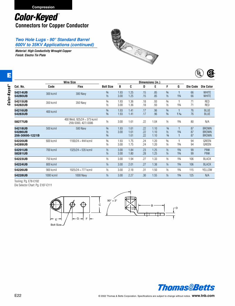
Two Hole Lugs - 90° Standard Barrel600V to 35KV Applications (continued)Material: High Conductivity Wrought CopperFinish: Electro Tin Plate
C
E
Bolt Size
G F
DB
90° ± 3°
®
®
Wire Size Dimensions (in.)Cat. No. Code Flex Bolt Size B C D E F G Die Code Die Color
54214UB c 1.93 1.25 .15 .85 c 1 66 WHITE54280UB
300 kcmil 300 Navyd 3.00 1.25 .15 .85 d 1f 66 WHITE
54215UB c 1.93 1.36 .18 .93 c 1 71 RED54282UB
350 kcmil 350 Navyd 3.00 1.36 .18 .93 d 1f 71 RED
54216UB c 1.93 1.41 .17 .96 c 1 76 BLUE54283UB
400 kcmilc 1.93 1.41 .17 .96 c 1h 76 BLUE
58277UB400 Weld, 925/24 = 373 kcmil
d 3.00 1.61 .22 1.04 d 1f 80 N/A259/.0393, 427/.0306
54218UB 500 kcmil 500 Navy c 1.93 1.61 .22 1.10 c 1 87 BROWN54286UB d 3.00 1.61 .22 1.10 d 1f 87 BROWN256-30695-1221B c 1.61 .22 1.10 c 1 87 BROWN
54220UB 600 kcmil 1100/24 = 444 kcmil c 1.93 1.75 .24 1.20 c 1 94 GREEN54289UB d 3.00 1.75 .24 1.20 d 1f 94 GREEN
54291UB 700 kcmil 1325/24 = 535 kcmil d 3.00 1.84 .23 1.25 d 1f 99 PINK58281UB d 3.00 1.80 .28 1.25 d 1f 99 PINK
54223UB 750 kcmil d 3.00 1.94 .27 1.33 d 1f 106 BLACK
54224UB 800 kcmil d 3.00 2.01 .27 1.38 d 1f 106 BLACK
54226UB 900 kcmil 1925/24 = 777 kcmil d 3.00 2.18 .31 1.50 d 1f 115 YELLOW
54228UB 1000 kcmil 1000 Navy d 3.00 2.27 .30 1.55 d 1f 125 N/A
Tooling: Pg. E78-E102Die Selector Chart: Pg. E107-E111
Compression
E
Colo
r-Ke
yed®
412031.E01 CK 3/5 3/13/03 8:22 PM Page 22

© 2002 Thomas & Betts Corporation. Specifications are subject to change without notice. www.tnb.com E23
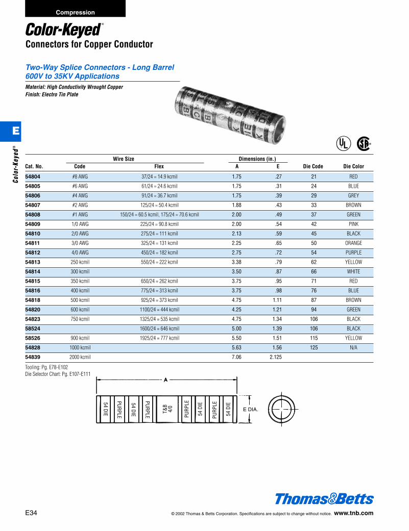
Two-Way Splice Connectors - Standard Barrel600V to 35KVMaterial: High Conductivity Wrought CopperFinish: Electro Tin Plate
Two-way connectors provide high pullout values, are easy to insulate, andprovide a low resistance connection of high quality and low installed cost.
®
®
Connectors for Copper Conductor
A
E
Wire Size Dimensions (in.)Cat. No. Code Flex A E Die Code Die Color
54504 #8 AWG 37/24 = 14.9 kcmil, #8 Weld 1.00 .27 21 RED
54505 #6 AWG 61/24 = 24.6 kcmil, #6 Weld, 133/.014 1.00 .30 24 BLUE
54506 #4 AWG 91/24 = 36.7 kcmil, 133/.0177, 49/.029 1.00 .37 29 GREY
54507 #2 AWG 125/24 = 50.4 kcmil, #4 Weld 1.25 .41 33 BROWN
54508 #1 AWG 150/24 = 60.5 kcmil, 175/24 = 70.6 kcmil, #2 Weld, 133/.0223 1.50 .47 37 GREEN
54509 1/0 AWG 225/24 = 90.8 kcmil, #1 Weld, 133/.0254 1.63 .52 42 PINK
54510 2/0 AWG 275/24 = 111 kcmil, 1/0 Weld, 427/.0155, 133/.0282 1.75 .57 45 BLACK
54511 3/0 AWG 325/24 = 131kcmil, 2/0 Weld, 133/.0316, 259/.0227, 427/.0177 1.75 .63 50 ORANGE
53962 375/24 = 179 kcmil, 133/.0355, 259/.0255, 427/.0199 1.81 .70 50 ORANGE
54512 4/0 AWG 450/24 = 182 kcmil, 3/0 Weld, 703/.0154 1.88 .70 54 PURPLE
54513 250 kcmil 2.25 .77 62 YELLOW
53964 550/24 = 222 kcmil, 4/0 Weld, 133/.0399, 259/.0286, 637/.0183 2.13 .79 62 YELLOW
54514 300 kcmil 2.13 .83 66 WHITE
54515 350 kcmil 2.25 .90 71 RED
54516 400 kcmil 2.75 .93 76 BLUE
53968 1100/24 = 444 kcmil, 500 Weld, 259/.0417, 427/.0325, 703/.0253 3.00 1.13 87 BROWN
54518 500 kcmil 2.75 1.11 87 BROWN
54520 600 kcmil 3.00 1.18 94 GREEN
54522-TB 700 kcmil 3.25 1.23 99 PINK
53969 1325/24 = 535 kcmil, 427/.0342 3.00 1.24 99 PINK
54523-TB 750 kcmil 3.00 1.30 106 BLACK
54528 1000 kcmil 3.63 1.50 125 N/A
54530 1250 kcmil 4.13 1.67 140 N/A
Tooling: Pg. E78-E102Die Selector Chart: Pg. E107-E111
Compression
E
Color-Keyed®
412031.E01 CK 3/5 3/13/03 8:22 PM Page 23

E24 © 2002 Thomas & Betts Corporation. Specifications are subject to change without notice. www.tnb.com
Compression
E
Colo
r-Ke
yed®
Connectors for Copper Conductor
Narrow Tongue Lugs - Standard Barrel600V ApplicationsMaterial: High Conductivity Wrought CopperFinish: Electro Tin Plate
®
®
C
F
D
A
B
C
F
E
D
A
G
Figure 1
Figure 2
Wire Size Bolt Dimensions (in.)Cat. No. Code Flex Hole Fig. # A B C D E F G Die Code Die Color
55112 #4 AWG 91/24 = 36.7 kcmil b 1 1.38 .56 .50 .09 .37 b 29 GREY
55116 #2 AWG 125/24 = 50.4 kcmil b 1 1.50 .56 .50 .09 .41 b 33 BROWN
150/24 = 60.5 kcmil, 55122 #1 AWG 175/24 = 70.6 kcmil, #2 Weld b 1 1.88 .94 .55 .11 .47 b 37 GREEN
55130 1/0 AWG 225/24 = 90.8 kcmil b 1 1.88 .94 .64 .13 .52 b 42 PIN
55136 2/0 AWG 275/24 = 111 kcmil, 1/0 Weld b 1 2.25 1.14 .64 .13 .57 b 45 BLACK
55142 3/0 AWG 325/24 = 131 kcmil, 2/0 Weld b 1 2.37 1.14 .78 .13 .63 b 50 ORANGE
55148 4/0 AWG 450/24 = 182 kcmil b 1 2.45 1.14 .78 .14 .70 b 54 PURPLE
55156 250 kcmil 550/24 = 222 kcmil, 4/0 Weld b 1 2.85 1.14 .98 .14 .77 b 62 YELLOW
55162 300 kcmil b 1 2.71 1.20 .98 .19 .85 j 66 WHITE
55165 350 kcmil d 1 3.13 1.39 1.09 .18 .93 d 71 RED256-30695-1340 350 kcmil c 1 3.10 1.27 .98 .18 .93 d 71 RED
55171 500 kcmil 925/24 = 373 kcmil d 1 3.58 1.39 1.20 .22 1.10 d 87 BROWN
54879NT 750 kcmil c 2 5.00 2.02 1.66 .27 1.33 d 1 106 BLACK256-30695-1266 750 kcmil 1325/24 = 535 kcmil d 1 3.71 1.58 1.49 .27 1.33 f 106 BLACK55178 750 kcmil e 1 3.71 1.70 1.49 .27 1.33 f 106 BLACK
58825NT 900 kcmil c 2 5.00 2.13 1.66 .31 1.50 d 1 115 YELLOW58825NT0828 900 kcmil
1925/24 = 777 kcmild 2 5.75 2.88 1.66 .31 1.50 d 1f 115 YELLOW
Tooling: Pg. E78-E102Die Selector Chart: Pg. E107-E111
412031.E01 CK 3/5 3/13/03 8:22 PM Page 24
© 2002 Thomas & Betts Corporation. Specifications are subject to change without notice. www.tnb.com E25
Compression
E
Color-Keyed®
Connectors for Copper Conductor
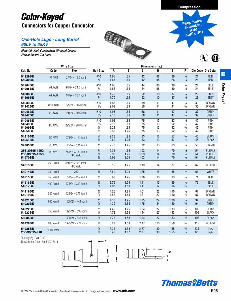
One-Hole Lugs - Long Barrel600V to 35KVMaterial: High Conductivity Wrought CopperFinish: Electro Tin Plate
E
F
C
A
BD
®
®
Peep holes
available.
Addsuffix -PH
Wire Size Dimensions (in.)Cat. No. Code Flex Bolt Size A B C D E F Die Code Die Color
54929BE #10 1.65 .65 .42 .08 .26 b 21 RED54930BE
#8 AWG 37/24 = 14.9 kcmilb 1.65 .65 .42 .08 .26 b 21 RED
54904BE#6 AWG 61/24 = 24.6 kcmil
#10 1.65 .65 .44 .08 .30 b 24 BLUE54905BE b 1.65 .65 .44 .08 .30 b 24 BLUE
54908BE #10 1.70 .65 .52 .10 .37 b 29 GREY54906BE
#4 AWG 91/24 = 36.7 kcmilb 1.70 .65 .52 .10 .37 b 29 GREY
54933BE#2-3 AWG 125/24 = 50.4 kcmil
#10 1.88 .65 .59 .11 .41 b 33 BROWN54942BE j 2.03 .88 .59 .11 .41 c 33 BROWN
54945BE #10 1.95 .65 .68 .11 .47 b 37 GREEN54947BE
#1 AWG 150/24 = 60.5 kcmilj 2.18 .88 .68 .11 .47 c 37 GREEN
54946BE #10 1.95 .65 .75 .13 .52 b 42 PINK54949BE j 2.18 .88 .75 .13 .52 c 42 PINK54909BE
1/0 AWG 225/24 = 90.8 kcmilc 2.23 .93 .75 .13 .52 c 42 PINK
54950BE d 2.55 1.25 .75 .13 .52 d 42 PINK
54910BE c 2.28 .93 .83 .13 .57 c 45 BLACK54951BE
2/0 AWG 275/24 = 111 kcmild 2.60 1.25 .83 .13 .57 d 45 BLACK
54965BE 3/0 AWG 325/24 = 131 kcmil d 2.70 1.25 .92 .13 .63 d 50 ORANGE
256-30695-1252 b 2.35 .65 1.03 .14 .70 b 54 PURPLE256-30695-1253
4/0 AWG 450/24 = 182 kcmilc 2.95 1.25 1.03 .14 .70 c 54 PURPLE
54970BE3/0 Weld
d 2.95 1.25 1.03 .14 .70 d 54 PURPLE
54913BE250 kcmil 550/24 = 222 kcmil,
d 3.15 1.25 1.13 .14 .77 d 62 YELLOW4/0 Weld
54914BE 300 kcmil 250 d 3.50 1.25 1.25 .15 .85 d 66 WHITE
54915BE 350 kcmil 650/24 = 262 kcmil d 3.68 1.25 1.36 .18 .93 d 71 RED
54916BE d 3.75 1.25 1.41 .17 .96 d 76 BLUE54917BE
400 kcmil 775/24 = 313 kcmile 4.03 1.58 1.41 .17 .96 e 76 BLUE
54918BE500 kcmil 925/24 = 373 kcmil
d 4.25 1.25 1.61 .22 1.10 d 87 BROWN54919BE e 4.57 1.58 1.61 .22 1.10 e 87 BROWN
54921BE d 4.10 1.25 1.75 .24 1.20 d 94 GREEN54920BE
600 kcmil 1100/24 = 444 kcmile 4.39 1.58 1.75 .24 1.20 e 94 GREEN
54922BE750 kcmil 1325/24 = 535 kcmil
d 4.40 1.25 1.94 .27 1.33 d 106 BLACK54923BE e 4.72 1.58 1.94 .27 1.33 e 106 BLACK
58984BE 1600/24 = 646 kcmil e 4.73 1.58 1.94 .27 1.33 e 106 BLACK
58926BE 900 kcmil 1925/24 = 777 kcmil e 5.23 1.58 2.17 .310 1.50 e 115 YELLOW
54928BE e 5.24 1.58 2.27 .30 1.55 e 125 N/A256-30695-918
1000 kcmilg 5.42 1.82 2.37 .30 1.55 g 125 N/A
Tooling: Pg. E78-E102Die Selector Chart: Pg. E107-E111
412031.E01 CK 3/5 3/13/03 8:22 PM Page 25

E26 © 2002 Thomas & Betts Corporation. Specifications are subject to change without notice. www.tnb.com
One Hole Lugs - 45° Long Barrel600V to 35KV Material: High Conductivity Wrought CopperFinish: Electro Tin Plate
®
®
45° ± 3°DB
Bolt size
E
F
C
Connectors for Copper Conductor
Peep holes
available.
Addsuffix -PH
Wire Size Dimensions (in.)Cat. No. Code Flex Bolt Size B C D E F Die Code Die Color
54929BEUF #10 .65 .42 .08 .26 b 21 RED54930BEUF
#8 AWG 37/24 = 14.9 kcmilb .65 .42 .08 .26 b 21 RED
54904BEUF#6 AWG 61/24 = 24.6 kcmil
#10 .65 .44 .08 .30 b 24 BLUE54905BEUF b .65 .44 .08 .30 b 24 BLUE
54908BEUF #10 .65 .52 .10 .37 b 29 GREY54906BEUF
#4 AWG 91/24 = 36.7 kcmilb .65 .52 .10 .37 b 29 GREY
54933BEUF#2-3 AWG 125/24 = 50.4 kcmil
#10 .65 .59 .11 .41 b 33 BROWN54942BEUF j .88 .59 .11 .41 c 33 BROWN
54945BEUF #10 .65 .68 .11 .47 b 37 GREEN54947BEUF
#1 AWG 150/24 = 60.5 kcmilj .88 .68 .11 .47 c 37 GREEN
54946BEUF #10 .65 .75 .13 .52 b 42 PINK54949BEUF j .88 .75 .13 .52 c 42 PINK54909BEUF
1/0 AWG 225/24 = 90.8 kcmilc .93 .75 .13 .52 c 42 PINK
54950BEUF d 1.25 .75 .13 .52 d 42 PINK
54910BEUF c .93 .83 .13 .57 3/8 45 BLACK54951BEUF
2/0 AWG 275/24 = 111 kcmild 1.25 .83 .13 .57 d 45 BLACK
54965BEUF 3/0 AWG 325/24 = 131 kcmil d 1.25 .92 .13 .63 d 50 ORANGE
54970BEUF04 b 1.00 1.03 .14 .70 b 54 PURPLE54970BEUF06
4/0 AWG 450/24 = 182 kcmilc 1.13 1.03 .14 .70 c 54 PURPLE
54970BEUF3/0 Weld
d 1.25 1.03 .14 .70 d 54 PURPLE
54913BEUF250 kcmil 550/24 = 222 kcmil,
d 1.25 1.13 .14 .77 d 62 YELLOW4/0 Weld
54914BEUF 300 kcmil 250 d 1.25 1.25 .15 .85 d 66 WHITE
54915BEUF 350 kcmil 650/24 = 262 kcmil d 1.25 1.36 .18 .93 d 71 RED
54916BEUF d 1.25 1.41 .17 .96 d 76 BLUE54917BEUF
400 kcmil 775/24 = 313 kcmile 1.58 1.41 .17 .96 e 76 BLUE
54918BEUF500 kcmil 925/24 = 373 kcmil
d 1.25 1.61 .22 1.10 d 87 BROWN54919BEUF e 1.58 1.61 .22 1.10 e 87 BROWN
54921BEUF d 1.25 1.75 .24 1.20 d 94 GREEN54920BEUF
600 kcmil 1100/24 = 444 kcmile 1.58 1.75 .24 1.20 e 94 GREEN
54922BEUF750 kcmil 1325/24 = 535 kcmil
d 1.25 1.94 .27 1.33 d 106 BLACK54923BEUF e 1.58 1.94 .27 1.33 e 106 BLACK
58984BEUF 1600/24 = 646 kcmil e 1.58 1.94 .27 1.33 e 106 BLACK
58926BEUF 900 kcmil 1925/24 = 777 kcmil e 1.58 2.17 .31 1.50 e 115 YELLOW
54928BEUF e 1.58 2.27 .30 1.55 e 125 N/A54928BEUF12
1000 kcmilg 1.83 2.37 .30 1.55 g 125 N/A
Tooling: Pg. E78-E102Die Selector Chart: Pg. E107-E111
Compression
E
Colo
r-Ke
yed®
412031.E01 CK 3/5 3/13/03 8:22 PM Page 26

© 2002 Thomas & Betts Corporation. Specifications are subject to change without notice. www.tnb.com E27
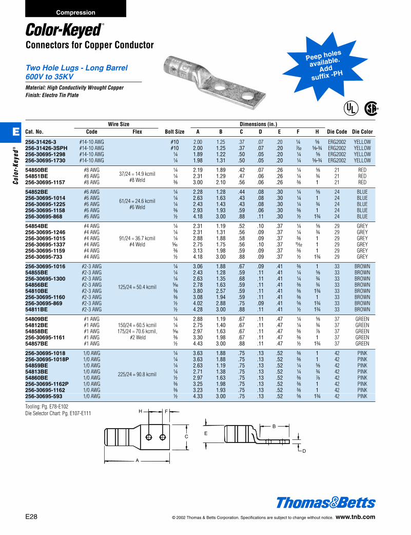
Connectors for Copper Conductor
Two Hole Lugs - Long Barrel600V to 35KVMaterial: High Conductivity Wrought CopperFinish: Electro Tin Plate
A
EC
D
B
H F
®
®
Peep holes
available.
Addsuffix -PH
Wire Size Dimensions (in.)Cat. No. Code Flex Bolt Size A B C D E F H Die Code Die Color
256-31426-3 #14-10 AWG #10 2.00 1.25 .37 .07 .20 b e ERG2002 YELLOW256-31426-3SPH #14-10 AWG #10 2.00 1.25 .37 .07 .20 r e-f ERG2002 YELLOW256-30695-1298 #14-10 AWG b 1.89 1.22 .50 .05 .20 b e ERG2002 YELLOW256-30695-1730 #14-10 AWG b 1.98 1.31 .50 .05 .20 b e-f ERG2002 YELLOW
54850BE #8 AWG37/24 = 14.9 kcmil
b 2.19 1.89 .42 .07 .26 b e 21 RED54851BE #8 AWG
#8 Weldb 2.31 1.29 .47 .06 .26 b f 21 RED
256-30695-1157 #8 AWG c 3.00 2.10 .56 .06 .26 c 1 21 RED
54852BE #6 AWG b 2.28 1.28 .44 .08 .30 b e 24 BLUE256-30695-1014 #6 AWG b 2.63 1.63 .43 .08 .30 b 1 24 BLUE256-30695-1225 #6 AWG 61/24 = 24.6 kcmil b 2.43 1.43 .43 .08 .30 b f 24 BLUE256-30695-1158 #6 AWG #6 Weld c 2.93 1.93 .59 .06 .30 c 1 24 BLUE256-30695-868 #6 AWG d 4.18 3.00 .88 .11 .30 d 1f 24 BLUE
54854BE #4 AWG b 2.31 1.19 .52 .10 .37 b e 29 GREY256-30695-1246 #4 AWG b 2.31 1.31 .56 .09 .37 b f 29 GREY256-30695-1015 #4 AWG 91/24 = 36.7 kcmil b 2.88 1.88 .58 .09 .37 c 1 29 GREY256-30695-1337 #4 AWG #4 Weld j 2.75 1.75 .56 .10 .37 X 1 29 GREY256-30695-1159 #4 AWG c 3.13 1.98 .59 .09 .37 c 1 29 GREY256-30695-733 #4 AWG d 4.18 3.00 .88 .09 .37 d 1f 29 GREY
256-30695-1016 #2-3 AWG b 3.06 1.88 .67 .09 .41 c 1 33 BROWN54855BE #2-3 AWG b 2.43 1.28 .59 .11 .41 b e 33 BROWN256-30695-1300 #2-3 AWG b 2.63 1.35 .68 .11 .41 b f 33 BROWN54856BE #2-3 AWG j 2.78 1.63 .59 .11 .41 c f 33 BROWN54810BE #2-3 AWG
125/24 = 50.4 kcmilc 3.80 2.57 .59 .11 .41 c 1f 33 BROWN
256-30695-1160 #2-3 AWG c 3.08 1.94 .59 .11 .41 c 1 33 BROWN256-30695-869 #2-3 AWG d 4.02 2.88 .75 .09 .41 e 1f 33 BROWN54811BE #2-3 AWG d 4.28 3.00 .88 .11 .41 d 1f 33 BROWN
54809BE #1 AWG b 2.88 1.19 .67 .11 .47 b e 37 GREEN54812BE #1 AWG 150/24 = 60.5 kcmil b 2.75 1.40 .67 .11 .47 b f 37 GREEN54858BE #1 AWG 175/24 = 70.6 kcmil, j 2.97 1.63 .67 .11 .47 c g 37 GREEN256-30695-1161 #1 AWG #2 Weld c 3.30 1.98 .67 .11 .47 c 1 37 GREEN54857BE #1 AWG d 4.43 3.00 .88 .11 .47 d 1f 37 GREEN
256-30695-1018 1/0 AWG b 3.63 1.88 .75 .13 .52 c 1 42 PINK256-30695-1018P 1/0 AWG b 3.63 1.88 .75 .13 .52 c 1 42 PINK54859BE 1/0 AWG b 2.63 1.19 .75 .13 .52 b e 42 PINK54813BE 1/0 AWG b 2.71 1.38 .75 .13 .52 b f 42 PINK54860BE 1/0 AWG
225/24 = 90.8 kcmild 2.97 1.63 .75 .13 .52 c g 42 PINK
256-30695-1162P 1/0 AWG c 3.25 1.98 .75 .13 .52 c 1 42 PINK256-30695-1162 1/0 AWG c 3.23 1.93 .75 .13 .52 c 1 42 PINK256-30695-593 1/0 AWG d 4.33 3.00 .75 .13 .52 e 1f 42 PINK
Tooling: Pg. E78-E102Die Selector Chart: Pg. E107-E111
E28 © 2002 Thomas & Betts Corporation. Specifications are subject to change without notice. www.tnb.com
Compression
E
Colo
r-Ke
yed®
412031.E01 CK 3/5 3/13/03 8:22 PM Page 28

Connectors for Copper Conductor
Two Hole Lugs - Long Barrel600V to 35KV (continued)Material: High Conductivity Wrought CopperFinish: Electro Tin Plate
A
EC
D
B
H F
®
®
Peep holes
available.
Addsuffix -PH
Wire Size Dimensions (in.)Cat. No. Code Flex Bolt Size A B C D E F H Die Code Die Color
54814BE 2/0 AWG b 2.62 1.25 .83 .13 .57 b e 45 BLACK256-30695-1299 2/0 AWG b 2.69 1.31 .81 .13 .57 b f 45 BLACK256-30695-1116 2/0 AWG 275/24 = 111 kcmil c 3.19 1.81 .83 .13 .57 c 1 45 BLACK256-30695-1116P 2/0 AWG 1/0 Weld c 3.19 1.81 .83 .13 .57 c 1 45 BLACK54862BE 2/0 AWG d 4.20 2.81 .83 .13 .57 d 1f 45 BLACK
54815BE 3/0 AWG b 2.89 1.45 .92 .13 .63 b f 50 ORANGE54816BE 3/0 AWG 325/24 = 131 kcmil c 3.25 1.63 .92 .13 .63 c 1 50 ORANGE54864BE 3/0 AWG d 4.48 3.00 .94 .13 .63 d 1f 50 ORANGE
54817BE 4/0 AWG b 3.15 1.38 1.03 .14 .70 b f 54 PURPLE54818BE 4/0 AWG c 4.38 2.63 1.03 .14 .70 c f 54 PURPLE256-30695-1117 4/0 AWG 450/24 = 182 kcmil c 3.35 1.81 1.03 .14 .70 c 1 54 PURPLE256-30695-1117P 4/0 AWG 3/0 Weld c 3.50 1.88 1.03 .14 .70 c 1 54 PURPLE54866BE 4/0 AWG d 4.70 3.00 1.03 .14 .70 d 1f 54 PURPLE
256-30695-1245 250 kcmil c 3.83 1.93 1.13 .14 .77 c 1 62 YELLOW256-30695-1245P 250 kcmil 550/24 = 222 kcmil, c 3.83 1.93 1.13 .14 .77 c 1 62 YELLOW54868BE 250 kcmil
4/0 Weldd 4.92 3.00 1.13 .14 .77 d 1f 62 YELLOW
54819BE 300 kcmil c 5.04 2.80 1.25 .15 .85 c 1 66 WHITE54870BE 300 kcmil 250 d 5.23 3.00 1.25 .15 .85 d 1f 66 WHITE
54820BE 350 kcmil b 4.29 1.93 1.36 .18 .93 b f 71 RED256-30695-1118 350 kcmil
650/24 = 262 kcmilc 4.33 1.93 1.36 .18 .93 c 1 71 RED
256-30695-1118P 350 kcmil c 4.33 1.93 1.36 .18 .93 c 1 71 RED54872BE 350 kcmil d 5.40 3.00 1.36 .18 .93 d 1f 71 RED
54822BE 400 kcmil b 4.38 1.93 1.41 .17 .96 b f 76 BLUE54821BE 400 kcmil 775/24 = 313 kcmil c 4.43 1.93 1.41 .17 .96 c 1 76 BLUE54874BE 400 kcmil d 5.51 3.00 1.41 .17 .96 d 1f 76 BLUE
54823BE 500 kcmil b 4.93 1.94 1.61 .22 1.10 b f 87 BROWN256-30695-1119 500 kcmil c 5.00 1.93 1.61 .22 1.10 c 1 87 BROWN256-30695-1119P 500 kcmil
925/24 = 373 kcmilc 5.00 1.93 1.61 .22 1.10 c 1 87 BROWN
54876BE 500 kcmil d 6.00 3.00 1.61 .22 1.10 d 1f 87 BROWN
54824BE 600 kcmil c 5.70 2.80 1.75 .24 1.20 c 1 94 GREEN54878BE 600 kcmil 1100/24 = 444 kcmil d 5.83 3.00 1.75 .24 1.20 d 1f 94 GREEN
256-30695-1222 750 kcmil c 5.25 2.06 1.94 .27 1.33 d 1 106 BLACK256-30695-1222P 750 kcmil 1325/24 = 535 kcmil c 5.25 2.06 1.94 .27 1.33 d 1 106 BLACK54880BE 750 kcmil d 6.20 3.00 1.94 .27 1.33 d 1f 106 BLACK
58884BE 1600/24 = 646 kcmil d 6.16 3.00 1.94 .27 1.33 d 1f 106 BLACK
58826BE 900 kcmil 1925/24 = 777 kcmil d 6.74 3.00 2.18 .31 1.50 d 1f 115 YELLOW
54826BE 1000 kcmil c 6.49 2.80 2.27 .30 1.55 c 1 125 N/A54882BE 1000 kcmil d 6.66 3.00 2.27 .30 1.55 c 1f 125 N/A
54888BE 1250 kcmil d 7.88 3.00 2.42 .35 1.67 e 1f 140 N/A
Tooling: Pg. E78-E102Die Selector Chart: Pg. E107-E111
© 2002 Thomas & Betts Corporation. Specifications are subject to change without notice. www.tnb.com E29
Compression
E
Color-Keyed®
412031.E01 CK 3/5 3/13/03 8:22 PM Page 29
Connectors for Copper Conductor
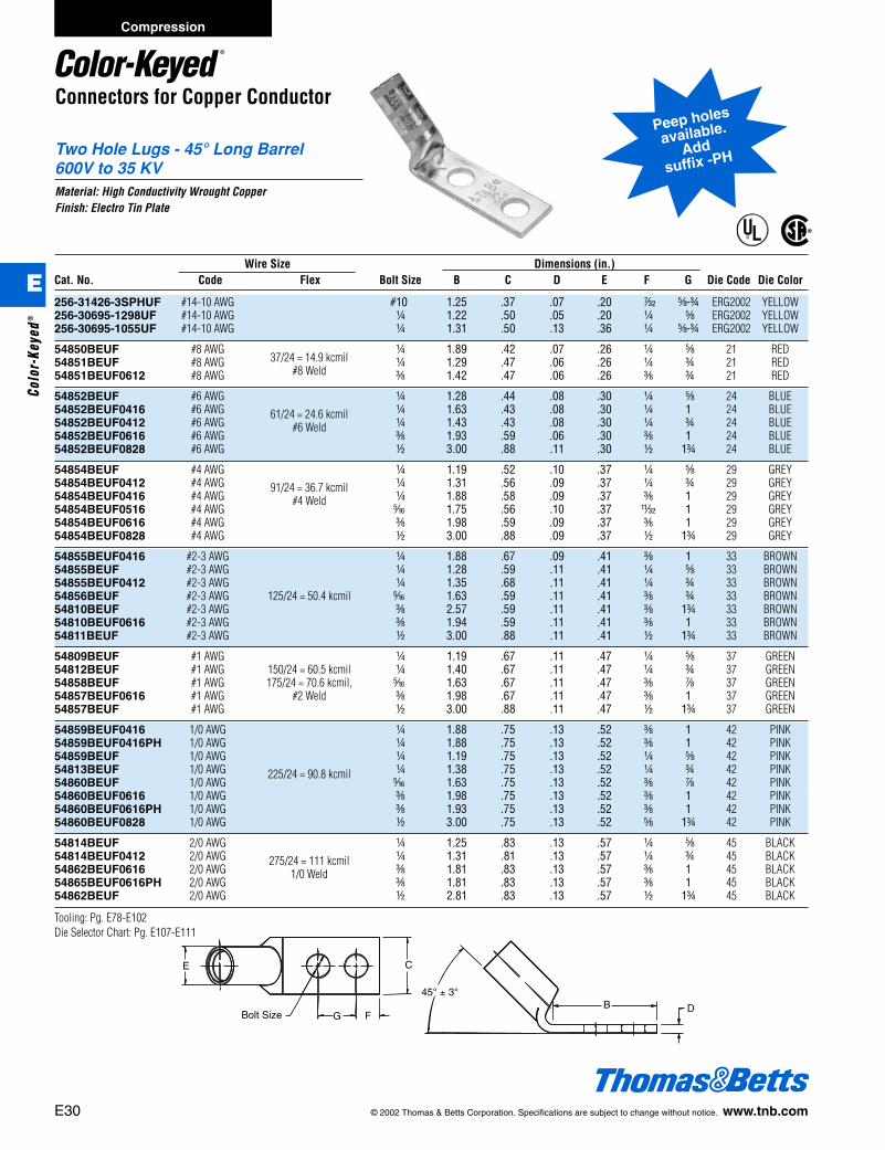
Two Hole Lugs - 45° Long Barrel600V to 35 KVMaterial: High Conductivity Wrought CopperFinish: Electro Tin Plate
®
®
Bolt Size
E C
FG
45° ± 3°
DB
Peep holes
available.
Addsuffix -PH
Wire Size Dimensions (in.)Cat. No. Code Flex Bolt Size B C D E F G Die Code Die Color
256-31426-3SPHUF #14-10 AWG #10 1.25 .37 .07 .20 r e-f ERG2002 YELLOW256-30695-1298UF #14-10 AWG b 1.22 .50 .05 .20 b e ERG2002 YELLOW256-30695-1055UF #14-10 AWG b 1.31 .50 .13 .36 b e-f ERG2002 YELLOW
54850BEUF #8 AWG37/24 = 14.9 kcmil
b 1.89 .42 .07 .26 b e 21 RED54851BEUF #8 AWG
#8 Weldb 1.29 .47 .06 .26 b f 21 RED
54851BEUF0612 #8 AWG c 1.42 .47 .06 .26 c f 21 RED
54852BEUF #6 AWG b 1.28 .44 .08 .30 b e 24 BLUE54852BEUF0416 #6 AWG b 1.63 .43 .08 .30 b 1 24 BLUE54852BEUF0412 #6 AWG
61/24 = 24.6 kcmilb 1.43 .43 .08 .30 b f 24 BLUE
54852BEUF0616 #6 AWG#6 Weld
c 1.93 .59 .06 .30 c 1 24 BLUE54852BEUF0828 #6 AWG d 3.00 .88 .11 .30 d 1f 24 BLUE
54854BEUF #4 AWG b 1.19 .52 .10 .37 b e 29 GREY54854BEUF0412 #4 AWG b 1.31 .56 .09 .37 b f 29 GREY54854BEUF0416 #4 AWG
91/24 = 36.7 kcmilb 1.88 .58 .09 .37 c 1 29 GREY
54854BEUF0516 #4 AWG#4 Weld
j 1.75 .56 .10 .37 X 1 29 GREY54854BEUF0616 #4 AWG c 1.98 .59 .09 .37 c 1 29 GREY54854BEUF0828 #4 AWG d 3.00 .88 .09 .37 d 1f 29 GREY
54855BEUF0416 #2-3 AWG b 1.88 .67 .09 .41 c 1 33 BROWN54855BEUF #2-3 AWG b 1.28 .59 .11 .41 b e 33 BROWN54855BEUF0412 #2-3 AWG b 1.35 .68 .11 .41 b f 33 BROWN54856BEUF #2-3 AWG 125/24 = 50.4 kcmil j 1.63 .59 .11 .41 c f 33 BROWN54810BEUF #2-3 AWG c 2.57 .59 .11 .41 c 1f 33 BROWN54810BEUF0616 #2-3 AWG c 1.94 .59 .11 .41 c 1 33 BROWN54811BEUF #2-3 AWG d 3.00 .88 .11 .41 d 1f 33 BROWN
54809BEUF #1 AWG b 1.19 .67 .11 .47 b e 37 GREEN54812BEUF #1 AWG 150/24 = 60.5 kcmil b 1.40 .67 .11 .47 b f 37 GREEN54858BEUF #1 AWG 175/24 = 70.6 kcmil, j 1.63 .67 .11 .47 c g 37 GREEN54857BEUF0616 #1 AWG #2 Weld c 1.98 .67 .11 .47 c 1 37 GREEN54857BEUF #1 AWG d 3.00 .88 .11 .47 d 1f 37 GREEN
54859BEUF0416 1/0 AWG b 1.88 .75 .13 .52 c 1 42 PINK54859BEUF0416PH 1/0 AWG b 1.88 .75 .13 .52 c 1 42 PINK54859BEUF 1/0 AWG b 1.19 .75 .13 .52 b e 42 PINK54813BEUF 1/0 AWG b 1.38 .75 .13 .52 b f 42 PINK54860BEUF 1/0 AWG
225/24 = 90.8 kcmilj 1.63 .75 .13 .52 c g 42 PINK
54860BEUF0616 1/0 AWG c 1.98 .75 .13 .52 c 1 42 PINK54860BEUF0616PH 1/0 AWG c 1.93 .75 .13 .52 c 1 42 PINK54860BEUF0828 1/0 AWG d 3.00 .75 .13 .52 e 1f 42 PINK
54814BEUF 2/0 AWG b 1.25 .83 .13 .57 b e 45 BLACK54814BEUF0412 2/0 AWG b 1.31 .81 .13 .57 b f 45 BLACK54862BEUF0616 2/0 AWG
275/24 = 111 kcmilc 1.81 .83 .13 .57 c 1 45 BLACK
54865BEUF0616PH 2/0 AWG1/0 Weld
c 1.81 .83 .13 .57 c 1 45 BLACK54862BEUF 2/0 AWG d 2.81 .83 .13 .57 d 1f 45 BLACK
Tooling: Pg. E78-E102Die Selector Chart: Pg. E107-E111
E30 © 2002 Thomas & Betts Corporation. Specifications are subject to change without notice. www.tnb.com
Compression
E
Colo
r-Ke
yed®
412031.E01 CK 3/5 3/13/03 8:22 PM Page 30

Connectors for Copper Conductor
Two Hole Lugs - 45° Long Barrel600V to 35 KV (continued)Material: High Conductivity Wrought CopperFinish: Electro Tin Plate
®
®
Bolt Size
E C
FG
45° ± 3°
DB
Peep holes
available.
Addsuffix -PH
Wire Size Dimensions (in.)Cat. No. Code Flex Bolt Size B C D E F G Die Code Die Color
54815BEUF 3/0 AWG b 1.45 .92 .13 .63 b f 50 ORANGE54816BEUF 3/0 AWG 325/24 = 131 kcmil c 1.63 .92 .13 .63 c 1 50 ORANGE54864BEUF 3/0 AWG d 3.00 .94 .13 .63 d 1f 50 ORANGE
54817BEUF 4/0 AWG b 1.38 1.03 .14 .70 b f 54 PURPLE54818BEUF 4/0 AWG c 2.63 1.03 .14 .70 c 1f 54 PURPLE54818BEUF0616 4/0 AWG
450/24 = 182 kcmilc 1.81 1.03 .14 .70 c 1 54 PURPLE
54818BEUF0616PH 4/0 AWG3/0 Weld
c 1.88 1.03 .14 .70 c 1 54 PURPLE54866BEUF 4/0 AWG d 3.00 1.03 .14 .70 d 1f 54 PURPLE
54868BEUF0616 250 kcmil c 1.93 1.13 .14 .77 c 1 62 YELLOW54868BEUF0616PH 250 kcmil
550/24 = 222 kcmilc 1.93 1.13 .14 .77 c 1 62 YELLOW
54868BEUF 250 kcmil4/0 Weld
d 3.00 1.13 .14 .77 d 1f 62 YELLOW
54819BEUF 300 kcmil c 2.80 1.25 .15 .85 c 1 66 WHITE54870BEUF 300 kcmil 250 d 3.00 1.25 .15 .85 d 1f 66 WHITE
54820BEUF 350 kcmil b 1.93 1.36 .18 .93 b f 71 RED54872BEUF0616 350 kcmil c 1.93 1.36 .18 .93 c 1 71 RED54872BEUF0616PH 350 kcmil 650/24 = 262 kcmil c 1.93 1.36 .18 .93 c 1 71 RED54872BEUF 350 kcmil d 3.00 1.36 .18 .93 d 1f 71 RED
54822BEUF 400 kcmil b 1.93 1.41 .17 .96 b f 76 BLUE54821BEUF 400 kcmil 775/24 = 313 kcmil c 1.93 1.41 .17 .96 c 1 76 BLUE54874BEUF 400 kcmil d 3.00 1.41 .17 .96 d 1f 76 BLUE
54823BEUF 500 kcmil b 1.94 1.61 .22 1.10 b f 87 BROWN54876BEUF0616 500 kcmil c 1.93 1.61 .22 1.10 c 1 87 BROWN54876BEUF0616PH 500 kcmil 925/24 = 373 kcmil c 1.93 1.61 .22 1.10 c 1 87 BROWN54876BEUF 500 kcmil d 3.00 1.61 .22 1.10 d 1f 87 BROWN
54824BEUF 600 kcmil c 2.80 1.75 .24 1.20 c 1 94 GREEN54878BEUF 600 kcmil
1100/24 = 444 kcmild 3.00 1.75 .24 1.20 d 1f 94 GREEN
54880BEUF0616 750 kcmil c 2.06 1.94 .27 1.33 d 1 106 BLACK54880BEUF0616PH 750 kcmil 1325/24 = 535 kcmil c 2.06 1.94 .27 1.33 d 1 106 BLACK54880BEUF 750 kcmil d 3.00 1.94 .27 1.33 d 1f 106 BLACK
58884BEUF 1600/24 = 646 kcmil d 3.00 1.94 .27 1.33 d 1f 106 BLACK
58826BEUF 900 kcmil 1925/24 = 777 kcmil d 3.00 2.18 .31 1.50 d 1f 115 YELLOW
54826BEUF 1000 kcmil c 2.80 2.27 .30 1.55 c 1 125 N/A54882BEUF 1000 kcmil d 3.00 2.27 .30 1.55 d 1f 125 N/A
Tooling: Pg. E78-E102Die Selector Chart: Pg. E107-E111
© 2002 Thomas & Betts Corporation. Specifications are subject to change without notice. www.tnb.com E31
Compression
E
Color-Keyed®
412031.E01 CK 3/5 3/13/03 8:22 PM Page 31
E32 © 2002 Thomas & Betts Corporation. Specifications are subject to change without notice. www.tnb.com
Connectors for Copper Conductor
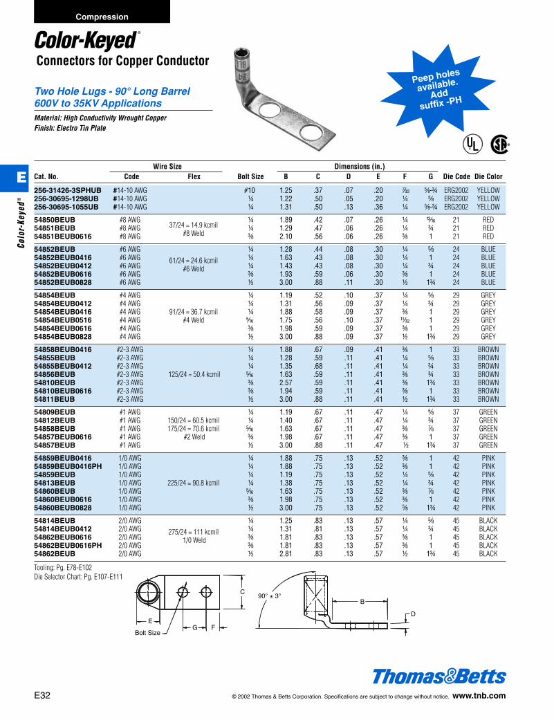
Two Hole Lugs - 90° Long Barrel600V to 35KV ApplicationsMaterial: High Conductivity Wrought CopperFinish: Electro Tin Plate
®
®
Peep holes
available.
Addsuffix -PH
Bolt Size
90° ± 3°B
D
G F
C
E
Bolt Size
90° ± 3°B
D
G F
C
E
Wire Size Dimensions (in.)Cat. No. Code Flex Bolt Size B C D E F G Die Code Die Color
256-31426-3SPHUB #14-10 AWG #10 1.25 .37 .07 .20 r e-f ERG2002 YELLOW256-30695-1298UB #14-10 AWG b 1.22 .50 .05 .20 b e ERG2002 YELLOW256-30695-1055UB #14-10 AWG b 1.31 .50 .13 .36 b e-f ERG2002 YELLOW
54850BEUB #8 AWG37/24 = 14.9 kcmil
b 1.89 .42 .07 .26 b m 21 RED54851BEUB #8 AWG
#8 Weldb 1.29 .47 .06 .26 b f 21 RED
54851BEUB0616 #8 AWG c 2.10 .56 .06 .26 c 1 21 RED
54852BEUB #6 AWG b 1.28 .44 .08 .30 b e 24 BLUE54852BEUB0416 #6 AWG b 1.63 .43 .08 .30 b 1 24 BLUE54852BEUB0412 #6 AWG
61/24 = 24.6 kcmilb 1.43 .43 .08 .30 b f 24 BLUE
54852BEUB0616 #6 AWG#6 Weld
c 1.93 .59 .06 .30 c 1 24 BLUE54852BEUB0828 #6 AWG d 3.00 .88 .11 .30 d 1f 24 BLUE
54854BEUB #4 AWG b 1.19 .52 .10 .37 b e 29 GREY54854BEUB0412 #4 AWG b 1.31 .56 .09 .37 b f 29 GREY54854BEUB0416 #4 AWG 91/24 = 36.7 kcmil b 1.88 .58 .09 .37 c 1 29 GREY54854BEUB0516 #4 AWG #4 Weld j 1.75 .56 .10 .37 X 1 29 GREY54854BEUB0616 #4 AWG c 1.98 .59 .09 .37 c 1 29 GREY54854BEUB0828 #4 AWG d 3.00 .88 .09 .37 d 1f 29 GREY
54858BEUB0416 #2-3 AWG b 1.88 .67 .09 .41 c 1 33 BROWN54855BEUB #2-3 AWG b 1.28 .59 .11 .41 b e 33 BROWN54855BEUB0412 #2-3 AWG b 1.35 .68 .11 .41 b f 33 BROWN54856BEUB #2-3 AWG 125/24 = 50.4 kcmil j 1.63 .59 .11 .41 c f 33 BROWN54810BEUB #2-3 AWG c 2.57 .59 .11 .41 c 1f 33 BROWN54810BEUB0616 #2-3 AWG c 1.94 .59 .11 .41 c 1 33 BROWN54811BEUB #2-3 AWG d 3.00 .88 .11 .41 d 1f 33 BROWN
54809BEUB #1 AWG b 1.19 .67 .11 .47 b e 37 GREEN54812BEUB #1 AWG 150/24 = 60.5 kcmil b 1.40 .67 .11 .47 b f 37 GREEN54858BEUB #1 AWG 175/24 = 70.6 kcmil j 1.63 .67 .11 .47 c g 37 GREEN54857BEUB0616 #1 AWG #2 Weld c 1.98 .67 .11 .47 c 1 37 GREEN54857BEUB #1 AWG d 3.00 .88 .11 .47 d 1f 37 GREEN
54859BEUB0416 1/0 AWG b 1.88 .75 .13 .52 c 1 42 PINK54859BEUB0416PH 1/0 AWG b 1.88 .75 .13 .52 c 1 42 PINK54859BEUB 1/0 AWG b 1.19 .75 .13 .52 b e 42 PINK54813BEUB 1/0 AWG 225/24 = 90.8 kcmil b 1.38 .75 .13 .52 b f 42 PINK54860BEUB 1/0 AWG j 1.63 .75 .13 .52 c g 42 PINK54860BEUB0616 1/0 AWG c 1.98 .75 .13 .52 c 1 42 PINK54860BEUB0828 1/0 AWG d 3.00 .75 .13 .52 e 1f 42 PINK
54814BEUB 2/0 AWG b 1.25 .83 .13 .57 b e 45 BLACK54814BEUB0412 2/0 AWG b 1.31 .81 .13 .57 b f 45 BLACK54862BEUB0616 2/0 AWG
275/24 = 111 kcmilc 1.81 .83 .13 .57 c 1 45 BLACK
54862BEUB0616PH 2/0 AWG1/0 Weld
c 1.81 .83 .13 .57 c 1 45 BLACK54862BEUB 2/0 AWG d 2.81 .83 .13 .57 d 1f 45 BLACK
Tooling: Pg. E78-E102Die Selector Chart: Pg. E107-E111
Compression
E
Colo
r-Ke
yed®
412031.E01 CK 3/5 3/13/03 8:22 PM Page 32
© 2002 Thomas & Betts Corporation. Specifications are subject to change without notice. www.tnb.com E33
Connectors for Copper Conductor
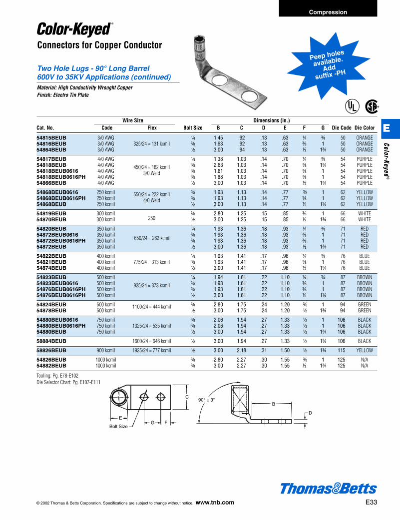
Two Hole Lugs - 90° Long Barrel600V to 35KV Applications (continued)Material: High Conductivity Wrought CopperFinish: Electro Tin Plate
®
®
Bolt Size
90° ± 3°B
D
G F
C
E
Peep holes
available.
Addsuffix -PH
Wire Size Dimensions (in.)Cat. No. Code Flex Bolt Size B C D E F G Die Code Die Color
54815BEUB 3/0 AWG b 1.45 .92 .13 .63 b f 50 ORANGE54816BEUB 3/0 AWG 325/24 = 131 kcmil c 1.63 .92 .13 .63 c 1 50 ORANGE54864BEUB 3/0 AWG d 3.00 .94 .13 .63 d 1f 50 ORANGE
54817BEUB 4/0 AWG b 1.38 1.03 .14 .70 b f 54 PURPLE54818BEUB 4/0 AWG c 2.63 1.03 .14 .70 c 1f 54 PURPLE54818BEUB0616 4/0 AWG
450/24 = 182 kcmilc 1.81 1.03 .14 .70 c 1 54 PURPLE
54818BEUB0616PH 4/0 AWG3/0 Weld
c 1.88 1.03 .14 .70 c 1 54 PURPLE54866BEUB 4/0 AWG d 3.00 1.03 .14 .70 d 1f 54 PURPLE
54868BEUB0616 250 kcmil c 1.93 1.13 .14 .77 c 1 62 YELLOW54868BEUB0616PH 250 kcmil
550/24 = 222 kcmilc 1.93 1.13 .14 .77 c 1 62 YELLOW
54868BEUB 250 kcmil4/0 Weld
d 3.00 1.13 .14 .77 d 1f 62 YELLOW
54819BEUB 300 kcmil c 2.80 1.25 .15 .85 c 1 66 WHITE54870BEUB 300 kcmil 250 d 3.00 1.25 .15 .85 d 1f 66 WHITE
54820BEUB 350 kcmil b 1.93 1.36 .18 .93 b f 71 RED54872BEUB0616 350 kcmil c 1.93 1.36 .18 .93 c 1 71 RED54872BEUB0616PH 350 kcmil 650/24 = 262 kcmil c 1.93 1.36 .18 .93 c 1 71 RED54872BEUB 350 kcmil d 3.00 1.36 .18 .93 d 1f 71 RED
54822BEUB 400 kcmil b 1.93 1.41 .17 .96 b f 76 BLUE54821BEUB 400 kcmil 775/24 = 313 kcmil c 1.93 1.41 .17 .96 c 1 76 BLUE54874BEUB 400 kcmil d 3.00 1.41 .17 .96 d 1f 76 BLUE
54823BEUB 500 kcmil b 1.94 1.61 .22 1.10 b f 87 BROWN54823BEUB0616 500 kcmil c 1.93 1.61 .22 1.10 c 1 87 BROWN54876BEUB0616PH 500 kcmil
925/24 = 373 kcmilc 1.93 1.61 .22 1.10 c 1 87 BROWN
54876BEUB0616PH 500 kcmil d 3.00 1.61 .22 1.10 d 1f 87 BROWN
54824BEUB 600 kcmil c 2.80 1.75 .24 1.20 c 1 94 GREEN54878BEUB 600 kcmil
1100/24 = 444 kcmild 3.00 1.75 .24 1.20 d 1f 94 GREEN
54880BEUB0616 750 kcmil c 2.06 1.94 .27 1.33 d 1 106 BLACK54880BEUB0616PH 750 kcmil 1325/24 = 535 kcmil c 2.06 1.94 .27 1.33 d 1 106 BLACK54880BEUB 750 kcmil d 3.00 1.94 .27 1.33 d 1f 106 BLACK
58884BEUB 1600/24 = 646 kcmil d 3.00 1.94 .27 1.33 d 1f 106 BLACK
58826BEUB 900 kcmil 1925/24 = 777 kcmil d 3.00 2.18 .31 1.50 d 1f 115 YELLOW
54826BEUB 1000 kcmil c 2.80 2.27 .30 1.55 c 1 125 N/A54882BEUB 1000 kcmil c 3.00 2.27 .30 1.55 d 1f 125 N/A
Tooling: Pg. E78-E102Die Selector Chart: Pg. E107-E111
Compression
E
Color-Keyed®
412031.E01 CK 3/5 3/13/03 8:22 PM Page 33
Connectors for Copper Conductor
Two-Way Splice Connectors - Long Barrel600V to 35KV ApplicationsMaterial: High Conductivity Wrought CopperFinish: Electro Tin Plate
®
®
E DIA.
54 DIE
PURPLE
54 DIE
PURPLE 54 D
IE
PURP
LE
54 D
IE
PURP
LE
T&B
4/0
E34 © 2002 Thomas & Betts Corporation. Specifications are subject to change without notice. www.tnb.com
Compression
E
Colo
r-Ke
yed®
Wire Size Dimensions (in.)Cat. No. Code Flex A E Die Code Die Color
54804 #8 AWG 37/24 = 14.9 kcmil 1.75 .27 21 RED
54805 #6 AWG 61/24 = 24.6 kcmil 1.75 .31 24 BLUE
54806 #4 AWG 91/24 = 36.7 kcmil 1.75 .39 29 GREY
54807 #2 AWG 125/24 = 50.4 kcmil 1.88 .43 33 BROWN
54808 #1 AWG 150/24 = 60.5 kcmil, 175/24 = 70.6 kcmil 2.00 .49 37 GREEN
54809 1/0 AWG 225/24 = 90.8 kcmil 2.00 .54 42 PINK
54810 2/0 AWG 275/24 = 111 kcmil 2.13 .59 45 BLACK
54811 3/0 AWG 325/24 = 131 kcmil 2.25 .65 50 ORANGE
54812 4/0 AWG 450/24 = 182 kcmil 2.75 .72 54 PURPLE
54813 250 kcmil 550/24 = 222 kcmil 3.38 .79 62 YELLOW
54814 300 kcmil 3.50 .87 66 WHITE
54815 350 kcmil 650/24 = 262 kcmil 3.75 .95 71 RED
54816 400 kcmil 775/24 = 313 kcmil 3.75 .98 76 BLUE
54818 500 kcmil 925/24 = 373 kcmil 4.75 1.11 87 BROWN
54820 600 kcmil 1100/24 = 444 kcmil 4.25 1.21 94 GREEN
54823 750 kcmil 1325/24 = 535 kcmil 4.75 1.34 106 BLACK
58524 1600/24 = 646 kcmil 5.00 1.39 106 BLACK
58526 900 kcmil 1925/24 = 777 kcmil 5.50 1.51 115 YELLOW
54828 1000 kcmil 5.63 1.56 125 N/A
54839 2000 kcmil 7.06 2.125
Tooling: Pg. E78-E102Die Selector Chart: Pg. E107-E111
412031.E01 CK 3/5 3/13/03 8:22 PM Page 34

© 2002 Thomas & Betts Corporation. Specifications are subject to change without notice. www.tnb.com E35
Compression
E
Color-Keyed®
Bell Shaped BarrelWire Size* Class Class Class Class Class Bolt Dimensions (in.) Die Die
Cat. No. Code Navy Flex G H I K M Size (in.) A B C D F Color Code
541048BS 8 23 37/24 8 8 – 8 8 #10 1h v u Z r Red 21541056BS 6 30 61/24 5 5 5 5 5 b 1i l k ƒ b Blue 24541065BS 4 40-50 91/24 5 5 5 5 5 b 1s l l ƒ b Grey 29541394BS 3 & 4 40-50 91/24 4 4 4 4 4 j 1k A x Z X Grey 29541423BS 2 60 125/24 3 3 3 3 3 j 1w z y Z X Brown 33541472BS 1 75 150, 175/24 2 2 2 2 2 j 1y z H a c Green 37541531BS 1/0 100 225/24 1 1 1 1 1 j 1e z f ! c PInk 425411010BS 2/0 125 275/24 1/0 1/0 1/0 1/0 1/0 c 1g m m ! c Black 455416520BS 3/0 150 325/24 2/0 2/0 2/0 2/0 2/0 d 2r 1h n ! d Orange 505417030BS 4/0 200 450/24 3/0 3/0 3/0 3/0 3/0 d 2j 1h 1o q d Purple 545816540BS 250 – 550/24 4/0 4/0 – – – d 2v 1a 1b i d Yellow 6254114262BS 300 300 650/24 250 250 250 250 – d 2v 1a 1b i d White 665411440BS 300 300 – 250 250 4/0 4/0 4/0 d 2c 1a 1b i d White 6654115260BS 350 350 650/24 – – 250 250 250 d 2e 1i 1c $ l White 6654185313BS 400 400 775/24 300 300 300 300 300 e 3k 1L 1u r m Blue 7658177350BS 500 – 925/24 400 400 400 350 350 e 3 1j 1e b m N/A 8058180444BS 600 – 1100/24 – – 450 450 450 e 3e 1L 1A å m Green 9454122535BS 700 – 1325/24 500 500 500 500 500 e 3e 1L 1A s m Pink 9954123600BS 750 – – 600 – – – 550 e 3e 1L 1n j m Black 10654124800BS 800 800 – – – – 600 – e 3m 1L 2 j e Orange 10754126777BS 900 – 1925/24 – – – – – e 4a 1m 2i X g Yellow 115
Connectors for Copper Conductor
®
®
Standard Barrel – Belled End Lugs
Bolt Size
B
D
A
F
C
Existing Connectors New Series**Are UL486A Listed For: (Same Tubing
Existing As ExistingCat. Nos. Code Navy Flex Cat. Nos.) Class G Class H Class I Class K Class M Code
54104 8 23 37/24 541048BS 8 8 – 8 8 –54105 6 30 61/24 541056BS 5 5 5 5 5 –54106 4 40-50 91/24 541065BS 5 5 5 5 5 –54139 4 40-50 91/24 541394BS 4 4 4 4 4 354142 2 60 125/24 541423BS 3 3 3 3 3 –54147 1 75 150, 175/24 541472BS 2 2 2 2 2 –54153 1/0 100 225/24 541531BS 1 1 1 1 1 –54110 2/0 125 275/24 5411010BS 1/0 1/0 1/0 1/0 1/0 –54165 3/0 150 325/24 5416520BS 2/0 2/0 2/0 2/0 2/0 –54170 4/0 200 450/24 5417030BS 3/0 3/0 3/0 3/0 3/0 –58165 – – 550/24 5816540BS 4/0 4/0 – – – 25054114 300 300 – 5411440BS 250 250 4/0 4/0 4/0 –54115 350 350 650/24 54115260BS – – 250 250 250 –54185 400 400 775/24 54185313BS 300 300 300 300 300 –58177 – – 925/24 58177350BS 400 400 400 350 350 50058180* – – 1100/24 58180444BS – – 450 450 450 60054122 700 – 1325/24 54122535BS 500 500 500 500 500 –54123 750 – – 54123560BS 600 – – – 550 –54124 800 800 – 54124620BS – – – – 600 –54126 900 – 1925/24 54126777BS – – – – – –
** = Cat 58180 is made of the same tubing as cat. 54120. Cat. 54120 is listed for 600 mcm.** = To be installed with the same installing tools as the existing line of connectors.Tooling: Pg. E78-E102Die Selector Chart: Pg. E107-E111
412031.E01 CK 3/5 3/13/03 8:22 PM Page 35

E36 © 2002 Thomas & Betts Corporation. Specifications are subject to change without notice. www.tnb.com
Connectors for Copper Conductor
®
®
B
D
Bolt Size G F
CE
A
Long Barrel – Belled End Lugs
Bell Shaped Copper Lugs with Two Bolt HolesWire Size* Class Class Class Class Class Bolt Dimensions (in.) Die Die
Cat. No. Code Navy Flex G H I K M Size (in.) A B C D E F G Color Code
54850BE8BS 8 23 8 8 8 – 8 – b 2.19 1.88 .42 .07 .26 .25 .63 Red 2154851BE8BS 8 23 8 8 8 – 8 – b 2.31 1.29 .47 .06 .26 .25 .75 Red 21256-1157-8BS 8 23 8 8 8 – 8 – c 3.00 2.10 .56 .06 .26 .38 1.00 Red 21256-1158-6BS 6 30 6 5 5 5 5 – c 2.93 1.93 .59 .06 .30 .38 1.00 Blue 2454852BE6BS 6 30 6 5 5 5 5 – b 2.28 1.28 .44 .08 .30 .25 .63 Blue 24256-1225-6BS 6 30 6 5 5 5 5 – b 2.43 1.43 .43 .07 .30 .25 .75 Blue 2454854BE5BS 4-3 40-50 5 5 5 5 5 – b 2.31 1.19 .52 .10 .37 .25 .63 Grey 29256-1246-5BS 4-3 40-50 5 5 5 5 5 – b 2.31 1.31 .56 .09 .37 .25 .75 Grey 29256-1159-5BS 4-3 40-50 5 5 5 5 5 – c 3.13 1.98 .59 .09 .37 .38 1.00 Grey 29256-1300-3BS 2 60 3 3 3 3 3 3 b 2.63 1.35 .68 .11 .41 .25 .75 Brown 3354855BE3BS 2 60 3 3 3 3 3 3 b 2.43 1.28 .59 .11 .41 .25 .63 Brown 3354856BE3BS 2 60 3 3 3 3 3 3 j 2.78 1.63 .59 .11 .41 ..38 .75 Brown 33256-1160-3BS 2 60 3 3 3 3 3 3 c 3.08 1.94 .59 .11 .41. .38 1.00 Brown 3354811BE3BS 2 60 3 3 3 3 3 3 d 4.28 3.00 .88 .09 .41 .50 1.75 Brown 3354809BE2BS 1 75 2 2 2 2 2 2 b 2.88 1.19 .67 .11 .47 .25 .63 Green 3754812BE2BS 1 75 2 2 2 2 2 2 b 2.75 1.40 .67 .11 .47 .25 .75 Green 3754858BE2BS 1 75 2 2 2 2 2 2 j 2.97 1.63 .67 .11 .47 .38 .88 Green 3754857BE2BS 1 75 2 2 2 2 2 2 d 4.43 3.00 .88 .10 .47 .50 1.75 Green 3754859BE1BS 1/0 100 1 1 1 1 1 1 b 2.63 1.19 .75 .13 .52 .25 .63 Pink 4254813BE1BS 1/0 100 1 1 1 1 1 1 b 2.71 1.38 .75 .13 .52 .25 .75 Pink 4254860BE1BS 1/0 100 1 1 1 1 1 1 j 2.97 1.63 .75 .13 .52 .38 .88 Pink 42256-1162-1BS 1/0 100 1 1 1 1 1 1 c 3.23 1.93 .75 .13 .52 .38 1.00 Pink 425414BE10BS 2/0 125 1/0 1/0 1/0 1/0 1/0 1/0 b 2.62 1.25 .83 .13 .57 .25 .63 Black 45256-1299-10BS 2/0 125 1/0 1/0 1/0 1/0 1/0 1/0 b 2.69 1.31 .81 .13 .57 .25 .75 Black 45256-1116-10BS 2/0 125 1/0 1/0 1/0 1/0 1/0 1/0 c 3.19 1.81 .83 .13 .57 .38 1.00 Black 4554862BE10BS 2/0 125 1/0 1/0 1/0 1/0 1/0 1/0 d 4.20 2.81 .83 .13 .57 .50 1.75 Black 4554815BE20BS 3/0 150 2/0 2/0 2/0 2/0 2/0 2/0 b 2.89 1.45 .92 .13 .63 .25 .75 Orange 5054816BE20BS 3/0 150 2/0 2/0 2/0 2/0 2/0 2/0 c 3.25 1.63 .92 .13 .63 .38 1.00 Orange 5054864BE20BS 3/0 150 2/0 2/0 2/0 2/0 2/0 2/0 d 4.45 3.00 .92 .13 .63 .50 1.75 Orange 5054817BE30BS 4/0 200 3/0 3/0 3/0 3/0 3/0 3/0 b 3.15 1.38 1.03 .14 .70 .50 .75 Purple 54256-1117-30BS 4/0 200 3/0 3/0 3/0 3/0 3/0 3/0 c 3.35 1.81 1.03 .14 .70 .25 1.00 Purple 5454818BE30BS 4/0 200 3/0 3/0 3/0 3/0 3/0 3/0 c 4.38 2.63 1.03 .14 .70 .38 1.75 Purple 5454866BE30BS 4/0 200 3/0 3/0 3/0 3/0 3/0 3/0 d 4.70 3.00 1.03 .14 .70 .50 1.75 Purple 54256-1245-40BS 250 – 4/0 4/0 4/0 4/0 4/0 4/0 c 3.83 1.93 1.13 .14 .77 .50 1.00 Yellow 6254868BE40BS 250 – 4/0 4/0 4/0 4/0 4/0 4/0 d 4.92 3.00 1.13 .14 .77 .50 1.75 Yellow 6254819BE262BS 300 300 262 kcmil 250 kcmil 250 250 250 – c 5.04 2.80 1.25 .15 .85 .50 1.00 White 6654870BE262BS 300 300 262 kcmil 250 kcmil 250 250 250 – d 5.23 3.00 1.25 .15 .85 .50 1.75 White 6654822BE313BS 400 400 313 kcmil 300 kcmil 300 300 300 – b 4.38 1.93 1.41 .17 .96 .63 .75 Blue 7654821BE313BS 400 400 313 kcmil 300 kcmil 300 300 300 – c 4.43 1.93 1.41 .17 .96 .63 1.00 Blue 7654874BE313BS 400 400 313 kcmil 300 kcmil 300 300 300 – d 5.51 3.00 1.41 .17 .96 .63 1.75 Blue 7654823BE373BS 500 – 373 kcmil 400 kcmil 400 400 350 – b 4.93 1.94 1.61 .22 1.10 .50 .75 Brown 87256-1119-373BS 500 – 373 kcmil 400 kcmil 400 400 350 – c 5.00 1.93 1.61 .22 1.10 .50 1.00 Brown 8754876BE373BS 500 – 373 kcmil 400 kcmil 400 400 350 – d 6.00 3.00 1.61 .22 1.10 .50 1.75 Brown 8754824BE444BS – – 444 kcmil – – 450 450 – c 5.70 2.80 1.75 .24 1.20 .63 1.00 Green 9454878BE444BS – – 444 kcmil – – 450 450 – d 5.83 3.00 1.75 .24 1.20 .63 1.75 Green 9454880BE535BS 700 – 535 kcmil 500 kcmil 500 500 500 – d 6.20 3.00 1.94 .27 1.33 .63 1.75 Black 10658826BE777BS 900 – 777 kcmil – – – – – c 6.49 2.80 2.27 .30 1.50 .63 1.00 Yellow 115
Tooling: Pg. E78-E102Die Selector Chart: Pg. E107-E111
Compression
E
Colo
r-Ke
yed®
412031.E01 CK 3/5 3/13/03 8:22 PM Page 36

© 2002 Thomas & Betts Corporation. Specifications are subject to change without notice. www.tnb.com E37
Connectors for Copper Conductor
Two Barrel Lugs600V to 35KV ApplicationsMaterial: High Conductivity Wrought CopperFinish: Electro Tin Plate
®
®
T&B Wire Size Hole Fig. Dimensions (in.) Die ColorCat. No. Code Flex Size (in.) No. A W T Code Key
256-30695-828 6 61/24 b 1 2n k h 24 Blue
256-30695-1227 6 61/24 b 2 3c k h 24 Blue
Tooling: Pg. E78-E102Die Selector Chart: Pg. E107-E111
Figure 1 Figure 2
Hole Size b"
A
T
.75
W
1.50
Hole Size b"
A
T
1.50
.75
W
60°
Compression
E
Color-Keyed®
412031.E01 CK 3/5 3/13/03 8:22 PM Page 37
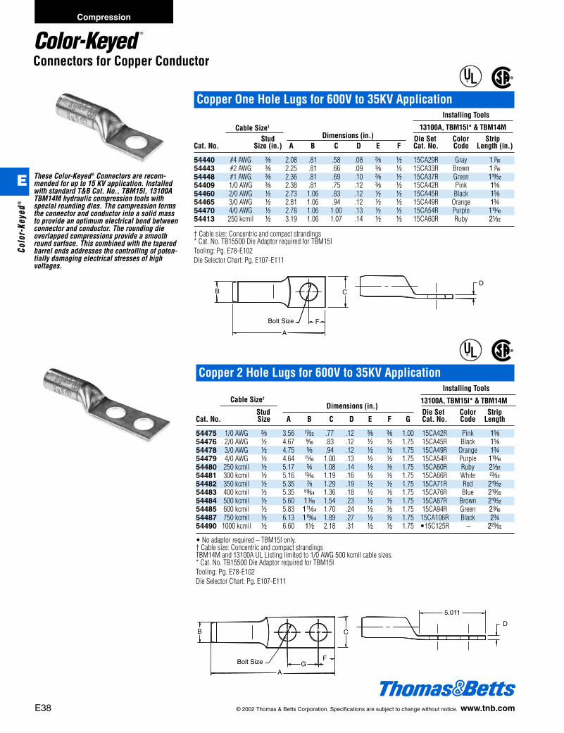
5.011
D
GFBolt Size
A
CB
E38 © 2002 Thomas & Betts Corporation. Specifications are subject to change without notice. www.tnb.com
Compression
E
Colo
r-Ke
yed®
Connectors for Copper Conductor
These Color-Keyed® Connectors are recom-mended for up to 15 KV application. Installedwith standard T&B Cat. No., TBM15I, 13100ATBM14M hydraulic compression tools withspecial rounding dies. The compression formsthe connector and conductor into a solid massto provide an optimum electrical bond betweenconnector and conductor. The rounding dieoverlapped compressions provide a smoothround surface. This combined with the taperedbarrel ends addresses the controlling of poten-tially damaging electrical stresses of highvoltages.
®®
D
Bolt Size
B
F
C
A
Copper 2 Hole Lugs for 600V to 35KV ApplicationInstalling Tools
Cable Size† 13100A, TBM15I* & TBM14MStud
Dimensions (in.)Die Set Color Strip
Cat. No. Size A B C D E F G Cat. No. Code Length
54475 1/0 AWG c 3.56 w .77 .12 c c 1.00 15CA42R Pink 1e54476 2/0 AWG d 4.67 l .83 .12 d d 1.75 15CA45R Black 1e54478 3/0 AWG d 4.75 e .94 .12 d d 1.75 15CA49R Orange 1f54479 4/0 AWG d 4.64 L 1.00 .13 d d 1.75 15CA54R Purple 1m54480 250 kcmil d 5.17 f 1.08 .14 d d 1.75 15CA60R Ruby 2o54481 300 kcmil d 5.16 m 1.19 .16 d d 1.75 15CA66R White z54482 350 kcmil d 5.35 g 1.29 .19 d d 1.75 15CA71R Red 2u54483 400 kcmil d 5.35 ∂ 1.36 .18 d d 1.75 15CA76R Blue 2u54484 500 kcmil d 5.60 1h 1.54 .23 d d 1.75 15CA87R Brown 2u54485 600 kcmil d 5.83 1™ 1.70 .24 d d 1.75 15CA94R Green 2l54487 750 kcmil d 6.13 1∫ 1.89 .27 d d 1.75 15CA106R Black 2f54490 1000 kcmil d 6.60 1d 2.18 .31 d d 1.75 •15C125R – 2C
• No adaptor required – TBM15I only.† Cable size: Concentric and compact strandingsTBM14M and 13100A UL Listing limited to 1/0 AWG 500 kcmil cable sizes.* Cat. No. TB15500 Die Adaptor required for TBM15ITooling: Pg. E78-E102Die Selector Chart: Pg. E107-E111
®
®
Copper One Hole Lugs for 600V to 35KV ApplicationInstalling Tools
Cable Size† 13100A, TBM15I* & TBM14MStud Dimensions (in.) Die Set Color Strip
Cat. No. Size (in.) A B C D E F Cat. No. Code Length (in.)
54440 #4 AWG c 2.08 .81 .58 .08 c d 15CA29R Gray 1k54443 #2 AWG c 2.25 .81 .66 .09 c d 15CA33R Brown 1k54448 #1 AWG c 2.36 .81 .69 .10 c d 15CA37R Green 1x54409 1/0 AWG c 2.38 .81 .75 .12 c d 15CA42R Pink 1e54460 2/0 AWG d 2.73 1.06 .83 .12 d d 15CA45R Black 1e54465 3/0 AWG d 2.81 1.06 .94 .12 d d 15CA49R Orange 1f54470 4/0 AWG d 2.78 1.06 1.00 .13 d d 15CA54R Purple 1m54413 250 kcmil d 3.19 1.06 1.07 .14 d d 15CA60R Ruby 2o
† Cable size: Concentric and compact strandings* Cat. No. TB15500 Die Adaptor required for TBM15ITooling: Pg. E78-E102Die Selector Chart: Pg. E107-E111
412031.E01 CK 3/5 3/13/03 8:22 PM Page 38

© 2002 Thomas & Betts Corporation. Specifications are subject to change without notice. www.tnb.com E39
Compression
E
Color-Keyed®
Connectors for Copper Conductor®
®
A
B
Copper Two-Way Splicers for up to 600V to 35KV ApplicationInstalling Tools
13100A, TBM15I* & TBM14MCable+
Dimensions (in.)Die Set Color Strip
Cat. No. Size A B Cat. No. Code Length (in.)
54006 #4 AWG 2.00 .37 15CA29R Gray 1d54007 #2 AWG 2.13 .41 15CA33R Brown 1e54008 #1 AWG 2.25 .47 15CA37R Green 1e54009 1/0 AWG 2.38 .52 15CA42R Pink 1f54010 2/0 AWG 2.38 .57 15CA45R Black 1f54011 3/0 AWG 2.63 .63 15CA49R Orange 1m54012 4/0 AWG 2.69 .69 15CA54R Purple 1m54013 250 kcmil 3.19 .74 15CA60R Ruby 2a54015 350 kcmil 4.13 .89 15CA71R Red 2e54018 500 kcmil 4.13 1.06 15CA87R Brown 2e54023 750 kcmil 4.75 1.30 15CA106R Black 2g
* Cat. No. 15500-TB Die Adaptor required for TBM15I + Cable Size: Concentric and Compact strandingsTooling: Pg. E78-E102Die Selector Chart: Pg. E107-E111
412031.E01 CK 3/5 3/13/03 8:22 PM Page 39

E40 © 2002 Thomas & Betts Corporation. Specifications are subject to change without notice. www.tnb.com
Cast Copper Connectors for Copper Conductor
Cast Copper One Hole Lugs 600V to 35KV Applications –Heavy Duty
Cable Dimensions (in.) Bolt DieCat. No. Size A B C D F Size (in.) Code
53104 8 1k f d a s #10 2953105 6 1k f d a s b 2953106 4 1k f d a s b 29
53107 2 2 1 f b k b 4553108 1 2 1 f b k b 4553109 1/0 2 1 f b k c 45
53161** 325/24 2i f m r k c 54
53110 2/0 2e 1b 1 s w c 6653111 3/0 2e 1b 1 s w c 6653112 4/0 2e 1b 1 s w c 66
53165** 650/24 3h 1c 1i j f d 7653113 250 kcmil 3h 1d 1i j f d 7653114 300 kcmil 3h 1d 1i j f d 76
53115 350 kcmil 3m 2 1c c m d 9953116 400 kcmil 3m 2 1c c m d 9953118 500 kcmil 3m 2 1c c m d 99
53168** 1100/24 3j 1e 1e u g d 10753169** 1325/24 3j 1e 1e u g d 107
53123 750 kcmil 4i 2a 1e k 1 d 112
53173** 2750/24* 5h 1g 2a l 1i d 150
All other Cat No: Use hydraulic tools with hex dies.** No U.L./CSATooling: Pg. E78-E102Die Selector Chart: Pg. E107-E111
Material – Cast CopperFinish – Electro-Tin Plated
®
®
ED
C
F
B
A
Bolt size
Compression
E
Colo
r-Ke
yed®
412031.E01 CK 3/5 3/13/03 8:22 PM Page 40
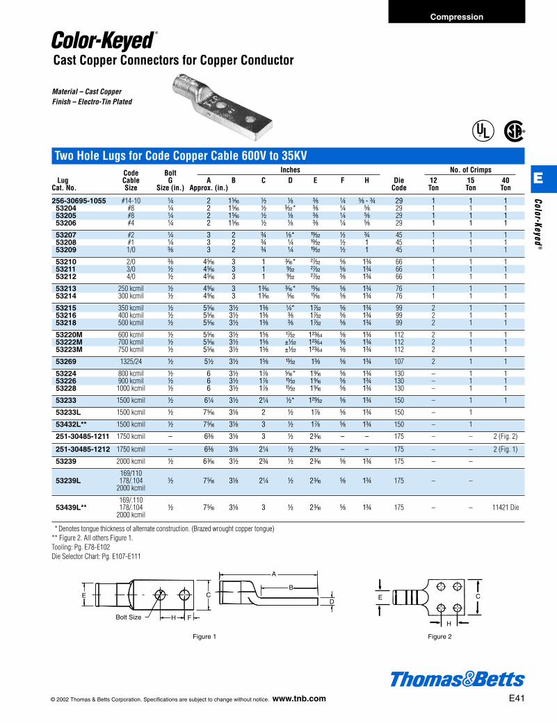
© 2002 Thomas & Betts Corporation. Specifications are subject to change without notice. www.tnb.com E41
Two Hole Lugs for Code Copper Cable 600V to 35KV Code Bolt Inches No. of Crimps
Lug Cable G A B C D E F H Die 12 15 40Cat. No. Size Size (in.) Approx. (in.) Code Ton Ton Ton
256-30695-1055 #14-10 b 2 1j d a c b e - f 29 1 1 153204 #8 b 2 1j d p* c b e 29 1 1 153205 #8 b 2 1j d a c b e 29 1 1 153206 #4 b 2 1j d a c b e 29 1 1 1
53207 #2 b 3 2 f a* x d f 45 1 1 153208 #1 b 3 2 f b x d 1 45 1 1 153209 1/0 c 3 2 f b x d 1 45 1 1 1
53210 2/0 c 4j 3 1 i* B e 1f 66 1 1 153211 3/0 d 4j 3 1 s B e 1f 66 1 1 153212 4/0 d 4j 3 1 s B e 1f 66 1 1 1
53213 250 kcmil d 4l 3 1i i* n e 1f 76 1 1 153214 300 kcmil d 4l 3 1i j n e 1f 76 1 1 1
53215 350 kcmil d 5j 3d 1c b* 1r e 1f 99 2 1 153216 400 kcmil d 5j 3d 1c c 1r e 1f 99 2 1 153218 500 kcmil d 5j 3d 1c c 1r e 1f 99 2 1 1
53220M 600 kcmil d 5j 3d 1e w 1R e 1f 112 2 1 153222M 700 kcmil d 5j 3d 1e ±o 1R e 1f 112 2 1 153223M 750 kcmil d 5j 3d 1e ±o 1R e 1f 112 2 1 1
53269 1325/24 d 5d 3d 1e u 1c e 1f 107 2 1 1
53224 800 kcmil d 6 3d 1g j* 1l e 1f 130 – 1 153226 900 kcmil d 6 3d 1g v 1l e 1f 130 – 1 153228 1000 kcmil d 6 3d 1g v 1l e 1f 130 – 1 1
53233 1500 kcmil d 6b 3d 2b d* 1C e 1f 150 – 1 1
53233L 1500 kcmil d 7j 3a 2 d 1g e 1f 150 – 1
53432L** 1500 kcmil d 7j 3a 3 d 1g e 1f 150 – 1
251-30485-1211 1750 kcmil – 6c 3a 3 d 2i – – 175 – – 2 (Fig. 2)
251-30485-1212 1750 kcmil – 6c 3a 2b d 2i – – 175 – – 2 (Fig. 1)
53239 2000 kcmil d 6i 3d 2f d 2i e 1f 175 – –
169/11053239L 178/.104 d 7j 3a 2b d 2i e 1f 175 – –
2000 kcmil
169/.11053439L** 178/.104 d 7j 3a 3 d 2i e 1f 175 – – 11421 Die
2000 kcmil
** Denotes tongue thickness of alternate construction. (Brazed wrought copper tongue)** Figure 2. All others Figure 1.Tooling: Pg. E78-E102Die Selector Chart: Pg. E107-E111
Material – Cast CopperFinish – Electro-Tin Plated
®
®
Bolt Size
D
B
A
E
H F
C
Cast Copper Connectors for Copper Conductor
E C
H
Figure 1 Figure 2
Compression
E
Color-Keyed®
412031.E01 CK 3/5 3/13/03 8:22 PM Page 41

E42 © 2002 Thomas & Betts Corporation. Specifications are subject to change without notice. www.tnb.com
Cast Copper Connectors for Copper Conductor
Cast Copper Two Way Connector 600V – 35KVApplications – Heavy Duty
Cable DieCat. No. Size Code
53504 8AWG 2953505 6AWG 2953506 4AWG 2953507 2AWG 4553508 1AWG 45
53509 1/0AWG 4553510 2/0AWG 6653511 3/0AWG 6653512 4/0AWG 6653513 250 kcmil 76
53515 350 kcmil 9953518 500 kcmil 9953523 750 kcmil 112
Use hydraulic tools with hex dies.Tooling: Pg. E78-E102Die Selector Chart: Pg. E107-E111
®
Satisfies requirements of NEC250-81 and 250-91 for connecting to the grounding electrode system.
Material – Cast CopperFinish – Electro-Tin Plated
Compression
E
Colo
r-Ke
yed®
412031.E01 CK 3/5 3/13/03 8:22 PM Page 42

© 2002 Thomas & Betts Corporation. Specifications are subject to change without notice. www.tnb.com E43

90° Flag Lugs – 600V, 90°CT&B CU Stud Dimensions (in.) Die
Cat. No. Cable Size Size (in.) Phase A B C D E F G Code1 1.38
10A-FT-14NTK 1/0 b 2 2.13 .94 .64 .19 .62 .25 2.50 503 2.88
1 1.9320A-FT-14NTK 2/0 b 2 2.93 1.14 .64 .22 .70 .25 2.50 54
3 3.93
1 2.1130A-FT-14NTK 3/0 b 2 3.11 1.14 .78 .22 .77 .25 2.75 60
3 4.11
1 2.0440A-FT-14NTK 4/0 b 2 3.04 1.14 .78 .25 .86 .25 3.13 66
3 4.04
1 2.31250A-FT-14NTK 250 kcmil b 2 3.44 1.20 .98 .25 .92 .31 3.00 71
3 4.57
1 2.31350A-FT-12NTK 350 kcmil b 2 3.69 1.45 1.09 .31 1.09 .56 3.94 87
3 5.06
1 2.56500A-FT-12NTK 500 kcmil b 2 4.06 1.45 1.20 .38 1.28 .56 4.19 99
3 5.69
1 2.63750A-FT-58NTK 750 kcmil b 2 4.50 1.70 1.49 .38 1.50 .81 4.39 115
3 6.25
* Each Cat. No. consists of three connectors, (1) connector per phase.Connectors supplied with Thomas & Betts oxide inhibitor compound in wire bore.Note: 1) Each Cat. No. consists of three connectors, (1) connector per phase.Installation tooling: Hand or hydraulic tools.Tooling: Pg. E78-E102Die Selector Chart: Pg. E107-E111
Material: AluminumFinish: Tin PlateInsulation: PVC dip coated
®®
FA
C
B
90°
G
E
D
T&
B
Flag Connectors for Aluminum Conductor
E44 © 2002 Thomas & Betts Corporation. Specifications are subject to change without notice. www.tnb.com
Compression
E
Colo
r-Ke
yed®
412031.E01 CK 3/5 3/13/03 8:22 PM Page 44

C-Tap Connectors for Copper Conductor
C-Taps 600V ApplicationsMaterial: High Conductivity Wrought CopperFinish: Plain
These taps assure positive, all around compres-sion with low resistance and high pullout values.Made of high conductivity wrought copper, theycontain heavy reinforcing ribs which locate thecompression dies as well as strengthen thecompressed joint. Ideal for pigtailing, 2-waysplicing, or tapping to an unbroken continuousmain.
Typical Cable CombinationsBranch
#12 Sol #10 Sol #8 Sol #6 SolMAIN or Str or Str or Str or Str #4 Str #2 Str #1 Str 1/0 Str
#10 Sol or Str 54705 54710 54715 54715 54720 54730 54735 54740#8 Sol or Str 54710 54715 54715 54720 54720 54730 54735 54740#6 Sol or Str 54715 54715 54720 54720 54725 54730 54735 54740
#4 Str 54720 54720 54720 54725 54730 54735 54740 54740#2Str 54730 54730 54730 54730 54735 54740 54745 54745#1 Str 54735 54735 54735 54735 54740 54745 54745 547501/0 Str 54740 54740 54740 54740 5i740 54745 54750 547502/0 Str 54745 54745 54745 54745 54745 54750 547503/0 Str 54750 54750 54750 54750 54750 54750
Tooling: Pg. E78-E102Die Selector Chart: Pg. E107-E111
E H
L
Fig. Dimensions (Inches) ColorCat. No. No. L H E Key
54705 1 j j ƒ Red
54710 1 l k ! Blue
54715 1 l e ™ Gray
54720 2 1q W r Brown
54725 2 1q m b Green
54730 2 1q B s Pink
54735 3 1W g Q Black
54740 3 1W O R Orange
54745 3 1W 1h u Purple
54750 3 1W 1i v Yellow
NOTES:UL approved for direct burial.For covers see page E50.Taps can be supplied tin-plated. Add suffix - TP to any catalog number (i.e.54725TP).
“E” represents gap in side.
®
®
E H
L L
E H
Figure 1 Figure 2 Figure 3
© 2002 Thomas & Betts Corporation. Specifications are subject to change without notice. www.tnb.com E45
Compression
E
Color-Keyed®
412031.E01 CK 3/5 3/13/03 8:22 PM Page 45

Wire Size Dimensions (In.) Installing DieDie No. of Color
Cat. No. Main Branch C D E Tool Cat No. Code Crimps Key
#1 #11/0 1/0-#2 TBM14M 15512 76
54755 2/0 2/0-#4 1n f w TBM15I 15512* 76 1 Blue3/0 1/0-#6 TBM12 TBM12D-4 764/0 #1-#8 13100A 15512 76
2/0 2/0-#1 TBM14M 15506 87H
547603/0 3/0-#3
1k f xTBM15I 15506* 87H
2 Brown4/0 4/0-#4 TBM12 TBM12D-3 87H250 kcmil #1-#8 13100A 15506 87H
2/0 2/0-#13/0 3/0-#2 TBM14M 15505 99H
54765 4/0 4/0-#4 1L 1 G TBM15I 15505* 99H 2 Pink250 kcmil 3/0-#6 TBM12 TBM12D-2 99H300 kcmil 2/0-#8 13100A 15505 99H
4/0 4/0-2/0 TBM14M 15515 106H
54770250 kcmil 250-#1
1L 1 LTBM15I 15515* 106H
2 Black300 kcmil 4/0-#4 TBM12 TBM12D-2 106H350 kcmil 3/0-#6 13100A 15515 106H
250 kcmil 250kcmil300 kcmil 300-3/0 TBM14M 15504 115H
54775**350 kcmil 350-1/0
1g 1b mTBM15I 15504* 115H
2 Yellow400 kcmil 300-#2 TBM12 TBM12D-1 115H450 kcmil 250-#4 13100A 15504 115H500 kcmil 250-#6
350 kcmil 350-4/054780 400 kcmil 400-2/0 2i 1b K TBM15I 15603 125H 2 N/A
450 kcmil 450-#1500 kcmil 500-#2
54785 750 kcmil 4/0-#6 2a 2 1 TBM15I 15603 125H 3 N/A
54790 750 kcmil 750-4/0 2L 2 1j TBM15I 15603 125H 3 N/A
NOTES:UL approved for direct burial.For covers see page E50.Taps can be supplied tin-plated. Add suffix - TP to any catalog number (i.e. 54725TP).*Cat. No. 15500-TB adapter required if using TBM15I and 155XX series dies.**#6 AWG branch must be doubled.Tooling: Pg. E78-E102Die Selector Chart: Pg. E107-E111
C-Taps - Large Size 600V ApplicationsMaterial: High Conductivity Wrought CopperFinish: PlainThe large “C” taps are color coded to match the proper die. Compared with other taps andsplit bolts, you will save on purchases, inventory, installation time, insulating and follow-upmaintenance.The compact connectors, when installed, are barely larger than the conductor insulation.Easy to work with in tight places.
D
E C
C-Tap Connectors for Copper Conductor
®
®
E46 © 2002 Thomas & Betts Corporation. Specifications are subject to change without notice. www.tnb.com
Compression
E
Colo
r-Ke
yed®
412031.E01 CK 3/5 3/13/03 8:22 PM Page 46

Copper H-Tap Connectors for Copper Conductor
Copper H-Taps – 600V Application
Conductor Size Code (Flex Cable)Crimping Information
Fig. Color Hydraulic Installing # of Color Die Strip InsulatingCat. No. No. Code Main Branch 1 Branch 2 Branch 3 Head Die Crimps Code Code Length Covers
(750-500) (750-500)CHT750350-1F 1 White (750) (350) – TBM15I 15620CHF 1 White F 1a" HTC1000
Flex Only Flex Only
2 Yellow750-500 750-500
– – TBM15I 15620CH 1 Yellow Z 1c"CHT750350-2 (550-500) (550-350)
9 Yellow750-350 4/0-1/0 1 Str. 2-6 2-14
TBM15I 15620CH 1 Yellow Z 1a"CHT75010-3 (550-500) (250-1/0) AWG (1-8) (2-14)
2 Brown500-250 500-4/0
– – TBM15I 15612CH 2 Brown N 1a"CHT50040-4 (350-4/0) (350-4/0)
3 Brown500-4/0 250-1/0 1 Str. 2-6 8-14
TBM15I 15612CH 2 Brown N 1a"CHT50010-5 (350-4/0) (4/0-1/0) AWG (1-8) (8-14)
2 Purple250-2 250-2 •TBM15I
15CA80RCH 1 Purple 80R m"CHT2502-6 (4/0-2) (4/0-2) – – TBM14M
4 Purple250-2 2-6 Str/Sol 8-14 •TBM15I
15CA80RCH 1 Purple 80R 1a" HTC40CHT25014-7 (4/0-2) (2-8) (8-14) – TBM14M
5 Purple250-2 8-14 8-14 •TBM15I
15CA80RCH 1 Purple 80R 1a"CHT250214-8 (4/0-2) (8-14) (8-14) – TBM14M
2-6 Str/Sol 2-6 Str/Sol 8-14 8-14•TBM15I
CHT214-9 6 Brown(2-8) (2-8) (8-14) (8-14)
TBM14M 15CA71RCH 1 Brown 71R g"13100A
8-14 8-14•TBM15I
CHT814-10 7 Green(8-14) (8-14)
– – TBM14M 15CA37RCH 1 Green 37R d" HTC2S13100A
750 Str.350-4/0
CHT75040-11 8 Yellow(750-500)
Str. Cu. – – TBM15I 15620CH 1 Yellow Z 1a" HTC500& Flex
• Requires adapter Cat. No. 15500-TB when used with hydraulic head TBM15I.Material: Copper per ASTM designation
B-124-55 Alloy 12Available packaged with HTC series covers Add -WC to standard catalog number.Tooling: Pg. E78-E102Die Selector Chart: Pg. E107-E111
HTC500
HTC40
®
®
© 2002 Thomas & Betts Corporation. Specifications are subject to change without notice. www.tnb.com E47
Compression
E
Color-Keyed®
412031.E01 CK 3/5 3/13/03 8:22 PM Page 47
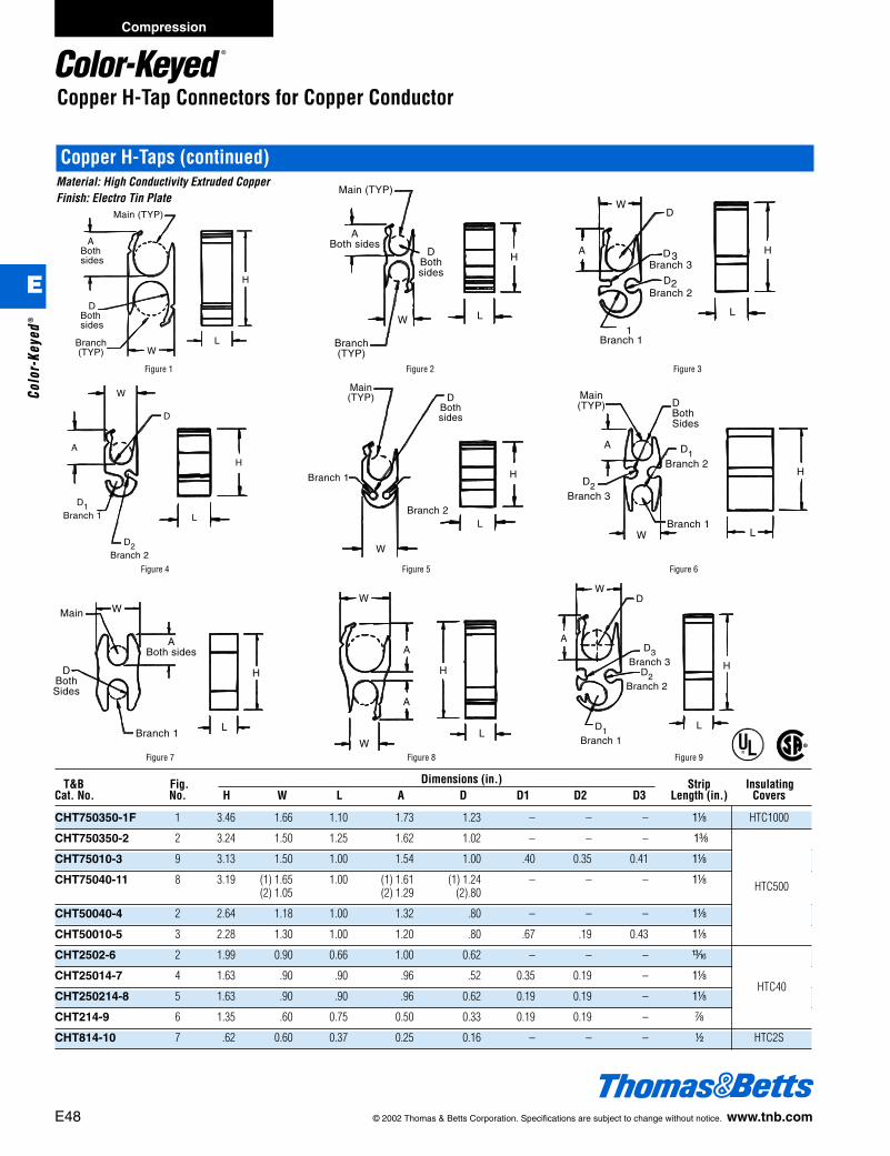
Copper H-Tap Connectors for Copper Conductor
Copper H-Taps (continued)Material: High Conductivity Extruded CopperFinish: Electro Tin Plate
®
®
Branch(TYP)
Main (TYP)
ABothsides
DBothsides
LW
H
Branch(TYP)
Main (TYP)
ABoth sides
W
DBothsides
H
L
W
H
L
A
D
Branch 11
D3
2Branch 2
Branch 3
D
Figure 1 Figure 2 Figure 3
D1Branch 1
D2Branch 2
H
L
A
W
D
L
DBothsides
Branch 1
W
Branch 2
H
Main(TYP)
D2Branch 3
WBranch 1
Main(TYP)
A
DBothSides
D1Branch 2
H
L
Figure 4 Figure 5 Figure 6
Main W
ABoth sides
DBothSides
Branch 1L
H
WL
W
A
A
H
D1Branch 1
A
WD
D2Branch 2
L
H
D3Branch 3
Figure 7 Figure 8 Figure 9
E48 © 2002 Thomas & Betts Corporation. Specifications are subject to change without notice. www.tnb.com
Compression
E
Colo
r-Ke
yed®
T&B Fig. Dimensions (in.) Strip InsulatingCat. No. No. H W L A D D1 D2 D3 Length (in.) Covers
CHT750350-1F 1 3.46 1.66 1.10 1.73 1.23 – – – 1a HTC1000
CHT750350-2 2 3.24 1.50 1.25 1.62 1.02 – – – 1c
CHT75010-3 9 3.13 1.50 1.00 1.54 1.00 .40 0.35 0.41 1a
CHT75040-11 8 3.19 (1) 1.65 1.00 (1) 1.61 (1) 1.24 – – – 1a(2) 1.05 (2) 1.29 (2).80
CHT50040-4 2 2.64 1.18 1.00 1.32 .80 – – – 1a
CHT50010-5 3 2.28 1.30 1.00 1.20 .80 .67 .19 0.43 1a
CHT2502-6 2 1.99 0.90 0.66 1.00 0.62 – – – m
CHT25014-7 4 1.63 .90 .90 .96 .52 0.35 0.19 – 1a
CHT250214-8 5 1.63 .90 .90 .96 0.62 0.19 0.19 – 1a
CHT214-9 6 1.35 .60 0.75 0.50 0.33 0.19 0.19 – g
CHT814-10 7 .62 0.60 0.37 0.25 0.16 – – – d HTC2S
HTC500
HTC40
412031.E01 CK 3/5 3/13/03 8:22 PM Page 48

© 2002 Thomas & Betts Corporation. Specifications are subject to change without notice. www.tnb.com E49
Compression
E
Color-Keyed®
Compression Taps for 600V, 90°C ApplicationsDie Code Cat. No.
Combinations TBM6- Hydraulic TBM12 TBM15ISide Color TBM6S TBM14M 12-Ton 15-Ton
Cat. No. Main Branch Tap Length (in.) Key TBM60RS 13100A Head Head
63105† 2-6 8-14 – f Orange 13474upper13477lower 15530 TBM12D-4 15530*
63110 4-6 4-6 – 1d Green 13470 15501A TBM12D-H 15001A*63118 2/0-2 8-14 – f Green 13470 15501A TBM12D-H 15501A*63125 2/0-2 1/0-6 – 1d Green 13470 15501A TBM12D-H 15501A*63140 4/0-2/0 2-10 – 1d Blue 13471 15502 TBM12D-H 15502*63148• 4/0-2/0 3/0-1 8-14 3 Blue – 15502 TBM12D-H 1550263160 500-4/0 4/0-2 2-6 2f Red – – – 1561263169 750-4/0 750-4/0 – 3 Black – – – 1562063170 1000-500 1000-1/0 – 6 Black – – – 1562063180 750-350 350-1/0 1-6 3 Black – – – 15620
* Use with adaptor Cat. No. 15500-TB† 63105 also installed by TBM5/TBM5S with 13455 die or TBM8/TBM8S with 13462 die.• 63148 – #1 CU or AL - wire bent double (hairpin)
For Smart Tool Installation63110, 63118, 63125 Use TBM8-750HG63140, 63148 Use TBM8-750BHTooling: Pg. E78-E102Die Selector Chart: Pg. E107-E111
H-type compression taps for combinations of aluminum to aluminum, aluminum to copper, and copper to copper stranded conductors with exclusive FILLERLOK tab design. Concentric and compact code strandings.
Material – High Conductivity Wrought Aluminum.®
®
Aluminum H-Tap Connectors for Aluminum/Copper Code Conductor (Up to 600V)
412031.E01 CK 3/5 3/13/03 8:22 PM Page 49
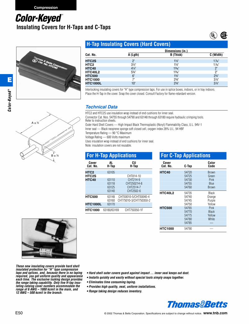
E50 © 2002 Thomas & Betts Corporation. Specifications are subject to change without notice. www.tnb.com
Insulating Covers for H-Taps and C-Taps
H-Tap Insulating Covers (Hard Covers)Dimensions (in.)
Cat. No. A (Lgth) B (Thick) C (Width)
HTC2S 2" 1a" 1k"HTC2 3d" 1a" 1k"HTC40 4b" 1l" 2"HTC40L2 5f" 1l" 2"HTC500 6" 1f" 2f"HTC1000 7" 2c" 3g"HTC1000L 10" 2c" 3g"
Interlocking insulating covers for “H” type compression taps. For use in splice boxes, indoors, or in tray indoors.Place the H-Tap in the cover. Snap the cover closed. Consult Factory for flame-retardant version.
Technical DataHTC2 and HTC2S use insulation wrap instead of end cushions for inner seal.Connector Cat. Nos. 54755 through 54790 and 63148 through 63180 require hydraulic crimping tools. Refer to instruction sheets.Outer Hard Shell Covers — High Impact Black Thermoplastic (Noryl) Flammability Class, U.L. 94V-1Inner seal — Black neoprene sponge soft closed cell, oxygen index 28% U.L. 94 HBFTemperature Rating — 90 °C MaximumVoltage Rating — 600 Volts maximumUses insulation wrap instead of end cushions for inner seal.Note: insulation covers are not reusable.
B+_ 1/8
A+_ 1/8A ± a
B ± a
®
®
For H-Tap ApplicationsCover AL CU
Cat. No. H-Tap H-Tap
HTC2 63105HTC2S CHT814-10HTC40 63110 CHT214-9
63118 CHT250214-863125 CHT2514-763140 CHT2502-6
HTC500 63148 CHT50010-5/CHT50040-463160 CHT75010-3/CHT750350-2
HTC1000L 63170
HTC1000 63180/63169 CHT750350-1F
For C-Tap ApplicationsCover Color
Cat. No. C-Tap Code
HTC40 54720 Brown54725 Green54730 Pink54755 Blue54760 Brown
HTC40L2 54735 Black54740 Orange54745 Purple54750 Yellow
HTC500 54765 Pink54770 Black54775 Yellow54780 White54785 —
HTC1000 54790 —
These new insulating covers provide hard shellinsulated protection for “H” type compressiontaps and splices, and, because there is no tapingrequired, you get uniform quality and appearanceeach time. The exclusive locking design providesthe range taking capability. Only five H-tap insu-lating catalog cover numbers accommodate therange of 6 AWG – 1000 kcmil in the main, and 12 AWG – 500 kcmil in the branch.
• Hard shell outer covers guard against impact … inner seal keeps out dust.• Installs quickly and easily without special tools simply snaps together.• Eliminates time consuming taping.• Provides high quality, neat, uniform installations.• Range taking design reduces inventory.
Compression
E
Colo
r-Ke
yed®
412031.E01 CK 3/5 3/13/03 8:22 PM Page 50

Wire Range Use to Insulate Dimensions (In.)Cat. No. Max. Min. AL H-Taps A B C “A” Dim. “B” Dim.
HT20C 2/0 6 63110/63115 4d" 1b" 1a" – –63125/63120
HT40C 4/0 6 63140 5T" 1u" 1i" – –63148
HT600C 500 MCM 2 63160 63169 6m" 2a" 1T" – –HT1000C 1000 MCM 250 MCM 63180 – – – [184.15MM] 2.330
to 500 MCM to 1/0 AWG 7.250 +.060HT1000C-L 1000 MCM 250 MCM 63170 – – – [263.40MM] 2.330
to 500 MCM to 250 MCM 10.374 +.060
© 2002 Thomas & Betts Corporation. Specifications are subject to change without notice. www.tnb.com E51
Insulating Covers for H-Taps and C-Taps
H-Tap Insulating Covers (Soft Cover)Cat. Wire Range Installs on “H” TapNo. Min. Max. Cat. No.
HT20C 6 2/0 63110 & 63125HT40C 6 4/0 63140 & 63148HT600C 2 500 MCM 63160 & 63169HT1000C 1/0 750 MCM 63180HT1000C-L 1/0 1000 MCM 63170
Technical DataRating: 90°C, 600V. Made of flame retardant, high impact polypropylene.Material: PolypropyleneColor: BlackVoltage Rating 600V max.Temperature: 90°C
B
A
C
(C) height, typicalboth halves
Easily and quickly insulates on H type compres-sion taps. Eliminates taping. Provided withthree positive locking latches and overlappingfringe for maximum cable insulation.
®
®
Compression
E
Color-Keyed®
412031.E01 CK 3/5 3/13/03 8:22 PM Page 51

Made of high conductivity copper, electro-tin-plated, these compression joints offer an idealmethod of pigtailing or tapping multiple con-ductors or for making a 2-way splice.Connectors and dies are colored for positivematching and compression.All-around compression assures high conduc-tivity, low resistance, and high pullout valueswhich exceed Underwriters’ Laboratories, Inc.requirements. These compression joints forma permanent installation, take a minimumamount of space, are easily insulated and givelowest installed cost.
A E
Wire Joints for Copper Conductor
®
®
Installing Tools
Connector Range Hand Tools
Circular Mil Area Cable Combination Dim. (in.) Color TBM25S/21E TBM8/BS TBM5/5S TBM6 & TBM6SCat. No. min. max. min. max. A E Code Die Cat. No. Die Cat. No. Die Cat. No. Upper Lower
54610 19,590 27,290 3 #12 sol or str 2 #10 w/1 #12 sol or str .407 .370 Blue Included 13475 1347754615 31,140 43,400 3 #10 sol or str 4 #10 sol or str .407 .430 Gray Included 13461 13454 13472 1347654620 49,530 65,560 3 #8 sol or str 1 #4 w/2 #10 sol or str .417 .475 Brown Included 1347454625-TB 66,040 87,130 4 #8 sol or str 1 #2 str w/2 #12 sol or str .479 .545 Green54630 83,480 99,990 2 #4 sol or str 2 #4 w/1 #10 sol or str .479 .585 Pink 13462 13455 13475 1347754635 99,060 124,220 6 #8 str 2 #4 w/2 #8 sol or str .762 .620 Black 1347454640 125,220 166,120 3 #4 sol or str 3 #4 w/2 #10 sol or str .762 .695 Orange54645-TB 166,960 193,630 4 #4 sol or str 2 #1 w/2 #10 sol or str .824 .770 Purple 13463 13456 1347554650 189,190 244,020 3 #2 str 2 #1/0 w/2 #8 str .887 .830 Yellow 13473 13476
Hand tools only.UL Listed E9809 - code strandedTooling: Pg. E78-E102Die Selector Chart: Pg. E107-E111
E52 © 2002 Thomas & Betts Corporation. Specifications are subject to change without notice. www.tnb.com
Compression
E
Colo
r-Ke
yed®
412031.E01 CK 3/5 3/13/03 8:22 PM Page 52

Cast Copper Bus Taps for Copper Conductor
Heavy Duty Bus Bar Taps - Straight Barrel Angle600V to 35KV ApplicationsMaterial: High Conductivity Cast Copper AlloyFinish: Electro Tin PlateContact Material: Be CuFinish: Silver
• For up to 1⁄2" thick bus bar 3" to 6" widths.• For code copper cable.• Clamps on – no drilling of bus bar.• Takes up less than 11⁄2" of bus bar space.• Convex shape of connector tongue exerts
great contact pressure on bus bar.• Installs with hydraulic tools and
hex crimp dies.
1-3/8 Approx.
A Approx.
“T” Dim.1/2 Nom. For All
Parts Listed(See Chart)
Bronze Palnut C
3/8-16 CopperPlated Steel
Bolts and NutsBrazed
BApprox.
Figure 1 C
1"
1-3/8 Approx.A Approx.
“T” Dim.1/2 Nom. For All
Parts Listed(See Chart)
Bronze Palnut
3/8-16 CopperPlated Steel
Bolts and NutsBrazed
BApprox.
Figure 2
T&B Wire Flex Fig. Busbar Dimensions (in.) DieCat. No. Code Flex No. Width A B C Code
251-31446-1 1 3 6a 2s 3d 66H251-31446-7 1/0 225/24 1 4 7a 2s 4d 66H251-31446-13 2 5 or 6 9a 2s 6c 66H
251-31446-82/0
1/0 1 4 7a 2s 4d 66H251-31446-14 275/24 2 5 or 6 9a 2s 6c 66H
251-31446-23 1 3 6a 2s 3d 66H251-31446-22 4/0 450/24 1 4 7a 2s 4d 66H251-31446-19 2 6 9a 2s 64/9 66H
251-31446-29250 4/0
1 3 5L 2s 3c 66H251-31446-30
kcmil 550/241 4 7a 2s 4d 66H
251-31446-31 1 5 or 6 9a 2s 6k 66H
251-31446-3350
1 3 6e 2l 3d 99H251-31446-9
kcmil1 4 7e 2l 4d 99H
251-31446-15 2 5 or 6 9e 2l 6c 99H
251-31446-4500 350
1 3 6e 2l 3d 99H251-31446-10
kcmil 925/241 4 7e 2l 4 d 99H
251-31446-16 2 5 or 6 9e 2l 6c 99H
251-31446-17600
2 5 or 6 9f 2f 6c 112Hkcmil
251-31446-21700
1 6 9f 2f 6k 112Hkcmil
251-31446-6750 500
1 3 6f 2f 3d 112H251-31446-12
kcmil 1325/242 4 7f 2f 4d 112H
251-31446-18 2 5 or 6 9f 2f 6c 112H
251-31446-36750
2 5 or 6 9f 2f 6k 112H1925/24
NOTES:Styles shown have cable tap on one portion of clamp assembly. Clamp assemblies with cable taps on both portions (top & bottom identical) are also available. These assemblies are identified by adding suffix “AD” to part numbers shown. Example: 251-31446-1AD
Only use hydraulic tools with hex crimp dies.Tooling: Pg. E78-E102Die Selector Chart: Pg. E107-E111
Double Cable – Use AD Suffix
© 2002 Thomas & Betts Corporation. Specifications are subject to change without notice. www.tnb.com E53
Compression
E
Color-Keyed®
412031.E01 CK 3/5 3/13/03 8:22 PM Page 53
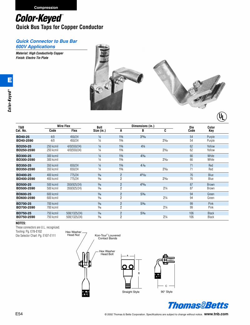
E54 © 2002 Thomas & Betts Corporation. Specifications are subject to change without notice. www.tnb.com
Compression
E
Colo
r-Ke
yed®
Quick Connector to Bus Bar600V ApplicationsMaterial: High Conductivity CopperFinish: Electro Tin Plate
T&B Wire Flex Bolt Dimensions (in.) Die ColorCat. No. Code Flex Size (in.) A B C Code Key
BD40-25 4/0 450/24 b 1c 3m 54 PurpleBD40-2590 4/0 450/24 b 1c 2q 54 Purple
BD250-25 250 kcmil 4/0(550/24) b 1c 4a 62 YellowBD250-2590 250 kcmil 4/0(550/24) b 1c 2q 62 Yellow
BD300-25 300 kcmil b 1c 4i 66 WhiteBD300-2590 300 kcmil b 1c 2q 66 White
BD350-25 350 kcmil 650/24 b 1c 4k 71 RedBD350-2590 350 kcmil 650/24 b 1c 2q 71 Red
BD400-25 400 kcmil 775/24 j 2 4y 76 BlueBD400-2590 400 kcmil 775/24 j 2 2q 76 Blue
BD500-25 500 kcmil 350(925/24) j 2 4m 87 BrownBD500-2590 500 kcmil 350(925/24) j 2 2b 87 Brown
BD600-25 600 kcmil j 2 5i 94 GreenBD600-2590 600 kcmil j 2 2b 94 Green
BD700-25 700 kcmil j 2 5i 99 PinkBD700-2590 700 kcmil j 2 2b 99 Pink
BD750-25 750 kcmil 500(1325/24) j 2 5i 106 BlackBD750-2590 750 kcmil 500(1325/24) j 2 2b 106 Black
NOTES:These connectors are U.L. recognized.Tooling: Pg. E78-E102Die Selector Chart: Pg. E107-E111
Hex WasherHead Nut
Hex WasherHead Bolt
Kon-Tour® LouveredContact Bands
Straight Style 90° Style
A
B
C
Quick Bus Taps for Copper Conductor
®
412031.E01 CK 3/5 3/13/03 8:22 PM Page 54

© 2002 Thomas & Betts Corporation. Specifications are subject to change without notice. www.tnb.com E55
Compression
E
Color-Keyed®
Female Disconnect Male Disconnect
B E
A
C
D
F
B E
A
C
Motor Pigtail Connectors
Motor Lead Disconnects
Thomas & Betts offers a complete lineof Motor Lead Disconnects for 600 voltand 5kv applications. Constructed ofhigh conductivity copper with tin-plat-ing, these disconnects achieve quick,reliable change out of electric motorswhile eliminating bolting, taping andloose connections.
The Motor Lead Disconnects cover thewire range from #16 through 4/0 AWGand meet or exceed the electrical andmechanical performance of boltedconnections. The female disconnectsare equipped with a beryllium copperinterface band to produce dependableconnections.
Features and Benefits• Quick connections–Eliminates nuts,
bolts and washers.• Reliable insulation–No more “miles” of
insulating tape. Simply slide on thereusable boot, keeping the totalassembly small enough to fit into tightmotor housings.
• Labor savings–Fast snap-togetherassembly.
• Quick disconnect–No knife-cutting ofmelted tape, therefore no risk of cut-ting wire insulation, less motor down-time, and installer exposure in hostileenvironments is minimized.
Motor Pigtail Connector – One Line to One Load (2 Wire)Cat. No. Dimensions (in.) Strip
Female Male Body Color Boot LengthDisconnect Disconnect Wire Size Size Code Insulation A B C D E F (in.)MD1614F-0 MD1614M-0 16-14 AWG 0 Blue MDBOOT-0 .25 .25 .63 .52 .25 .125 c"
MD1614F-1 MD1614M-1 16-14 AWG 1 Blue MDBOOT-1 .38 .38 .78 .75 .38 .250 c"
MD1210F-1 MD1210M-1 12-10 AWG 1 Yellow MDBOOT-1 .38 .38 .78 .75 .38 .250 c"
MD1210F-2 MD1210M-2 12-10 AWG 2 Yellow MDBOOT-2 .50 .50 .90 1.00 .50 .370 c"
MD8F-1 MD8M-1 8 AWG 1 Red MDBOOT-1 .38 .38 .82 .75 .38 .250 k"
MD8F-2 MD8M-2 8 AWG 2 Red MDBOOT-2 .50 .50 .95 1.00 .50 .370 k"
MD6F-1 MD6M-1 6 AWG 1 Blue MDBOOT-1 .38 .38 .88 .75 .38 .250 d"
MD6F-2 MD6M-2 6 AWG 2 Blue MDBOOT-2 .50 .50 1.02 1.00 .50 .370 d"
MD4F-2 MD4M-2 4 AWG 2 Gray MDBOOT-2 .50 .50 1.06 1.00 .50 .370 d"
MD2F-2 MD2M-2 2 AWG 2 Brown MDBOOT-2 .50 .50 1.09 1.00 .50 .370 w"
MD2F-3 MD2M-3 2 AWG 3 Brown MDBOOT-3 .88 .88 1.46 1.75 .88 .500 w"
MD1F-2 MD1M-2 1 AWG 2 Green MDBOOT-2 .50 .50 1.23 1.00 .50 .370 l"
MD1F-3 MD1M-3 1 AWG 3 Green MDBOOT-3 .88 .88 1.56 1.75 .88 .500 l"
MD10F-3 MD10M-3 1/0 AWG 3 Pink MDBOOT-3 .88 .88 1.56 1.75 .88 .500 l"
MD20F-3 MD20M-3 2/0 AWG 3 Black MDBOOT-3 .88 .88 1.59 1.75 .88 .500 e"
MD30F-3 MD30M-3 3/0 AWG 3 Orange MDBOOT-3 .88 .88 1.71 1.75 .88 .500 L"
MD40F-3 MD40M-3 4/0 AWG 3 Purple MDBOOT-3 .88 .88 1.81 1.75 .88 .500 f"
Tooling: Pg. E78-E102Die Selector Chart: Pg. E107-E111
412031.E01 CK 3/5 3/13/03 8:22 PM Page 55

E56 © 2002 Thomas & Betts Corporation. Specifications are subject to change without notice. www.tnb.com
Motor Pigtail Connectors
Motor Pigtail Connector – One Line to One Load (2 Wire) – (continued)WT112M
Installing ToolsCat. No. WT111M TBM5 TBM8 Hydraulic Tools &
Female Male WT2000 TBM25S TBM6, TBM6S, TBM60RS TBM5S TBM8S TBM50S Hand ToolDisconnect Disconnect ERG2002 TBM20S Upper Die Lower Die Die Set Die Set Die Code Color
MD1614F-0 MD1614M-0 X
MD1614F-1 MD1614M-1 X
MD1210F-1 MD1210M-1 X
MD1210F-2 MD1210M-2 X
MD8F-1 MD8M-1 X 13475 13477 13454 13461 21 Red
MD8F-2 MD8M-2 X 13475 13477 13454 13461 21 Red
MD6F-1 MD6M-1 X 13475 13477 13454 13461 24 Blue
MD6F-2 MD6M-2 X 13475 13477 13454 13461 24 Blue
MD4F-2 MD4M-2 X 13472 13476 13454 13461 29 Gray
MD2F-2 MD2M-2 X 13474 13477 13454 13461 33 Brown
MD2F-3 MD2M-3 X 13474 13477 13454 13461 33 Brown
MD1F-2 MD1M-2 13474 13477 13455 13462 37 Green
MD1F-3 MD1M-3 13474 13477 13455 13462 37 Green
MD10F-3 MD10M-3 13475 13477 13455 13462 42 Pink
MD20F-3 MD20M-3 13474 13477 13455 13462 45 Black
MD30F-3 MD30M-3 13474 13477 13455 13462 50 Orange
MD40F-3 MD40M-3 13475 13477 13456 13463 54 Purple
Specifications:Wire range: No. 16 to 4/0 AWGRating: 600V, 90°CMaterial: High conductivity copperPlating: TinInsulator: Thermoplastic ElastomerQuick, Easy Installation1. Choose appropriate Color-Keyed® disconnect for conductor size to be terminated. Note color of bands on disconnect barrel.2. Select proper installing die by matching die color to disconnect barrel color bands.3. Install die in T&B tool, insert stripped wire into barrel of disconnect and compress between color bands. Repeat for mating half.4. Snap the two halves together and slip on insulator over mated connection. Secure insulator with TY-RAP® cable ties provided with the insulators.
®
®
Material: High Conductivity CopperPlating: TinInsulator: Thermoplastic Elastomer
5KV Volt Version600 Volt VersionTooling: Pg. E78-E102Die Selector Chart: Pg. E107-E111
Compression
E
Colo
r-Ke
yed®
412031.E01 CK 3/5 3/13/03 8:22 PM Page 56
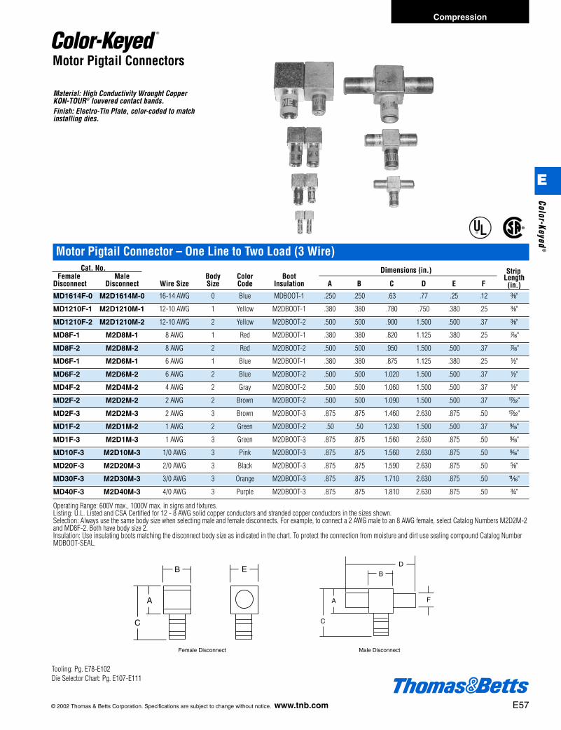
© 2002 Thomas & Betts Corporation. Specifications are subject to change without notice. www.tnb.com E57
Material: High Conductivity Wrought Copper KON-TOUR® louvered contact bands.Finish: Electro-Tin Plate, color-coded to match installing dies.
Motor Pigtail Connector – One Line to Two Load (3 Wire)Cat. No. Dimensions (in.) Strip
Female Male Body Color Boot LengthDisconnect Disconnect Wire Size Size Code Insulation A B C D E F (in.)MD1614F-0 M2D1614M-0 16-14 AWG 0 Blue MDBOOT-1 .250 .250 .63 .77 .25 .12 c"
MD1210F-1 M2D1210M-1 12-10 AWG 1 Yellow M2DBOOT-1 .380 .380 .780 .750 .380 .25 c"
MD1210F-2 M2D1210M-2 12-10 AWG 2 Yellow M2DBOOT-2 .500 .500 .900 1.500 .500 .37 c"
MD8F-1 M2D8M-1 8 AWG 1 Red M2DBOOT-1 .380 .380 .820 1.125 .380 .25 k"
MD8F-2 M2D8M-2 8 AWG 2 Red M2DBOOT-2 .500 .500 .950 1.500 .500 .37 k"
MD6F-1 M2D6M-1 6 AWG 1 Blue M2DBOOT-1 .380 .380 .875 1.125 .380 .25 d"
MD6F-2 M2D6M-2 6 AWG 2 Blue M2DBOOT-2 .500 .500 1.020 1.500 .500 .37 d"
MD4F-2 M2D4M-2 4 AWG 2 Gray M2DBOOT-2 .500 .500 1.060 1.500 .500 .37 d"
MD2F-2 M2D2M-2 2 AWG 2 Brown M2DBOOT-2 .500 .500 1.090 1.500 .500 .37 w"
MD2F-3 M2D2M-3 2 AWG 3 Brown M2DBOOT-3 .875 .875 1.460 2.630 .875 .50 w"
MD1F-2 M2D1M-2 1 AWG 2 Green M2DBOOT-2 .50 .50 1.230 1.500 .500 .37 l"
MD1F-3 M2D1M-3 1 AWG 3 Green M2DBOOT-3 .875 .875 1.560 2.630 .875 .50 l"
MD10F-3 M2D10M-3 1/0 AWG 3 Pink M2DBOOT-3 .875 .875 1.560 2.630 .875 .50 l"
MD20F-3 M2D20M-3 2/0 AWG 3 Black M2DBOOT-3 .875 .875 1.590 2.630 .875 .50 e"
MD30F-3 M2D30M-3 3/0 AWG 3 Orange M2DBOOT-3 .875 .875 1.710 2.630 .875 .50 L"
MD40F-3 M2D40M-3 4/0 AWG 3 Purple M2DBOOT-3 .875 .875 1.810 2.630 .875 .50 f"
Operating Range: 600V max., 1000V max. in signs and fixtures.Listing: U.L. Listed and CSA Certified for 12 - 8 AWG solid copper conductors and stranded copper conductors in the sizes shown.Selection: Always use the same body size when selecting male and female disconnects. For example, to connect a 2 AWG male to an 8 AWG female, select Catalog Numbers M2D2M-2and MD8F-2. Both have body size 2.Insulation: Use insulating boots matching the disconnect body size as indicated in the chart. To protect the connection from moisture and dirt use sealing compound Catalog NumberMDBOOT-SEAL.
Female Disconnect Male Disconnect
B E
A
C
D
F
B
A
C
Motor Pigtail Connectors
®®
Tooling: Pg. E78-E102Die Selector Chart: Pg. E107-E111
Compression
E
Color-Keyed®
412031.E01 CK 3/5 3/13/03 8:22 PM Page 57

E58 © 2002 Thomas & Betts Corporation. Specifications are subject to change without notice. www.tnb.com
Compression
E
Colo
r-Ke
yed®
Motor Pigtail Connector – One Line to Two Load (3 Wire) – (continued)WT112M
Installing ToolsCat. No. WT111M TBM5 TBM8
Female Male ERG 2002 TBM6, TBM6S, TBM60RS TBM5S TBM8S Hydraulic Tools Disconnect Disconnect WT2000 TBM25S Upper Die Lower Die Die Set Die Set Die Code Color
MD1210F-1 M2D1210M-1 X – – – – – – Yellow
MD1210F-2 M2D1210M-2 X – – – – – – Yellow
MD8F-1 M2D8M-1 X 13475 13477 13454 13461 21 Red
MD8F-2 M2D8M-2 X 13475 13477 13454 13461 21 Red
MD6F-1 M2D6M-1 X 13475 13477 13454 13461 24 Blue
MD6F-2 M2D6M-2 X 13475 13477 13454 13461 24 Blue
MD4F-2 M2D4M-2 X 13472 13476 13454 13461 29 Gray
MD2F-2 M2D2M-2 X 13474 13477 13454 13461 33 Brown
MD2F-3 M2D2M-3 X 13474 13477 13454 13461 33 Brown
MD1F-2 M2D1M-2 13474 13477 13455 13462 37 Green
MD1F-3 M2D1M-3 13474 13477 13455 13462 37 Green
MD10F-3 M2D10M-3 13475 13477 13455 13462 42 Pink
MD20F-3 M2D20M-3 13474 13477 13455 13462 45 Black
MD30F-3 M2D30M-3 13474 13477 13455 13462 50 Orange
MD40F-3 M2D40M-3 13475 13477 13456 13463 54 Purple
MD1614F-0 M2D1614M-0 X – – – – – Blue
Tooling: Pg. E78-E102Die Selector Chart: Pg. E107-E111
Motor Pigtail Connectors
412031.E01 CK 3/5 3/13/03 8:22 PM Page 58
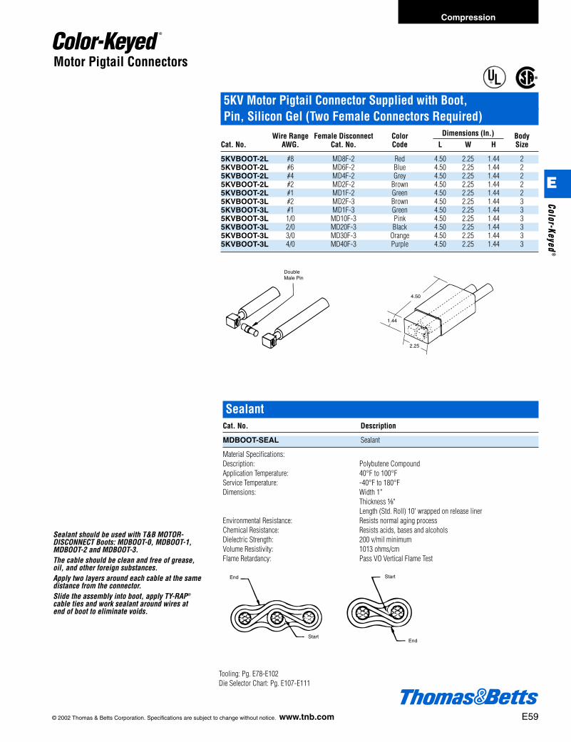
Motor Pigtail Connectors
5KV Motor Pigtail Connector Supplied with Boot, Pin, Silicon Gel (Two Female Connectors Required)
Wire Range Female Disconnect Color Dimensions (In.) BodyCat. No. AWG. Cat. No. Code L W H Size
5KVBOOT-2L #8 MD8F-2 Red 4.50 2.25 1.44 25KVBOOT-2L #6 MD6F-2 Blue 4.50 2.25 1.44 25KVBOOT-2L #4 MD4F-2 Grey 4.50 2.25 1.44 25KVBOOT-2L #2 MD2F-2 Brown 4.50 2.25 1.44 25KVBOOT-2L #1 MD1F-2 Green 4.50 2.25 1.44 25KVBOOT-3L #2 MD2F-3 Brown 4.50 2.25 1.44 35KVBOOT-3L #1 MD1F-3 Green 4.50 2.25 1.44 35KVBOOT-3L 1/0 MD10F-3 Pink 4.50 2.25 1.44 35KVBOOT-3L 2/0 MD20F-3 Black 4.50 2.25 1.44 35KVBOOT-3L 3/0 MD30F-3 Orange 4.50 2.25 1.44 35KVBOOT-3L 4/0 MD40F-3 Purple 4.50 2.25 1.44 3
®
®
DoubleMale Pin
4.50
2.25
1.44
Sealant should be used with T&B MOTOR-DISCONNECT Boots: MDBOOT-0, MDBOOT-1,MDBOOT-2 and MDBOOT-3.The cable should be clean and free of grease,oil, and other foreign substances.Apply two layers around each cable at the samedistance from the connector.Slide the assembly into boot, apply TY-RAP®
cable ties and work sealant around wires atend of boot to eliminate voids.
SealantCat. No. Description
MDBOOT-SEAL Sealant
Material Specifications:Description: Polybutene CompoundApplication Temperature: 40°F to 100°FService Temperature: -40°F to 180°FDimensions: Width 1"
Thickness a"Length (Std. Roll) 10' wrapped on release liner
Environmental Resistance: Resists normal aging processChemical Resistance: Resists acids, bases and alcoholsDielectric Strength: 200 v/mil minimumVolume Resistivity: 1013 ohms/cmFlame Retardancy: Pass VO Vertical Flame Test
End
Start
Start
End
Tooling: Pg. E78-E102Die Selector Chart: Pg. E107-E111
© 2002 Thomas & Betts Corporation. Specifications are subject to change without notice. www.tnb.com E59
Compression
E
Color-Keyed®
412031.E01 CK 3/5 3/13/03 8:22 PM Page 59

E60 © 2002 Thomas & Betts Corporation. Specifications are subject to change without notice. www.tnb.com
High-Amperage Quick Power Disconnects
Making connections for loads requiring high amperage has never been easier. Wehave designed this connector to be the fastest “off-load” connection possible, whilemaintaining the integrity of the system.Using the multi-contact approach, the design provides low insertion and extractionforces with low resistance and temperature rise. This unique design allows for mul-tiple connections and disconnection without the performance characteristicschanging or deteriorating.
Unique Construction
Material used in the design is 99.9% conductive copper, silver plated. The contactdesign is a louvered band of beryllium copper. All the raised edges of the louveredband are deflected, producing a multitude of high-force contact points, Each con-tact point is typically in the force range of 8,000 to 10,000 psi. High currents,caused by short circuits or sudden surges, tend to make the contact interface evenmore efficient by increasing the contact pressure.
Cat. No. DieMale Female Conductor Code
272-32175M 272-32175F 777 MCM 115Future Design 646 MCMFuture Design 535 MCMFuture Design 444MCM
Tooling: Pg. E78-E102Die Selector Chart: Pg. E107-E111
Locking Clip
Multi-Lam Contact
1f" 1
ø y"
ø 1d"
8k"
Compression
E
Colo
r-Ke
yed®
412031.E01 CK 3/5 3/13/03 8:22 PM Page 60

© 2002 Thomas & Betts Corporation. Specifications are subject to change without notice. www.tnb.com E61
T&B Method Traction Motor Disconnect Lugs for Diesel-Electric Locomotives
Cable Dimensions (in.) E Bolt Size (in.) DieCat. No. Size A B C D Approx. (in.) F G H Code
MD37 37/24 2k 1f x q c c j g 26MDD61 61/24 2k 1f x q c c j g 26MD 105 105/24 2e 1f x q k c j g 33MD 105 91/24 2e 1f x q k c j g 33MD 125 125/24 2e 1f x q k c j g 33MD 150 150/24 2n 1g x .203 e k j g 45MD 175 175/24 2n 1g x .203 e k j g 45MD 225 225/24 3 1g L .203 z k j g 60MD 275 275/24 3 1g L .203 z k j g 60MD 325 325/24 3 1g L .203 z k j g 60MD 375 375/24 3a 2 A .203 z k j g 60MD 450 450/24 3a 2 A .203 z k j g 60MD 550 550/24 3i 1g n .203 1 k j g 76MD 650 650/24 3i 1g n .203 1 k j g 76MD 775 775/24 3i 1g n .203 1 k j g 76MD 925 925/24 3f 2h 1a .375 1q k c 1 87MD 1100 1100/24 3f 2h 1X .375 1c k c 1 107MD 1325 1325/24 3A 2p 1q .375 1f k c 1 107MD 1600 1600/24 3f 2h 1X .375 1c k c 1 107MD 1925 1925/24 4h 2p 1X .375 1d k c 1 115MD 2300 2300/24 4c 2a 1x .375 1y k c 1 130
Note: Some parts may not be current on the system. Contact Tech Services for information.Tooling: Pg. E78-E102Die Selector Chart: Pg. E107-E111
Copper Traction Motor Disconnect Lugs for Diesel-Electric Locomotives
G
CE
H FA
B
D
g l
k
$
± Cat. No. MD 1925 Supplied WithElongated Bolt Hole.
Compression
E
Color-Keyed®
412031.E01 CK 3/5 3/13/03 8:22 PM Page 61
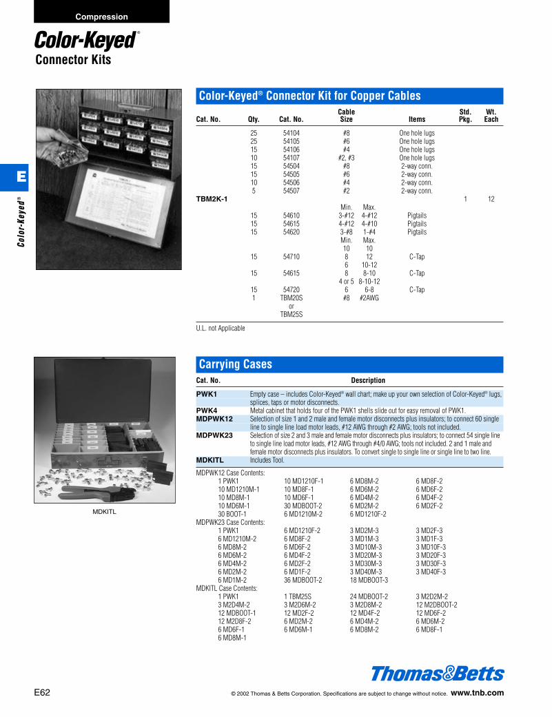
E62 © 2002 Thomas & Betts Corporation. Specifications are subject to change without notice. www.tnb.com
Compression
E
Colo
r-Ke
yed®
Connector Kits
Color-Keyed® Connector Kit for Copper CablesCable Std. Wt.
Cat. No. Qty. Cat. No. Size Items Pkg. Each
25 54104 #8 One hole lugs25 54105 #6 One hole lugs15 54106 #4 One hole lugs10 54107 #2, #3 One hole lugs15 54504 #8 2-way conn.15 54505 #6 2-way conn.10 54506 #4 2-way conn.5 54507 #2 2-way conn.
TBM2K-1 1 12Min. Max.
15 54610 3-#12 4-#12 Pigtails15 54615 4-#12 4-#10 Pigtails15 54620 3-#8 1-#4 Pigtails
Min. Max.10 10
15 54710 8 12 C-Tap6 10-12
15 54615 8 8-10 C-Tap4 or 5 8-10-12
15 54720 6 6-8 C-Tap1 TBM20S #8 #2AWG
orTBM25S
U.L. not Applicable
Carrying CasesCat. No. Description
PWK1 Empty case – includes Color-Keyed® wall chart; make up your own selection of Color-Keyed® lugs,splices, taps or motor disconnects.
PWK4 Metal cabinet that holds four of the PWK1 shells slide out for easy removal of PWK1.MDPWK12 Selection of size 1 and 2 male and female motor disconnects plus insulators; to connect 60 single
line to single line load motor leads, #12 AWG through #2 AWG; tools not included.MDPWK23 Selection of size 2 and 3 male and female motor disconnects plus insulators; to connect 54 single line
to single line load motor leads, #12 AWG through #4/0 AWG; tools not included. 2 and 1 male andfemale motor disconnects plus insulators. To convert single to single line or single line to two line.
MDKITL Includes Tool.
MDPWK12 Case Contents:1 PWK1 10 MD1210F-1 6 MD8M-2 6 MD8F-210 MD1210M-1 10 MD8F-1 6 MD6M-2 6 MD6F-210 MD8M-1 10 MD6F-1 6 MD4M-2 6 MD4F-210 MD6M-1 30 MDBOOT-2 6 MD2M-2 6 MD2F-230 BOOT-1 6 MD1210M-2 6 MD1210F-2
MDPWK23 Case Contents:1 PWK1 6 MD1210F-2 3 MD2M-3 3 MD2F-36 MD1210M-2 6 MD8F-2 3 MD1M-3 3 MD1F-36 MD8M-2 6 MD6F-2 3 MD10M-3 3 MD10F-36 MD6M-2 6 MD4F-2 3 MD20M-3 3 MD20F-36 MD4M-2 6 MD2F-2 3 MD30M-3 3 MD30F-36 MD2M-2 6 MD1F-2 3 MD40M-3 3 MD40F-36 MD1M-2 36 MDBOOT-2 18 MDBOOT-3
MDKITL Case Contents:1 PWK1 1 TBM25S 24 MDBOOT-2 3 M2D2M-23 M2D4M-2 3 M2D6M-2 3 M2D8M-2 12 M2DBOOT-212 MDBOOT-1 12 MD2F-2 12 MD4F-2 12 MD6F-212 M2D8F-2 6 MD2M-2 6 MD4M-2 6 MD6M-26 MD6F-1 6 MD6M-1 6 MD8M-2 6 MD8F-16 MD8M-1
MDKITL
412031.E01 CK 3/5 3/13/03 8:22 PM Page 62

© 2002 Thomas & Betts Corporation. Specifications are subject to change without notice. www.tnb.com E63
Compression
E
Color-Keyed®
The Copper Colloidal Surface Treatment That Protects, Lubricates and Enhances ConductivityBetween All Electrical ConnectionsGood connections are one of the most important aspects of electrical work. Mechanics know how much down-time is causedwhen fluids or oils leak into the raceway system or looking for a weak link in a ground system caused by a high resistance con-nection. Mechanics also know how much time is spent keeping contacts, switches, lugs and other connectors clean or replac-ing parts because of “green scourge” build-up. Thomas & Betts has the solution to improve connections made in thousands ofelectrical and raceway installations made each day by electricians everywhere.Kopr-Shield® compound is a unique homogenized blend of pure, polished colloidal copper, rust and corrosion inhibitors thatsimultaneously protects, lubricates and enhances the conductivity of the mating surfaces to which it is applied. Extremely
adhesive, Kopr-Shield® compound flows smoothly into uneven contours and voids,making application easy, protection and lubrication complete and positive. A sta-ble compound, it will not settle-out, thin, thicken, harden, or dry out under the mostsevere environmental conditions.Kopr-Shield® Compound has excellent temperature characteristics – brushed on at–50F to 250F (other compounds either turn solid or run like water at theseextremes). Even at 1800F, Kopr-Shield® remains intact for short terms.Kopr-Shield® Compound may be used to advantage in all electrical installations.When the environment is hostile to good electrical and mechanical connections,Kopr-Shield® Compound is a must!Use Kopr-Shield® Compound for Battery Lugs and Cables.
• Prevention of “Green Scourge” corrosion.• Reduction of resistance.• Ease of terminal installation and removal.Use Kopr-Shield® Compound for Raceways.
• Lubrication – Ease of assembly and disassembly.• Grounding Continuity Improved – Exceeds code requirements.
Use Kopr-Shield® Compound for Fuse Clips.
• Even Heat Distribution – Elimination of hot spots.• Oxidation Prevention – Prevents carbon path formation.• Lubrication – Easy installation and removal of fuses.Use Kopr-Shield® Compound for Wiping Contacts, Drum Switches and Slip Rings.
• Prevention of galling, burning, pitting and discoloration.• Suppression of arching and dissipation of coronas.• Lubrication for ease of operation.
ALUMA-SHIELD Aluminum Joint CompoundCat. No. Contains Description
21059 Squeeze Bottle Pt. For aluminum cable connections; contains fine zinc particles which breakAP8 8 oz. Brush Cap Can through oxide film on cable strands upon compression of connection; assures
a low resistance contact and seals out air and moisture.M53 50 Gallon Drum
Note: U.L. Listed only for use on electrical cables in cable connector assemblies, or on bus bars rated for NEC applica-tions up to 8 KV and 90°C.
®
®
Kopr-Shield®
Cat. No. Description Std. Pkg. Wt. Lbs./C
201-31879 1d oz. Container with brush 96 11.46201-31879-1 4 oz. Container with brush 24 38.54CP8-TB 8 oz. Container with brush 12 64.58CP16 16 oz. Container with brush 12 120.83CP128 1 Gallon Can 4 952.00
Connectors for Aluminum/Copper Code Conductor
412031.E01 CK 3/5 3/13/03 8:22 PM Page 63

E64 © 2002 Thomas & Betts Corporation. Specifications are subject to change without notice. www.tnb.com
Compression
E
Colo
r-Ke
yed®
Connectors for Aluminum/Copper Code Conductor
Belleville Compression Washers Plus Flat WasherDimensions (in.)
Flat Washer Belleville WasherCat. No. Bolt Sizes (in.) A B C D
60800B b f .067 L .05560801B j g .074 m .06560802B c 1 .083 n .07560803B d 1b .109 m .095
Washer OnlyDimensions (in.)
Flat Washer Belleville WasherCat. No. Bolt Sizes (in.) A B C D
60800 b – – L .05560801 j – – m .06560802 c – – n .07560803 d – – m .09560804 e – – 1d .110
Note: Ordering quantity must be in unit quantities and multiples thereof.The Bellville washer should be installed with a larger flat washer to spread the high stresses of the spring washer edgesover a large area of the lug and/or bus bar.
Dragon Tooth® Transition WashersBolt
Cat No. Size (in.) Torque in lbs.
DTW14 b 50-80DTW516 j 125-160DTW38 c 160-240DTW12 d 390-540DTW58 e 540-730
When bolting aluminum lugs and connectors tobus bars with steel or brass hardware, the rec-ommended practice to ensure a tight connec-tion is to use a Bellville spring washer on top ofa flat washer under the bolt head or nut. Forheavy duty service where the heat rise isexpected to exceed 30°C above ambient, thisprocedure maintains constant pressure as theconnector metals expand and contract withtemperature changes.
Belleville Spring WasherMaterial: Hardened SteelFinish: Tin PlateColor: YellowFlat Washer
Material: SteelFinish: TinChromate PlateColor: Yellow
Dragon Tooth® transition washers let you con-nect copper-to-aluminum, copper-to-copper, oraluminum-to-aluminum components quicklyand dependably.• Toothed surface penetrates aluminum and
copper oxides.• Eliminates need for:
1) grinding aluminum surfaces2) applying compounds3) spring-typed washers
• Lower installed cost.
Steelor Copper Stud
Compression Washer
Nut
Tin or Cadmium Plated Mild Steel
Flat Washer
Aluminum LugTin Plated
412031.E01 CK 3/5 3/13/03 8:22 PM Page 64
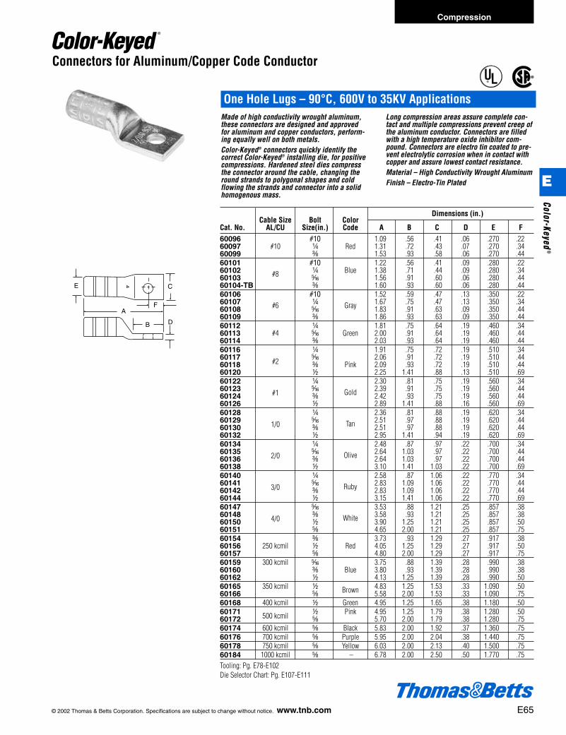
© 2002 Thomas & Betts Corporation. Specifications are subject to change without notice. www.tnb.com E65
Compression
E
Color-Keyed®
E
D
C
A
B
F
Connectors for Aluminum/Copper Code Conductor
One Hole Lugs – 90°C, 600V to 35KV ApplicationsMade of high conductivity wrought aluminum,these connectors are designed and approvedfor aluminum and copper conductors, perform-ing equally well on both metals.Color-Keyed® connectors quickly identify thecorrect Color-Keyed® installing die, for positivecompressions. Hardened steel dies compressthe connector around the cable, changing theround strands to polygonal shapes and coldflowing the strands and connector into a solidhomogenous mass.
Long compression areas assure complete con-tact and multiple compressions prevent creep ofthe aluminum conductor. Connectors are filledwith a high temperature oxide inhibitor com-pound. Connectors are electro tin coated to pre-vent electrolytic corrosion when in contact withcopper and assure lowest contact resistance.Material – High Conductivity Wrought AluminumFinish – Electro-Tin Plated
®
®
Cable Size Bolt ColorDimensions (in.)
Cat. No. AL/CU Size(in.) Code A B C D E F60096 #10 1.09 .56 .41 .06 .270 .2260097 #10 b Red 1.31 .72 .43 .07 .270 .3460099 c 1.53 .93 .58 .06 .270 .4460101 #10 1.22 .56 .41 .09 .280 .2260102 #8 b Blue 1.38 .71 .44 .09 .280 .3460103 j 1.56 .91 .60 .06 .280 .4460104-TB c 1.60 .93 .60 .06 .280 .4460106 #10 1.52 .59 .47 .13 .350 .2260107 #6 b 1.67 .75 .47 .13 .350 .3460108 j Gray 1.83 .91 .63 .09 .350 .4460109 c 1.86 .93 .63 .09 .350 .4460112 b 1.81 .75 .64 .19 .460 .3460113 #4 j Green 2.00 .91 .64 .19 .460 .4460114 c 2.03 .93 .64 .19 .460 .4460116 b 1.91 .75 .72 .19 .510 .3460117 #2 j 2.06 .91 .72 .19 .510 .4460118 c Pink 2.09 .93 .72 .19 .510 .4460120 d 2.25 1.41 .88 .13 .510 .6960122 b 2.30 .81 .75 .19 .560 .3460123 #1 j 2.39 .91 .75 .19 .560 .4460124 c Gold 2.42 .93 .75 .19 .560 .4460126 d 2.89 1.41 .88 .16 .560 .6960128 b 2.36 .81 .88 .19 .620 .3460129 1/0 j 2.51 .97 .88 .19 .620 .4460130 c Tan 2.51 .97 .88 .19 .620 .4460132 d 2.95 1.41 .94 .19 .620 .6960134 b 2.48 .87 .97 .22 .700 .3460135 2/0 j 2.64 1.03 .97 .22 .700 .4460136 c Olive 2.64 1.03 .97 .22 .700 .4460138 d 3.10 1.41 1.03 .22 .700 .6960140 b 2.58 .87 1.06 .22 .770 .3460141 3/0 j 2.83 1.09 1.06 .22 .770 .4460142 c Ruby 2.83 1.09 1.06 .22 .770 .4460144 d 3.15 1.41 1.06 .22 .770 .6960147 j 3.53 .88 1.21 .25 .857 .3860148 4/0 c 3.58 .93 1.21 .25 .857 .3860150 d White 3.90 1.25 1.21 .25 .857 .5060151 e 4.65 2.00 1.21 .25 .857 .7560154 c 3.73 .93 1.29 .27 .917 .3860156 250 kcmil d Red 4.05 1.25 1.29 .27 .917 .5060157 e 4.80 2.00 1.29 .27 .917 .7560159 300 kcmil j 3.75 .88 1.39 .28 .990 .3860160 c Blue 3.80 .93 1.39 .28 .990 .3860162 d 4.13 1.25 1.39 .28 .990 .5060165 350 kcmil d 4.83 1.25 1.53 .33 1.090 .5060166 e Brown 5.58 2.00 1.53 .33 1.090 .7560168 400 kcmil d Green 4.95 1.25 1.65 .38 1.180 .5060171 500 kcmil d Pink 4.95 1.25 1.79 .38 1.280 .5060172 e 5.70 2.00 1.79 .38 1.280 .7560174 600 kcmil e Black 5.83 2.00 1.92 .37 1.360 .7560176 700 kcmil e Purple 5.95 2.00 2.04 .38 1.440 .7560178 750 kcmil e Yellow 6.03 2.00 2.13 .40 1.500 .7560184 1000 kcmil e – 6.78 2.00 2.50 .50 1.770 .75Tooling: Pg. E78-E102Die Selector Chart: Pg. E107-E111
412031.E01 CK 3/5 3/13/03 8:22 PM Page 65
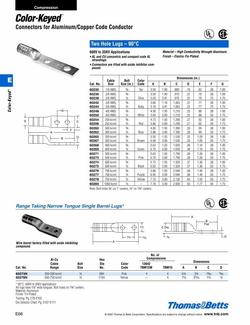
E66 © 2002 Thomas & Betts Corporation. Specifications are subject to change without notice. www.tnb.com
Compression
E
Colo
r-Ke
yed®
Connectors for Aluminum/Copper Code Conductor
Two Hole Lugs – 90°C
Dimensions (in.)Cable Bolt Color
Cat. No. Size Size (in.) Code A B C D E F G
60230 1/0 AWG c Tan 3.50 1.90 .880 .19 .62 .38 1.0060236 2/0 AWG c 3.50 1.90 .970 .22 .70 .38 1.0060238 2/0 AWG d Olive 5.03 3.41 .970 .22 .70 .75 1.7560242 3/0 AWG c 3.66 1.18 1.063 .22 .77 .38 1.0060244 3/0 AWG d Ruby 5.16 3.41 1.063 .22 .77 .75 1.7560248 4/0 AWG c 4.58 1.93 1.210 .25 .86 .38 1.0060250 4/0 AWG d White 5.65 3.00 1.210 .25 .86 .50 1.7560254 250 kcmil c 4.73 1.93 1.290 .27 .92 .38 1.0060256 250 kcmil d Red 5.80 3.00 1.290 .27 .92 .50 1.7560260 300 kcmil c 4.80 1.93 1.390 .28 .99 .38 1.0060262 300 kcmil d Blue 5.88 3.00 1.390 .28 .99 .50 1.7560265 350 kcmil c 5.50 1.93 1.530 .33 1.09 .38 1.0060267 350 kcmil d Brown 6.58 3.00 1.530 .33 1.09 .50 1.7560268 400 kcmil c 5.63 1.93 1.650 .38 1.18 .38 1.0060269 400 kcmil d Green 6.70 3.00 1.650 .38 1.18 .50 1.7560271 500 kcmil c 5.63 1.93 1.790 .38 1.28 .38 1.0060273 500 kcmil d Pink 6.70 3.00 1.790 .38 1.28 .50 1.7560274 600 kcmil c 5.75 1.93 1.920 .37 1.36 .38 1.0060275 600 kcmil d Black 6.83 3.00 1.920 .37 1.36 .50 1.7560276 700 kcmil c 5.88 1.93 2.040 .38 1.44 .38 1.0060277 700 kcmil d Purple 6.95 3.00 2.040 .38 1.44 .50 1.7560278 750 kcmil d Yellow 7.15 3.00 2.130 .40 1.50 .50 1.7560284 1000 kcmil d – 7.78 3.00 2.500 .50 1.77 .50 1.75Note: Bolt holes c" on 1" centers, d" on 1f" centers.
E
D
C
A
B
F
G
600V to 35KV Applications• AL and CU concentric and compact code AL
strandings.• Connectors are filled with oxide inhibitor com-
pound.
Material – High Conductivity Wrought Aluminum.Finish – Electro-Tin Plated.
®
®
Range Taking Narrow Tongue Single Barrel Lugs*
No. ofAl-Cu Hex Compressions
Cable Bolt Die Color 13642Dimensions
Cat. No. Range Size No. Code TBM12M TBM15 A B C D
60273N 350-500 kcmil d 99H Pink 4 4 6g 3a 1s u60278N 500-750 kcmil d 115H Yellow — 4 7a 3L 1d d
* 90°C, 600V to 35KV applicationsAll lugs have 1d" wide tongues. Bolt holes on 1f" centers.Material: AluminumFinish: Tin PlatedTooling: Pg. E78-E102Die Selector Chart: Pg. E107-E111
Wire barrel factory filled with oxide inhibitingcompound.
®
®
1d
y1f
A
D
A
BFlat
j
C Dia.
412031.E01 CK 3/5 3/13/03 8:22 PM Page 66
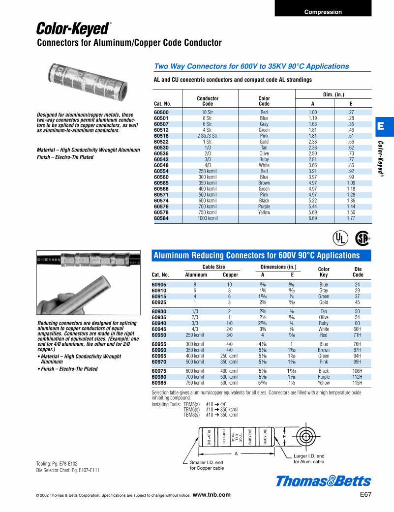
© 2002 Thomas & Betts Corporation. Specifications are subject to change without notice. www.tnb.com E67
Compression
E
Color-Keyed®
Reducing connectors are designed for splicingaluminum to copper conductors of equalampacities. Connectors are made in the rightcombination of equivalent sizes. (Example: oneend for 4/0 aluminum, the other end for 2/0copper.)• Material – High Conductivity Wrought
Aluminum• Finish – Electro-TIn Plated
®
®
Smaller I.D. end for Copper cable
Larger I.D. end for Alum. cable
RU
BY
DIE
RU
BY
DIE
RU
BY
DIE
RU
BY
DIE
T&
B3/
0 A
L
1/0 CU
A
E
Aluminum Reducing Connectors for 600V 90°C ApplicationsCable Size Dimensions (in.) Color Die
Cat. No. Aluminum Copper A E Key Code
60905 8 10 m s Blue 2460910 6 8 1e X Gray 2960915 4 6 1m k Green 3760925 1 3 2c w Gold 45
60930 1/0 2 2c e Tan 5060935 2/0 1 2d L Olive 5460940 3/0 1/0 2m f Ruby 6060945 4/0 2/0 3f g White 66H60950 250 kcmil 3/0 4 n Red 71H
60955 300 kcmil 4/0 4h 1 Blue 76H60960 350 kcmil 4/0 5h 1p Brown 87H60965 400 kcmil 250 kcmil 5h 1r Green 94H60970 500 kcmil 350 kcmil 5h 1j Pink 99H
60975 600 kcmil 400 kcmil 5j 1X Black 106H60980 700 kcmil 500 kcmil 5l 1k Purple 112H60985 750 kcmil 500 kcmil 5m 1d Yellow 115H
Selection table gives aluminum/copper equivalents for all sizes. Connectors are filled with a high temperature oxideinhibiting compound.Installing Tools: TBM5(s) #10 ➔ 4/0
TBM6(s) #10 ➔ 350 kcmilTBM8(s) #10 ➔ 350 kcmil
Conductor ColorDim. (in.)
Cat. No. Code Code A E
60500 10 Str. Red 1.00 .2760501 8 Str. Blue 1.19 .2860507 6 Str. Gray 1.63 .3560512 4 Str. Green 1.81 .4660516 2 Str./3 Str. Pink 1.81 .5160522 1 Str. Gold 2.38 .5660530 1/0 Tan 2.38 .6260536 2/0 Olive 2.50 .7060542 3/0 Ruby 2.81 .7760548 4/0 White 3.66 .8660554 250 kcmil Red 3.91 .9260560 300 kcmil Blue 3.97 .9960565 350 kcmil Brown 4.97 1.0960568 400 kcmil Green 4.97 1.1860571 500 kcmil Pink 4.97 1.2860574 600 kcmil Black 5.22 1.3660576 700 kcmil Purple 5.44 1.4460578 750 kcmil Yellow 5.69 1.5060584 1000 kcmil 6.69 1.77
Connectors for Aluminum/Copper Code Conductor
Designed for aluminum/copper metals, thesetwo-way connectors permit aluminum conduc-tors to be spliced to copper conductors, as wellas aluminum-to-aluminum conductors.
Two Way Connectors for 600V to 35KV 90°C Applications
AL and CU concentric conductors and compact code AL strandings
Material – High Conductivity Wrought AluminumFinish – Electro-Tin Plated
Tooling: Pg. E78-E102Die Selector Chart: Pg. E107-E111
412031.E01 CK 3/5 3/13/03 8:22 PM Page 67
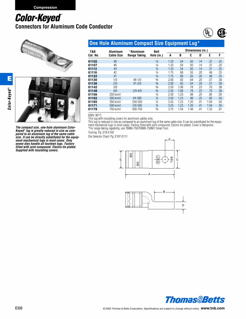
E68 © 2002 Thomas & Betts Corporation. Specifications are subject to change without notice. www.tnb.com
Connectors for Aluminum Code Conductor
The compact size, one-hole aluminum Color-Keyed® lug is greatly reduced in size as com-pared to an aluminum lug of the same cablesize. It can be directly substituted for the equip-ment mechanical lugs in most cases. Onlyseven dies handle all fourteen lugs. Factoryfilled with joint compound. Electro-tin plated.Supplied with insulating covers.
®
®
A
B
F
C
D
DIE
DIE
EU
SA
L
T&
B
One Hole Aluminum Compact Size Equipment Lug*T&B Aluminum *Aluminum Bolt Dimensions (in.)
Cat. No. Cable Size Range Taking Hole (in.) A B C D E F
61102 #8 b 1.33 .54 .50 .14 .37 .2561107 #6 b 1.33 .54 .50 .14 .37 .2561112 #4 b 1.33 .54 .50 .14 .37 .2561116 #2 b 1.75 .68 .55 .20 .48 .2561122 #1 b 1.75 .68 .55 .20 .48 .2561130 1/0 #8-1/0 c 2.00 .83 .64 .20 .57 .3861136 2/0 #1-2/0 c 2.00 .83 .64 .20 .57 .3861142 3/0 c 2.50 1.08 .78 .23 .70 .3861148 4/0 2/0-4/0 c 2.50 1.08 .78 .23 .70 .3861156 250 kcmil d 2.50 1.23 .98 .25 .85 .5061162 300 kcmil #4-300 d 2.50 1.23 .98 .25 .85 .5061165 350 kcmil 250-350 d 3.25 1.23 1.20 .41 1.04 .5661171 500 kcmil 2/0-500 d 3.25 1.23 1.20 .41 1.04 .5661178 750 kcmil 500-750 e 3.75 1.54 1.49 .41 1.33 .81
600V, 90°CThis lug with insulating covers for aluminum cables only.This lug is reduced in size as compared to an aluminum lug of the same cable size. It can be substituted for the equip-ment mechanical lugs in most cases. Factory filled with joint compound. Electro-tin plated. Cover is Neoprene.*For range taking capability, use TBM8-750/TBM8-750M1 Smart Tool.Tooling: Pg. E78-E102Die Selector Chart: Pg. E107-E111
Compression
E
Colo
r-Ke
yed®
412031.E01 CK 3/5 3/13/03 8:22 PM Page 68
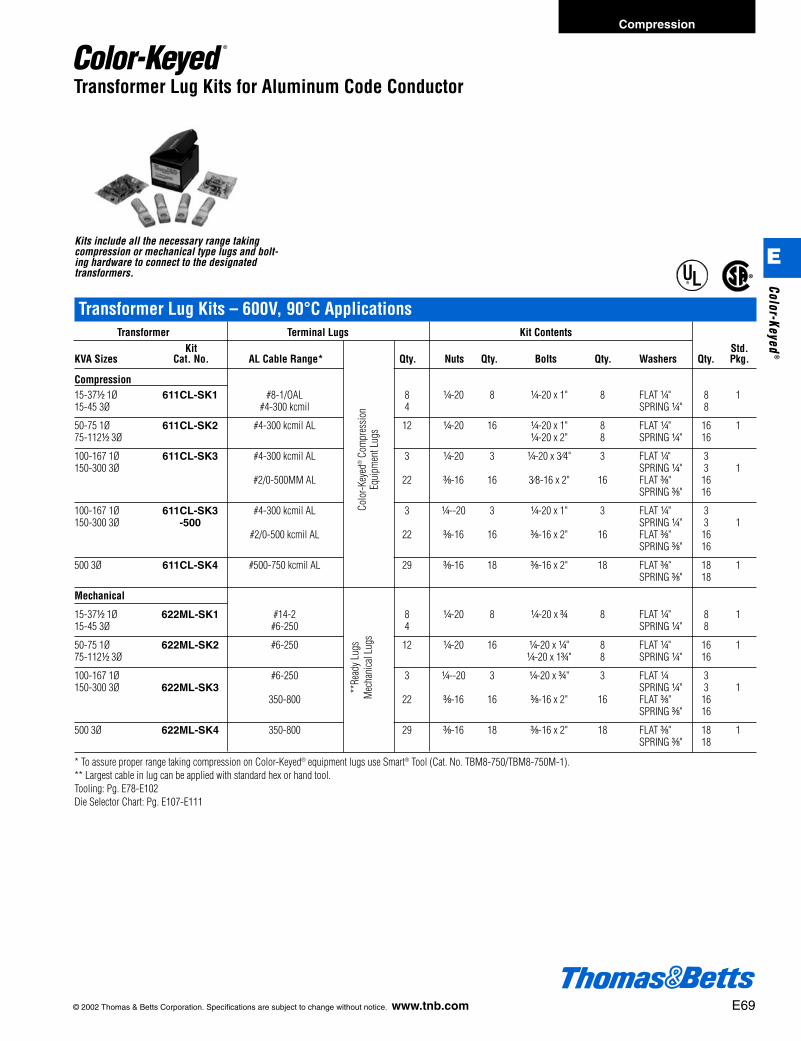
© 2002 Thomas & Betts Corporation. Specifications are subject to change without notice. www.tnb.com E69
Transformer Lug Kits – 600V, 90°C ApplicationsTransformer Terminal Lugs Kit Contents
Kit Std.KVA Sizes Cat. No. AL Cable Range* Qty. Nuts Qty. Bolts Qty. Washers Qty. Pkg.
Compression15-37d 1Ø 611CL-SK1 #8-1/OAL 8 b-20 8 b-20 x 1" 8 FLAT b" 8 115-45 3Ø #4-300 kcmil 4 SPRING b" 8
50-75 1Ø 611CL-SK2 #4-300 kcmil AL 12 b-20 16 b-20 x 1" 8 FLAT b" 16 175-112d 3Ø b-20 x 2" 8 SPRING b" 16
100-167 1Ø 611CL-SK3 #4-300 kcmil AL 3 b-20 3 b-20 x 3⁄4" 3 FLAT b" 3150-300 3Ø SPRING b" 3 1
#2/0-500MM AL 22 c-16 16 3⁄8-16 x 2" 16 FLAT c" 16SPRING c" 16
100-167 1Ø 611CL-SK3 #4-300 kcmil AL 3 b--20 3 b-20 x 1" 3 FLAT b" 3150-300 3Ø -500 SPRING b" 3 1
#2/0-500 kcmil AL 22 c-16 16 c-16 x 2" 16 FLAT c" 16SPRING c" 16
500 3Ø 611CL-SK4 #500-750 kcmil AL 29 c-16 18 c-16 x 2" 18 FLAT c" 18 1SPRING c" 18
Mechanical
15-37d 1Ø 622ML-SK1 #14-2 8 b-20 8 b-20 x f 8 FLAT b" 8 115-45 3Ø #6-250 4 SPRING b" 8
50-75 1Ø 622ML-SK2 #6-250 12 b-20 16 b-20 x b" 8 FLAT b" 16 175-112d 3Ø b-20 x 1f" 8 SPRING b" 16
100-167 1Ø #6-250 3 b--20 3 b-20 x f" 3 FLAT b 3150-300 3Ø 622ML-SK3 SPRING b" 3 1
350-800 22 c-16 16 c-16 x 2" 16 FLAT c" 16SPRING c" 16
500 3Ø 622ML-SK4 350-800 29 c-16 18 c-16 x 2" 18 FLAT c" 18 1SPRING c" 18
* To assure proper range taking compression on Color-Keyed® equipment lugs use Smart® Tool (Cat. No. TBM8-750/TBM8-750M-1).** Largest cable in lug can be applied with standard hex or hand tool.Tooling: Pg. E78-E102Die Selector Chart: Pg. E107-E111
Transformer Lug Kits for Aluminum Code Conductor
Kits include all the necessary range takingcompression or mechanical type lugs and bolt-ing hardware to connect to the designatedtransformers.
®
®
Colo
r-Key
ed®
Com
pres
sion
Equi
pmen
t Lug
s
**Re
ady L
ugs
Mec
hani
cal L
ugs
Compression
E
Color-Keyed®
412031.E01 CK 3/5 3/13/03 8:22 PM Page 69

E70 © 2002 Thomas & Betts Corporation. Specifications are subject to change without notice. www.tnb.com
Pin Connectors for Aluminum/Copper Code Conductor
This connector converts the aluminum cableinto a two-size smaller copper pigtail. The connector upgrades a connection by eliminat-ing cold flow and oxidation of aluminum,reduces an oversized aluminum cable, andallows installer to terminate aluminum into a“copper only” lug.Material – copper wire/aluminum bodyFinish – body is electro-tin plated wire barrelfactory prefilled with joint compoundInsulator – Neoprene 600V dielectric rating
®
®
ConnectorInstalled
Body LengthInstalled
To inspect installation:Match the installing diesto the pin connectorpermanent embossing. (For tools with code embossing dies)
Diameter of pinconnector assy.
Insulator
Connector installed with insulator
Strip Length
Aluminum Cable(For Termination)Stranded Copper Wire/Cable
(Factory Installed)
Length
“Bi Pin”® Bi Metal Pin Connectors with Insulating Covers*Alum. Copper Body Length DieCable Wire After Code Color
Cat.No. Size Size Installing (in.) No. Key
61905A 8 AWG 10 AWG 1g 24 Blue61910A 6 AWG 8 AWG 1g 24 Blue61915A 4 AWG 6 AWG 1l 45 Gold61920A 2 AWG 4 AWG 1l 45 Gold61925A 1 AWG 3 AWG 1e 50 Orange61930A 1/0 AWG 2 AWG 15e 50 Orange61935 2/0 AWG 1 AWG 1n 50 Orange61940 3/0 AWG 1/0 AWG 2a 60 Ruby61945 4/0 AWG 2/0 AWG 2a 60 Ruby61950 250 kcmil 3/0 AWG 2i 66 White61955 300 kcmil 4/0 AWG 2d 71H Red61960 350 kcmil 250 kcmil 2d 71H Red61963 400 kcmil 250 kcmil 3f 87H Brown61965 500 kcmil 350 kcmil 3f 87H Brown61970 600 kcmil 400 kcmil 3f 107H Orange61975 700-750 kcmil 500 kcmil 3f 107H Orange
* 600V 90°C applicationHand Tools - Smart® Tool
Tooling: Pg. E78-E102Die Selector Chart: Pg. E107-E111
Compression
E
Colo
r-Ke
yed®
412031.E01 CK 3/5 3/13/03 8:22 PM Page 70

© 2002 Thomas & Betts Corporation. Specifications are subject to change without notice. www.tnb.com E71
Heavy Duty Battery Connectors
2.38 Min
I.D.
O.D.
Tin Plated Straight Battery ConnectorsBulk SAE Cable Pkg. Bulk Color
Cat. No. Cat. No. Size and Color Description I.D. O.D. Qty. Pkg. Qty. Key
BAC4SUBT BAC4SUBT-C 4 Gauge Straight Universal .261 .430 5 100 GreyBAC2SUBT BAC2SUBT-C 2 Gauge Straight Universal .340 .550 5 100 GreenBAC1SUBT BAC1SUBT-C 1 Gauge Straight Universal .340 .550 5 100 PinkBAC10SUBT BAC10SUBT-C 1/0 Gauge Straight Universal .455 .625 5 100 BlackBAC20SUBT BAC20SUBT-C 2/0 Gauge Straight Universal .502 .676 5 100 OrangeBAC30SUBT BAC30SUBT-C 3/0 Gauge Straight Universal .530 .730 5 100 PurpleBAC40SUBT BAC40SUBT-C 4/0 Gauge Straight Universal .600 .844 5 100 Yellow
BAC4SPBT BAC4SPBT-C 4 Gauge Straight Positive .261 .430 5 100 GreyBAC4SNBT BAC4SNBT-C 4 Gauge Straight Negative .261 .430 5 100 GreyBAC2SPBT BAC2SPBT-C 2 Gauge Straight Positive .340 .550 5 100 GreenBAC2SNBT BAC2SNBT-C 2 Gauge Straight Negative .340 .550 5 100 GreenBAC1SPBT BAC1SPBT-C 1 Gauge Straight Positive .340 .550 5 100 PinkBAC1SNBT BAC1SNBT-C 1 Gauge Straight Negative .340 .550 5 100 PinkBAC10SPBT BAC10SPBT-C 1/0 Gauge Straight Positive .455 .625 5 100 BlackBAC10SNBT BAC10SNBT-C 1/0 Gauge Straight Negative .455 .625 5 100 BlackBAC20SPBT BAC20SPBT-C 2/0 Gauge Straight Positive .502 .676 5 100 OrangeBAC20SNBT BAC20SNBT-C 2/0 Gauge Straight Negative .502 .676 5 100 OrangeBAC30SPBT BAC30SPBT-C 3/0 Gauge Straight Positive .530 .730 5 100 PurpleBAC30SNBT BAC30SNBT-C 3/0 Gauge Straight Negative .530 .730 5 100 PurpleBAC40SPBT BAC40SPBT-C 4/0 Gauge Straight Positive .600 .844 5 100 YellowBAC40SNBT BAC40SNBT-C 4/0 Gauge Straight Negative .600 .844 5 100 Yellow
Material: High conductivity copper.Finish: Electro-tin plated.Installing Tools: TBM5-SV, TBM5V, TBM8250, TBM8250S.
Tin Plated Flag Battery ConnectorsBulk SAE Cable Pkg. Bulk Color
Cat. No. Cat. No. Size and Color Description I.D. O.D. Qty. Pkg. Qty. Key
BAC10FU BAC10FNBL 1/0 Gauge Flag Universal .455 .625 5 100 BlackBAC20FU BAC20FNBL 2/0 Gauge Flag Universal .502 .676 5 100 OrangeBAC30FU BAC30FNBL 3/0 Gauge Flag Universal .530 .730 5 100 PurpleBAC40FU BAC40FNBL 4/0 Gauge Flag Universal .600 .844 5 100 Yellow
BAC10FPBT BAC10FPBT-C 1/0 Gauge Flag Positive .455 .625 5 100 BlackBAC10FNBT BAC10FNBT-C 1/0 Gauge Flag Negative .455 .625 5 100 BlackBAC20FPBT BAC20FPBT-C 2/0 Gauge Flag Positive .502 .676 5 100 OrangeBAC20FNBT BAC20FNBT-C 2/0 Gauge Flag Negative .502 .676 5 100 OrangeBAC30FPBT BAC30FPBT-C 3/0 Gauge Flag Positive .530 .730 5 100 PurpleBAC30FNBT BAC30FNBT-C 3/0 Gauge Flag Negative .530 .730 5 100 PurpleBAC40FPBT BAC40FPBT-C 4/0 Gauge Flag Positive .600 .844 5 100 YellowBAC40FNBT BAC40FNBT-C 4/0 Gauge Flag Negative .600 .844 5 100 Yellow
Material: High conductivity copper.Finish: Electro-tin plated.Installing Tools: TBM5-SV, TBM5V, TBM8250, TBM8250S.
BAC10SPBT
BAC10SUBT
BAC10FNBT
Compression
E
Color-Keyed®
412031.E01 CK 3/5 3/13/03 8:22 PM Page 71

E72 © 2002 Thomas & Betts Corporation. Specifications are subject to change without notice. www.tnb.com
Heavy Duty Battery Connectors
Tin Plated Elbow Battery ConnectorsBulk SAE Cable Pkg. Bulk Color
Cat. No. Cat. No. Size and Color Description I.D. O.D. Qty. Pkg. Qty. Key
BAC10ERNBT BAC10ERNBT-C 1/0 Gauge Right Elbow – Negative .455 .625 5 100 BlackBAC10ERPBT BAC10ERPBT-C 1/0 Gauge Right Elbow – Positive .455 .625 5 100 BlackBAC20ERNBT BAC20ERNBT-C 2/0 Gauge Right Elbow – Negative .502 .676 5 100 OrangeBAC20ERPBT BAC20ERPBT-C 2/0 Gauge Right Elbow – Positive .502 .676 5 100 OrangeBAC30ERNBT BAC30ERNBT-C 3/0 Gauge Right Elbow – Negative .530 .730 5 100 PurpleBAC30ERPBT BAC30ERPBT-C 3/0 Gauge Right Elbow – Positive .530 .730 5 100 PurpleBAC40ERNBT BAC40ERNBT-C 4/0 Gauge Right Elbow – Negative .600 .844 5 100 YellowBAC40ERPBT BAC40ERPBT-C 4/0 Gauge Right Elbow – Positive .600 .844 5 100 Yellow
BAC10ELNBT BAC10ELNBT-C 1/0 Gauge Left Elbow – Negative .455 .625 5 100 BlackBAC10ELPBT BAC10ELPBT-C 1/0 Gauge Left Elbow – Positive .455 .625 5 100 BlackBAC20ELNBT BAC20ELNBT-C 2/0 Gauge Left Elbow – Negative .502 .676 5 100 OrangeBAC20ELPBT BAC20ELPBT-C 2/0 Gauge Left Elbow – Positive .502 .676 5 100 OrangeBAC30ELNBT BAC30ELNBT-C 3/0 Gauge Left Elbow – Negative .530 .730 5 100 PurpleBAC30ELPBT BAC30ELPBT-C 3/0 Gauge Left Elbow – Positive .530 .730 5 100 PurpleBAC40ELNBT BAC40ELNBT-C 4/0 Gauge Left Elbow – Negative .600 .844 5 100 YellowBAC40ELPBT BAC40ELPBT-C 4/0 Gauge Left Elbow – Positive .600 .844 5 100 Yellow
Material: High conductivity copper.Finish: Electro-tin plated.Installing Tools: TBM5-SV, TBM5V, TBM8250, TBM8250S.
Lead Plated Straight Battery ConnectorsBulk SAE Cable Pkg. Bulk Color
Cat. No. Cat. No. Size and Color Description I.D. O.D. Qty. Pkg. Qty. Key
BAC4SUBL BAC4SUBL-C 4 Gauge Straight Universal .261 .430 5 100 GreyBAC2SUBL BAC2SUBL-C 2 Gauge Straight Universal .340 .550 5 100 GreenBAC1SUBL BAC1SUBL-C 1 Gauge Straight Universal .340 .550 5 100 PinkBAC10SUBL BAC10SUBL-C 1/0 Gauge Straight Universal .455 .625 5 100 BlackBAC20SUBL BAC20SUBL-C 2/0 Gauge Straight Universal .502 .676 5 100 OrangeBAC30SUBL BAC30SUBL-C 3/0 Gauge Straight Universal .530 .730 5 100 PurpleBAC40SUBL BAC40SUBL-C 4/0 Gauge Straight Universal .600 .844 5 100 Yellow
BAC4SPBL BAC4SPBL-C 4 Gauge Straight Positive .261 .430 5 100 GreyBAC4SNBL BAC4SNBL-C 4 Gauge Straight Negative .261 .430 5 100 GreyBAC2SPBL BAC2SPBL-C 2 Gauge Straight Positive .340 .550 5 100 GreenBAC2SNBL BAC2SNBL-C 2 Gauge Straight Negative .340 .550 5 100 GreenBAC1SPBL BAC1SPBL-C 1 Gauge Straight Positive .340 .550 5 100 PinkBAC1SNBL BAC1SNBL-C 1 Gauge Straight Negative .340 .550 5 100 PinkBAC10SPBL BAC10SPBL-C 1/0 Gauge Straight Positive .455 .625 5 100 BlackBAC10SNBL BAC10SNBL-C 1/0 Gauge Straight Negative .455 .625 5 100 BlackBAC20SPBL BAC20SPBL-C 2/0 Gauge Straight Positive .502 .676 5 100 OrangeBAC20SNBL BAC20SNBL-C 2/0 Gauge Straight Negative .502 .676 5 100 OrangeBAC30SPBL BAC30SPBL-C 3/0 Gauge Straight Positive .530 .730 5 100 PurpleBAC30SNBL BAC30SNBL-C 3/0 Gauge Straight Negative .530 .730 5 100 PurpleBAC40SPBL BAC40SPBL-C 4/0 Gauge Straight Positive .600 .844 5 100 YellowBAC40SNBL BAC40SNBL-C 4/0 Gauge Straight Negative .600 .844 5 100 Yellow
Material: High conductivity copper.Finish: Electro-tin plated.Installing Tools: TBM5-SV, TBM5V, TBM8250, TBM8250S.
BAC10ERNBT
BAC10ELNBT
BAC10SUBL
BAC10SPBL
Compression
E
Colo
r-Ke
yed®
412031.E01 CK 3/5 3/13/03 8:22 PM Page 72

© 2002 Thomas & Betts Corporation. Specifications are subject to change without notice. www.tnb.com E73
Heavy Duty Battery Connectors
2.38 Min
I.D.
O.D.
Lead Plated Flag Battery ConnectorsBulk SAE Cable Pkg. Bulk Color
Cat. No. Cat. No. Size and Color Description I.D. O.D. Qty. Pkg. Qty. Key
BAC10FPBL BAC10FPBL-C 1/0 Gauge Flag Positive .455 .625 5 100 BlackBAC10FNBL BAC10FNBL-C 1/0 Gauge Flag Negative .455 .625 5 100 BlackBAC20FPBL BAC20FPBL-C 2/0 Gauge Flag Positive .502 .676 5 100 OrangeBAC20FNBL BAC20FNBL-C 2/0 Gauge Flag Negative .502 .676 5 100 OrangeBAC30FPBL BAC30FPBL-C 3/0 Gauge Flag Positive .530 .730 5 100 PurpleBAC30FNBL BAC30FNBL-C 3/0 Gauge Flag Negative .530 .730 5 100 PurpleBAC40FPBL BAC40FPBL-C 4/0 Gauge Flag Positive .600 .844 5 100 YellowBAC40FNBL BAC40FNBL-C 4/0 Gauge Flag Negative .600 .844 5 100 Yellow
Material: High conductivity copper.Finish: Electro-tin plated.Installing Tools: TBM5-SV or TBM5V.
Lead Plated Elbow Battery ConnectorsBulk SAE Cable Pkg. Bulk Color
Cat. No. Cat. No. Size and Color Description I.D. O.D. Qty. Pkg. Qty. Key
BAC10ERNBL BAC10ERNBL-C 1/0 Gauge Right Elbow – Negative .455 .625 5 100 BlackBAC10ERPBL BAC10ERPBL-C 1/0 Gauge Right Elbow – Positive .455 .625 5 100 BlackBAC20ERNBL BAC20ERNBL-C 2/0 Gauge Right Elbow – Negative .502 .676 5 100 OrangeBAC20ERPBL BAC20ERPBL-C 2/0 Gauge Right Elbow – Positive .502 .676 5 100 OrangeBAC30ERNBL BAC30ERNBL-C 3/0 Gauge Right Elbow – Negative .530 .730 5 100 PurpleBAC30ERPBL BAC30ERPBL-C 3/0 Gauge Right Elbow – Positive .530 .730 5 100 PurpleBAC40ERNBL BAC40ERNBL-C 4/0 Gauge Right Elbow – Negative .600 .844 5 100 YellowBAC40ERPBL BAC40ERPBL-C 4/0 Gauge Right Elbow – Positive .600 .844 5 100 Yellow
BAC10ELNBL BAC10ELNBL-C 1/0 Gauge Left Elbow – Negative .455 .625 5 100 BlackBAC10ELPBL BAC10ELPBL-C 1/0 Gauge Left Elbow – Positive .455 .625 5 100 BlackBAC20ELNBL BAC20ELNBL-C 2/0 Gauge Left Elbow – Negative .502 .676 5 100 OrangeBAC20ELPBL BAC20ELPBL-C 2/0 Gauge Left Elbow – Positive .502 .676 5 100 OrangeBAC30ELNBL BAC30ELNBL-C 3/0 Gauge Left Elbow – Negative .530 .730 5 100 PurpleBAC30ELPBL BAC30ELPBL-C 3/0 Gauge Left Elbow – Positive .530 .730 5 100 PurpleBAC40ELNBL BAC40ELNBL-C 4/0 Gauge Left Elbow – Negative .600 .844 5 100 YellowBAC40ELPBL BAC40ELPBL-C 4/0 Gauge Left Elbow – Positive .600 .844 5 100 Yellow
Material: High conductivity copper.Finish: Electro-tin plated.Installing Tools: TBM5-SV or TBM5V.
BAC10FNBL
BAC10ELNBL
BAC10ERNBL
Compression
E
Color-Keyed®
412031.E01 CK 3/5 3/13/03 8:22 PM Page 73
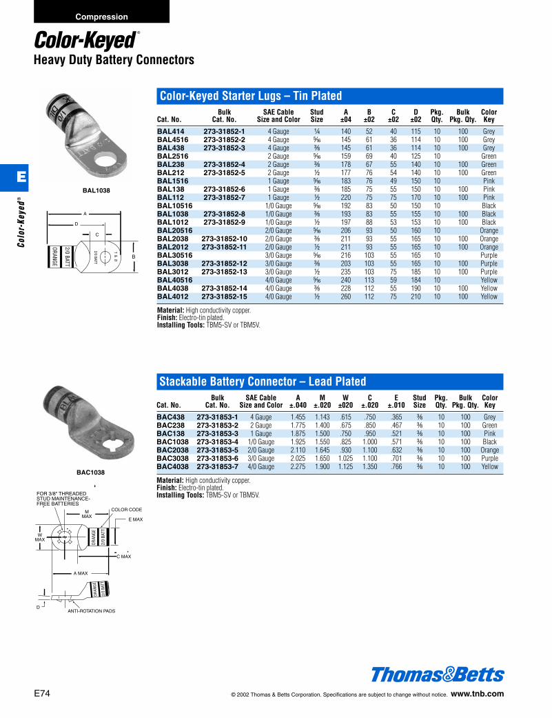
E74 © 2002 Thomas & Betts Corporation. Specifications are subject to change without notice. www.tnb.com
ORANGE
2/0 BATT
2/0 BATT
T&
B
Color-Keyed Starter Lugs – Tin PlatedBulk SAE Cable Stud A B C D Pkg. Bulk Color
Cat. No. Cat. No. Size and Color Size ±04 ±02 ±02 ±02 Qty. Pkg. Qty. Key
BAL414 273-31852-1 4 Gauge b 140 52 40 115 10 100 GreyBAL4516 273-31852-2 4 Gauge j 145 61 36 114 10 100 GreyBAL438 273-31852-3 4 Gauge c 145 61 36 114 10 100 GreyBAL2516 2 Gauge j 159 69 40 125 10 GreenBAL238 273-31852-4 2 Gauge c 178 67 55 140 10 100 GreenBAL212 273-31852-5 2 Gauge d 177 76 54 140 10 100 GreenBAL1516 1 Gauge j 183 76 49 150 10 PinkBAL138 273-31852-6 1 Gauge c 185 75 55 150 10 100 PinkBAL112 273-31852-7 1 Gauge d 220 75 75 170 10 100 PinkBAL10516 1/0 Gauge j 192 83 50 150 10 BlackBAL1038 273-31852-8 1/0 Gauge c 193 83 55 155 10 100 BlackBAL1012 273-31852-9 1/0 Gauge d 197 88 53 153 10 100 BlackBAL20516 2/0 Gauge j 206 93 50 160 10 OrangeBAL2038 273-31852-10 2/0 Gauge c 211 93 55 165 10 100 OrangeBAL2012 273-31852-11 2/0 Gauge d 211 93 55 165 10 100 OrangeBAL30516 3/0 Gauge j 216 103 55 165 10 PurpleBAL3038 273-31852-12 3/0 Gauge c 203 103 55 165 10 100 PurpleBAL3012 273-31852-13 3/0 Gauge d 235 103 75 185 10 100 PurpleBAL40516 4/0 Gauge j 240 113 59 184 10 YellowBAL4038 273-31852-14 4/0 Gauge c 228 112 55 190 10 100 YellowBAL4012 273-31852-15 4/0 Gauge d 260 112 75 210 10 100 Yellow
Material: High conductivity copper.Finish: Electro-tin plated.Installing Tools: TBM5-SV or TBM5V.
BAL1038
Heavy Duty Battery Connectors
Stackable Battery Connector – Lead PlatedBulk SAE Cable A M W C E Stud Pkg. Bulk Color
Cat. No. Cat. No. Size and Color ±.040 ±.020 ±020 ±.020 ±.010 Size Qty. Pkg. Qty. Key
BAC438 273-31853-1 4 Gauge 1.455 1.143 .615 .750 .365 c 10 100 GreyBAC238 273-31853-2 2 Gauge 1.775 1.400 .675 .850 .467 c 10 100 GreenBAC138 273-31853-3 1 Gauge 1.875 1.500 .750 .950 .521 c 10 100 PinkBAC1038 273-31853-4 1/0 Gauge 1.925 1.550 .825 1.000 .571 c 10 100 BlackBAC2038 273-31853-5 2/0 Gauge 2.110 1.645 .930 1.100 .632 c 10 100 OrangeBAC3038 273-31853-6 3/0 Gauge 2.025 1.650 1.025 1.100 .701 c 10 100 PurpleBAC4038 273-31853-7 4/0 Gauge 2.275 1.900 1.125 1.350 .766 c 10 100 Yellow
Material: High conductivity copper.Finish: Electro-tin plated.Installing Tools: TBM5-SV or TBM5V.
ORAN
GE
2/0
BATT
ORAN
GE
2/0
BATT
BAC1038
Compression
E
Colo
r-Ke
yed®
412031.E01 CK 3/5 3/13/03 8:22 PM Page 74
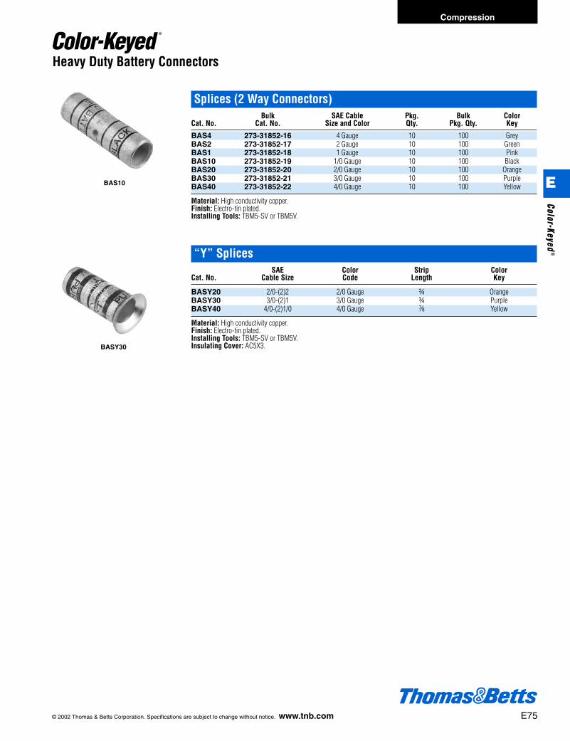
© 2002 Thomas & Betts Corporation. Specifications are subject to change without notice. www.tnb.com E75
Heavy Duty Battery Connectors
Splices (2 Way Connectors)Bulk SAE Cable Pkg. Bulk Color
Cat. No. Cat. No. Size and Color Qty. Pkg. Qty. Key
BAS4 273-31852-16 4 Gauge 10 100 GreyBAS2 273-31852-17 2 Gauge 10 100 GreenBAS1 273-31852-18 1 Gauge 10 100 PinkBAS10 273-31852-19 1/0 Gauge 10 100 BlackBAS20 273-31852-20 2/0 Gauge 10 100 OrangeBAS30 273-31852-21 3/0 Gauge 10 100 PurpleBAS40 273-31852-22 4/0 Gauge 10 100 Yellow
Material: High conductivity copper.Finish: Electro-tin plated.Installing Tools: TBM5-SV or TBM5V.
“Y” SplicesSAE Color Strip Color
Cat. No. Cable Size Code Length Key
BASY20 2/0-(2)2 2/0 Gauge f OrangeBASY30 3/0-(2)1 3/0 Gauge f PurpleBASY40 4/0-(2)1/0 4/0 Gauge g Yellow
Material: High conductivity copper.Finish: Electro-tin plated.Installing Tools: TBM5-SV or TBM5V.Insulating Cover: AC5X3.
BAS10
BASY30
Compression
E
Color-Keyed®
412031.E01 CK 3/5 3/13/03 8:22 PM Page 75

E76 © 2002 Thomas & Betts Corporation. Specifications are subject to change without notice. www.tnb.com
Heavy Duty Battery Cables
Color-Keyed ® Battery/Starter Cables
Thomas & Betts Color-Keyed® battery cable is engineered for optimum perfor-mance at both high and low temperatures. The abrasion resistant cable incorpo-rates insulation and fine stranding that provides a safe and reliable connection.• Made of fine flexible copper rope stranding
PVC jacket that conforms to SAE J1127 specifications.• Layer of paper separates insulation from copper
providing easy stripping with no stranding damage.• Temperature rated for 80°C.• Flexibility ideal for tight spaces and cold environments.• Color-Keyed® markings for fast and accurate identification.• Marked in 1ft. increments for easy measurements.
Heavy Duty Battery Cable
Thomas & Betts heavy duty battery cable is specially designed for demandingindustrial and OEM requirements. The 105°C rated cable is UL recognized andconforms to SAE J1127 specifications, making it ideal for demanding situations.• Heavier PVC Jacket that conforms to SAE J1127
specifications and is UL recognized.• Color-Keyed® markings for fast and accurate identification.• Marked in 1 ft. increments for easy measurements.• Layer of paper separating insulation from copper
providing easy stripping with no strand damage.• 600V rated available in bulk only.
Compression
E
Colo
r-Ke
yed®
412031.E01 CK 3/5 3/13/03 8:22 PM Page 76

© 2002 Thomas & Betts Corporation. Specifications are subject to change without notice. www.tnb.com E77
Heavy Duty Battery Cables
Battery CablesSAE Cable Cable Cable
Cat. No. Size Length Color
BC4-25 4 Gauge 25 Ft. Coil BlackBC2-25 2 Gauge 25 Ft. Coil BlackBC1-25 1 Gauge 25 Ft. Coil BlackBC10-25 1/0 Gauge 25 Ft. Coil BlackBC20-25 2/0 Gauge 25 Ft. Coil BlackBC30-25 3/0 Gauge 25 Ft. Coil BlackBC40-25 4/0 Gauge 25 Ft. Coil Black
BC4-25R 4 Gauge 25 Ft. Coil RedBC2-25R 2 Gauge 25 Ft. Coil RedBC1-25R 1 Gauge 25 Ft. Coil RedBC10-25R 1/0 Gauge 25 Ft. Coil RedBC20-25R 2/0 Gauge 25 Ft. Coil RedBC30-25R 3/0 Gauge 25 Ft. Coil RedBC40-25R 4/0 Gauge 25 Ft. Coil Red
BC4-100 4 Gauge 100 Ft. Coil BlackBC2-100 2 Gauge 100 Ft. Coil BlackBC1-100 1 Gauge 100 Ft. Coil BlackBC10-100 1/0 Gauge 100 Ft. Coil BlackBC20-100 2/0 Gauge 100 Ft. Coil BlackBC30-100 3/0 Gauge 100 Ft. Coil BlackBC40-100 4/0 Gauge 100 Ft. Coil Black
BC4-1000 4 Gauge 1000 Ft. Coil BlackBC2-500 2 Gauge 500 Ft. Coil BlackBC1-500 1 Gauge 500 Ft. Coil BlackBC10-500 1/0 Gauge 500 Ft. Coil BlackBC20-500 2/0 Gauge 500 Ft. Coil BlackBC30-500 3/0 Gauge 500 Ft. Coil BlackBC40-500 4/0 Gauge 500 Ft. Coil BlackBC4-1000R 4 Gauge 1000 Ft. Coil RedBC2-500R 2 Gauge 500 Ft. Coil RedBC1-500R 1 Gauge 500 Ft. Coil RedBC10-500R 1/0 Gauge 500 Ft. Coil RedBC20-500R 2/0 Gauge 500 Ft. Coil RedBC30-500R 3/0 Gauge 500 Ft. Coil RedBC40-500R 4/0 Gauge 500 Ft. Coil Red
Material: High conductivity copper.Finish: Electro-tin plated.Installing Tools: TBM5-SV or TBM5V.
BC10-25
BC10-25R
Compression
E
Color-Keyed®
412031.E01 CK 3/5 3/13/03 8:22 PM Page 77
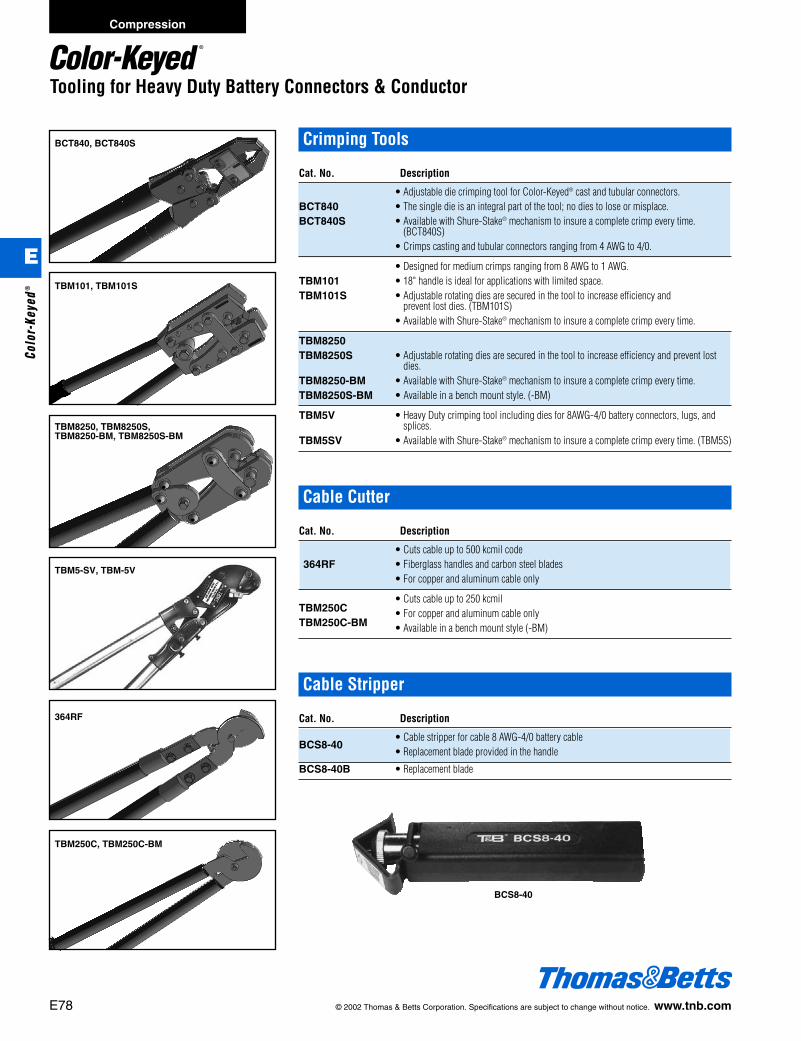
E78 © 2002 Thomas & Betts Corporation. Specifications are subject to change without notice. www.tnb.com
Tooling for Heavy Duty Battery Connectors & Conductor
BCT840, BCT840S
TBM101, TBM101S
TBM8250, TBM8250S, TBM8250-BM, TBM8250S-BM
TBM5-SV, TBM-5V
364RF
BCS8-40
TBM250C, TBM250C-BM
Crimping Tools
Cat. No. Description
• Adjustable die crimping tool for Color-Keyed® cast and tubular connectors.BCT840 • The single die is an integral part of the tool; no dies to lose or misplace.BCT840S • Available with Shure-Stake® mechanism to insure a complete crimp every time.
(BCT840S)• Crimps casting and tubular connectors ranging from 4 AWG to 4/0.
• Designed for medium crimps ranging from 8 AWG to 1 AWG.TBM101 • 18" handle is ideal for applications with limited space.TBM101S • Adjustable rotating dies are secured in the tool to increase efficiency and
prevent lost dies. (TBM101S)• Available with Shure-Stake® mechanism to insure a complete crimp every time.
TBM8250TBM8250S • Adjustable rotating dies are secured in the tool to increase efficiency and prevent lost
dies.TBM8250-BM • Available with Shure-Stake® mechanism to insure a complete crimp every time.TBM8250S-BM • Available in a bench mount style. (-BM)
TBM5V • Heavy Duty crimping tool including dies for 8AWG-4/0 battery connectors, lugs, andsplices.
TBM5SV • Available with Shure-Stake® mechanism to insure a complete crimp every time. (TBM5S)
Cable Cutter
Cat. No. Description
• Cuts cable up to 500 kcmil code364RF • Fiberglass handles and carbon steel blades
• For copper and aluminum cable only
TBM250C• Cuts cable up to 250 kcmil
TBM250C-BM• For copper and aluminum cable only• Available in a bench mount style (-BM)
Cable Stripper
Cat. No. Description
BCS8-40• Cable stripper for cable 8 AWG-4/0 battery cable• Replacement blade provided in the handle
BCS8-40B • Replacement blade
Compression
E
Colo
r-Ke
yed®
412031.E01 CK 3/5 3/13/03 8:22 PM Page 78

© 2002 Thomas & Betts Corporation. Specifications are subject to change without notice. www.tnb.com E79
Connector Tools
TBM25SGauging Requirements
GaugingCat. No. Nest Nom. – Tol.
Red .183 ± .006Blue .220 ± .008
TBM25S Gray .273 ± .008Brown .332 ± .008Green .414 ± .008
Gauging Procedure1. Rotate wheel to the desired nest.2. Squeeze handles with 5 lbs. - 15 lbs. force.3. Holding handles tightly closed, insert Go, NO-GO gauge into nest. GO gauge should enter freely. NO-GO gauge may
enter partially, but not pass completely thru the length of the nest area.
Conductor Size#10 #8 #6 #4 #2 #1Red Red Blue Gray Brown Green
Copper ConnectorsOne hole, short 54104 54134 54138 54107
54130 54105 54106 54142-TB54131 54135 54139 54143-TB54132 54136 54140 54145-TB
Two hole, short 54204 54205 54206 54207Splice, short 54504 54505 54506 54507One hole, long 54930BE 54905BE 54906BE 54942BETwo hole, long 54850BE 54852BE 54854BE 54856BESplice, long 54804 54805 54806 54807Cable Joints 54610 54615 54620Narrow Tongue 55112 55116C Taps 54705 54710 54715 54720 54725Motor Disconnects MD8 series MD6 series MD4 series MD2 series
Aluminum ConnectorsOne hole 60096 60101 60106
60096 60102 6010760099 60103 60108
60102 60109Splices 60500 60501 60507Bi Pins 61905A 61910AEquipment lugs 61102 61107
Installs lugs and splices over a wire range of #8to #2 copper and #10 to #6 aluminum. Alsoinstalls up to the green color coded C-Taps andMD2 series motor disconnect.A rotary color coded die wheel is rotated intoposition and each die has die code embossing.Requires two crimps per connector.
TBM4SThomas & Betts introduces a dieless adjustable crimper for Color-Keyed® compres-sion connectors. The TBM4S uses an adjustable indenter, eliminating the need forindividual dies. The tool easily adjusts by turning the knurled adjusting wheel andaligning the pointer with the proper terminal size. Its wide range of #8 to 250 kcmilfor copper lugs, and #8 to 4/0 for aluminum lugs, saves you the money of having tobuy and maintain the numerous dies.The tool is also equipped with the Shure-Stake® mechanism that insures a completedproper crimp each time.
Cat. No. Weight Length Height Width
TBM4S 5 lbs. 24f" 3" g"
SpecificationsLength: 24.75 in.Weight: 5.0 lbs.Handle Spread: 37 in.Range: Copper: #8 to 250 kcmil
Alum: #8 to 4/0
Connector
Cable SizeLine
Nest
Indentor
Pointer Slot
Type of Connector
Compression
E
Color-Keyed®
412031.E01 CK 3/5 3/13/03 8:22 PM Page 79

E80 © 2002 Thomas & Betts Corporation. Specifications are subject to change without notice. www.tnb.com
Connector Tools
TBM5 and TBM5SInstalls Copper Lugs from #8 to 250 kcmil, Aluminum from #10 to 4/0, C-Taps to 54750
Die Die GaugingCat. No. Cat. No. Color min. – max.
Red .165-.18113454 Blue .181-.201
Gray .230-.251Brown .260-.281
Green .313-.33513455 Pink .351-.371
Black .383-.406Orange .429-.454
13456 Purple .480-.503Yellow .529-.562
Gold .383-.40613457 Tan .429-.454
Olive .480-.503Ruby .533-.553
13458 White .580-.604
Case not included.295-31365M – Steel Carrying Case for TBM5(S)295-31365 – Plastic Case.Handle Spread Check1. Insert upper die in place.2. Close handles until lower die touches upper die.3. Measure distance between ends of handles. Distance must be 11" min. and 14" max. Tool Adjustment:1. Loosen locking screw.2. Turn adjusting screw clockwise to increase distance between handles; counterclockwise to decrease distance.3. Tighten locking screw when the proper distance between handles is achieved.Gauging Procedure1. Squeeze handles until jaws are fully closed.2. Holding handles tightly closed, insert GO, NO-GO gauge into nest. GO gauge should enter freely. NO-GO should not
enter.Notice: If tool fails any of the above tests, do not attempt repair or adjustment. Call T&B tool service center to arrange forrepair service. Any change, modification or alteration of the tool or use by the customer in a manner other than as speci-fied by T&B shall void all warranties express or implied and the customer shall, therefore, assume all liability for anydamage or injury caused by said changed, modified or altered tool or improper usage of such tool.
Lower Die
Upper DieMovable Jaw
Tool Head
GO, NO-GOGAUGE
Installs #8 through 250 kcmil copper connectorsand #10 to 4/0 aluminum. Includes color codedinstallation dies and available with Shure-Stake®
mechanism (TBM5S).Installing dies are color coded and die codeembossed.
TBM5TBM5S
Connector Cat. No. Cable RangeType Series Aluminum Copper
60000-60100-60200 (AL)#10-3/0 #8-250 kcmilLugs 54100-54200
–54800-54900 (CU)
Splices 60500-60900 (AL) #10-3/054500-54800 (CU) – #8-250 kcmil
#10 Main w #10 BranchC-taps 54705 (CU)-54750 – to
1/0 Main w 1/0 Branch
Wire19,590 Cir Mils
Joints54600 (CU) – to
244,020 Cir Mils
Compression
E
Colo
r-Ke
yed®
412031.E01 CK 3/5 3/13/03 8:22 PM Page 80
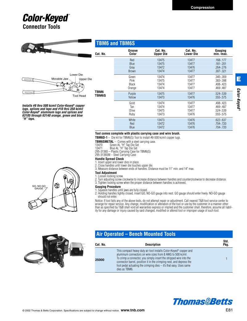
© 2002 Thomas & Betts Corporation. Specifications are subject to change without notice. www.tnb.com E81
Connector Tools
Lower Die
Upper DieMovable Jaw
Tool Head
TBM6 and TBM6SGroove Cat. No. Cat. No. Gauging
Cat. No. Color Upper Die Lower Die min.-max.
Red 13475 13477 .168-.177Blue 13475 13477 .181-.201Gray 13472 13476 .264-.276
Brown 13474 13477 .307-.321
Green 13474 13477 .345-.359Pink 13475 13477 .383-.398Black 13474 13477 .408-.423
Orange 13474 13477 .469-.487
Purple 13475 13477 .524-.539Yellow 13473 13476 .555-.575
Gold 13474 13477 .408-.423Tan 13474 13477 .469-.487
Olive 13475 13477 .524-.539Ruby 13473 13476 .555-.575
White 13473 13476 .622-.637Red 13472 13476 .704-.720Blue 13472 13476 .704-.720
Tool comes complete with plastic carrying case and wire brush.TBM6D-1 – Die kit for TBM6(S) Tool to install #8-500 kcmil copper lugs.TBM6SMETAL – Comes with a steel carrying case.13470 Green AL “H” Tap Die Set13471 Blue AL “H” Tap Die Set295-31365 – Plastic Carrying Case for TBM6(S)295-31365M – Steel Carrying CaseHandle Spread Check1. Insert upper and lower dies in place.2. Close handles until lower die touches upper die.3. Measure distance between ends of handles. Distance must be 11" min. and 14" max.Tool Adjustment1. Loosen locking screw.2. Turn adjusting screw clockwise to increase distance between handles and counterclockwise to decrease distance.3. Tighten locking screw when the proper distance between handles is achieved.Gauging Procedure1. Squeeze handles until jaws are fully closed.2. Holding handles tightly closed, insert GO, NO-GO gauge into nest. GO gauge should enter freely. NO-GO gauge
should not enter.Notice: If tool fails any of the above tests, do not attempt repair or adjustment. Call nearest T&B tool service center toarrange for repair service. Any change, modification or alteration of the tool or use by the customer in a manner otherthan as specified by T&B shall void all warranties express or implied and the customer shall, therefore, assume all liabil-ity for any damage or injury caused by said changed, modified or altered tool or improper usage of such tool.
GO, NO-GOGAUGE
Installs #8 thru 500 kcmil Color-Keyed® copperlugs, splices and taps and #10 thru 350 kcmilColor-Keyed® aluminum lugs and splices and63105 through 63140 orange, green and blue“H” taps.
TBM6TBM6S
Air Operated – Bench Mounted ToolsStd.
Cat. No. Description Pkg.
25000
This compact heavy duty air tool installs Color-Keyed® copper and
1aluminum connectors on wire sizes from 8 AWG to 500 kcmil. To crimp a connector, you simply insert the stripped wire into the connector barrel, position it in the crimping nest, and depress thefoot pedal actuating the crimping dies – it’s that easy. Uses same dies as TBM6.
Compression
E
Color-Keyed®
412031.E01 CK 3/5 3/13/03 8:22 PM Page 81
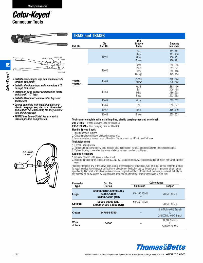
E82 © 2002 Thomas & Betts Corporation. Specifications are subject to change without notice. www.tnb.com
TBM8 and TBM8SDie
Die Groove GaugingCat. No. Cat. No. Color min.-max.
Red .165-.181
13461Blue .181-.210Grey .230-.251
Brown .260-.281
Green .313-.335
13462Pink .351-.371Black .383-.406
Orange .429-.454
13463Purple .480-.503Yellow .529-.562
Gold .383-.406
13464Tan .429-.454
Olive .480-.503Ruby .533-.553
13465 White .609-.632
13466 Red .653-.677
13467 Blue .686-.710
13468 Brown .855-.833
Tool comes complete with installing dies, plastic carrying case and wire brush.295-31365 – Plastic Carrying Case for TBM8(S)295-31365M – Steel Carrying Case for TBM8(S)Handle Spread Check1. Insert upper die in place.2. Close handles until lower die touches upper die.3. Measure distance between ends of handles. Distance must be 11" min. and 14" max.Tool Adjustment1. Loosen locking screw.2. Turn adjusting screw clockwise to increase distance between handles; counterclockwise to decrease distance.3. Tighten locking screw when the proper distance between handles is achieved.Gauging Procedure1. Squeeze handles until jaws are fully closed.2. Holding handles tightly closed, insert GO, NO-GO gauge into nest. GO gauge should enter freely. NO-GO should not
enter.*Notice: If tool fails any of the above tests, do not attempt repair or adjustment. Call T&B tool service center to arrangefor repair service. Any change, modification or alteration of the tool or use by the customer in a manner other than asspecified by T&B shall void all warranties express or implied and the customer shall, therefore, assume all liability forany damage or injury caused by said changed, modified or altered tool or improper usage of such tool.
Connector Cat. No. Cable RangeType Series Aluminum Copper
60000-60100-60200 (AL)#10-350 KCMILLugs 54100-54200
–#8-500 KCMIL
54800-54900 (CU)
Splices60500-60900 (AL) #10-350 KCMIL
#8-500 KCMIL54000-54500-54800 (CU) –
#10 Main w/#10 BranchC-taps 54705-54750 – to
250 KCMIL w/1/0 Branch
Wire19,590 Cir Mils
Joints54600 – to
244,020 Cir Mils
Connector Tools
• Installs code copper lugs and connectors #8through 500 kcmil.
• Installs aluminum lugs and connectors #10through 350 kcmil.
• Installs all code copper compression jointsand (small) “C” taps.
• Installs Blackburn® compression lugs andconnectors.
• Comes complete with installing dies in a plastic carrying case; dies are color-codedand feature die-embossing for easy installa-tion and inspection.
• TBM8S has Shure-Stake® feature whichinsures positive compression.
LOWER DIE
UPPER DIEMOVABLE JAW
TOOL HEAD
GO-NO GOGAUGE
TBM8TBM8S
Compression
E
Colo
r-Ke
yed®
412031.E01 CK 3/5 3/13/03 8:22 PM Page 82

© 2002 Thomas & Betts Corporation. Specifications are subject to change without notice. www.tnb.com E83
Connector Tools
Installs Color-Keyed® Connectors• Fiberglass Handles.• Two Stage Pump for Rapid Advance.• All Cat. No. 15500 Series die sets are
compatible with 13100A & TBM14M Tool.• Installs Copper Connectors to 900 kcmil and
Aluminum Connectors to 750 kcmil.• Installs copper “C” taps through #54775 and
aluminum “H” taps through #63148• Installs grid connectors through 500 kcmil
and 5⁄8" rod.• Uses standard T&B Color-Keyed® dies
supplied with carrying case.
14-Ton Manual Hydraulic Insulated ToolCat. No. Description
Self-contained hydraulic crimping tool installs copper and aluminum Color-Keyed® connectors; copper and aluminum lugs and 2-way connectors to 900 kcmil; copper C-taps thru #54775, aluminum “H” taps
TBM14M thru #63148; grid connectors thru 250 kcmil, e" rod; features rapid-ram advance mechanism for fast installation, and short fiberglass handles for confined work spaces; develops 14-ton compression force, and uses standard T&B shell dies, not included; includes carrying case.
Output Force 14 tons max.Weight, less case 15.4 lbs.Maximum Length 24.4 in.Swivel “C” Head rotates 180°
Installation Range for Color-Keyed® Connectors
Lugs Splices
Copper No. 8 AWG to 900 kcmil No. 8 AWG to 900 kcmil
Aluminum No. 10 AWG to 750 kcmil No. 10 AWG to 750 kcmil
TBM14MG – Gauge and Testing dies in carrying case.
Die Table
Cat. No. Die Code Color Copper Size AL Size *C-Taps
Compression
E
Color-Keyed®
412031.E01 CK 3/5 3/13/03 8:22 PM Page 83
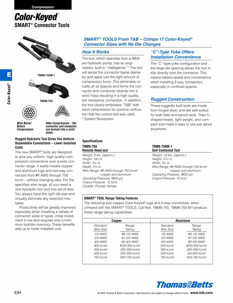
E84 © 2002 Thomas & Betts Corporation. Specifications are subject to change without notice. www.tnb.com
SMART® Connector Tools
Rugged Hydraulic Tool Gives You UniformDependable Connections – Lower InstalledCostsThe new SMART® tools are designedto give you uniform, high quality com-pression connections over a wide con-nector range. It easily installs copperand aluminum lugs and two-way con-nectors from #8 AWG through 750kcmil – without changing dies. For thespecified wire range, all you need isone hydraulic tool and one set of dies.You always have the right die size andvirtually eliminate any selection mis-takes.
Productivity will be greatly improvedespecially when installing a variety ofconnector sizes or types. Initial invest-ment is low and requires only a mini-mum tool/die inventory. These benefitsadd up to lower installed cost.
SMART ® TOOLS From T&B – Crimps 17 Color-Keyed ®
Connector Sizes with No Die Changes
SMART® TOOL Range Taking FeaturesThe following size copper Color-Keyed® lugs and 2-way connectors, whencrimped with the SMART® TOOLS, Cat Nos. TBM8-750, TBM8-750-M1 producethese range taking capabilities:
Copper AluminumStandard Range Standard RangeWire Size Taking Wire Size Taking
1/0-AWG #6-1/0 AWG 1/0-AWG #6-1/0 AWG2/0-AWG #1-2/0 AWG 2/0-AWG #1-2/0 AWG4/0-AWG #2-4/0 AWG 4/0-AWG #2-4/0 AWG300 kcmil #2/0-300 kcmil 300 kcmil #2/0-300 kcmil350 kcmil 250-350 kcmil 350 kcmil 250-350 kcmil500 kcmil 250-500 kcmil 500 kcmil 4/0-500 kcmil750 kcmil 500-750 kcmil 750 kcmil 500-750 kcmil
Wire BarrelBeforeCompression
After Compression – theconnector and conductorare formed into a solidmass.
Specifications
TBM8-750 TBM8-750M-1Remote Head tool Self-Contained ToolWeight: 9 lbs. (approx.) Weight: 13 lbs. (approx.)Height: 141⁄2 in. Height: 211⁄2 in.Width: 47⁄32 in. Width: 47⁄32 in.Depth: 2 9⁄16 in. Wire Range: #8 AWG through 750 kcmil Wire Range: #8 AWG through 750 kcmil copper and aluminum
copper and aluminum Operating Pressure: 9800 psiOperating Pressure: 9800 psi Output Pressure: 12 tonsOutput Pressure: 12 tonsCoupler: Pioneer, female
How It WorksThe tool, which operates from a 9800psi hydraulic pump, has an engi-neered, built-in “intelligence.”* The toolwill sense the connector barrel diame-ter and apply just the right amount ofcompression force. This eliminates vir-tually all air spaces and forms the con-nector and conductor strands into asolid mass resulting in a high quality,low resistance connection. In addition,the tool clearly embosses “T&B” witheach compression for positive verifica-tion that the correct tool was used.* System Novopress
“C”-Type Yoke OffersInstallation ConvenienceThe “C”-type yoke configuration andthe large die spacing allows the tool toslip directly over the connector. Thismeans added speed and conveniencewhen installing 2-way connectors,especially in confined spaces.
Rugged ConstructionThese ruggedly built tools are madefrom forged steel, and are well suitedfor both field and bench work. Their C-shaped heads, light weight, and com-pact size make it easy to use just aboutanywhere.
TBM8-750M-1
TBM8-750
Compression
E
Colo
r-Ke
yed®
412031.E01 CK 3/5 3/13/03 8:22 PM Page 84
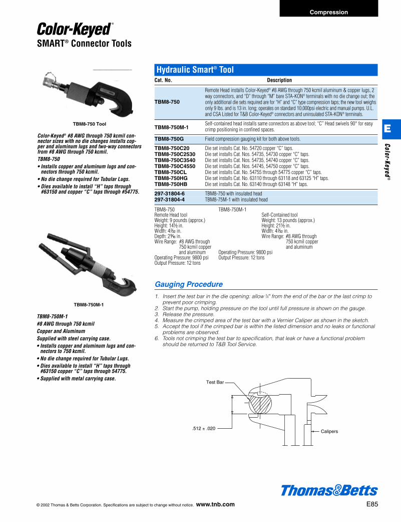
© 2002 Thomas & Betts Corporation. Specifications are subject to change without notice. www.tnb.com E85
SMART® Connector Tools
TBM8-750 Tool
Color-Keyed® #8 AWG through 750 kcmil con-nector sizes with no die changes installs cop-per and aluminum lugs and two-way connectorsfrom #8 AWG through 750 kcmil.TBM8-750• Installs copper and aluminum lugs and con-
nectors through 750 kcmil.• No die change required for Tubular Lugs.• Dies available to install “H” taps through
#63150 and copper “C” taps through #54775.
TBM8-750M-1
TBM8-750M-1#8 AWG through 750 kcmilCopper and AluminumSupplied with steel carrying case.• Installs copper and aluminum lugs and con-
nectors to 750 kcmil.• No die change required for Tubular Lugs.• Dies available to install “H” taps through
#63150 copper “C” taps through 54775.• Supplied with metal carrying case.
Hydraulic Smart® ToolCat. No. Description
TBM8-750
Remote Head installs Color-Keyed® #8 AWG through 750 kcmil aluminum & copper lugs, 2way connectors, and “D” through “M” bare STA-KON® terminals with no die change out; theonly additional die sets required are for “H” and “C” type compression taps; the new tool weighsonly 9 lbs. and is 13 in. long; operates on standard 10,000psi electric and manual pumps. U.L.and CSA Listed for T&B Color-Keyed® connectors and uninsulated STA-KON® terminals.
TBM8-750M-1Self-contained head installs same connectors as above tool; “C” Head swivels 90° for easycrimp positioning in confined spaces.
TBM8-750G Field compression gauging kit for both above tools.
TBM8-750C20 Die set installs Cat. No. 54720 copper “C” taps.TBM8-750C2530 Die set installs Cat. Nos. 54735, 54730 copper “C” taps.TBM8-750C3540 Die set installs Cat. Nos. 54735, 54740 copper “C” taps.TBM8-750C4550 Die set installs Cat. Nos. 54745, 54750 copper “C” taps.TBM8-750CL Die set installs Cat. No. 54755 through 54775 copper “C” taps.TBM8-750HG Die set installs Cat. No. 63110 through 63118 and 63125 “H” taps.TBM8-750HB Die set installs Cat. No. 63140 through 63148 “H” taps.
297-31804-6 TBM8-750 with insulated head297-31804-4 TBM8-75M-1 with insulated head
TBM8-750 TBM8-750M-1Remote Head tool Self-Contained toolWeight: 9 pounds (approx.) Weight: 13 pounds (approx.)Height: 14d in. Height: 21d in.Width: 4r in. Width: 4r in.Depth: 2l in. Wire Range: #8 AWG throughWire Range: #8 AWG through 750 kcmil copper
750 kcmil copper and aluminumand aluminum Operating Pressure: 9800 psi
Operating Pressure: 9800 psi Output Pressure: 12 tonsOutput Pressure: 12 tons
Gauging Procedure
1. Insert the test bar in the die opening: allow 3⁄4" from the end of the bar or the last crimp toprevent poor crimping.
2. Start the pump, holding pressure on the tool until full pressure is shown on the gauge.3. Release the pressure.4. Measure the crimped area of the test bar with a Vernier Caliper as shown in the sketch.5. Accept the tool if the crimped bar is within the listed dimension and no leaks or functional
problems are observed.6. Tools not crimping the test bar to specification, that leak or have a functional problem
should be returned to T&B Tool Service.
Calipers.512 ± .020
Test Bar
Compression
E
Color-Keyed®
412031.E01 CK 3/5 3/13/03 8:22 PM Page 85

E86 © 2002 Thomas & Betts Corporation. Specifications are subject to change without notice. www.tnb.com
Installation Tools
Dieless Tool
Weight: 18.75 lbs.Operating Pressure: 10,000 PSIForce: 12 Tons
Tubular Connector Range:Copper – #8 AWG through 750 kcmilAluminum – #12 AWG through 600 kcmil
Die Code / Color
21 / Red24 / Blue29 / Grey33 / Brown37 / Green42 / Pink45 / Black & Gold50 / Orange & Tan54 / Purple & Olive60 / Ruby66 / White71 / Red76 / Blue80 / No Color87 / Brown94 / Green99 / Pink106 / Black
Tool Replaces These Aluminum Common OD Die CodesCode Die References Wire Range
1 5/8, BG, TU, G, PEACH, B58CS, U-BG, 52 2/0 STR - #8 STR2 840, K840, 845, TX, 76, 249, EEI-11A, CSA24 4/0 ACSR-#6 AWG3 B840EA, 1-1/8, 96H, 655, 321, CSA26, EEI-13A 500 CPT-3/0 STR.4 106H, B20AH, 318, 1-5-16, EEI-14A, CSA28 750 CPT-397.5 18/1
Color-Keyed® Dieless ToolCat. No. Crimp Range
TBMSHX-1 #8 AWG through 750 kcmil CU / #12 AWG through 600 kcmil AL
Abstract to Reality!
No longer a dream or a wish for onetool without worrying about which dieto use or “Where The Dies Are”! TheTBMSHX-1 will crimp all your needsthrough 750MCM Copper and here’sthe miracle… a “Hex Crimp” with noflash!Order this tool today and test the results.Use your existing hydraulic system or ifyou need portability, try it with our newPumpac II and you will find an unbeat-able package.Refer to the specifications and productinformation below for requesting thistruly amazing tool. Our sales personswill also be happy to demonstrate thetool and the amazing results for makingthe best connections.
Unbeatable Package!
Combined with our new Pumpac II,T&B’S newest hydraulic pump, this toolcan go anywhere you need it.The new Pumpac battery-poweredhydraulic pumps come with improvedpower capabilities. Rated 10,000 PSI itcan power any remote hydraulic tools.The battery power source delivers overa hundred crimps for large cable sizes,and both will charge in less than anhour.Combine the latest in tool technologyand be the envy of your competitors!The features will keep you ahead withefficient and low cost installations.
NEW
3d
15d
Compression
E
Colo
r-Ke
yed®
412031.E01 CK 3/5 3/13/03 8:22 PM Page 86

© 2002 Thomas & Betts Corporation. Specifications are subject to change without notice. www.tnb.com E87
Compression
Battpac® Battery Powered Compression and Cutting Tools
6-Ton Battery Powered Compression ToolThe TBM6BSCR is designed to crimp commonly used lugs, splices, serviceentrance connectors, H and C-taps. It can be easily carried and used in limitedaccess areas because of its swivel head and compact design. The unique openyoke is also advantageous for C-tap, H-tap and splicing applications. Its six-tonoutput is equal to any comparable hand-held, hydraulic compression tool and farexceeds any mechanical crimper.A built-in factory pre-set 10,000 psi by-pass cartridge assures a complete com-pression every time. Always consult Thomas & Betts for proper die/connector combinations or read the information on the connector package. Accepts std. T&Bsix-ton dies and Blackburn® OD58 series dies. Will not do splices over 350 MCM.
Cat. No. Description
TBM6BSCR 6-Ton Battery Powered Compression Tool.
14-Ton Battery Powered Compression ToolThe TBM14BSCR is a self-contained battery operated 14-ton compression tool. Thelarge jaw opening is 1.65" which accepts mid-span copper and aluminum splicesand cables up to 750 kcmil. When the splices are compressed they can be removedthrough the large jaw. This tool accepts T&B and Blackburn shell type dies.A built-in, pre-set 10,000 psi bypass cartridge will audibly kick out when the 14-tonpressure is achieved. Portability and handling is easy because the TBM14BSCR system is self containedand compact. There is no tool set-up time or extra power source needed. Makessplicing a breeze. And with one finger trigger operation fatigue and muscle relatedstrains are nearly eliminated. Safer work habits result from using these tools.
Cat. No. Description
TBM14BSCR 14-Ton Battery Powered Compression Tool
Specifications:Output 6 tonWeight 8 lbs. w/batterySize 13" x 12" x 3"
Connector range:Lugs & splices #8-600 kcmil CU
#10-400 kcmil ALH - taps 4/0C - taps 54705 through 54750
Standard Battpac ® Kit Includes:1 battery powered tool1 carrying strap1 carrying case2 CRCTBP batteries1 CRCTQC 15 minute AC charger
Standard Battpac® Kit Includes:1 battery powered tool1 carrying strap1 carrying case2 CRCTBP batteries1 CH-3TR 15 minute AC charger
NOTE: When ordering the “Smart®” battery add suffix “– SM” (Example: TBM6BSCR – SM).TBM6MG – Jaw Pressure Verification Gauge.
Specifications:Output 14 tonWeight 20 lbs. w/batterySize 19" L x 3.5"W x 10.5"HJaw opening 1.65"
Connector range:Lugs & splices 900 kcmil CU, 750 kcmil AL
NOTE: When ordering the “Smart®” battery add suffix “– SM” (Example: TBM6BSCR – SM)TBM14MG – Jaw Pressure Verification Gauge.
Battpac® Battery Powered Tools
Designed for years of use, T&B qualityBattpac® tools are time-tested, rugged,and dependable compression tools.Battpac® products are all essential com-ponent and commercial, and industrialconnector and grounding installations.
• Hermetically Sealed Unit (Motor notexposed to environment/elements).
• Special 14.4V Izumi Battery (fits alltools).
• Broadest Family of Battery Tools.
• Robust Tool Design.• Insulated Crimp Heads.• 15-20 Minute Battery Recharge.• 5 Year Warranty (Includes Battery)
E
Color-Keyed®
412031.E01 CK 3/5 3/13/03 8:22 PM Page 87

E88 © 2002 Thomas & Betts Corporation. Specifications are subject to change without notice. www.tnb.com
Compression
15-Ton Battery Powered Compression Tool You’ve got the power with this self contained 15-ton tool. This exclusive state of theart tool features superior hydraulics with an internally sealed oil circuit, eliminatingany need for refilling. Its high grade forged steel head includes a rotation of 180degrees, a rapid two stage advance compression system, and accepts cables upto 1000 kcmil copper and aluminum.The TBM15BSCR’s entire circuitry is solid state, and the pumping circuit isdesigned with high and low stages.The high capacity battery offers 60% more compression cycles than regular batter-ies and can be recharged in 25 minutes or less. The TBM15BSCR will accept allT&B dies.
Cat. No. Description
TBM15BSCR 15-Ton Battery Powered Compression Tool.
NOTE: When ordering the “Smart®” battery add suffix “– SM” (Example: TBM58BSCT – SM).TBM15MG – Jaw Pressure Verification Gauge.
Standard Battpac® Kit Includes:1 battery powered tool1 carrying strap1 carrying case2 CRCTBP batteries1 CH-3TR 15 minute AC charger
Specifications:Output 15 tonWeight 23.75 lbs. w/batterySize 21" L x 3.5"W x 11"HWarranty 2 years Tool & Battery
Connector range:Up to 1500 kcmil CU, 1000 AL
Battpac® Battery Powered Compression and Cutting Tools
12-Ton Dieless Battery Powered Compression Tool
This is a self-contained 12-ton compression tool that features a unique dielesscompression system. Using commonly found 14.4V battery, the TBM8-750BSCRputs portability and convenience of a dieless compression tool in a lightweight,economical package. 8 AWG – 750 kcmil range.
12-Ton Dieless Compression ToolCat. No. Description
TBM8-750BSCR Battpac® LT 12-Ton Compression Tool. Includes carrying case, charger,two-batteries, carry strap (no dies).
Specifications:Application Range: 8 AWG – 750 kcmil Copper Connectors, 750 kcmil AluminumCrimping Force: 12-Ton Compression ToolRated Operating Pressure: 10,000 PSIBatteries: 14.4V BatteriesConstruction: Open Forged Steel HeadDies: Die-less CrimpVerification: Positive VerificationWeight: 9 Lbs. with BatteryU.L. Listed
NEW
E
Colo
r-Ke
yed®
412031.E01 CK 3/5 3/13/03 8:22 PM Page 88
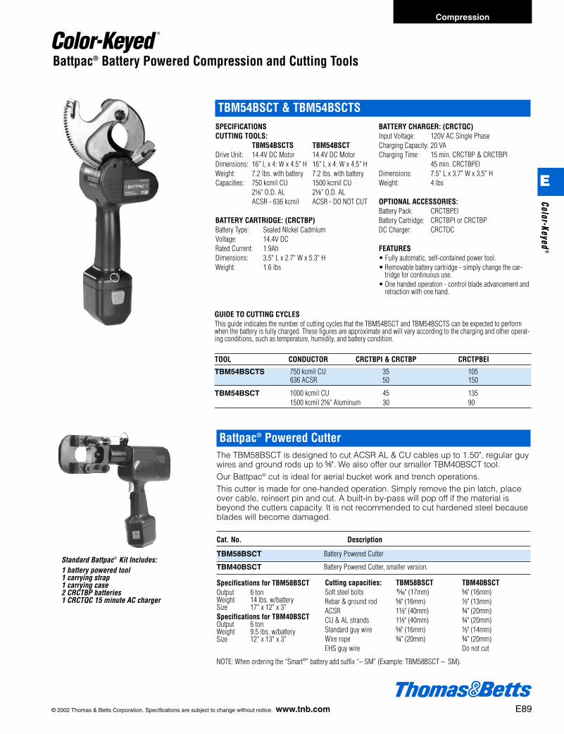
© 2002 Thomas & Betts Corporation. Specifications are subject to change without notice. www.tnb.com E89
Compression
SPECIFICATIONSCUTTING TOOLS:
TBM54BSCTS TBM54BSCTDrive Unit: 14.4V DC Motor 14.4V DC MotorDimensions: 16" L x 4: W x 4.5" H 16" L x 4: W x 4.5" HWeight: 7.2 lbs. with battery 7.2 lbs. with batteryCapacities: 750 kcmil CU 1500 kcmil CU
2a" O.D. AL 2a" O.D. AL ACSR - 636 kcmil ACSR - DO NOT CUT
BATTERY CARTRIDGE: (CRCTBP)Battery Type: Sealed NIckel CadmiumVoltage: 14.4V DCRated Current: 1.9AhDimensions: 3.5" L x 2.7" W x 5.3" HWeight: 1.6 lbs
BATTERY CHARGER: (CRCTQC)Input Voltage: 120V AC Single PhaseCharging Capacity: 20 VACharging Time: 15 min. CRCTBP & CRCTBPI
45 min. CRCTBPEIDimensions: 7.5" L x 3.7" W x 3.5" HWeight: 4 lbs
OPTIONAL ACCESSORIES:Battery Pack: CRCTBPEIBattery Cartridge: CRCTBPI or CRCTBPDC Charger: CRCTDC
FEATURES• Fully automatic, self-contained power tool.• Removable battery cartridge - simply change the car-
tridge for continuous use.• One handed operation - control blade advancement and
retraction with one hand.
TBM54BSCT & TBM54BSCTS
GUIDE TO CUTTING CYCLESThis guide indicates the number of cutting cycles that the TBM54BSCT and TBM54BSCTS can be expected to performwhen the battery is fully charged. These figures are approximate and will vary according to the charging and other operat-ing conditions, such as temperature, humidity, and battery condition.
TOOL CONDUCTOR CRCTBPI & CRCTBP CRCTPBEI
TBM54BSCTS 750 kcmil CU 35 105636 ACSR 50 150
TBM54BSCT 1000 kcmil CU 45 1351500 kcmil 2a" Aluminum 30 90
Battpac® Battery Powered Compression and Cutting Tools
Battpac® Powered CutterThe TBM58BSCT is designed to cut ACSR AL & CU cables up to 1.50", regular guywires and ground rods up to e". We also offer our smaller TBM40BSCT tool.Our Battpac® cut is ideal for aerial bucket work and trench operations.This cutter is made for one-handed operation. Simply remove the pin latch, placeover cable, reinsert pin and cut. A built-in by-pass will pop off if the material isbeyond the cutters capacity. It is not recommended to cut hardened steel becauseblades will become damaged.
Cat. No. Description
TBM58BSCT Battery Powered Cutter
TBM40BSCT Battery Powered Cutter, smaller version.
Cutting capacities: TBM58BSCT TBM40BSCTSoft steel bolts W" (17mm) e" (16mm)Rebar & ground rod e" (16mm) d" (13mm)ACSR 1d" (40mm) f" (20mm)CU & AL strands 1d" (40mm) f" (20mm)Standard guy wire e" (16mm) d" (14mm)Wire rope f" (20mm) f" (20mm)EHS guy wire Do not cut
Specifications for TBM58BSCTOutput 6 tonWeight 14 lbs. w/batterySize 17" x 12" x 3"Specifications for TBM40BSCTOutput 6 tonWeight 9.5 lbs. w/batterySize 12" x 13" x 3"
Standard Battpac® Kit Includes:1 battery powered tool1 carrying strap1 carrying case2 CRCTBP batteries1 CRCTQC 15 minute AC charger
NOTE: When ordering the “Smart®” battery add suffix “– SM” (Example: TBM58BSCT – SM).
E
Color-Keyed®
412031.E01 CK 3/5 3/13/03 8:23 PM Page 89
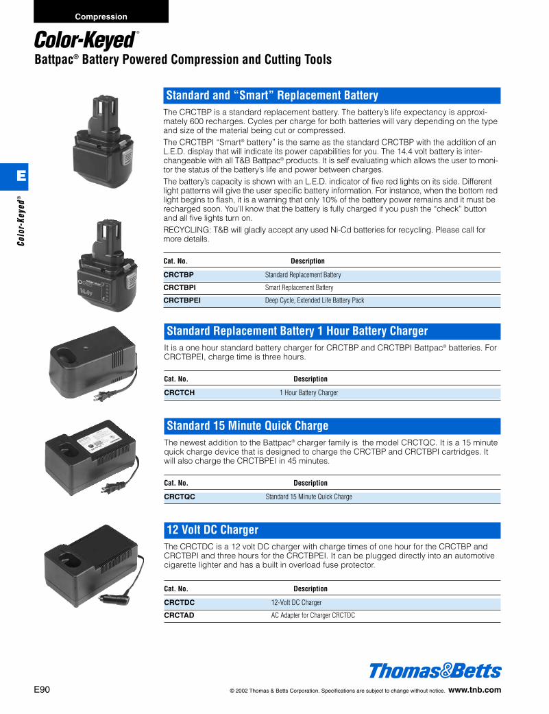
E90 © 2002 Thomas & Betts Corporation. Specifications are subject to change without notice. www.tnb.com
Compression
Battpac® Battery Powered Compression and Cutting Tools
Standard and “Smart” Replacement BatteryThe CRCTBP is a standard replacement battery. The battery’s life expectancy is approxi-mately 600 recharges. Cycles per charge for both batteries will vary depending on the typeand size of the material being cut or compressed.The CRCTBPI “Smart® battery” is the same as the standard CRCTBP with the addition of anL.E.D. display that will indicate its power capabilities for you. The 14.4 volt battery is inter-changeable with all T&B Battpac® products. It is self evaluating which allows the user to moni-tor the status of the battery’s life and power between charges.The battery’s capacity is shown with an L.E.D. indicator of five red lights on its side. Differentlight patterns will give the user specific battery information. For instance, when the bottom redlight begins to flash, it is a warning that only 10% of the battery power remains and it must berecharged soon. You’ll know that the battery is fully charged if you push the “check” buttonand all five lights turn on.RECYCLING: T&B will gladly accept any used Ni-Cd batteries for recycling. Please call formore details.
Cat. No. Description
CRCTBP Standard Replacement Battery
CRCTBPI Smart Replacement Battery
CRCTBPEI Deep Cycle, Extended Life Battery Pack
Standard Replacement Battery 1 Hour Battery ChargerIt is a one hour standard battery charger for CRCTBP and CRCTBPI Battpac® batteries. ForCRCTBPEI, charge time is three hours.
Cat. No. Description
CRCTCH 1 Hour Battery Charger
Standard 15 Minute Quick ChargeThe newest addition to the Battpac® charger family is the model CRCTQC. It is a 15 minutequick charge device that is designed to charge the CRCTBP and CRCTBPI cartridges. Itwill also charge the CRCTBPEI in 45 minutes.
Cat. No. Description
CRCTQC Standard 15 Minute Quick Charge
12 Volt DC ChargerThe CRCTDC is a 12 volt DC charger with charge times of one hour for the CRCTBP andCRCTBPI and three hours for the CRCTBPEI. It can be plugged directly into an automotivecigarette lighter and has a built in overload fuse protector.
Cat. No. Description
CRCTDC 12-Volt DC Charger
CRCTAD AC Adapter for Charger CRCTDC
E
Colo
r-Ke
yed®
412031.E01 CK 3/5 3/13/03 8:23 PM Page 90

© 2002 Thomas & Betts Corporation. Specifications are subject to change without notice. www.tnb.com E91
Compression
Battpac® LT 14-Ton Ordering InformationCat. No. Description
BPLT14BSCR Battpac® LT 14-Ton Compression Tool. Includes carrying case, charger,two-batteries, carry strap.
Specifications:Application Range: 8 AWG – 900 kcmil Copper Connectors, 750 kcmil AluminumCrimping Force: 14-Ton Compression ToolRated Operating Pressure: 10,000 PSIBatteries: 14.4V BatteriesConstruction: Open Forged Steel HeadDies: Dies are interchangeable with TBM14M Mechanical Hydraulic ToolWeight: 15.4 Lbs. with BatteryU.L. Listed
Battpac® Battery Powered Compression and Cutting Tools
Battpac® LT 6-Ton Ordering InformationCat. No. Description
TBM62BSCR Battpac® LT Tool Kit. Includes tool, two batteries, charger, shoulder strap, wriststrap, carrying case (no dies).
TBM6240BSCR Complete Battpac® LT Tool Kit with dies TBM6221 through TBM6254.
TBM62500BSCR Complete Battpac® LT Tool Kit with dies TBM6221 through TBM6287.
Specifications:Application Range: Suitable for installing electrical compession connectors for conductors up to 500 kcmil CU,
350 AL.Crimping Force: 6 tonsRated Operating Pressure: 8,700 PSIDimensions:
Length: 11W”Width: 3f”Height: 11g”Weight (with battery) 8 lbs.Motor 14.4 VBattery (DC) 14.4V – 2.0 AhSafety: Unit is provided with maximum pressure relief valve.
Battpac® LT tools put the power in yourhand, when and where you need itmost. You’re also left with a free handto control the operation and positionthe connector with greater ease. Bestof all, Battpac® LT tools are affordablypriced to make it comfortable on yourwallet as well.
T&B’s Battpac® LT tools includethese prominent features:• Ventilated, Air Cooled.• Industry Standard Mikita 14.4V
Battery (available at retail stores) (fitsall tools except LT pumpac which is24V Mikita).
• Distinctive Ergonomic Design.• Reduced Weight.• Lower Cost.• Un-insulated Crimp Heads.• 1 Hour Battery Recharge.• 1 Year Warranty (Includes Battery).
Battpac ® LT Powered Compression Tool
NEW
E
Color-Keyed®
412031.E01 CK 3/5 3/13/03 8:23 PM Page 91
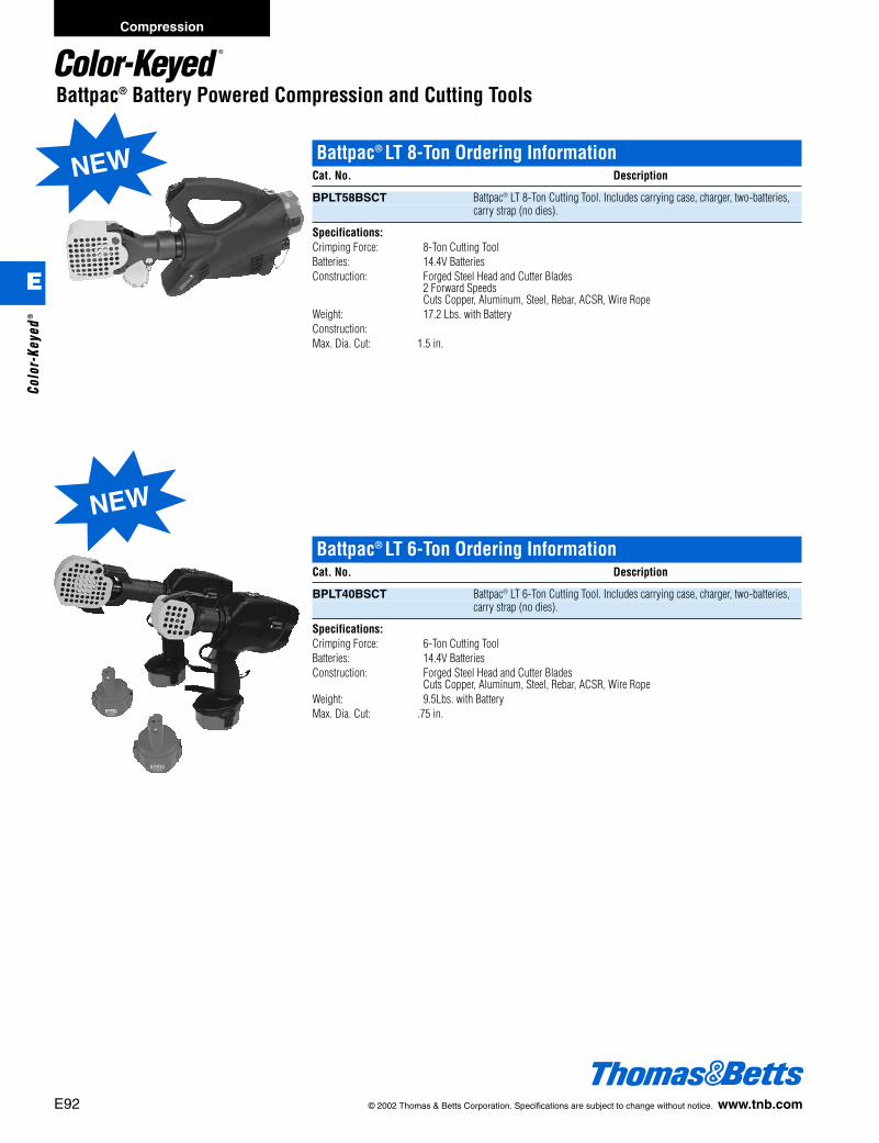
E92 © 2002 Thomas & Betts Corporation. Specifications are subject to change without notice. www.tnb.com
Compression
Battpac® LT 8-Ton Ordering InformationCat. No. Description
BPLT58BSCT Battpac® LT 8-Ton Cutting Tool. Includes carrying case, charger, two-batteries,carry strap (no dies).
Specifications:Crimping Force: 8-Ton Cutting ToolBatteries: 14.4V BatteriesConstruction: Forged Steel Head and Cutter Blades
2 Forward SpeedsCuts Copper, Aluminum, Steel, Rebar, ACSR, Wire Rope
Weight: 17.2 Lbs. with BatteryConstruction:Max. Dia. Cut: 1.5 in.
Battpac® LT 6-Ton Ordering InformationCat. No. Description
BPLT40BSCT Battpac® LT 6-Ton Cutting Tool. Includes carrying case, charger, two-batteries,carry strap (no dies).
Specifications:Crimping Force: 6-Ton Cutting ToolBatteries: 14.4V BatteriesConstruction: Forged Steel Head and Cutter Blades
Cuts Copper, Aluminum, Steel, Rebar, ACSR, Wire RopeWeight: 9.5Lbs. with BatteryMax. Dia. Cut: .75 in.
Battpac® Battery Powered Compression and Cutting Tools
NEW
NEW
E
Colo
r-Ke
yed®
412031.E01 CK 3/5 3/13/03 8:23 PM Page 92

© 2002 Thomas & Betts Corporation. Specifications are subject to change without notice. www.tnb.com E93
Compression
Battpac® LT Fast Cycle Cutting Tool Ordering InformationCat. No. Description
BPLT54BSCT Battpac® LT Fast Cycle Cutting Tool. Includes carrying case, charger, two-batteries, carry strap (no dies).
Specifications:Crimping Force: Fast Cycle Cutting ToolBatteries: 6.0V BatteriesConstruction: Cuts Copper, AluminumWeight: only 4.8 Lbs.Max. Dia. Cut: 2a in.; 750 kcmil Copper
Battpac® Battery Powered Compression and Cutting Tools
Battpac® LT 35-Ton Hydraulic Steel Punch Ordering InformationCat. No. Description
TBMHP-1 Battpac® LT 35-Ton Hydraulic Steel Punch. Includes case.
Specifications:Crimping Force: 35-Ton Hydraulic Steel PunchDies: Complete with 5 dies.Batteries: 6.0V BatteriesConstruction: Oval, Round, Square and Slotted DiesCapacity: d inch thick mild steel.Rated Operating Pressure: 10,000 PSI Operating from pump sourceWeight: only 4.8 Lbs.
NEW
NEW
E
Color-Keyed®
412031.E01 CK 3/5 3/13/03 8:23 PM Page 93

E94 © 2002 Thomas & Betts Corporation. Specifications are subject to change without notice. www.tnb.com
Compression
Connector Tools
FeaturesWide Compression Range• #8 through 600 kcmil copper lugs and splices.• #10 through 400 kcmil alum. lugs and splices.• 54705 through 54750 “C” taps.• CHT214-9 and CHT814-10 copper “H” taps.• Also accepts Blackburn® insert dies for OD58
tools.Lightweight DesignWeighs less than 7 lbs. including dies.Color-coded DiesEasy match with Thomas & Betts color-codedconnectors. Dies sold separately or as a set.Die code embossingInspectable crimp connectionsU.L./CSA CertifiedListed with Color-Keyed® or Blackburn® connec-tors from Thomas & Betts.5 Year Warranty against defects. Includes steelcarrying case which holds up to 15 die sets.
6-Ton Hydraulic Insulated HeadCat. No. Description
TBM6H
The TBM6H Remote Hydraulic Crimping Head is a lightweight but powerful compression tool. The TBM6H operates from any 10,000 psi hydraulic pump and crimps a wide range of compressionlugs, splices and taps, either copper or aluminum. The dies are interchangeable for the wire rangescovered and all include die code embossing to ease the inspection of the completed connection.
Output Force 6 tons nominalOperating Pressure: 10,000 PSI Nominal(Safety By-Pass on pump set at 9800 PSI)
Tool weight: 6d lbs. (without dies)Tool dimensions: 13d in. long, 3d in. wideTool carrying case includedDies are ordered as a set (2 pieces)Upper & lower dies are identical
TBM6H Application Information
Color-Keyed® Connector Dies
Connector Size Copper C TapTBM6H Hydraulic Head
Die Die Code ColorCopper Aluminum Cat. No.** Cat. No. No. Code
8 AWG 10 AWG 54705 6TON21 21 Red6 AWG 8 AWG 54710 6TON24 24 Blue4 AWG 6 AWG 54715 6TON29 29 Grey2 AWG 54720 6TON33 33 Brown1 AWG 4 AWG 54725 6TON37 37 Green
1/0 AWG 2 AWG 54730 6TON42 42H Pink2/0 AWG 1 AWG 54735 6TON45 45 Black/Gold3/0 AWG 1/0 AWG 54740 6TON50 50 Orange/Tan4/0 AWG 2/0 AWG 54745 6TON54 54H Purple/Olive
3/0 AWG 6TON60 60 Ruby250 kcmil 54750 6TON62 62 Yellow300 kcmil 4/0 AWG 6TON66 66 White350 kcmil 250 kcmil 6TON71 71H Red400 kcmil 300 kcmil 6TON76 76 Blue
925/24 6TON80 80 Black500 kcmil 350 kcmil 6TON87 87H Brown600 kcmil 400 kcmil 6TON94 94 Green
*Exception–Consult Connector Stuffer Sheets for Catalog No. series 61900, 61100 & 61300.**Consult Connector Stuffer Sheet for Wire Ranges.
Copper H-Tap Dies
H-Tap Cat. No. Color Code Die Cat. No.
CHT214-9 Brown 6TON71RCHT814-10 Green 6TON37R
Ordering Information
Cat. No. Description Std. Pkg.
TBM6H Remote 6 Ton 1Hydraulic Head
TBM6HD-1 Die Set 1for #8 thru500 kcmil
(6-TON 21-6-TON 87)
E
Colo
r-Ke
yed®
412031.E01 CK 3/5 3/13/03 8:23 PM Page 94
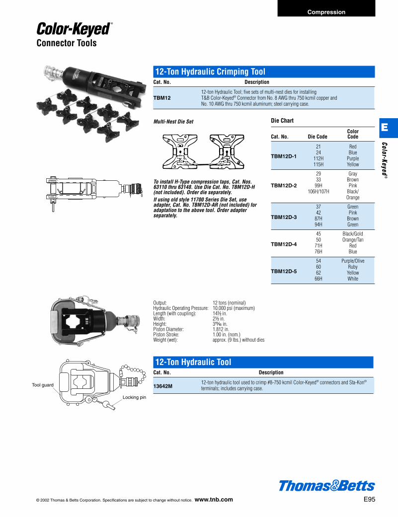
© 2002 Thomas & Betts Corporation. Specifications are subject to change without notice. www.tnb.com E95
Compression
Connector Tools
Die Chart
ColorCat. No. Die Code Code
21 Red
TBM12D-124 Blue
112H Purple115H Yellow
29 Gray33 Brown
TBM12D-2 99H Pink106H/107H Black/
Orange
37 Green
TBM12D-342 Pink
87H Brown94H Green
45 Black/Gold
TBM12D-450 Orange/Tan
71H Red76H Blue
54 Purple/Olive
TBM12D-560 Ruby62 Yellow
66H White
Multi-Nest Die Set
To install H-Type compression taps, Cat. Nos.63110 thru 63148. Use Die Cat. No. TBM12D-H(not included). Order die separately.If using old style 11700 Series Die Set, useadapter, Cat. No. TBM12D-AR (not included) foradaptation to the above tool. Order adapterseparately.
12-Ton Hydraulic Crimping ToolCat. No. Description
12-ton Hydraulic Tool; five sets of multi-nest dies for installing TBM12 T&B Color-Keyed® Connector from No. 8 AWG thru 750 kcmil copper and
No. 10 AWG thru 750 kcmil aluminum; steel carrying case.
Output: 12 tons (nominal)Hydraulic Operating Pressure: 10,000 psi (maximum)Length (with coupling): 14d in.Width: 2d in.Height: 3n in.Piston Diameter: 1.812 in.Piston Stroke: 1.00 in. (nom.)Weight (wet): approx. (9 lbs.) without dies
FORGED
STEEL
Tool guard
Locking pin
12-Ton Hydraulic ToolCat. No. Description
13642M12-ton hydraulic tool used to crimp #8-750 kcmil Color-Keyed® connectors and Sta-Kon®
terminals; includes carrying case.
E
Color-Keyed®
412031.E01 CK 3/5 3/13/03 8:23 PM Page 95
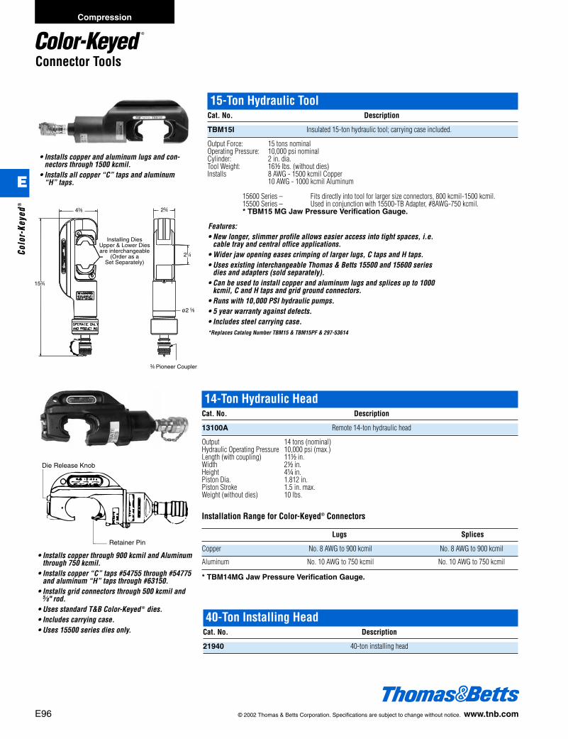
E96 © 2002 Thomas & Betts Corporation. Specifications are subject to change without notice. www.tnb.com
Compression
• Installs copper and aluminum lugs and con-nectors through 1500 kcmil.
• Installs all copper “C” taps and aluminum“H” taps.
15-Ton Hydraulic ToolCat. No. Description
TBM15I Insulated 15-ton hydraulic tool; carrying case included.
Output Force: 15 tons nominalOperating Pressure: 10,000 psi nominalCylinder: 2 in. dia.Tool Weight: 16d lbs. (without dies)Installs 8 AWG - 1500 kcmil Copper
10 AWG - 1000 kcmil Aluminum
14-Ton Hydraulic HeadCat. No. Description
13100A Remote 14-ton hydraulic head
Output 14 tons (nominal)Hydraulic Operating Pressure 10,000 psi (max.)Length (with coupling) 11d in.Width 2d in.Height 4b in.Piston Dia. 1.812 in.Piston Stroke 1.5 in. max.Weight (without dies) 10 lbs.
Installation Range for Color-Keyed® Connectors
Lugs Splices
Copper No. 8 AWG to 900 kcmil No. 8 AWG to 900 kcmil
Aluminum No. 10 AWG to 750 kcmil No. 10 AWG to 750 kcmil
* TBM14MG Jaw Pressure Verification Gauge.
• Installs copper through 900 kcmil and Aluminumthrough 750 kcmil.
• Installs copper “C” taps #54755 through #54775and aluminum “H” taps through #63150.
• Installs grid connectors through 500 kcmil and5⁄8" rod.
• Uses standard T&B Color-Keyed ® dies.• Includes carrying case.• Uses 15500 series dies only.
15600 Series – Fits directly into tool for larger size connectors, 800 kcmil-1500 kcmil.15500 Series – Used in conjunction with 15500-TB Adapter, #8AWG-750 kcmil.* TBM15 MG Jaw Pressure Verification Gauge.
Features:• New longer, slimmer profile allows easier access into tight spaces, i.e.
cable tray and central office applications.• Wider jaw opening eases crimping of larger lugs, C taps and H taps.• Uses existing interchangeable Thomas & Betts 15500 and 15600 series
dies and adapters (sold separately).• Can be used to install copper and aluminum lugs and splices up to 1000
kcmil, C and H taps and grid ground connectors.• Runs with 10,000 PSI hydraulic pumps.• 5 year warranty against defects.• Includes steel carrying case.*Replaces Catalog Number TBM15 & TBM15PF & 297-53614
Connector Tools
40-Ton Installing HeadCat. No. Description
21940 40-ton installing head
Die Release Knob
Retainer Pin
4c
15f
2f
2b
ø2 e
c Pioneer Coupler
Installing DiesUpper & Lower Diesare interchangeable
(Order as aSet Separately)
E
Colo
r-Ke
yed®
412031.E01 CK 3/5 3/13/03 8:23 PM Page 96
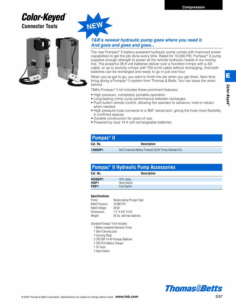
© 2002 Thomas & Betts Corporation. Specifications are subject to change without notice. www.tnb.com E97
Compression
NEWConnector Tools
T&B’s newest hydraulic pump goes where you need it. And goes and goes and goes...
The new Pumpac® II battery-powered hydraulic pump comes with improved powercapabilities to get the job done every time. Rated for 10,000 PSI, Pumpac® II pumpsupplies enough strength to power all the remote hydraulic heads in our toolingline. The powerful 28.8 volt batteries deliver over a hundred crimps with a 4/0cable, or up to seventy crimps with 750 kcmil cable without recharging. And bothbatteries can be recharged and ready to go in just one hour.When you’ve got to go, you want to finish the job when you get there. Next time,bring along a Pumpac® II system from Thomas & Betts. You can leave the wiresbehind.T&B’s Pumpac® II kit includes these prominent features:• High pressure, completely portable operation.• Long-lasting crimp cycle performance between recharges.• Push button remote control, allowing the operator to advance, hold or retract
when needed.• High pressure hose connects to a 360° swivel port, giving the hose more flexibility
in confined spaces.• Durable construction for years of use.• Powered by dual 14.4 volt rechargeable batteries.
Pumpac® IICat. No. Description
13950P1 Self Contained Battery Powered 28.8V Pump Standard Kit.
Pumpac® II Hydraulic Pump AccessoriesCat. No. Description
HOSEP1 10 ft. HoseHSP1 Hand SwitchFSP1 Foot Switch
SpecificationsPump: Reciprocating Plunger TypeRated Pressure: 10,000 PSIRated Voltage: 28.8VDimensions: 7.5” X 9.8” X 6.9”Weight: 35 lbs. with two batteries
Standard Pumpac® II kit includes:1 Battery-powered Hydraulic Pump1 Steel Carrying case1 Carrying Strap2 CRCTBP 14.4V Pumpac Batteries1 CRCTCH Battery Charger1 10' Hose1 Hand Switch
E
Color-Keyed®
412031.E01 CK 3/5 3/13/03 8:23 PM Page 97
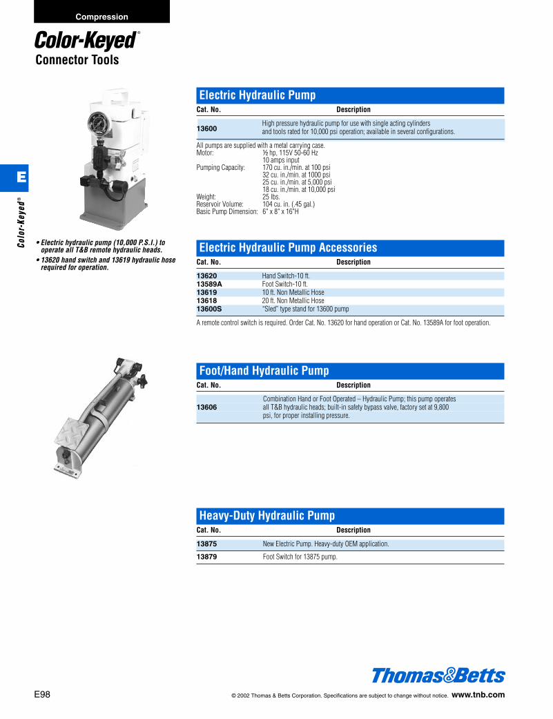
E98 © 2002 Thomas & Betts Corporation. Specifications are subject to change without notice. www.tnb.com
Compression
Connector Tools
• Electric hydraulic pump (10,000 P.S.I.) tooperate all T&B remote hydraulic heads.
• 13620 hand switch and 13619 hydraulic hoserequired for operation.
Electric Hydraulic PumpCat. No. Description
13600High pressure hydraulic pump for use with single acting cylinders and tools rated for 10,000 psi operation; available in several configurations.
All pumps are supplied with a metal carrying case.Motor: d hp, 115V 50-60 Hz
10 amps inputPumping Capacity: 170 cu. in./min. at 100 psi
32 cu. in./min. at 1000 psi25 cu. in./min. at 5,000 psi18 cu. in./min. at 10,000 psi
Weight: 25 lbs.Reservoir Volume: 104 cu. in. (.45 gal.)Basic Pump Dimension: 6" x 8" x 16"H
Electric Hydraulic Pump AccessoriesCat. No. Description
13620 Hand Switch-10 ft.13589A Foot Switch-10 ft.13619 10 ft. Non Metallic Hose13618 20 ft. Non Metallic Hose13600S “Sled” type stand for 13600 pump
A remote control switch is required. Order Cat. No. 13620 for hand operation or Cat. No. 13589A for foot operation.
Foot/Hand Hydraulic PumpCat. No. Description
Combination Hand or Foot Operated – Hydraulic Pump; this pump operates 13606 all T&B hydraulic heads; built-in safety bypass valve, factory set at 9,800
psi, for proper installing pressure.
Heavy-Duty Hydraulic PumpCat. No. Description
13875 New Electric Pump. Heavy-duty OEM application.
13879 Foot Switch for 13875 pump.
E
Colo
r-Ke
yed®
412031.E01 CK 3/5 3/13/03 8:23 PM Page 98

© 2002 Thomas & Betts Corporation. Specifications are subject to change without notice. www.tnb.com E99
Compression
Connector Tools
Electric Hydraulic Pump with Shure-Stake® ControlCat. No. Description
Shure-Stake® electric hydraulic pump has same features as 13600, but
13610Aincludes the Shure-Stake® control mechanism; prevents under crimping. (pump pressure must reach 9,800 psi before recycling); requires hand or foot control; order switch and hose separately.
Motor Rating: d HP, 115V, 50-60 Hz, 12.5 ampsMaximum Pressure: 10,000 psiPumping Capacity: 170 cu. in./min. at 100 psi
32 cu. in./min. at 1000 psi25 cu. in./min. at 5000 psi18 cu. in./min. at 10,000 psi
Reservoir Volume: 104 cu. in. (.45 gal.)Basic Pump Dimension: 8d" x 10d" x 16"HWeight: 35 lbs.Application: Pump is suitable for use with all T&B hydraulic tools
Electric Hydraulic Pump AccessoriesCat. No. Description
13611 Hand Switch-10 ft.13612 Foot Switch-10 ft.13797 In line hydraulic pressure inspection gauge with male and female pioneer type coupler.
A remote control switch is required to operate this unit. Use either a #13611 (hand) or #13612 (foot) switch.
Hydraulic OilCat. No. Description
21061 Hydraulic Oil
Disconnect CouplersCat. No. Description
13798 Male pioneer quick disconnect coupler.13799 Female pioneer quick disconnect coupler.
Electric Hydraulic PumpStd.
Cat. No. Description Pkg.
13810 Electric hydraulic pump, 10000 psi with Shure-Stake® mechanism feature; 1this is a heavy duty OEM pump with high flow rate; 115V, 60Hz, 1d HP, 23 Amps; requires hand or foot control
E
Color-Keyed®
412031.E01 CK 3/5 3/13/03 8:23 PM Page 99
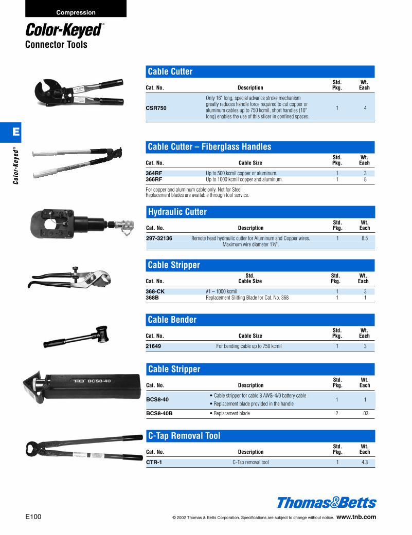
E100 © 2002 Thomas & Betts Corporation. Specifications are subject to change without notice. www.tnb.com
Compression
Connector Tools
Cable CutterStd. Wt.
Cat. No. Description Pkg. Each
Only 16" long, special advance stroke mechanism
CSR750greatly reduces handle force required to cut copper or
1 4aluminum cables up to 750 kcmil, short handles (10" long) enables the use of this slicer in confined spaces.
Cable Cutter – Fiberglass HandlesStd. Wt.
Cat. No. Cable Size Pkg. Each
364RF Up to 500 kcmil copper or aluminum. 1 3366RF Up to 1000 kcmil copper and aluminum. 1 8
For copper and aluminum cable only. Not for Steel.Replacement blades are available through tool service.
Cable StripperStd. Wt.
Cat. No. Description Pkg. Each
BCS8-40• Cable stripper for cable 8 AWG-4/0 battery cable
1 1• Replacement blade provided in the handle
BCS8-40B • Replacement blade 2 .03
C-Tap Removal ToolStd. Wt.
Cat. No. Description Pkg. Each
CTR-1 C-Tap removal tool 1 4.3
Cable StripperStd. Std. Wt.
Cat. No. Cable Size Pkg. Each
368-CK #1 – 1000 kcmil 1 3368B Replacement Slitting Blade for Cat. No. 368 1 1
Cable BenderStd. Wt.
Cat. No. Cable Size Pkg. Each
21649 For bending cable up to 750 kcmil 1 3
Hydraulic CutterStd. Wt.
Cat. No. Description Pkg. Each
297-32136 Remote head hydraulic cutter for Aluminum and Copper wires. 1 8.5Maximum wire diameter 1d".
E
Colo
r-Ke
yed®
412031.E01 CK 3/5 3/13/03 8:23 PM Page 100
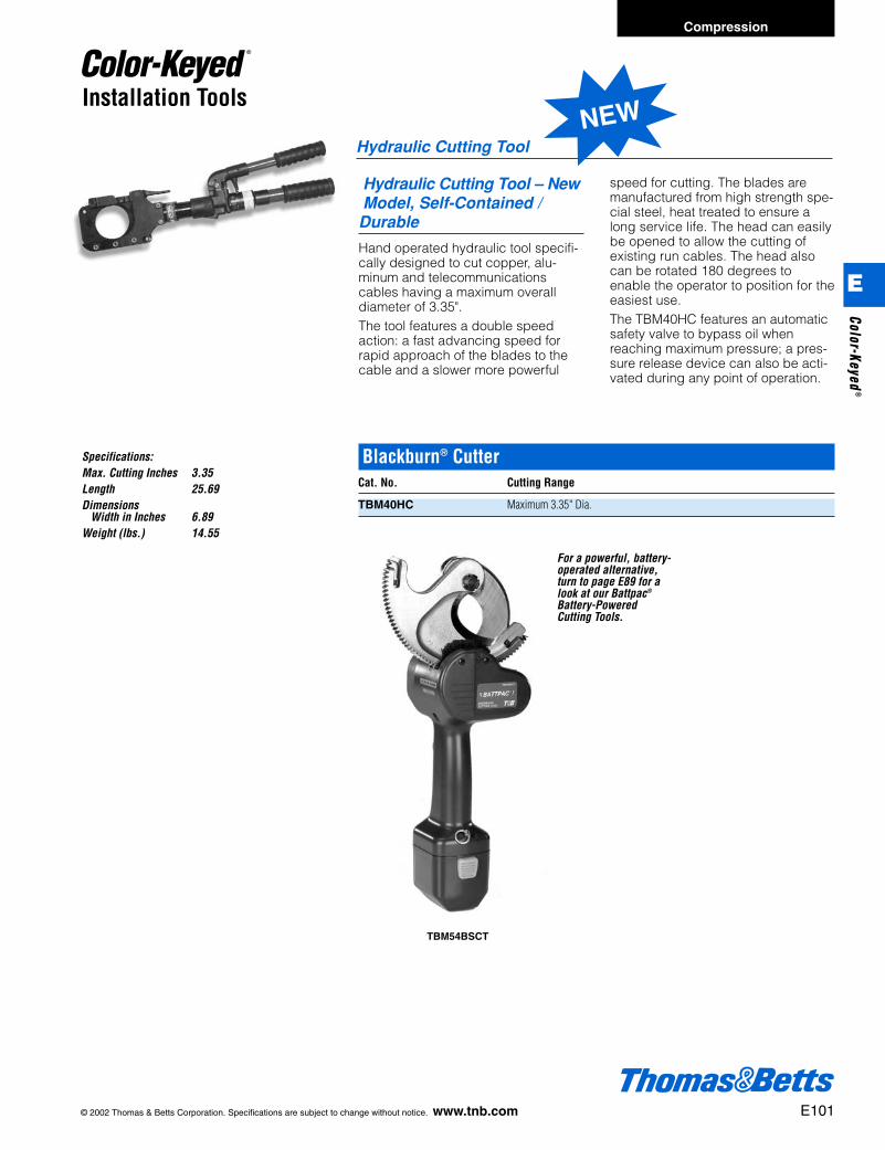
© 2002 Thomas & Betts Corporation. Specifications are subject to change without notice. www.tnb.com E101
Compression
Installation Tools
Hydraulic Cutting Tool
Blackburn® CutterCat. No. Cutting Range
TBM40HC Maximum 3.35" Dia.
Hydraulic Cutting Tool – NewModel, Self-Contained / Durable
Hand operated hydraulic tool specifi-cally designed to cut copper, alu-minum and telecommunicationscables having a maximum overalldiameter of 3.35".The tool features a double speedaction: a fast advancing speed forrapid approach of the blades to thecable and a slower more powerful
speed for cutting. The blades aremanufactured from high strength spe-cial steel, heat treated to ensure along service life. The head can easilybe opened to allow the cutting ofexisting run cables. The head alsocan be rotated 180 degrees toenable the operator to position for theeasiest use.The TBM40HC features an automaticsafety valve to bypass oil whenreaching maximum pressure; a pres-sure release device can also be acti-vated during any point of operation.
Specifications:Max. Cutting Inches 3.35Length 25.69Dimensions
Width in Inches 6.89Weight (lbs.) 14.55
NEW
E
Color-Keyed®
For a powerful, battery-operated alternative,turn to page E89 for alook at our Battpac®
Battery-PoweredCutting Tools.
TBM54BSCT
412031.E01 CK 3/5 3/13/03 8:23 PM Page 101

E102 © 2002 Thomas & Betts Corporation. Specifications are subject to change without notice. www.tnb.com
Compression
E
Colo
r-Ke
yed®
Installation Tools
For installing ground rods, there’s nosafer, simpler or more efffective toolthan the Thomas & Betts Ground RodDriver. It can be used on all types ofground rods including copper-bond-ed, galvanized and stainless steel.Integral inserts prevent the driverfrom slipping off the rod near groundlevel. The inserts are e" and f", andare interchangeable with the standarddriver body. The convenient retainingcollar holds the insert in the tool whennot in use.Thomas & Betts Ground Rod Drivershave a heavy-duty steel cons-tructionthat allows maximum force for drivingground rods, while the efficientdesign ensures that minimal lifting
force is required. The ground rod endis designed for high impact applica-tions to ensure quality connections.• Unique design allows installation of
10-footrods from ground level.• Heavy-duty steel construction.• Ergonomic grip provides ease and
comfort with increased safty.• Complete with interchangeable
parts that are range-taking for differ-ent diameter ground rods.
• Two interchangeable inserts allowthe same tool to be used with allsizes of rods.
• Completely self-contained and easyto store.
Photo includes ground rod driver and insert
MaximumWeight Rod Diameter Pack
Cat. No. Description (lb) (in.) Quantity
TBRD58 5' Ground Rod Driver 25 .63 1with e" insert
TBRD34 5' Ground Rod Driver 25 .75 1with f" insert
TBS58 Replacement e" insert 4 .63 1TBS58 Replacement f" insert 4 .75 1
Ground Rod Driver
NEW
412031.E01 CK 3/5 3/13/03 8:23 PM Page 102

© 2002 Thomas & Betts Corporation. Specifications are subject to change without notice. www.tnb.com E103
Compression
E
Color-Keyed®
Sealants and Lubricants
• For removing oxides from conductor surfaces• Easy grip handle with glove guard to prevent
rubber glove puncture• Long life brushes can be rotated and are
replaceable• Handle and guard coated with durable non-
conductive plastic
Type WW – Wire Bristle BrushCat. No. Description
WWB1 Complete Brush with HandleWRB1 Wire Element Only, Pair
Silicone lubricant
• Seals around junction boxes, flashings, ser-vice mast entries, service cable entries andcountless other applications
• Easy to use, forms around irregular surfacesand configurations
• Highly resistant to cracking, drying andshrinking
• Cuts and trims easily• Can be painted immediately after application• Grey color• No unpleasant odor• +20°F to 212°F workable temperature range• -40°F to 250°F service temperature range• Contains no asbestos
Type DX – Duct SealCat. No. Size
DX-1 1 lb. SlugDX-5 5 – 1 lb. SlugsDX-5S 5 lb. Slug
U.L. Classified R13335
Silicone Lubricant for High Voltage Electrical WorkCat. No. Size Std. Pkg.
2012 2 grams 250 tubes2015 5 grams 100 tubesSL5 5 oz./142 grams 12 tubes
®
412031.E01 CK 3/5 3/13/03 8:23 PM Page 103
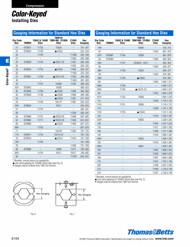
E104 © 2002 Thomas & Betts Corporation. Specifications are subject to change without notice. www.tnb.com
Compression
Installing Dies
Gauging Information for Standard Hex DiesTBM15I
Die Code 13642 & 13400 TBM14M, 13100A 21940 HexNos. TBM6H Dies Dies Dies Gauging
21 6TON21 11732 15520 – .191-.20724 6TON24 11733 ▲15522 – .222-.23426 11754 – *11400 .262-.26827 – – 11330 .262-.26829 6TON29 11734 ▲15527-CK 11401 .282-.29432 – – 11332 .329-.33533 6TON33 11735 ▲15528 11402 .326-.33735 – – *11403 .353-.35937 6TON37 11736 ▲15513-CK 11333 .369-.38340 – – *11404 .397-.40342 11737 15508F 11334 .409-.423
42H 6TON42 – 15508 – .409-.42345 6TON45 11738 ▲15526 11405 .445-.45950 6TON50 11739 ▲15530 11406 .494-.50652 – ▲15529 11361 .511-.52954 11740 15511F 11407 .535-.553
54H 6TON54 – 15511 – .535-.55357 11770 – – .585-.59158 – – 11338 .585-.59160 6TON60 11741 ▲15532-CK 11408 .587-.60562 6TON62 11771 ▲15510-CK 11340 .613-.63166 6TON66 – ▲15534 11409 .657-.675
66H 11742 – – .657-.67571 – 15514F 11363 .707-.725
71H 6TON71 11743 15514-CK – .707-.72576 6TON76 – ▲15512 11410 .751-.769
76H 11744 – – .751-.76978 – – 11306 .751-.76980 6TON80 – 15606 11411 .790-.802
80H 11745 15517 15517 .790-.80283 – – *11370 .825-.831
* Obsolete, consult factory for availability.▲ Use same gauging for 15500F Series dies (see Fig. 2).• Gauges may be ordered from T&B Tool Service.
Hex Gauging Hex Gauging
Fig. 2 Fig. 1
Gauging Information for Standard Hex DiesTBM15I
Die Code 13642 & 13400 TBM14M, 13100A 21940 HexNos. TBM6H Dies Dies Dies Gauging
74H – 15604 – .733-.75187 – – 11423 .861-.879
87H 6TON87 11746 15506 – .861-.87994 6TON94 – – 11364 .935-.953
94H 11747 15536CK, 15611 – .935-.95396 – – 11304 .959-.977
96H 11758 15503 – .959-.97799 – – 11424 .979-.997
99H 11748 ▲15505 – .979-.997100 – – 11365 1.005-1.011
106A 11759 – – 1.049-1.071106H 11749 ▲15515-CK – 1.049-1.071107 – – 11425 1.064-1.076
107H 11750 15608 – 1.064-1.076112 – – 11426 1.118-1.131
112H 11751 15609 – 1.118-1.131115 – – 11308 1.141-1.163
115H 11753 ▲15504 – 1.141-1.163125 – – 11416 1.239-1.261
125H – 15603 – 1.239-1.261126 – – 11443 1.247-1.253130 – – 11417 1.299-1.305138 – – 11366 1.377-1.383140 – – 11418 1.369-1.391
140H – 15602 – 1.369-1.391150 – – 11419 1.459-1.481
150H – 15601 – 1.459-1.481160 – – 11442 1.609-1.615161 – – 11420 1.609-1.615168 – – 11447 1.684-1.690175 – – 11421 1.752-1.744204 – – 11448 2.037-2.043212 – – 11449 2.120-2.126214 – – 11337 2.140-2.146
* Obsolete, consult factory for availability.▲ Use same gauging for 15500F Series dies (see Fig. 2).• Gauges may be ordered from T&B Tool Service.
E
Colo
r-Ke
yed®
412031.E01 CK 3/5 3/13/03 8:23 PM Page 104
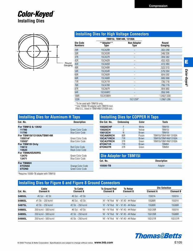
© 2002 Thomas & Betts Corporation. Specifications are subject to change without notice. www.tnb.com E105
Compression
Installing Dies
Installing Dies for High Voltage ConnectorsTBM15I, TBM14M, 13100A
Die Code **Adapter** Non-Adapter RoundNumbers Type Type Gauging
29R 15CA29R – .302/.29033R 15CA33R – .348/.33637R 15CA37R – .394/.38242R 15CA42R – .432/.42045R 15CA45R – .472/.46049R 15CA49R – .522/.51054R 15CA54R – .576/.56460R 15CA60R – .604/.59266R 15CA66R – .680/.66871R 15CA71R – .730/.71876R 15CA76R – .790/.77887R 15CA87R – .904/.89294R 15CA94R† – .958/.946106R 15CA106R† – 1.042/1.030125R – 15C125R* 1.298/1.286
**To be used with TBM15I only.**Use 15500-TB adapter with TBM15I tool.†Not U.L. listed in TBM14M/13100A tool.
Installing Dies for Figure 6 and Figure 8 Ground ConnectorsCable To Cable To Ground Rod To Rebar Die Selection
Cat. No. Element A Element B Element B Element B Element A Element B
54855L #6 Sol. - #2 Str. #6 Sol. - #2 Str. – – 15501A 15501A
54865L #1 Str. - 250 kcmil #6 Sol. - #2 Str. d" - e" Rod c" - d" #3 - #4 Rebar 15G86R 15501A
54875L #2 Str. - 250 kcmil #2 Str. - 250 kcmil d" - e" Rod c" - d" #3 - #4 Rebar 15G86R 15G86R
54885L 250 kcmil - 500 kcmil #6 Sol. - #2 Str. e" - f" Rod e" - f" #3 - #4 Rebar 15G126R 15501A
54895L 250 kcmil - 500 kcmil #2 Str. - 250 kcmil e" - f" Rod e" - f" #3 - #4 Rebar 15G126R 15G86R
54900L 250 kcmil - 500 kcmil #2 Str. - 250 kcmil e" - f" Rod e" - f" #3 - #4 Rebar 15G121R 15G121R
RoundGauging
Installing Dies for COPPER H TapsDie Cat. No. Embossing Color Tools
15620CHF F White TBM15I15620CH Z Yellow TBM15I15612CH N Brown TBM15I15CA80RCH 80R Purple TBM15I/TBM14M 13100A15CA71RCH 71R Brown TBM15I/TBM14M/13100A15CA37RCH 37R Green TBM15I/TBM14M/13100A6TON71R 71R Brown TBM6H6TON37R 37R Green TBM6H
Die Adapter for TBM15ICat. No. Description
15500-TB Adapter
Installing Dies for Aluminum H TapsCat. No. Description
For TBM12 & 1364211780 Green Color Code11790 Blue Color Code
For TBM15I/13100A/TBM14M15501A* Green Color Code15502* Blue Color Code
For TBM15I Only15612 Red Color Code15620 Black Color Code
For TBM6/6S/60RS13470 Green Color Code13471 Blue Color Code
For TBM6H6TON50 Orange Color Code6TON0 Green Color Code
*Requires 15500-TB adapter with TBM15I
E
Color-Keyed®
412031.E01 CK 3/5 3/13/03 8:23 PM Page 105
E106 © 2002 Thomas & Betts Corporation. Specifications are subject to change without notice. www.tnb.com
Compression
Installing Dies
Cable Slicing Die Sets
Cuts copper and aluminum insulated cable sizes from #8 AWG through 500 kcmil.Produces clean, squared end cut which eliminates extra trimming of conductorstrands.
Cat. No. Maximum Cable Size Tools
BY55 2/0 TBM6H and TBM6BSCR
40C 4/0 TBM14M AND 13100A AND TBM14BSCR
156CS 500 kcmil TBM15I AND TBM15BSCR
E
Colo
r-Ke
yed®
412031.E01 CK 3/5 3/13/03 8:23 PM Page 106
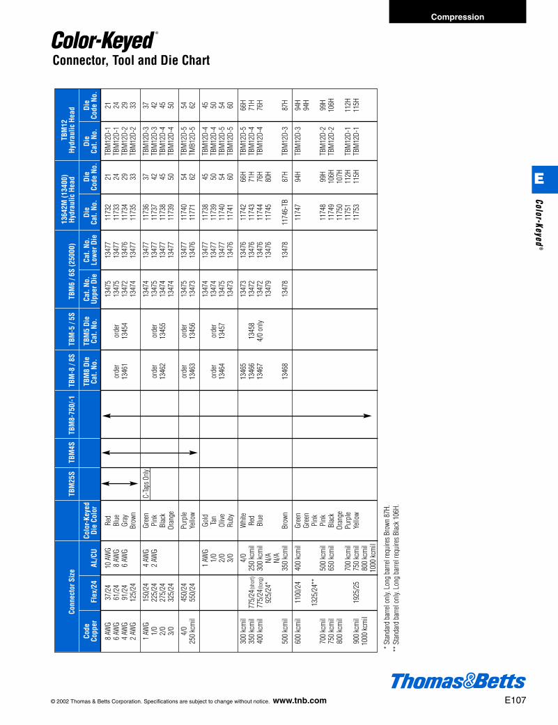
© 2002 Thomas & Betts Corporation. Specifications are subject to change without notice. www.tnb.com E107
Compression
Connector, Tool and Die Chart13
642M
(134
00)
TBM
12
Conn
ecto
r Siz
eTB
M25
STB
M4S
TBM
8-75
0/-1
TBM
-8 /
8STB
M-5
/ 5S
TBM
6 / 6
S (2
5000
)Hy
drau
lic H
ead
Hydr
aulic
Hea
d
Code
Colo
r-Ke
yed
TBM
8 Di
eTB
M5
Die
Cat.
No.
Cat.
No.
Die
Die
Die
Di
e Co
pper
Flex
/24
AL/C
UDi
e Co
lor
Cat.
No.
Cat.
No.
Uppe
r Die
Low
er D
ieCa
t. No
.Co
de N
o.Ca
t. No
.Co
de N
o.
8 AW
G37
/24
10 A
WG
Red
1347
513
477
1173
221
TBM
12D-
121
6 AW
G61
/24
8 AW
GBl
ueor
der
orde
r13
475
1347
711
733
24TB
M12
D-1
244
AWG
91/2
46
AWG
Gray
1346
113
454
1347
213
476
1173
429
TBM
12D-
229
2 AW
G12
5/24
Brow
n13
474
1347
711
735
33TB
M12
D-2
33
1 AW
G15
0/24
4 AW
GGr
een
C-Ta
ps O
nly13
474
1347
711
736
37TB
M12
D-3
371/
022
5/24
2 AW
GPi
nkor
der
orde
r13
475
1347
711
737
42TB
M12
D-3
422/
027
5/24
Blac
k13
462
1345
513
474
1347
711
738
45TB
M12
D-4
453/
032
5/24
Oran
ge13
474
1347
711
739
50TB
M12
D-4
50
4/0
450/
24Pu
rple
orde
ror
der
1347
513
477
1174
054
TBM
12D-
554
250
kcm
il55
0/24
Yello
w13
463
1345
613
473
1347
611
771
62TM
B12D
-562
1 AW
GGo
ld13
474
1347
711
738
45TB
M12
D-4
451/
0Ta
nor
der
orde
r13
474
1347
711
739
50TB
M12
D-4
502/
0Ol
ive13
464
1345
713
475
1347
711
740
54TB
M12
D-5
543/
0Ru
by13
473
1347
611
741
60TB
M12
D-5
60
300
kcm
il4/
0W
hite
1346
513
473
1347
611
742
66H
TBM
12D-
566
H35
0 kc
mil
775/
24(s
hort)
250
kcm
ilRe
d13
466
1345
813
472
1347
611
743
71H
TBM
12D-
471
H40
0 kc
mil
775/
24(lo
ng)
300
kcm
ilBl
ue13
467
4/0
only
1347
213
476
1174
476
HTB
M12
D-4
76H
925/
24*
N/A
1347
913
476
1174
580
HN/
A50
0 kc
mil
350
kcm
ilBr
own
1346
813
478
1347
811
746-
TB87
HTB
M12
D-3
87H
600
kcm
il11
00/2
440
0 kc
mil
Gree
n11
747
94H
TBM
12D-
394
HGr
een
94H
1325
/24*
*Pi
nk70
0 kc
mil
500
kcm
ilPi
nk11
748
99H
TBM
12D-
299
H75
0 kc
mil
650
kcm
ilBl
ack
1174
910
6HTB
M12
D-2
106H
800
kcm
ilOr
ange
1175
010
7H70
0 kc
mil
Purp
le11
751
112H
TBM
12D-
111
2H90
0 kc
mil
1925
/25
750
kcm
ilYe
llow
1175
311
5HTB
M12
D-1
115H
1000
kcm
il80
0 kc
mil
1000
kcm
il
** S
tanda
rd b
arre
l onl
y. Lo
ng b
arre
l req
uire
s Bro
wn 8
7H.
** S
tanda
rd b
arre
l onl
y. Lo
ng b
arre
l req
uire
s Blac
k 106
H.
E
Color-Keyed®
412031.E01 CK 3/5 3/13/03 8:23 PM Page 107
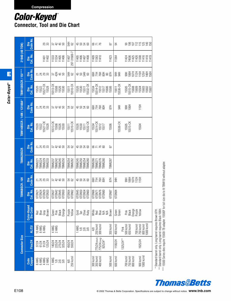
E108 © 2002 Thomas & Betts Corporation. Specifications are subject to change without notice. www.tnb.com
Compression
E
Colo
r-Ke
yed®
Connector, Tool and Die ChartCo
nnec
tor S
ize
TBM
6BSC
R / 6
HTB
M62
BSCR
TBM
14BS
CR /
14M
/ 13
100A
*TB
M15
BSCR
/ 15
I***
2194
0 (4
0 TO
N)
Code
Colo
r-Ke
yed
Die
Die
Die
Die
Die
Die
Die
Die
Die
Die
Copp
erFl
ex/2
4AL
/CU
Die
Colo
rCa
t. No
.Co
de N
o.Ca
t. No
.Co
de N
o.Ca
t. No
.Co
de N
o.Ca
t. No
.Co
de N
o.Ca
t. No
.Co
de N
o.
8 AW
G37
/24
10 A
WG
Red
6TON
2121
TBM
6221
2115
520
2115
520
216
AWG
61/2
48
AWG
Blue
6TON
2424
TBM
6224
2415
522
2415
522
244
AWG
91/2
46
AWG
Gray
6TON
2929
TBM
6229
2915
527-
CK29
1552
7-CK
2911
401
292
AWG
125/
24Br
own
6TON
3333
TBM
6233
3315
528
3315
528
3311
402
33
1 AW
G14
0/24
4 AW
GGr
een
6TON
3737
TBM
6237
3715
513-
CK37
1551
3-CK
3711
333
371/
022
5/24
2 AW
GPi
nk6T
ON42
42TB
M62
4242
1550
842
1550
842
H11
334
422/
027
5/24
Blac
k6T
ON45
45TB
M62
4545
1552
645
1552
645
1140
545
3/0
325/
24Or
ange
6TON
5050
TBM
6250
5015
530
5015
530
5011
406
50
4/0
450/
24Pu
rple
6TON
5454
TBM
6254
5415
511
5415
511
54H
1140
754
H25
0 kc
mil
550/
24Ye
llow
6TON
6262
TBM
6262
6215
510-
CK62
1551
0-CK
6229
7-31
669-
762
1 AW
GGo
ld6T
ON45
45TB
M62
4545
1552
645
1552
645
1140
545
1/0
Tan
6TON
5050
TBM
6250
5015
530
5015
530
5011
406
502/
0Ol
ive6T
ON54
54TB
M62
5454
1551
154
1551
154
H11
407
543/
0Ru
by6T
ON60
60TB
M62
6060
1553
2-CK
6015
532-
CK60
1140
860
300
kcm
il4/
0W
hite
6TON
6666
HTB
M62
6666
1553
466
H15
534
66H
1140
966
350
kcm
il77
5/24
(sho
rt)25
0 kc
mil
Red
6TON
7171
HTB
M62
7171
1551
4-CK
71H
1551
4-CK
71H
1136
371
400
kcm
il77
5/24
(long
)30
0 kc
mil
Blue
6TON
7676
HTB
M62
7676
1551
276
H15
512
76H
1141
076
925/
24*
N/A
6TON
8080
HTB
M62
8080
1551
780
H15
517
80H
N/A
1560
680
500
kcm
il35
0 kc
mil
Brow
n6T
ON87
87H
TBM
6287
8715
506
87H
1550
687
H11
423
87
600
kcm
il11
00/2
440
0 kc
mil
Gree
n6T
ON94
94H
1561
194
H11
364
94Gr
een
1553
6-CK
94H
1553
6-CK
94H
1325
/24*
*Pi
nk70
0 kc
mil
500
kcm
ilPi
nk99
H15
505
99H
1550
599
H11
424
9975
0 kc
mil
650
kcm
ilBl
ack
106H
1551
5-CK
106H
1551
5-CK
106H
7450
610
680
0 kc
mil
Oran
ge10
7H15
608
107H
1142
510
770
0 kc
mil
Purp
le11
2H15
609
112H
1142
611
290
0 kc
mil
1925
/24
750
kcm
ilYe
llow
115H
1550
411
5H15
504
115H
1130
811
510
00 kc
mil
800
kcm
il15
603
125H
1141
612
510
00 kc
mil
1560
214
0H11
418
140
1560
115
0H11
419
150
*** S
tanda
rd b
arre
l onl
y. Lo
ng b
arre
l req
uire
s Bro
wn 8
7H.
*** S
tanda
rd b
arre
l onl
y. Lo
ng b
arre
l req
uire
s Blac
k 106
H.**
* 155
00 S
eries
dies
requ
ire 1
5500
-TB
adap
ter. 1
5500
F fo
r ful
l size
die
to fi
t TBM
15I w
ithou
t ada
pter.
412031.E01 CK 3/5 3/13/03 8:23 PM Page 108

© 2002 Thomas & Betts Corporation. Specifications are subject to change without notice. www.tnb.com E109
Compression
E
Color-Keyed®
Cond
ucto
r Siz
e
Code
Cab
le (F
lex
Cabl
e)In
stal
latio
n
# of
Di
e St
rip
Insu
latin
g M
ain
Bran
ch 1
Bran
ch 2
Bran
ch 3
H-Ta
pCo
lor
DIE
TOOL
crim
psEm
boss
ing
Leng
thCo
ver
8-14
(8-1
4)8-
14 (8
-14)
––
CHT8
14-1
0Gr
een
15CA
37RC
H*Gr
oup
11
37R
d"
HTC2
S
2-6
Str /
Sol
(2-8
)2-
6 St
r / S
ol (2
-8)
8-14
(8-1
4)8-
14 (8
-14)
CHT2
14-9
Brow
n15
CA71
RCH*
Grou
p 1
171
Rg
"
250-
2 (4
/0-2
)8-
14 (8
-14)
8-14
(8-1
4)–
CHT2
5021
4-8
Purp
le15
CA80
RCH*
Grou
p 2
180
R1a
"HT
C40
250-
2 (4
/0-2
)2-
6 St
r / S
ol (2
-8)
8-14
(8-1
4)–
CHT2
5014
-7Pu
rple
15CA
80RC
H*Gr
oup
21
80R
1a"
250-
2 (4
/0-2
)25
0-2
(4/0
-2)
––
CHT2
502-
6Pu
rple
15CA
80RC
H*Gr
oup
21
80R
m"
500-
4/0
(350
-4/0
)25
0-1/
0 (4
/0-1
/0)
1 St
r 2-6
(1-8
)8-
14 (8
-14)
CHT5
0010
-5Br
own
1561
2CH
Grou
p 2
2N
1a"
500-
4/0
(350
-4/0
)50
0-4/
0 (3
50-4
/0)
––
CHT5
0040
-4Br
own
1561
2CH
Grou
p 2
2N
1a"
750-
350
(550
-500
)4/
0-1/
0 (2
50-1
/0)
1 St
r 2-6
(1-8
)2-
14 (2
-14)
CHT7
5010
-3Ye
llow
1562
0CH
Grou
p 2
1Z
1a"
HTC5
00
750-
350
(550
-500
)75
0-35
0 (5
50-3
50)
––
CHT7
5035
0-2
Yello
w15
620C
HGr
oup
21
Z1c
"
750
(750
-500
)35
0-4/
0 ST
R &
FLEX
––
CHT7
5040
-11
Yello
w15
620C
HGr
oup
21
Z1a
"
(750
-500
) (75
0)(7
50-5
00) (
350)
––
CHT7
5035
0-1F
Whi
te15
620C
HFGr
oup
21
F1a
"HT
C100
0
** R
equi
res o
ptio
nal a
dapt
er 1
5500
-TB
when
use
d wi
th h
ydra
ulic
head
TBM
15I a
nd T
BM15
BSCR
Grou
p 1
= TB
M15
I, TB
M15
BSCR
, TBM
14M
, TBM
14BS
CR, 1
3100
AGr
oup
2 =
TBM
15I,
TBM
15BS
CR
Connector, Tool and Die Chart For Copper H-Taps
412031.E01 CK 3/5 3/13/03 8:23 PM Page 109

E110 © 2002 Thomas & Betts Corporation. Specifications are subject to change without notice. www.tnb.com
Compression
E
Colo
r-Ke
yed®
Connector, Tool and Die Chart For Standard C-TapsCO
DE W
IRE
COM
B. C
IR. A
REA
RANG
EGr
oup
1TB
M62
BSCR
SMAR
T To
olGr
oup
2Gr
oup
3IN
SULA
TION
CHO
ICE
Mai
nBr
anch
1C-
Tap
Colo
rDI
EDI
EDI
EAD
HESI
VESH
RINK
TUB
ING
1214
5470
5Re
d6T
ON21
TBM
6221
–
1416
1010
5471
0Bl
ue6T
ON24
TBM
6224
HS12
-68
12
610
,12
5471
5Gr
ay6T
ON29
TBM
6229
–
88,
10,1
2
4 OR
58,
10,
12
5472
0Br
own
6TON
33TB
M62
33TB
M8-
750C
20
66,
8
36,
8, 1
0, 1
2 **
*54
725
Gree
n6T
ON37
TBM
6237
TBM
8-75
0C25
30
4 OR
56,
5HS
6-1
26,
8, 1
0, 1
254
730
Pink
6TON
42TB
M62
42TB
M8-
750C
2530
AC5X
3
35
43
14,
5, 6
, 8, 1
0, 1
254
735
Blac
k6T
ON45
TBM
6245
TBM
8-75
0C35
40
24,
5
33,
4
1/0
4, 5
, 6, 8
, 10,
12
5474
0Or
ange
6TON
50TB
M62
50TB
M8-
750C
3540
13,
4
22,
3HS
4-30
2/0
3, 4
, 5, 6
, 8, 1
0, 1
254
745
Purp
le6T
ON54
TBM
6254
TBM
8-75
0C45
50
1/0
2, 3
11,
3
3/0
2, 3
, 4, 5
, 6, 8
, 10,
12
5475
0Ye
llow
6TON
62TB
M62
62TB
M8-
750C
4550
2/0
1, 2
1/0
1/0,
1
*** W
hen
usin
g 3
AWG
on m
ain an
d 12
AW
G on
bra
nch
with
smar
t too
ls an
d di
es, 1
2 AW
G wi
re m
ust b
e dou
bled
(hair
-pin
ned)
and
plac
ed o
n br
anch
for c
rimpi
ngGr
oup
1 =
TBM
6H /
TBM
6BSC
RGr
oup
2 =
TBM
25S,
TBM
21E
and
requ
ire 2
com
pres
sions
with
in ea
ch cr
imp
area
Grou
p 3
= TB
M5
/ 5S,
TBM
6 / 6
S, T
BM8
/ 8S,
TBM
6H an
d re
quire
1 co
mpr
essio
n wi
thin
each
crim
p ar
ea
Accommodates This Range
Accommodates This Entire Range
412031.E01 CK 3/5 3/13/03 8:23 PM Page 110
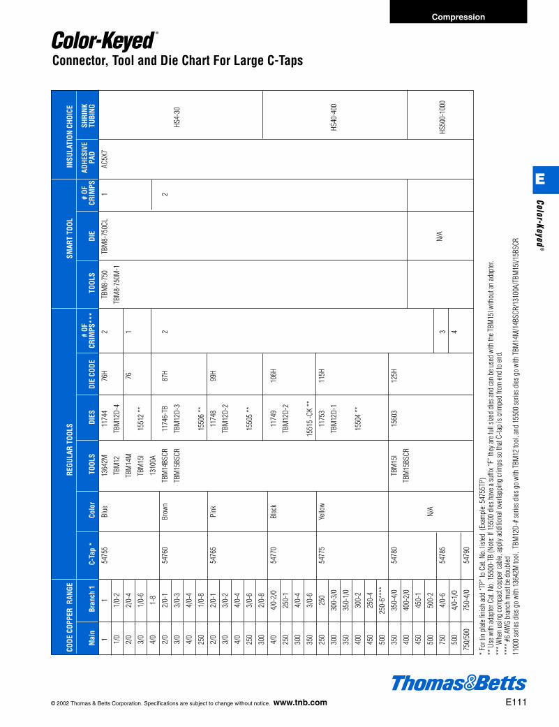
© 2002 Thomas & Betts Corporation. Specifications are subject to change without notice. www.tnb.com E111
Compression
E
Color-Keyed®
CODE
COP
PER
RAN
GERE
GULA
R TO
OLS
SMAR
T TO
OLIN
SULA
TION
CHO
ICE
# OF
#
OFAD
HESI
VE
SHRI
NK
Mai
nBr
anch
1C-
Tap
*Co
lor
TOOL
SDI
ESDI
E CO
DECR
IMPS
***
TOOL
SDI
ECR
IMPS
PAD
TUBI
NG
11
5475
5Bl
ue13
642M
1174
476
H2
TBM
8-75
0TB
M8-
750C
L1
AC5X
7
1/0
1/0-
2TB
M12
TBM
12D-
4TB
M8-
750M
-1
2/0
2/0-
4TB
M14
M76
1
3/0
1/0-
6TB
M15
I15
512
**
4/0
1-8
1310
0A
2/0
2/0-
154
760
Brow
nTB
M14
BSCR
1174
6-TB
87H
22
3/0
3/0-
3TB
M15
BSCR
TBM
12D-
3HS
4-30
4/0
4/0-
4
250
1/0-
815
506
**
2/0
2/0-
154
765
Pink
1174
899
H
3/0
3/0-
2TB
M12
D-2
4/0
4/0-
4
250
3/0-
615
505
**
300
2/0-
8
4/0
4/0-
2/0
5477
0Bl
ack
1174
910
6H
250
250-
1TB
M12
D-2
300
4/0-
4
350
3/0-
615
515
-CK
**
250
250
5477
5Ye
llow
1175
311
5H
300
300-
3/0
TBM
12D-
1HS
40-4
00
350
350-
1/0
400
300-
215
504
**
450
250-
4
500
250-
6***
*
350
350-
4/0
5478
0TB
M15
I15
603
125H
400
400-
2/0
TBM
15BS
CR
450
450-
1
500
500-
2N/
A
750
4/0-
654
785
3N/
AHS
500-
1000
500
4/0-
1/0
4
750/
500
750-
4/0
5479
0
* For
tin
plate
fini
sh ad
d “T
P” to
Cat.
No.
liste
d (E
xam
ple:
5475
5TP)
** U
se w
ith ad
apter
Cat.
No.
155
00-T
B (N
ote:
If 15
500
dies
hav
e a su
ffix “
F” th
ey ar
e ful
l size
d di
es an
d ca
n be
use
d wi
th th
e TBM
15I w
ithou
t an
adap
ter.
*** W
hen
usin
g co
mpa
ct co
pper
cabl
e, ap
ply a
dditi
onal
over
lappi
ng cr
imps
so th
at C-
tap is
crim
ped
from
end
to en
d.**
** #
6 AW
G br
anch
mus
t be d
oubl
ed11
000
serie
s dies
go
with
136
42M
tool
, TB
M12
D-#
serie
s dies
go
with
TBM
12 to
ol, a
nd 1
5500
serie
s dies
go
with
TBM
14M
/14B
SCR/
1310
0A/T
BM15
I/15B
SCR
Connector, Tool and Die Chart For Large C-Taps
412031.E01 CK 3/5 3/13/03 8:23 PM Page 111

E112 © 2002 Thomas & Betts Corporation. Specifications are subject to change without notice. www.tnb.com
Compression
Tool Services
90 DAYS
• Electronic Operated Tools(Printers, Testers)
• Individual Die
1 YEAR
• Pneumatic Tools• Cable Cutters, Strippers• TY-Tools• ID Systems
2 YEARS• Mechanical Hand Tools With
Ratchet or Shure-Stake®
• Hydraulic Pumps(Battery Operated ToolsIncluded)
5 YEARS• Mechanical Hand Tools Without
Ratchet or Shure-Stake®
• Hydraulic Tools(Self-Contained andRemote Heads)
LIFETIME
• Electricians' Supply Hand Tools
Thomas & Betts Tool ServiceThomas & Betts Tool Service has a
staff of highly trained, experiencedand dedicated technicians and appli-cation specialists to support our cus-tomers in every aspect of their toolingneeds.
The Tool Service Department iscapable of repairing all Thomas &Betts tools; from delicate fiber opticcleaving tools to large hydraulicpumps and crimping heads. Thedepartment is also responsible forwarranty repairs and will supply aloaner tool when necessary.
For the customer that is capable ofrepairing their own tools, Tool Servicealso sells the component parts. Inaddition, they can provide the techni-cal data and information required.
Other services include the calibra-tion or certification of tools to meet
applicable standards including“inhouse” certification of tools for larg-er OEM’S in conjunction with the ISO9000 programs. Tool Service alsoadministrates the lease tools availablefor the OEM market. There is also atool rental program powered towardcontractor jobs where the tools will beneeded for a relatively short period oftime.
The Application Tool Specialist alsosupports the field sales organization intool demos, customer training and toolinstallations. Arrangements are madewith the local sales representative.
There are four Thomas & Betts ToolService Centers to serve our cus-tomers quickly and efficiently, locatednear Philadelphia, PA., Chicago, IL,Reno, NV and Charlotte, NC. Contactthe service center most convenient for you.1-800-284-TOOL (8665)
Limited Warranty
Thomas & Betts manufactures these tools to be free of defects in material and workmanship for the time specified below. Shouldany defect occur during the specified time period, Thomas & Betts will repair or replace the tool at its option.
Limitations and Exclusions
THIS WARRANTY IS IN LIEU OF ALL OTHER REPRESENTATIONS AND EXPRESSED AND IMPLIED WARRANTIES(INCLUDING THE IMPLIED WARRANTIES OF MERCHANTABILITY AND FITNESS FOR USE) AND UNDER NOCIRCUMSTANCES SHALL THOMAS & BETTS BE LIABLE FOR ANY INCIDENTAL OR CONSEQUENTIALDAMAGES OR LOSSES.
THIS WARRANTY IS NON-TRANSFERABLE AND REPLACEMENT OF DEFECTIVE PARTS MUST BE MADE AT AFACILITY DESIGNATED BY THE MANUFACTURER.
Direct all inquiries to: Thomas & Betts Tool Repair Center1-800-284-TOOL (8665)
E
Colo
r-Ke
yed®
412031.E01 CK 3/5 3/13/03 8:23 PM Page 112

Product Overview . . . . . . . . . . . . . . . . . . . . . . . . . . F2
Compression H-Tap Connectors . . . . . . . . . . . F3-F11
Service Entrance Connectors . . . . . . . . . . . . F11-F15
Distribution Compression Connectors. . . . . . F16-F22
Compression Stirrup Connectors . . . . . . . . . F23-F25
Colour-Coded Compression Connectors. . . . . . . . . . . . . . . . . . . . . . . . . F26-F34
Automatic Splices . . . . . . . . . . . . . . . . . . . . . . . . . F35
Automatic Deadends. . . . . . . . . . . . . . . . . . . F36-F37
Service Wedge Clamps . . . . . . . . . . . . . . . . . . . . F38
Compression
F
412031.F01 BB 3/6 3/14/03 8:30 AM Page 1
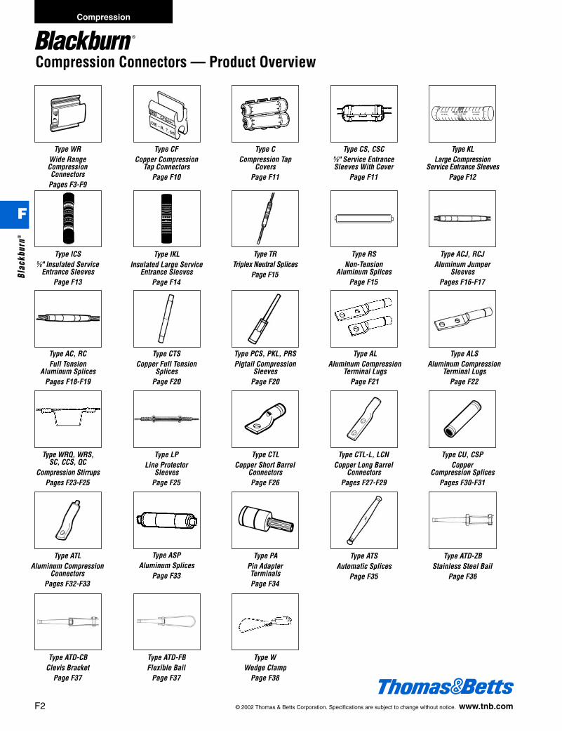
F2 © 2002 Thomas & Betts Corporation. Specifications are subject to change without notice. www.tnb.com
Compression Connectors — Product Overview
Compression
F
Blac
kbur
n®
Type WRWide RangeCompressionConnectors
Pages F3-F9
Type KLLarge Compression
Service Entrance SleevesPage F12
Type ICS5⁄8" Insulated Service
Entrance SleevesPage F13
Type TRTriplex Neutral Splices
Page F15
Type RSNon-Tension
Aluminum SplicesPage F15
Type ACJ, RCJAluminum Jumper
SleevesPages F16-F17
Type AC, RCFull Tension
Aluminum SplicesPages F18-F19
Type CTSCopper Full Tension
SplicesPage F20
Type PCS, PKL, PRSPigtail Compression
SleevesPage F20
Type ALAluminum Compression
Terminal LugsPage F21
Type LPLine Protector
SleevesPage F25
Type CFCopper Compression
Tap ConnectorsPage F10
Type CCompression Tap
CoversPage F11
Type CS, CSC5⁄8" Service EntranceSleeves With Cover
Page F11
Type IKLInsulated Large Service
Entrance SleevesPage F14
Type ALSAluminum Compression
Terminal LugsPage F22
Type WRQ, WRS,SC, CCS, QC
Compression StirrupsPages F23-F25
Type CTLCopper Short Barrel
ConnectorsPage F26
Type CTL-L, LCNCopper Long Barrel
ConnectorsPages F27-F29
Type CU, CSPCopper
Compression SplicesPages F30-F31
Type ATLAluminum Compression
ConnectorsPages F32-F33
Type ASPAluminum Splices
Page F33
Type PAPin AdapterTerminalsPage F34
Type ATSAutomatic Splices
Page F35
Type ATD-ZBStainless Steel Bail
Page F36
Type ATD-CBClevis Bracket
Page F37
Type ATD-FBFlexible Bail
Page F37
Type WWedge Clamp
Page F38
412031.F01 BB 3/6 3/14/03 8:30 AM Page 2

Compression H-Tap Connectors
Standard Conductor Compact Conductor Diameter (in.) No. Indents
Main Tap Main Tap Main TapACSR Str. Sol. ACSR Str. Sol. ACSR Str. ACSR Str. max. min. max. min.
• For combinations of aluminum-aluminumand aluminum-copper conductors.
• Pass the requirements of ANSI C119.4.• Standard compression tools and dies install
all sizes.• Seven Connector Program provides superior
connector performance, lower connectioncosts and simplified installation procedures.
• Fold-in tabs provide positive tab interlock astool closes.
• Field-proven ribbed design providesunpalled connector/conductor contact,without distorting the conductor’s shape.
• Made of 1350 aluminum alloy.• Pre-filled with an oxide inhibitor which is
held captive in the rib/connection area• RUS Listed.• All connectors reversible.• For copper to copper combinations,
use CF type shown on page F10.
Conductor Range InstallationInformation
WR159 1 .332 .162 .332 .162 17⁄16" O 4 2
WR289 3
WR379 5
WR419 7
WR399 6
WR279 4
WR189 2
.470 .398 .332 .162 113⁄16" D 5 2
.563 .475 .332 .162 113⁄16" D 5 2
.419 .266 .332 .162 111⁄16" O 5 2
.470 .336 .470 .336 113⁄16" D 5 2
.563 .461 .447 .338 2 3⁄16" D 6 2
.563 .461 .563 .461 2 7⁄16" D 7 3
Mech. Hyd.Tool Tool
Cat.No.
ConnectorNo.
Con-nectorLength
L
Con-nector
Die
Type WR – “O” and “D” Die Seven Connector Program
246
12346
246
246
246
12346
12346
12346
1246
1246
1/012
2/01/012
3/02/01/01
246
12346
1/01246
2/01/012
2/01/012
1246
12346
2/01/0
3/02/0
4/03/0
246
12346
1/01246
2/01/012
2/01/012
1246
12346
246
12346
1/01246
2/01/01
3/02/01/0
4/03/02/0
246
2346
3/02/0 3/0
4/03/0 4/0 —
1/01246
246
12346
26618⁄12504/0
2662504/0
1246
12346
4/03/0
4/03/0 —
2/01/01
2/01/0
3/02/0
26618⁄14/03/0
2662504/0
2/01/0
3/02/01/0
4/03/0
4/03/0 — 4/0
3/04/03/0 —
26618⁄14/03/0
2662504/0
26618⁄14/03/0
2662504/0
Type WR – Wide Range Aluminum Tap Connectors
© 2002 Thomas & Betts Corporation. Specifications are subject to change without notice. www.tnb.com F3
Compression
F
Blackburn®
412031.F01 BB 3/6 3/14/03 8:30 AM Page 3

Compression H-Tap Connectors
WR219
WR299
WR239
WR229
WR269
Standard Conductor Compact Conductor Diameter (in.) No. Indents
Main Tap Main Tap Main TapACSR Str. Sol. ACSR Str. Sol. ACSR Str. ACSR Str. max. min. max. min.
Conductor Range InstallationInformation
WR149 .266 .162 .266 .162 11⁄2" O 5 2
WR199
WR259
WR1010
WR179
.419 .232 .419 .232 13⁄4" O 4 2
.398 .324 .398 .316 17⁄8" D 5 2
.398 .266 .332 .232 13⁄4" O 5 2
.419 .326 .412 .292 17⁄8" D 5 2
.447 .365 .332 .236 17⁄8" D 5 2
.470 .410 .398 .316 17⁄8" D 5 2
Mech. Hyd.Tool ToolCat. No.
Con-nectorLength
L
Con-nector
Die
.398 .266 .266 .162 13⁄4" O 5 2
.470 .398 .266 .162 11⁄2" D 4 2
.447 .410 .447 .336 17⁄8" D 5 2
46
346
2346
46
46
346
2346
346
2346
2346
1/0123
1/012
1 46
346
2346
1/012
2/01/012
1234
12
1/0123
1/012
1234
1234
12
1/012
2/01/012
46
2346
2/01/01234
1/01234
12
1/01234
2/01/01234
12
2/01/01234
2/01/012
2/01/01234
2/01/012
1/01
2/01/0 — 1/0
12/01/0 — 2/0
1/02/01/0
2/01/0
2/01/0
1/01
2/01/0
3/02/0 — 3/0
2/046
346
2346
46
2346
3/0
1/01 —
1/012
1/01 — 1/0 2/0
1/0 1/0 2/01/0
2/01/0
2/01/0 —
234
123
12
2/01/0
1234
12
4/03/0
2/0
2/0 2/0
3/02/0 —
—
—
—
1/012
1/01
2/01/0
2/01/0
3/02/0 3/0
2/0 3/0
1/01
2/01/0
2/01/0
3/02/01/0
Tap
Main
Type WR – Supplemental “O” and “D” Die Connectors
F4 © 2002 Thomas & Betts Corporation. Specifications are subject to change without notice. www.tnb.com
Compression
F
Blac
kbur
n®
412031.F01 BB 3/6 3/14/03 8:30 AM Page 4
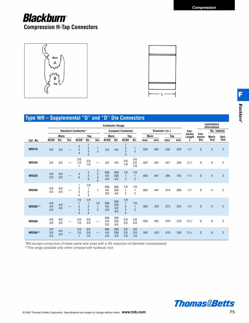
© 2002 Thomas & Betts Corporation. Specifications are subject to change without notice. www.tnb.com F5
Compression H-Tap Connectors
WR389**
WR389
Standard Conductor* Compact Conductor Diameter (in.) No. Indents
Main Tap Main Tap Main TapACSR Str. Sol. ACSR Str. Sol. ACSR Str. ACSR Str. max. min. max. min.
WR319 .502 .461 .332 .229 17⁄8" D 5 2
WR359
WR369**
WR369
WR339
.563 .461 .374 .266 17⁄8" D 4 2
.563 .423 .470 .336 2 3⁄16" D 6 2
.563 .461 .266 .162 17⁄8" D 4 2
.563 .423 .373 .232 17⁄8" D 5 2
Mech. Hyd.Tool ToolCat. No.
Con-nectorLength
L
Con-nector
Die
.502 .461 .447 .336 2 1⁄8" D 6 2
.563 .461 .470 .376 2 3⁄16" D 6 2
*Will accept conductors of these same wire sizes with a 3% reduction of diameter (compressed).**This range possible only when crimped with hydraulic tool.
4/03/02/0
3/0
3/0
4/03/0
4/03/0
4/03/0
4/03/02/0
4/03/0 — 4
6
346
2346
2664/03/0
2662504/0
1/012
1/012
3/0 —234
1234
12 3/0 4/0
1234
12
3/0 —2/01/01
2/01/0 — 3/0 4/0 2/0
1/0
3/02/01/0
4/03/0 —
1234
1/0123
12664/03/0
2662504/0
1/012
1/012
4/03/0 —
1/01234
2664/03/0
1/01234
1/012
2662504/03/0
1/01234
1/012
4/03/0 — 2/0
1/03/02/0 —
2664/03/0
2662504/0
3/02/0
3/02/0
4/03/0 —
2/01/01
3/02/01/0
—2664/03/0
2662504/0
3/02/01/0
3/02/01/0
Type WR – Supplemental “O” and “D” Die ConnectorsConductor Range Installation
Information
Tap
Main
Compression
F
Blackburn®
412031.F01 BB 3/6 3/14/03 8:30 AM Page 5
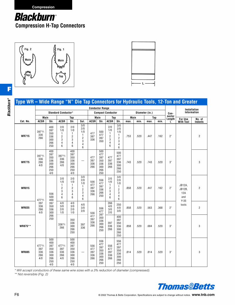
Compression H-Tap Connectors
* Will accept conductors of these same wire sizes with a 3% reduction of diameter (compressed).** Not reversible (Fig. 2)
WR885
Standard Conductor* Compact Conductor Diameter (in.)
Main Tap Main Tap Main TapACSR Str. ACSR Str. Sol. ACSR Str. ACSR Str. max. min. max. min.
WR715 .753 .520 .447 .162 2" 2
WR815
WR875**
WR835
WR775
.858 .520 .563 .368 2" 2
.858 .520 .447 .162 2" 2
.858 .520 .684 .520 3" 3
For Use No. ofWith Tool IndentsCat. No.
Con-nectorLength
L
.743 .520 .743 .520 3" 3
.814 .520 .814 .520 3" 3
Main
Tap
Main
Tap
400397350336300266250
4003973503363002662504/0
4003973503363002662504/0
500477397350336300266250
500477397336300266250
556500400397350336300266250
39718⁄1336266
39718⁄13362664/0
556477397336266250
2/01/012346
3/02/01/012346
477397336
2/01/012346
2/01/012346
3/02/01/012346
500477397350
39718⁄13362664/0
—477397336266
477397336266
3/02/01/012346
2/01/012346
3/02/01/012346
2/01/012346
2/01/012346
556477397336266
400397350336300266250
2664/03/02/0
47718⁄13973362664/0
556477397350336300266250
2504/03/0
556477397350336300266250
556477397336266
397336266
5004003973503363002662504/0
4/03/02/0
4/03/02/01/0
4/03/02/01/0
397336
350336300266250
33618⁄1266
556477397350336300266250
5004003973503363002662504/0
—
556477397336266
556477397336266
47718⁄13973362664/0
47718⁄13973362664/0
JB12A,JB12B,
12AandY-35tools
Fig. 1Fig. 2
Type WR – Wide Range “N” Die Tap Connectors for Hydraulic Tools, 12-Ton and GreaterConductor Range Installation
Information
F6 © 2002 Thomas & Betts Corporation. Specifications are subject to change without notice. www.tnb.com
Compression
F
Blac
kbur
n®
412031.F01 BB 3/6 3/14/03 8:30 AM Page 6
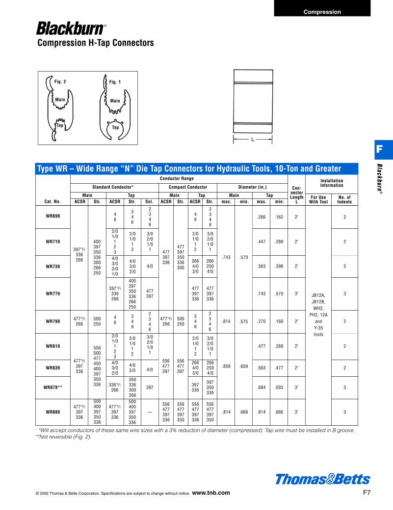
© 2002 Thomas & Betts Corporation. Specifications are subject to change without notice. www.tnb.com F7
Compression H-Tap Connectors
Main
Tap
Main
Tap
Fig. 1Fig. 2
WR819
Standard Conductor* Compact Conductor Diameter (in.)
Main Tap Main Tap Main TapACSR Str. ACSR Str. Sol. ACSR Str. ACSR Str. max. min. max. min.
Conductor Range InstallationInformation
WR699
WR739
WR719
.563 .477 2" 2
.684 .593 3" 3
For Use No. ofWith Tool IndentsCat. No.
Con-nectorLength
L
.814 .666 3" 3
477397336
2662504/0
46
2346
46
2346
39718⁄1336266
4/0
47718⁄1266
2664/03/0
46
477397
397350336
2/01/012
556477397350
3/02/01/01
397336
500400397350336
3/02/01/01
4/03/02/0
39733618⁄1266
556477397350
—
556477397336
556477397336
47718⁄1397336
47718⁄1397336
4/03/02/0
2/01/012
WR779
WR799
400397350336266250
346
2/01/012
WR839 4/03/0
WR879**
WR889
350336300266500400397350336
346
2/01/0123
4/03/02/01/0
2/01/0123
3/02/01/01
2346
4/0
500250
2/01/012
3/02/01/01
477397336
346
2346
2664/03/0
2662504/0
.477 .289 2" 2
.270 .160 2" 2
.743 .570 3" 3
.563 .398 2" 2
.447 .289 2" 2
.266 .162 2" 2
.814 .575
.666.814
500250
556500477450400397350336
47718⁄1266
47718⁄1397336
556477397
556477397
.858 .659
JB12A,JB12B,WH2,
PH2, 12AandY-35tools
.570.743
400397350336300266250
39718⁄1336266
477397336
477397350336300
*Will accept conductors of these same wire sizes with a 3% reduction of diameter (compressed). Tap wire must be installed in B groove.**Not reversible (Fig. 2).
Type WR – Wide Range “N” Die Tap Connectors for Hydraulic Tools, 10-Ton and Greater
Compression
F
Blackburn®
412031.F01 BB 3/6 3/14/03 8:30 AM Page 7

954900874
1000900
Compression H-Tap Connectors
Main
Tap
WR999
Standard Conductor Compact Conductor Diameter (in.)
Main Tap Main Tap Main TapACSR Str. ACSR Str. ACSR Str. ACSR Str. max. min. max. min.
Conductor RangeInstallationInformation
WR909 .684 .398 4 3⁄4 R 4
WR949
WR989
WR969
WR929
Cat. No.
Con-nectorLength
L
900874800795750715700636600
3503362662504/03/02/0
79526⁄7715666636605556
477 30⁄7
954874795
636556477397
1000954874795750
700636556477450
900874800795750715700636600
55618⁄1477397336300
1000954874795750
55618⁄1477397336300
JB60A,JB60B,
Y60,60Aand
PH-3tools
For Use Connector No. ofWith Tool Die Indents
600556550500400477450400397350336
3973503363002662504/03/0
3971⁄23362664/03/02/0
33618⁄12664/03/02/01/0
55618⁄1477397336300
636556477397
700636556500477450
600556550500477450400397350336
636556477397
700636556477450
3973503363002662504/03/0
.893 .666 4 3⁄4 R 4
.666.893
600556550500477450400397350336
39718⁄13362664/03/02/0
3503362662504/03/02/0
79526⁄7715666636605556
477 30⁄7
33618⁄12664/03/02/01/0
954874795
.8831.108
954 45⁄7900874795715666
10331000900800795750
954 45⁄7900874795715666
10331000900800795750
954900
1000900 1.172 .997
.684 .398 4 3⁄4 R 4
1.108 .883 4 3⁄4 R 4
.893 .666 4 3⁄4 R 4
1.172 .997 4 3⁄4 R 4
Type WR – Wide Range “R” Die Tap Connectors
F8 © 2002 Thomas & Betts Corporation. Specifications are subject to change without notice. www.tnb.com
Compression
F
Blac
kbur
n®
412031.F01 BB 3/6 3/14/03 8:30 AM Page 8

© 2002 Thomas & Betts Corporation. Specifications are subject to change without notice. www.tnb.com F9
Fig. 1 Fig. 2
Compression H-Tap Connectors
Standard Conductor* Diameter (in.) No. IndentsMain Tap A Tap B Main Tap A Tap B
ACSR Str. Sol. Str. Sol. Str. Sol. max. min. max. min. max. min.
Conductor Range Installation Information
WR9 .292 .184 .146 .064 — — 13⁄16" 3 —
WR502
WR502**
WR139
Mech. Hyd.Tool ToolCat. No.
Con-nectorLength
L
Con-nector
Die
* Will accept conductors of these same wire sizes with a 3% reduction of diameter (compressed).** This range possible only when crimped with hydraulic tool.
2
—
346
2346
1234
4/03/02/01/0
1/01234
4/03/0
FigureNo.
1
1
1
12
4/03/0
2/01/0123
4/03/02/01/0
—
810
8101214
810
810
8101214
68
10
68
10
68
10
— —
1214
1214
1214
1214
1214
1214
.419 .250 .162 .100 .092 .064 11⁄2" O 4 2
.563 .461 .162 .100 .092 .064 11⁄2" D 4 —
.563 .365 .162 .100 .092 .064 11⁄2" D — 2
5⁄8BG
Main
Tap A
Main
Tap ATap B
Type WR – Street Lighting Compression Connectors
Compression
F
Blackburn®
412031.F01 BB 3/6 3/14/03 8:30 AM Page 9
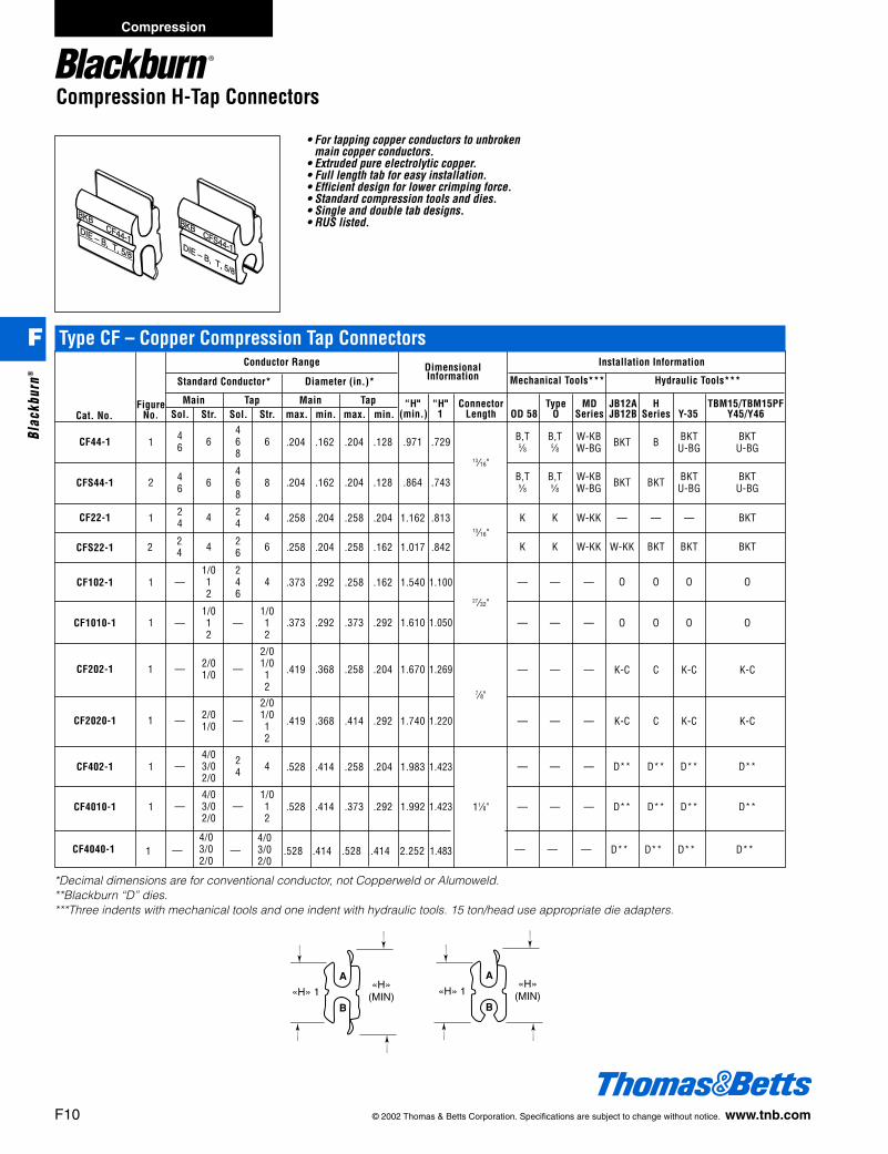
Compression H-Tap Connectors
BKBCFS44-1DIE – B, T, 5/8
BKBCF44-1
DIE – B, T, 5/8
• For tapping copper conductors to unbroken main copper conductors.
• Extruded pure electrolytic copper.• Full length tab for easy installation.• Efficient design for lower crimping force.• Standard compression tools and dies.• Single and double tab designs.• RUS listed.
CF44-1
Cat. No.
1
FigureNo.
Standard Conductor* Diameter (in.)* Mechanical Tools*** Hydraulic Tools***
Main Tap Main TapSol. Str. Sol. Str. max. min. max. min.
Conductor Range Installation Information
“H" “H" Connector Type MD JB12A H TBM15/TBM15PF(min.) 1 Length OD 58 O Series JB12B Series Y-35 Y45/Y46
46 6
468
6 .204 .162 .204 .128 .971 .729
CFS44-1 2 46 6
468
8 .204 .162 .204 .128 .864 .743
41 24
24 4 .258 .204 .258 .204 1.162 .813CF22-1
CFS22-1 42 24
26 6 .258 .204 .258 .162 1.017 .842
CF102-1 1 —1/012
246
4 .373 .292 .258 .162 1.540 1.100
CF1010-1 1 —1/012
—1/012
.373 .292 .373 .292 1.610 1.050
1CF202-1 — 2/01/0 —
2/01/012
.419 .368 .258 .204 1.670 1.269
1CF2020-1 — 2/01/0 —
2/01/012
.419 .368 .414 .292 1.740 1.220
CF402-1 1 —4/03/02/0
24 4 .528 .414 .258 .204 1.983 1.423
CF4010-1 1 —4/03/02/0
—1/012
.528 .414 .373 .292 1.992 1.423
CF4040-1 1 —4/03/02/0
—4/03/02/0
.528 .414 .528 .414 2.252 1.483
B,T B,T W-KB BKT B BKT BKT5⁄8 5⁄8 W-BG U-BG U-BG
13⁄16"B,T B,T W-KB BKT BKT BKT BKT
5⁄8 5⁄8 W-BG U-BG U-BG
K K W-KK — — — BKT
K K W-KK W-KK BKT BKT BKT
— — — O O O O
— — — O O O O
— — — K-C C K-C K-C
— — — K-C C K-C K-C
— — — D** D** D** D**
— — — D** D** D** D**
— — — D** D** D** D**
*Decimal dimensions are for conventional conductor, not Copperweld or Alumoweld. **Blackburn “D” dies.***Three indents with mechanical tools and one indent with hydraulic tools. 15 ton/head use appropriate die adapters.
13⁄16"
27⁄32"
7⁄8"
11⁄8"
DimensionalInformation
A
B
«H» 1«H»
(MIN)
A
B
«H» 1«H»
(MIN)
Type CF – Copper Compression Tap Connectors
F10 © 2002 Thomas & Betts Corporation. Specifications are subject to change without notice. www.tnb.com
Compression
F
Blac
kbur
n®
412031.F01 BB 3/6 3/14/03 8:30 AM Page 10

© 2002 Thomas & Betts Corporation. Specifications are subject to change without notice. www.tnb.com F11
CS61‡ CSC61 — 8 str. Green — 8 str. .162 .146 Green6 sol. 6 sol.
CS62‡ CSC62 6 6⁄1 6 str. Blue 1 10 str. .128 .116 Brown4 sol. 8 sol.
CS63‡ CSC63 6 6⁄1 6 str. Blue — 8 str. .162 .146 Green4 sol. 6 sol.
CS64‡ CSC64 6 6⁄1 6 str. Blue 6 6⁄1 6 str. .204 .184 Blue4 sol. 4 sol.
CS65‡ CSC65 46⁄1,7⁄1 3-4 str. Orange — 10 str. .128 .116 Brown
2 sol. 8 sol.
CS66‡ CSC66 46⁄1,7⁄1 3-4 str. Orange — 8 str. .162 .146 Green
2 sol. 6 sol.
CS67‡ CSC67 46⁄1,7⁄1 3-4 str. Orange 6 6⁄1 6 str. .204 .184 Blue
2 sol. 4 sol.
CS68‡ CSC68 46⁄1,7⁄1 3-4 str. Orange 46⁄1,
7⁄1 3-4 str. .258 .232 Orange2 sol. 2 sol.
CS69‡ CSC69 2 6⁄1,7⁄1 1-2 str. Red — 10 str. .128 .116 Brown
8 sol.
CS70‡ CSC70 2 6⁄1,7⁄1 1-2 str. Red — 8 str. .162 .146 Green
6 sol.
CS71‡ CSC71 2 6⁄1,7⁄1 1-2 str. Red 6 6⁄1 6 str. .204 .184 Blue
4 sol.
CS72‡ CSC72 2 6⁄1,7⁄1 1-2 str. Red 4 6⁄1,
7⁄1 3-4 str. .258 .232 Orange2 sol.
CS73‡ CSC73 2 6⁄1,7⁄1 1-2 str. Red 2 6⁄1,
7⁄1 1-2 str. .328 .292 Red
CS74‡ CSC74 1/0 1/0 str. Yellow — 8 str. .162 .146 Green6 sol.
CS75‡ CSC75 1/0 1/0 str. Yellow 6 6⁄1 6 str. .204 .184 Blue4 sol.
CS76‡ CSC76 1/0 1/0 str. Yellow 4 6⁄1,7⁄1 3-4 str. .258 .232 Orange
2 sol.
CS77‡ CSC77 1/0 1/0 str. Yellow 2 6⁄1,7⁄1 1-2 str. .328 .292 Red
CS78‡ CSC78 1/0 1/0 str. Yellow 1/0 1/0 str. .398 .368 Yellow
CS84‡ CSC84 — 2/0 str. Grey 1/0 1/0 str. .398 .368 Yellow
CS85‡ CSC85 — 2/0 str. Grey — 2/0 str. .414 .414 Grey
Types CS and CSC – Service Entrance Sleeves, e Die
.162 .146
.204 .184
.258 .232
.398 .368
.414 .414
.328 .292
BareSleeve ASCR AWG max. min. ASCR AWG max. min.
Conductor RangeDiameter (in.)
Conductor RangeDiameter (in.)Sleeve
WithCover
Cat. No.End “A" End “B”
ColourCode
ColourCode
‡ RUS Listed.
• Hinged polyethylene cover.• Installs easily, quickly–less expensive than
taping.• Positive snap-locks fasten securely.• Drain ports prevent accumulation of
corrosion-causing moisture.• Ultra-violet stabilized.
Compression H-Tap Connectors/Service Entrance Connectors
Type C – Compression Connector CoversDimension
Cat. No. Capacity* Height Length Width
C2BB All e" O.D., sleeves 2" long or less 1.10 4.00 1.05C5C All “O” Die taps, 1f" long or less 1.60 3.75 1.25C7C All “D” Die taps, 2d" long or less 1.80 5.00 1.45C9 All “N” and “D” die taps, up to 2" long 2.75 4.25 2.00C9L All “N” and “D” die taps, up to 5" long 2.75 7.25 2.00
*Before compression
• For combinations of aluminum-aluminumand aluminum-copper conductors.
• Pass the requirements of ANSI C119.4.• Sleeves are made of highly conductive
aluminum.• Quick identification with colour-coded foil
caps.• Install with standard compression dies.
Installation DiesCat. No. Mech. Hyd.
All 5⁄8 (OD58 Tool) Peach, U-BGBG, G, TU B58CS, 52
Installation Information
Compression
F
Blackburn®
412031.F01 BB 3/6 3/14/03 8:30 AM Page 11

Service Entrance Connectors
• For combinations of aluminum-aluminumand aluminum-copper conductors.
• Pass the requirements of ANSI C119.4.• Splices large conductors required for
commercial service; use as low costreducing sleeve.
• All sizes can be installed with popularmechanical and hydraulic tools.
• Center stop assures proper conductor positioning.
• Quick identification with colour-coded foilcaps.
KL20-1 6 str. .184 .167 Blue 6 str. .184 .167 Blue6 str. compact 6 str. compact
KL22-1 4 str. .232 .211 Orange 4 str. .232 .167 Orange4 str. compact 4 str. compact
2 str. 2 str.KL25-1 2 str. compact .292 .266 Red 2 str. compact .292 .266 Red
1/0 sol. Al, 1 str. 1/0 sol. Al, 1 str.KL31-1 2 ACSR, .336 .316 Red 1 str. compact .336 .316 Red
1/0 str. comp 2 ACSR
1/0 ACSR 1/0 ACSRKL36-1 1/0 str. .398 .368 Yellow 1/0 str. .398 .368 Yellow
2/0 str. compact 2/0 str. compact
KL45-1 2 ACSR, 1–2 str. .328 .292 Red1 str. compact
KL46-1 1/0 ACSR, 1/0 str. .398 .368 Yellow2/0 str. compact
KL47-1 2/0 ACSR, 2/0 str. .448 .414 Gray3/0 str. compact
KL54-1 4 ACSR, 3– 4 str. .258 .232 Orange2 sol.
KL55-1 2 ACSR, 1–2 str. .328 .268 Red1 str. compact
KL56-1 1/0 ACSR, 1/0 str. .398 .368 Yellow2/0 str. compact
KL57-1 2/0 ACSR, 2/0 str. .448 .414 Gray3/0 str. compact
KL58-1 3/0 ACSR, 3/0 str. .502 .464 Black4/0 str. compact
KL64-1 4 ACSR, 3– 4 str. .258 .232 Orange2 sol.
KL65-1 2 ACSR, 1–2 str. .328 .268 Red1 str. compact
KL66-1 1/0 ACSR, 1/0 str. .398 .368 Yellow2/0 str. compact
KL67-1 2/0 ACSR, 2/0 str. .448 .414 Gray3/0 str. compact
KL68-1 3/0 ACSR, 3/0 str. .502 .464 Black4/0 str. compact
KL69-1 4/0 ACSR, 4/0 str. .563 .522 Pink
max. min. max. min.
Conductor RangeDiameter (in.)
Conductor RangeDiameter (in.)
Cat. No.
End “A" End “B”
ColorCode
ColorCode
2/0 ASCR2/0 str. .448 .414 Gray
3/0 str. compact
3/0 ASCR3/0 str. .502 .464 Black
4/0 str. compact
4/0 ASCR4/0 str. .563 .522 PinkInstallation Dies
Cat. No. Mech. Hyd.
All 840, W-K840 840, U-K840EEI-11A, TX U-249, B49EA
Type KL – Large Compression Service EntranceSleeves, 840 Die
Installation Information
F12 © 2002 Thomas & Betts Corporation. Specifications are subject to change without notice. www.tnb.com
Compression
F
Blac
kbur
n®
412031.F01 BB 3/6 3/14/03 8:30 AM Page 12

© 2002 Thomas & Betts Corporation. Specifications are subject to change without notice. www.tnb.com F13
Service Entrance Connectors
ICS61-1 — 8 str. .162 .144 Green6 sol.
ICS62-1 — 10 str. .128 .114 Brown8 sol.
ICS63-1 — 8 str. .162 .144 Green6 sol.
ICS64-1 6 6 str. .204 .184 Blue4 sol.
ICS65-1 — 10 str. .128 .114 Brown8 sol.
ICS66-1 — 8 str. .162 .144 Green6 sol.
ICS67-1 6 6 str. .204 .184 Blue4 sol.
ICS68-1 4 3-4 str. .258 .213 Orange2 sol.
ICS70-1 — 8 str. .162 .144 Green6 sol.
ICS71-1 6 6 str. .204 .184 Blue4 sol.
ICS72-1 4 3-4 str. .258 .213 Orange2 sol.
ICS73-1 2 1-2 str. .328 .268 Red
ICS74-1 — 8 str. .162 .146 Green6 sol.
ICS75-1 6 6 st .204 .184 Blue4 sol.
ICS76-1 4 3-4 str. .258 .213 Orange2 sol.
ICS77-1 2 1-2 str. .328 .268 Red
ICS78-1 — 1/0 str. .398 .368 Yellow
• Pre-insulated for fast, easy installation withstandard tools.
• For combinations of aluminum andalu-minum-copper conductors.
• Pass the requirements of ANSI C119.4.
ASCR AWR max. min. ASCR AWR max. min.
Conductor RangeDiameter (in.)
Conductor RangeDiameter (in.)
Cat. No.
End “A" End “B”
ColourCode
ColourCode
6 6 str. .204 .184 Blue4 sol.
4 3-4 str. .258 .213 Orange2 sol.
2 1-2 str. .328 .268 Red
1/0 1/0 .398 .368 Yellow
All are RUS Listed.
— 8 str. .162 .144 Green6 sol.
Installation DiesCat. No. Mech. Hyd.
All 5⁄8 (OD58 Tool) Peach, U-BGBG, W-BG, G, TU B58CS
Installation Information
Type ICS – Service Entrance Sleeves, e Die
Compression
F
Blackburn®
412031.F01 BB 3/6 3/14/03 8:30 AM Page 13

Service Entrance Connectors
• For combinations of aluminum-aluminumand aluminum-copper conductors.
• Pass the requirements of ANSI C119.4.• Use as a low tension reducing sleeve for
insulated conductor.• Pre-insulated for fast, easy installation of
large home or commercial service entrances.• Concave polyethylene end caps seal out
dirt, but are easily pierced when insertingconductor.
IKL34 4 ACSR .258 .213 Orange3– 4 str., 2 sol.
IKL35 2 ACSR .328 .268 Red1– 2 str.
1/0 ACSRIKL36 1/0 str. .398 .365 Yellow
2/0 str. comp
IKL44 4 ACSR .258 .213 Orange3– 4 str., 2 sol.
IKL45 2 ACSR .328 .268 Red1–2 str.
1/0 ACSRIKL46 1/0 str. .398 .365 Yellow
2/0 str. comp
2/0 ACSRIKL47 2/0 str. .448 .414 Grey
3/0 str. comp
IKL54 4 ACSR .258 .213 Orange3– 4 str., 2 sol.
IKL55 2 ACSR .328 .268 Red1– 2 str.
1/0 ACSRIKL56 1/0 str. .398 .365 Yellow
2/0 str. comp
2/0 ACSRIKL57 2/0 str. .448 .414 Grey
3/0 str. comp
3/0 ACSRIKL58 3/0 str. .502 .464 Black
4/0 str. comp
IKL64 4 ACSR .258 .213 Orange3– 4 str., 2 sol.
IKL65 2 ACSR .328 .268 Red1– 2 str.
IKL66 1/0 ACSR .398 .365 Yellow1/0 str.
2/0 ACSRIKL67 2/0 str. .448 .414 Grey
3/0 str. comp
3/0 ACSRIKL68 3/0 str. .502 .464 Black
4/0 str. comp
IKL69 4/0 ACSR .564 .522 Pink4/0 str.
max. min. max. min.
Conductor RangeDiameter (in.)
Conductor RangeDiameter (in.)
Cat. No.
End “A" End “B”
ColourCode
ColourCode
1/0 ASCR2/0 str. .398 .365 Yellow1/0 str.
(compact)
2/0 ASCR2/0 str. .448 .414 Grey3/0 str.
(compact)
3/0 ASCR3/0 str. .502 .464 Black4/0 str.
(compact)
4/0 ACSR .564 .522 Pink4/0 str.
Installation DiesCat. No. Mech. Hyd.
AllBY37, 840 B49EA, 840
W-K840, TX U-K840, U-249
All are RUS Listed.
Installation Information
Type IKL – Insulated Service Entrance Sleeves, 840 Die
F14 © 2002 Thomas & Betts Corporation. Specifications are subject to change without notice. www.tnb.com
Compression
F
Blac
kbur
n®
412031.F01 BB 3/6 3/14/03 8:30 AM Page 14

© 2002 Thomas & Betts Corporation. Specifications are subject to change without notice. www.tnb.com F15
Service Entrance Connectors
• Non tension splice frequently used forservice entrance on commercial-industrialloads.
• For end-to-end splicing of aluminum tocopper conductor, #4/0 str. through 1000MCM.
• Prefilled with oxide inhibitor.• Passes the requirements of ANSI C119.4.
Conductor RangeConductor Diameter* Cap
Cat. No. ACSR AWG max. min. Colour Length
TR61 6 6 str. .204 .184 Blue 41⁄4"4 sol.
TR63 4 4 str. .258 .232 Orange 41⁄4"2 sol.
TR64 2 2 str. .316 .292 Red 41⁄4"
TR65 1 1/0 str. .373 .355 Yellow 6"
TR66 1/0 — .398 .373 Yellow 6"
Cat. No. Installation Dies
All 5⁄8, Peach, G, TU
*Decimal dimensions are for conventional conductor, not Copperweld or Alumoweld.
max.-min. max.-min. max.-min. max.-min.
Conductor RangeDiameter (in.)
Conductor RangeDiameter (in.)
Cat. No.
End “A" End “B” InstallationDies
HydraulicToolLength
RS253 300-250 MCM .630-.574 4/0 .528
RS2525 300-250 MCM .630-.574 300-250 MCM .630-.574
RS403 400-336 MCM .726-.666 4/0 .528
RS4025 400-336 MCM .726-.666 300-250 MCM .630-.574
RS4040 400-336 MCM .726-.666 400-336 MCM .726-.666
RS4525 500-450 MCM .813-.770 300-250 MCM .630-.574
RS4540 500-450 MCM .813-.770 400-336 MCM .726-.666
RS4545 500-450 MCM .813-.770 500-450 MCM .813-.770
RS8080 800-750 MCM 1.029-.997 800-750 MCM 1.029-.997
RS100100 1000-900 MCM 1.152-1.092 1000-900 MCM 1.152-1.092
6"
71⁄2"
8"
B20AH31815⁄16
6030AH352
Type TR – Triplex Neutral Splice, Semi-Tension, e Die
Installation Information
Type RS – Aluminum Compression Splice
Compression
F
Blackburn®
412031.F01 BB 3/6 3/14/03 8:30 AM Page 15

Distribution Compression Connectors
• Meets the 40% partial tension requirementof ANSI C119.4.
Type ACJ – Aluminum Jumper Sleeves for All Aluminum ConductorMechanical Tools Hydraulic Tools
OD58* MD Series O-52 JB12B Y Series WH Series
Crimps Crimps Crimps Dies Crimps Crimps Crimps EEIConductor per Die per per Cat. per Die per Die per Classi-
Cat. No. (Stranding) Lgth. Dies End Index End Dies End Nos. End Index End Index End fication
ACJ20 2/0(7, 19) 43⁄4" BY33 8 C-167 8 737 8 B39EA 2 247 2 737 4 10AW-247 4 747 4
ACJ205 2/0(7, 19) 43⁄4" BY41 4 W-245 4 635 4 B30EA 2 245 25⁄8–1 4 9A635 2
ACJ30 3/0(7, 19) 43⁄4" BY35 8 W-247 4 781 8 B74AH 2 247 2 781 4 —ACJ40 4/0(7, 19) 43⁄4" BY37 8 W-249 4 840 8 B49EA 2 249 2 840 4 11AACJ266 266.8(7, 19) 53⁄8" — — — — — — B75AH 3 251 3 11⁄2 3 —ACJ336 336.4(19, 37) 53⁄8" — — — — — — B80EA 3 321 3 11⁄8–1 3 13A
ACJ350 350(19) 6 3⁄4" — — — — — — B80EA 5 490 5 11⁄8–1 5 13A547
ACJ397 397.5(19) 6 3⁄4" — — — — — — B80EA 4 468 4 11⁄8–1 4 13A
ACJ477 477, 500 91⁄2" — — — — — — B80EA 6 317 6 11⁄8–1 6 13A(19, 37) 426
ACJ556 556.5(19, 37) 9 9⁄16" — — — — — — B76AH 8 318 9 11⁄8–1 11 —
*OD58 dies are interchangeable with those listed for 0-52.
F16 © 2002 Thomas & Betts Corporation. Specifications are subject to change without notice. www.tnb.com
Compression
F
Blac
kbur
n®
412031.F01 BB 3/6 3/14/03 8:30 AM Page 16
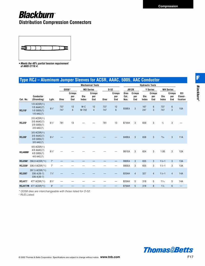
© 2002 Thomas & Betts Corporation. Specifications are subject to change without notice. www.tnb.com F17
Compression
F
Blackburn®
Distribution Compression Connectors
• Meets the 40% partial tension requirementof ANSI C119.4.
Type RCJ – Aluminum Jumper Sleeves for ACSR, AAAC, 5005, AAC ConductorMechanical Tools Hydraulic Tools
OD58* MD Series O-52 JB12B Y Series WH Series
Crimps Crimps Crimps Dies Crimps Crimps Crimps EEIConductor per Die per per Cat. per Die per Die per Classi-
Cat. No. (Stranding) Lgth. Dies End Index End Dies End Nos. End Index End Index End fication
1/0 ACSR(6⁄1)737 12 W-C 12 737 12 167 6 737 61/0 AAAC(7) 61⁄2" 747 6 W-702 4 747 6 B39EA 3 247 3 747 3 10A
RCJ10‡ 1/0 5005(7)1/0 AAC(7)
2/0 ACSR(6⁄1)
RCJ20‡ 2/0 AAAC(7) 6 3⁄4" 781 13 — — 781 13 B74AH 3 659 3 3⁄4 3 —2/0 5005(7)2/0 AAC(7)
3/0 ACSR(6⁄1)
RCJ30‡ 3/0 AAAC(7) 61⁄4" — — — — — — B49EA 3 658 3 29⁄32 3 11A3/0 5005(7)3/0 AAC(7)
4/0 ACSR(6⁄1)4/0 AAAC(7) 6 3⁄4" — — — — — — B61EA 3 654 3 1.00 3 12ARCJ40BB‡
4/0 5005(7)4/0 AAC(7)
RCJ266‡ 266.8 ACSR(18⁄1) 7" — — — — — — B80EA 3 655 3 11⁄8–1 3 13A
RCJ336‡ 336.4 ACSR(18⁄1) 7" — — — — — — B80EA 3 655 3 11⁄8–1 3 13A
397.5 ACSR(18⁄1)RCJ397 336.4(26-7) 71⁄4" — — — — — — B20AH 4 327 4 11⁄8–1 4 14A
336.4(30-7)
RCJ477 477 ACSR(18⁄1) 8 3⁄4" — — — — — — B20AH 5 318 5 15⁄16 5 14A
RCJ477M 477 ACSR(26⁄7) 9" — — — — — — B76AH 5 318 8 11⁄8 6 —
* OD58 dies are interchangeable with those listed for O-52.‡ RUS Listed.
412031.F01 BB 3/6 3/14/03 8:30 AM Page 17
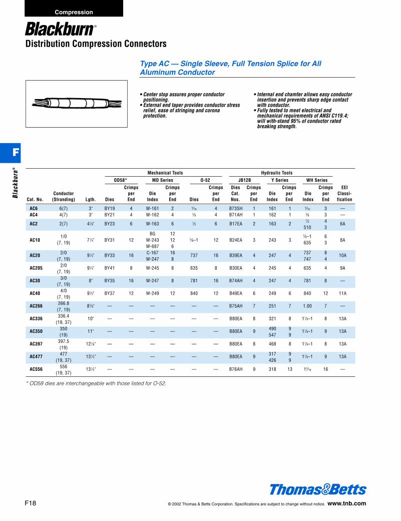
Distribution Compression Connectors
• Center stop assures proper conductorpositioning.
• External end taper provides conductor stressrelief, ease of stringing and coronaprotection.
• Internal end chamfer allows easy conductorinsertion and prevents sharp edge contactwith conductor.
• Fully tested to meet electrical andmechanical requirements of ANSI C119.4;will with-stand 95% of conductor ratedbreaking strength.
Mechanical Tools Hydraulic Tools
OD58* MD Series O-52 JB12B Y Series WH Series
Crimps Crimps Crimps Dies Crimps Crimps Crimps EEIConductor per Die per per Cat. per Die per Die per Classi-
Cat. No. (Stranding) Lgth. Dies End Index End Dies End Nos. End Index End Index End fication
AC6 6(7) 3" BY19 4 W-161 2 5⁄16 4 B73SH 1 161 1 5⁄16 3 —AC4 4(7) 3" BY21 4 W-162 4 3⁄8 4 B71AH 1 162 1 3⁄8 3 —
AC2 2(7) 41⁄8" BY23 6 W-163 6 1⁄2 6 B17EA 2 163 21⁄2 4 6A
510 3
1/0 BG 12 5⁄8–1 6AC10 (7, 19) 71⁄4" BY31 12 W-243 12 5⁄8–1 12 B24EA 3 243 3 635 3 8A
W-687 6
AC20 2/0 91⁄4" BY33 16 C-167 16 737 16 B39EA 4 247 4 737 8 10A(7, 19) W-247 8 747 4
AC205 2/0 91⁄4" BY41 8 W-245 8 635 8 B30EA 4 245 4 635 4 9A(7, 19)
AC30 3/0 8" BY35 16 W-247 8 781 16 B74AH 4 247 4 781 8 —(7, 19)
AC40 4/0 91⁄2" BY37 12 W-249 12 840 12 B49EA 6 249 6 840 12 11A(7, 19)
AC266 266.8 85⁄8" — — — — — — B75AH 7 251 7 1.00 7 —(7, 19)
AC336 336.4 10" — — — — — — B80EA 8 321 8 11⁄8–1 8 13A(19, 37)
AC350 350 11" — — — — — — B80EA 9 490 9 11⁄8–1 9 13A(19) 547 9
AC397 397.5 121⁄8" — — — — — — B80EA 8 468 8 11⁄8–1 8 13A(19)
AC477 477 131⁄2" — — — — — — B80EA 9 317 9 11⁄8–1 9 13A(19, 37) 426 9
AC556 556 131⁄2" — — — — — — B76AH 9 318 13 15⁄16 16 —(19, 37)
* OD58 dies are interchangeable with those listed for O-52.
Type AC — Single Sleeve, Full Tension Splice for AllAluminum Conductor
F18 © 2002 Thomas & Betts Corporation. Specifications are subject to change without notice. www.tnb.com
Compression
F
Blac
kbur
n®
412031.F01 BB 3/6 3/14/03 8:30 AM Page 18

© 2002 Thomas & Betts Corporation. Specifications are subject to change without notice. www.tnb.com F19
Distribution Compression Connectors
• Center stop assures proper conductorpositioning.
• Replaces two-piece splices.• External end taper provides conductor stress
relief, ease of stringing and corona protection.
• Internal end chamfer allows easy conductorinsertion and prevents sharp edge contactwith conductor.
• Tested to meet electrical and mechanicalrequirements of ANSI C119.4; will withstand95% of conductor rated breaking strength.
Mechanical Tools Hydraulic Tools
OD58* MD Series O-52 JB12B Y Series WH Series
Crimps Crimps Crimps Dies Crimps Crimps Crimps EEIConductor per Die per per Cat. per Die per Die per Classi-
Cat. No. (Stranding) Lgth. Dies End Index End Dies End Nos. End Index End Index End fication
4ACSR(6⁄1,7⁄1)4AAAC(7) 12" 1⁄2 24 W-163 24 1⁄2 24 B72AH 6 163 6
1⁄2 12 —RC4BB‡
4 5005(7) 510 64AAC(7)
4ACSR(6⁄1,7⁄1) BG 24RC45‡ 4AAAC(7) 12"
5⁄8–1 24 W-BG 245⁄8–1 24 B24EA 6 243 6 5⁄8–1 12 8A
4 5005(7) 635 12 W-243 12 635 12 687 6 635 64AAC(7)
2ACSR(6⁄1,7⁄1)2AAAC(7) 13 5⁄8"
5⁄8–1 28 BG 28 5⁄8–1 28 B24EA 7 245 7 5⁄8–1 14 9ARC2BB‡
2 5005(7) 635 14 W-245 14 635 14 B30EA 687 7 635 72AAC(7)
2ACSR(6⁄1,7⁄1) W-C 28 167 14RC25‡ 2AAAC(7) 13 5⁄8" 737 28 W-247 28 737 28 B39EA 7 247 14 737 14 10A
2 5005(7) 747 14 W-702 14 747 14 702 7 747 72AAC(7)
1/0 ACSR(6⁄1) 167 8RC10‡ 1/0 AAAC(7) 151⁄4" 737 32 W-C 32 737 32 B39EA 8 247 8 737 16 10A
1/0 5005(7) 747 16 W-702 16 747 16 702 81/0 AAC(7)
RC205‡ 2/0 ACSR (6⁄1) 17" 737 36 W-702 18 737 36 B39EA 9 247 9 — — 10A747 18 747 18
2/0 ACSR(6⁄1)
RC20‡ 2/0 AAAC(7) 16" 781 32 — — 781 32 B74AH Overlap 659 Overlap 3⁄4 Overlap —2/0 5005(7)2/0 AAC(7)
3/0 ACSR(6⁄1)
RC30‡ 3/0 AAAC(7) 17" — — — — — — B49EA Overlap 658 Overlap 29⁄32 Overlap 11A3/0 5005(7)3/0 AAC(7)
4/0 ACSR(6⁄1)
RC40‡ 4/0 AAAC(7) 181⁄2" — — — — — — B61EA Overlap 654 Overlap 1.00 12A4/0 5005(7) 1–2 Overlap
4/0 AAC(7)
RC336 336.4 ACSR(18⁄1) 191⁄4" — — — — — — B80EA Overlap 655 Overlap 11⁄8–1 Overlap 13A11⁄8–2
RC397 397.5 ACSR(18⁄1) 211⁄2" — — — — — — B20AH Overlap 327 Overlap 11⁄8–1 Overlap 14A11⁄8–2
RC477 477 ACSR(18⁄1) 24" — — — — — — B78AH Overlap 788 Overlap 15⁄16 Overlap —
‡ RUS Listed* OD58 dies are interchangeable with those listed for O-52.
Type RC — Single Sleeve, Full Tension Splice, for ACSR,AAAC, 5005, AAC Conductor
Compression
F
Blackburn®
412031.F01 BB 3/6 3/14/03 8:30 AM Page 19
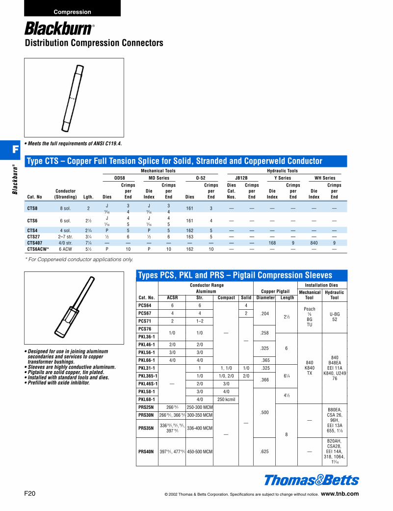
Distribution Compression Connectors
• Meets the full requirements of ANSI C119.4.
Type CTS – Copper Full Tension Splice for Solid, Stranded and Copperweld ConductorMechanical Tools Hydraulic Tools
OD58 MD Series O-52 JB12B Y Series WH Series
Crimps Crimps Crimps Dies Crimps Crimps CrimpsConductor per Die per per Cat. per Die per Die per
Cat. No (Stranding) Lgth. Dies End Index End Dies End Nos. End Index End Index End
CTS8 8 sol. 2 J 3 J 3 161 3 — — — — — —5⁄16 4 5⁄16 4
CTS6 6 sol. 21⁄2 J 4 J 4 161 4 — — — — — —5⁄16 5 5⁄16 5
CTS4 4 sol. 2 3⁄4 P 5 P 5 162 5 — — — — — —CTS27 2–7 str. 31⁄4 1⁄2 6 1⁄2 6 163 5 — — — — — —CTS407 4/0 str. 71⁄4 — — — — — — — — 168 9 840 9CTS6ACW* 6 ACW 51⁄2 P 10 P 10 162 10 — — — — — —
* For Copperweld conductor applications only.
• Designed for use in joining aluminumsecondaries and services to copper transformer bushings.
• Sleeves are highly conductive aluminum.• Pigtails are solid copper, tin plated.• Installed with standard tools and dies.• Prefilled with oxide inhibitor.
Conductor Range Installation DiesAluminum Copper Pigtail Mechanical Hydraulic
Cat. No. ACSR Str. Compact Solid Diameter Length Tool Tool
PCS64 6 6 4
PCS67 4 4 2
PCS71 2 1–2
PCS76
PKL36-1
PKL46-1 2/0 2/0
PKL56-1 3/0 3/0
PKL66-1 4/0 4/0 .365
PKL31-1 1 1, 1/0 1/0 .325
PKL365-1 1/0 1/0, 2/0 2/0
PKL46S-1 2/0 3/0
PKL58-1 3/0 4/0
PKL68-1 4/0 250 kcmil
PRS25N 266 26⁄7 250-300 MCM
PRS30N 266 26⁄7, 366 18⁄1 300-350 MCM
336 30⁄7,26⁄7,18⁄1,PRS35N 397 18⁄1 336-400 MCM
PRS40N 39718⁄1, 47718⁄1 450-500 MCM
—
—
—
—
1/0 1/0
—
.204
.258
.325
.366
.500
.625
21⁄2
6
61⁄4
41⁄2
8
Peach5⁄8BGTU
U-BG52
840K840
TX
—
—
840B48EA
EEI 11AK840, U249
76
B80EA,CSA 26,
96H,EEI 13A655, 11⁄8
B20AH,CSA28,EEI 14A,
318, 1064,15⁄16
Types PCS, PKL and PRS – Pigtail Compression Sleeves
F20 © 2002 Thomas & Betts Corporation. Specifications are subject to change without notice. www.tnb.com
Compression
F
Blac
kbur
n®
412031.F01 BB 3/6 3/14/03 8:30 AM Page 20
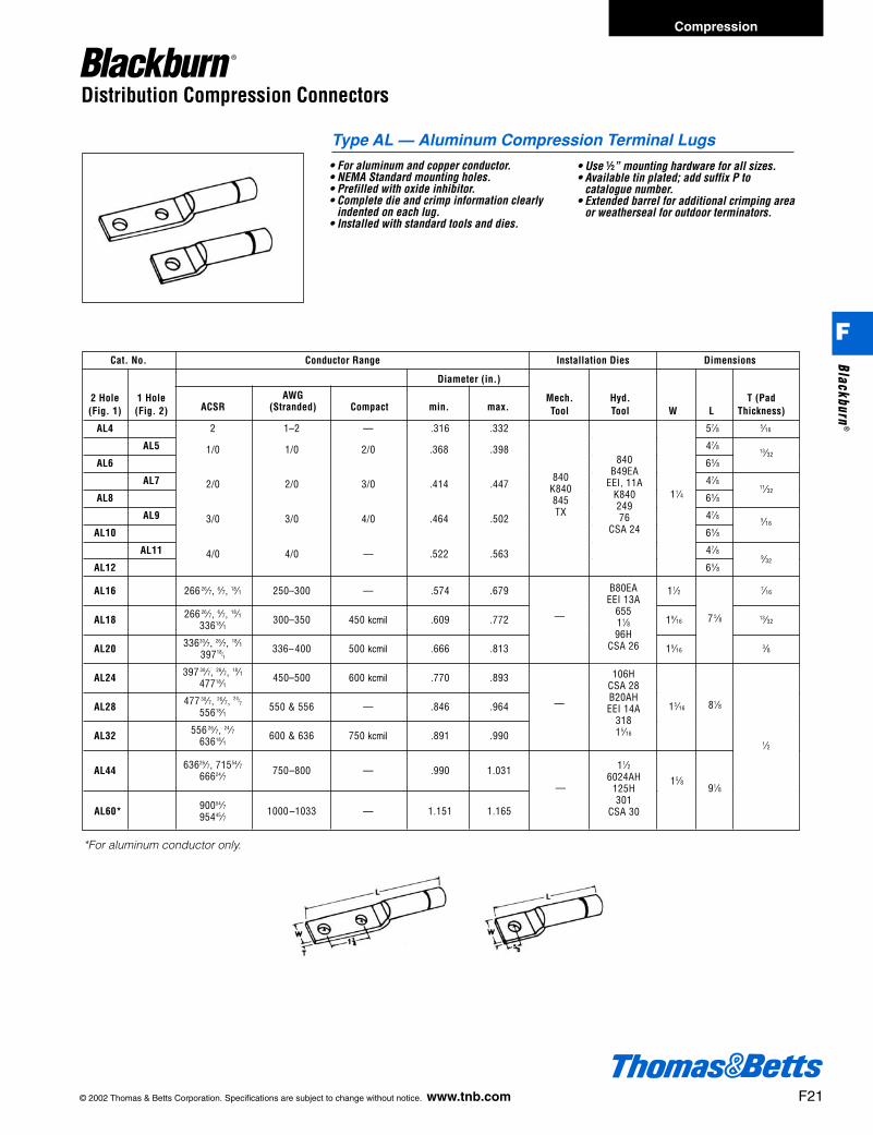
© 2002 Thomas & Betts Corporation. Specifications are subject to change without notice. www.tnb.com F21
Distribution Compression Connectors
• For aluminum and copper conductor.• NEMA Standard mounting holes.• Prefilled with oxide inhibitor.• Complete die and crimp information clearly
indented on each lug.• Installed with standard tools and dies.
• Use d” mounting hardware for all sizes.• Available tin plated; add suffix P to
catalogue number.• Extended barrel for additional crimping area
or weatherseal for outdoor terminators.
Cat. No. Conductor Range Installation Dies Dimensions
Diameter (in.)
2 Hole 1 Hole Mech. Hyd. T (Pad(Fig. 1) (Fig. 2) Tool Tool W L Thickness)
AL4 2 1–2 — .316 .332 57⁄8 5⁄16
AL5 47⁄8
AL6 65⁄8
AL7 47⁄8
AL8 65⁄8
AL9 47⁄8
AL10 65⁄8
AL11 47⁄8
AL12 65⁄8
AL16 266 26⁄7, 6⁄7, 18⁄1 250–300 — .574 .679 11⁄2 7⁄16
AL18 266 26⁄7, 6⁄7, 18⁄1 300–350 450 kcmil .609 .772 19⁄1613⁄3233618⁄1
AL20 33630⁄7, 26⁄7, 18⁄1 336– 400 500 kcmil .666 .813 19⁄163⁄839718⁄1
AL24 397 30⁄7, 26⁄7, 18⁄1 450–500 600 kcmil .770 .89347718⁄1
AL28 477 30⁄7, 26⁄7, 24⁄7 550 & 556 — .846 .96455618⁄1
AL32 556 26⁄7, 24⁄7 600 & 636 750 kcmil .891 .99063618⁄1
AL44 63626⁄7, 71554⁄7 750–800 — .990 1.03166624⁄7
AL60* 90054⁄7 1000 –1033 — 1.151 1.16595445⁄7
AWGACSR (Stranded) Compact min. max.
1/0 1/0 2/0 .368 .398
2/0 2/0 3/0 .414 .447
3/0 3/0 4/0 .464 .502
4/0 4/0 — .522 .563
840K840845TX
840B49EA
EEI, 11AK84024976
CSA 24
—
B80EAEEI 13A
65511⁄896H
CSA 26
106HCSA 28B20AHEEI 14A
31815⁄16
11⁄26024AH
125H301
CSA 30
—
—
11⁄4
15⁄16
15⁄8
7 5⁄8
81⁄8
91⁄8
13⁄32
11⁄32
5⁄16
9⁄32
1⁄2
Type AL — Aluminum Compression Terminal Lugs
*For aluminum conductor only.
Compression
F
Blackburn®
412031.F01 BB 3/6 3/14/03 8:30 AM Page 21
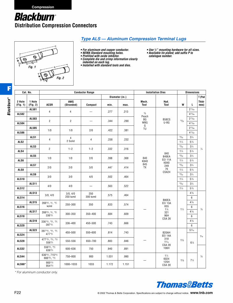
Distribution Compression Connectors
Cat. No. Conductor Range Installation Dies Dimensions
Diameter (in.) T (Pad
2 Hole 1 Hole Mech. Hyd. Thick-(Fig. 1) (Fig. 2) Tool Tool W L ness)
AL581 2 37⁄64
AL582 4 37⁄64
AL583 2 37⁄64
AL584 4 37⁄64
AL585 2 37⁄64
AL586 4 37⁄64
ALS1 29⁄32 31⁄4
ALS2 11⁄4 5 3⁄4
ALS3 29⁄32 31⁄4
ALS4 11⁄4 5 3⁄4
ALS5 29⁄32 31⁄4
ALS6 11⁄4 5 3⁄4
ALS7 29⁄32 31⁄4
ALS8 11⁄4 5 3⁄4
ALS9 29⁄32 31⁄4
ALS10 11⁄4 5 3⁄4
ALS11 29⁄32 31⁄4
ALS12 11⁄4 5 3⁄4
ALS13 4 5⁄8
ALS14 6
ALS15 4 5⁄8
ALS16 6
ALS17 4 5⁄8
ALS18 6
ALS19 4 5⁄8
ALS20 6
ALS23 5 9⁄16
ALS24
ALS28 477 30⁄7, 26⁄7, 24⁄7 550–556 650–700 .883 .84655618⁄1
ALS32 55626⁄7, 26⁄7 600–636 750 .940 .89163618⁄1
ALS44 63626⁄7, 71554⁄7 750–800 900 1.031 .99066626⁄7, 54⁄7
ALS60* 900 54⁄7 1000–1033 1033 1.172 1.151954 45⁄7
AWGACSR (Stranded) Compact min. max.
4 4 — .277 .213
2 2 — .344 .290
1/0 1/0 2/0 .422 .381
4 4 4 .258 .2322 Solid
5⁄8Peach
BGWBG
GTU
B58CSU-BG
840K840845TX
840B49EA
EEI 11AK84024976
CSA24
B80EAEEI 13A
65511⁄832196H
CSA 26
11⁄26024125H
CSA 30
—
—
29⁄32
11⁄4
67⁄8
15⁄8
13⁄8
71⁄4
1⁄4
9⁄16
5⁄8
3⁄8
• For aluminum and copper conductor.• NEMA Standard mounting holes.• Prefilled with oxide inhibitor.• Complete die and crimp information clearly
indented on each lug.• Installed with standard tools and dies.
• Use 1/2” mounting hardware for all sizes.• Available tin plated; add suffix P to
catalogue number.
* For aluminum conductor only.
2 1–2 1–2 .332 .316
1/0 1/0 2/0 .398 .368
2/0 2/0 3/0 .447 .414
3/0 3/0 4/0 .502 .464
4/0 4/0 — .563 .522
3/0, 4/0 3/0, 4/0 250 .575 .464250 kcmil 300 kcmil
26626⁄7, 6⁄7, 18⁄1 250–300 350 .633 .574kcmil
26626⁄7, 6⁄7, 18⁄1 300–350 350–400 .684 .60933618⁄1
336 30⁄7, 26⁄7, 18⁄1 336–400 450–500 .743 .66639718⁄1
397 30⁄7, 26⁄7, 18⁄1 450–500 550–600 .814 .74347718⁄1
—
B20AHEEI 14A
31815⁄16
CSA 28106H
Fig. 1
Fig. 2
Type ALS — Aluminum Compression Terminal Lugs
F22 © 2002 Thomas & Betts Corporation. Specifications are subject to change without notice. www.tnb.com
Compression
F
Blac
kbur
n®
412031.F01 BB 3/6 3/14/03 8:30 AM Page 22
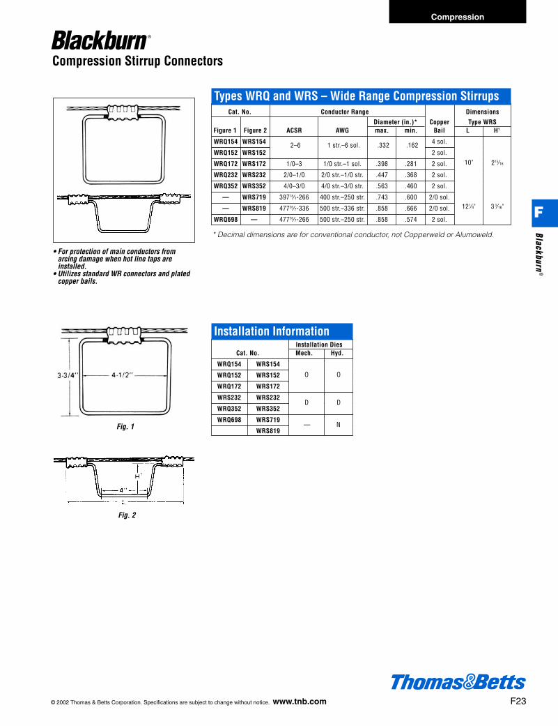
© 2002 Thomas & Betts Corporation. Specifications are subject to change without notice. www.tnb.com F23
Compression Stirrup Connectors
• For protection of main conductors fromarcing damage when hot line taps areinstalled.
• Utilizes standard WR connectors and platedcopper bails.
Fig. 2
Fig. 1
Cat. No. Conductor Range Dimensions
Diameter (in.)* Copper Type WRSFigure 1 Figure 2 ACSR AWG max. min. Bail L H1
WRQ154 WRS154 4 sol.
WRQ152 WRS152 2 sol.
WRQ172 WRS172 1/0–3 1/0 str.–1 sol. .398 .281 2 sol.
WRQ232 WRS232 2/0–1/0 2/0 str.–1/0 str. .447 .368 2 sol.
WRQ352 WRS352 4/0–3/0 4/0 str.–3/0 str. .563 .460 2 sol.
— WRS719 39718⁄1-266 400 str.–250 str. .743 .600 2/0 sol.
— WRS819 47726⁄7-336 500 str.–336 str. .858 .666 2/0 sol.
WRQ698 — 47726⁄7-266 500 str.–250 str. .858 .574 2 sol.
2–6 1 str.–6 sol. .332 .162
10" 215⁄16
121⁄4" 3 3⁄16"
Installation DiesCat. No. Mech. Hyd.
WRQ154 WRS154
WRQ152 WRS152
WRQ172 WRS172
WRS232 WRS232
WRQ352 WRS352
WRQ698 WRS719
WRS819
O O
D D
— N
* Decimal dimensions are for conventional conductor, not Copperweld or Alumoweld.
Types WRQ and WRS – Wide Range Compression Stirrups
Installation Information
Compression
F
Blackburn®
412031.F01 BB 3/6 3/14/03 8:30 AM Page 23

Compression Stirrup Connectors
• Aluminum connector elements are designedto be pre-loaded for faster installation intopopular “hot stick” tools and compressedusing standard “O,” “D” and “N” dies.
• Connectors are prefilled with inhibitorcompound.
• Wide range–only 4 sizes cover #6 solid to500 kcmil stranded.
Fig. 2Fig. 1
Cat. No. Bail Wire SizeDimensions (in)
W H
7019 #2 solid copper 10" 215⁄16"7020 2/0 solid copper 121⁄4" 3 3⁄16"7030 #2 solid copper 41⁄2" 3 3⁄4"7030C #2 solid copper 41⁄2" 3 3⁄4"
• Tin plated for lower contact resistance.• Knurled to resist rotation.
Types SC and QC – Wide Range Compression StirrupsConductor Range Bail
Cat. No. Diameter (Tin Plated) Installation Dies Dimensions (in.)Fig. 1 Fig. 2 ACSR AWG Alum. (in.) mm Size Diameter (mm) Mech. Hyd. L H
QCO 02 SCO 02 2-6 2 str.–6 sol. .325-.162 8.25-.412 #2 solid 6.35 O O 8 3⁄4 31⁄8QCO 21 SCO 21 2/0-2 2/0 str.–2 str. .414-.292 10.51-7.41 #2 solid 6.35 O O 8 3⁄4 31⁄8QCD 41 SCD 41 4/0-3/0 4/0 str.–3/0 str. .563-.464 14.29-10.51 #2 solid 6.35 D — 8 3⁄4 31⁄8QCN 50 SCN 50 47718⁄1-4/0 500–4/0 str. .814-.528 20.66-13.40 1/0 solid 6.22 — N 11 311⁄16
7019
70207030
7030C
Plated Copper Bail
F24 © 2002 Thomas & Betts Corporation. Specifications are subject to change without notice. www.tnb.com
Compression
F
Blac
kbur
n®
412031.F01 BB 3/6 3/14/03 8:30 AM Page 24
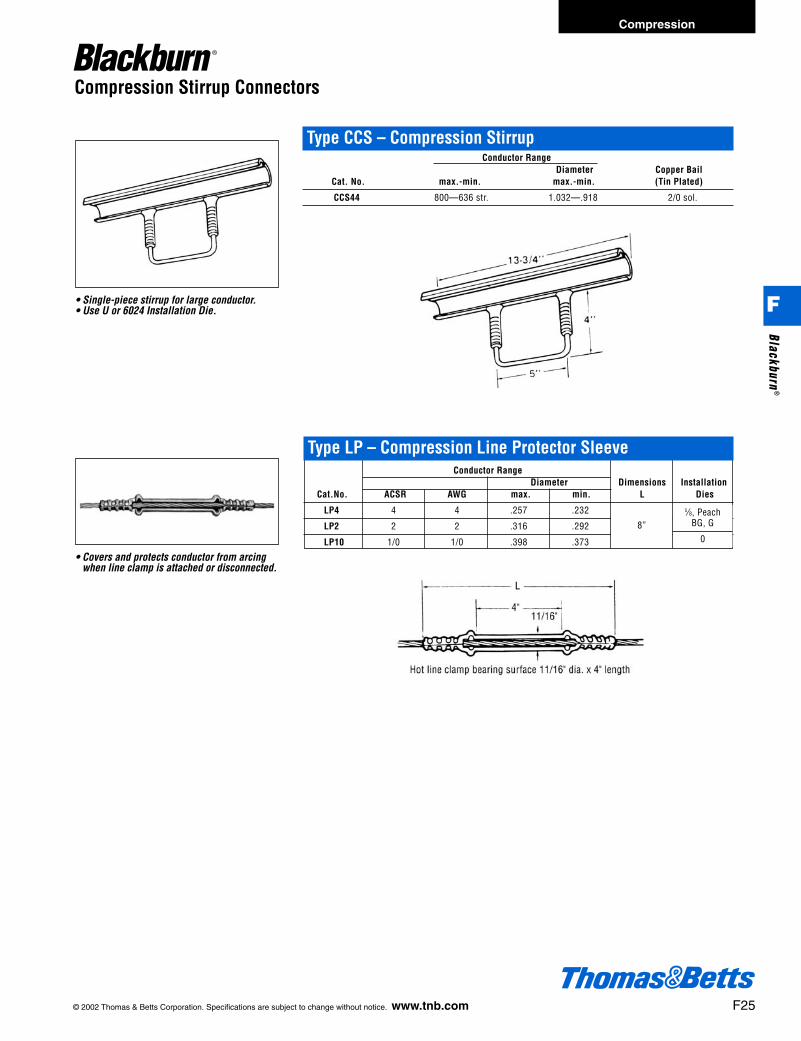
© 2002 Thomas & Betts Corporation. Specifications are subject to change without notice. www.tnb.com F25
Compression Stirrup Connectors
• Covers and protects conductor from arcingwhen line clamp is attached or disconnected.
Conductor RangeDiameter Dimensions Installation
Cat.No. ACSR AWG max. min. L Dies
LP4 4 4 .257 .232
LP2 2 2 .316 .292
LP10 1/0 1/0 .398 .373
• Single-piece stirrup for large conductor.• Use U or 6024 Installation Die.
Type CCS – Compression StirrupConductor Range
Diameter Copper BailCat. No. max.-min. max.-min. (Tin Plated)
CCS44 800—636 str. 1.032—.918 2/0 sol.
8”
5⁄8, PeachBG, G
0
Type LP – Compression Line Protector Sleeve
Compression
F
Blackburn®
412031.F01 BB 3/6 3/14/03 8:30 AM Page 25
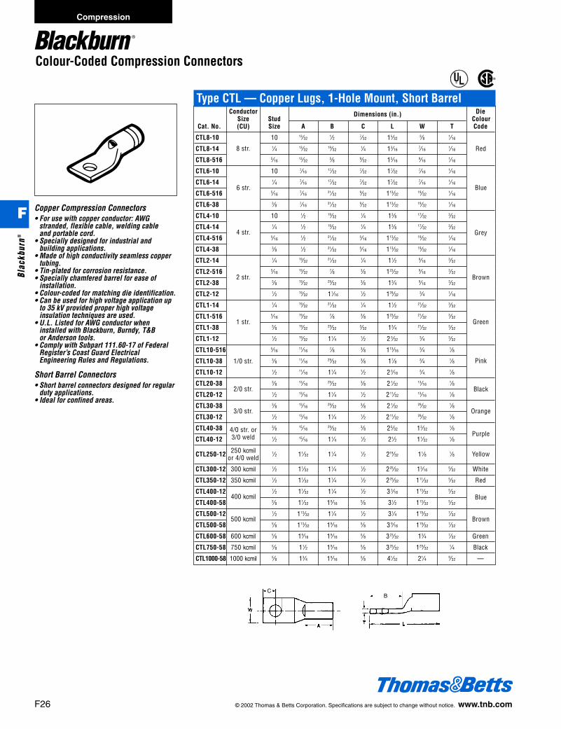
F26 © 2002 Thomas & Betts Corporation. Specifications are subject to change without notice. www.tnb.com
Compression
F
Blac
kbur
n®
Copper Compression Connectors• For use with copper conductor: AWG
stranded, flexible cable, welding cableand portable cord.
• Specially designed for industrial andbuilding applications.
• Made of high conductivity seamless coppertubing.
• Tin-plated for corrosion resistance.• Specially chamfered barrel for ease of
installation.• Colour-coded for matching die identification.• Can be used for high voltage application up
to 35 kV provided proper high voltageinsulation techniques are used.
• U.L. Listed for AWG conductor wheninstalled with Blackburn, Burndy, T&Bor Anderson tools.
• Comply with Subpart 111.60-17 of FederalRegister’s Coast Guard ElectricalEngineering Rules and Regulations.
Short Barrel Connectors• Short barrel connectors designed for regular
duty applications.• Ideal for confined areas.
Conductor Dimensions (in.) DieSize Stud Colour
Cat. No. (CU) Size A B C L W T Code
CTL8-10 10 13⁄321⁄2 7⁄32 15⁄32
3⁄8 1⁄16
CTL8-14 1⁄4 13⁄3219⁄32
1⁄4 13⁄167⁄16
1⁄16
CTL8-516 5⁄1613⁄32
5⁄8 9⁄32 15⁄169⁄16
1⁄16
CTL6-10 10 7⁄1617⁄32
7⁄32 17⁄327⁄16
1⁄16
CTL6-14 1⁄4 7⁄1617⁄32
7⁄32 17⁄327⁄16
1⁄16
CTL6-516 5⁄167⁄16
21⁄329⁄32 113⁄32
19⁄321⁄16
CTL6-38 3⁄8 7⁄1621⁄32
9⁄32 113⁄3219⁄32
1⁄16
CTL4-10 10 1⁄2 19⁄321⁄4 13⁄8 17⁄32
3⁄32
CTL4-14 1⁄4 1⁄2 19⁄321⁄4 13⁄8 17⁄32
3⁄32
CTL4-516 5⁄161⁄2 21⁄32
5⁄16 113⁄3219⁄32
1⁄16
CTL4-38 3⁄8 1⁄2 21⁄325⁄16 113⁄32
19⁄321⁄16
CTL2-14 1⁄4 19⁄3221⁄32
1⁄4 11⁄2 9⁄163⁄32
CTL2-516 5⁄1619⁄32
7⁄8 3⁄8 123⁄329⁄16
3⁄32
CTL2-38 3⁄8 19⁄3229⁄32
3⁄8 13⁄4 9⁄163⁄32
CTL2-12 1⁄2 19⁄32 11⁄161⁄2 129⁄32
3⁄4 1⁄16
CTL1-14 1⁄4 19⁄3221⁄32
1⁄4 11⁄2 21⁄323⁄32
CTL1-516 5⁄1619⁄32
7⁄8 3⁄8 123⁄3221⁄32
3⁄32
CTL1-38 3⁄8 19⁄3229⁄32
3⁄32 13⁄4 21⁄323⁄32
CTL1-12 1⁄2 19⁄32 11⁄4 1⁄2 2 3⁄323⁄4 3⁄32
CTL10-516 5⁄1611⁄16
7⁄8 3⁄8 113⁄163⁄4 1⁄8
CTL10-38 3⁄8 11⁄1629⁄32
3⁄8 17⁄8 3⁄4 1⁄8
CTL10-12 1⁄2 11⁄16 11⁄4 1⁄2 2 3⁄163⁄4 1⁄8
CTL20-38 3⁄8 13⁄1629⁄32
3⁄8 2 1⁄3213⁄16
1⁄8
CTL20-12 1⁄2 13⁄16 11⁄4 1⁄2 211⁄3213⁄16
1⁄8
CTL30-38 3⁄8 13⁄1629⁄32
3⁄8 2 1⁄3229⁄32
1⁄8
CTL30-12 1⁄2 13⁄16 11⁄4 1⁄2 211⁄3229⁄32
1⁄8
CTL40-38 3⁄8 15⁄1629⁄32
3⁄8 25⁄32 13⁄321⁄8
CTL40-12 1⁄2 15⁄16 11⁄4 1⁄2 21⁄2 11⁄321⁄8
CTL250-12 250 kcmil 1⁄2 11⁄32 11⁄4 1⁄2 219⁄32 11⁄8 1⁄8or 4/0 weld
CTL300-12 300 kcmil 1⁄2 11⁄32 11⁄4 1⁄2 225⁄32 13⁄165⁄32 White
CTL350-12 350 kcmil 1⁄2 11⁄32 11⁄4 1⁄2 225⁄32 111⁄325⁄32 Red
CTL400-12 1⁄2 11⁄32 11⁄4 1⁄2 3 3⁄16 113⁄325⁄32
CTL400-58 5⁄8 11⁄32 19⁄165⁄8 31⁄2 113⁄32
5⁄32
CTL500-12 1⁄2 113⁄32 11⁄4 1⁄2 31⁄4 119⁄327⁄32
CTL500-58 5⁄8 113⁄32 19⁄165⁄8 3 9⁄16 119⁄32
7⁄32
CTL600-58 600 kcmil 5⁄8 19⁄16 19⁄165⁄8 323⁄32 13⁄4 7⁄32 Green
CTL750-58 750 kcmil 5⁄8 11⁄2 19⁄165⁄8 325⁄32 129⁄32
1⁄4 Black
CTL1000-58 1000 kcmil 5⁄8 13⁄4 19⁄165⁄8 41⁄32 21⁄4 9⁄32 —
8 str.
6 str.
4 str.
2 str.
1 str.
1/0 str.
2/0 str.
3/0 str.
4/0 str. or3/0 weld
400 kcmil
500 kcmil Brown
Blue
Yellow
Purple
Orange
Black
Pink
Green
Brown
Grey
Blue
Red
BC
®
®
Colour-Coded Compression Connectors
Type CTL — Copper Lugs, 1-Hole Mount, Short Barrel
412031.F01 BB 3/6 3/14/03 8:30 AM Page 26

© 2002 Thomas & Betts Corporation. Specifications are subject to change without notice. www.tnb.com F27
Compression
F
Blackburn®
Copper Compression Connectors• For use with copper conductor: AWG
stranded, flexible cable, welding cable anportable cord.
• Specially designed for industrial andbuilding applications.
• Made of high conductivity seamless coppertubing.
• Tin-plated for corrosion resistance.• Specially chamfered barrel for ease of
installation.• Colour-coded for matching die identification.• Can be used for high voltage application up
to 35 kV provided proper high voltage insula-tion techniques are used.
• U.L. Listed for AWG conductor wheninstalled with Blackburn, Burndy, T&B orAnderson tools.
• Comply with Subpart 111.60-17 of FederalRegister’s Coast Guard ElectricalEngineering Rules and Regulations.
Short Barrel Connectors• Short barrel connectors designed for regular
duty applications.• Ideal for confined areas.
®
®
Conductor Dimensions (in.) DieSize Stud Colour
Cat. No. (CU) Size A B C D L W T Code
CTL6-214 6 str. 1⁄2 11⁄4 1⁄4 5⁄8 131⁄3213⁄32
1⁄16 Blue
CTL4-214 4 str. 1⁄2 11⁄4 1⁄4 5⁄8 21⁄321⁄2 3⁄32 Grey
CTL2-2516 2 str. 19⁄32 15⁄8 3⁄8 3⁄4 215⁄329⁄16
3⁄32 Brown
CTL1-2516 1 str. 19⁄32 13⁄4 3⁄8 7⁄8 219⁄3221⁄32
3⁄32 Green
CTL10-2516 1/0 str. 11⁄16 13⁄4 3⁄8 7⁄8 211⁄163⁄4 1⁄8 Pink
CTL202 2/0 str. 13⁄16 213⁄161⁄2 13⁄4 313⁄16
13⁄161⁄8 Black
CTL302 3/0 str. 25⁄32 213⁄161⁄2 13⁄4 315⁄16
15⁄161⁄8 Orange
CTL402 4/0 str. 15⁄16 3 1⁄2 13⁄4 41⁄4 13⁄321⁄8 Purple
CTL2502 250 kcmil 11⁄32 3 1⁄2 13⁄4 411⁄32 11⁄8 5⁄32 Yellow
CTL3002 300 kcmil 11⁄32 3 1⁄2 13⁄4 417⁄32 13⁄165⁄32 White
CTL3502 350 kcmil 11⁄32 3 1⁄2 13⁄4 417⁄32 111⁄325⁄32 Red
CTL4002 400 kcmil 111⁄32 3 1⁄2 13⁄4 415⁄16 113⁄325⁄32 Blue
CTL5002 500 kcmil 13⁄8 3 1⁄2 13⁄4 5 117⁄327⁄32 Brown
CTL6002-38 3⁄8 117⁄32 129⁄323⁄8 13⁄4 51⁄8 123⁄32
7⁄32
CTL6002-12 117⁄32 3 1⁄2 13⁄4 51⁄8 123⁄327⁄32
CTL7502 750 kcmil 11⁄2 3 1⁄2 13⁄4 57⁄32 129⁄321⁄4 Black
CTL10002 1000 kcmil 13⁄4 3 1⁄2 13⁄4 57⁄16 21⁄4 9⁄32 —
600 kcmil Green
1⁄4
5⁄16
1⁄2
1⁄2
C D
A
W
B
LT
Colour-Coded Compression Connectors
Type CTL — Copper Lugs, 2-Hole Mount, Short Barrel
412031.F01 BB 3/6 3/14/03 8:30 AM Page 27

AB
C
W
LT
Conductor Flexible Dimensions (in.) DieSize AWG Conductor Stud Colour
Cat. No. (CU) Size Stranding Size A B C L W T Code
CTL8L-14 8 str. 8 37/24 25⁄325⁄8 1⁄4 15⁄8 13⁄32
1⁄16 Red
CTL6L-14 6 str. 6 61/24 25⁄325⁄8 1⁄4 15⁄8 13⁄32
1⁄16 Blue
CTL4L-14 4 str. 5 91/24 25⁄325⁄8 1⁄4 111⁄16
1⁄2 3⁄32 Grey
CTL2L-516 2 str. 3 125/24 7⁄8 7⁄8 3⁄8 2 1⁄329⁄16
3⁄32 Brown
CTL1L-516 1 str. 2 150/24 13⁄327⁄8 3⁄8 2 5⁄32
21⁄323⁄32 Green
CTL10L-516 1/0 str. 1 225/24 13⁄327⁄8 3⁄8 2 7⁄32
3⁄4 1⁄8 Pink
CTL20L-38 2/0 str. 1/0 275/24 3⁄8 13⁄3229⁄32
3⁄8 21⁄4 13⁄161⁄8 Black
CTL30L-12 3/0 str. 2/0 325/24 11⁄8 11⁄4 1⁄2 211⁄1629⁄32
1⁄8 Orange
CTL40L-12 4/0 str. — — 13⁄8 11⁄4 1⁄2 215⁄16 11⁄321⁄8 Purple
CTL250L-12 250 kcmil 3/0 450/24 119⁄32 11⁄4 1⁄2 31⁄8 11⁄8 1⁄8 Yellow
CTL300L-12 300 kcmil 4/0 550/24 125⁄32 11⁄4 1⁄2 317⁄32 13⁄161⁄8 White
CTL350L-12 350 kcmil 263 650/24 127⁄32 11⁄4 1⁄2 319⁄32 111⁄325⁄32 Red
CTL400L-58 400 kcmil 313 775/24 127⁄32 19⁄165⁄8 41⁄32 113⁄32
5⁄32 Blue
CTL500L-58 500 kcmil 373 925/24 211⁄32 19⁄165⁄8 41⁄2 119⁄32
3⁄16 Brown
CTL600L-58 600 kcmil 444 1100/24 21⁄8 19⁄165⁄8 4 5⁄16 123⁄32
7⁄32 Green
CTL750L-58 750 kcmil 535 1325/24 2 3⁄8 19⁄165⁄8 421⁄32 129⁄32
1⁄4 Black
CTL1000L-58 1000 kcmil 646 1600/24 27⁄8 19⁄165⁄8 55⁄32 21⁄4 9⁄32 —777 1925/24
1⁄4
5⁄16
1⁄2
5⁄8
F28 © 2002 Thomas & Betts Corporation. Specifications are subject to change without notice. www.tnb.com
Type CTL — Copper Lugs, 1-Hole Mount, Long Barrel
Copper Compression Connectors• For use with copper conductor: AWG
stranded, flexible cable, welding cableand portable cord.
• Specially designed for industrial andbuilding applications.
• Made of high conductivity seamless coppertubing.
• Tin-plated for corrosion resistance.• Specially chamfered barrel for ease of
installation.• Colour-coded for matching die identification.• Can be used for high voltage application up
to 35 kV provided proper high voltageinsulation techniques are used.
• U.L. Listed for AWG conductor wheninstalled with Blackburn, Burndy, T&Bor Anderson tools.
• Comply with Subpart 111.60-17 of FederalRegister’s Coast Guard ElectricalEngineering Rules and Regulations.
Long Barrel Connectors• Ideal for industrial, oil rig, mining, welding
and transportation electrical terminationapplications.
• Heavy duty design which permits additionalcrimp for added mechanical strength.
®
®
Colour-Coded Compression Connectors
Compression
F
Blac
kbur
n®
412031.F01 BB 3/6 3/14/03 8:30 AM Page 28
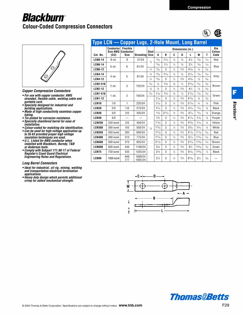
Conductor Flexible Dimensions (in.) DieSize AWG Conductor Stud Colour
Cat. No. (CU) Size Stranding Size A B C D L W T Code
LCN8-14 8 str. 8 37/24 25⁄32 13⁄161⁄4 5⁄8 21⁄8 15⁄32
1⁄16 Red
LCN6-14 25⁄32 11⁄4 1⁄4 5⁄8 21⁄4 13⁄321⁄16
LCN6-12 1⁄2 25⁄32 3 1⁄2 13⁄4 4 5⁄327⁄8 3⁄32
LCN4-14 1⁄4 25⁄32 13⁄161⁄4 5⁄8 2 3⁄16
17⁄323⁄16
LCN4-12 1⁄2 25⁄32 3 1⁄2 13⁄4 4 5⁄327⁄8 3⁄32
LCN2-516 5⁄167⁄8 15⁄8 3⁄8 3⁄4 215⁄16
9⁄163⁄32
LCN2-12 1⁄2 7⁄8 3 1⁄2 13⁄4 41⁄4 7⁄8 3⁄32
LCN1-516 5⁄16 11⁄32 15⁄8 3⁄8 7⁄8 2 31⁄3221⁄32
3⁄32
LCN1-12 11⁄32 3 1⁄2 13⁄4 413⁄327⁄8 3⁄32
LCN10 1/0 1 225/24 11⁄32 3 1⁄2 13⁄4 3 31⁄323⁄4 1⁄8 Pink
LCN20 2/0 1/0 275/24 15⁄16 3 1⁄2 13⁄4 4 3⁄1613⁄16
1⁄8 Black
LCN30 3/0 2/0 325/24 11⁄8 215⁄161⁄2 13⁄4 47⁄16
15⁄161⁄8 Orange
LCN40 4/0 — — 13⁄8 3 1⁄2 13⁄4 411⁄16 11⁄321⁄8 Purple
LCN250 250 kcmil 3/0 450/24 119⁄32 3 1⁄2 13⁄4 429⁄32 11⁄161⁄8 Yellow
LCN300 300 kcmil 4/0 550/24 125⁄32 3 1⁄2 13⁄4 59⁄32 13⁄161⁄8 White
LCN350 350 kcmil 263 650/24 127⁄32 3 1⁄2 13⁄4 511⁄32 111⁄325⁄32 Red
LCN400 400 kcmil 313 775/24 127⁄32 3 1⁄2 13⁄4 57⁄16 113⁄325⁄32 Blue
LCN500 500 kcmil 373 925/24 211⁄32 3 1⁄2 13⁄4 515⁄16 119⁄323⁄16 Brown
LCN600 600 kcmil 444 1100/24 21⁄8 3 1⁄2 13⁄4 53⁄4 123⁄327⁄32 Green
LCN75 750 kcmil 535 1325/24 2 3⁄8 3 1⁄2 13⁄4 6 3⁄32 129⁄321⁄4 Black
LCN99 1000 kcmil 646 1600/24 27⁄8 3 1⁄2 13⁄4 619⁄32 21⁄4 9⁄32 —777 1925/24
1⁄4
1⁄2
6 str. 6 61/24
4 str. 5 91/24
2 str. 3 125/24
1 str. 2 150/24
Blue
Grey
Brown
Green
AB
C
W
LT
D
© 2002 Thomas & Betts Corporation. Specifications are subject to change without notice. www.tnb.com F29
Type LCN — Copper Lugs, 2-Hole Mount, Long Barrel
Copper Compression Connectors• For use with copper conductor: AWG
stranded, flexible cable, welding cable andportable cord.
• Specially designed for industrial andbuilding applications.
• Made of high conductivity seamless coppertubing.
• Tin-plated for corrosion resistance.• Specially chamfered barrel for ease of
installation.• Colour-coded for matching die identification.• Can be used for high voltage application up
to 35 kV provided proper high voltage insulation techniques are used.
• U.L. Listed for AWG conductor wheninstalled with Blackburn, Burndy, T&Bor Anderson tools.
• Comply with Subpart 111.60-17 of FederalRegister’s Coast Guard ElectricalEngineering Rules and Regulations.
Long Barrel Connectors• Ideal for industrial, oil rig, mining, welding
and transportation electrical terminationapplications.
• Heavy duty design which permits additionalcrimp for added mechanical strength.
®
®
Colour-Coded Compression Connectors
Compression
F
Blackburn®
412031.F01 BB 3/6 3/14/03 8:30 AM Page 29

Conductor Length DieSize AWG Flexible Conductor L Colour
Cat. No. (CU) CMA Stranding (in.) Code
CU8 8 str. 8 37/24 Red
CU6 6 str. 6 61/24 Blue
CU4 4 str. 5 91/24 Grey
CU2 2 str. 3 125/24 17⁄8 Brown
CU1 1 str. 2 150/24 2 Green
CU10 1/0 str. 1 225/24 2 Pink
CU20 2/0 str. 1/0 275/24 21⁄8 Black
CU30 3/0 str. 2/0 325/24 21⁄4 Orange
CU40 4/0 str. — — 2 3⁄4 Purple
CU250 250 kcmil 3/0 450/24 3 3⁄8 Yellow
CU300 300 kcmil 4/0 550/24 31⁄2 White
CU350 350 kcmil 263 650/24 Red
CU400 400 kcmil 313 755/24 3 3⁄4 Blue
CU500 500 kcmil 373 925/24 4 3⁄4 Brown
CU600 600 kcmil 444 1100/24 41⁄4 Green
CU750 750 kcmil 535 1325/24 4 3⁄4 Black
CU1000 1000 kcmil 646 1600/24 55⁄8 —777 1925/24
L
13⁄4
2
3 3⁄4
F30 © 2002 Thomas & Betts Corporation. Specifications are subject to change without notice. www.tnb.com
Type CU — Copper Splices, Long Barrel
Copper Compression Connectors• For use with copper conductor: AWG
stranded, flexible cable, welding cable andportable cord.
• Specially designed for industrial andbuilding applications.
• Made of high conductivity seamless coppertubing.
• Tin-plated for corrosion resistance.• Specially chamfered barrel for ease of
installation.• Colour-coded for matching die identification.• Can be used for high voltage application up
to 35 kV provided proper high voltageinsulation techniques are used.
• U.L. Listed for AWG conductor wheninstalled with Blackburn, Burndy, T&B orAnderson tools.
• Comply with Subpart 111.60-17 of FederalRegister’s Coast Guard ElectricalEngineering Rules and Regulations.
Long Barrel Connectors• Ideal for industrial, oil rig, mining, welding
and transportation electrical terminationapplications.
• Heavy duty design which permits additionalcrimp for added mechanical strength.
®
®
Colour-Coded Compression Connectors
Compression
F
Blac
kbur
n®
412031.F01 BB 3/6 3/14/03 8:30 AM Page 30

© 2002 Thomas & Betts Corporation. Specifications are subject to change without notice. www.tnb.com F31
Copper Compression Connectors• For use with copper conductor: AWG
stranded, flexible cable, welding cable andportable cord.
• Specially designed for industrial andbuilding applications.
• Made of high conductivity seamless coppertubing.
• Tin-plated for corrosion resistance• Specially chamfered barrel for ease of
installation.• Colour-coded for matching die identification.• Can be used for high voltage application up
to 35 kV provided proper high voltageinsulation techniques are used.
• U.L. Listed for AWG conductor wheninstalled with Blackburn, Burndy, T&B orAnderson tools.
• Comply with Subpart 111.60-17 of FederalRegister’s Coast Guard ElectricalEngineering Rules and Regulations.
Short Barrel Connectors• Short barrel connectors designed for regular
duty applications.• Ideal for confined areas.
L
Type CSP — Copper Splices, Short BarrelCat. No. Conductor Size (CU) Length L (in.) Die Colour Code
CSP8 8 str. 1 RedCSP6 6 str. 1 BlueCSP4 4 str. 1 GreyCSP2 3-2 str. 11⁄4 BrownCSP1 1 str. 11⁄2 GreenCSP10 1/0 str. 15⁄8 PinkCSP20 2/0 str. 13⁄4 BlackCSP30 3/0 str. 13⁄4 OrangeCSP40 4/0 str. 17⁄8 PurpleCSP250 250 kcmil 21⁄4 YellowCSP300 300 kcmil 21⁄8 WhiteCSP350 350 kcmil 21⁄4 RedCSP400 400 kcmil 2 3⁄4 BlueCSP500 500 kcmil 2 3⁄4 BrownCSP600 600 kcmil 3 GreenCSP750 750 kcmil 3 BlackCSP1000 1000 kcmil 35⁄8 —
®
®
Colour-Coded Compression Connectors
Compression
F
Blackburn®
412031.F01 BB 3/6 3/14/03 8:30 AM Page 31
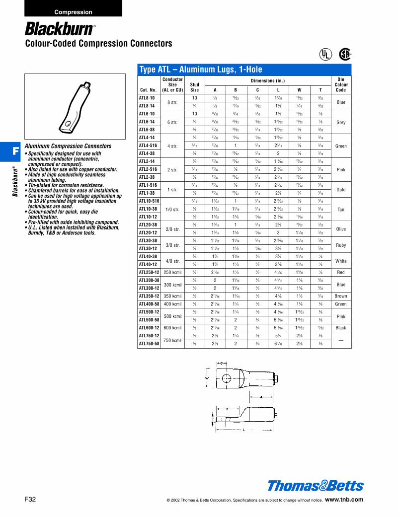
Conductor Dimensions (in.) DieSize Stud Colour
Cat. No. (AL or CU) Size A B C L W T Code
ATL8-10 10 1⁄2 19⁄327⁄32 19⁄32
13⁄323⁄32
ATL8-14 1⁄4 1⁄2 11⁄1611⁄32 13⁄8 7⁄16
3⁄32
ATL6-10 10 25⁄329⁄16
7⁄32 11⁄2 15⁄321⁄8
ATL6-14 1⁄4 25⁄3223⁄32
15⁄32 121⁄3215⁄32
1⁄8
ATL6-38 3⁄8 27⁄3229⁄32
7⁄16 127⁄325⁄8 3⁄32
ATL4-14 1⁄4 27⁄3213⁄16
11⁄32 129⁄325⁄8 3⁄16
ATL4-516 5⁄1627⁄32 1 7⁄16 21⁄16
5⁄8 3⁄16
ATL4-38 3⁄8 27⁄3229⁄32
7⁄16 2 5⁄8 3⁄16
ATL2-14 1⁄4 27⁄3225⁄32
11⁄32 115⁄1623⁄32
3⁄16
ATL2-516 5⁄1627⁄32
7⁄8 7⁄16 211⁄323⁄4 3⁄16
ATL2-38 3⁄8 27⁄3229⁄32
7⁄16 2 1⁄1623⁄32
3⁄16
ATL1-516 5⁄1627⁄32
7⁄8 7⁄16 2 1⁄3223⁄32
3⁄16
ATL1-38 3⁄8 27⁄3229⁄32
7⁄16 23⁄8 3⁄4 3⁄16
ATL10-516 5⁄16 15⁄32 1 7⁄16 217⁄327⁄8 3⁄16
ATL10-38 3⁄8 15⁄32 11⁄167⁄16 219⁄32
7⁄8 3⁄16
ATL10-12 1⁄2 15⁄32 13⁄8 11⁄16 215⁄1615⁄16
3⁄16
ATL20-38 3⁄8 13⁄16 1 7⁄16 25⁄8 31⁄327⁄32
ATL20-12 1⁄2 13⁄16 13⁄8 11⁄16 3 11⁄327⁄32
ATL30-38 3⁄8 111⁄32 11⁄167⁄16 213⁄16 11⁄16
7⁄32
ATL30-12 1⁄2 111⁄32 13⁄8 11⁄16 31⁄8 11⁄167⁄32
ATL40-38 3⁄8 17⁄8 13⁄323⁄8 33⁄4 13⁄16
1⁄4
ATL40-12 1⁄2 17⁄8 11⁄4 1⁄2 3 7⁄8 13⁄161⁄4
ATL250-12 250 kcmil 1⁄2 2 1⁄32 11⁄4 1⁄2 4 1⁄32 19⁄321⁄4 Red
ATL300-38 3⁄8 2 15⁄163⁄8 4 3⁄16 13⁄8 9⁄32
ATL300-12 1⁄2 2 15⁄161⁄2 4 3⁄16 13⁄8 9⁄32
ATL350-12 350 kcmil 1⁄2 211⁄16 15⁄161⁄2 4 7⁄8 11⁄2 5⁄16 Brown
ATL400-58 400 kcmil 5⁄8 211⁄16 11⁄4 1⁄2 415⁄16 15⁄8 3⁄8 Green
ATL500-12 1⁄2 211⁄16 11⁄4 1⁄2 415⁄16 125⁄323⁄8
ATL500-58 5⁄8 211⁄16 2 3⁄4 511⁄16 125⁄323⁄8
ATL600-12 600 kcmil 1⁄2 211⁄16 2 3⁄4 513⁄16 129⁄3211⁄32 Black
ATL750-12 1⁄2 2 7⁄8 11⁄4 1⁄2 51⁄4 21⁄8 3⁄8
ATL750-58 5⁄8 2 7⁄8 2 3⁄4 6 1⁄32 21⁄8 3⁄8
8 str.
6 str.
4 str.
2 str.
1 str.
1/0 str.
2/0 str.
3/0 str.
4/0 str.
300 kcmil
500 kcmil
—
Blue
Pink
White
Ruby
Olive
Pink
Green
Gold
Grey
Blue
Tan
750 kcmil
F32 © 2002 Thomas & Betts Corporation. Specifications are subject to change without notice. www.tnb.com
Type ATL – Aluminum Lugs, 1-Hole
Aluminum Compression Connectors• Specifically designed for use with
aluminum conductor (concentric,compressed or compact).
• Also listed for use with copper conductor.• Made of high conductivity seamless
aluminum tubing.• Tin-plated for corrosion resistance.• Chamfered barrels for ease of installation.• Can be used for high voltage application up
to 35 kV provided high voltage insulationtechniques are used.
• Colour-coded for quick, easy die identification.
• Pre-filled with oxide inhibiting compound.• U.L. Listed when installed with Blackburn,
Burndy, T&B or Anderson tools.
®
®
Colour-Coded Compression Connectors
Compression
F
Blac
kbur
n®
412031.F01 BB 3/6 3/14/03 8:30 AM Page 32

© 2002 Thomas & Betts Corporation. Specifications are subject to change without notice. www.tnb.com F33
Aluminum Compression Connectors• Specifically designed for use with
aluminum conductor (concentric,compressed or compact).
• Also listed for use with copper conductor.• Made of high conductivity seamless
aluminum tubing.• Tin-plated for corrosion resistance.• Chamfered barrels for ease of installation.• Can be used for high voltage application up
to 35 kV provided high voltage insulationtechniques are used.
• Colour-coded for quick, easy dieidentification.
• Pre-filled with oxide inhibiting compound.• U.L. Listed when installed with Blackburn,
Burndy, T&B or Anderson tools.
®
®
Type ASP – Aluminum SplicesCat. No. Conductor Size (AL or CU) Length L (in.) Die Colour Code
ASP8 8 str. 11⁄4 BlueASP6 6 str. 15⁄8 GreyASP4 4 str. 17⁄8 GreenASP2 2 str. 17⁄8 PinkASP1 1 str. 2 3⁄8 GoldASP10 1/0 str. 2 3⁄8 TanASP20 2/0 str. 2 1⁄2 OliveASP30 3/0 str. 27⁄8 RubyASP40 4/0 str. 3 3⁄4 WhiteASP250 250 kcmil 4 RedASP300 300 kcmil 4 BlueASP350 350 kcmil 37⁄8 BrownASP400 400 kcmil 47⁄8 GreenASP500 500 kcmil 5 PinkASP600 600 kcmil 51⁄8 BlackASP750 750 kcmil 53⁄8 —ASP1000 1000 kcmil 6 —
L
Conductor Dimensions (in.) DieSize Stud Colour
Cat. No. (CU) Size A B C D L W T Code
ATL102-38 1/0 str. 3⁄8 15⁄32 2 1⁄163⁄8 1 319⁄32
7⁄8 3⁄16
ATL102 1str. 13⁄16 3 1⁄2 13⁄4 49⁄1615⁄16
3⁄16
ATL202 2/0 str. 13⁄16 3 3⁄8 3⁄4 13⁄4 5 31⁄327⁄32 Olive
ATL302 3/0 str. 111⁄32 3 3⁄8 3⁄4 13⁄4 5 5⁄32 11⁄167⁄32 Ruby
ATL402 4/0 str. 17⁄8 3 1⁄2 13⁄4 5 5⁄8 13⁄161⁄4 White
ATL2502 250 kcmil 2 1⁄32 3 1⁄2 13⁄4 525⁄32 19⁄321⁄4 Red
ATL3002 300 kcmil 2 3 1⁄2 13⁄4 5 7⁄8 13⁄8 9⁄32 Blue
ATL3502 350 kcmil 2 11⁄16 3 1⁄2 13⁄4 69⁄16 11⁄2 5⁄16 Brown
ATL4002 400 kcmil 2 11⁄16 3 1⁄2 13⁄4 611⁄16 15⁄8 3⁄8 Green
ATL5002 500 kcmil 2 11⁄16 3 1⁄2 13⁄4 611⁄16 125⁄323⁄8 Pink
ATL6002 600 kcmil 2 11⁄16 3 1⁄2 13⁄4 613⁄16 129⁄3211⁄32 Black
ATL7502 750 kcmil 27⁄8 3 1⁄2 13⁄4 7 1⁄8 2 1⁄8 3⁄8 —
Aluminum Compression Connectors• Specifically designed for use with
aluminum conductor (concentric,compressed or compact).
• Also listed for use with copper conductor.• Made of high conductivity seamless
aluminum tubing.• Tin-plated for corrosion resistance.• Chamfered barrels for ease of installation.• Can be used for high voltage application up
to 35 kV provided high voltage insulationtechniques are used.
• Colour-coded for quick, easy dieidentification.
• Pre-filled with oxide inhibiting compound.• U.L. Listed when installed with Blackburn,
Burndy, T&B or Anderson tools.
1/0 str. Tan
1⁄2
Colour-Coded Compression Connectors
Type ATL – Aluminum Lugs, 2-Hole
Compression
F
Blackburn®
412031.F01 BB 3/6 3/14/03 8:30 AM Page 33
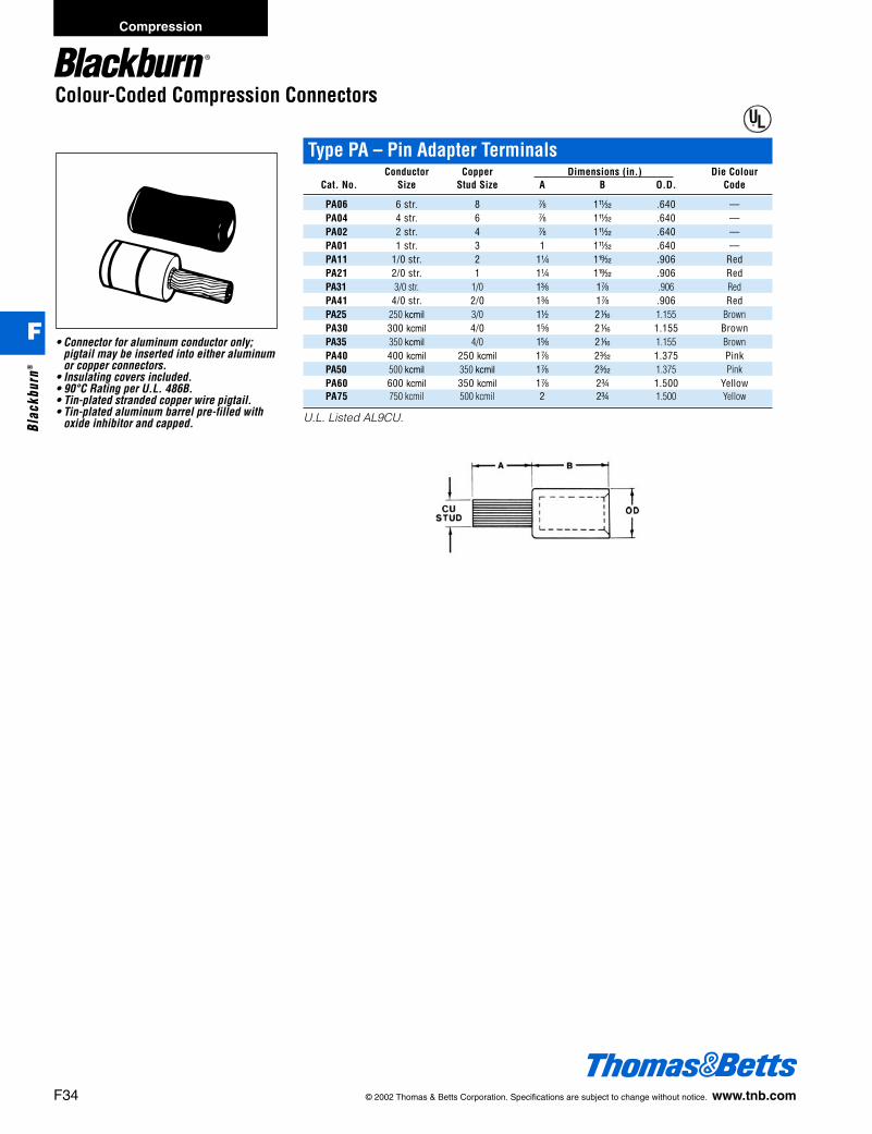
Colour-Coded Compression Connectors
• Connector for aluminum conductor only;pigtail may be inserted into either aluminumor copper connectors.
• Insulating covers included.• 90°C Rating per U.L. 486B.• Tin-plated stranded copper wire pigtail.• Tin-plated aluminum barrel pre-filled with
oxide inhibitor and capped.
®
Type PA – Pin Adapter TerminalsConductor Copper Dimensions (in.) Die Colour
Cat. No. Size Stud Size A B O.D. Code
PA06 6 str. 8 g 1X .640 —PA04 4 str. 6 g 1X .640 —PA02 2 str. 4 g 1X .640 —PA01 1 str. 3 1 1X .640 —PA11 1/0 str. 2 1b 1x .906 RedPA21 2/0 str. 1 1b 1x .906 RedPA31 3/0 str. 1/0 1c 1g .906 RedPA41 4/0 str. 2/0 1c 1g .906 RedPA25 250 kcmil 3/0 1d 2h 1.155 BrownPA30 300 kcmil 4/0 1e 2h 1.155 BrownPA35 350 kcmil 4/0 1e 2h 1.155 BrownPA40 400 kcmil 250 kcmil 1g 2p 1.375 PinkPA50 500 kcmil 350 kcmil 1g 2p 1.375 PinkPA60 600 kcmil 350 kcmil 1g 2f 1.500 YellowPA75 750 kcmil 500 kcmil 2 2f 1.500 Yellow
U.L. Listed AL9CU.
F34 © 2002 Thomas & Betts Corporation. Specifications are subject to change without notice. www.tnb.com
Compression
F
Blac
kbur
n®
412031.F01 BB 3/6 3/14/03 8:30 AM Page 34
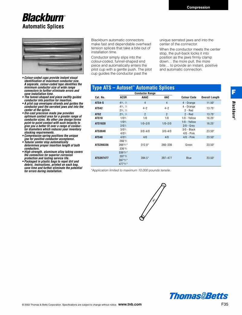
© 2002 Thomas & Betts Corporation. Specifications are subject to change without notice. www.tnb.com F35
Automatic Splices
• Colour-coded caps provide instant visualidentification of maximum conductor size.A separate, colour-coded tape identifies theminimum conductor size of wide rangeconnectors to further eliminate errors andsave installation time.
• The funnel-shaped end piece swiftly guides conductor into position for insertion.
• A pilot cup envelopes strands and guides theconductor past the serrated jaws and into thecenter of the splice.
• Die-cast precision made jaw providesoptimum contact area for a greater range ofconductor sizes. No other jaw design formspoint-to-point contact with such tenacity togive you a better fit over a range of conduc-tor diameters which reduces your inventorystocking requirements.
• Compression spring positions the uniquejaw for positive conductor acceptance.
• Tubular center stop automaticallydetermines proper insertion length of bothconductors.
• High strength, aluminum alloy tubing coversthe connection for superior corrosionprotection and lasting service life.
• Packaged in plastic bags to repel dirt anddebris. Instructions, printed on each bag,save time and further eliminate the potentialfor errors during installation.
Type ATS – Autoset™ Automatic SplicesConductor Range
Cat. No. ACSR AAAC AAC Colour Code Overall Length
ATS4-S 46⁄1, 7⁄1 4 4 4 - Orange 11.50"
ATS42 46⁄1, 7⁄1 4–2 4–2 4 - Orange 13.75"26⁄1, 7⁄1 2 - Red
ATS2 26⁄1, 7⁄1 2 2 2 - Red 13.75"ATS10 1/06⁄1 1/0 1/0 1/0 - Yellow 16.25"
ATS1020 1/06⁄1 1/0–2/0 1/0–2/0 1/0 - Yellow 16.25"2/07⁄1 2/0 - Grey
ATS3040 3/06⁄1 3/0–4/0 3/0–4/0 3/0 - Black 23.50"4/06⁄1 4/0 - Pink
ATS40 4/06⁄1 4/0 4/0 4/0 - Pink 23.50"26618⁄1
ATS266336 26626⁄7* 312.8* 266–336 Green 23.50"33618⁄1
33626⁄7*
ATS397477 39718⁄1 394.5* 397–477 Blue 23.50"39726⁄7*47718⁄1*
*Application limited to maximum 10,000 pounds tensile.
Blackburn automatic connectorsmake fast and dependable overheadtension splices that take a bite out ofinstallation time.Conductor simply slips into thecolour-coded, funnel-shaped endpiece and automatically enters thepilot cup with a gentle push. The pilotcup guides the conductor past the
unique serrated jaws and into thecenter of the connector.When the conductor meets the centerstop, the pull-back locks it intoposition as the jaws firmly clampdown… the more pull, the morebite… to provide an instant, positiveand automatic connection.
Compression
F
Blackburn®
412031.F01 BB 3/6 3/14/03 8:30 AM Page 35

Automatic Deadends
• Used for deadending ACSR, AAC, and AAACconductors.
• Complete with galvanized steel clevis pinand stainless steel cotter pin for use withstandard deadend suspension insulators.
• Breaking strength exceeds 90% of ratedstrength of conductor up to 10,000 lb.maximum.
Blackburn’s automatic deadend fea-tures the same innovative jaw designas the field-proven Blackburn AutosetType ATS automatic tension splice.The Autoset Type ATD automatic ten-sion deadend accepts ACSR, AAC,and AAAC conductors. It’s range-tak-ing capability helps take a bite out ofinventory costs because the five sizesof Autoset replace eight sizes of otherbrands. Installation of the newAutoset deadend is fast and easy,thus reducing maintenance costs aswell as reducing inventory.• Colour-coded caps provide instantvisual identification of maximum con-ductor size. A separate, colour-codedtape identifies the minimum conductor size of a wide rangeconnectors to further eliminate errorsand save installation time.• The funnel-shaped end piece swiftly
guides conductor into position forinsertion.• A pilot cup envelopes strands andguides the conductor past theserrated jaws.• Die-cast precision-made jawsprovide optimum contact area for agreater range of conductor sizes.• The jaws and the I.D. of the tube arecoated with a special microcrystallinebased inhibitor/lubricant which sealsthe connection and provides a highpressure lubricant for long term con-tinuous performance.• The deadends are provided withfactory installed end caps to excludeforeign material.• Compression spring positions theunique jaw for positive conductoracceptance.
Type ATD-ZB – Autoset™ Stainless Steel BailConductor Range Approximate Dimensions (in.)
Cat. No. ACSR AAAC AAC Colour Code A B C
ATD42ZB 46⁄1, 7⁄1 4 4 4 - Orange 1213⁄16 73⁄16 51⁄1626⁄1, 7⁄1 2 2 2 - Red
ATD1020ZB 1/06⁄1 1/0 1/0 1/0 - Yellow 141⁄2 9 415⁄162/06⁄1 2/0 2/0 2/0 - Grey
ATD3040ZB 3/06⁄1 3/0 3/0 3/0 - Black 203⁄4 113⁄4 81⁄24/06⁄1 4/0 4/0 4/0 - Pink
ATD266336ZB 26618⁄1 266 266 Green 203⁄4 113⁄4 81⁄233618⁄1 336 336
ATD397477ZB 39718⁄1 397 397 Blue 203⁄4 113⁄4 81⁄247718⁄1 477 477
AB C
F36 © 2002 Thomas & Betts Corporation. Specifications are subject to change without notice. www.tnb.com
Compression
F
Blac
kbur
n®
412031.F01 BB 3/6 3/14/03 8:30 AM Page 36
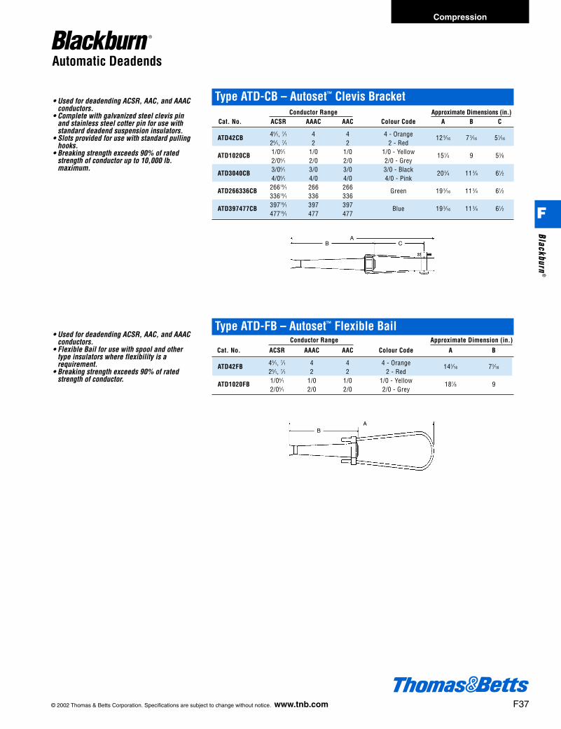
© 2002 Thomas & Betts Corporation. Specifications are subject to change without notice. www.tnb.com F37
Automatic Deadends
• Used for deadending ACSR, AAC, and AAACconductors.
• Complete with galvanized steel clevis pinand stainless steel cotter pin for use withstandard deadend suspension insulators.
• Slots provided for use with standard pullinghooks.
• Breaking strength exceeds 90% of ratedstrength of conductor up to 10,000 lb.maximum.
Type ATD-CB – Autoset™ Clevis BracketConductor Range Approximate Dimensions (in.)
Cat. No. ACSR AAAC AAC Colour Code A B C
ATD42CB 46⁄1, 7⁄1 4 4 4 - Orange 12 9⁄16 7 3⁄16 51⁄1626⁄1, 7⁄1 2 2 2 - Red
ATD1020CB 1/06⁄1 1/0 1/0 1/0 - Yellow 151⁄4 9 53⁄82/06⁄1 2/0 2/0 2/0 - Grey
ATD3040CB 3/06⁄1 3/0 3/0 3/0 - Black 203⁄4 11 3⁄4 61⁄24/06⁄1 4/0 4/0 4/0 - Pink
ATD266336CB 26618⁄1 266 266 Green 19 3⁄16 11 3⁄4 61⁄233618⁄1 336 336
ATD397477CB 39718⁄1 397 397 Blue 19 3⁄16 11 3⁄4 61⁄247718⁄1 477 477
• Used for deadending ACSR, AAC, and AAACconductors.
• Flexible Bail for use with spool and othertype insulators where flexibility is arequirement.
• Breaking strength exceeds 90% of ratedstrength of conductor.
AB C
AB
Type ATD-FB – Autoset™ Flexible BailConductor Range Approximate Dimension (in.)
Cat. No. ACSR AAAC AAC Colour Code A B
ATD42FB 46⁄1, 7⁄1 4 4 4 - Orange 143⁄16 73⁄1626⁄1, 7⁄1 2 2 2 - Red
ATD1020FB 1/06⁄1 1/0 1/0 1/0 - Yellow 187⁄8 92/06⁄1 2/0 2/0 2/0 - Grey
Compression
F
Blackburn®
412031.F01 BB 3/6 3/14/03 8:30 AM Page 37

Service Wedge Clamps
TYPE W
• For dead-ending self-supporting drop wire.• Saves conductor—drop wire may be cut to
exact length.• Can be attached to bare neutral at any point
in the span.• Adjustments in drop wire sag are easily
made.• Grips ACSR, AAAC, or aluminum conductor.
D
L
• For use on copper neutral• Stainless steel wedge and slider
“FC” Flexible Bail(Bail Length - 11d”)
Type W – Aluminum Service Wedge Clamps for use with ACSR, Aluminum, AAAC ConductorConductor Range Dimensions Typical Tensile Values
Cat. No. Description ACSR AL AAAC D L Conductor Value (lb.)
W62-1 W-1 Series 2—6 1 str.— 2—6 23⁄8 12 2 6 x 1 ACSR 1200W62-1FC Aluminum 6 sol. flex. 171⁄2
W20-1 Wedge 1/0—4 2/0 str.— 1/0—4 23⁄8 121⁄2 1/0 6 x 1 ACSR 1800W20-1FC and 2 sol. flex. 181⁄2W40-1* Slider 4/0—2/0 4/0 str.— 4/0—2/0 23⁄8 123⁄4 4/0 6 x 1 ACSR 1900
W40-1FC* 2/0 sol. flex. 181⁄2W62-1B W-1B Series 2—6 1 str.— 2—6 23⁄8 12 2 6 x 1 ACSR 1200
W62-1BFC For extremely 6 sol. flex. 171⁄2W20-1B corrosive areas. 1/0—4 2/0 str.— 1/0—4 23⁄8 121⁄2 1/0 6 x 1 ACSR 1800
W20-1BFC Iridited Aluminum 2 sol. flex. 181⁄2W40-1B* Wedge 4/0—2/0 4/0 str.— 4/0—2/0 23⁄8 123⁄4 4/0 6 x 1 ACSR 1900
W40-1BFC* and Slider 2/0 sol. flex. 181⁄2
* W40 series clamps rated 850 lb. ultimate tension for 1/0 ACSR, AL, or AAAC.
Type W – Stainless Steel Wedge ClampsConductor Range Dimensions Typical Tensile Values
Cat. No. Stranded Solid D L Conductor Value (lb.)
W62D* 2—6 1—6 23⁄8 12 2—7 str. AAC 1300
Rigid Stainless Steel Bail(Bail Length - 6d”)
F38 © 2002 Thomas & Betts Corporation. Specifications are subject to change without notice. www.tnb.com
Compression
F
Blac
kbur
n®
412031.F01 BB 3/6 3/14/03 8:30 AM Page 38