compressed air dryers - imi precisioncdn.norgren.com/pdf/27dryers.pdf · features and benefits...
TRANSCRIPT

Littleton, CO USA Phone 303-794-2611 Fax 303-795-9487 ALE-27-1
Section 27
Features and Benefits of Dry Compressed Air . . . . . . . . . . . . . . . ALE-27-2D11 Series Refrigerated Compressed Air Dryers. . . . . . . . . . . . . . ALE-27-4D10 Series Air Cooled Refrigerated
Compressed Air Dryers . . . . . . . . . . . . . . . . . . . . . . . . . . . . . . . ALE-27-6D10 Series Water Cooled Refrigerated Compressed Air Dryers . . ALE-27-8D50 Series Compact Heatless Regenerative
Compressed Air Dryers . . . . . . . . . . . . . . . . . . . . . . . . . . . . . . ALE-27-10D51 Series Heatless Regenerative Compressed Air Dryers . . . . ALE-27-12D60 Series Externally Heated Regenerative
Compressed Air Dryers . . . . . . . . . . . . . . . . . . . . . . . . . . . . . . ALE-27-16D70 Series Blower Purge Regenerative
Compressed Air Dryers . . . . . . . . . . . . . . . . . . . . . . . . . . . . . . ALE-27-18W74D Excelon® Desiccant Compressed Air Dryers . . . . . . . . . . ALE-27-20Product Numbering System . . . . . . . . . . . . . . . . . . . . . . . . . . . . . ALE-27-22Technical Data (Selecting and Sizing) . . . . . . . . . . . . . . . . . . . . . ALE-27-28
Compressed Air DryersCompressor room refrigerated,heated and heatless regenerativedryers and accessories.
D11 Series RefrigeratedCompressed Air Dryers
D10 Series Air or WaterCooled RefrigeratedCompressed Air Dryers
D50 Series CompactHeatless RegenerativeCompressed Air Dryers
D51 Series HeatlessRegenerativeCompressed Air Dryers
D60 Series ExternallyHeated RegenerativeCompressed Air Dryers
D70 Series Blower PurgeRegenerative CompressedAir Dryers
W74D Excelon® 74Desiccant Compressed Air Dryers

Features and Benefits
Littleton, CO USA Phone 303-794-2611 Fax 303-795-9487ALE-27-2
Why dry your compressed air?
Because wet air costs you money. Moisture-laden air is not compatiblewith a clean, efficient, smooth-running system. Understanding how waterenters a compressed air system will help illustrate the extent of theproblem.
When air is compressed the moisture and impurities contained in theambient atmosphere are also compressed. This results in a highconcentration of moisture and impurities in the receiver. For example, at75°F ambient temperature and 75% relative humidity, a 100 scfmcompressor will take in the equivalent of 18 gallons of water, as vapor ina day.
The elevated temperature of the compressed air contributes to theproblem. The higher the air temperature, the greater its capacity forholding water vapor. Conversely, as the air temperature is lowered, itscapacity for holding water vapor is decreased. An after-cooler positionedimmediately after the compressor will allow some of the moisture to bereleased as condensate, but does not cool the air sufficiently to removeenough of the water vapor to protect the entire system.
Air line filters installed downstream will satisfactorily remove solidimpurities and water in liquid form, but are not able to remove watervapor. As the air cools downstream the water is released, introducing anumber of moisture related problems to the system.
What happens when moisture invades your compressed airsystem?
Water in a compressed air system attacks lubricants injected into thesystem to protect air tools and cylinders. This reduces operationalefficiency, shortens scheduled maintenance intervals and ultimatelyresults in premature tool failure. Air blow-offs become a quick rinse andpainting processes are spoiled because of condensate mixing with thepaint spray.
Equally as serious are the long-term effects of water in pneumaticsystems. Oxidation of metal piping soon occurs. This threatens theintegrity of the system by weakening the walls of the pipe. Rust flakesform, break-off from the walls, and are scattered throughout the piping,introducing an entirely new contaminant to the system.
Water settling in low spots in the line or clinging to pipe walls acts like amagnet collecting solid contaminants and oil droplets. This mixture cansolidify on the pipe walls restricting flow, causing additional pressuredrop. Oil and water emulsion can form. This is a gummy substance thatfouls air motors and causes other moving parts to stick.
Did You Know?
A 100 scfm compressor operating in 75°Ftemperature and 75% relative humidity ambientconditions will take in the equivalent of 18 gallons ofwater, as vapor, in a day.
The higher the air temperature, the greater itscapacity for holding water.
Equally as serious are the long-term effects of waterin compressed air systems.
The ultimate result in a systemwhere moisture problems arenot addressed is pipe cloggedwith rust and scale. The cost ofa compressed air dryer is aninvestment in the longevity ofthe system.

Features and Benefits
Littleton, CO USA Phone 303-794-2611 Fax 303-795-9487 ALE-27-3
D11 Refrigerated Dryer Operation
Refrigerated Compressed Air Dryer OperationNorgren refrigerated compressed air dryers remove moisture fromcompressed air systems by lowering the temperature of the compressedair to condense the water vapor. A cool drink on a hot day illustrates thisprocess. Warm, moist air comes in contact with the cold glass causingwater droplets to condense from the ambient air and form on the outsideof the glass. Refrigerated dryers use a heat exchanger and refrigerantcircuit to lower the temperature of the compressed air to initiatecondensation. The condensate generated in the heat exchanger is thendirected to a moisture separator and drained away.
D11 Heat Exchangers Operation5 through 40 scfm
D11 dryers within this size range are equipped with a spiral tube-in-tubeheat exchanger. This design provides maximum heat exchange efficiencywith minimum pressure drop. The spiral design generates a helicalpattern of air flow against the cooled tube surface to provide maximumheat transfer.
As the water vapor condenses on the spiral tube surface it is directed tothe moisture separator at high velocity. The spiral air flow patterneliminates the sharp angled surfaces that collect contaminants. Thisprovides a continuous cleaning action to retard oil and varnish buildupthat can clog exchangers, resulting in pressure loss and reducedefficiency. Note: 30 and 40 scfm dryer operation similar to that shownbelow with the incorporation of an air-to-air heat exchanger.
50 through 200 scfm
D11 dryers within this size range are equipped witha brazed plate heat exchanger. These light-weight,compact, plate-type heat exchangers are noted fortheir excellent thermal efficiency. Air-to-air and air-to-refrigerant heat exchanges occur within the sameunit, eliminating the need for multiple heatexchangers.
Corrugated stainless steel plates brazed with copperalloy into a honeycomb system create counter flowpaths in both the air-to-air and air-to-refrigerantsides. Compressed air and refrigerant are securelycontained in their separate channels to avoidleakage. The smooth flow path design provides acontinuous cleaning action to retard oil and varnishbuildup. These heat exchangers can be back-flushedfor thorough cleaning when necessary.
Inlet Air
Refrigerant
Dryer Pressure Atmospheric Drying Media Power Initial Pre After MaintenanceType Dew Point Dew Point Replacement Consumption Cost Filters Filters Cost
Refrigerated 35°F (2°C) 74°F (23°C) Nil For Medium General purpose None Regularrefrigeration and coalescing maintenance
motor of refrigeration
Regenerative -40°F (-40°C) -70°F (-57°C) Infrequent For drying High General purpose Coalescing SmallDesiccant desicant and coalescing
Deliquescent 50°F (10°C) 5°F (-15°C) Regularly, Nil Low General purpose Coalescing Rechargingminimum and container6 months coalescing
Dryer Comparison

Littleton, CO USA Phone 303-794-2611 Fax 303-795-9487
D11 Series Dryers
● Continuous compressor operation adds years tocompressor life, and maintains a 35° to 42° (2° to6°C) pressure dew point per ANSI/B93.45M.
● Norgren’s D11 Series Dryers offer a wide range ofaccessories such as gauges, ambient filters,automatic timer drain, and many others to meetchanging conditions.
● All Norgren dryers are warranted to be free fromdefects in materials and workmanship for a period oftwo years from date of manufacture.
● Norgren’s quality dryer construction is unsurpassedin the industry.
D11 Series RefrigeratedCompressed Air Dryers
SpecificationsRefrigerant: R-134aMaximum Working Pressure: 250 psigMaximum Inlet Air Temperature: 120°FAmbient Temperature Range: 50° to 110°F
Standard EquipmentMoisture separator/automatic drain16'' power cord (5 through 75 scfm units)Electrical terminal block (100 through 200 scfm units)
Optional EquipmentOn/Off switchPower on lightHigh temperature warning lightRefrigerant suction pressure gaugeRefrigerant discharge pressure gauge (100 through 200 scfm units)6' power cord (5 through 75 scfm units)Drain tube kitInlet air temperature gauge (30 through 200 scfm units)Outlet air temperature gauge (100 through 200 scfm units)Inlet air pressure gauge (100 through 200 scfm units)Outlet air pressure gauge (30 through 200 scfm units)
ALE-27-4
AccessoriesAutomatic timer drain valveBypass valving (5 and 10 scfm units)Pre-filtersAfterfilters
Model VoltageNumber (volt-ac/hz/phase)
D11-1__-0005 thru 115-60-1/100-50-1D11-1__-0150D11-2__-0005 &0010 220-60-1/200-50-1D11-2__-0040 thru 0200D11-3__-0200 230/208-60-3D11-4__-0200 460-60-3D11-6__-0005 thru
240/220-50-1D11-6__-0200
Electrical Data for Air Cooled Dryers
Dryer Flow, Power Ratings, and Weights
Nominal Model ∆P Compressor TotalDryer Number (psid) Hp. Weight Flow lbs. (kg)
5 D11-___-0005 1.0 1/6 50 (23)10 D11-___-0010 3.8 1/6 50 (23)15 D11-___-0015 0.7 1/5 53 (24)20 D11-___-0020 1.0 1/5 53 (24)30 D11-___-0030 1.4 1/5 90 (41)40 D11-___-0040 2.4 1/4 90 (41)50 D11-___-0050 3.5 1/4 90 (41)75 D11-___-0075 3.5 1/2 121 (55)100 D11-___-0100 2.7 1/2 185 (84)130 D11-___-0130 2.8 3/4 210 (95)150 D11-___-0150 3.0 3/4 210 (95)200 D11-___-0200 4.3 1 221 (100)

D11 Series Refrigerated Compressed Air Dryers
Littleton, CO USA Phone 303-794-2611 Fax 303-795-9487 ALE-27-5
90°F (32°C) Inlet Air Temp 100°F (38°C) Inlet Air Temp. 110°F (43°C) Inlet Air Temp.Model 50 100 150 200 50 100 150 200 50 100 150 200
Number* psig psig psig psig psig psig psig psig psig psig psig psig
D11-___-0005 4.40 5.50 5.94 6.16 4.00 5.00 5.40 5.60 3.56 4.45 4.80 4.98(2) (3) (3) (3) (2) (2) (3) (3) (2) (2) (2) (2)
D11-___-0010 8.80 11.00 11.88 12.32 8.00 10.00 10.80 11.20 7.12 8.90 9.61 9.96(4) (5) (6) (6) (4) (5) (5) (5) (3) (4) (5) (5)
D11-___-0015 13.20 16.50 17.82 18.48 12.00 15.00 16.20 16.80 10.68 13.35 14.41 14.95(6) (8) (8) (9) (6) (7) (8) (8) (5) (6) (7) (7)
D11-___-0020 17.60 22.00 23.76 24.64 16.00 20.00 21.60 22.40 14.24 17.80 19.22 19.93(8) (10) (11) (12) (8) (9) (10) (11) (7) (8) (9) (9)
D11-___-0030 26.40 33.00 35.64 36.96 24.00 30.00 32.40 33.60 21.36 26.70 28.83 29.90(12) (16) (17) (17) (11) (14) (15) (16) (10) (13) (14) (14)
D11-___-0040 35.20 44.00 47.52 49.28 32.00 40.00 43.20 44.80 28.40 35.60 38.44 39.87(17) (21) (22) (23) (15) (19) (20) (21) (13) (17) (18) (19)
D11-___-0050 44.00 55.00 59.40 61.60 40.00 50.00 54.00 56.00 35.60 44.50 48.06 49.84(21) (26) (28) (29) (19) (24) (25) (26) (17) (21) (23) (23)
D11-___-0075 66.00 82.50 89.10 92.40 60.00 75.00 81.00 84.00 53.40 66.75 72.09 74.76(31) (39) (42) (43) (28) (35) (38) (39) (25) (31) (34) (35)
D11-___-0100 88.00 110.00 118.80 123.20 80.00 100.00 108.00 112.00 71.20 89.00 96.12 99.68(41) (52) (56) (58) (38) (47) (51) (53) (33) (42) (45) (47)
D11-___-0130 114.40 143.00 154.44 160.16 104.00 130.00 140.40 145.60 92.56 115.70 124.95 129.58(54) (67) (73) (75) (49) (61) (66) (68) (44) (54) (59) (61)
D11-___-0150 132.00 165.00 178.20 184.80 120.00 150.00 162.00 168.00 106.80 133.50 144.18 149.52(62) (78) (84) (87) (56) (71) (76) (79) (50) (63) (68) (70)
D11-___-0200 176.00 220.00 237.60 246.40 160.00 200.00 216.00 224.00 142.40 178.00 192.24 199.36(83) (103) (112) (116) (75) (94) (102) (105) (67) (84) (90) (94)
°F (°C) Multiply by60 (16) 1.3470 (21) 1.2780 (27) 1.1990 (32) 1.10100 (38) 1.00110 (43) 0.89
Flow Capacity Selection Chart[scfm (dm3/s) @ 38°F (3°C) Pressure Dew Point, and 100°F (38°C) Ambient Temperature]
* For complete D11 product numbering system see ALE-27-22.
Ambient Temperature Multipliers
A
B
F
CD
E
Drain TubePower CordAccess
G
H
Inlet
Outlet
Dryer Number A B C D E F G Inlet H Outlet
D11-___-0005 14.00 15.13 12.11 1.98 2.0 10.38 3/8'' NPT 3/8'' NPTthru D11-___-0010 (356) (384) (308) (1250) (51) (264)
D11-___-0015 14.00 16.00 14.88 1.98 2.00 10.38 1/2'' NPT 1/2'' NPTthru D11-___-0020 (356) (406) (378) (50) (51) (264)
Dimensions for D11-***-0005 thru D11-***-0020 Refrigerated Air Dryers Inches (mm)
24.88(632)
31.06(788)
30.75(781)
2.24(57)
6.0(152)
Inlet 2'' NPT
Outlet 2'' NPT
21.12(536)
24.63(626)
29.0(737)
Dimensions for D11-***-0150 & D11-***-0200 Refrigerated Air Dryers Inches (mm)
17.73(450)
18.76(477) 13.69
(348)
18.86(479)
1.94(49)
4.0(102)
Drain TubePower CordAccess
Outlet 1'' FPT
Inlet 1'' FPT
Dimensions for D11-***-0030 thru D11-***-0100 Refrigerated Air Dryers Inches (mm)

Littleton, CO USA Phone 303-794-2611 Fax 303-795-9487
D10 Series Dryers
● Refrigerant compressor runs continuously whenpower is applied to the dryer, providing a nearlyconstant dew point at all times
● High efficiency heat exchangers.
● Heat exchangers are modular in design and may bereplaced in the field.
● Hot gas by-pass valve directs hot refrigerant into thecompressor suction line at the exit of the air torefrigerant heat exchanger, permitting constant dewpoint control down to zero air flow.
● Does not need a separate centrifugal type moistureseparator.
Air-Cooled Refrigerated Compressed Air Dryers
SpecificationsRefrigerant: R-22Maximum Working Pressure: 150 psig (10 bar)Maximum Inlet Air Temperature: 120°F (49°C)Ambient Temperature Range:
50° to 110°F (10° to 43°C)
Standard EquipmentDryer running lightHigh suction temperature lightON/OFF switch (control circuit)Air inlet temperature gaugeAir outlet temperature gauge (600 through 2,000 scfm units)Air inlet pressure gauge (600 through 2,000 scfm units)Air outlet pressure gaugeRefrigerant discharge pressure gauge (600 through 2,000 scfm units)Refrigerant analyzer gauge (suction pressure and temperature)Automatic timer drain valveCompressor motor overload protectionCrankcase heaterHigh/Low refrigerant pressure controlLow ambient fan control
Optional EquipmentSix gauge package (250 through 500 scfm units)
Air outlet temperature gaugeAir inlet pressure gaugeRefrigerant discharge pressure gauge
Low or high refrigerant pressure alarmNEMA 4 and NEMA 12 wiring (excludes compressor and fanmotors)Alarm bellHour meterAmbient air filterFlow meterPrefiltersAfterfilters
ALE-27-6
Model PortingD10-__0-0250 - 0500 2'' FPTD10-__0-0600 - 1000 3'' FPTD10-__0-1250 - 2000 4'' FPTDrains – 1/2'' NPT
Air Inlet and Air Outlet Ports Sizes
Model Main ControlNumber Power Power
(volt-ac/hz/phase) (VAC)D10-200-0250 thru 230/208-60-1 230D10-200-0325D10-300-0250 thru 230/208-60-3 230D10-300-2000D10-400-0250 thru 460-60-3 115D10-400-2000D10-500-0400 thru 600/550-60-3 115D10-500-2000D10-600-0250 thru 240/220-50-1 240D10-600-0325D10-700-0250 thru 240/220-50-3 240D10-700-2000D10-800-0250 thru 420/380-50-3 115D10-800-2000
Electrical Data for Air Cooled Dryers
Nominal Model ∆P Compressor TotalDryer Number (psid) Hp. Weight Flow lbs. (kg)250 D10-_00-0250 0.8 1.5 650 (295)325 D10-_00-0325 1.1 2.0 675 (306)400 D10-_00-0400 1.5 3.0 700 (318)500 D10-_00-0500 2.5 3.0 725 (329)600 D10-_00-0600 1.0 3.0 1,250 (567)800 D10-_00-0800 2.0 4.0 1,300 (590)1000 D10-_00-1000 3.0 5.0 1,400 (635)1250 D10-_00-1250 1.6 7.5 1,925 (882)1500 D10-_00-1500 2.0 9.0 1,950 (885)1750 D10-_00-1750 2.8 10.0 2,075 (941)2000 D10-_00-2000 3.5 12.0 2,125 (964)
Dryer Flow, Power Ratings, and Weights

D10 Series Air-Cooled Refrigerated Compressed Air Dryers
Littleton, CO USA Phone 303-794-2611 Fax 303-795-9487 ALE-27-7
90°F (32°C) 100°F (38°C) 110°F (43°C)Inlet Air Temp Inlet Air Temp Inlet Air Temp
Model 50 100 150 50 100 150 50 100 150Number* psig psig psig psig psig psig psig psig psig
D10-_00-0250 265 300 330 210 250 275 163 200 220(125) (141) (155) (99) (118) (129) (77) (94) (103)
D10-_00-0325 344 390 429 273 325 358 211 260 286(162) (183) (202) (128) (153) (168) (99) (122) (134)
D10-_00-0400 424 480 528 336 400 440 260 320 352(199) (226) (248) (158) (188) (207) (122) (150) (165)
D10-_00-0500 530 600 660 420 500 550 325 400 440(249) (282) (310) (197) (235) (259) (153) (188) (207)
D10-_00-0600 636 720 792 504 600 660 390 480 528(299) (338) (372) (237) (282) (310) (183) (226) (248)
D10-_00-0800 848 960 1,056 672 800 880 520 640 704(399) (451) (496) (316) (376) (414) (244) (301) (331)
D10-_00-1000 1,060 1,200 1,320 840 1,000 1,100 650 800 880(498) (564) (620) (395) (470) (517) (306) (376) (414)
D10-_00-1250 1,325 1,500 1,650 1,050 1,250 1,375 810 1000 1,100(623) (705) (776) (494) (588) (646) (381) (470) (517)
D10-_00-1500 1,590 1,800 1,980 1,260 1,500 1,650 975 1,200 1,320(748) (846) (931) (592) (705) (776) (458) (564) (621)
D10-_00-1750 1,855 2,100 2,310 1,470 1,750 1,925 1,140 1,400 1,540(872) (988) (1086) (691) (823) (905) (536) (658) (724)
D10-_00-2000 2,120 2,400 2,640 1,680 2,000 2,200 1,300 1,600 1,760(996) (1128) (1241) (790) (940) (1034) (611) (752) (827)
°F (°C) Multiply by60 (16) 1.3470 (21) 1.2780 (27) 1.1990 (32) 1.10100 (38) 1.00110 (43) 0.89
N
B
CD
E
F
G K LGA
JH
1/2'' hole
J H
M KL
P
1/2" FPTdrain
ElectricalBox
1/2'' hole
Q
Air Outlet
Air Inlet
Dryer Number A B C D E F G H J K L M N P Q
D10-_00-0250 30.00 19.00 54.50 49.13 5.75 15.00 2.00 4.00 8.00 3.00 6.00 12.00 2.00 43.00 23.63thru D10-_00-0500 (762) (483) (1384) (1248) (146) (381) (51) (102) (203) (76) (152) (305) (51) (1092) (600)
D10-_00-0600 33.00 24.00 69.88 61.63 6.38 16.50 3.38 6.75 8.00 3.00 6.00 15.00 2.00 53.50 31.00thru D10-_00-1000 (838) (610) (1775) (1565) (162) (419) (86) (171) (203) (76) (152) (381) (51) (1359) (787)
D10-_00-1250 39.00 24.00 75.88 66.88 7.50 19.50 6.25 12.50 8.00 3.00 6.00 21.00 2.00 65.00 33.00thru D10-_00-2000 (991) (610) (1927) (1699) (191) (495) (159) (318) (203) (76) (152) (533) (51) (1651) (838)
Dimensions for Air-Cooled DryersInches (mm)
Ambient Temperature CorrectionFactor for Air Cooled Dryers
Flow Capacity Selection Chart[scfm (dm3/s) @ 38°F (3°C) Pressure Dew Point, and 100°F (38°C) Ambient Temperature]
* For complete D10 product numbering system see ALE-27-23.

Littleton, CO USA Phone 303-794-2611 Fax 303-795-9487
D10 Series Dryers
● Refrigerant compressor runs continuously whenpower is applied to the dryer, providing a nearlyconstant dew point at all times
● High efficiency heat exchangers.
● Heat exchangers are modular in design and may bereplaced in the field.
● Hot gas by-pass valve directs hot refrigerant into thecompressor suction line at the exit of the air torefrigerant heat exchanger, permitting constant dewpoint control down to zero air flow.
● Does not need a separate centrifugal type moistureseparator.
Water-Cooled Refrigerated Compressed Air Dryers
SpecificationsRefrigerant: R-22Maximum Working Pressure: 150 psig (10 bar)Maximum Inlet Air Temperature: 120°F (49°C)Ambient Temperature Range:
50° to 110°F (10° to 43°C)
Standard EquipmentDryer running lightHigh suction temperature lightON/OFF switch (control circuit)Air inlet temperature gaugeAir outlet temperature gauge (600 through 2,000 scfm units)Air inlet pressure gauge (600 through 2,000 scfm units)Air outlet pressure gaugeRefrigerant discharge pressure gauge (600 through 2,000 scfm units)Refrigerant analyzer gauge (suction pressure and temperature)Automatic timer drain valveCompressor motor overload protectionCrankcase heaterHigh/Low refrigerant pressure controlWater pressure switchWater regulating valve
Optional EquipmentSix gauge package (400 and 500 scfm units)
Air outlet temperature gaugeAir inlet pressure gaugeRefrigerant discharge pressure gauge
Low or high refrigerant pressure alarmNEMA 4 and NEMA 12 wiring (excludes compressor and fan motors)Alarm bellHour meterPrefiltersAfterfilters
ALE-27-8
Model Main ControlNumber Power Power
(VAC) (VAC)D10-301-0400 thru 230/208-60-3 230D10-301-2000D10-401-0400 thru 460-60-3 115D10-401-2000D10-501-0400 thru 600/550-60-3 115D10-501-2000D10-701-0400 thru 240/220-50-3 240D10-701-2000D10-801-0400 thru 420/380-50-3 100D10-801-2000
Electrical Data for Water-Cooled Dryers
Model ∆P Compressor TotalNumber (psid) Hp. Weight
lbs. (kg)
D10-_01-0400 1.8 2.0 700 (318)D10-_01-0500 3.0 3.0 725 (329)D10-_01-0600 1.1 3.0 1,250 (567)D10-_01-0800 2.3 4.0 1,300 (590)D10-_01-1000 3.3 5.0 1,400 (635)D10-_01-1250 1.6 7.5 1,925 (873)D10-_01-1750 3.1 9.0 2,075 (941)D10-_01-2000 3.9 10.0 2,125 (964)
Dryer Flow, Power Ratings, and Weights
Model PortingD10-__1-0400 - 0500 2'' FPTD10-__1-0600 - 1000 3'' FPTD10-__1-1200 - 2000 4'' FPTDrains – 1/2'' NPT
Water Inlet and Water OutletD10-__1-0400 - 0500 1/2'' FPTD10-__1-0600 - 1000 1'' FPT
Air Inlet and Air Outlet Ports Sizes

D10 Series Water-Cooled Refrigerated Compressed Air Dryers
Littleton, CO USA Phone 303-794-2611 Fax 303-795-9487 ALE-27-9
90°F (32°C) 100°F (38°C) 110°F (43°C)Inlet Air Temp Inlet Air Temp Inlet Air Temp
Model 50 100 150 50 100 150 50 100 150Number* psig psig psig psig psig psig psig psig psig
D10-_01-0400 461 522 574 365 435 479 283 348 383(217) (245) (270) (172) (204) (225) (133) (164) (180)
D10-_01-0500 583 660 726 462 550 605 358 440 484(274) (310) (341) (217) (259) (284) (168) (207) (227)
D10-_01-0600 662 756 832 529 630 693 410 504 554(311) (355) (391) (249) (296) (326) (193) (237) (260)
D10-_01-0800 901 1,020 1,122 714 850 935 553 680 748(423) (479) (527) (336) (400) (439) (260) (320) (352)
D10-_01-1000 1,113 1,260 1,386 882 1,050 1,155 683 840 924(523) (592) (651) (415) (494) (543) (321) (395) (434)
D10-_01-1250 1,325 1,500 1,650 1,050 1,250 1,375 810 1,000 1,110(623) (705) (776) (494) (588) (646) (381) (470) (522)
D10-_01-1750 1,950 2,208 2,430 1,545 1,840 2,024 1,196 1,472 1,619(916) (1038) (1142) (726) (865) (951) (562) (692) (761)
D10-_01-2000 2,226 2,520 2,772 1,764 2,100 2,310 1,365 1,680 1,848(1046) (1184) (1303) (829) (987) (1086) (642) (790) (869)
Flow Capacity Selection Chart[scfm (dm3/s) @ 38°F (3°C) Pressure Dew Point, 100°F (38°C) Ambient Temperature, and 85°F Inlet Water Temperature]
B
CD
E
F
G K LGA JH J H
M KL
1/2'' hole 1/2'' hole
1/2" FPTdrain
ElectricalBox
Water Outlet1/2" FPT
Water Inlet1/2" FPT
RS
Air Outlet
Air Inlet
Q
P
Dryer Number A B C D E F G H J K L M N P Q R S
D10-_01-0400 30.00 19.00 54.50 49.13 5.75 15.00 2.00 4.00 8.00 3.00 6.00 12.00 2.00 43.00 23.63 15.63 10.63thru D10-_01-0500 (762) (483) (1384) (1248) (146) (381) (51) (102) (203) (76) (152) (305) (51) (1092) (600) (397) (270)
D10-_01-0600 33.00 24.00 69.88 61.63 6.38 16.50 3.38 6.75 8.00 3.00 6.00 15.00 2.00 53.50 31.00 14.00 10.00thru D10-_01-1000 (838) (610) (1775) (1565) (162) (419) (86) (171) (203) (76) (152) (381) (51) (1359) (787) (356) (254)
D10-_01-1250 39.00 24.00 75.88 66.88 7.50 19.50 6.25 12.50 8.00 3.00 6.00 21.00 2.00 65.00 33.00 14.00 10.00thru D10-_01-2000 (991) (610) (1927) (1699) (191) (495) (159) (318) (203) (76) (152) (533) (51) (1651) (838) (356) (254)
Dimensions for Water-Cooled DryersInches (mm)
* For complete D10 product numbering system see ALE-27-23.

Littleton, CO USA Phone 303-794-2611 Fax 303-795-9487
D50 Series Dryers
● The twin desiccant-packed towers alternateoperation continuously to provide ultra-dry air forcritical applications.
● Timer controlled shuttle valves direct thecompressed air into the active tower for drying.
● Calibrated needle valve adjusts purge flow to actualoutlet flow and pressure conditions.
● Overlapping cycle times provide constantdownstream pressure and dew point.
Compact Heatless RegenerativeCompressed Air Dryers
SpecificationsInlet Air Pressure: 60 to 150 psig (4 to 10 bar) Ambient Temperature Range: 35° to 110°F (2° to 43°C)Outlet Pressure Dew point: -40°F (-40°C)
Optional: -66°F (54°C) Inlet and Outlet ports: 1/2-14 NPTFElectrical Requirements: 115 v-60 hz -1 ph, 230 v-60 hz-1ph,
240/220 V-50 hz-1 ph, 12 or 24 VDCPurge Air Consumption for Regeneration: 20%Power Consumption: 10 WattsSound Level:
Running: 56 dBaSwitching: 74 dBa
Materials of ConstructionTower and Body: AluminumElastomers: Nitrile and PolyurethaneDesiccant: Activated Alumina
Standard EquipmentSwitching valvesPurge valvesPurge control valvePurge mufflersDesiccant packed towersElectric timerSix-foot power cordMoisture indicator (standard unit only)Inlet pressure gauge (standard unit only)Tower pressure indicators (standard unit only)Tower pressure indicator color code:
Green: Tower is at line pressure in drying cycleBlack: Tower is slightly above atmospheric pressure
and in regenerative cycle
Optional Equipment-66°F (-54°C) outlet pressure dew pointNEMA 7 rating (hazardous location)Prefilters (recommended)Afterfilters (recommended)
ALE-27-10
Model Inlet Flow Outlet Flow TotalNumber Range Range Weight
(scfm @ 100 psig) (scfm @ 100 psig) lbs. (kg)
D50-___-0010 2 to 10 1.5 to 7.7 17 (8)D50-___-0025 8 to 25 6.1 to 19.3 24 (11)D50-___-0050 20 to 50 15.2 to 38.5 44 (20)
Inlet and Outlet Flow Capacities, and Weights

D50 Series Compact Heatless Regenerative Compressed Air Dryers
Littleton, CO USA Phone 303-794-2611 Fax 303-795-9487 ALE-27-11
A
D
C
B
F
E
IN
OUT
Moisture Indicator
Purge Adjustment
OUT
IN
H
J
G
Dryer Number* A B C D E F G H J
D50-___0010 18.50 10.00 9.00 7.06 1.25 4.90 0.44 4.62 5.25(469.90) (254.00) (228.60) (179.32) (31.75) (124.46) (11.18) (117.35) (133.35)
D50-___-0025 22.25 10.00 9.00 7.06 1.25 4.90 0.44 4.62 5.25(565.15) (254.00) (228.60) (179.32) (31.75) (124.46) (11.18) (117.35) (133.35)
D50-___-0050 27.70 10.00 9.00 7.06 1.25 4.90 0.44 4.62 5.25(703.58) (254.00) (228.60) (179.32) (31.75) (124.46) (11.18) (117.35) (133.35)
Dimensions for D50 Heatless Regenerative Compressed Air DryersInches (mm)
* For complete D50 product numbering system see ALE-27-24.
Littleton, CO USA Phone 303-794-2611 Fax 303-795-9487
D51 Series Dryers
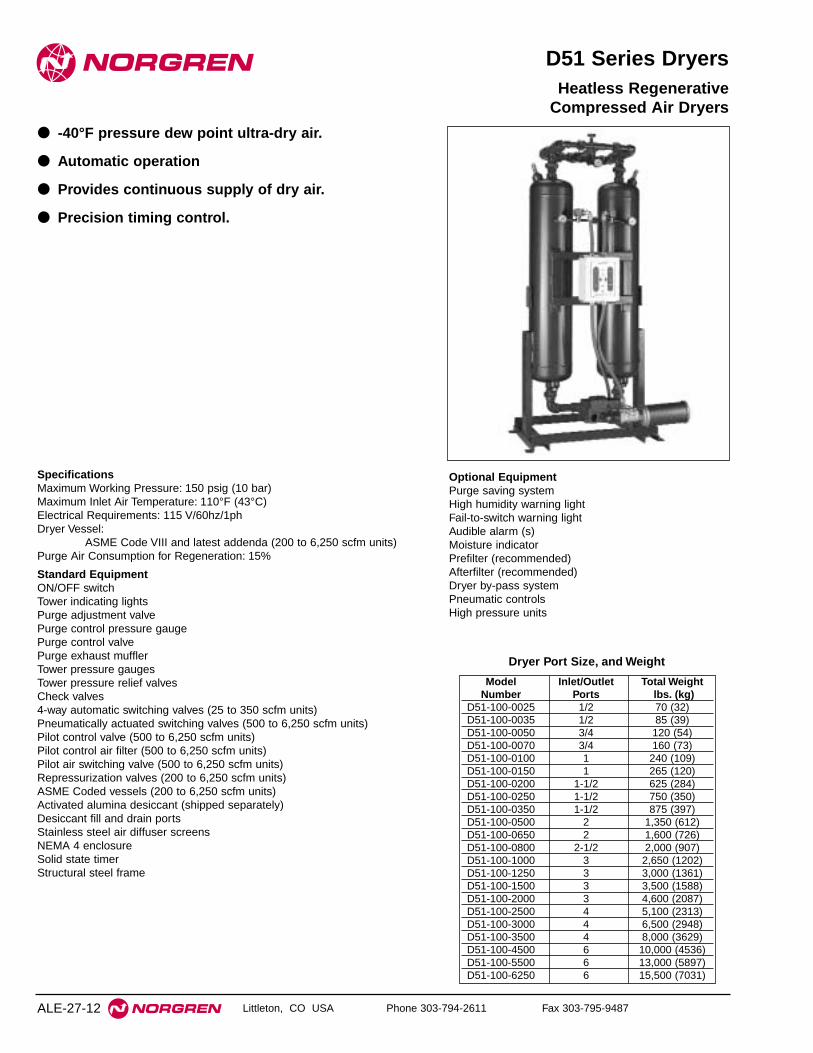
● -40°F pressure dew point ultra-dry air.
● Automatic operation
● Provides continuous supply of dry air.
● Precision timing control.
Heatless Regenerative Compressed Air Dryers
SpecificationsMaximum Working Pressure: 150 psig (10 bar)Maximum Inlet Air Temperature: 110°F (43°C)Electrical Requirements: 115 V/60hz/1phDryer Vessel:
ASME Code VIII and latest addenda (200 to 6,250 scfm units)Purge Air Consumption for Regeneration: 15%
Standard EquipmentON/OFF switchTower indicating lightsPurge adjustment valvePurge control pressure gaugePurge control valvePurge exhaust mufflerTower pressure gaugesTower pressure relief valvesCheck valves4-way automatic switching valves (25 to 350 scfm units)Pneumatically actuated switching valves (500 to 6,250 scfm units)Pilot control valve (500 to 6,250 scfm units)Pilot control air filter (500 to 6,250 scfm units)Pilot air switching valve (500 to 6,250 scfm units)Repressurization valves (200 to 6,250 scfm units)ASME Coded vessels (200 to 6,250 scfm units)Activated alumina desiccant (shipped separately)Desiccant fill and drain portsStainless steel air diffuser screensNEMA 4 enclosureSolid state timerStructural steel frame
ALE-27-12
Model Inlet/Outlet Total WeightNumber Ports lbs. (kg)
D51-100-0025 1/2 70 (32)D51-100-0035 1/2 85 (39)D51-100-0050 3/4 120 (54)D51-100-0070 3/4 160 (73)D51-100-0100 1 240 (109)D51-100-0150 1 265 (120)D51-100-0200 1-1/2 625 (284)D51-100-0250 1-1/2 750 (350)D51-100-0350 1-1/2 875 (397)D51-100-0500 2 1,350 (612)D51-100-0650 2 1,600 (726)D51-100-0800 2-1/2 2,000 (907)D51-100-1000 3 2,650 (1202)D51-100-1250 3 3,000 (1361)D51-100-1500 3 3,500 (1588)D51-100-2000 3 4,600 (2087)D51-100-2500 4 5,100 (2313)D51-100-3000 4 6,500 (2948)D51-100-3500 4 8,000 (3629)D51-100-4500 6 10,000 (4536)D51-100-5500 6 13,000 (5897)D51-100-6250 6 15,500 (7031)
Dryer Port Size, and Weight
Optional EquipmentPurge saving systemHigh humidity warning lightFail-to-switch warning lightAudible alarm (s)Moisture indicatorPrefilter (recommended)Afterfilter (recommended)Dryer by-pass systemPneumatic controlsHigh pressure units

D51 Series Compact Heatless Regenerative Compressed Air Dryers
Littleton, CO USA Phone 303-794-2611 Fax 303-795-9487 ALE-27-13
Model 75 100 125 150Number* psig psig psig psig
D51-100-0025 20 (9) 25 (12) 30 (14) 36 (17)
D51-100-0035 27 (13) 35 (16) 43 (20) 50 (24)
D51-100-0050 39 (18) 50 (24) 61 (29) 72 (34)
D51-100-0070 55 (26) 70 (33) 85 (40) 100 (5)
D51-100-0100 78 (37) 100 (47) 122 (57) 144 (68)
D51-100-0150 117 (55) 150 (71) 183 (86) 215 (101)
D51-100-0200 156 (73) 200 (94) 244 (115) 287 (135)
D51-100-0250 196 (92) 250 (118) 304 (143) 359 (169)
D51-100-0350 274 (129) 350 (165) 426 (200) 503 (236)
D51-100-0500 391 (184) 500 (235) 609 (286) 718 (337)
D51-100-0650 508 (239) 650 (306) 792 (372) 933 (439)
D51-100-0800 626 (294) 800 (376) 974 (458) 1,149 (540)
D51-10-1000 782 (368) 1,000 (470) 1,218 (572) 1,436 (675)
D51-100-1250 978 (460) 1,250 (588) 1,522 (715) 1,795 (844)
D51-100-1500 1,173 (551) 1,500 (705) 1,827 (859) 2,154 (1012)
D51-100-2000 1,564 (735) 2,000 (940) 2,436 (1145) 2,872 (1350)
D51-100-2500 1,955 (919) 2,500 (1175) 3,045 (1431) 3,590 (1687)
D51-100-3000 2,346 (1103) 3,000 (1410) 3,654 (1717) 4,308 (2025)
D51-100-3500 2,740 (1288) 3,500 (1645) 4,265 (2005) 5,025 (2362)
D51-100-4500 3,520 (1654) 4,500 (2115) 5,480 (2576) 6,460 (3036)
D51-100-5500 4,300 (2021) 5,500 (2585) 6,700 (3149) 7,900 (3713)
D51-100-6250 4,885 (2296) 6,250 (2938) 7,610 (3577) 8,980 (4221)
Flow Capacity Selection Chart[scfm (dm3/s) @ -40°F (-40°C) Pressure Dew Point and
100°F (38°C) Ambient Temperature]
* For complete D51 product numbering system see ALE-27-25.
D51 Series Compact Heatless Regenerative Compressed Air Dryers
Littleton, CO USA Phone 303-794-2611 Fax 303-795-9487ALE-27-14
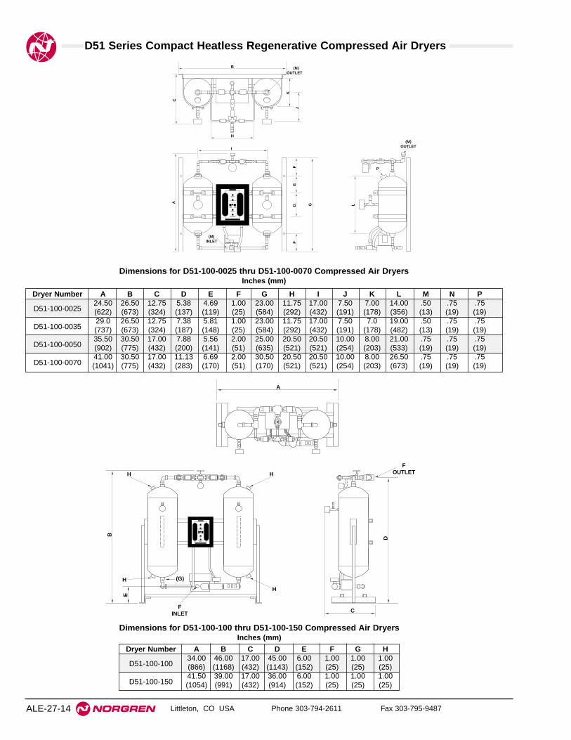
Dryer Number A B C D E F G H I J K L M N P
D51-100-002524.50 26.50 12.75 5.38 4.69 1.00 23.00 11.75 17.00 7.50 7.00 14.00 .50 .75 .75(622) (673) (324) (137) (119) (25) (584) (292) (432) (191) (178) (356) (13) (19) (19)
D51-100-003529.0 26.50 12.75 7.38 5.81 1.00 23.00 11.75 17.00 7.50 7.0 19.00 .50 .75 .75(737) (673) (324) (187) (148) (25) (584) (292) (432) (191) (178) (482) (13) (19) (19)
D51-100-005035.50 30.50 17.00 7.88 5.56 2.00 25.00 20.50 20.50 10.00 8.00 21.00 .75 .75 .75(902) (775) (432) (200) (141) (51) (635) (521) (521) (254) (203) (533) (19) (19) (19)
D51-100-007041.00 30.50 17.00 11.13 6.69 2.00 30.50 20.50 20.50 10.00 8.00 26.50 .75 .75 .75(1041) (775) (432) (283) (170) (51) (170) (521) (521) (254) (203) (673) (19) (19) (19)
Dimensions for D51-100-0025 thru D51-100-0070 Compressed Air DryersInches (mm)
K
J
C
B
H
A G
FF
E
LD
I
(M)INLET
P
(M)OUTLET
(N)OUTLET
A
B
D
H
FINLET
H H
H
C
E
(G)
FOUTLET
Dryer Number A B C D E F G H
D51-100-10034.00 46.00 17.00 45.00 6.00 1.00 1.00 1.00(866) (1168) (432) (1143) (152) (25) (25) (25)
D51-100-15041.50 39.00 17.00 36.00 6.00 1.00 1.00 1.00(1054) (991) (432) (914) (152) (25) (25) (25)
Dimensions for D51-100-100 thru D51-100-150 Compressed Air DryersInches (mm)

D51 Series Compact Heatless Regenerative Compressed Air Dryers
Littleton, CO USA Phone 303-794-2611 Fax 303-795-9487 ALE-27-15
Dryer Number A B C D E
D51-100-20065.00 34.00 35.00 61.00 1.50(1651) (1156) (889) (1549) (38)
D51-100-25079.00 34.00 35.00 75.00 1.50(2007) (1156) (889) (1905) (38)
D51-100-35065.00 38.00 35.00 62.00 1.50(1651) (965) (889) (1575) (38)
D51-100-50095.00 38.00 27.00 91.00 2.00(2413) (965) (686) (2311) (51)
D51-100-65094.00 42.00 29.00 90.00 2.00(2388) (1067) (7366) (2286) (51)
D
A
B C
24"
EINLET
EOUTLET
7-1/
2 "
Dimensions for D51-100-200 thru D51-100-650Compressed Air Dryers
Inches (mm)
14"
B
D
A C
FINLET
FOUTLET
Dryer Number A B C D E F
D51-100-0800 51.00 100.00 40.00 96.00 2.50 2.5(1295) (2540) (1016) (2438) (64) (64)
D51-100-1000 54.50 102.00 40.00 98.00 3.00 3.00(1384) (2591) (1016) (2489) (76) (76)
D51-100-1250 68.00 109.00 40.00 105.00 3.00 3.00(1727) (2769) (1016) (2667) (76) (76)
D51-100-1500 72.00 94.00 42.00 89.00 3.00 3.00(1829) (2388) (1067) (2261) (76) (76)
D51-100-2000 66.00 111.00 42.00 107.00 3.00 3.00(1676) (2819) (1067) (2718) (76) (76)
D51-100-2500 78.00 116.00 55.00 111.00 4.00 4.00(1981) (2946) (1397) (2819) (102) (102)
D51-100-3000 99.00 113.00 57.50 108.00 4.00 4.00(2515) (2870) (1461) (2743) (102) (102)
D51-100-3500 99.00 117.00 58.00 112.00 4.00 4.00(2515) (2972) (1473) (2845) (102) (102)
D51-100-4500 105.00 136.00 58.00 130.00 6.00 6.00(2667) (3454) (1473) (3302) (152) (152)
D51-100-5500 105.00 125.00 58.00 119.00 6.00 6.00(2667) (3175) (1473) (3023) (152) (152)
D51-100-6250 116.00 138.00 58.00 132.00 6.00 6.00(2946) (3505) (1473) (3353) (152) (152)
Dimensions for D51-100-0800 thru D51-100-6250 Compressed Air Dryers
Inches (mm)

Littleton, CO USA Phone 303-794-2611 Fax 303-795-9487
D60 Series Dryers
● Delivers -40°pressure dew point
● Provides continuous supply of dry air
● Operates automatically with flexible controls
● Reduces purge air requirements
D60 Series Externally HeatedRegenerative Compressed Air Dryers
SpecificationsMaximum Working Pressure: 150 psigMaximum Inlet Air Temperature: 110°FElectrical Requirements: 460v/60 hz 3ph (control circuit 115v/60 hz/1ph)Dry Vessel: ASME Code, Section VIII and latest addendaExterior Finish: Industrial enamelPurge Air Consumption for Regeneration: 7%
Standard EquipmentOn/Off switchDryer running lightPurge adjustment valvePurge cooling valvePurge control pressure gaugePurge control valvePurge exhaust mufflersTower pressure gaugesTower pressure relief valvesElectric heaterHeater high temperature controlCheck valvesPneumatically actuated switching valvesPilot control valvePilot control air filterPilot air switching valvesRegeneration valveASME Coded vesselsJacketed insulationActivated alumina desiccant (shipped separately)Desiccant fill and drain portsStainless steel air diffuser screensNEMA 1 enclosureProgrammable logic controller460-3-60 main power circuit115-1-60 control circuitStructural steel frame
ALE-27-16
Optional EquipmentAutomatic logic functionsPurge saving systemHigh humidity warning lightFail-to-switch warning lightPurge exhaust temperature controlAudible alarm(s)Tower indicating lightsNEMA 4 or 12 ratingVisual moisture indicatorPrefilter (recommended)Afterfilter (recommended)Dryer bypass systemSteam to air heat exchangerMolecular sieve and silica gel desiccants
Model Weight HeaterNumber lbs (kg) KW
D60-400-0100 700 (318) 1D60-400-0175 825 (374) 1-1/2D60-400-0250 900 (408) 2D60-400-0350 1,500 (680) 2-1/2D60-400-0500 2,400 (1,089) 4D60-400-0700 2,900 (1,315) 5D60-400-0850 3,350 (1,520) 6D60-400-1000 3,800 (1,724) 8D60-400-1350 5,000 (2,268) 10D60-400-1700 5,500 (2,495) 12D60-400-2100 7,200 (3,266) 15D60-400-2400 8,750 (3,969) 17D60-400-3100 11,000 (4,990) 25D60-400-3800 14,200 (6,441) 33D60-400-4300 16,300 (7,393) 33D60-400-5000 17,600 (7,983) 42D60-400-6250 20,200 (9,163) 50
Weights and Heater Specifications

D60 Series Externally Heated Regenerative Compressed Air Dryers
Littleton, CO USA Phone 303-794-2611 Fax 303-795-9487 ALE-27-17
Model 75 100 125 150Number* psig psig psig psig
D60-400-0100 78 100 122 144(37) (47) (57) (68)
D60-400-0175 137 175 213 252(64) (82) (100) (85)
D60-400-0250 196 250 304 359(92) (118) (143) (169)
D60-400-0350 274 350 426 503(129) (165) (200) (236)
D60-400-0500 391 500 609 718(184) (235) (286) (337)
D60-400-0700 547 700 853 1,005(257) (329) (401) (472)
D60-400-0850 665 850 1,035 1,220(313) (400) (486) (573)
D60-400-1000 782 1,000 1,218 1,436(368) (470) (572) (675)
D60-400-1350 1,056 1,350 1,644 1,938(496) (635) (773) (911)
D60-400-1700 1,329 1,700 2,071 2,441(625) (799) (973) (1147)
D60-400-2100 1,642 2,100 2,558 3,016(772) (987) (1202) (1418)
D60-400-2400 1,877 2,400 2,923 3,446(882) (1128) (1374) (1620)
D60-400-3100 2,424 3,100 3,776 4,451(1139) (1457) (1775) (2092)
D60-400-3800 2,972 3,800 4,628 5,456(1397) (1786) (2175) (2564)
D60-400-4300 3,363 4,300 5,237 6,175(1581) (2021) (2461) (2902)
D60-400-5000 3,910 5,000 6,090 7,180(1838) (2350) (2862) (3375)
D60-400-6250 4,888 6,250 7,612 8,975(2297) (2938) (3578) (4218)
Flow Capacity Selection Chart[scfm (dm3/s) @ 100°F (38°C) inlet temperature and
-40°F (-40°C) pressure dew point]
* For complete D60 product numbering system see ALE-27-26.
D
CB
A E
FOUTLET
FINLET
Dryer Number A B C D E F
D60-400-0100 36.00 77.50 68.00 6.00 34.00 1.00(914) (1969) (1727) (152) (864) (25)
D60-400-0175 40.00 82.00 72.00 7.00 38.00 1.50(1016) (2083) (1829) (178) (965) (38)
D60-400-0250 42.00 71.00 61.00 7.00 43.00 1.50(1067) (1803) (1549) (178) (1092) (38)
D60-400-0350 42.00 86.00 85.00 7.00 43.00 1.50(1067) (2184) (2159) (178) (1092) (38)
D60-400-0500 50.00 97.00 95.00 10.00 44.00 2.00(1270) (2464) (2413) (254) (1118) (51)
Dimensions for D60-400-0100 thru D60-400-0500 Externally HeatedRegenerative Compressed Air Dryers
inches (mm)
D12
B
A C
FOUTLET
EINLET NOTE: HEATER MAY
BE HORIZONTAL
Dryer Number A B C D E F
D60-400-700 44.00 109.00 48.00 105.00 2.00 2.00(1118) (2769) (1219) (2667) (51) (51)
D60-400-850 50.00 111.00 50.00 106.00 2.50 2.50(1270) (2819) (1270) (2692) (64) (64)
D60-400-1000 71.00 93.00 61.00 89.00 3.00 3.00(1803) (2362) (1549) (2261) (76) (76)
D60-400-1350 71.00 110.00 61.00 106.00 3.00 3.00(1803) (2794) (1549) (2692) (76) (76)
D60-400-1700 78.00 100.00 61.00 96.00 3.00 3.00(1981) (2540) (1549) (2438) (76) (76)
D60-400-2100 95.00 97.50 70.00 93.50 3.00 3.00(2413) (2477) (1778) (2375) (76) (76)
D60-400-2400 99.00 114.00 67.00 109.00 4.00 4.00(2515) (2896) (1702) (2769) (102) (102)
D60-400-3100 105.00 112.00 67.00 107.00 4.00 4.00(2667) (2845) (1702) (2718) (102) (102)
D60-400-3800 105.00 120.00 67.00 115.00 4.00 4.00(2667) (3048) (1702) (2921) (102) (102)
D60-400-4300 116.00 120.00 85.00 114.00 6.00 6.00(2946) (3048) (2159) (2896) (152) (152)
D60-400-5000 116.00 127.00 85.00 121.00 6.00 6.00(2946) (3226) (2159) (3073) (152) (152)
D60-400-5500 122.00 113.00 85.00 107.00 6.00 6.00(3099) (2870) (2159) (2718) (152) (152)
D60-400-6250 122.00 121.00 85.00 115.00 6.00 6.00(3099) (3073) (2159) (2921) (152) (152)
Dimensions for D60-400-0700 thru D60-400-6250 Externally HeatedRegenerative Compressed Air Dryers
inches (mm)

Littleton, CO USA Phone 303-794-2611 Fax 303-795-9487
D70 Series Dryers
● Delivers -40°pressure dew point
● Provides continuous supply of dry air
● Operates automatically with flexible controls
● Reduces purge air requirements
D70 Series Blower PurgeRegenerative Compressed Air Dryers
SpecificationsMaximum Working Pressure: 150 psigMaximum Inlet Air Temperature: 110°FElectrical Requirements: 460v/60 hz 3ph (control circuit 115v/60 hz/1ph)Dry Vessel: ASME Code, Section VIII and latest addendaExterior Finish: Industrial enamelPurge Air Consumption for Regeneration: Less than 5%Standard EquipmentOn/Off switchDryer running lightPurge adjustment valvePurge cooling valvePurge control pressure gaugePurge control valvePurge exhaust mufflersTower pressure gaugesTower pressure relief valvesBlowerBlower intake filterElectric heaterHeater high temperature controlCheck valvesPneumatically actuated switching valvesPilot control valvePilot control air filterPilot air switching valvesRegeneration valveASME Coded vesselsJacketed insulationActivated alumina desiccant (shipped separately)Desiccant fill and drain portsStainless steel air diffuser screensNEMA 1 enclosureProgrammable logic controller460-3-60 main power circuit115-1-60 control circuitStructural steel frame
ALE-27-18
Optional EquipmentAutomatic logic functionsPurge saving systemHigh humidity warning lightFail-to-switch warning lightPurge exhaust temperature controlAudible alarm(s)Tower indicating lightsNEMA 4 or 12 ratingVisual moisture indicatorPrefilter (recommended)Afterfilter (recommended)Dryer bypass systemSteam to air heat exchangerMolecular sieve and silica gel desiccants
Model Weight Blower HeaterNumber lbs. (kg) HP KW
D70-400-0250 1,200 (544) 3 4D70-400-0350 1,500 (680) 3 5D70-400-0500 2,400 (1,089) 5 8D70-400-0700 2,900 (1,315) 5 10D70-400-1000 3,800 (1,724) 10 12D70-400-1350 5,000 (2,268) 10 17D70-400-1700 5,500 (5,495) 15 25D70-400-2400 8,750 (3,969) 15 33D70-400-3100 11,000 (4,990) 15 42D70-400-3800 14,200 (6,441) 20 50D70-400-4300 16,300 (7,394) 20 58D70-400-5000 17,700 (8,029) 25 67D70-400-6250 20,200 (9,163) 30 87
Weights and Heater Specifications

D70 Series Blower Purged Regenerative Compressed Air Dryers
Littleton, CO USA Phone 303-794-2611 Fax 303-795-9487 ALE-27-19
Model 75 100 125 150Number* psig psig psig psig
D70-400-0250 196 250 304 359(92) (118) (143) (169)
D70-400-0350 274 350 426 503(129) (165) (200) (236)
D70-400-0500 391 500 609 718(184) (235) (286) (337)
D70-400-0700 547 700 853 1,005(257) (329) (401) (472)
D70-400-0850 665 850 1035 1220(313) (400) (487) (574)
D70-400-1000 782 1,000 1,218 1,436(368) (470) (572) (675)
D70-400-1350 1,056 1,350 1,644 1,938(496) (635) (773) (911)
D70-400-1700 1,329 1,700 2,071 2,441(625) (799) (973) (1147)
D70-400-2100 1642 2100 2558 3016(773) (988) (1204) (1419)
D70-400-2400 1,877 2,400 2,923 3,446(882) (1128) (1374) (1620)
D70-400-3100 2,424 3,100 3,776 4,451(1139) (1457) (1775) (2092)
D70-400-3800 2,972 3,800 4,628 5,456(1397) (1786) (2175) (2564)
D70-400-4300 3,363 4,300 5,237 6,175(1581) (2021) (2461) (2902)
D70-400-5000 3,910 5,000 6,090 7,180(1838) (2350) (2862) (3375)
D70-400-6250 4,888 6,250 7,612 8,975(2297) (2938) (3578) (4218)
Flow Capacity Selection Chart[scfm (dm3/s) @ 100°F (38°C) inlet temperature, and
-40°F (-40°C) pressure dew point]
* For complete D70 product numbering system see ALE-27-27.
D
12
B
A C
OUTLETBB
INLETAA
Dryer Number A B C D E F
D70-400-0100 64 78 45 68 1 1(1626) (1981) (1143) (1727) (25) (25)
D70-400-0175 68 82 50 72 1.5 1.5(1727) (2083) (1270) (1829) (38) (38)
D70-400-0250 72 71 55 61 1.5 1.5(1829) (1803) (1397) (1549) (38) (38)
D70-400-0350 72 89 55 79 1.5 1.5(1829) (2261) (1397) (2007) (38) (38)
D70-400-0500 78 101 60 90 2 2(1981) (2565) (1524) (2286) (51) (51)
Dimensions for D70-400-0100 thru D70-400-0500 Blower PurgeRegenerative Compressed Air Dryers
inches (mm)
D12
B
A C
FOUTLET
EINLET NOTE: HEATER MAY
BE HORIZONTAL
Dryer Number A B C D E F G
D70-400-0700 49 101 62 99 49 2 2(1245) (2565) (1575) (2515) (1245) (51) (51)
D70-400-0850 50 111 67 106 50 2.5 2.5(1270) (2819) (1702) (2692) (1270) (64) (64)
D70-400-1000 72 99 70 95 72 3 3(1829) (2515) (1778) (2413) (1829) (76) (76)
D70-400-135072 116 70 112 72 3 3
(1829) (2946) (1778) (2845) (1829) (76) (76)
D70-400-170074 100 75 96 78 3 3
(1880) (2540) (1905) (2438) (1981) (76) (76)
D70-400-210079 98 95 94 91 3 3
(2007) (2489) (2413) (2388) (2311) (76) (76)
D70-400-240088 114 95 109 99 4 4
(2235) (2896) (2413) (2769) (2515) (102) (102)
D70-400-310093 112 95 107 105 4 4
(2362) (2845) (2413) (2718) (2667) (102) (102)
D70-400-380093 120 95 115 105 4 4
(2362) (3048) (2413) (2921) (2667) (102) (102)
D70-400-4300100 120 100 114 116 6 6
(2540) (3048) (2540) (2896) (2946) (152) (152)
D70-400-5000100 127 100 121 116 6 6
(2540) (3226) (2540) (3073) (2946) (152) (152)
D70-400-5500105 113 107 107 122 6 6
(2667) (2870) (2718) (2718) (3099) (152) (152)
D70-400-6250105 121 107 115 122 6 6
(2667) (3073) (2718) (2921) (3099) (152) (152)
Dimensions for D70-400-0700 thru D70-400-6250 Blower PurgeRegenerative Compressed Air Dryers
inches (mm)

Littleton, CO USA Phone 303-794-2611 Fax 303-795-9487
W74D
● Excelon Quikclamp™ design provides in-line ormodular installation with 72, 73 and 74 Seriesproducts.
● Helps eliminate condensate at point-of-use.
● Replaceable element filters outlet air to help preventdesiccant dust migration down stream.
● Desiccant color changes from blue to pink whendesiccant replacement is needed.
● Transparent or metal bowl available. On models withmetal bowl, moisture indicator on top of bodyindicates condition of desiccant.
● Desiccant can be dried and reused or replaced withnew packet.
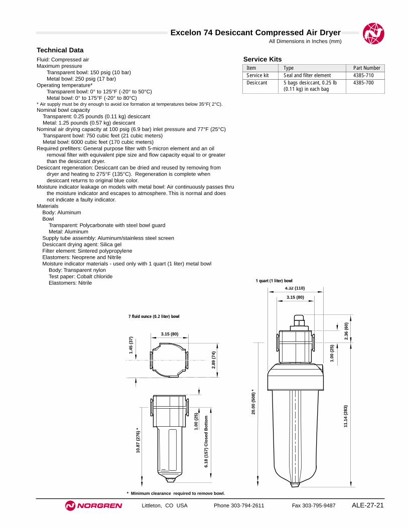
● Typical dew point supression of 15°F (-10°C) belowinlet ambient pressure dew point.
Excelon 74 Desiccant Compressed Air Dryer1/4", 3/8", and 1/2" Port Sizes
ALE-27-20
Ordering Information. Models listed include PTF threads and a closed bottom bowl.
Port Size Bowl Model Weight lb (kg)3/8" Transparent, 7 fluid ounce (0.2 liter) W74D-3AN-NPN 2.00 (0.91)1/2" Transparent, 7 fluid ounce (0.2 liter) W74D-4AN-NPN 2.00 (0.91)1/2" Metal, 1 quart (1 liter) W74D-4AN-NMN 4.25 (1.93)
Alternative Models
W 7 4 -D ★ ★ - ★★ ★ ★
Threads SubstitutePTF AISO Rc taper BISO G parallel G
Drain SubstituteClosed bottom (no drain) N
Flow SubstituteNot applicable N
Port Size Substitute1/4" 23/8" 31/2" 4
Bowl Substitute1 quart (1 liter) metal M7 fluid ounce (0.2 liter) Ptransparent with guard
Moisture Indicator * SubstituteNo indicator NWith indicator D
* Moisture indicator used only with dryers equipped with metal bowl.
ISO Symbols
Excelon 74 Desiccant Compressed Air Dryer
Littleton, CO USA Phone 303-794-2611 Fax 303-795-9487 ALE-27-21
All Dimensions in Inches (mm)
Technical DataFluid: Compressed airMaximum pressure
Transparent bowl: 150 psig (10 bar)Metal bowl: 250 psig (17 bar)
Operating temperature*Transparent bowl: 0° to 125°F (-20° to 50°C)Metal bowl: 0° to 175°F (-20° to 80°C)
* Air supply must be dry enough to avoid ice formation at temperatures below 35°F( 2°C).Nominal bowl capacity
Transparent: 0.25 pounds (0.11 kg) desiccantMetal: 1.25 pounds (0.57 kg) desiccant
Nominal air drying capacity at 100 psig (6.9 bar) inlet pressure and 77°F (25°C)Transparent bowl: 750 cubic feet (21 cubic meters)Metal bowl: 6000 cubic feet (170 cubic meters)
Required prefilters: General purpose filter with 5-micron element and an oilremoval filter with equivalent pipe size and flow capacity equal to or greaterthan the desiccant dryer.
Desiccant regeneration: Desiccant can be dried and reused by removing fromdryer and heating to 275°F (135°C). Regeneration is complete whendesiccant returns to original blue color.
Moisture indicator leakage on models with metal bowl: Air continuously passes thruthe moisture indicator and escapes to atmosphere. This is normal and doesnot indicate a faulty indicator.
MaterialsBody: AluminumBowl
Transparent: Polycarbonate with steel bowl guardMetal: Aluminum
Supply tube assembly: Aluminum/stainless steel screenDesiccant drying agent: Silica gelFilter element: Sintered polypropyleneElastomers: Neoprene and NitrileMoisture indicator materials - used only with 1 quart (1 liter) metal bowl
Body: Transparent nylonTest paper: Cobalt chlorideElastomers: Nitrile
Service KitsItem Type Part NumberService kit Seal and filter element 4385-710Desiccant 5 bags desiccant, 0.25 lb 4385-700
(0.11 kg) in each bag
4.32 (110)
3.15 (80)
11.1
4 (2
83)
1.00
(25
)
2.36
(60
)
20.0
0 (5
08)
*
2.89
(74
)
1.00
(25
)
1.45
(37
) 3.15 (80)
6.18
(15
7) C
lose
d B
ott
om
10.8
7 (2
76)
*
* Minimum clearance required to remove bowl.
7 fluid ounce (0.2 liter) bowl
1 quart (1 liter) bowl

Littleton, CO USA Phone 303-794-2611 Fax 303-795-9487
F21 / F61
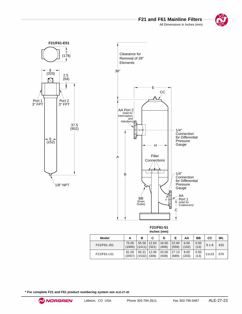
● High flow mainline system filters
● The F21 provides 1 micron particle removal filtration
● The F61 provides 0.01 oil coalescing
● The F61 features carbon type vapor removal filtration
● Optional automatic or timer drains available
F21and F61 Mainline Filters
Technical DataMaximum Working Pressure: 150 psig (10 bar)Maximum Inlet Temperature: 150°F (65°C)Dryer Vessel: ASME Code, Section VIII, and latest addenda (4" and
larger units)Exterior Finish: Industrial enamelStandard: Manual drain valve, and pressure differential gauge.
ALE-27-22
Model A B C D E F G H J AA BB CC DD Wt.
F21/F61-F0145.13 17.63 36.50 3.50 4.50 6.00 5.50 8.63 41.00 3.00 0.50 0.25 3.00
175(1146) (448) (927) (89) (114) (152) (140) (219) (1041) (76) (13) (6) (76)
F21/F61-G0144.38 21.75 34.88 4.00 4.50 6.38 5.50 12.75 37.00 4.00 0.50 0.25 4.00
300(1127) (552) (886) (102) (114) (162) (140) (324) (940) (102) (13) (6) (102)
F21/F61-J0156.25 23.75 45.75 5.00 5.50 6.50 7.00 12.75 51.00 6.00 0.50 0.25 4.00
350(1429) (603) (1162) (127) (140) (165) (178) (324) (1295) (152) (13) (6) (102)
F21/F61-01Inches (mm)
C
H
BB Drain Port
J
D
B
5/16" Plate
CC CC AA
AA
A FilterCoupling
E EF G
DD
FilterCoupling
DD
F21 and F61 Mainline Filters
Littleton, CO USA Phone 303-794-2611 Fax 303-795-9487 ALE-27-23
All Dimensions in Inches (mm)
* For complete F21 and F61 product numbering system see ALE-27-30
Model A B C D E AA BB CC Wt.
F21/F61-J5175.00 55.56 12.63 16.00 22.00 6.00 0.50
6 x 8 415(1905) (1411) (321) (406) (559) (152) (13)
F21/F61-L5181.00 60.31 12.06 20.00 27.13 8.00 0.50
11x15 670(2057) (1532) (306) (508) (689) (203) (13)
F21/F61-51Inches (mm)
8 (203)
6 (152)
37.5(952)
7 (178)
2.5 (64)
1/8" NPT
Port 23" FPT
Port 13" FPT
ECC
AAPort 1(Inlet for Coalescers)
1/4" Connection for Differential Pressure Gauge
1/4" Connection for Differential Pressure Gauge
A
B
C
36"
AA Port 2(Inlet for
Interceptors and
Adsobers)
Clearance for Removal of 28" Elements
BB(DrainOutlet)
H
Filter Connections
F21/F61-E01

D11 Series Product Numbering System
Littleton, CO USA Phone 303-794-2611 Fax 303-795-9487ALE-27-24
Unit
Series
Voltage
Accessory Package
Cabinet Options
D = Compressed Air Dryer
11 Series = Refrigerated, R134a
1 = 115-60 Hz-1/110-50 Hz-1 (5 thru 150 scfm units)2 = 230/220-60 Hz-1/200-50 Hz-1 (5 & 10, 40 thru 200 scfm units)3 = 230/208-60 Hz-3 (200 scfm only)4 = 460-60 Hz-3 (200 scfm only)6 = 240/220-50 Hz-1 (5 thru 200 scfm units)
0 = (5 thru 100 scfm units)16'' power cord
(130 thru 200 scfm units)On/Off switch, power on and high temperature indicator lights, drain tube, panelmounted refrigerant suction pressure gauge, and electrical terminal block
1 = (5 thru 20 scfm units)Panel mounted refrigerant suction pressure gauge, drain tube kit and 16'' powercord
2 = (5 thru 100 scfm units)Panel mounted refrigerant suction pressure gauge, 6’ power cord, on/off switch,power on and high temperature indicator lights and drain tube kit
3 = (30 thru 100 scfm units)Panel mounted refrigerant suction pressure gauge, 6’ power cord, on/off switch,power on and high temperature indicator lights, outlet air pressure gauge, inlet airtemperature gauge, and drain tube kit
(130 thru 200 scfm units)Panel mounted refrigerant suction pressure gauge, electrical terminal block, on/offswitch, power on and high temperature indicator lights, outlet air pressure gauge,inlet air temperature gauge and drain tube kit
4 = (130 thru 200 scfm units)Panel mounted refrigerant suction pressure gauge, refrigerant discharge pressuregauge, electrical terminal block, on/off switch, power on and high temperatureindicator lights, outlet air pressure gauge, inlet air temperature gauge, outlet airtemperature gauge, inlet air pressure gauge and drain tube kit
Position
Sample Model Number
1
2 3
4
5
60 = No side panels1 = Side panels2 = Ambient filter with no side panels3 = Ambient filter with side panels
0005 = 5 scfm0010 = 10 scfm0015 = 15 scfm0020 = 20 scfm0030 = 30 scfm0040 = 40 scfm0050 = 50 scfm0075 = 75 scfm0100 = 100 scfm0130 = 130 scfm0150 = 150 scfm0200 = 200 scfm
7 8 Size9 10
D 1 1 - 1 0 0 - 0 0 1 0
1 2 3 - 4 5 6 - 7 8 9 10

D10 Series Product Numbering System
Littleton, CO USA Phone 303-794-2611 Fax 303-795-9487 ALE-27-25
Unit
Series
Voltage
Accessory Package
Options
D = Compressed Air Dryer
10 Series = Refrigerated, R22
2 = 230/208-60 Hz-13 = 230/208-60 Hz-34 = 460-60 Hz-35 = 600/550-60 Hz-36 = 240/220-50 Hz-17 = 240/220-50 Hz-38 = 420/380-50 Hz-3
0 = (250 thru 500 scfm units)On/Off switch (control circuit), power on light, refrigerant suction pressure gauge,air inlet temperature gauge and air outlet pressure gauge
(600 scfm and larger units)On/off switch (control circuit), power on light, refrigerant suction pressure gauge,refrigerant discharge pressure gauge, air inlet and outlet temperature gauges, andair inlet and outlet pressure gauges
1 = (250 thru 500 scfm units)On/off switch (control circuit),power on light, refrigerant suction pressure gauge,refrigerant discharge pressure gauge, air inlet and outlet pressure gauges, and airinlet and outlet temperature gauges
2 = On/off switch (control circuit),power on light, refrigerant suction pressure gauge,refrigerant discharge pressure gauge, air inlet and outlet pressure gauges, air inletand outlet temperature gauges, and alarm bell
3 = On/off switch (control circuit),power on light, refrigerant suction pressure gauge,refrigerant discharge pressure gauge, air inlet and outlet pressure gauges, and airinlet and outlet temperature gauges,and flow meter
4 = On/off switch (control circuit),power on light, refrigerant suction pressure gauge,refrigerant discharge pressure gauge, air inlet and outlet pressure gauges, air inletand outlet temperature gauges, alarm bell and flow meter
Position
Sample Model Number
1
2 3
4
5
60 = Air-cooled1 = Water-cooled2 = Air-cooled with ambient filters
0250 = 250 scfm0325 = 325 scfm0400 = 400 scfm0500 = 500 scfm0600 = 600 scfm0800 = 800 scfm1000 = 1000 scfm1250 = 1250 scfm1500 = 1500 scfm*1750 = 1750 scfm2000 = 2000 scfm2500 = 2500 scfm3200 = 3200 scfm4000 = 4000 scfm5000 = 5000 scfm6250 = 6250 scfm7500 = 7500 scfm
7 8 Size9 10
D 1 0 - 2 0 0 - 0 2 5 0
1 2 3 - 4 5 6 - 7 8 9 10
* Not available as a water-cooled unit

D50 Series Product Numbering System
Littleton, CO USA Phone 303-794-2611 Fax 303-795-9487ALE-27-26
Unit
Series
Voltage
Model
Options
D = Compressed Air Dryer
50 Series = Compact Heatless Regenerative
1 = 115-60 Hz2 = 230-60 Hz6 = 240/220-50 Hz-1A = 12VDCB = 24VDC
0 = Standard Model5 = Economy Model
Position
Sample Model Number
1
2 3
4
5
61 = -66°F Dew point (standard unit only)4 = Hazardous location, -40°F Dew point (standard unit only)5 = Hazardous location, -66°F Dew point (standard unit only)
0010 = 10 scfm0025 = 25 scfm0050 = 50 scfm
7 8 Size9 10
D 5 0 - 1 0 0 - 0 0 5 0
1 2 3 - 4 5 6 - 7 8 9 10

D51 Series Product Numbering System
Littleton, CO USA Phone 303-794-2611 Fax 303-795-9487 ALE-27-27
Unit
Series
Voltage
Model
Options
D = Compressed Air Dryer
51 Series = Heatless Regenerative
1 = 115-60 Hz-1
0 = Instrumentation Model
Position
Sample Model Number
1
2 3
4
5
6
0 = No options1 = Visual moisture indicator2 = Fail-to-switch warning light3 = Purge saving system4 = Purge saving system and fail to switch warning light5 = Purge saving system with high humidity warning light6 = Purge saving system with high humidity warning light,
fail-to-switch warning light7 = Visual moisture indicator and fail-to-switch warning light8 = Purge saving system with high humidity warning light,
visual moisture indicator, and fail-to-switch warning light
7 8 Size9 10
D 5 1 - 1 0 0 - 0 0 5 0
1 2 3 - 4 5 6 - 7 8 9 10
0025 = 25 scfm0035 = 35 scfm0050 = 50 scfm0070 = 70 scfm0100 = 100 scfm0150 = 150 scfm0200 = 200 scfm0250 = 250 scfm0350 = 350 scfm0500 = 500 scfm0650 = 650 scfm0800 = 800 scfm1000 = 1,000 scfm1250 = 1,250 scfm1500 = 1,500 scfm2000 = 2,000 scfm2500 = 2,500 sfcm3000 = 3,000 scfm3500 = 3,500 scfm4500 = 4,500 scfm5500 = 5,500 scfm6250 - 6,250 scfm

D60 Series Product Numbering System
Littleton, CO USA Phone 303-794-2611 Fax 303-795-9487ALE-27-28
Unit
Series
Voltage
Model
Options
D = Compressed Air Dryer
60 Series = Externally Heated Regenerative
4 = 460-60 Hz-3/(control circuit 115-60 Hz-1)
0 = Standard Model
Position
Sample Model Number
1
2 3
4
5
6
0 = No options1 = Visual moisture indicator2 = Fail-to-switch warning light3 = Purge saving system4 = Purge saving system and fail to switch warning light
7 8 Size9 10
D 6 0 - 4 0 0 - 1 0 0 0
1 2 3 - 4 5 6 - 7 8 9 10
0100 = 100 scfm0175 = 175 scfm0250 = 250 scfm0350 = 350 scfm0500 = 500 scfm0700 = 700 scfm0850 = 850 scfm1000 = 1,000 scfm1350 = 1,350 scfm1700 = 1,700 scfm2100 = 2,100 scfm2400 = 2,400 sfcm3100 = 3,100 scfm3800 = 3,800 scfm4300 = 4,300 scfm5000 = 5,000 scfm6250 - 6,250 scfm
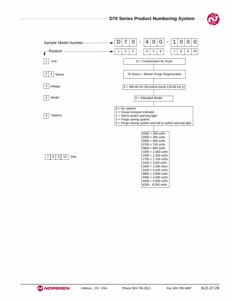
D70 Series Product Numbering System
Littleton, CO USA Phone 303-794-2611 Fax 303-795-9487 ALE-27-29
Unit
Series
Voltage
Model
Options
D = Compressed Air Dryer
70 Series = Blower Purge Regenerative
4 = 460-60 Hz-3/(control circuit 115-60 Hz-1)
0 = Standard Model
Position
Sample Model Number
1
2 3
4
5
6
0 = No options1 = Visual moisture indicator2 = Fail-to-switch warning light3 = Purge saving system4 = Purge saving system and fail to switch warning light
7 8 Size9 10
D 7 0 - 4 0 0 - 1 0 0 0
1 2 3 - 4 5 6 - 7 8 9 10
0250 = 250 scfm0350 = 350 scfm0500 = 500 scfm0700 = 700 scfm0850 = 850 scfm1000 = 1,000 scfm1350 = 1,350 scfm1700 = 1,700 scfm2100 = 2100 scfm2400 = 2,400 sfcm3100 = 3,100 scfm3800 = 3,800 scfm4300 = 4,300 scfm5000 = 5,000 scfm6250 - 6,250 scfm
Littleton, CO USA Phone 303-794-2611 Fax 303-795-9487ALE-27-30
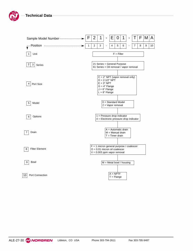
Technical Data
Unit
Series
Port Size
Model
Options
F = Filter
21 Series = General Purpose61 Series = Oil removal / vapor removal
C = 2" NPT (vapor removal only)D = 2-1/2" NPTE = 3" NPTG = 4" FlangeJ = 6" FlangeL = 8" Flange
0 = Standard Model2 = Vapor removal
Position
Sample Model Number
1
2 3
4
5
6
Drain7
1 = Pressure drop indicator4 = Electronic pressure drop indicator
F 2 1 - E 0 1 - T F M A
1 2 3 - 4 5 6 - 7 8 9 10
A = Automatic drainM = Manual drainT = Timer drain
Filter Element8F = 1 micron general purpose / coalescerO = 0.01 micron oil coalescerV = 0.003 ppm vapor removal
Bowl9 M = Metal bowl / housing
Port Connection10 A = NPTFT = Flange

Dryer Technical Data
Littleton, CO USA Phone 303-794-2611 Fax 303-795-9487 ALE-27-31
Selecting an Air Dryer
Identify the following operational conditions:
1. Air flow requirement of your system in scfm:
● For dryers servicing a complete air system, multiply the compressor horsepower byfour to obtain an approximation of the compressor flow capacity in scfm.
● For dryers servicing a branch line, determine the maximum flow for that branch.
2. Dryer inlet air pressure in psig:
● Best results are obtained with a high inlet air pressure. Do not exceed the maximuminlet air pressure listed under Specifications.
3. Dryer inlet air temperature in °F:
● Bests results are obtained with a low inlet air temperature. Do not exceed maximumtemperature listed under Specifications.
4. Ambient air temperature at dryer in °F:
● Ambient temperature must be within the range listed under Specifications.
5. Minimum temperature to which downstream piping will be exposed in °F:Pressure dewpoint required in °F:
● The lowest downstream temperature determines dewpoint requirement. A 35°Fpressure dewpoint is the lowest practical dewpoint for refrigerant dryers. In somecases a 50°F pressure dewpoint may be acceptable, resulting in greater flowcapacity and cost savings. The dewpoint chosen should be approximately 10°F (6°C)below the lowest downstream temperature.
6. Power requirements: Volts Cycle Phase
7. Air or water-cooled model:
● Use water-cooled model (available in 400 scfm size and larger) when ambienttemperature is above 110°F (43°C).
If your dryer operational conditions for Items 2, 3, and 4 are the same as the number in theshaded box* on the same line you need only determine which nominal capacity will meet yourpressure dewpoint requirement, Item 5. See Flow Specifications on facing page.
Operational conditions other than Standard Operating Conditions*, require use of the DryerSizing Formula to determine the appropriate dryer size for the application.
*Standard Operating Conditions, per ANSI/B93.45M, are used to obtain the nominal flow ratingfor Norgren dryers. These conditions are fully detailed under Flow Specifications on thefacing page.
Dryer Sizing
If conditions are other than standard operating conditions*, use thefollowing formula to determine dryer air flow rating (QR) required
for your system. ( QR = scfm)
QR = QA(K1)(K2)
Where:QR = Air flow rating required for dryer
QA = Actual flow requirement – Item 1
K1 = Correction factor for inlet temperature and operatingpressure (Chart 1)
K2 = Correction factor for ambient temperature (Chart 2)
Example
Given the following conditions, determine the dryer air flow ratingrequired.
1. Air flow requirement of system: 120 scfm2. Dryer inlet air pressure: 150 psig3. Dryer inlet air temperature: 80°F4. Ambient air temperature at dryer: 110°F5. Minimum downstream temperature: 50°F6. Power requirements: 115V, 60 cycle, 1 phase7. Air or water cooled: Air
SolutionQR = QA (K1)(K2)
QR = 120 scfm x .62 (Chart 1) x 1.11 (Chart 2)
QR = 82.6 scfm
A 100 scfm D11 dryer will fit this application.
100 psig*
100 psig*
QA = Q [ PA ]14.7 psia
QA = 23 cfm [139.4 psia] QA = 218.10 scfm or 218 scfm14.7 psia
∆P ≈ [ QR ]2
x 114.7 psia x ∆PsQS P
Where:∆P = Calculated pressure dropQR = Actual flowQS = Air flow at 35°F pressure dew point ratingP = Actual supply pressure in psia∆PS = Pressure drop at rated conditions and flow
Finding Pressure Drops for Non-standard FlowsUse the following formula to find the approximate pressure drop for flows notlisted in the flow specifications table
Chart 2 Ambient Correction Factor For 35°F (2°C) Pressure Dewpoint
Ambient Temperature Correction Factor K260°F 0.6670°F 0.7380°F 0.8190°F 0.90100°F 1.00110°F 1.11
Chart 1. Inlet Temperature F° vs. Inlet PressureCorrection Factor
60° 80° 100° 120° 130°Pressure psig Correction Factors K1
50 0.43 0.77 1.20 1.80 2.2375 0.39 0.70 1.07 1.56 1.89100 0.37 0.66 1.00 1.43 1.71125 0.36 0.63 0.95 1.34 1.60150 0.35 0.62 0.92 1.28 1.51175 0.35 0.60 0.90 1.24 1.46200 0.34 0.60 0.88 1.21 1.41
Atmospheric Pressure at Selected AltitudesAlt. above sea level ft Atmospheric Pressure (psi)
0 14.7500 14.4
1500 14.22000 13.92500 13.43000 13.13500 12.94000 12.74500 12.55000 12.2
Converting cfm at stated Pressure to scfmQ = Air flow in CFM at stated P pressureP - Pressure in psigPA = P pressure converted to pressure in psiaQA = Flow in scfm
Example:
Flow = 23 cfm at 125 psig (at 500' above sea level)PA = 125 psig /14.4** = 139.4
**See correction table at right for atmospheric pressure for your elevation
100 psig*