comprehensive study of venus by means of a low-cost …
TRANSCRIPT

X-625-70-203
COMPREHENSIVE STUDY OF VENUS BY MEANS OF A LOW-COST ENTRY-PROBE
AND ORBITER MISSION-SERIES
J EAINSWORTH
JUNE
4v1974
-JGODDARD SPACE CENTER GODDAR SPACEFLIGHT CNE
GREENBELT MARYLAND
-N711680-)7 00 (ACCESSION NUM-BER) (JRU)
) NATIO E VICE AES (
(N SA CROR TMX OR AD NUMBER) (CATEGORY)
X-625-70-203
COMPREHENSIVE STUDY OF VENUS
BY MEANS OF A LOW-COST ENTRY-PROBE
AND ORBITER MISSION-SERIES
J E Ainsworth
June 1970
GODDARD SPACE FLIGHT CENTER Greenbelt Maryland
ACKNOWLEDGMENTS
Many people have contributed to the material presented here
The Planetary Explorer bus vehicle and the Fields Particles and Aeronomy Orbiter mission were developed at GSFC under the dishyrection of P G Marcotte
The use of the Delta rocket and Planetary Explorer bus for a multishyprobe meteorological mission to Venus was first suggested and studied by C C Stephanides at GSFC and additional study under his direction was carried out under contract with the AVCO Corporation
The Mapping Orbiter has resulted in large part from the orbiter radar study done by H J Goldman and D L Roberts at IITRI
The Balloon Seismic Lander and Television Lander missions were developed as a company sponsored effort directed by S J Ducsai of the Martin Marietta Corporation
I wish to express my personal appreciation to the many scientists and engineers at GSFC and throughout -the country whose interest and assistance have sustained the effort of the past three years
iii
TABLE OF CONTENTS
Page
PART I-DOCUMENT OBJECTIVES
1 BACKGROUND 1
2 MISSION DEVELOPMENT 1
3 OBJECTIVES 2
PART II-MISSION-SERIES DESCRIPTION
1 LAUNCHING 5
11 Launch Vehicle 5 12 Launch Vehicle Capability 7
2 EARTH-VENUS TRANSIT AND VENUS ORBITING 9
21 Planetary Explorer Bus Vehicle 9 22 Transit Description 9 23 Bus Subsystems Description 11 24 Venus Orbit Description 16 25 Orbiting Bus Subsystems Description 18 26 Bus Development Status 23
3 AERONOMY AND METEOROLOGY PROBE MISSION 25
31 Mission Summary 25 32 The Bus 25 33 Three Small Probes 28 34 The Large Probe 36 35 Mission Status 44
4 FIELDS PARTICLES AND AERONOMY ORBITER MISSION 47
41 Mission Summary 47 42 Measurement 48 43 Mission Variations 48 44 Mission Status 49
~AcNOT
V
Page
PART U-MISSION-SERIES DESCRIPTION (Continued)
5 ATMOSPHERIC CIRCULATION (BALLOON) MISSION 51
51 Mission Summary 51 52 System Description 52 53 Alternate Mission Configurations 57 54 Mission Status w 57
6 MAPPING ORBITER MISSION 59
6i Mission Summary 59 62 Orbit Selection 62 63 Mapping Instruments 62 64 Storage Communication and Coverage 67 65 Mission Status 68
7 VENUS INTERIOR EXAMINATION (SEISMIC LANDER) MISSION 71
71 Mission Summary 71 72 Targeting 7373 73 The Bomb 73 74 Seismometer Lander 74 75 Communication 80 76 Discussion 080 77 Mission Status 81
8 VENUS SURFACE-INSPECTION (TELEVISION LANDER) MISSION 83
81 Mission Summary 83 82 Communication 87 83 Lander Instruments 88 84 Mission Status 93
PART rn-DISCUSSION
1 MISSION-SERIES OPTIMIZATION RELIABILITY LOW COST 95
2 INSTRUMENT STATUS 95
3 SYSTEM STATUS 96
4 MISSION-SERIES RATIONALE 96
vi
Page
REFERENCES 98
APPENDIX A 99
APPENDIX B 103
vii
PART I
DOCUMENT OBJECTIVES
1 BACKGROUND
Recent technical accomplishments and studies presage the beginning of a period of greatly increased interest in the exploration of Venus Three years ago Venus orbiters were known to be feasible but there was concern that descent-probes would not outlive atmospheric entry If descentshyprobes could indeed survive entry it seemed apparent that the high atshymospheric pressure and temperature near the surface and the rapid descent required to accomplish relay communication via a fly-by bus would limit probe use to pressure temperature and simple optical measurements A year later it was clear that not only was it possible to survive atmospheric entry but that a number of sophisticated atmospheric and cloud physics exshyperiments could be performed during slow descent to the Venus surface Still later less thali a year ago it became apparent that relatively simple vehicles could be designed which would allow useful measurement on the Venus surface by seismic and other instruments At about this same time Earth based microwave interferometer measurements of the polar temshyperature and the USSR Venus 5 and 6 measurements determined that both polar and mountain top temperatures were too hot to allow Earth forms of life to survive on the Venus surface The result of these findings is a reduction in the effort needed to meet international sterilization requirements
In less than three years we have advanced from a condition where poor prospects existed for making the in situ measurements necessary for a significant advance in our understanding of Venus to a condition where it is possible to apply a substantial number of the most efficient techniques and instruments used in four major areas of planet research aeronomy meteorology planet surface examination and planet-interior study In some instances the fabrication and use of the instruments for Venus will present less difficulty than is involved in their use on missions to Mars and other planets In other instances the special requirements of Venus use will stimulate the additional instrument development contemplated for improved Earth use
2 MISSION DEVELOPMENT
Present and past Venus mission studies have involved
a Delta launched payloads of 800 pounds
1
b Atlas-Centaur launched payloads of 1850 pounds
c Titan launched payloads of 3900 pounds
This document will consider the spectrum of uses of the 800 lb Delta payload
The first phase of the study of Delta payload uses is an attempt to select one of each of the different classes of missions necessary for a compreshyhensive study of Venus and to show both the feasibility of each class and the scope of its resulting Venus examination The classes of missions included in this first phase of the study are
a Aeronomy and meteorology using an entry bus and deicent probes
b Orbiter use for field particle and aeronomy measurements
c Atmospheric circulation measurement by means of lialloon probes
d Orbiter use for physical thermal and optical mapping of Venus
e Venus interior examination by means of both active and passive seismic experiments
f Venus surface examination by means of a landed probe
These missions and their state of development are described in Part II
The second study phase must be to define a series of missions in which the design of each individual mission is such as to insure the maximum science return from the series rather than from the individual mission
3 OBJECTIVES
The purpose of this document is three-fold
a To acquaint the scientific community with the concept of a compreshyhensive study of Venus by means of a low-cost entry probe and orbiter mission-series
b To solicit scientific community assistance in further development modification and refinement of the concept both in part and in its entirety
2
c To solicit scientific community assistance in clearly and completely stating the rationale for the concept ie The merit and priority of the concept in the context of general planet studies as related to an understanding of Earth environmental and pollution problems as reshylated to past and future flight and Earth based Venus measurements as a stimulus to the further development of needed Earth measurement instruments as relatedto international participation and as related to alternate Venus exploration concepts
3
PART II
MISSION-SERIES DESCRIPTION
1 LAUNCHING
11 LAUNCH VEHICLE
The launch vehicle chosen for the low-cost mission-series is the Delta see Figure 1 This launch vehicle which was first flown in 1960 has been subject to a continuous extension of its capability by means of a series
PLANETARY EXPLORER FOR FIELDS PARTICLES4 AND AERONOMY MISSION
SPACECRAFT ENCLOSURE
THIRD STAGE
f -- SPIN TABLE
SECOND STAGE
FUEL TANK
106 FT 8 FT -
FIRSTSTAGE OXIDIZER TANK
STAGE
49 STRAP-ON
-- ROCKET MOTORS
VERNIER ENGINE
FIRST STAGE ENGINE TOTAL LIFT-OFF WEIGHT 259 000ft
Figure Delta Launch Vehicle
Delta L T D 9 Cas tor II AJ 1O- 118F TE-3 64 -4 Q A 7X N O T
5A
of thoroughly tested incremental steps and as a result has maintained a record of exceptional reliability Approximately eleven missions will use the chosen launch vehicle between 1971 and 1975 when its first use on the proposed Venus mission-series would take place
The liquid-fuel first stage engine is gimbal-mounted to provide attitude control from lift-off to first stage engine cut-off Two liquid-propellant vernier-engines provide spin control throughout first-stage operation and attitude control from first stage engine cut-off to first stage separation Nine strap-on solid fuel rocket motors assist the first stage
The liquid-fuel engine of the second stage is likewise gimbal mounted to provide attitude control throughout the second stage burn A nitrogen gas system is used to provide second stage spin control during powered flight and both spin and attitude control after engine cut-off The nose fairing which protects the payload from aerodynamic heating and biological conshytamination is jettisoned at 125 km shortly after the beginning of second stage burn Two fixed helium-nozzles fed by the propulsion pressurization system provide second stage retro-thrust following separation of the third stage
The third stage is supported on the second stage by means of a rotation table Following cut-off of the second stage engine the table is spun by solid fuel motors affixed to its perimeter The spin stabilized third stage is then separated from the second stage and the solid propellant third stage motor is ignited
An inertial guidance system consisting of an inertial sensor package and a digital guidance-computer controls both the vehicles motion-and its sequence of operations from lift-off to third-stage separation To control vehicle moshytion the sensor package provides vehicle attitude and acceleration informashytion to the guidance computer which computes the vehicles position velocity and attitude compares the computed values with stored reference values and then generates vehicle steering-commands to correct for deviations
Venus mission-series launches will be from Cape Kennedy Florida The second stage will place the launch system in a nearly circular parking orbit at an altitude of about 170 km Completion of a parking period of 10 - 30 minutes as determined by the particular mission will be followed by third stage spin up third stage separation second stage retrothrust and the third stage burn which accomplishes escape-velocity and injection into an Earth-Venus transfer orbit The Planetary Explorer bus is then separated from the third stage At this point orbit error is such that there is a neglishygible possibility that the spent third stage will be captured by Venus
6
12 LAUNCH VEHICLE CAPABILITY
Analysis has revealed that for a given launch date and orbit injection-energy and for less than one revolution around the sun there are as many as four different flight paths to Venus For the proposed mission-series however launchings cannot be scheduled for an arbitrary date but must be restricted to a window of several weeks when the relative positions of Earth and Venus allow the orbit injection velocity required by the payload to be furshynished by a launch vehicle of practical size and cost and allow satisfactory communication and entry conditions to be obtained at arrival Favorable launch windows occur approximately 25 months before each closest approach or inferior conjunction of Earth and Venus and thus the windows are spaced by the synodic period of approximately 192 months Although missions using the same launch vehicle and occurring during successive launch winshydows differ in their payload capacity and other Venus arrival parameters mission conditions are cyclic Every eight years or every fifth Earth-Venus inferior conjunction a Metonic eyelet is completed approximately the same space fixed Earth-Venus geometry re-occurs and the Venus arshyrival parameters duplicate those of the launch window eight years earlier
Figure 2 portrays various spacecraft weights that can be sent to Venus by the proposed launch vehicle during a Metonic cycle The data which is for entry-probe missions represents the maximum spacecraft weight associated with the indicated entry-speeds of the probes into the Venus atmosphere and is for ten day launch windows The 36000 fts entry speedt shown for the 1975 launch represents a conservative estimate of 1969 heat shield capability For the remaining windows in the cycle it can be seen that higher entry speed and thus greater heat shield capability is required if we wish to maintain spacecraft weight at 800 or more AVCO has stated that it is reasonably certain that the heat shield material selected for the 36000 fts entry speeds in 1975 will be able to be used at entry speeds in excess of 42000 fts Confirmatory testing of this material as well as the development of new materials seems certain to furnish the 38500 fts entry capability necessary for the 800-840 spacecraft weights of the proposed mission series
Type I paths are those having heliocentric path-angles of less than 180 degrees Type HIpath angles are greater than 180 degrees Because the heliocentric motions of the Earth and Venus are not coplanar two paths usually exist for each path type and are designated as class I and class II Class I paths have shorter flight times and smaller heliocentric path-angles than Class II Thus the type I class I path has the shortest flight time and the type II class I path has the longest flight time
tMeton a 5th Century B C Greek astronomer discovered that a period of 19 years elapses before the full moon occurs on the same day of the year This fact became the basis of the Greek calendar
tEntry speeds given here will occur at a distance of 6150 kIn from the center of Venus
7
II
0
900 I I I I I ~ I I II
8850 36000 FTS
S36500 3850038500800 37000 30
750 o 935500
38000
F 700 j) 35500
L) 650 31 000
600 437500
550 I I I I I -I I I I I
175 176 177 178 179 180 181 182 183 184 i85 186 187 188 189 190
LAUNCH DATE
Figure 2 The maximum spacecraft weight that can be sent on entry probe missions to Venus by a Delta launch system is shown in relation to the speed of a probe entering theotmosphere 6150 km from the center of Venus Probe speeds are infts Launch windows are 10 days
Other launch and arrival-parameters such as launch geometry Venus apshyproach geometry and Venus-Earth communication distance are involved in specifying the missions shown on Figure 2 but do not present significant constraints to the selected mission-series
The weight which can be placed in orbit around Venus will be discussed in the Section 24
The continuing effort to improve the Delta launch system can be expected to result in increased payload capability The most recent change an imshyproved nozzle on the second stage will result in an additional 25 pound capability which has not been included in the mission-series described here
8
2 EARTH-VENUS TRANSIT AND VENUS ORBITING
21 PLANETARY EXPLORER BUS VEHICLE
The Planetary Explorer (P E) bus is based upon Phase A design studies by the Goddard Space Flight Center (Reference 1) and AVCO (Reference 2) and is shown in its various mission-series configurations in Figures 4 7 15 and 21
The bus is expected to be suitable for use during long missions because it is spin stabilized and is thus conservative of fuel both in transit and in orshybit It is expected to be reliable because of its simplicity It is expected to be low-cost due to both its simplicity and to the fact that its basic design allows easy conversion to meet the bus requirements of a variety of probe and orbiter missions
22 TRANSIT DESCRIPTION
During transit maintaining good communication with Earth and optimum use of the bus solar cells require that the bus spin-axis remain perpendicular to the direction of the sun Spin stabilization alone is sufficient to maintain this perpendicularity throughout transit if the spin-axis is placed perpendicshyular to the transit orbit-plane as shown in Figure 3
-EARTH 0s___O- A_ND8
8URETIOINJECTION
SEPARATIONA
ORIENTATION V
pNA 0 AND PROBE
02 QSEPARATION
LAUNCH DA ENCOUNTER 5 DAYS 3-10 DAYS
P2 ORB3ITER TRANSIT P3
04 0PROBE TRANSITLANH05
L5 ANCHUNC
+150 DAYS
Figure 3 A schematic view of bus transit as seen from the north celestial pole
9shy
Following bus separation from the third stage of the launch system the bus is spinning at 30 rpm and its spin axis lies in the transit orbit plane The first bus maneuver 01 of Figure 3 places the spin axis perpendicular to the transit orbit plane Subsequent orientation maneuvers take place immediately before and after course-correction-pulse applications at P1 P2 and P3 bull An example of aim point errors in the target plane following injection and course correction pulsing is shown in Table 1 for a Type H 1975 transit
Table 1
Aim-point Errors for a 1975 Type II 176 Day Transit
Time from Velocity Resulting 99dispersion
launch change ellipse semi-axes (kin) Event (days) (m8) a b
Injection 4570000 76600
First correction 5 100 85900 8200
Second correction 50 7 9520 381
Third correction 150 4 831 316
Although the geometric capture-radius of Venus is roughly 6100 kin gravishytational focusing at Venus extends the aim-point capture-radius in the target plane to 16000 km for the 1975 transit Table 1 shows that for this mission capture of the bus by Venus can be assured following the second courseshycorrection Gravitational focusing reduces the aim error given in Table 1 and for the case where the aim point is near the center of Venus a reduction of from two to five will be obtained
Third stage-spin is at 70 rpm Extending of the-probes see Figures 4 and 9 reduces bus spin to 30 rpm
10
23 BUS SUBSYSTEMS DESCRIPTION
The basic bus see Figure 4 comprises essential subsystems Which are atshytached to a load bearing central support tube and which can be conveniently modified or added-to according to mission requirements The subsystems are
3 SMALL PROBES
SMALL PROBE SEPARATION NUT SQUIB ACTUATED
CABLE CUTTER SQUIB ACTUATED
LARGE PROBE
ENTRY PROBES
BASIC BUS F NOZZL
LARGE PROBE ___ PROBE ARM SEPARATION NUT PIVOT SQUIB ACTUATED
INSTRUMENT COMPARTMENT
SOLAR LOUVER CELLXX IPANELS
x----
ANTENNA (STOWED)-- i_ NOZZL
DELTA 2 K
ATTACH FITTING COMMUNICATION FIELD INTENSITY
I db
ANTENNA (ERECTED)
- 7 5 db
Figure 4 The basic bus structure adapted to carrying four meteorology entry probes The left side of the bus is shown in cut-away The Delta attach fitting remains with the third stage The dualshypattern antenna is erected after third stage separation
11
231 Power
The solar cell array providesthe electric energy for the bus vehicle and feeds directlyto a shunt regulated 28 volt distribution terminal -from which all of the bus electrical systems are supplied The batshytery is connecied to the 28 volt distribution terminal through a charge and discharge regulator While the bus is in sunlight the battery is continually charged but when the bus is shadowed or when temporary requirements for greater power exist the battery replaces the solar cells in toto or in part to supply the bus electrical requirements For the configuration shown in Figure 4 the solar cells furnish 65 watts at Earth and 122 watts in the vicinity of Venus However the solar panel area can be readily changed to satisfy greater or lesser needs Table 2 lists the component weights of the power system
232 Attitude Determination
Two principal units are used in attitude determination The first unit is the scanning celestial attitude-determination system (SCADS) a star tracker which measures star magnitude and angle and feeds this data over the telemetry link to Earth At Earth computers are able to determine the direction of the bus spin axis-with an error of 010-degrees The second unit is the solar-aspect system which gives the spin-axis sun angle and provides a timing pulse each time its sensor scans the sun The timing pulses are used in conjunction with a sector generator and the command system to obtain proper synchronization of bus spin-axis-direction-change and courseshycorrection propellant pulses during transit-and for proper probe release timing at Venus The sector generator is also used for proper sequencing-ofmeasurements by bus science instruments when this requirement exists There is in addition a planet sensor which can give a unique bus spin-axis direction wh6n the spacecraft is near Earthor Venus
233 Attitude Control and Course-correction
The basic system is used duringtransit and can also be used during orbit around Venus for bus spin-up spin-down spin-axis-directionshychange and course-correction Typical-total systein capability is 130 rpm spin change 7200 of spin-axis direction-change and 125 ms course-correction change In order to separate rotation changes fromtranslational motion seven thrust nozzles are-used The arshyrangement used satisfies all bus rotation requirements and allows bus-course-corrections to be made in any direction -within a
12
Table 2
Planetary Explorer Bus Weight Summary for aProbe Carrying Bus
Element Assembly Subsystem Weightlbs Weight lbsW
Structure 523 Instrument shelf - 61 Center tube 100 Booms and binges 82 Frames fittings etc 36i
Power 403 Solar panels 221 Battery 99 Converters 40 Regulation 28 Probe battery charger 15
Attitude Determination 135 Sun sensor and electronics 35 SCADS and electronics 90 Attitude control logic 10
Propulsion and Orientation - 993 Tanks (4) and pressurant 117 Prqpellant (hydrazine) 700 Nozzles lines etc 130 Damper 46
Communications 261 Receivers (2) 60 Transmitter 59 Diplexer 07 4
Antennas 40 _ Decoder 30- Meory (science) 40
Memory AD converter shy
encoder clock - 25 -
Programmer - -- - - 40
13
Element Assembly Subsystem Weight lbs Weight lbs
Thermal Control 199 Blankets 76 Coatings 20 Louvers (8) 45 Heaters and
thermostats 20 Heat pipes 38
Cabling 130
Contingency 100
TOTAL BUS WEIGHT 2784
hemisphere about the spin axis without the necessity for spin-axis direction change Maximum efficiency is obtained however by reorienting prior to course-correction and subsequently returning the spin axis to its original direction perpendicular to the ecliptic plane
Pure-hydrazine propellant is stored in four symetrically spaced tanks shown in Figure 4 The 03 g developed at the propellant tanks due to bus spin forces the propellant against the outside of the tanks establishing a centrifugally maintained barrier which permits the use of a bladderless nitrogen-gas blow-down presshysurization system In the nozzle the liquid hydrazine passes over a catalytic bed which causes a spontaneous exothermic decomposishytion into a nitrogen-hydrogen gas jet developing 5 pounds of force The propulsion jets are commanded from Earth they can operate continuously or in a pulsed mode with a pulse centroid repeatability of 1 milli-second Normal operation would use 035 pound-second pulses with a 01 second duration Spin axis precession introduced
An 8th nozzle is necessary to obtain spherical translation capability without a 1800 spin-axis
direction change tIn non-spinning weightless spacecraft the pressurant gas will pass through the propellant and will not force the propellant to feed into propulsion engine The pressurantmust be prevented from mixing with the propellant by means of a flexible container or bladder
14
by spin-correction or course-correction or resulting from probe separation is removed by means of a passive damper having a time constant of 30 minutes Nominal angle-error in bus course-correction and in probe release from all causes is approximately 10
234 Communications
Earth-bus communication involves links for three different activities
a The data link transmits 10 bit word housekeeping engineering bus attitude and experiment data at 15 bits per second during cruise and at4315 bps when the bus enters the outer atmosphere of Venus
b The command link is capable of 128 commands which can
i switch the bus transmitter to 1 5 and 10 watt outputs
ii switch the transmitter output to either the 1 db or to the 76 db antenna
iii order attitude and course-correction changes and probe releases
iv order other required operations
The command data rate is I bps
c The tracking link determines the position and velocity of the bus at all times by means of range and Doppler measurements obshytained from a turn-arounditransponder on the bus Speed and range errors relative to Earth are 1 mms and 6 meters respectively
All links use the Deep Space Network (DSN) 210 ft diameter antennas Command and tracking utilize 400 kw transmission from these antennas
The erectable bus antenna see Figure 4 obtains the hemisphere coverage needed for maneuvering by means of pattern switching
For the 1975 mission communication distances
15
The I db low gain circularly polarized pattern is doughnut shaped with its principal axis coinciding withthe bus spin axis and it thus looks at right angles to the spin axis and in all spin-azimuth direcshytions The 75 db high gain circularly polarized pattern is roughly spherical in-shape and looks outward along the spin axis of the bus
The 2300 MHz solid state S-band transmitter-receiver which pershyforms the function of a turn-around transponder transmits a pulse code modulatedphase modulated (PCMPM) convolutional encoded signal The transponder uses redundant receivers in order to guard against command failure Upon arrival at Venus communication distances for the mission series are from 60(10)6 km to 135(10)6 km depending upon the particular mission opportunity
235 Thermal Control
Because solar irradiation at Venus is twice that occuring in the vicinity of Earth solar-panel temperatures of as much as 750C may be experienced The bus electronic instruments have an operating-temperature range of -100C to 500C and must be shielded from the solar cells by means of both insulation against conduction and by a multi-layer aluminized thermal radiation blanket Changes in the internal energy dissipation by the electronic instruments and lack of a suitable heat sink require that a system of active variableshyemittance louvers see Figure 4 be used to keep the electronic instruments within their operating range as Venus is approached
The bus nutation damper requires a temperature of greater than 220C at all times and is placed at a location within the instrument compartment where this condition is obtained The hydrazine tanks fuel lines and nozzles are coated with a paint having a ratio of absorbtivity to emissivity which maintains them at a temperature greater than their minimum operating temperature of 2degC at all times Entry probes are insulated from the bus so that their reshylease will not result in significant bus temperature changes
24 VENUS ORBIT DESCRIPTION
For an observer on the Sun the bus appears to be traveling in a direction inclined by only a few degrees to the Venus orbit plane For an observer on Venus however the inclination of the bus approach assymptote is detershymined by bus velocity relative to Venus rather than by the absolute bus velocity and the inclination is considerably larger For the proposed missionshyseries the inclination of the approach assymptote is roughly 30 for each of
16
the missions the approach to the planet is from above the orbit plane for some opportunities and from below the orbit plane for others In any case it is this approach inclination which deter-mines the minimum inclination of the bus orbit around Venus see -Figure 5 The maximum inclination 900 is obtained when the bus is aimed so as to pass -over the north or south celestial pole of Venus
SUN
TO POLAR ORBIT
PERIAPSISUNCERTAINTY
ELMPSE
i -SEARTH
300 ORBIT INCLINATION
TO LOW INCLINATION ORBIT
Figure 5 Geometry of typical orbits around Yenus
The periapsis altitude or closest approach point of the orbit is determined primarily by the bus aim point and the uncertainty in periapsis altitude
see Figure 5 is determined by both the uncertainty of the position of the bus at the last course-correction and the course-correction errort In order to
Unless prohibitive additional bus propulsion is devoted to adjusting the approach assymptote direction
tGravitational focusing pulls the aim point toward the planet and reduces the aim point and course-correction errors
17
obtain the greatest certainty in placing the bus into its desired orbit and to minimize the retro-motor propellant weight retrofire takes place at the periapsis of the hyperbolic path of the bus and tangent to the Venus surface The region of retrofire then becomes the periapsis of the orbit ellipse
Satisfactory temperature control of the bus over long periods requires that its spin axis remain perpendicular within 100 to the bus-sun line Greater angles are possible for short periods but care must be taken to prevent dishyrect or reflected sunlight on the louvers It is necessary to select an Earth-Venus transfer orbit and a Venus orbit for which this constraint is met durshying the retro-maneuver when the bus spin axis is tangent to the Venus surface
For a given Venus-orbit periapsis-altitude the apoapsis altitude is determined by the bus asymptotic approach speed which should be as low as possible in order to save retro-motor propellant weight and by the magnitude of the retro-motor impulse Since the science payload of the orbiting bus is the load capacity remaining after the addition of the retro-motor apoapsis alshytitude can be related to the science payload in orbit as shown in Figure 6 for the fields particles and aeronomy orbiter
25 ORBITING BUS SUBSYSTEMS DESCRIPTION
A typical fields particles and aeronomyl orbiter is shown in Figure 7 A weight breakdown is shown in Table 3
251- Rotto-motor
The 38 pound retro-motor case is fitted within the central support tube of the bus see Figure 7 As much as 365 pounds of solid proshypellant can be used the amount is governed by the desired apoapsis altitude and the load capability at launch A 4800 pound retro-thrust is developed for a nominal burning time of 22 seconds
252 In-Orbit Maneuver
The hydrazine spin-change and course-correction system is supplied with additional fuel for in-orbit spin-change spin axis directionshychange and periapsis change (1500 kin)
253 In-Orbit Communication
A data storage-unit is required for orbiting missions where the data accumulation rate is higher than the data transmission rate where Venus may at times block line-of-sight transmission from the orshybiter to Earth or where Venus may block the Sun from the solar
18
130
ORBIT PERIOD (HOURS)
2 4 6 8 10 15 20 25 30 35 40 160 1 1 1 1 1 1 1 1 I I
150 1975 1976-77
140 1981
M 120
110
Z 100 1978
x 90
8098
70
E 60
50
M 40 1000 KM INITIAL PERIAPSIS ALTITUDE
1500 KM PERIAPSIS CHANGE CAPABILITY0 30
2010 10 20 30 40 50 60 70 80 90 100 (10)4
APOAPSIS DISTANCE (KM)
Figure 6 Averaged values for science payload in orbit around Venus as related to apoapsis altishytude for a fields particles and aeronomy orbiter Periapsis change can be obtained by in-orbit use of the attitude and course-correction system
cell array and the supply of energy from the batteries alone is insufshyficient for simultaneous measurement and transmission A twenty pound5(10) s bit storage-unit is available for use on these missions
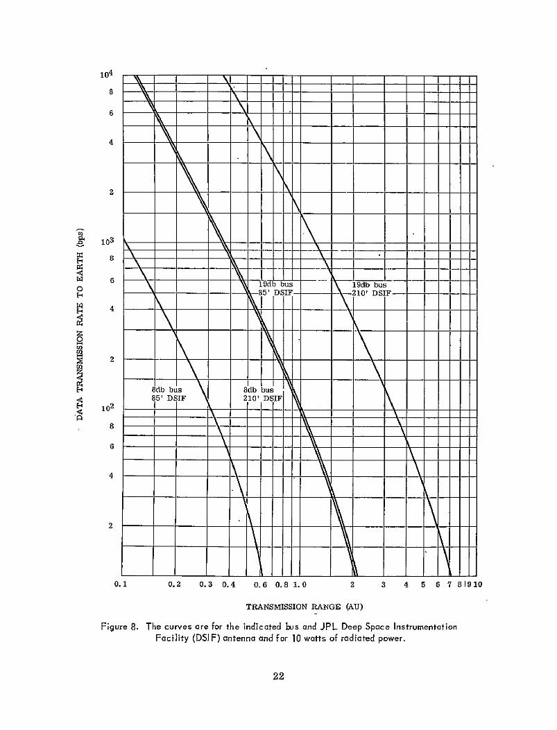
A second orbiter adjunct is a dual mode antenna see Figure 7 consisting of 32 rows of 4 colinear dipoles mounted parallel to the bus spin axis In the low gain mode the linearly polarized antenna radiation pattern is doughnut shaped with its principal axis coinciding with the orbiter spin axis Antenna gain is 8 db beam width is 15 transmission rates to Earth are shown in Figure 8
In the 19 db high gain mode the 3600 azimuth coverage of the doughshynut pattern is shrunk to 10 The resulting 100 by 150 unidirectional radiation pattern is electronically despun using the sun signal as an azimuth reference and is pointed to a fixed direction in the
19
--
COMMUNICATION FIELD INTENSITY
TOP VIEW SIDE VfEW
100
LOW GAIN 19db HI GAIN
8db SHI GAIN 150
$ LOW GAIN
CIRCULAR ARRAY ANTENNA
HYDRAZINE
TANKS--
SOLAR CELL ARRAY
EXPERIMENT SHELF
KEXPERIMENT amp INSTRUMENT COMPARTMENT
THERMAL LOUVERS RETRO-MOTOR
Fgure 7 A Venus orbiter configuration suitable for fields particles and aeronomy experiments The left side is shown in cut-away
ecliptic plane By Earth command using the bus omni-directional antenna the despun high-gain beam is changed in azimuth until it is directed at Earth Subsequent shifta in direction of the beam are made as required by the change in Sun-Venus-Earth angle With time
20
Table 3
Fields Particles and Aeronomy Orbiter Weight Summary for a 1976-77 Mission
Item Pounds
Structure 612 Experiment booms 120
Thermal system 195 Communications system 293
Data storage and encoding 245 Attitude-determination system 95 Power system
Electronics and batteries 198 Solar array 221
Programmer instrumentation 40 Cabling 150 Planetary-insertion motor dry weight 382
Hydrazine system Fixed dry weight 146 Tanks and pressurant 133 Unusable propellant 20
Subtotal 2850
Contingency (approximately 10 of subtotal) 230
Subtotal 3080
Experiments (20 contingency) 500
Total in-orbit spacecraft dry-weight 3580
Propellants Fixed attitude and spin control 110
Mission-dependent propellants Trajectory correction (in transit) 440
Orbit maneuver (in Venus orbit) 350 Planetary insertion solid propellant 2850
Total spacecraft liftoff weight 7330
1976-77 mission launch capability 7330
21
104
8
6
1ol- _shy
103
0-
z E- 4
-
-
19db bus 85 DSIF-
____-shy
ldb bus210 DSIF- -
H 8db bus 85 DSIF
8db bus 210 DSIF
6shy
2
01
Figure 8
02 03 04 06 08 10 2 3 4 5 6 7 81910
TRANSMISSION RANGE (AU)
The curves are for the indicated bus and JPL Deep Space Instrumentation
Facility (DSI F) antenna and for 10 watts of radiated power
22
Command access to the orbiter bus will be available at all times through the use of the two boom- mounted omni-directional antennas shown in Figure 15
254 Orbiter Thermal Protection
Cooling when in the shadow of Venus and additional heating due to Venus infra-red emission and to sunlight reflected from Venue are experienced by the orbiter The extent of the problem depends upon inclination of the orbit plane to the Venus-Sun line and upon the periapsfs and apoapsis distances Solar cell temperatures of 1100C to -80degC occur for the orbiter which has a 1000 km periapsis over the subsolar point of Venus and a 10000 km apoapsis A temperashyture change of less than 60C occurs when the orbit plane contains the terminator circle and is thus at a right angle to the Venus-Sun line Solar cell temperature extremes are found however to be tolerable and sufficient isolation of the instruments from the tempershyattre extremes can be obtained
255 Lifetime in Orbit
Lifetimes in orbit of 8 months are feasible
26 BUS DEVELOPMENT STATUS
The GSFC Planetary Explorer Phase A report (Reference 1) and the AVCO study (Reference 2) indicate that the proposed bus vehicle can be built using available flight-proven or flight qualified systems subsystems and composhynents Although additional development of items such as the solid-state transmitter the data-storage system the course-correction system and the electronically despun antenna would improve the bus performance and reliability these systems exist and meet the bus requirements
Additional contract study (Reference 3) is at this time directed to the imshyprovement of the P E bus and to simplifying its conversion to the different requirements of the mission-series
23
3 AERONOMY AND METEOROLOGY PROBE MISSION
31 MISSION SUMMARY
Ten days before Venus encounter the bus spin axis is reoriented to lie in the transit-orbit plane the spin rate is increased to 100 rpm and three small 52-pound entry probes are released tangentially see Figure 9 The probes impact on Venus in the region of the sub-solar point the anti-solar point and the north pole point respectively see Figure 10 During their 15 hour descent from 70 km to the surface see Figure 11 the probes will be used to make measurements of atmospheric pressure atmospheric temperature and the Earth directed component of the horizontal wind
Following small probe release the bus is retargeted to the large probe entry location and the 380 pound large probe is released toward Venus
Four hours before encounter and at a distance of 15 radii from Venus the bus science measurements will begin and will continue to an altitude of 130 km where communication with Earth is lost due to overturning of the bus as it enters the dense atmosphere Bus science-instruments will measure the neutral and ion atmospheric-composition electron-density and electron temshyperature solar wind and Venus magnetic field
The large entry probe will make measurements in the region from 70 km to the surface It will provide measurements of atmospheric pressure temshyperature and gas composition solar radiation flux and upward thermal radishyation flux cloud particle composition number-density and size horizontal wind speed and altitude above the surface The large probe is turned on by a timer 5 minutes before its deceleration by the Venus atmosphere Decelershyation measurements recorded by the large probe in the region 130 to 70 km will be used to compute the pressure temperature and density profiles needed to join the profiles of these same parameters obtained below 70 km to the profiles which will be obtained above 130 kn by the bus measurements
A summary of mission weights is given in Table 4
32 THE BUS
The bus and its use are described in Sections 21 and 31 and in Table 4 The bus follows the large probe on its path to Venus and enters at the same loshycation see Figure 10 The bus science measurements described in the preceeding section use instruments which have been flown on Earth satellites and space probes No special problems arise in their use and no furtlier instrument development is necessary
25 PRECDNG PAGE BLANK NOT PILMz
VENUS
TO SUN
POLAR QKI
I
I
SUB- ANTI-SOLAR SOLOR
TO EARTH RELEASE SMALL PROBES AT-10 DAYS
TO SUN
VENUS
TO EARTH
( )RELEASELARGE PROBE - START BUS MEASUREMENTS AT 15 RADII
Figure 9
26
TO EARTH
( ENTRY
MACHDEJECT 15REAR COVER
DEPLOY DROGUE PARACHUTE
TO EOPENEARTH
CA
MACH 0 7 AT 40 mby 1 = 70km t 0 M1AINPARACHUTE
DISCARD AEROSHELL
START ONE HOUR OF MEASUREMENTS
DISCARDEDIPARACHUTEI
P A TM OSPHE RE = 50 k t = I HR DISCARD PARACHUTE FOR FASTER DESCENT
IMPACT t= 15 HR
LARGE PROBE MAKES MEASUREMENTS
( ) MACH 07 AT 4011b t =0 JETTISON BACK COVER START TRANSMISSION
SMALL PROBES MAKE MEASUREMENTS
Figure 9 (Continued)
27
N
740K T gt 728K
AVER3kGE PLANET TEMPERATURE
740 K 900W shy
120 30--HOT -- POINT
65degW1N V -
SUN- V6 V4 )oN v6
EARTH
-Figure 10 Small probe (S) large probe (L) and USSR Venetp probe (V) landing points andrcdar feature positions are shown The Veneroapositions on the left are the points -of impact on the surface and can be described in latitude and longitude with reference to the equator and radar feature a F The Venerc positions on the right are given in solar or meteorological coordinates at the time of entry Most of the radar features ore on the far side of the planet Temperatures were obtained by Sinclair et al (Reference 3) Maximum brightness temperature difference between the htotand cold toints was found to be 184 T 92K
33 THREE S1ALL PROBES
331 Purpose
Inconjunction with the large probe the three small probes detershy-mine whther diurnal variations exist in the -altitude profiles of atshymosphdric temperature and whether the altitude profile of polar temperature differs from the profile obtained at the equator flgshyure 10 shows recent planetsurface temperature measurements and their reition f the small p6be entry positions
28
6250 1I I I i
40 I -
30
20
10
6200
BASED ON
Mc ELROYS -COMPUTATION
-
I-
UPPER ATMOSPHERE MEASUREMENTS
FROM BUS
go (KM)
80 70
-130 -
-- - - - -
o
--
6O
6150
40
-
-90-
DECELERATIONDATA STORED ON
LARGE PROBE FOR-REPLAY LATER
o 30 -~DATA20 -70 bull-o MARINER 5 ATMOSPHERES
-
- 6100
90
80
70 -
53
37
22
----IVENUS 4 5
-DATA
6
0 8
- 2 2
SMALL PRBESsectAND LARGE PROBE
TRANSMIT TO EARTH
60
6050 O -- IRADAR SURFACE- -109- -
100
I
200
I
bull--300
I
400
[
500 O0 K
IOTHERIVL
600 700 - -
ADIABATIC
800 900
TEMPERATURE OF ATMOSPHERE
29
Table 4
Mission Weight Summary
Item Pounds
Bus science 25 Bus total 304
Large probe science 70 Large probe total 380
Small probe science 3 x 4 12 Small probe total 3 x 52 156
Total science weight 106
Total system weight 840
1975 Delta launch capability 844
The small probe temperature measurements and the measurement of their Earth-directed component of wind drift will assist in deshyfining an atmospheric circulation model
332 Probe Release
Immediately before small probe release the bus spin-rate is adshyjusted so that the tangential velocities of the small probes at the time of their release will take them to their required Venus impact points Proper targeting of the small probes can be achieved by commands to the bus which (a) change its spin rate (b) change the phase of its rotation with respect to the sun at the instant of release and (c) change the number of days before entry at which release occurs The errors in release are plusmn1 deg in azimuth angle 06 in speed and 10 - 3- sec in time Uncertainty in the position of the bus at the time of small probe release is 100 km
The rotation rate of a small probe remains unchanged by separation Since atmospheric entry requires a low spin rate in order to assure rapid angle of attack reduction the probes are de-spun to 15 rpm by means -of a yo-yo just after release from the bus
30
333 Landing Points
All three small probes transmit directly to Earth and it is the comshybination of attenuation and defocusing of the radiated signal by the dense Venus atmosphere at low Earth elevation angles which deshytermines how closely the probes can be landed to the desired subshysolar anti-solar andpolar points The two effects establish the requirement of a nominal beam elevation of 256 or more above the Venus surface Probe skip-out which occurs for entry angles less than 140 is not a problem since gravitational bending of the trajectory insures entry angles of from 25 to 800 under all conditions where the 250 communications requirement is met
334 Probe Configuration
The configuration is shown in Figure 12 Probe hypersonic and subsonic ballistic coefficients m(Cd A) are 08 and 11 slugsft 2 respectively
Pressure and temperature sensitive components of the probe inshystruments are enclosed in a thick-wall aluminum pressure vessel capable of withstanding an external pressure of 200 atmospheres (3000 psi) The pressure vessel is filled with sulfur hexafluoride at 15 psi in order to inhibit voltage breakdown and to allow convective heat transfer to assist in preventing instrument hot spots Sodium sulfate dekahydrate which changes from a crystalline solid to a liquid at 3280C is used within the pressure vessel to absorb both heat generated by the probe instruments and heat entering the vessel from outside The pressure vessel is attached to the aeroshell by a thermal isolation ring and is surrounded by a blanket of high temperature high pressure thermal insulation t Release of the back cover deploys the temperature sensors Small probe weight breakdown is given in Table 5
335 Communication
Communication is direct to Earth by means of a 2300 MHz S band solid-state transmitter radiating 2 watts and transmitting at 1 bps to the DSN 210 ft antennas
The path angle above the surface at entry tMin-K(TE) consists of submicron silica particles an opacifier to minimize radiation transfer and silica fibers for reinforcement It has the lowest thermal conductivity of any non-vacuum insulashytion has low outgassing low linear shrinkage is load bearingand may be moulded and machined
31
COMMUNICATION FIELD INTENSITY
6 6 5 db
1 SURFACE APPROACH INDICATOR 5 STRUCTURAL INSULATION RING ANTENNA FEED 6 AEROSHELL - TITANIUM HONEYCOMB
2 TIMER TRANSPONDER 7 HEAT SHIELD-CARBON PHENOLIC TEMPERATURE GAUGE ELECTRONICS 8 TEMPERATURE GAUGE (DEPLOYED) PRESSURE GAUGES (3) BATTERY 9 THERMAL INSULATION IMPACT INDICATOR ELECTRONICS 10 REAR COVER
S PHASE CHANGE MATERIAL 11 COMMUNICATION LOOP-VEE ANTENNA 4 PRESSURE VESSEL
Figure 12 Small probe configuration
Transmission starts 5 minutes prior to entry blackout in order to assess whether all instruments are operating properly and to allow adequate warm-up
32
Table 5
Small Probe Weight-Breakdown
Item Pounds
Science instruments 38
Communication system 50
Power system 147
Pressure vessel heat sink and insulation 119
Heat shield and structure 124
Contingency 44
Total weight on bus -- 522
336 Measurement
The small-probe science-instruments comprise
a A temperature gauge withtwo ranges 200-500 K and 500-800 K and automatic range switching
b Three pressure gauges with ranges of 0 to 15 0 to 15 and 0 to 170 atmospheres The output of a single gauge only is transmitted and gauge switching proceeds automatically
c A surface approach indicator with a range of 200 meters The indicator which excites the aeroshell for use as an antenna will inject at least three consecutive approach indication signals into the data stream just before the small probe impacts Loss of the small probe signal will then be known to have been due to impact on the surface rather than due to probe failure
Approximately 250 temperature measurements and 250 pressure measurements will be obtained during small probe descent The interval between successive pressure measurements will be about 15 km at 70 km and 005 km at the surface All data will be encoded in 8 bit words
33
337 Winds
If large vertical winds are absent at the small probe descent posishytions avertical profile of the Earth-directed-component of the horizontal drift speed of the descending probe can be obtained from the Doppler shift of the probe transmitter frequency This singleshywind-component profile can be of value in selecting among possible circulation models In Figure 13(a) the Earth-directed-component of the wind speed obtained for the sub-solar and anti-solar probes has a maximum horizontal-component roughly equal to the true horizontal-wind velocity while the wind-velocity component obshytained from the polar probe is small In Figure 13(b) the situation is reversed with small indications from the sub- and anti-solar probes and a polar-probe Earth-directed wind-component which has a maximum horizontal-component roughly equal to the true horizontal wind-velocity
LRPOLAR P LAR
POESBEPROBE E H PH PROBE
LARGE PROBERT LARGE PROB-EARTH
POINT ANTIT
(a) (b)
Figure 13 Two possible atmospheric circulation models The models are used for illustration planet rotation and the pattern of solar energy penetration may lead to a more complex circulation pattern The Venus surface moves under the terminator at 4 ms or 310o per day
84
The accuracy with whichthe Earth-dfrected component of the horishyzontal wind can be measured depends upon
a The error in the measured probe Doppler-rshift If a turn-around transponder is used on the probe the error is small For the small probes which use a crystal controlled transmitter Doppler error is considerably larger due to frequency drift
b The error in our knowledge of the Earth-Venus departure speed at the time of measurement in the rotational departure speed at the probe entry position and in the rotation departure speed at the Earth radar location The error in the rotational departure speeds is negligible
c The speed of any vertical winds For the small probes vertical winds which are less than 05of the probe descent speed cause a negligible error
d The error in our knowledge of the probe descent speed This error is large and arises mainly from uncertainty in the computed atmospheric density and the uncertainty inthe ballistic coeffishycient of the probe following the loss of heat shield material by ablating during entry
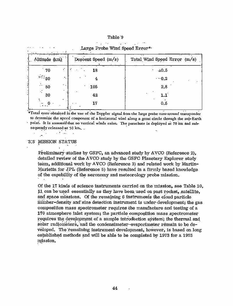
Table 6 shows the resulting total error that would be obtained in the use of the Doppler signal from a small probe to determine the speed of a horizontal wind directed along a great circle through the sub-Earth point
Table 6
Small Probe Wind Speed Error
Altitude (kin) Descent Speed ms Total Wind Speed Error (ms)
70 176 56
50 38 24
30 155 19
0 6 16
Total error obtained in the use of the Doppler signal from a small probe transmitter to determine the speed of a horizontal wind directed along a great circle through the sub-Earth point It is assumed that no vertical winds exist
35
If as has beensuggested a 4-day high-altitude retrograde wind exists conversion of the probe Doppler measurement to an equatorial wind at 70 kmaltitude would yield a wind speed of 110 plusmn 6 ms The measurements will confirm or refute the existence of winds of this speed along equator
Short-period changes in Doppler shift are independent of transmitter frequency drift and can be measured more accurately than the abshysolute Doppler shift Thus the Earth-directed speed-component of turbulence induced motions of the small probe can -bemeasured to within -40 cmsec
34 THE LARGE PROBE
341 Purpose
The large probe is designed to accomplish the principal mission objectives It examines the Venus cloud cover to discover (a) the degree to which it is penetrated by solar fluxfrom above and by thermal flux from below (b) the variation in size and number density of its particles -with altitude and (c) the materials of which it is composed Other uses include obtaining detailed altitude-profiles of atmospheric temperature and pressure starting from the surface obtaining more precise measurement of atmospheric gas-composition and searching for trace constituents measurement of horizontal wind speed during descent and determining the scale of surface physical features in the vicinity of the impact point In conjunction with the small probe measurements large probe measurements will assist in defining the diurnal temperature variation the polarshyequatorial temperature variation and the atmospheric circulation pattern
342 Separation From the Bus
Following small probe release the bus is retargeted and despun the- explosive bolts holding the large probe to the bus are fractured and springs force a separation of the probe from the bus at 1 metersec
343 Entry and Descent
During entry black-out there is on-board storage of probe decelerashytion measurements for replay during descent Parachute deployshyment is shown in Figure 9 Discarding of the aeroshell permits the
36
use of downward-looking optical andradar measurements The slowdescent obtained by use of a parachute permits extensive measurements in the region from 40 mb to one atmosphere The time that can be spent in this region is determined by parachute weight internal heating and battery weight considerations At lower altitudes however the high ambient atmospheric temperature requires a faster descent and the parachute is released Descent speeds are given in Table 9 Fins see Figure 14 are attached to the probe in order to obtain the probe rotation required by the solar radiometer at high altitudes and by the drift radar at lower altitudes To permit rotation the main parachute is attached to the probe by means of a swivel
8 (D
601
COMMUNICATION FIELD INTENSITY
I INSTRUMENTATION AND ELECTRONICS 10 PARACHUTE CANISTER RELEASE
2 EQUIPMENT SHELF 11 PARACHUTE TIEDOWN S PHASE CHANGE MATERIAL 12 REAR COVER AND HEATSHIELD 4 pRESSURE VESSEL 13 ANTENNA-CIRCULAR APERTURE 5 THERMAL INSULATION 14 MAIN pARACHUTE
6 SUPPORT STRUCTURE 15 REAR COVER EJECTOR 7 AEROSHELL 16 AEROSHELL EJECTOR 8 HEATSHIELD 17 SPIN FIN REQD
9 PARACHUTE CANISTER 18 RADAR ALTIMETER ANTENNA 19 CLOUD PARTICLE COUNTER
Figure 14 Large probe configuration
37
344 Large Probe Configuration
The configuration is shown in Figure 14 Probe hypersonic ballistic coefficient is 05 slugsft 2 Ballistic coefficient with the main parachute attached is 001 slugsft 2 When the main parachute is jettisoned at 50 km the ballistic coefficient of the sphere-cylinder descent vehicle is 8 slugsft 2
The structure of the pressure vessel is similar to that of the small probe pressure vessel described in Section 334 Large probe weight-breakdown is given in Table 7
Table 7
Large Probe Weight-Breakdown
Item Pounds
Science 70
Transponder and antenna 11
Power and data handling 40
Pressure vessel 55
Insulation and heat sink material 28
Aeroshell and miscellaneous structure 62
Heat shields (fore and aft) 46
Separation hardwaxd 6
Parachute (40 ft dia) and mortar 35
Contingency 27
Total weight on bus 380
345 Communication
Large probe communication is direct to Earth by means of a 2300 MHz Sband solid-state turn-around transponder radiation 10 watts and uses the DSN 210 ft antennas Transmission starts at 80 bps 5 minutes prior to entry black-out in order to assess whether all instruments
38
are operating properly and to allow adequate warm-up Following
parachute release at 50 km the transmission rate is reduced to 40 bps
346 Measurements
3461 Acceleration The accelerometers measure probe deceleration in the region from 130 to 70 km and the measurements are stored for replay during the latter part of parachute descent The acceleration measurements are used with measurements of the mean-molecularshymass of the atmosphere the computed altitude versus time profile and the computed probe ballistic coefficient to construct the profiles of atmospheric pressure temperature and density This information bridges the gap between 130 km where bus measurement of upper atmosphere parameters ceases and 70 km where lower altitude measurements start during parachute descent
3462 Pressure The five pressure gauges used will have ranges of 02 08 4 25 and 170 atmospheres In order to reduce the amount of information required to be transmitted pressure actuated range switching will be used Measurement error before telemetry will range from 12 to 1 of full scale for each gauge The altitude interval between pressure measurements is given in Table 8
3463 Temperature A single temperature sensor -wil be used with temshyperature switched ranges of 200-300 300-400 400-600 and 600shy900degK Measurement error before telemetry will be Z05 of the temperature range or plusmn050 for the two low temperature ranges and 615 0 for the high temperature range
3464 Atmospheric Gas-Composition The mass spectrometer inlet comshyprises an inlet break-off system a calibrated leak leading to a balshylast volume and a second calibrated leak leading from the ballast volume to the mass spectromemter ionizing region The principal constituents of the atmosphere will be more accurately defined and a search will be made for trace constituents in the range 1 to 90 AMU
3465 Water Vapor The sensing element is a water vapor sensitive capacitor comprising a 10 x 5 x 01 mm strip of anodized aluminum coated with a thin vacuum-deposited layer of gold The gold layer is porous and allows rapid diffusion of water vapor in and out of the aluminum oxide with a resulting response time of a few seconds throughout the range of the instrument The instrument is capable of measuring dew or frost points at -110 to +20 0 C (164-2941K) corshyresponding to water vapor pressures of 10 to 10 - 5 hnb or water vapor densities of 20000 to 001 microgramliter of water
39
Table 8
Typical Sampling Intervals The intervals are for a descent speed of 15 ms and a transmission rate of 80 bps and can be converted linearly for other
descent speeds (see Table 9) and for 40 bps transmission
Sample IntervalParameter
Pressure I
Temperature I
Atmospheric gas composition (1-90 AMU) 1
Water vapor (hygrometer) 03
Thermal radiation (upward flux) 01
Solar radiation (4Tw steadians and 4 wavelengths) 1
Cloud backscatter (nephelometer) 01
Cloud particle number-density and size 01
Cloud particle composition (3-300 AMU) 75
Condensationevaporation 16
Altitude (radar) 05
Recent experiments indicate no temperature dependence from -110 to +850C (164-3590K) Nor is there dependence upon total ambient pressure over a range of 10-6 to 100 atmospheres Maximum error is 2 in indicated dewfrost points The sensor is unaffected by the presence of a variety of other gases and is also capable of measuring the water vapor pressure in liquid hydrocarbons as well
The range of operation on Venus is expected to be from 40 to 100 km altitude (6090 to 6150 km radius)
3466 Thermal Radiation The thermal radiometer is mounted looking downward In a near adiabatic atmosphere the difference between the brightness temperature measured in a CO2 window at 71L and a C02 absorption region at 10A is proportional to the transmission
40
characteristics of the clouds Small differences correspond to opaque clouds large differences to thin or absent clouds The inshystrument thus provides a vertical profile of effective cloud density and will detect whether stratified condensableclouds exist or whether there is a continuously distributed dust cloud
The-experiment provides a remote surface temperature measurement just before probe impact
3467 Solar Radiation The field-of-view of the radiometer is divided into five 300 conical sections starting at 20 from the zenith and extendshying to 100 from the nadir Probe rotation results in almost spherical coverage Beam splitting allows the separation of each of the 5 light inputs into 4 different wavelength ranges for a total of 20 different input signals These 20 measurements are made every 600 of probe revolution or 6 times per revolution
The divergence of the solar flux which is derived from these measshyurements represents the fundamental dynamic drive of the atmosphere
3468 Cloud Back-Scatter (Nephelometer) The nephelometer measureshyment of scattered light gives an indication of cloud density and reflectivity Measurement during descent will indicate whether the cloud cover is a stratified condensable or is a continuous dust cloud
3469 Cloud Particle Number Density and Size Individual cloud particles will be both counted and measured by optical means in the size range 1 to 250 microns and all particles greater than 250 microns in size will be counted The instrument now under development observes the shadows of the particles against a fiber-optic detecting mosaic a method which is tolerant of background light
34610 Cloud Particle Composition In addition to the gas-source mass spectrometer which is also to be used to analyze evaporated conshydensate from the cloud particles the large probe must carry a solid-source mass spectrometer to analyze cloud particle nuclei and dust cloud particles which may consist of salts or mineral materials from the surface It would be desirable to measure masses in the range of 3 to 300 atomic mass units Preliminary studies must be concerned with developing techniques for collecting evacuating and evaporating the sample The particle collection system must comprise a collector tube filters high temperature stepping units high temperature solenoid valves and ballast volumes Prior to its presentation to the mass spectrometer the
41
sample will be placed in a chamber in which condensate material will be evaporated The gases from this evaporation will be analyzed in the gas mass spectrometer Presently untreated rock minerals are analyzed using spark-source mass spectrometry Modification of bulky spark generating equipment to a suitable size and power rating may be possible An alternate method is the use of a laser beam to evaporate the sample The presence of sample material in the laser beam could be determined by measuring light scattered from the sample
Sample vaporization would take place outside the pressure vessel and in order to minimize loss of sample through condensation the sample injection tube must allow a straight-line path from the vaporized sample to the ionization region of the mass spectrometer located in the pressure vessel
A possible alternative to the use of mass spectrometry is the bomshybardment of the sample with electrons and the identification of the sample by detection of X-ray fluorescence or Auger electron emission
34611 Condensation-Evaporation A typical instrument comprises a light source and a small reflector external to the pressure vessel The image of the source is reflected into the sphere where it is observed by a photocell The small reflector is cycled in temperature every 300 seconds from 250 K below to 25 0K above ambient temperature and then to 25 0K below to start the cycle again Atmospheric gas is dust-filtered and directed at the reflector The photocell obshyserves changes in the reflected light resulting from
a Dew forming on the mirror The temperature of the mirror at which a liquid forms is compared with the ambient atmospheric temperature to determine the percent of saturation of the atmosshyphere by the liquids vapor
b Frost formation The temperature at which frost occurs is either the sublimation temperature or the melting temperature of the material Sublimation temperatures can be identified by the absence of a liquid phase Measurement of the melting temshyperature assists in the identification of the condensate since there are a limited number of plausable substances with melting points lying within the uncertainty of the melting-temperatureshymeasurement
42
34612 Altitude and Drift Radar The altitude radar is a conventional S-band FM unit with a downward looking antenna Altitude range is 6 km Altitude measurement error will be plusmn100 meters or less before telemetering Descent speed error will be +10 cms or less Countshying techniques can be employed if smaller error in range and descent speed are desired For various combinations of horizontal wind speed and surface feature dimensions a crude description of the physical features of the surface may be possible by combining the altitude and drift radar measurements
The drift radar is a conventional S-band FM unit mounted within the large sphere and with transmitting and receiving antennas looking30 down from the horizon Maximum range of the unit will be 6 km Error before telemetering will be plusmn100 meters or less Probe roshytation rate near the surface is 15sec and each measurement will include a 4 second or 600 count of the Doppler frequency difference The use of counting will permit measurement of drift speeds as low as 2 cms with an error of +1 cms Maximum drift speed measshyurement will be set at 2 ms
Range measurements by the drift radar may enable the identificashytion of surface physical features
34613 Carrier Transponder Large probe speed-measurement during descent utilizes a carrier transponder In the absence of horizontal winds on Venus this instrument will permit Doppler measurement from Earth of probe descent speed to within plusmn3 cms Thus turbushylence or vertical wind changes of this magnitude will be measurable The error in the use of the transponder to determine the true vertical wind-speed is for the most part determined by the errors in the measured atmospheric density and in the post-flight knowledge of the probes ballistic coefficient The resulting error is roughly 125 of the probes descent speed From Table 9 we see that at 50 km the error in the vertical wind speed measurement would be approximately +10 cms before parachute release
In the absence of vertical winds the error in the measurement of the horizontal speed of the large probe along a great circle through the sub-radar point is given in Table 9 Vertical winds which are less than 05of the probe descent speed cause a negligible change in the speed errors given in Table 9 Thus for winds greater than the largest of the error values given in Tables 6 and 9 components of the horizontal wind speed over the altitude range 0-70 km will be measured by 4 probes (one large three small) at 4 different posishytions on the planet
43
Table 9
- Large Probe Wind Speed Errorshy
- Altitude () Descent Speed (ms) Total Wind Speed Error (ms)
70 C C 18 -=05
50 -02
50 105 28
30 42 11
-- 17 05
Total error-obtained inthe use of the Doppler signal from the large probe turn-aound transponder
to determiie the speed component of a horizontal wind along a great circle through the sub-Earth poinL It is assumed that no vertical winds exist The parachute is deployed at 70 km and subshysequently released-at 50 kmshy
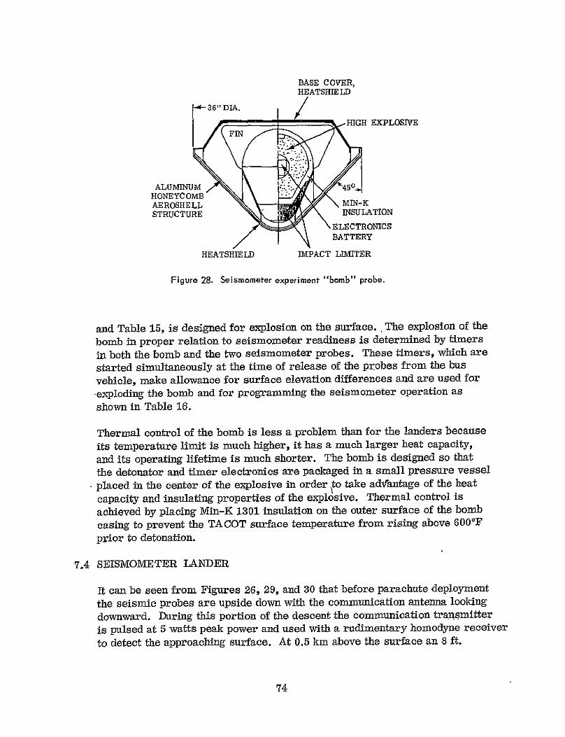
375 MISSION STATUS
Pieliminary-studies by GSFC an advanced study by AVCO (Reference 2) detailed review of the AVCO study by the GSFC Planetary Explorer study team additional work by AVCO (Reference 3) and related work by Martin-Marietta for JPL (Reference 5) have resulted in a firmly based knowledge of the capability of the aeronomy and meteorology probe mission
Of the 17 kinds of science instruments carried on the mission see Table 10 11 can be used essentially as they have beenused on past rpcket satellite and space missions Of the rema ni 6 instruments the cloud particle iliiber-density and size detection instrument is underdevelopment the gas composition mass spectrometer requires the manufacture and testing of a 170 atmosphere inlet system the particle composition mass spectrometer requires the development of a sample intoduction srstem the thermal and solar radionieter and the condensimeter-evaporimeter remain to be deshyveloped Theiemaining instrument development however is based on long established methods and will be able to be completed by 1973 for a 1975 mission
44
Table 10
Summary of Aeronomy and Meteorology Mission Instruments
Vehicle Instrument Weight Power Volume (in3)
(lbs) (watts)
Neutral Particle mass spectrometer 1-50 AMU 80 100 500
Ion mass spectrometer 30 10 330 PE bus Electron temperature probe 20 15 90
Solar-wind plasma probe 70 50 200
Magnetometer 50 10 130
Totals 250 185 1250
Temperature gauge (2 sensors) 12 015 60
Small probe Pressure gauges (3) 08 005 10
Surface approach indicator 20 300 160
Totals 40 320 170
Acceleromoters (4) 20 40 20
Pressure gauges (5) 13 01 10
Temperature gauge 12 015 60
Neutral particle mass spectrometer 1-90 AMU 100 120 500
Hygrometer 10 30 100
Thermal radiometer 30 30 20
Large probe Solar radiometer 40 30 100
Nephelometer 40 30 100
Cloud particle number and size 40 100 190
Cloud particle composition 3-300 AMU 200 600 500
Condensimeterevaporimeter -20 100 70
Radar altimeter (10 kin) 45 180 -100
Wind drift radar (10 kin) 45 180 100
Turn-around transponder 85 350 100
Totals 700 17925 1970
45
4 FIELDS PARTICLES AND AERONOMY ORBITER MISSION
41 MISSION SUMMARY
The orbiter shown in Figures 7 and 15 is placed in the orbit shown in Figshyure 16 with the instruments of Table [1 Mission objectives are to
a measure the detailed structure of the ionosphere and upper-atmosphere of Venus in-situ
b measure the interaction of the solar wind with the ionosphere of Venus
P determine the presence or absence of an intrinsic magnetic field for Venus and investigate the implications in regard to its internal composition
d determine the presence or absence of a magnetic bow shock and tail or wake for Venus and compare with other planetary environments in the solar system
OMNIDIRECTIONAL ANTENNA
S PLANETARY INSERTIONI SOLID-PROPELLANT
MOTOR (NOZZLE)
ELECTRONICALLY DESPUN FI GAIN ANTENNA
(PRINTED DIPOLES)
UPPER SOLAR ARRAY
EXPERIMENT AND INSTRUIE1T 7 FT COMPARTMENTS
MAGNETOMETER
LOWER SOLAR ARRAY P ~I O 150
FIELD INTENSITY
PATTERN
OMNIDIRECTIONAL ANTENNA
Figure 15 Fields particlesand aeronomy orbiter
47 XANOIt
DESPUN BEAM700bps TO 85 ANT
Figure 16 The orbit for the fields particles and aeronomy mission arriving approximately May 15 1977 A 1500 km periapsis change con be obtained when in orbit Data storage is used when Earth is occulted by Venus
e measure the interplanetary magnetic field and solar-wind plasma enshyroute to and in the vicinity of Venus and study spacecraft orbital motion to determine possible Venus gravitational field harmonics
42 MEASUREMENT
For a given selection of science instruments carried by the orbiting bus
the interval between consecutive measurements of the same parameterdepends upon the instrument measuring speed and the data storage capashy
bility If data transmission is in real time the interval depends uponinstrument measuring speed the transmitter power the transmission distances and the bus and DSIF antenna gains For the 1976-71 mission described here real time transmission by the despun bus antenna to the
85 DSIF antenna see Figure 8 allows a 2 second sampling interval With the use of the 210 antenna an 02 second sample interval is obtained
43 MISSION VARIATIONS
The removal of the 35 pounds of hydrazine fuel necessary to achieve the in-orbit periapsis altitude change of 1500 km would allow a payload increase
48
Table 11
Summary of Fields Particles and Aeronomy Orbiter Instruments
Weight Power VolumeInstrument (lbs) (watts) (in3 )
Ion-mass spectrometer 30 10 330
E 1ion-retarding potential analyzer 25 30 100
Electron temperature probe 20 15 90
Neutral-mass spectrometer 100 90 500
Neutral pressure gauge 70 30 300
Solar-wind plasma probe 70 50 200
Magnetometer 50 10 130
Plasma waves (ac electric field) sensor 25 15 100
Total 390 250 1750
Available on bus (1976-77 mission) 500 250t 2750
Also used for measuring during Earth-Venus transit
tWhen the bus is in sunlight 50 watts is available
of roughly 35 pounds for a total of 85 pounds for the 1976-77 mission deshyscribed here Increasing the apoapsis distance to 50000 km see Figure 6 allows an additional 60 pounds to be injected into Venus orbit but some of this increase must be allotted to additional bus structure and increased batshytery weight Lowering of the periapsis to 200 km at injection will also efshyfect a payload increase It appears that mission-series optimization will involve additional considerations of science objectives science instruments orbits orbit maneuvers and a science instrument capacity of from 50 to possibly 130 pounds
44 MISSION STATUS
Vast Earth orbiter experience exists both at GSFC and elsewhere in the design and use of this kind of experiment Those problems specific to a Venus orbiter have been examined in the GSFC Planetary Explorer Phase A report and additional bus design refinement is proceeding under contract (Reference 3) Present technology has been found to be adequate and it is apparent-that a number of technology development programs presently in
49
progress will further enhance the mission The state of instrument developshyment is such that for each measurement there are several competing flight tested instruments
50
5 ATMOSPHERIC CIRCULATION (BALLOON) MISSION
51 MISSION SUMMARY
Ten days before encounter two entry vehicles are released from the spinning Planetary Explorer bus see Figures 17 and 19 The tangential release veshy
deglocities of the entry vehicles carry them to entry positions 400 and 10 north of the equator and 20 on the dark side of the terminator The bus impacts the Venus atmosphere and is destroyed During terminal descent by parashychute see Figure 18 each of the entry vehicles inflates and releases three spherical super-pressure balloons The six balloons drift with the Venus winds at the 50 500 and 1200 mb levels and are tracked from Earth to determine the circulation of the Venus atmosphere The 500 and 1200 mb balloons make measurement of atmospheric temperature and pressure incoming solar radiation and outgoing thermal radiation and transmit this information to Earth
VENUS TO SUN-
- - 400 N
~
~71
TO EARTH
Figure 17 Release two balloon-carrying entry-vehicles at -10 days Eich vehicle contains three balloon-probes
51
(D ENTRY
70 KHI(j MO7 EJECT AEROSHELL DEPLOY PARACHUTE I
I EARTH
reg500mb LEVEL INFLATE AND DETACH BALLOONS
~~ ~7(D BALLOON GAS REACHES AMBIENT TEMPERATURE AND FULLY INFLATES BALLOON
BALLOON PATHS TRACKED FROM EARTH
VENUS
Figure 18 Balloon deployment
52 SYSTEM DESCRIPTION
521 The Balloons
The inelastic-envelope super-pressure balloon displaces a conshystant volume of the Venus atmosphere and thus resisting vertical winds and turbulence it seeks to float at a constant ambient atshymospheric density level If the balloon drifts across the terminator to the light side of the planet solar heating causes the gas pressure inside the balloon to increase and unless the balloon skin is of conshysiderable thickness balloon gas must be vented in order to prevent bursting As a result when the balloon again drifts to the dark side of the planet there may be insufficient pressure to maintain its enshyvelope fully extended Ifso the balloon falls and once falling will continue to its destruction in the hot lower atmosphere of Venus Of the three balloons the 1200 mb balloon is thermally protected by the cloud cover and its skin is sufficiently thick to allow use of the super pressure required for it to circle the planet A minor
52
BASE COVER~OMI4TTED GONDOLA
AND BALLOON
BASE COVER SEPARATION~STORAGE
GONDOLA AND
pARACHUTE BALLOON STORAGE
ALUNINUMnEAT SHIELD HONEYCOMB
AEROSHELL
Fgure 19 The balloon carrying entry-vehicle configuration The vehicle carries and inflates three balloons
increase in balloon skin thickness would also permit-the 500 mb balloon to circle the planet but the 50 -mb balloon is exposed to almost full sunlight and a 60 increase in balloon and inflation weight would be required to obtain a planet circling capability
Upward displacement of the balloons by vertical winds will likewise lead to increased super pressure and require venting When the vertical wind ceases the balloon will return to its former level but if its displacement was large and much venting occurred there will now be insufficient gas to maintain its envelopbe fully extended It will sink to its destruction Design of the 50 500 and 1200 mb balloons allows for vertical displacements of 12 1 and 1 kin respectively before excessive venting occurs
53
The 500 and 1200 mb balloons are constructed with a Dacron cloth to obtain the strength required by superpressure and a 00005 thick Kapton liner to contain the hydrogen inflation gas Bilaminate construction is utilized for the liner in order to eliminate pin-hole leaks Due to the low superpressure required for the 50 mb balshyloon the liner alone is sufficient to supply the required strength The 13 diameter gondola is attached to the balloon with a Dacron cone
The hydrogen gas necessary to simultaneously inflate the three balloons is kept at 4500 psi in a single carbon-filament-composite wound aluminum lined container The parachute size is sufficient to limit forces on the balloons to 1 psf during inflation and before separation
At floating levels above 50 mb balloon system weight becomes proshyhibitive Below 1200 mb ambient temperature is too high to allow the use of conventional materials and components
522 Communication and Tracking
Communication will occur at an initial distance of 65(10)6 km for the 1978 mission opportunity and will be able to be maintained to within 10 of the limb of the planet as viewed from Eartht The 2300 MHz S band turn-around-transponder on the balloon gondola will radiate 5 watts and will be based on 1975 technology In order to reduce weight the gondola with its transponder and science inshystruments is constructed as a unit and potted in foam rather than employing a conventional modular construction Because of the low ambient temperature at 50 mb a radio isotope heater is to be used to keep the batteries of the 50 mb balloons at operating temperature System weights are given in Table i2
Each hour the receiver on the 50 mb balloon will be turned on and it will switch to one and then to the other of its two antennas see Figure 20(a) in a search for an interrogation from Earth Intershyrogation however will normally occur every 5 hours when the receiver sensing interrogation will switch to that antenna receiving the largest Earth signal Coherent transponder operation will begin with a 01 minute lock-on time followed for 15 minutes by a return of the ranging signal to Earth The receiver will then switch if not already connected to the vertically polarized antenna for a 15 minute polarization measurement transmission to Earth The use of ranging and polarization information for tracking is shown in Figure 20(b) Ranging places the balloon on a circle about the
21 and 33 ozsq yd respectively tCommunication and tracking will use the DSN 210 ft antennas
54
Table 12
Summary of Circulation (Balloon) Mission Instruments
and Weights for the 1978 Mission Opportunity
Floating level 50 mb 500 mb 1200 mb
Planet radius 6120 km 6107 km 6101 km
Altitude (R0 = 6050 kin) 70 57 51
Instruments Turn -around-transponder
Pressure gauge Temperature gauge Solar flux (incoming) Thermal flux (outgoing)
Water vapor
Balloon diameter 185 ft 10 ft 75 ft
Balloon and cone weight 57 lbs 69 lbs 57 lbs
Hydrogen gas weight 11 15 12
Gondola weight 162 190 150
Floating weight 230 274 219
Total for balloons for two entry vehicles 2 x 72 144 lbs
Gas storage tank and accessories 2 x 55 110
Parachute and miscellaneous 2 x 10 20
Aeroshell and accessories 2 x 80 160
Mounting 52 486
10 contingency 49
Weight mounted on bus 535
Basic bus (includes 10 lb contingency) 265
Total launched weight 800 lbs
55
CIRCULAR POLARIZATION
85 db 50o
- 700
TWO X __ -900 VERTICALPOLARIZATION
VERTICAL pOSITION
FIXES POLARIZATION
(a) BALLOON FIELD INTENSITY PATTERN (b) TRACKING GEOMETRY
Figure 20 Balloon tracking is accomplished by Earth-based ranging and measurement of the polarization angle of the signal received from the vertically polarized 6al loon radiation Ranging error is plusmn 15 km at Earth Polarization angle measurement error is plusmn 10
sub-Earth point Polarization measurements identify two possible balloon positions on the ranging circle Knowledge of the balloon history determines unambiguously which is the true position
The tracking procedure for the 500 and 1200 mb balloons is the same as for the 50 mb balloon On these balloons however the science measurements indicated in Table 12 are obtained every 15 minutes and stored for replay during the interrogation period which occurs every 5 hours Data words of 8 bit length are transshymitted at 20 bps following the 15 minute ranging transmission and before switching to the 15 minute vertical polarization transmission Data transmission requires an additional 15 minutes for a total transmission time of 45 minutes Total battery capacity is sufshyficient for 6 days or 30 transmissions Depending upon the extent of solar energy penetration as determined from the earlier meshyteorology probe mission solar cells may be used to obtain a longer transmission life
Tracking will permit calculation of the average wind speed between interrogations separated by 5 hours or more Doppler measurement however will permit the measurement to within several centimeters per second of the Earth-directed component of the motion of the balloon over a period of 1 to 4 minutes
56
53 ALTERNATE MISSION CONFIGURATIONS
The final configuration of the balloon mission is greatly dependent upon the results of the aeronomy and meteorology probe mission Should this earlier mission determine that emphasis should be placed on examining the temporal and horizontal distribution of the cloud at one or more levels rather than on atmospheric circulation the balloon gondola science measurements and float altitude would be modified accordingly Should the emphasis be on circulashytion measurements at one or several levels the gondola science would be removed A circulation only mission might involve entry vehicles targeted to as many as 8 different locations each carrying an 800 mb balloon with a turn-around transponder and capable of floating completely around the planet
54 MISSION- STATUS
The above mission description has resulted from a company sponsored study by Martin Marietta (Reference 6) in cooperation with GSFC Although the work is preliminary much of it is based upon an extensive study of buoyant Venus stations (Reference 7)
57 5
6 MAPPING ORBITER MISSION
61 MISSION SUMMARY
The mapping orbiter Figure 21 is placed in a polar orbit with a periapsis of 400 km at 450 N It performs as follows
a Radar-altimeter measurement is made of the Venus surface elevation or relief profile along the sub-orbit path from the pole to the equator as shown in Figure 21 and with the resolution shown in Table 13 These measurements which are made at zero angle of incidence also provide estimates of the surface dielectric coefficient from which inferences can be made in regard to packing fraction regolith thickness and rock classification Successive altimeter measurement strips are separated at the equator by the rotation of Venusbut they converge as the pole is approached providing dense coverage in this region
Radar shadow-mapping of the region enclosed in solid lines on both sides of the sub-orbit path is also obtained by the radar altimeter A single shadow-map with a known view angle permits rough estimates to be obshytained of the elevation of Venus surface features On subsequent passages the rotation of the planet surface under the orbit will cause this same reshygion to be shadow-mapped from a different angle Stereographic techniques will be used with the two mappings to determine the shapes and elevations of surface features The highly accurate elevation measurements of the altimeter along the sub-orbit path will assist with the stereographic mapping
b Passive measurements using the radar receiver only are made of the 135 cm radiation from the Venus surface to obtain Venus surfaceshytemperature-brightness mapping in the region enclosed within the dashed lines of Figure 21
c Bistatic radar measurement will be made of the specular reflection from Venus surface features which are illuminated by an Earth based radar transmitter The mapped region is shown in Figure 21
d Television pictures of cloud-top structure are taken on the light side of Venus from the north-pole-terminitor to the south-pole-terminator and from the visible horizon on the East to the visible horizon on the west Because of difficulty in illustration only two out of as many as 30 teleshyvision pictures are shown on Figure 21
PAGE JhAIVX NOT
59
BLSTATIC RADAR
S MEASUREMENT
400KmMEASUREMENT REGION FACES
PERIAPSIS
TEIMINATORRADA
MOVES BONGBUDR
TOWARD shy
1 6024 HRS SUAERTE SSATMPERTUR
MOVE S x
MEASUREMENTROUNDARYCEx0 00 K 0 D O I B
o 24 HRs timesF1 m
x
TOEARTH-
I SURFACE BRIGHTNESS TEMPERATURE
MEASUREMENT BOUNDARY TERNMTATo RAD EVSATDON
ORBI AR ORI PO
[ TO EARTHshy
-200 pROGRAMTMED
ANTENNA 00 ELEVATIONshy00
17 HR ORBIT PERIOD
50 000 Km APOAPSIS
Fgure 21 Venus mapping description
60
Table 13
Comparison of Mapping-Orbiter-Measurement Resolution and Earth-Based-Measurement Resolution
Measurement
TOPOGRAPHY Orbiter radar-shadow mapping pole to equator
Orbiter radar-altimeter
Bistatic radar specu-lar reflection mapping
Earth based radar 1969 (measured) 1976 (expected)
SURFACE BRIGHTNESS TEMPERATURE
Orbiter radar receiver 135 cm wavelength
Earth-based radio interferometry at 111 cm wavelength
1969 (measured) 1976 (estimated)
VISUAL IMAGING Vidicon television on orbiter
Telescope
(a) on Earth
(b) In Earth orbit
Horizontal Resblution Remarks
-12 x 100 km Vertical resolution 026 - 05 km
Detects Venus elevation differences of 20 meters based on averaging over 15 km dia circles at the sub-orbit point from pole to equator
100 - 200 km
-100 km (350S to 350 N) -5 km (10degS to 10N)
65 km at 600 km
1500 x 5000 km 1500 x 5000 km
2 km at 600 km
gt100 km
gt20 km
Maps on Earth side
Vertical resolution -03 km -015 km
Temperature resolution 1 - 2K 60 beamwidth
Temperature resolution (model dependent)
-7K -4K
45- field of view
At quadrature (108 kin) and based on angular resolution of 025 arcsec (atmosphere limited) 005 arcsec72aperture (diffraction limited)
Based on 8 sec of arc along the equator 24 sec of arc ih a polar direction and at inferior
conjunction
61
62 ORBIT SELECTION
Orbit selection is based upon obtaining mapping coverage and sufficient payload
Because Venus is nearly spherical an upper limit to orbit precession of less than 00040day is obtained and thus precession cannot be used to obtain mapping coverage We must depend upon the fact that the Venus surface rotates under the orbit with a 243 day siderial period The relation between orbit periapsis position and radar mapping coverage is shown in Figure 22
In Figure 23 we see that large orbit payload capacity can be obtained by increasing the orbit apoapsis altitude A slight additional increase in orbit payload capacity will also result from a decreased periapsis altitude For the 1976-77 mission considered here the 166 lb payload requires an apoapsis of 50000 km Table 14 presents the weights for this mission
63 MAPPING INSTRUMENTS
631 Radar
The radar has a range of 1500kmand furnishes 10 kw 300 ns pulses at a rate of 375 pulses per second The radar antenna shown in Figures 21 and 24 is programmed in elevation to look at the sub-orbit point during each bus rotation Beam path during rotation is shown by the dotted lines in Figure 21
A temperature calibrator is furnished to enable the radar receiver and the 5 ft diameter antenna to be used for determining the Venus surface brightness temperature by measuring Venus 135 cm radiation
The radar receiver will also be used on the Earth side of Venus for bistatic operation in conjunction with a separate S-band turnshystile -antenna system and other electronic adjuncts
Radar receiver data storage will use a modified Nimbus HDRSS tape recorder with 5 track storage totalling 6(10)8 bits and with a maximum input rate of 2(10)1 bps Two tape recorders are inshycluded The second recorder will be held in reserve
In order to insure good measurement data radar range is based on a weak diffuse reflection from
the surface In the event of a high degree of specularity radar range can be extended to include
apoapsis altitudes
62
-
NORTH
k
121 D S
BUS SPIN AXIS ALWAYS POINTS
i NORTH
-40ONx
50ON
500S
50S_
243 DY
DA Ishy
x
Figure 22 Venus radar-mapping coverage for periapsis placement at 90N ON and 45 0 N Coverage depends upon the fact that the Venus surface rotates under the orbit with the 243 day sidereal period
63
ORBaT PERIOD (HouRs)
2 4 6 8 10 15 20 25 30 35 40 190
1975 180 1976-77
o 170
F-4 160 -4
150 1981
140
S 130
120
z1978
110 Ii00
80100
- 90
o 80
o 70 400 KM PERIAPSIS ALTITUDE
60 I I I I I I I I 0 10 20 30 40 50 60 70 80 90 100 (10)4
APOAPSIS DISTANCE (KM)
Figure 23 Averaged values for payload in orbit as related to apoapsis altitude for the mappiig orbiter Reduced ppriapsis results in slight additional payload capacity For the mapping orbiter no provision is needed for in orbit periapsis change
Table 14
Summary of Mapping-Orbiter-Mission Instruments and Weights for the 1976-77 Mission Opportunity
Item Watts InP Lbs Total Lbs
Monostatic radar
Transmitter 34 300 178
Receiver 6 220 132
AD converter
Two tape recorders
5 ft dia antenna mounting and elevation drive
2
15
2 -
5 9 t
40
1180
20
300
290 _
920 92
Bistatic radar (accessories) 100 6
Surface - temperature-measurement
calibrator 2 40 2
Vidicon TV 20 850 30
273amp 130
20 contingency 26
156
Planetary Explorer bus (with propulsion) 590
Lift off weight 746
One operating at any time
tMaximum battery power required for shadow operation Available Planetary Explorer module volume 2740 in
632 Television
The vidicon television has a 15 ms shutter speed 800 line resoshylution and will present an output with 32 shades of grey Field of view is 450 and at right angles to the bus spin axis Television data will be stored on the radar tape recorder
65
I I
ELECTRONICALLY DESPUN ANTENNA FOR EARTH COMMUNICATIONS
-shy+--t--shy
-20
SI3
+ 900
RADAR ANTENNA ELEVATION IS PROGRAMMED
Figure 24 Radar dntenna deployment
66
64 STORAGE COMMUNICATION AND COVERAGE
Mapping missions are characterized by the requirement for storage transshymission and processing of large amounts of information For our first mapping-mission construction we have selected a storage capacity of 6(10)8
bits and use the PE electronically despun antenna to communicate to the DSN 210 antennas Figure 25 summarizes the mapping orbiter storage communication data and coverage relations
a Mapping days vs Earth-Venus separation distance is shown
W 28 -END OF STEREOGRAPHIC COVERAGE
o 26 - IE END OF OVERLAP OF SHADOW-AMAPPING s0 MAPPINGP4 - COVERAGE OF EQUATOR
24
12 22 - -
M4 20 Z EXCELLENT STEREOGRAPHIC
18 -- COVERAGE UP TOTHIS TIME
t 16 1-Z 14
14 5 START OF REDUCED
02Z 12 --SHADOW-MAPPINGEEQUATORAO NUMBER OF THE 6REQ(l0) IREDBITS FORshy2TRANSMITTINGORBITS
0 -OBTAINED DURING ONE ORBIT lt 10ROBI ERO
- 8
Z 4 -05
SSIDERIAL ENDS
DAY
S4 EXPERIMENT 202 3 L COMPLETEDshy
0 50 100 150 200 250 MAPPING DAYS
S I I I l i I I 045 06 08 10 12 14 L6 17 172
EARTH - VENUS SEPARATION AU
I i i I I I i 6800 4000 2000 1000 800 600 500 450
MAXIMUM TRANSMISSION RATE FOR FIXED SYSTEM (bps)
Figure 25 A summary of storage communication rate and coverage relations is shown See text for explanation
67
b Maximum transmission rate for a fixed communication system is shown vs Earth-Venus separation distance and mapping days
c As the maximum trafismission rate goes down the number of hours (or orbits) required to transmit the 6(10)8 bits of stored data increases
d As the number of transmission only orbits increases the spacing beshytween elevation measurement strips on the Venus surface increases
It can be seen for example that doubling the maximum transmission rate or halving the total data stored for transmission would halve the separation of the elevation measurement strips and insure stereographic radar mapping throughout the entire mission or if coverage were held unchanged the DSN effort could be reduced from continuous reception to half-time reception
A more advanced system configuration might replace the present fixed mounted 5 diameter antenna with a mechanically despun antenna with a proshygrammed elevation control In this configuration the same antenna would be used for both radar observation of Venus and for communication to Earth While general stereographic coverage would remain unchanged a number of advantages would accrue
a Altitude measurement strips would be able to be obtained from 90N to 30S or from 65degN to 65degS
b It would be possible to examine select objects with a 2 km by 2 km resoshylution by using the system as a coherent side looking synthetic aperture unfocussed radar
c Communication rate to Earth would increase by a factor of eight Total monitoring time -by the DSIF would be reduced by a factor of eight
65 MISSION STATUS
The above mission description incorporates the results of radar studies (Reference 8) furnished for the mission series by H J Goldman and D L Roberts
Astro-Sciences IIT Research Institute
68
While only rudimentary study has been made of the surface temperature television and bi-static radar measurements and of the structural thermal system operation and orbit problems specific to a mapping mission no unusual or disabling problems have been identified Considerable related study and experience exists for each of the proposed measurements and for the required systems
69
7 VENUS INTERIOR EXAMINATION (SEISMIC LANDER) MISSION
71 MISSION SUMMARY
Thirty minutes before encounter three entry probes are released from the spinning bus The two outer probes are released tangentially and the center probe is given a small forward separation speed The three probes enter the atmosphere near the sub-Earth point and descend together as shown in Figure 26 The bus is destroyed upon entry The bomb probe reaches the surface serveral minutes before the two seismic probes and awaits their landing The two seismic probes deploy parachutes at 05 km above the surface they land gently one and two km respectively from the bomb and uncage their seismometers The geometry of the landed positions is shown in Figure 27 Three minutes after the seismic probes land the bomb exshyplodes starting the active seismic experiment In the first 20 minutes after the explosion the seismic landers transmit the results of the explosion measshyurements to Earth while at the same time storing for replay the measurements obtained from any natural Venus quakes which occur during this 20 minute
h = 2 RADII REORIENT SPACECRAFT SEPARATE PROBES
ATMOSPHERIC ENTRY
M =06 REMOVE AEROSHE LLS
ARM ALTIMETER START TIMER AT 50 ATMOS (6060 Km)
SENSE SURFACE AT 0 5 Km DEPLOY PARACHUTES
EARTA
0 5Km AXTOUCH DOWN ELVATION SEPARATE PARACHUTE
Figure 26 Bomb and seismometer deployment
71 PRECEDING PAGE BLANK NOT FILM-Lo
TOP VIEW 20HZ MEASURED BYTRIAXIAL
SEISMOMETER RADIO RANGING AFTER EXPLOSION
-- -- -- - -----DISPEoSION - -----shy
2km
1 km DISPERSION
EXPLOSION
MEASURED BY USE OF EXPLOSION 20HZ SOUND WAVE TRIAXIAL
SEISMOMETER
VERTICAL SECTION h = 0 5km MAX
h =
0ATMOSPHERIC 0PATH
REFRACTE -- _ __ __gt _ -- 0 6 km
PROBASLE R DEPTHS
V REFLECTED 3 km
of the Venus active seismic experimentFigure 27 Geometry
During the final 40 minutes of lander life Venustransmission period quakes and atmospheric noise are monitored in real time
The active seismic experiment is intended to determine the surface structure
compressional and shear wave velocities and the elastic and anelastic The
properties of the surface material down to a depth of about 06 km
seismometers are also used during the probe life-time to measure nearby
It is possible that significantmicro-earthquakes and natural seismicity
Venus quakes will occur and p~rovideinformation aboutthe planets interior
Average and peak sound levels are also monitoredstructure
72
72 TARGETING
The placing of the bomb and seismometer probes on the Venus surface is designed to obtain a minimum dispersion about the relative positions selected for the landed probes The probes are separated from the bus simultaneously with identical spin rates they enter the Venus atmosphere at the same time with large and equal entry angles and have the same hypersonic ballistic coefficients Studies have shown that for these conditions relative dispersion during entry can be expected to be less than 20 meters
The subsonic ballistic coefficients of the probes are equal and large The probes will pass rapidly through the high atmosphere where large and variable winds may exist which if allowed to act over long periods might cause large relative dispersion
Because of equal descent speeds however all probes will always be at the same atmospheric level and thus dispersion will depend only upon the differshyence in wind speed over a horizontal distance of at most 2 km rather than upon the wind speed itself Since the winds near the surface are small changes in the horizontal distance between the landed bomb and the seismic probes due to the 2-3 minute parachute descent of seismic probes time is not expected to be significant
Total relative dispersion is not expected to impare the active seismic experiment
Knowledge of the landed geometry of the seismic experiment will be obtained by use of
a pressure measurements to determine local and relative altitudes
b microbarograph sound-arrival-time detection and pressure and temshyperature measurement to determine the over-the-surface distance of the seismometers from the bomb -and
c a turn-around 24 MHz 5 watt radio-ranging device on the seismometer probes to determine their over-the-surface separation
The sides of the landed position triangle will be measured to better than 1 if high surface features do not separate the landed probes
73 THE BOMB
Because of present uncertainty in the ability to penetrate the Venus surface to a sufficient depth to achieve good explosion coupling the bomb Figure 28
73
BASE COVER HEATSHIE LDF36DIA HIGH EXPLOSIVE
ALUMINUM 450 HONEYCOMBAEROSHELL INUATO
STRUCTURE ELECTRONICS BATTERY
HEATSHIELD IMPACT LIMITER
Figure 28 Seismometer experiment bomb probe
and Table 15 is designed for explosion on the surface The explosion of the bomb in proper relation to seismometer readiness is determined by timers
in both the bomb and the two seismometer probes These timers which are
started simultaneously at the time of release of the probes from the bus
vehicle make allowance for surface elevation differences and are used for
-exploding the bomb and for programming the seismometer operation as
shown in Table 16
Thermal control of the bomb is less a problem than for the landers because
its temperature limit is much higher it has a much larger heat capacity
and its operating lifetime is much shorter The bomb is designed so that
the detonator and timer electronics are packaged in a small pressure vessel
placed in the center of the explosive in order to take advlantage of the heat
capacity and insulating properties of the explosive Thermal control is
achieved by placing Min-K 1301 insulation on the outer surface of the bomb
casing to prevent the TA COT surface temperature from rising above 600F
prior to detonation
74 SEISMOMETER LANDER
It can be seen from Figures 26 29 and 30 that before parachute deployment
the seismic probes are upside down with the communication antenna looking
downward During this portion of the descent the communication transmitter
is pulsed at 5 watts peak power and used with a rudimentary homodyne receiver
to detect the approaching surface At 05 km above the surface an 8 ft
74
Table 15
Bomb Weight Summary
Explosive (TACOT) 500 lbs
Electronics and timer 21
Insulation 28
Electronics installation (pressure vessel and support) 19
Explosive container 70
Pressure equalizer (bellows and adaptery 8
Insulation cover 38
Aerodynamic fins and installation 16
Shock attenuator and installation 9
Impacting weight 709
Entry aeroshell 405
Structure 225
Heat shield Front cone 130 Base cover 50
Yo-yo despin system 13
Pyrotechnic system for jettisoning aeroshell (including structural adaption) 60
Entry weight 1187 lbs
75
Table 16
Mission Sequence of Events for the Assunption of a Level landing -Region at a Radius of 6050km
Time Event -Notes (minutes)
0 Start timers on 3 probes 2 see Separate probes from bus
24 Despin probes before entry 30 At M 06 sense 1 g decreasing
separate aeroshell 66 Activate altimeters on the
seismic probes 76 Deploy chute on seismic probes 775 Bomb impact 79 Seismometer touchdown
Deflect chutes 80 Begin seismometer uncaging
815 Transmit signal with pressure temperature and engineering data
82 Bomb detonation Start active datastorgeampCotine~Timersstorage 3 Continue transmission
of P T E 8225 Microbarograph active data complete
825 Seismometer active data storage complete
Initiate active seismic data transmission
Deploy W ip-afftennas for rangeshymeasurements make range iheasuirements and store them
835 Rangq measurements complete Beginpassive seismic data storage
104 Active seismic data transmission complete
Readout range data and transnit
106 Range transmissioi complete-End of active exPeriment Readout stored passiVe data
Spacecraft command Spaceoraft command BC = 0475 slugsft 2
BC-- 38 slugsft2
P = 50 atmospheres R = 6060 km BC = 022 slugsft 2
V = l3ms
V = 3 ms
30 secohds allowed for Earthstation lockon
in probes andbob
bomb
30 bps
Requires 130-sec
RequiLres 3 sec
76
Table 16 (Continued)
TimeEvent Notes (minutes)
106 Passive data transmission complete Begin real time monitoring of
seismometers nicrobardgraphs 3f bps pressure temperature engineering data
140 Design mission complete Surface operation of one 130F hour at 6050 km
42 DIA PARACHUTE FEET HEAT SHIELD
FINS
HEAT45 SHIELD
HONEYCOMB AEROSHELL STRUCTURE
Figure 29 Seismometer probe entry and descent configurations
77
SECTIOH B
Fgure 30 Seisrnometer probe landed configuration
diameter glass-fabric parachute is deployed the seismic probe is up-righted and lowered to th~e surface at low speed At touch-down the parachute is reshyleased and deflected by means of a small rocket see Figure 26 Seismic lander construction is described in Figure 30 and Table 17 The whip antenna used for radio ranging between the two seismometers is shown in Figure 30
The characteristics of the tharee axis seismometers are primarily based upon the descriptions of seismic instruments for a Viking Mars lander A three axis unit is used since lunar experience has shown that much information would be lost should only a single axis unit be used Since for short path disshytances there is little damping and high frequencies prevail a20 Hiz response is used Seismometer design will allow operation in the presence of lander tilting of 250 or at higher angles with reduced sensitivity
78
Table 17
Seismic Lander Weight Summary
Internal equipment 289 lbs
Electronics and baitery 213 Science 31 Seismic instrument 45
Pressure shell 170
Waffle shell 142 Closure flanges and hardware 28
Internal mounting structure and penetrations 58
Insulation (Min-K) and heat sink material 98
Insulation cover and closure joints 50
Landing legs fins and mechanisms 100
Shock attenuator and installation 25
Parachute system 50
Chute 25
Metallic harness and riser fairing pyrotechnics and rocket 15
Parachute can cover its deployment and landing legs lockrelease 10
Landed weight 840
Entry aeroshell 590
Structure 320 Heat shield
Forward cone 200 Base cone 70
Despin Yo-Yo system 15
Pyrotechnic system for jettisoning aeroshell 75 (including structural adaptation)
Entry weight 1520 lbs
79
Table 18
System Weight Summary
Seismic landers 2 x 152 304
Bomb 119 423
Contingency (10) 42 A65
Adapter structure and deployment mechanism 75
Contingency (10) 8
Spacecraft 266
Total launched weight 814
75 COMMUNICATION
The seismic landers both communicate directly to Earth at 30 bps by means of a 5w S-band non-coherent -ystem using a 5 db crossed-slot antenna Data encoding is at 8 bits per word The first 30 seconds of seismometer data following detonation is sampled at a high rate and stored for an irnmeshydiate 20 minute readout at the 30 bps transmission rate During this 20 minute readout period for the active seismic experiment data passive seismic data is stored and processed for transmission in compressed form at the end of the 20 minute period The last-half of the 1 hour mission is used to transmit real time data taken at the low rate of two samples per second
76 DISCUSSION
The final configuration of the seismometer experiment may depend heavily upon our knowledge of Venus obtained from preceding missions
a The meteorology probe mission will determine the severity of surface conditions by measuring surface pressure and temperature and obtaining a rough estimate of the magnitude of surface winds
Communication is to the DSN 210 ft antennas
80
b A penetrometer experiment on the meteorology probe or TV lander misshysion would explore the feasibility of use of a penierating bomb to obtain increased horizontal and vertical range for the active seismic experiment and to perform a Terradynafic experiment
c Measurements of the surface dielectric coefficient during a mappingshyorbiter mission may give information as to surface packing fraction regolith thickness and rock classification
If natural Venus quakes are found to be frequent a follow-on experiment might use a passive array of 2 or perhaps 3 seismic landers constructed with conventional thermal design to last 25-50 hours If they are infrequent then attention must be devoted to devising the high temperature equipment necessary for lifetimes of several years or more
77 MISSION STATUS
This mission was developed as a company sponsored effort by Martin -Marietta (Reference 6) It is the result of a short period but intensive apshyplication of present scientific and technical knowledge to the total problem of Venus interior examination
The estimation of surface properties down to the depth of penetration by means of examining the
acceleration profile obtained during penetration Transmission of the acceleration measurement is from a trailing wire This inmthod was developed by the Sandia Corp and has had extensive
Earth use
81
8 VENUS SURFACE-INSPECTION (TELEVISION LANDER) MISSION
81 MISSION SUMIVARY
Following entry into the Venus atmosphere at the sub-Earth position 7deg on the light side of the morning terminator and 4 south of the equator the lander discards its heat shield and descends to the Venus surface The lander radar senses the approach to the surface at 12 km altitude and causes the parachute and the lander legs to be deployed see Figure 31 On touch-down the parachute is released and is removed by means of a
ENTRY AEROSHELL DISCARDED SUBSONIC DESCENT
- PARACHUTE AND LANDING LEGS RELEASE AND DEPLOYMENT
Figure 31 Parachute and leg deployment
83 pRICEDING PAGE B3LANI(NOT FILMt f
small rocket The zenith-seeking high-gain communication antenna Figshyure 32 is uicaged and the soil sampling drill and the TV periscope Figure 33 are deployed The lander following the schedule of Table 19
a chemically analyzes two samples of the surface soil
b obtains two microscope images of the soil samples to determine their petrographic nature
c takes 10 TV pictures of the surrounding area see Figure 34 with resolutions of from several millimeters to several tens of meters and ranges of from one meter to as much as 15 km depending upon lander elevation local lighting and atmospheric conditions
d performs measurement of ambient pressure temperature and wind velocity
Lifetime on the surface is two hours
ORIENTED AN~TENNA
PRESSIE SHELL
AL8MTE ANTNN IMPACT ATTENUATOR
Fgure 32 TV lander configuration
84
MIRROR ELEVATION
j
DRILL
MIRROR AZIMUTh CONTROL
STOWED HEIGHIT
LE
A
HIGH1TEMPERATURE PERCUSSIVE DRIVE
TV
DRILL BIT
Figure 33 Soi l sampling and TV picture mechanization
Table 19
Mission Sequence of Events
Time (minutes)
Event Notes
-13 Activate altimeter (timed function)
Sense surface at 05 km
Deploy chute Deploy and lock legs
P = 50 bars R = 6060 km
BC chute = 022 sIft 2
0 Probe touchdown Release and deflect chute Deploy antenna Deploy TV optics Activate soil sampler
Nominal 6050 km surface radius
2 Take first TV picture 30 seconds allotted
25 Begin to collect and transport soil sample
Begin first TV transmission 8 minutes required
105 End TV transmission Begin transmission of P T W E Take second TV picture Begin soil analysis and store data
11 Begin second TV transmission
19 End second TV transmission Begin second P T W E transmission Take third TV picture Soil sample
20 Begin third transmission P T W fol-lowed by composition data from storage
Earth based evaluation of first two-pictures possible
28 Take fourth TV picture
Repeat sequence from 25 minutes Second soil analysis complete at 58-minutes
58 Continue pictures 8 through 12
106 Complete automatic sequence
86
Figure 34 Possible TV picture sequence Numbers 3 and 6 repshyresents microscope pictures of the soil sample viewed within the lander
82 COMMUNICATION
System design is determined by the requirement for transmission directly
to Earth for command capability and for high data transmission rate
a A sub-Earth landing point is required to minimize atmospheric attenuashytion and to simplify pointing the lander antenna
b The 18 db parabolic antenna is capable of 300 tilt It uses motor driven gimbals controlled by a sensor within the pressure vessel as a means to point the antenna to the zenith regardless of the tilt of the landed vehicle
c A 20 watt S-band transmitter is used to obtain a data transmission rate of 2000 bps to the DSN 210 ft antennas
87
d A command system is used to permit reprogramming of the picture sequence following examination of the first few pictures
Since single picture transmission time is 8 minutes and round-trip comshy-municationtime is 12 minutes roughly 20 minutes will-be required before the automatic control of the lander picture taking sequence can be intershyrupted by command from Earth Thus the first opportunity to effect picture control would occur at the beginning of the 4th of the total of 12 pictures
Three kinds of data are transmitted to Earth image data stored massshyspectrometer data and real time science and engineering data Image data is read directly from the TV storage tube in analog form for conversion to 6 bit words and placed in format for direct transmission to Earth Stored spectrometer data (3600 bits) is read out at the end of each sampling period and interleaved with the real time transmission of atmospheric pressure temperature and winds and engineering data Thirty seconds is allowed for this data prior to each picture transmission
Since pictures on Venus are expected to lack high contrast the use of TV data compression of possibly 2 to 1 must be considered as a means of doubling the number of pictures returned The use of data compression would however require a real-time reconstruction capability at the DSN in order to provide real-time picture viewing for command purposes
The radar altimeter required to provide a signal for opening the parachute at an altitude of 05 km will be provided by operating the communication transmitter in a pulsed mode and switching its output to a downward looking antenna
83 LANDER INSTRUMENTS
A summary of the instruments is given in Table 20
831 Television
The image tube is sufficiently sensitive to operate under moonlight conditions and has a silicon-target imaging tube which can store the image for more than a half hour for read-out at the desired bit rate Camera exposure will be automatically adjusted by a photomshyeter Image resolution is 400 lines and each picture element will resolve 64 light levels (6 bitspicture element) resulting in 97(10)5 bits per picture Because the camera target must remain cool light from the area of interest is collected by a mirror mounted in a boom which is extended to 45 inches above the surface This
88
Table 20
Science Payload for 1981 TV Mission
Weight Power Dimensions Bits Samples Remarks (pounds) (watts) (inches) Sample Mission
Panoramic TV
Camera system 12 14 4 x 65 x 12 972 000 10 Operates continuously
Mast and associated optics 5 - 2 dia x 37 - -
Optics 15 - - -
Motor drives 2 3 - - Total operating time 15 mins
Microscope TV
Microscope petrographic 6 3 8 x 8 x 3 972 000 2 8 minutes operating timepicture
Connecting optics 1 - 05 dia -
Sample collection and transport 6 50 small -
Mass spectrometer surface 20 50 500 in3 1600 2 Data based on massshycomposition analyzer spectrometer analyzer
Atmospheric pressure sensor 025 02 2 dia x 1 8 12
Atmospheric temperature sensor 025 05 1 x 1 x 1 8 12
Anemometer 05 12 1 x 1 x 2 8 2400 Samples 10 times second for twelve 20 second periods
Table 21
TV Lander Weight Summary
Internal equipment
Science
Electronics
External equipment
Science
Electronics
Lights
Flares and launch mechanism
Heat sink material
Insulation (Min-K at 130ft 3)
Structure a
Pressure vessel
Internal mounting structure
Soil sampler and TV mast mounting
Insulation cover
Body shock attenuator and mounting
Fins and base cylinder
Landing gear mounting brackets
Release and installation hardware
Parachute system
Chute risers
Harness pyrotechnics tractor rack
Canister cover ejection springs
Lander weight
862
479 lbs
383
188
63
66
10
44
150
250
921
320
176
24
110
13
130
12
136
63
40
14
9
2484
90
Table 22
TV Lander Probe - Total Weight Summary
Lander weight 2484 lbs
Entry aeroshel (4 12 aia 50 cone 12 angle) 980
Structure 560
Heat shield forward 300
Base heat shield 120
Pyrotechnic and Delta structure for staging 180
Despin system 30
Entry weight 3674
Contingency (10) 370
Adapter separation mechanics pyrotechnics 300
Contingency (10) 30
Inertia balance weights (to achieve required roll inertia) 480
dontingency (10) 48
4902
Spacecraft 2660
Total system weight 7562
launch capability (1981 mission) 8250 lbs
Margin 688 lbs
mirror is similar to that of the Surveyor TV camera and can be rotated around the boom axis and in elevation to scan the area
around the lander from the horizon to about 1 ft away from the surface point below the camera The same gravity sensor that is used for pointing the high gain communication antenna to the zenith may be used to adjust the TV mirror system to compensate for lander tilt By means of relay lenses and reflective optics the light from the image area is conducted to the inside of the lander and focused on the face plate of the camera tube
91
The tutral illumination of the Venus suirface will b6 known from the Vn6nuampnteoolb6gy-probe mission prior to the 1981 surface
inspection mission With suffiient natural light the visual range
could be as-far as-15 km although our present knowledge indicates that tee Would be a complete diffusion of natural light which would -destroy-all confrast except -fortt achievedby bolor or reflectivity
variations- Natural illumination reill be-used -forpictures of regions
more tha 20 fta-way from the lander and the second picture in the
assumed sequence seeFigure 34 covers-the horizon This picture
is -evalhoted on Earth and provides information about the best range
and azimuth angles-for the following pictures Ppdating of the imshyaging controller on the -ander isaccomplished by command from Earth
If natural illumination is insufficient for imaging small (05 lb)
self-propelled rocket flares will be launched possibly-from the periphery btfthe lander antemia to insure aburate launching toward
a point about 60 ft above the imaged area and 200ft away from the lander Near this point the rocket flares provide a bright 8 second
light source and illuminate equally the areas of the outer pictures 2 7 10 11 and 12 which extend to a distance of 300 ft These
images will have good shadows because of the large angle between
camera and light source
For imaging of areas less than 20 ft away from the lander image contrast can be enhanced by light sources attached to the lander Thus regardless of the amount of natural illumination reflectorshy
backed filament 4uartz lamps will be attached to the outside of the lander for use in illuminating near-by areas The 100 watt lamp corshy
responding to the programmed picture is turned on for approximately
3 seconds and during part of this time the camera tube is exposed
For petrographic microscope pictures of the sample which has been collected and brought into the pressure vessel for chemical analysis the image from the microscope is conducted to the camera by fiber optics The camera is optically coupled to the microscope by flipshyping a mirror into the light path
832 Surface sample analysis
Surface sample analysis involves sample collecting TV microscope
viewing of the sample and vaporization of the sample for mass
spectrometer analysis
92
The sample collector Figure 33_ is placed within the root of one of the lander fins and comprises a small diameter helical fluted spindle with a tungsten carbide tipped drill Spindle rotation at 8 rps is caused by a percussive drive which delivers many short duration blows causing the drill bit to generate small surface parshyticles which are driven upward by friction between the rotating particles and the tube wall Near-the top of the spindle centrifugal force puts the surface sample particles into an inclined tube and the particles drop into the sample air lock Then the -upper valve of the air lock is closed and the lower valve is opened The particles then drop onto a sample transporter which supplies the petrographic microscope and the composition analyzer
84 MISSION STATUS
This mission was developed as a company sponsored effort by Martin Marietta (Reference 6) It is the result of a short period but intensive application of present scientific and technical knowledge to the problem of Venus surface inspection
93
PART III
DISCUSSION
1 lVIISSION-SERIES OPTIMIZATION RELIABILITY LOW COST
Part 11 has presented a view of six different classes of Venus missions and has indicated the scope of their science return It is clear that despite the findings of the Mariner and Venera missions and Earth based measurements the ratio of future science return to future effort is large for Venus by comshyparison with present exploration possibilities for other planets It is apparshyent also that
a The mission series will involve many kinds of experiments from a number of different planet disciplines many different experimenters and a conshystant return of new Venus information over a number of years Experishyment planning and execution can be expected to benefit from more thought and to proceed more reliably and at less total cost
b The mission-series can be planned to allow maximum use of new knowledge in planning the next steps in Venus exploration a cost reduction feature
c The mission-series can be planned to allow for a sensible failure rate ie the use of exploratory measurements which may produce negative reshysults in order to substantially reduce total mission-series cost
d The mission-series can be planned for maximum use of commonality in order to increase the science return to cost ratio by means of lower conshystruction and testing costs and increased reliability
Additional reliability is a feature of those missions where the bus veshyhicle impacts the planet Should the command capability to the bus be lost following the third bus course-correction an automatic -probeshyrelease program will carry out the mission substantially as planned Should the automatic probe-release program fail automatic release of the probes from the bus will take place as the bus enters the sensible Venus atmosphere and although the intended probe placement will not be obtained there will be a major science return
2 INSTRUMENT STATUS
The principal task of this document was to show that it is possible to place protect operate and communicate with the required instruments Most of
95 PRECEDISG PAGE BLANK NOT FILMI
the means are straight-forward applications of present technology Protecshytion of optical windows from possible frosting for example can be obtained by focusing an infra-red spot of aperture size on the window by resistance heated apertures or by maintaining a positive air pressure in front of the window from a filtered air source With protection accomplished use of most of the instruments-pressure gauges temperature gauge nephelometer seismometer radar etc-differs little if any from past use
For some instruments however additional testing is required or mechanical and electrical adjuncts must be devised Mass-spectrometer input leaks exist which will allow continuous operation at I atmosphere and in principle they can be used for several hours at 170 atmospheres and 750 K in a simple series leak-and-ballast-volume arrangement The arrangement must be tested If leak-inputs are unsuitable then the principles of existing highshypressure metered-input gas systems must be adapted to Venus use no inshytrinsicdifficulty has been seen For a few possibly more difficult instrument uses such as a Venus surface cheniical composition -measurement suitable techniques and high temperature high pressure components have been identified
In summary most of the desired science return of the mission series can be obtained with existing instruments The necessary principles techniques and components appear to be available for obtaining all of the desired measurements
3 SYSTEM STATUS
No system design construction or operation difficulties have been identified which would render any significant part of the mission-series hopelessly inefficient or would place its achievement in jeopardy The degree to which the balloon inflation system can be reduced in weight for example will not determine whether or not a circulation mission is possible but whether 6 or 9 balloons will be released at Venus
While not all conceivable contingencies will be able to be coped with-a seismometer probe stuck on edge between two rocks will fail to communishycate to Earth-the proposed mission-series is conceived so as to suffer least on the whole from the intrusion of unlikely or unanticipated events
4 MISSION-SERIES RATIONALE
As we examine the science return contemplated by the mission-series it is clear that although the measurements of Mariners 2 and 5 and Veneras 4 5 and 6 past Earth based measurements and the anticipated Venus-Mercury
96
fly-by results have begun to excite the interest of geophysicists and represhysent a valuable starting point most of our measurement and understanding of Venus will remain to be accomplished
It is expected that additional work on the first and second phases of the study will both expand and strengthen the rationale for the Venus mission-series The work to date indicates a low-cost-efficfent -reliable sustained high yield program involving many disciplines and many scientists suitable for international participation making -maximum use of past Venus measureshyments and future Earth based inspection of Venus
The nearness of Venus to Earth and to the Sun its similarity insize to Earth its possible similarity in origin its dense atmosphere its uniform cloud cover its high surface temperature and its slow rotation make Venus the most interesting and at the same time the strangest of the inner planets A -growing number -of scientists believe that the scientific importance of Venus is at least equal to that of any other object in the solar system and that to explore and understand this planet and its atmosphere should be an item of continuing priority in any planet exploration progress They predict that the study of Venus will force a re-examingtion of ideas a return from Earth-developed difficulty-avoiding semi-empirical approaches to an apshyplication of fundamental laws which will have a strildng effect upon Geophysics in future years and lead to a much better understanding of Earths atmosshyphere and its present problems
97
REFERENCES
1 Planetary Explorer Phase A Report Technical Plan October 1969 Goddard Space Flight Center Greenbelt Maryland
2 Final Project Report for Delta Class Venus Probe Mission Study 3 Volumes October 1969 Contract No NAS5-9461 Mod Nos 19 20 21 AVCO Systems Division Wilmington Mass
3 Planetary Explorer Multiple Probe Mission Study Contract NAS5-11800 P C 401-66210 Job Order No 401-684-32-50-2 AVCO Systems Division Wilmington Mass
4 Preliminary Results of Interferometric Observations of Venus at 111 cm Wavelength Sinclair Basart Buhl Gale and Liwshitz Radio Science Vol 5 No 2 Feb 1970
5 1975 Venus Multiple Probe Mission Study Final Study Report 3 Volumes April 1970 JPL Contract No 952534 Martin Marietta Corp Denver Colorado
6 Delta Class Balloon and Lander Missions for the Exploration of Venus Docushyment No MCR-70-211 June 1970 company sponsored study by Martin Marietta Corp Denver Colorado
7 Final Report Buoyant Venus Station MissionFeasibility Study for 1972-73 Launch Opportunities 4 Volumes Martin Marietta Corp Denver Colorado NASA CR-66725-4 January 1969
8 Radar for the Exploration of Venus H J Goldman and D L Roberts Report S-7 June 1970 Astro-SciencesIIT Research Institute Chicago Ill
98
APPENDIX A
GSFC No 3609 Venus Model Atmosphere
95 CO2 5 N2 90 888 ms 2 at 60509KM Radius
Radius KM Z KM T 0K P ATM Dens GM 3
6045 -5 776 147D 02 999D 04 6050 0 738 109D 02 7740 04 6055 5 700 788D 01 592D 04 6060 10 663 563D 01 446D 04 6063 13 641 455D 01 3740 04 6065 15 624 394D 01 332D 04 6070 20 584 270D 01 243D 04 6075 25 544 18D 01 174D 04 6080 30 499 116D 01 122D 04 6085 35 455 719 831D 03 6090 40 411 425 544D 03 6095 45 367 237 340D 03 6100 50 327 123 198D 03 6105 55 292 591D-01 107D 03 6110 60 262 261D-01 524D 02 6115 65 249 107D-01 226D 02 6120 70 241 429D-02 934D 01 6125 75 233 166D-02 374D 01 6130 80 225 625D-03 146D 01 6135 85 217 227D-03 549 6140 90 209 798D-04 2 6145 95 201 269D-04 702D-01 6150 100 193 871D-05 236D-01 6155 105 185 269D-05 762D-02 6160 110 177 792D-06 234D-02 6165 115 170 221D-06 684Dl-03 6170 120 190 644D-07 178D-03 6175 125 210 213D-07 533D-04 6180 130 210 742D-08 186D-04 6185 135 210 259D-08 650D-05 6190 140 244 987D-09 210D-05 6195 145 280 431D-09 794D-06 6200 150 336 215D-09 326D-06 6205 155 392 120D-09 155D-06 6210 160 471 736D-10 782D-07 6215 165 551 490D-10 442D-07
99
95CO2 59N2 go= 888 ms 2 at 6050 KM Radius
-Radius KM Z KM
6220 170 6225 175 6230 180 6235 185 6240 190 6245 195 6250 200 6255 205 6260 210 6265 215 6270 220 6275 225 6280 230 6285 235 6290 240 6295 245 6300 250 6305 255 6310 260 6315 265 6320 270 6325 275 6330 280 6335 285 6340 290 6345 295 6350 300 6355 305 6360 310 6365 315 6370 320 6375 325 6380 330 6385 335 6390 340 6395 345 6400 350 6405 355 6410 360
T 0K
630 710 710 710 710 710 710 710 710 710 710 710 710 710 710 710 710 710 710 710 710 710 710 710 710 710 710 710
710 710 710 716 710 710 710 710 710 710 710
100
P ATM Dens GM 3
346D-10 270D-07 256D-10 176D-07 193D-10 131D-07 146D-10 981D-08 111D-10 737D-08 843D-11 555D-08 644Dl-11 420D-08 493D-11 318D-08 379D-11 242D-08 293D-11 184D-08 226D-11 141D-08 176D-11 108D-08 137D-11 835D-09 107D-11 645D-09 840D-12 5OOD-09 660D-12 389D-09 521D-12 303D-09 412D-12 237D-09 327D-12 186D-09 261D-12 147D-09 208D-12 116D-09 167D-12 918D-10 134D-12 729D-10 108D-12 581D-10 869D-13 464D3-10 703D-13 372D-10 570D-13 298D-10 464D-13 241D-10 378D-13 194D-10 308D-13 157D-10 252D-13 128D-10 206D-13 104D-10 169D-13 850D-11 139D-13 695D-11 114D-13 569D-11 940D-14 466D-11 774D-14 382D-11 638D-14 315D-11 526D-14 259D-11
95 C02 5 N 2 go= 888 ms 2 at 6050 KM Radius
Radius KM Z KM
6415 365
6420 370 6425 375 6430 -380 6435 385 6440 390
6445 395 6450 400 6455 405 6460 410
6465 415 6470 420 6475 425 6480 430 6485 435 6490 440 6495 445
6500 450
T OK
710
710 710 710-710 710 710 710 710 710
710 710 710 710 710 710 710
710
P ATM Dens GM 3
435D-14 213D-11 359D-14 176D-11 297D-14 145D-11 246D-14 120D-11 204D-14 990D-12 169D-14 819D-12 140D-14 678D-12 116D-14 561D-12 963D-15 466D-12 8OOD-15 387D-12
664D-15 321D-12 552D-15 267D-12 459D-15 222D-12 381D-15 184D-12 317D-15 153D-12
264D-15 127D-12 220D-15 106D-12 183D-15 882D-13
101
APPENDIX B
Orbit Characteristics for Venus
Apoapsis Periapsis
altitude altitude
(kni) (kni)
10000 1000
400
200
20000 1000
400
200
30000 1000
400
200
40000 1000
Orbit period
(hrs)
381
37
361
652
634
618
970
945
922
134
Ref alt
(M)
2000
5000
1000 2000
5000
1000
2000
5000
2000
5000 10000
1000
5000
1000 2000 5000
10000
2000 5000
10000
1000 5000
1000 2000 5000
10000 20000
2000 5000
10000 20000
of Period Path angle
below below ref ref alt alt (degrees)
138 1123 341 2138
95 886 166 1408
351 2262
1079 10214
1736 14896
3536 23002
66 975
154 1792 301 2450
46 786 159 1922
52 9092 828 13138
1605 19644 3017 25470
41 926 95 1685
178 2264
28 751 97 1816
323 8698 512 12536 980 18584
1701 23902 3949 29406
285 9008 657 16330
1220 21784 2581 27252
103 PRECEDRIG PAGE BLANK NOT Fih
Apoapsis altitude
(km)
Periapsis altitude
(kin)
Orbit period (hrs)
Ref alt (kin)
of Period beo ref alalt
Path anglebel
relt (degrees(degrees)
400 130 1000 199 7334 5000 675 17636
10000 1219 22604 20000 2567 27716
200 127 1000 226 8498 2000 358 12230 5000 680 18060
10000 1218 22878 20000 2562 27872
50000 1000 173 2000 214 8858 5000 491 16020
10000 905 21286 20000 1871 26392
400 168 1000 149 7226 2000 257 11316 5000 505 17322
10000 904 22120 20000 1858 26894
200 164 1000 169 8376 2000 268 12044 5000 508 17746
10000 903 22398 20000 1853 27062
104

X-625-70-203
COMPREHENSIVE STUDY OF VENUS
BY MEANS OF A LOW-COST ENTRY-PROBE
AND ORBITER MISSION-SERIES
J E Ainsworth
June 1970
GODDARD SPACE FLIGHT CENTER Greenbelt Maryland
ACKNOWLEDGMENTS
Many people have contributed to the material presented here
The Planetary Explorer bus vehicle and the Fields Particles and Aeronomy Orbiter mission were developed at GSFC under the dishyrection of P G Marcotte
The use of the Delta rocket and Planetary Explorer bus for a multishyprobe meteorological mission to Venus was first suggested and studied by C C Stephanides at GSFC and additional study under his direction was carried out under contract with the AVCO Corporation
The Mapping Orbiter has resulted in large part from the orbiter radar study done by H J Goldman and D L Roberts at IITRI
The Balloon Seismic Lander and Television Lander missions were developed as a company sponsored effort directed by S J Ducsai of the Martin Marietta Corporation
I wish to express my personal appreciation to the many scientists and engineers at GSFC and throughout -the country whose interest and assistance have sustained the effort of the past three years
iii
TABLE OF CONTENTS
Page
PART I-DOCUMENT OBJECTIVES
1 BACKGROUND 1
2 MISSION DEVELOPMENT 1
3 OBJECTIVES 2
PART II-MISSION-SERIES DESCRIPTION
1 LAUNCHING 5
11 Launch Vehicle 5 12 Launch Vehicle Capability 7
2 EARTH-VENUS TRANSIT AND VENUS ORBITING 9
21 Planetary Explorer Bus Vehicle 9 22 Transit Description 9 23 Bus Subsystems Description 11 24 Venus Orbit Description 16 25 Orbiting Bus Subsystems Description 18 26 Bus Development Status 23
3 AERONOMY AND METEOROLOGY PROBE MISSION 25
31 Mission Summary 25 32 The Bus 25 33 Three Small Probes 28 34 The Large Probe 36 35 Mission Status 44
4 FIELDS PARTICLES AND AERONOMY ORBITER MISSION 47
41 Mission Summary 47 42 Measurement 48 43 Mission Variations 48 44 Mission Status 49
~AcNOT
V
Page
PART U-MISSION-SERIES DESCRIPTION (Continued)
5 ATMOSPHERIC CIRCULATION (BALLOON) MISSION 51
51 Mission Summary 51 52 System Description 52 53 Alternate Mission Configurations 57 54 Mission Status w 57
6 MAPPING ORBITER MISSION 59
6i Mission Summary 59 62 Orbit Selection 62 63 Mapping Instruments 62 64 Storage Communication and Coverage 67 65 Mission Status 68
7 VENUS INTERIOR EXAMINATION (SEISMIC LANDER) MISSION 71
71 Mission Summary 71 72 Targeting 7373 73 The Bomb 73 74 Seismometer Lander 74 75 Communication 80 76 Discussion 080 77 Mission Status 81
8 VENUS SURFACE-INSPECTION (TELEVISION LANDER) MISSION 83
81 Mission Summary 83 82 Communication 87 83 Lander Instruments 88 84 Mission Status 93
PART rn-DISCUSSION
1 MISSION-SERIES OPTIMIZATION RELIABILITY LOW COST 95
2 INSTRUMENT STATUS 95
3 SYSTEM STATUS 96
4 MISSION-SERIES RATIONALE 96
vi
Page
REFERENCES 98
APPENDIX A 99
APPENDIX B 103
vii
PART I
DOCUMENT OBJECTIVES
1 BACKGROUND
Recent technical accomplishments and studies presage the beginning of a period of greatly increased interest in the exploration of Venus Three years ago Venus orbiters were known to be feasible but there was concern that descent-probes would not outlive atmospheric entry If descentshyprobes could indeed survive entry it seemed apparent that the high atshymospheric pressure and temperature near the surface and the rapid descent required to accomplish relay communication via a fly-by bus would limit probe use to pressure temperature and simple optical measurements A year later it was clear that not only was it possible to survive atmospheric entry but that a number of sophisticated atmospheric and cloud physics exshyperiments could be performed during slow descent to the Venus surface Still later less thali a year ago it became apparent that relatively simple vehicles could be designed which would allow useful measurement on the Venus surface by seismic and other instruments At about this same time Earth based microwave interferometer measurements of the polar temshyperature and the USSR Venus 5 and 6 measurements determined that both polar and mountain top temperatures were too hot to allow Earth forms of life to survive on the Venus surface The result of these findings is a reduction in the effort needed to meet international sterilization requirements
In less than three years we have advanced from a condition where poor prospects existed for making the in situ measurements necessary for a significant advance in our understanding of Venus to a condition where it is possible to apply a substantial number of the most efficient techniques and instruments used in four major areas of planet research aeronomy meteorology planet surface examination and planet-interior study In some instances the fabrication and use of the instruments for Venus will present less difficulty than is involved in their use on missions to Mars and other planets In other instances the special requirements of Venus use will stimulate the additional instrument development contemplated for improved Earth use
2 MISSION DEVELOPMENT
Present and past Venus mission studies have involved
a Delta launched payloads of 800 pounds
1
b Atlas-Centaur launched payloads of 1850 pounds
c Titan launched payloads of 3900 pounds
This document will consider the spectrum of uses of the 800 lb Delta payload
The first phase of the study of Delta payload uses is an attempt to select one of each of the different classes of missions necessary for a compreshyhensive study of Venus and to show both the feasibility of each class and the scope of its resulting Venus examination The classes of missions included in this first phase of the study are
a Aeronomy and meteorology using an entry bus and deicent probes
b Orbiter use for field particle and aeronomy measurements
c Atmospheric circulation measurement by means of lialloon probes
d Orbiter use for physical thermal and optical mapping of Venus
e Venus interior examination by means of both active and passive seismic experiments
f Venus surface examination by means of a landed probe
These missions and their state of development are described in Part II
The second study phase must be to define a series of missions in which the design of each individual mission is such as to insure the maximum science return from the series rather than from the individual mission
3 OBJECTIVES
The purpose of this document is three-fold
a To acquaint the scientific community with the concept of a compreshyhensive study of Venus by means of a low-cost entry probe and orbiter mission-series
b To solicit scientific community assistance in further development modification and refinement of the concept both in part and in its entirety
2
c To solicit scientific community assistance in clearly and completely stating the rationale for the concept ie The merit and priority of the concept in the context of general planet studies as related to an understanding of Earth environmental and pollution problems as reshylated to past and future flight and Earth based Venus measurements as a stimulus to the further development of needed Earth measurement instruments as relatedto international participation and as related to alternate Venus exploration concepts
3
PART II
MISSION-SERIES DESCRIPTION
1 LAUNCHING
11 LAUNCH VEHICLE
The launch vehicle chosen for the low-cost mission-series is the Delta see Figure 1 This launch vehicle which was first flown in 1960 has been subject to a continuous extension of its capability by means of a series
PLANETARY EXPLORER FOR FIELDS PARTICLES4 AND AERONOMY MISSION
SPACECRAFT ENCLOSURE
THIRD STAGE
f -- SPIN TABLE
SECOND STAGE
FUEL TANK
106 FT 8 FT -
FIRSTSTAGE OXIDIZER TANK
STAGE
49 STRAP-ON
-- ROCKET MOTORS
VERNIER ENGINE
FIRST STAGE ENGINE TOTAL LIFT-OFF WEIGHT 259 000ft
Figure Delta Launch Vehicle
Delta L T D 9 Cas tor II AJ 1O- 118F TE-3 64 -4 Q A 7X N O T
5A
of thoroughly tested incremental steps and as a result has maintained a record of exceptional reliability Approximately eleven missions will use the chosen launch vehicle between 1971 and 1975 when its first use on the proposed Venus mission-series would take place
The liquid-fuel first stage engine is gimbal-mounted to provide attitude control from lift-off to first stage engine cut-off Two liquid-propellant vernier-engines provide spin control throughout first-stage operation and attitude control from first stage engine cut-off to first stage separation Nine strap-on solid fuel rocket motors assist the first stage
The liquid-fuel engine of the second stage is likewise gimbal mounted to provide attitude control throughout the second stage burn A nitrogen gas system is used to provide second stage spin control during powered flight and both spin and attitude control after engine cut-off The nose fairing which protects the payload from aerodynamic heating and biological conshytamination is jettisoned at 125 km shortly after the beginning of second stage burn Two fixed helium-nozzles fed by the propulsion pressurization system provide second stage retro-thrust following separation of the third stage
The third stage is supported on the second stage by means of a rotation table Following cut-off of the second stage engine the table is spun by solid fuel motors affixed to its perimeter The spin stabilized third stage is then separated from the second stage and the solid propellant third stage motor is ignited
An inertial guidance system consisting of an inertial sensor package and a digital guidance-computer controls both the vehicles motion-and its sequence of operations from lift-off to third-stage separation To control vehicle moshytion the sensor package provides vehicle attitude and acceleration informashytion to the guidance computer which computes the vehicles position velocity and attitude compares the computed values with stored reference values and then generates vehicle steering-commands to correct for deviations
Venus mission-series launches will be from Cape Kennedy Florida The second stage will place the launch system in a nearly circular parking orbit at an altitude of about 170 km Completion of a parking period of 10 - 30 minutes as determined by the particular mission will be followed by third stage spin up third stage separation second stage retrothrust and the third stage burn which accomplishes escape-velocity and injection into an Earth-Venus transfer orbit The Planetary Explorer bus is then separated from the third stage At this point orbit error is such that there is a neglishygible possibility that the spent third stage will be captured by Venus
6
12 LAUNCH VEHICLE CAPABILITY
Analysis has revealed that for a given launch date and orbit injection-energy and for less than one revolution around the sun there are as many as four different flight paths to Venus For the proposed mission-series however launchings cannot be scheduled for an arbitrary date but must be restricted to a window of several weeks when the relative positions of Earth and Venus allow the orbit injection velocity required by the payload to be furshynished by a launch vehicle of practical size and cost and allow satisfactory communication and entry conditions to be obtained at arrival Favorable launch windows occur approximately 25 months before each closest approach or inferior conjunction of Earth and Venus and thus the windows are spaced by the synodic period of approximately 192 months Although missions using the same launch vehicle and occurring during successive launch winshydows differ in their payload capacity and other Venus arrival parameters mission conditions are cyclic Every eight years or every fifth Earth-Venus inferior conjunction a Metonic eyelet is completed approximately the same space fixed Earth-Venus geometry re-occurs and the Venus arshyrival parameters duplicate those of the launch window eight years earlier
Figure 2 portrays various spacecraft weights that can be sent to Venus by the proposed launch vehicle during a Metonic cycle The data which is for entry-probe missions represents the maximum spacecraft weight associated with the indicated entry-speeds of the probes into the Venus atmosphere and is for ten day launch windows The 36000 fts entry speedt shown for the 1975 launch represents a conservative estimate of 1969 heat shield capability For the remaining windows in the cycle it can be seen that higher entry speed and thus greater heat shield capability is required if we wish to maintain spacecraft weight at 800 or more AVCO has stated that it is reasonably certain that the heat shield material selected for the 36000 fts entry speeds in 1975 will be able to be used at entry speeds in excess of 42000 fts Confirmatory testing of this material as well as the development of new materials seems certain to furnish the 38500 fts entry capability necessary for the 800-840 spacecraft weights of the proposed mission series
Type I paths are those having heliocentric path-angles of less than 180 degrees Type HIpath angles are greater than 180 degrees Because the heliocentric motions of the Earth and Venus are not coplanar two paths usually exist for each path type and are designated as class I and class II Class I paths have shorter flight times and smaller heliocentric path-angles than Class II Thus the type I class I path has the shortest flight time and the type II class I path has the longest flight time
tMeton a 5th Century B C Greek astronomer discovered that a period of 19 years elapses before the full moon occurs on the same day of the year This fact became the basis of the Greek calendar
tEntry speeds given here will occur at a distance of 6150 kIn from the center of Venus
7
II
0
900 I I I I I ~ I I II
8850 36000 FTS
S36500 3850038500800 37000 30
750 o 935500
38000
F 700 j) 35500
L) 650 31 000
600 437500
550 I I I I I -I I I I I
175 176 177 178 179 180 181 182 183 184 i85 186 187 188 189 190
LAUNCH DATE
Figure 2 The maximum spacecraft weight that can be sent on entry probe missions to Venus by a Delta launch system is shown in relation to the speed of a probe entering theotmosphere 6150 km from the center of Venus Probe speeds are infts Launch windows are 10 days
Other launch and arrival-parameters such as launch geometry Venus apshyproach geometry and Venus-Earth communication distance are involved in specifying the missions shown on Figure 2 but do not present significant constraints to the selected mission-series
The weight which can be placed in orbit around Venus will be discussed in the Section 24
The continuing effort to improve the Delta launch system can be expected to result in increased payload capability The most recent change an imshyproved nozzle on the second stage will result in an additional 25 pound capability which has not been included in the mission-series described here
8
2 EARTH-VENUS TRANSIT AND VENUS ORBITING
21 PLANETARY EXPLORER BUS VEHICLE
The Planetary Explorer (P E) bus is based upon Phase A design studies by the Goddard Space Flight Center (Reference 1) and AVCO (Reference 2) and is shown in its various mission-series configurations in Figures 4 7 15 and 21
The bus is expected to be suitable for use during long missions because it is spin stabilized and is thus conservative of fuel both in transit and in orshybit It is expected to be reliable because of its simplicity It is expected to be low-cost due to both its simplicity and to the fact that its basic design allows easy conversion to meet the bus requirements of a variety of probe and orbiter missions
22 TRANSIT DESCRIPTION
During transit maintaining good communication with Earth and optimum use of the bus solar cells require that the bus spin-axis remain perpendicular to the direction of the sun Spin stabilization alone is sufficient to maintain this perpendicularity throughout transit if the spin-axis is placed perpendicshyular to the transit orbit-plane as shown in Figure 3
-EARTH 0s___O- A_ND8
8URETIOINJECTION
SEPARATIONA
ORIENTATION V
pNA 0 AND PROBE
02 QSEPARATION
LAUNCH DA ENCOUNTER 5 DAYS 3-10 DAYS
P2 ORB3ITER TRANSIT P3
04 0PROBE TRANSITLANH05
L5 ANCHUNC
+150 DAYS
Figure 3 A schematic view of bus transit as seen from the north celestial pole
9shy
Following bus separation from the third stage of the launch system the bus is spinning at 30 rpm and its spin axis lies in the transit orbit plane The first bus maneuver 01 of Figure 3 places the spin axis perpendicular to the transit orbit plane Subsequent orientation maneuvers take place immediately before and after course-correction-pulse applications at P1 P2 and P3 bull An example of aim point errors in the target plane following injection and course correction pulsing is shown in Table 1 for a Type H 1975 transit
Table 1
Aim-point Errors for a 1975 Type II 176 Day Transit
Time from Velocity Resulting 99dispersion
launch change ellipse semi-axes (kin) Event (days) (m8) a b
Injection 4570000 76600
First correction 5 100 85900 8200
Second correction 50 7 9520 381
Third correction 150 4 831 316
Although the geometric capture-radius of Venus is roughly 6100 kin gravishytational focusing at Venus extends the aim-point capture-radius in the target plane to 16000 km for the 1975 transit Table 1 shows that for this mission capture of the bus by Venus can be assured following the second courseshycorrection Gravitational focusing reduces the aim error given in Table 1 and for the case where the aim point is near the center of Venus a reduction of from two to five will be obtained
Third stage-spin is at 70 rpm Extending of the-probes see Figures 4 and 9 reduces bus spin to 30 rpm
10
23 BUS SUBSYSTEMS DESCRIPTION
The basic bus see Figure 4 comprises essential subsystems Which are atshytached to a load bearing central support tube and which can be conveniently modified or added-to according to mission requirements The subsystems are
3 SMALL PROBES
SMALL PROBE SEPARATION NUT SQUIB ACTUATED
CABLE CUTTER SQUIB ACTUATED
LARGE PROBE
ENTRY PROBES
BASIC BUS F NOZZL
LARGE PROBE ___ PROBE ARM SEPARATION NUT PIVOT SQUIB ACTUATED
INSTRUMENT COMPARTMENT
SOLAR LOUVER CELLXX IPANELS
x----
ANTENNA (STOWED)-- i_ NOZZL
DELTA 2 K
ATTACH FITTING COMMUNICATION FIELD INTENSITY
I db
ANTENNA (ERECTED)
- 7 5 db
Figure 4 The basic bus structure adapted to carrying four meteorology entry probes The left side of the bus is shown in cut-away The Delta attach fitting remains with the third stage The dualshypattern antenna is erected after third stage separation
11
231 Power
The solar cell array providesthe electric energy for the bus vehicle and feeds directlyto a shunt regulated 28 volt distribution terminal -from which all of the bus electrical systems are supplied The batshytery is connecied to the 28 volt distribution terminal through a charge and discharge regulator While the bus is in sunlight the battery is continually charged but when the bus is shadowed or when temporary requirements for greater power exist the battery replaces the solar cells in toto or in part to supply the bus electrical requirements For the configuration shown in Figure 4 the solar cells furnish 65 watts at Earth and 122 watts in the vicinity of Venus However the solar panel area can be readily changed to satisfy greater or lesser needs Table 2 lists the component weights of the power system
232 Attitude Determination
Two principal units are used in attitude determination The first unit is the scanning celestial attitude-determination system (SCADS) a star tracker which measures star magnitude and angle and feeds this data over the telemetry link to Earth At Earth computers are able to determine the direction of the bus spin axis-with an error of 010-degrees The second unit is the solar-aspect system which gives the spin-axis sun angle and provides a timing pulse each time its sensor scans the sun The timing pulses are used in conjunction with a sector generator and the command system to obtain proper synchronization of bus spin-axis-direction-change and courseshycorrection propellant pulses during transit-and for proper probe release timing at Venus The sector generator is also used for proper sequencing-ofmeasurements by bus science instruments when this requirement exists There is in addition a planet sensor which can give a unique bus spin-axis direction wh6n the spacecraft is near Earthor Venus
233 Attitude Control and Course-correction
The basic system is used duringtransit and can also be used during orbit around Venus for bus spin-up spin-down spin-axis-directionshychange and course-correction Typical-total systein capability is 130 rpm spin change 7200 of spin-axis direction-change and 125 ms course-correction change In order to separate rotation changes fromtranslational motion seven thrust nozzles are-used The arshyrangement used satisfies all bus rotation requirements and allows bus-course-corrections to be made in any direction -within a
12
Table 2
Planetary Explorer Bus Weight Summary for aProbe Carrying Bus
Element Assembly Subsystem Weightlbs Weight lbsW
Structure 523 Instrument shelf - 61 Center tube 100 Booms and binges 82 Frames fittings etc 36i
Power 403 Solar panels 221 Battery 99 Converters 40 Regulation 28 Probe battery charger 15
Attitude Determination 135 Sun sensor and electronics 35 SCADS and electronics 90 Attitude control logic 10
Propulsion and Orientation - 993 Tanks (4) and pressurant 117 Prqpellant (hydrazine) 700 Nozzles lines etc 130 Damper 46
Communications 261 Receivers (2) 60 Transmitter 59 Diplexer 07 4
Antennas 40 _ Decoder 30- Meory (science) 40
Memory AD converter shy
encoder clock - 25 -
Programmer - -- - - 40
13
Element Assembly Subsystem Weight lbs Weight lbs
Thermal Control 199 Blankets 76 Coatings 20 Louvers (8) 45 Heaters and
thermostats 20 Heat pipes 38
Cabling 130
Contingency 100
TOTAL BUS WEIGHT 2784
hemisphere about the spin axis without the necessity for spin-axis direction change Maximum efficiency is obtained however by reorienting prior to course-correction and subsequently returning the spin axis to its original direction perpendicular to the ecliptic plane
Pure-hydrazine propellant is stored in four symetrically spaced tanks shown in Figure 4 The 03 g developed at the propellant tanks due to bus spin forces the propellant against the outside of the tanks establishing a centrifugally maintained barrier which permits the use of a bladderless nitrogen-gas blow-down presshysurization system In the nozzle the liquid hydrazine passes over a catalytic bed which causes a spontaneous exothermic decomposishytion into a nitrogen-hydrogen gas jet developing 5 pounds of force The propulsion jets are commanded from Earth they can operate continuously or in a pulsed mode with a pulse centroid repeatability of 1 milli-second Normal operation would use 035 pound-second pulses with a 01 second duration Spin axis precession introduced
An 8th nozzle is necessary to obtain spherical translation capability without a 1800 spin-axis
direction change tIn non-spinning weightless spacecraft the pressurant gas will pass through the propellant and will not force the propellant to feed into propulsion engine The pressurantmust be prevented from mixing with the propellant by means of a flexible container or bladder
14
by spin-correction or course-correction or resulting from probe separation is removed by means of a passive damper having a time constant of 30 minutes Nominal angle-error in bus course-correction and in probe release from all causes is approximately 10
234 Communications
Earth-bus communication involves links for three different activities
a The data link transmits 10 bit word housekeeping engineering bus attitude and experiment data at 15 bits per second during cruise and at4315 bps when the bus enters the outer atmosphere of Venus
b The command link is capable of 128 commands which can
i switch the bus transmitter to 1 5 and 10 watt outputs
ii switch the transmitter output to either the 1 db or to the 76 db antenna
iii order attitude and course-correction changes and probe releases
iv order other required operations
The command data rate is I bps
c The tracking link determines the position and velocity of the bus at all times by means of range and Doppler measurements obshytained from a turn-arounditransponder on the bus Speed and range errors relative to Earth are 1 mms and 6 meters respectively
All links use the Deep Space Network (DSN) 210 ft diameter antennas Command and tracking utilize 400 kw transmission from these antennas
The erectable bus antenna see Figure 4 obtains the hemisphere coverage needed for maneuvering by means of pattern switching
For the 1975 mission communication distances
15
The I db low gain circularly polarized pattern is doughnut shaped with its principal axis coinciding withthe bus spin axis and it thus looks at right angles to the spin axis and in all spin-azimuth direcshytions The 75 db high gain circularly polarized pattern is roughly spherical in-shape and looks outward along the spin axis of the bus
The 2300 MHz solid state S-band transmitter-receiver which pershyforms the function of a turn-around transponder transmits a pulse code modulatedphase modulated (PCMPM) convolutional encoded signal The transponder uses redundant receivers in order to guard against command failure Upon arrival at Venus communication distances for the mission series are from 60(10)6 km to 135(10)6 km depending upon the particular mission opportunity
235 Thermal Control
Because solar irradiation at Venus is twice that occuring in the vicinity of Earth solar-panel temperatures of as much as 750C may be experienced The bus electronic instruments have an operating-temperature range of -100C to 500C and must be shielded from the solar cells by means of both insulation against conduction and by a multi-layer aluminized thermal radiation blanket Changes in the internal energy dissipation by the electronic instruments and lack of a suitable heat sink require that a system of active variableshyemittance louvers see Figure 4 be used to keep the electronic instruments within their operating range as Venus is approached
The bus nutation damper requires a temperature of greater than 220C at all times and is placed at a location within the instrument compartment where this condition is obtained The hydrazine tanks fuel lines and nozzles are coated with a paint having a ratio of absorbtivity to emissivity which maintains them at a temperature greater than their minimum operating temperature of 2degC at all times Entry probes are insulated from the bus so that their reshylease will not result in significant bus temperature changes
24 VENUS ORBIT DESCRIPTION
For an observer on the Sun the bus appears to be traveling in a direction inclined by only a few degrees to the Venus orbit plane For an observer on Venus however the inclination of the bus approach assymptote is detershymined by bus velocity relative to Venus rather than by the absolute bus velocity and the inclination is considerably larger For the proposed missionshyseries the inclination of the approach assymptote is roughly 30 for each of
16
the missions the approach to the planet is from above the orbit plane for some opportunities and from below the orbit plane for others In any case it is this approach inclination which deter-mines the minimum inclination of the bus orbit around Venus see -Figure 5 The maximum inclination 900 is obtained when the bus is aimed so as to pass -over the north or south celestial pole of Venus
SUN
TO POLAR ORBIT
PERIAPSISUNCERTAINTY
ELMPSE
i -SEARTH
300 ORBIT INCLINATION
TO LOW INCLINATION ORBIT
Figure 5 Geometry of typical orbits around Yenus
The periapsis altitude or closest approach point of the orbit is determined primarily by the bus aim point and the uncertainty in periapsis altitude
see Figure 5 is determined by both the uncertainty of the position of the bus at the last course-correction and the course-correction errort In order to
Unless prohibitive additional bus propulsion is devoted to adjusting the approach assymptote direction
tGravitational focusing pulls the aim point toward the planet and reduces the aim point and course-correction errors
17
obtain the greatest certainty in placing the bus into its desired orbit and to minimize the retro-motor propellant weight retrofire takes place at the periapsis of the hyperbolic path of the bus and tangent to the Venus surface The region of retrofire then becomes the periapsis of the orbit ellipse
Satisfactory temperature control of the bus over long periods requires that its spin axis remain perpendicular within 100 to the bus-sun line Greater angles are possible for short periods but care must be taken to prevent dishyrect or reflected sunlight on the louvers It is necessary to select an Earth-Venus transfer orbit and a Venus orbit for which this constraint is met durshying the retro-maneuver when the bus spin axis is tangent to the Venus surface
For a given Venus-orbit periapsis-altitude the apoapsis altitude is determined by the bus asymptotic approach speed which should be as low as possible in order to save retro-motor propellant weight and by the magnitude of the retro-motor impulse Since the science payload of the orbiting bus is the load capacity remaining after the addition of the retro-motor apoapsis alshytitude can be related to the science payload in orbit as shown in Figure 6 for the fields particles and aeronomy orbiter
25 ORBITING BUS SUBSYSTEMS DESCRIPTION
A typical fields particles and aeronomyl orbiter is shown in Figure 7 A weight breakdown is shown in Table 3
251- Rotto-motor
The 38 pound retro-motor case is fitted within the central support tube of the bus see Figure 7 As much as 365 pounds of solid proshypellant can be used the amount is governed by the desired apoapsis altitude and the load capability at launch A 4800 pound retro-thrust is developed for a nominal burning time of 22 seconds
252 In-Orbit Maneuver
The hydrazine spin-change and course-correction system is supplied with additional fuel for in-orbit spin-change spin axis directionshychange and periapsis change (1500 kin)
253 In-Orbit Communication
A data storage-unit is required for orbiting missions where the data accumulation rate is higher than the data transmission rate where Venus may at times block line-of-sight transmission from the orshybiter to Earth or where Venus may block the Sun from the solar
18
130
ORBIT PERIOD (HOURS)
2 4 6 8 10 15 20 25 30 35 40 160 1 1 1 1 1 1 1 1 I I
150 1975 1976-77
140 1981
M 120
110
Z 100 1978
x 90
8098
70
E 60
50
M 40 1000 KM INITIAL PERIAPSIS ALTITUDE
1500 KM PERIAPSIS CHANGE CAPABILITY0 30
2010 10 20 30 40 50 60 70 80 90 100 (10)4
APOAPSIS DISTANCE (KM)
Figure 6 Averaged values for science payload in orbit around Venus as related to apoapsis altishytude for a fields particles and aeronomy orbiter Periapsis change can be obtained by in-orbit use of the attitude and course-correction system
cell array and the supply of energy from the batteries alone is insufshyficient for simultaneous measurement and transmission A twenty pound5(10) s bit storage-unit is available for use on these missions
A second orbiter adjunct is a dual mode antenna see Figure 7 consisting of 32 rows of 4 colinear dipoles mounted parallel to the bus spin axis In the low gain mode the linearly polarized antenna radiation pattern is doughnut shaped with its principal axis coinciding with the orbiter spin axis Antenna gain is 8 db beam width is 15 transmission rates to Earth are shown in Figure 8
In the 19 db high gain mode the 3600 azimuth coverage of the doughshynut pattern is shrunk to 10 The resulting 100 by 150 unidirectional radiation pattern is electronically despun using the sun signal as an azimuth reference and is pointed to a fixed direction in the
19
--
COMMUNICATION FIELD INTENSITY
TOP VIEW SIDE VfEW
100
LOW GAIN 19db HI GAIN
8db SHI GAIN 150
$ LOW GAIN
CIRCULAR ARRAY ANTENNA
HYDRAZINE
TANKS--
SOLAR CELL ARRAY
EXPERIMENT SHELF
KEXPERIMENT amp INSTRUMENT COMPARTMENT
THERMAL LOUVERS RETRO-MOTOR
Fgure 7 A Venus orbiter configuration suitable for fields particles and aeronomy experiments The left side is shown in cut-away
ecliptic plane By Earth command using the bus omni-directional antenna the despun high-gain beam is changed in azimuth until it is directed at Earth Subsequent shifta in direction of the beam are made as required by the change in Sun-Venus-Earth angle With time
20
Table 3
Fields Particles and Aeronomy Orbiter Weight Summary for a 1976-77 Mission
Item Pounds
Structure 612 Experiment booms 120
Thermal system 195 Communications system 293
Data storage and encoding 245 Attitude-determination system 95 Power system
Electronics and batteries 198 Solar array 221
Programmer instrumentation 40 Cabling 150 Planetary-insertion motor dry weight 382
Hydrazine system Fixed dry weight 146 Tanks and pressurant 133 Unusable propellant 20
Subtotal 2850
Contingency (approximately 10 of subtotal) 230
Subtotal 3080
Experiments (20 contingency) 500
Total in-orbit spacecraft dry-weight 3580
Propellants Fixed attitude and spin control 110
Mission-dependent propellants Trajectory correction (in transit) 440
Orbit maneuver (in Venus orbit) 350 Planetary insertion solid propellant 2850
Total spacecraft liftoff weight 7330
1976-77 mission launch capability 7330
21
104
8
6
1ol- _shy
103
0-
z E- 4
-
-
19db bus 85 DSIF-
____-shy
ldb bus210 DSIF- -
H 8db bus 85 DSIF
8db bus 210 DSIF
6shy
2
01
Figure 8
02 03 04 06 08 10 2 3 4 5 6 7 81910
TRANSMISSION RANGE (AU)
The curves are for the indicated bus and JPL Deep Space Instrumentation
Facility (DSI F) antenna and for 10 watts of radiated power
22
Command access to the orbiter bus will be available at all times through the use of the two boom- mounted omni-directional antennas shown in Figure 15
254 Orbiter Thermal Protection
Cooling when in the shadow of Venus and additional heating due to Venus infra-red emission and to sunlight reflected from Venue are experienced by the orbiter The extent of the problem depends upon inclination of the orbit plane to the Venus-Sun line and upon the periapsfs and apoapsis distances Solar cell temperatures of 1100C to -80degC occur for the orbiter which has a 1000 km periapsis over the subsolar point of Venus and a 10000 km apoapsis A temperashyture change of less than 60C occurs when the orbit plane contains the terminator circle and is thus at a right angle to the Venus-Sun line Solar cell temperature extremes are found however to be tolerable and sufficient isolation of the instruments from the tempershyattre extremes can be obtained
255 Lifetime in Orbit
Lifetimes in orbit of 8 months are feasible
26 BUS DEVELOPMENT STATUS
The GSFC Planetary Explorer Phase A report (Reference 1) and the AVCO study (Reference 2) indicate that the proposed bus vehicle can be built using available flight-proven or flight qualified systems subsystems and composhynents Although additional development of items such as the solid-state transmitter the data-storage system the course-correction system and the electronically despun antenna would improve the bus performance and reliability these systems exist and meet the bus requirements
Additional contract study (Reference 3) is at this time directed to the imshyprovement of the P E bus and to simplifying its conversion to the different requirements of the mission-series
23
3 AERONOMY AND METEOROLOGY PROBE MISSION
31 MISSION SUMMARY
Ten days before Venus encounter the bus spin axis is reoriented to lie in the transit-orbit plane the spin rate is increased to 100 rpm and three small 52-pound entry probes are released tangentially see Figure 9 The probes impact on Venus in the region of the sub-solar point the anti-solar point and the north pole point respectively see Figure 10 During their 15 hour descent from 70 km to the surface see Figure 11 the probes will be used to make measurements of atmospheric pressure atmospheric temperature and the Earth directed component of the horizontal wind
Following small probe release the bus is retargeted to the large probe entry location and the 380 pound large probe is released toward Venus
Four hours before encounter and at a distance of 15 radii from Venus the bus science measurements will begin and will continue to an altitude of 130 km where communication with Earth is lost due to overturning of the bus as it enters the dense atmosphere Bus science-instruments will measure the neutral and ion atmospheric-composition electron-density and electron temshyperature solar wind and Venus magnetic field
The large entry probe will make measurements in the region from 70 km to the surface It will provide measurements of atmospheric pressure temshyperature and gas composition solar radiation flux and upward thermal radishyation flux cloud particle composition number-density and size horizontal wind speed and altitude above the surface The large probe is turned on by a timer 5 minutes before its deceleration by the Venus atmosphere Decelershyation measurements recorded by the large probe in the region 130 to 70 km will be used to compute the pressure temperature and density profiles needed to join the profiles of these same parameters obtained below 70 km to the profiles which will be obtained above 130 kn by the bus measurements
A summary of mission weights is given in Table 4
32 THE BUS
The bus and its use are described in Sections 21 and 31 and in Table 4 The bus follows the large probe on its path to Venus and enters at the same loshycation see Figure 10 The bus science measurements described in the preceeding section use instruments which have been flown on Earth satellites and space probes No special problems arise in their use and no furtlier instrument development is necessary
25 PRECDNG PAGE BLANK NOT PILMz
VENUS
TO SUN
POLAR QKI
I
I
SUB- ANTI-SOLAR SOLOR
TO EARTH RELEASE SMALL PROBES AT-10 DAYS
TO SUN
VENUS
TO EARTH
( )RELEASELARGE PROBE - START BUS MEASUREMENTS AT 15 RADII
Figure 9
26
TO EARTH
( ENTRY
MACHDEJECT 15REAR COVER
DEPLOY DROGUE PARACHUTE
TO EOPENEARTH
CA
MACH 0 7 AT 40 mby 1 = 70km t 0 M1AINPARACHUTE
DISCARD AEROSHELL
START ONE HOUR OF MEASUREMENTS
DISCARDEDIPARACHUTEI
P A TM OSPHE RE = 50 k t = I HR DISCARD PARACHUTE FOR FASTER DESCENT
IMPACT t= 15 HR
LARGE PROBE MAKES MEASUREMENTS
( ) MACH 07 AT 4011b t =0 JETTISON BACK COVER START TRANSMISSION
SMALL PROBES MAKE MEASUREMENTS
Figure 9 (Continued)
27
N
740K T gt 728K
AVER3kGE PLANET TEMPERATURE
740 K 900W shy
120 30--HOT -- POINT
65degW1N V -
SUN- V6 V4 )oN v6
EARTH
-Figure 10 Small probe (S) large probe (L) and USSR Venetp probe (V) landing points andrcdar feature positions are shown The Veneroapositions on the left are the points -of impact on the surface and can be described in latitude and longitude with reference to the equator and radar feature a F The Venerc positions on the right are given in solar or meteorological coordinates at the time of entry Most of the radar features ore on the far side of the planet Temperatures were obtained by Sinclair et al (Reference 3) Maximum brightness temperature difference between the htotand cold toints was found to be 184 T 92K
33 THREE S1ALL PROBES
331 Purpose
Inconjunction with the large probe the three small probes detershy-mine whther diurnal variations exist in the -altitude profiles of atshymosphdric temperature and whether the altitude profile of polar temperature differs from the profile obtained at the equator flgshyure 10 shows recent planetsurface temperature measurements and their reition f the small p6be entry positions
28
6250 1I I I i
40 I -
30
20
10
6200
BASED ON
Mc ELROYS -COMPUTATION
-
I-
UPPER ATMOSPHERE MEASUREMENTS
FROM BUS
go (KM)
80 70
-130 -
-- - - - -
o
--
6O
6150
40
-
-90-
DECELERATIONDATA STORED ON
LARGE PROBE FOR-REPLAY LATER
o 30 -~DATA20 -70 bull-o MARINER 5 ATMOSPHERES
-
- 6100
90
80
70 -
53
37
22
----IVENUS 4 5
-DATA
6
0 8
- 2 2
SMALL PRBESsectAND LARGE PROBE
TRANSMIT TO EARTH
60
6050 O -- IRADAR SURFACE- -109- -
100
I
200
I
bull--300
I
400
[
500 O0 K
IOTHERIVL
600 700 - -
ADIABATIC
800 900
TEMPERATURE OF ATMOSPHERE
29
Table 4
Mission Weight Summary
Item Pounds
Bus science 25 Bus total 304
Large probe science 70 Large probe total 380
Small probe science 3 x 4 12 Small probe total 3 x 52 156
Total science weight 106
Total system weight 840
1975 Delta launch capability 844
The small probe temperature measurements and the measurement of their Earth-directed component of wind drift will assist in deshyfining an atmospheric circulation model
332 Probe Release
Immediately before small probe release the bus spin-rate is adshyjusted so that the tangential velocities of the small probes at the time of their release will take them to their required Venus impact points Proper targeting of the small probes can be achieved by commands to the bus which (a) change its spin rate (b) change the phase of its rotation with respect to the sun at the instant of release and (c) change the number of days before entry at which release occurs The errors in release are plusmn1 deg in azimuth angle 06 in speed and 10 - 3- sec in time Uncertainty in the position of the bus at the time of small probe release is 100 km
The rotation rate of a small probe remains unchanged by separation Since atmospheric entry requires a low spin rate in order to assure rapid angle of attack reduction the probes are de-spun to 15 rpm by means -of a yo-yo just after release from the bus
30
333 Landing Points
All three small probes transmit directly to Earth and it is the comshybination of attenuation and defocusing of the radiated signal by the dense Venus atmosphere at low Earth elevation angles which deshytermines how closely the probes can be landed to the desired subshysolar anti-solar andpolar points The two effects establish the requirement of a nominal beam elevation of 256 or more above the Venus surface Probe skip-out which occurs for entry angles less than 140 is not a problem since gravitational bending of the trajectory insures entry angles of from 25 to 800 under all conditions where the 250 communications requirement is met
334 Probe Configuration
The configuration is shown in Figure 12 Probe hypersonic and subsonic ballistic coefficients m(Cd A) are 08 and 11 slugsft 2 respectively
Pressure and temperature sensitive components of the probe inshystruments are enclosed in a thick-wall aluminum pressure vessel capable of withstanding an external pressure of 200 atmospheres (3000 psi) The pressure vessel is filled with sulfur hexafluoride at 15 psi in order to inhibit voltage breakdown and to allow convective heat transfer to assist in preventing instrument hot spots Sodium sulfate dekahydrate which changes from a crystalline solid to a liquid at 3280C is used within the pressure vessel to absorb both heat generated by the probe instruments and heat entering the vessel from outside The pressure vessel is attached to the aeroshell by a thermal isolation ring and is surrounded by a blanket of high temperature high pressure thermal insulation t Release of the back cover deploys the temperature sensors Small probe weight breakdown is given in Table 5
335 Communication
Communication is direct to Earth by means of a 2300 MHz S band solid-state transmitter radiating 2 watts and transmitting at 1 bps to the DSN 210 ft antennas
The path angle above the surface at entry tMin-K(TE) consists of submicron silica particles an opacifier to minimize radiation transfer and silica fibers for reinforcement It has the lowest thermal conductivity of any non-vacuum insulashytion has low outgassing low linear shrinkage is load bearingand may be moulded and machined
31
COMMUNICATION FIELD INTENSITY
6 6 5 db
1 SURFACE APPROACH INDICATOR 5 STRUCTURAL INSULATION RING ANTENNA FEED 6 AEROSHELL - TITANIUM HONEYCOMB
2 TIMER TRANSPONDER 7 HEAT SHIELD-CARBON PHENOLIC TEMPERATURE GAUGE ELECTRONICS 8 TEMPERATURE GAUGE (DEPLOYED) PRESSURE GAUGES (3) BATTERY 9 THERMAL INSULATION IMPACT INDICATOR ELECTRONICS 10 REAR COVER
S PHASE CHANGE MATERIAL 11 COMMUNICATION LOOP-VEE ANTENNA 4 PRESSURE VESSEL
Figure 12 Small probe configuration
Transmission starts 5 minutes prior to entry blackout in order to assess whether all instruments are operating properly and to allow adequate warm-up
32
Table 5
Small Probe Weight-Breakdown
Item Pounds
Science instruments 38
Communication system 50
Power system 147
Pressure vessel heat sink and insulation 119
Heat shield and structure 124
Contingency 44
Total weight on bus -- 522
336 Measurement
The small-probe science-instruments comprise
a A temperature gauge withtwo ranges 200-500 K and 500-800 K and automatic range switching
b Three pressure gauges with ranges of 0 to 15 0 to 15 and 0 to 170 atmospheres The output of a single gauge only is transmitted and gauge switching proceeds automatically
c A surface approach indicator with a range of 200 meters The indicator which excites the aeroshell for use as an antenna will inject at least three consecutive approach indication signals into the data stream just before the small probe impacts Loss of the small probe signal will then be known to have been due to impact on the surface rather than due to probe failure
Approximately 250 temperature measurements and 250 pressure measurements will be obtained during small probe descent The interval between successive pressure measurements will be about 15 km at 70 km and 005 km at the surface All data will be encoded in 8 bit words
33
337 Winds
If large vertical winds are absent at the small probe descent posishytions avertical profile of the Earth-directed-component of the horizontal drift speed of the descending probe can be obtained from the Doppler shift of the probe transmitter frequency This singleshywind-component profile can be of value in selecting among possible circulation models In Figure 13(a) the Earth-directed-component of the wind speed obtained for the sub-solar and anti-solar probes has a maximum horizontal-component roughly equal to the true horizontal-wind velocity while the wind-velocity component obshytained from the polar probe is small In Figure 13(b) the situation is reversed with small indications from the sub- and anti-solar probes and a polar-probe Earth-directed wind-component which has a maximum horizontal-component roughly equal to the true horizontal wind-velocity
LRPOLAR P LAR
POESBEPROBE E H PH PROBE
LARGE PROBERT LARGE PROB-EARTH
POINT ANTIT
(a) (b)
Figure 13 Two possible atmospheric circulation models The models are used for illustration planet rotation and the pattern of solar energy penetration may lead to a more complex circulation pattern The Venus surface moves under the terminator at 4 ms or 310o per day
84
The accuracy with whichthe Earth-dfrected component of the horishyzontal wind can be measured depends upon
a The error in the measured probe Doppler-rshift If a turn-around transponder is used on the probe the error is small For the small probes which use a crystal controlled transmitter Doppler error is considerably larger due to frequency drift
b The error in our knowledge of the Earth-Venus departure speed at the time of measurement in the rotational departure speed at the probe entry position and in the rotation departure speed at the Earth radar location The error in the rotational departure speeds is negligible
c The speed of any vertical winds For the small probes vertical winds which are less than 05of the probe descent speed cause a negligible error
d The error in our knowledge of the probe descent speed This error is large and arises mainly from uncertainty in the computed atmospheric density and the uncertainty inthe ballistic coeffishycient of the probe following the loss of heat shield material by ablating during entry
Table 6 shows the resulting total error that would be obtained in the use of the Doppler signal from a small probe to determine the speed of a horizontal wind directed along a great circle through the sub-Earth point
Table 6
Small Probe Wind Speed Error
Altitude (kin) Descent Speed ms Total Wind Speed Error (ms)
70 176 56
50 38 24
30 155 19
0 6 16
Total error obtained in the use of the Doppler signal from a small probe transmitter to determine the speed of a horizontal wind directed along a great circle through the sub-Earth point It is assumed that no vertical winds exist
35
If as has beensuggested a 4-day high-altitude retrograde wind exists conversion of the probe Doppler measurement to an equatorial wind at 70 kmaltitude would yield a wind speed of 110 plusmn 6 ms The measurements will confirm or refute the existence of winds of this speed along equator
Short-period changes in Doppler shift are independent of transmitter frequency drift and can be measured more accurately than the abshysolute Doppler shift Thus the Earth-directed speed-component of turbulence induced motions of the small probe can -bemeasured to within -40 cmsec
34 THE LARGE PROBE
341 Purpose
The large probe is designed to accomplish the principal mission objectives It examines the Venus cloud cover to discover (a) the degree to which it is penetrated by solar fluxfrom above and by thermal flux from below (b) the variation in size and number density of its particles -with altitude and (c) the materials of which it is composed Other uses include obtaining detailed altitude-profiles of atmospheric temperature and pressure starting from the surface obtaining more precise measurement of atmospheric gas-composition and searching for trace constituents measurement of horizontal wind speed during descent and determining the scale of surface physical features in the vicinity of the impact point In conjunction with the small probe measurements large probe measurements will assist in defining the diurnal temperature variation the polarshyequatorial temperature variation and the atmospheric circulation pattern
342 Separation From the Bus
Following small probe release the bus is retargeted and despun the- explosive bolts holding the large probe to the bus are fractured and springs force a separation of the probe from the bus at 1 metersec
343 Entry and Descent
During entry black-out there is on-board storage of probe decelerashytion measurements for replay during descent Parachute deployshyment is shown in Figure 9 Discarding of the aeroshell permits the
36
use of downward-looking optical andradar measurements The slowdescent obtained by use of a parachute permits extensive measurements in the region from 40 mb to one atmosphere The time that can be spent in this region is determined by parachute weight internal heating and battery weight considerations At lower altitudes however the high ambient atmospheric temperature requires a faster descent and the parachute is released Descent speeds are given in Table 9 Fins see Figure 14 are attached to the probe in order to obtain the probe rotation required by the solar radiometer at high altitudes and by the drift radar at lower altitudes To permit rotation the main parachute is attached to the probe by means of a swivel
8 (D
601
COMMUNICATION FIELD INTENSITY
I INSTRUMENTATION AND ELECTRONICS 10 PARACHUTE CANISTER RELEASE
2 EQUIPMENT SHELF 11 PARACHUTE TIEDOWN S PHASE CHANGE MATERIAL 12 REAR COVER AND HEATSHIELD 4 pRESSURE VESSEL 13 ANTENNA-CIRCULAR APERTURE 5 THERMAL INSULATION 14 MAIN pARACHUTE
6 SUPPORT STRUCTURE 15 REAR COVER EJECTOR 7 AEROSHELL 16 AEROSHELL EJECTOR 8 HEATSHIELD 17 SPIN FIN REQD
9 PARACHUTE CANISTER 18 RADAR ALTIMETER ANTENNA 19 CLOUD PARTICLE COUNTER
Figure 14 Large probe configuration
37
344 Large Probe Configuration
The configuration is shown in Figure 14 Probe hypersonic ballistic coefficient is 05 slugsft 2 Ballistic coefficient with the main parachute attached is 001 slugsft 2 When the main parachute is jettisoned at 50 km the ballistic coefficient of the sphere-cylinder descent vehicle is 8 slugsft 2
The structure of the pressure vessel is similar to that of the small probe pressure vessel described in Section 334 Large probe weight-breakdown is given in Table 7
Table 7
Large Probe Weight-Breakdown
Item Pounds
Science 70
Transponder and antenna 11
Power and data handling 40
Pressure vessel 55
Insulation and heat sink material 28
Aeroshell and miscellaneous structure 62
Heat shields (fore and aft) 46
Separation hardwaxd 6
Parachute (40 ft dia) and mortar 35
Contingency 27
Total weight on bus 380
345 Communication
Large probe communication is direct to Earth by means of a 2300 MHz Sband solid-state turn-around transponder radiation 10 watts and uses the DSN 210 ft antennas Transmission starts at 80 bps 5 minutes prior to entry black-out in order to assess whether all instruments
38
are operating properly and to allow adequate warm-up Following
parachute release at 50 km the transmission rate is reduced to 40 bps
346 Measurements
3461 Acceleration The accelerometers measure probe deceleration in the region from 130 to 70 km and the measurements are stored for replay during the latter part of parachute descent The acceleration measurements are used with measurements of the mean-molecularshymass of the atmosphere the computed altitude versus time profile and the computed probe ballistic coefficient to construct the profiles of atmospheric pressure temperature and density This information bridges the gap between 130 km where bus measurement of upper atmosphere parameters ceases and 70 km where lower altitude measurements start during parachute descent
3462 Pressure The five pressure gauges used will have ranges of 02 08 4 25 and 170 atmospheres In order to reduce the amount of information required to be transmitted pressure actuated range switching will be used Measurement error before telemetry will range from 12 to 1 of full scale for each gauge The altitude interval between pressure measurements is given in Table 8
3463 Temperature A single temperature sensor -wil be used with temshyperature switched ranges of 200-300 300-400 400-600 and 600shy900degK Measurement error before telemetry will be Z05 of the temperature range or plusmn050 for the two low temperature ranges and 615 0 for the high temperature range
3464 Atmospheric Gas-Composition The mass spectrometer inlet comshyprises an inlet break-off system a calibrated leak leading to a balshylast volume and a second calibrated leak leading from the ballast volume to the mass spectromemter ionizing region The principal constituents of the atmosphere will be more accurately defined and a search will be made for trace constituents in the range 1 to 90 AMU
3465 Water Vapor The sensing element is a water vapor sensitive capacitor comprising a 10 x 5 x 01 mm strip of anodized aluminum coated with a thin vacuum-deposited layer of gold The gold layer is porous and allows rapid diffusion of water vapor in and out of the aluminum oxide with a resulting response time of a few seconds throughout the range of the instrument The instrument is capable of measuring dew or frost points at -110 to +20 0 C (164-2941K) corshyresponding to water vapor pressures of 10 to 10 - 5 hnb or water vapor densities of 20000 to 001 microgramliter of water
39
Table 8
Typical Sampling Intervals The intervals are for a descent speed of 15 ms and a transmission rate of 80 bps and can be converted linearly for other
descent speeds (see Table 9) and for 40 bps transmission
Sample IntervalParameter
Pressure I
Temperature I
Atmospheric gas composition (1-90 AMU) 1
Water vapor (hygrometer) 03
Thermal radiation (upward flux) 01
Solar radiation (4Tw steadians and 4 wavelengths) 1
Cloud backscatter (nephelometer) 01
Cloud particle number-density and size 01
Cloud particle composition (3-300 AMU) 75
Condensationevaporation 16
Altitude (radar) 05
Recent experiments indicate no temperature dependence from -110 to +850C (164-3590K) Nor is there dependence upon total ambient pressure over a range of 10-6 to 100 atmospheres Maximum error is 2 in indicated dewfrost points The sensor is unaffected by the presence of a variety of other gases and is also capable of measuring the water vapor pressure in liquid hydrocarbons as well
The range of operation on Venus is expected to be from 40 to 100 km altitude (6090 to 6150 km radius)
3466 Thermal Radiation The thermal radiometer is mounted looking downward In a near adiabatic atmosphere the difference between the brightness temperature measured in a CO2 window at 71L and a C02 absorption region at 10A is proportional to the transmission
40
characteristics of the clouds Small differences correspond to opaque clouds large differences to thin or absent clouds The inshystrument thus provides a vertical profile of effective cloud density and will detect whether stratified condensableclouds exist or whether there is a continuously distributed dust cloud
The-experiment provides a remote surface temperature measurement just before probe impact
3467 Solar Radiation The field-of-view of the radiometer is divided into five 300 conical sections starting at 20 from the zenith and extendshying to 100 from the nadir Probe rotation results in almost spherical coverage Beam splitting allows the separation of each of the 5 light inputs into 4 different wavelength ranges for a total of 20 different input signals These 20 measurements are made every 600 of probe revolution or 6 times per revolution
The divergence of the solar flux which is derived from these measshyurements represents the fundamental dynamic drive of the atmosphere
3468 Cloud Back-Scatter (Nephelometer) The nephelometer measureshyment of scattered light gives an indication of cloud density and reflectivity Measurement during descent will indicate whether the cloud cover is a stratified condensable or is a continuous dust cloud
3469 Cloud Particle Number Density and Size Individual cloud particles will be both counted and measured by optical means in the size range 1 to 250 microns and all particles greater than 250 microns in size will be counted The instrument now under development observes the shadows of the particles against a fiber-optic detecting mosaic a method which is tolerant of background light
34610 Cloud Particle Composition In addition to the gas-source mass spectrometer which is also to be used to analyze evaporated conshydensate from the cloud particles the large probe must carry a solid-source mass spectrometer to analyze cloud particle nuclei and dust cloud particles which may consist of salts or mineral materials from the surface It would be desirable to measure masses in the range of 3 to 300 atomic mass units Preliminary studies must be concerned with developing techniques for collecting evacuating and evaporating the sample The particle collection system must comprise a collector tube filters high temperature stepping units high temperature solenoid valves and ballast volumes Prior to its presentation to the mass spectrometer the
41
sample will be placed in a chamber in which condensate material will be evaporated The gases from this evaporation will be analyzed in the gas mass spectrometer Presently untreated rock minerals are analyzed using spark-source mass spectrometry Modification of bulky spark generating equipment to a suitable size and power rating may be possible An alternate method is the use of a laser beam to evaporate the sample The presence of sample material in the laser beam could be determined by measuring light scattered from the sample
Sample vaporization would take place outside the pressure vessel and in order to minimize loss of sample through condensation the sample injection tube must allow a straight-line path from the vaporized sample to the ionization region of the mass spectrometer located in the pressure vessel
A possible alternative to the use of mass spectrometry is the bomshybardment of the sample with electrons and the identification of the sample by detection of X-ray fluorescence or Auger electron emission
34611 Condensation-Evaporation A typical instrument comprises a light source and a small reflector external to the pressure vessel The image of the source is reflected into the sphere where it is observed by a photocell The small reflector is cycled in temperature every 300 seconds from 250 K below to 25 0K above ambient temperature and then to 25 0K below to start the cycle again Atmospheric gas is dust-filtered and directed at the reflector The photocell obshyserves changes in the reflected light resulting from
a Dew forming on the mirror The temperature of the mirror at which a liquid forms is compared with the ambient atmospheric temperature to determine the percent of saturation of the atmosshyphere by the liquids vapor
b Frost formation The temperature at which frost occurs is either the sublimation temperature or the melting temperature of the material Sublimation temperatures can be identified by the absence of a liquid phase Measurement of the melting temshyperature assists in the identification of the condensate since there are a limited number of plausable substances with melting points lying within the uncertainty of the melting-temperatureshymeasurement
42
34612 Altitude and Drift Radar The altitude radar is a conventional S-band FM unit with a downward looking antenna Altitude range is 6 km Altitude measurement error will be plusmn100 meters or less before telemetering Descent speed error will be +10 cms or less Countshying techniques can be employed if smaller error in range and descent speed are desired For various combinations of horizontal wind speed and surface feature dimensions a crude description of the physical features of the surface may be possible by combining the altitude and drift radar measurements
The drift radar is a conventional S-band FM unit mounted within the large sphere and with transmitting and receiving antennas looking30 down from the horizon Maximum range of the unit will be 6 km Error before telemetering will be plusmn100 meters or less Probe roshytation rate near the surface is 15sec and each measurement will include a 4 second or 600 count of the Doppler frequency difference The use of counting will permit measurement of drift speeds as low as 2 cms with an error of +1 cms Maximum drift speed measshyurement will be set at 2 ms
Range measurements by the drift radar may enable the identificashytion of surface physical features
34613 Carrier Transponder Large probe speed-measurement during descent utilizes a carrier transponder In the absence of horizontal winds on Venus this instrument will permit Doppler measurement from Earth of probe descent speed to within plusmn3 cms Thus turbushylence or vertical wind changes of this magnitude will be measurable The error in the use of the transponder to determine the true vertical wind-speed is for the most part determined by the errors in the measured atmospheric density and in the post-flight knowledge of the probes ballistic coefficient The resulting error is roughly 125 of the probes descent speed From Table 9 we see that at 50 km the error in the vertical wind speed measurement would be approximately +10 cms before parachute release
In the absence of vertical winds the error in the measurement of the horizontal speed of the large probe along a great circle through the sub-radar point is given in Table 9 Vertical winds which are less than 05of the probe descent speed cause a negligible change in the speed errors given in Table 9 Thus for winds greater than the largest of the error values given in Tables 6 and 9 components of the horizontal wind speed over the altitude range 0-70 km will be measured by 4 probes (one large three small) at 4 different posishytions on the planet
43
Table 9
- Large Probe Wind Speed Errorshy
- Altitude () Descent Speed (ms) Total Wind Speed Error (ms)
70 C C 18 -=05
50 -02
50 105 28
30 42 11
-- 17 05
Total error-obtained inthe use of the Doppler signal from the large probe turn-aound transponder
to determiie the speed component of a horizontal wind along a great circle through the sub-Earth poinL It is assumed that no vertical winds exist The parachute is deployed at 70 km and subshysequently released-at 50 kmshy
375 MISSION STATUS
Pieliminary-studies by GSFC an advanced study by AVCO (Reference 2) detailed review of the AVCO study by the GSFC Planetary Explorer study team additional work by AVCO (Reference 3) and related work by Martin-Marietta for JPL (Reference 5) have resulted in a firmly based knowledge of the capability of the aeronomy and meteorology probe mission
Of the 17 kinds of science instruments carried on the mission see Table 10 11 can be used essentially as they have beenused on past rpcket satellite and space missions Of the rema ni 6 instruments the cloud particle iliiber-density and size detection instrument is underdevelopment the gas composition mass spectrometer requires the manufacture and testing of a 170 atmosphere inlet system the particle composition mass spectrometer requires the development of a sample intoduction srstem the thermal and solar radionieter and the condensimeter-evaporimeter remain to be deshyveloped Theiemaining instrument development however is based on long established methods and will be able to be completed by 1973 for a 1975 mission
44
Table 10
Summary of Aeronomy and Meteorology Mission Instruments
Vehicle Instrument Weight Power Volume (in3)
(lbs) (watts)
Neutral Particle mass spectrometer 1-50 AMU 80 100 500
Ion mass spectrometer 30 10 330 PE bus Electron temperature probe 20 15 90
Solar-wind plasma probe 70 50 200
Magnetometer 50 10 130
Totals 250 185 1250
Temperature gauge (2 sensors) 12 015 60
Small probe Pressure gauges (3) 08 005 10
Surface approach indicator 20 300 160
Totals 40 320 170
Acceleromoters (4) 20 40 20
Pressure gauges (5) 13 01 10
Temperature gauge 12 015 60
Neutral particle mass spectrometer 1-90 AMU 100 120 500
Hygrometer 10 30 100
Thermal radiometer 30 30 20
Large probe Solar radiometer 40 30 100
Nephelometer 40 30 100
Cloud particle number and size 40 100 190
Cloud particle composition 3-300 AMU 200 600 500
Condensimeterevaporimeter -20 100 70
Radar altimeter (10 kin) 45 180 -100
Wind drift radar (10 kin) 45 180 100
Turn-around transponder 85 350 100
Totals 700 17925 1970
45
4 FIELDS PARTICLES AND AERONOMY ORBITER MISSION
41 MISSION SUMMARY
The orbiter shown in Figures 7 and 15 is placed in the orbit shown in Figshyure 16 with the instruments of Table [1 Mission objectives are to
a measure the detailed structure of the ionosphere and upper-atmosphere of Venus in-situ
b measure the interaction of the solar wind with the ionosphere of Venus
P determine the presence or absence of an intrinsic magnetic field for Venus and investigate the implications in regard to its internal composition
d determine the presence or absence of a magnetic bow shock and tail or wake for Venus and compare with other planetary environments in the solar system
OMNIDIRECTIONAL ANTENNA
S PLANETARY INSERTIONI SOLID-PROPELLANT
MOTOR (NOZZLE)
ELECTRONICALLY DESPUN FI GAIN ANTENNA
(PRINTED DIPOLES)
UPPER SOLAR ARRAY
EXPERIMENT AND INSTRUIE1T 7 FT COMPARTMENTS
MAGNETOMETER
LOWER SOLAR ARRAY P ~I O 150
FIELD INTENSITY
PATTERN
OMNIDIRECTIONAL ANTENNA
Figure 15 Fields particlesand aeronomy orbiter
47 XANOIt
DESPUN BEAM700bps TO 85 ANT
Figure 16 The orbit for the fields particles and aeronomy mission arriving approximately May 15 1977 A 1500 km periapsis change con be obtained when in orbit Data storage is used when Earth is occulted by Venus
e measure the interplanetary magnetic field and solar-wind plasma enshyroute to and in the vicinity of Venus and study spacecraft orbital motion to determine possible Venus gravitational field harmonics
42 MEASUREMENT
For a given selection of science instruments carried by the orbiting bus
the interval between consecutive measurements of the same parameterdepends upon the instrument measuring speed and the data storage capashy
bility If data transmission is in real time the interval depends uponinstrument measuring speed the transmitter power the transmission distances and the bus and DSIF antenna gains For the 1976-71 mission described here real time transmission by the despun bus antenna to the
85 DSIF antenna see Figure 8 allows a 2 second sampling interval With the use of the 210 antenna an 02 second sample interval is obtained
43 MISSION VARIATIONS
The removal of the 35 pounds of hydrazine fuel necessary to achieve the in-orbit periapsis altitude change of 1500 km would allow a payload increase
48
Table 11
Summary of Fields Particles and Aeronomy Orbiter Instruments
Weight Power VolumeInstrument (lbs) (watts) (in3 )
Ion-mass spectrometer 30 10 330
E 1ion-retarding potential analyzer 25 30 100
Electron temperature probe 20 15 90
Neutral-mass spectrometer 100 90 500
Neutral pressure gauge 70 30 300
Solar-wind plasma probe 70 50 200
Magnetometer 50 10 130
Plasma waves (ac electric field) sensor 25 15 100
Total 390 250 1750
Available on bus (1976-77 mission) 500 250t 2750
Also used for measuring during Earth-Venus transit
tWhen the bus is in sunlight 50 watts is available
of roughly 35 pounds for a total of 85 pounds for the 1976-77 mission deshyscribed here Increasing the apoapsis distance to 50000 km see Figure 6 allows an additional 60 pounds to be injected into Venus orbit but some of this increase must be allotted to additional bus structure and increased batshytery weight Lowering of the periapsis to 200 km at injection will also efshyfect a payload increase It appears that mission-series optimization will involve additional considerations of science objectives science instruments orbits orbit maneuvers and a science instrument capacity of from 50 to possibly 130 pounds
44 MISSION STATUS
Vast Earth orbiter experience exists both at GSFC and elsewhere in the design and use of this kind of experiment Those problems specific to a Venus orbiter have been examined in the GSFC Planetary Explorer Phase A report and additional bus design refinement is proceeding under contract (Reference 3) Present technology has been found to be adequate and it is apparent-that a number of technology development programs presently in
49
progress will further enhance the mission The state of instrument developshyment is such that for each measurement there are several competing flight tested instruments
50
5 ATMOSPHERIC CIRCULATION (BALLOON) MISSION
51 MISSION SUMMARY
Ten days before encounter two entry vehicles are released from the spinning Planetary Explorer bus see Figures 17 and 19 The tangential release veshy
deglocities of the entry vehicles carry them to entry positions 400 and 10 north of the equator and 20 on the dark side of the terminator The bus impacts the Venus atmosphere and is destroyed During terminal descent by parashychute see Figure 18 each of the entry vehicles inflates and releases three spherical super-pressure balloons The six balloons drift with the Venus winds at the 50 500 and 1200 mb levels and are tracked from Earth to determine the circulation of the Venus atmosphere The 500 and 1200 mb balloons make measurement of atmospheric temperature and pressure incoming solar radiation and outgoing thermal radiation and transmit this information to Earth
VENUS TO SUN-
- - 400 N
~
~71
TO EARTH
Figure 17 Release two balloon-carrying entry-vehicles at -10 days Eich vehicle contains three balloon-probes
51
(D ENTRY
70 KHI(j MO7 EJECT AEROSHELL DEPLOY PARACHUTE I
I EARTH
reg500mb LEVEL INFLATE AND DETACH BALLOONS
~~ ~7(D BALLOON GAS REACHES AMBIENT TEMPERATURE AND FULLY INFLATES BALLOON
BALLOON PATHS TRACKED FROM EARTH
VENUS
Figure 18 Balloon deployment
52 SYSTEM DESCRIPTION
521 The Balloons
The inelastic-envelope super-pressure balloon displaces a conshystant volume of the Venus atmosphere and thus resisting vertical winds and turbulence it seeks to float at a constant ambient atshymospheric density level If the balloon drifts across the terminator to the light side of the planet solar heating causes the gas pressure inside the balloon to increase and unless the balloon skin is of conshysiderable thickness balloon gas must be vented in order to prevent bursting As a result when the balloon again drifts to the dark side of the planet there may be insufficient pressure to maintain its enshyvelope fully extended Ifso the balloon falls and once falling will continue to its destruction in the hot lower atmosphere of Venus Of the three balloons the 1200 mb balloon is thermally protected by the cloud cover and its skin is sufficiently thick to allow use of the super pressure required for it to circle the planet A minor
52
BASE COVER~OMI4TTED GONDOLA
AND BALLOON
BASE COVER SEPARATION~STORAGE
GONDOLA AND
pARACHUTE BALLOON STORAGE
ALUNINUMnEAT SHIELD HONEYCOMB
AEROSHELL
Fgure 19 The balloon carrying entry-vehicle configuration The vehicle carries and inflates three balloons
increase in balloon skin thickness would also permit-the 500 mb balloon to circle the planet but the 50 -mb balloon is exposed to almost full sunlight and a 60 increase in balloon and inflation weight would be required to obtain a planet circling capability
Upward displacement of the balloons by vertical winds will likewise lead to increased super pressure and require venting When the vertical wind ceases the balloon will return to its former level but if its displacement was large and much venting occurred there will now be insufficient gas to maintain its envelopbe fully extended It will sink to its destruction Design of the 50 500 and 1200 mb balloons allows for vertical displacements of 12 1 and 1 kin respectively before excessive venting occurs
53
The 500 and 1200 mb balloons are constructed with a Dacron cloth to obtain the strength required by superpressure and a 00005 thick Kapton liner to contain the hydrogen inflation gas Bilaminate construction is utilized for the liner in order to eliminate pin-hole leaks Due to the low superpressure required for the 50 mb balshyloon the liner alone is sufficient to supply the required strength The 13 diameter gondola is attached to the balloon with a Dacron cone
The hydrogen gas necessary to simultaneously inflate the three balloons is kept at 4500 psi in a single carbon-filament-composite wound aluminum lined container The parachute size is sufficient to limit forces on the balloons to 1 psf during inflation and before separation
At floating levels above 50 mb balloon system weight becomes proshyhibitive Below 1200 mb ambient temperature is too high to allow the use of conventional materials and components
522 Communication and Tracking
Communication will occur at an initial distance of 65(10)6 km for the 1978 mission opportunity and will be able to be maintained to within 10 of the limb of the planet as viewed from Eartht The 2300 MHz S band turn-around-transponder on the balloon gondola will radiate 5 watts and will be based on 1975 technology In order to reduce weight the gondola with its transponder and science inshystruments is constructed as a unit and potted in foam rather than employing a conventional modular construction Because of the low ambient temperature at 50 mb a radio isotope heater is to be used to keep the batteries of the 50 mb balloons at operating temperature System weights are given in Table i2
Each hour the receiver on the 50 mb balloon will be turned on and it will switch to one and then to the other of its two antennas see Figure 20(a) in a search for an interrogation from Earth Intershyrogation however will normally occur every 5 hours when the receiver sensing interrogation will switch to that antenna receiving the largest Earth signal Coherent transponder operation will begin with a 01 minute lock-on time followed for 15 minutes by a return of the ranging signal to Earth The receiver will then switch if not already connected to the vertically polarized antenna for a 15 minute polarization measurement transmission to Earth The use of ranging and polarization information for tracking is shown in Figure 20(b) Ranging places the balloon on a circle about the
21 and 33 ozsq yd respectively tCommunication and tracking will use the DSN 210 ft antennas
54
Table 12
Summary of Circulation (Balloon) Mission Instruments
and Weights for the 1978 Mission Opportunity
Floating level 50 mb 500 mb 1200 mb
Planet radius 6120 km 6107 km 6101 km
Altitude (R0 = 6050 kin) 70 57 51
Instruments Turn -around-transponder
Pressure gauge Temperature gauge Solar flux (incoming) Thermal flux (outgoing)
Water vapor
Balloon diameter 185 ft 10 ft 75 ft
Balloon and cone weight 57 lbs 69 lbs 57 lbs
Hydrogen gas weight 11 15 12
Gondola weight 162 190 150
Floating weight 230 274 219
Total for balloons for two entry vehicles 2 x 72 144 lbs
Gas storage tank and accessories 2 x 55 110
Parachute and miscellaneous 2 x 10 20
Aeroshell and accessories 2 x 80 160
Mounting 52 486
10 contingency 49
Weight mounted on bus 535
Basic bus (includes 10 lb contingency) 265
Total launched weight 800 lbs
55
CIRCULAR POLARIZATION
85 db 50o
- 700
TWO X __ -900 VERTICALPOLARIZATION
VERTICAL pOSITION
FIXES POLARIZATION
(a) BALLOON FIELD INTENSITY PATTERN (b) TRACKING GEOMETRY
Figure 20 Balloon tracking is accomplished by Earth-based ranging and measurement of the polarization angle of the signal received from the vertically polarized 6al loon radiation Ranging error is plusmn 15 km at Earth Polarization angle measurement error is plusmn 10
sub-Earth point Polarization measurements identify two possible balloon positions on the ranging circle Knowledge of the balloon history determines unambiguously which is the true position
The tracking procedure for the 500 and 1200 mb balloons is the same as for the 50 mb balloon On these balloons however the science measurements indicated in Table 12 are obtained every 15 minutes and stored for replay during the interrogation period which occurs every 5 hours Data words of 8 bit length are transshymitted at 20 bps following the 15 minute ranging transmission and before switching to the 15 minute vertical polarization transmission Data transmission requires an additional 15 minutes for a total transmission time of 45 minutes Total battery capacity is sufshyficient for 6 days or 30 transmissions Depending upon the extent of solar energy penetration as determined from the earlier meshyteorology probe mission solar cells may be used to obtain a longer transmission life
Tracking will permit calculation of the average wind speed between interrogations separated by 5 hours or more Doppler measurement however will permit the measurement to within several centimeters per second of the Earth-directed component of the motion of the balloon over a period of 1 to 4 minutes
56
53 ALTERNATE MISSION CONFIGURATIONS
The final configuration of the balloon mission is greatly dependent upon the results of the aeronomy and meteorology probe mission Should this earlier mission determine that emphasis should be placed on examining the temporal and horizontal distribution of the cloud at one or more levels rather than on atmospheric circulation the balloon gondola science measurements and float altitude would be modified accordingly Should the emphasis be on circulashytion measurements at one or several levels the gondola science would be removed A circulation only mission might involve entry vehicles targeted to as many as 8 different locations each carrying an 800 mb balloon with a turn-around transponder and capable of floating completely around the planet
54 MISSION- STATUS
The above mission description has resulted from a company sponsored study by Martin Marietta (Reference 6) in cooperation with GSFC Although the work is preliminary much of it is based upon an extensive study of buoyant Venus stations (Reference 7)
57 5
6 MAPPING ORBITER MISSION
61 MISSION SUMMARY
The mapping orbiter Figure 21 is placed in a polar orbit with a periapsis of 400 km at 450 N It performs as follows
a Radar-altimeter measurement is made of the Venus surface elevation or relief profile along the sub-orbit path from the pole to the equator as shown in Figure 21 and with the resolution shown in Table 13 These measurements which are made at zero angle of incidence also provide estimates of the surface dielectric coefficient from which inferences can be made in regard to packing fraction regolith thickness and rock classification Successive altimeter measurement strips are separated at the equator by the rotation of Venusbut they converge as the pole is approached providing dense coverage in this region
Radar shadow-mapping of the region enclosed in solid lines on both sides of the sub-orbit path is also obtained by the radar altimeter A single shadow-map with a known view angle permits rough estimates to be obshytained of the elevation of Venus surface features On subsequent passages the rotation of the planet surface under the orbit will cause this same reshygion to be shadow-mapped from a different angle Stereographic techniques will be used with the two mappings to determine the shapes and elevations of surface features The highly accurate elevation measurements of the altimeter along the sub-orbit path will assist with the stereographic mapping
b Passive measurements using the radar receiver only are made of the 135 cm radiation from the Venus surface to obtain Venus surfaceshytemperature-brightness mapping in the region enclosed within the dashed lines of Figure 21
c Bistatic radar measurement will be made of the specular reflection from Venus surface features which are illuminated by an Earth based radar transmitter The mapped region is shown in Figure 21
d Television pictures of cloud-top structure are taken on the light side of Venus from the north-pole-terminitor to the south-pole-terminator and from the visible horizon on the East to the visible horizon on the west Because of difficulty in illustration only two out of as many as 30 teleshyvision pictures are shown on Figure 21
PAGE JhAIVX NOT
59
BLSTATIC RADAR
S MEASUREMENT
400KmMEASUREMENT REGION FACES
PERIAPSIS
TEIMINATORRADA
MOVES BONGBUDR
TOWARD shy
1 6024 HRS SUAERTE SSATMPERTUR
MOVE S x
MEASUREMENTROUNDARYCEx0 00 K 0 D O I B
o 24 HRs timesF1 m
x
TOEARTH-
I SURFACE BRIGHTNESS TEMPERATURE
MEASUREMENT BOUNDARY TERNMTATo RAD EVSATDON
ORBI AR ORI PO
[ TO EARTHshy
-200 pROGRAMTMED
ANTENNA 00 ELEVATIONshy00
17 HR ORBIT PERIOD
50 000 Km APOAPSIS
Fgure 21 Venus mapping description
60
Table 13
Comparison of Mapping-Orbiter-Measurement Resolution and Earth-Based-Measurement Resolution
Measurement
TOPOGRAPHY Orbiter radar-shadow mapping pole to equator
Orbiter radar-altimeter
Bistatic radar specu-lar reflection mapping
Earth based radar 1969 (measured) 1976 (expected)
SURFACE BRIGHTNESS TEMPERATURE
Orbiter radar receiver 135 cm wavelength
Earth-based radio interferometry at 111 cm wavelength
1969 (measured) 1976 (estimated)
VISUAL IMAGING Vidicon television on orbiter
Telescope
(a) on Earth
(b) In Earth orbit
Horizontal Resblution Remarks
-12 x 100 km Vertical resolution 026 - 05 km
Detects Venus elevation differences of 20 meters based on averaging over 15 km dia circles at the sub-orbit point from pole to equator
100 - 200 km
-100 km (350S to 350 N) -5 km (10degS to 10N)
65 km at 600 km
1500 x 5000 km 1500 x 5000 km
2 km at 600 km
gt100 km
gt20 km
Maps on Earth side
Vertical resolution -03 km -015 km
Temperature resolution 1 - 2K 60 beamwidth
Temperature resolution (model dependent)
-7K -4K
45- field of view
At quadrature (108 kin) and based on angular resolution of 025 arcsec (atmosphere limited) 005 arcsec72aperture (diffraction limited)
Based on 8 sec of arc along the equator 24 sec of arc ih a polar direction and at inferior
conjunction
61
62 ORBIT SELECTION
Orbit selection is based upon obtaining mapping coverage and sufficient payload
Because Venus is nearly spherical an upper limit to orbit precession of less than 00040day is obtained and thus precession cannot be used to obtain mapping coverage We must depend upon the fact that the Venus surface rotates under the orbit with a 243 day siderial period The relation between orbit periapsis position and radar mapping coverage is shown in Figure 22
In Figure 23 we see that large orbit payload capacity can be obtained by increasing the orbit apoapsis altitude A slight additional increase in orbit payload capacity will also result from a decreased periapsis altitude For the 1976-77 mission considered here the 166 lb payload requires an apoapsis of 50000 km Table 14 presents the weights for this mission
63 MAPPING INSTRUMENTS
631 Radar
The radar has a range of 1500kmand furnishes 10 kw 300 ns pulses at a rate of 375 pulses per second The radar antenna shown in Figures 21 and 24 is programmed in elevation to look at the sub-orbit point during each bus rotation Beam path during rotation is shown by the dotted lines in Figure 21
A temperature calibrator is furnished to enable the radar receiver and the 5 ft diameter antenna to be used for determining the Venus surface brightness temperature by measuring Venus 135 cm radiation
The radar receiver will also be used on the Earth side of Venus for bistatic operation in conjunction with a separate S-band turnshystile -antenna system and other electronic adjuncts
Radar receiver data storage will use a modified Nimbus HDRSS tape recorder with 5 track storage totalling 6(10)8 bits and with a maximum input rate of 2(10)1 bps Two tape recorders are inshycluded The second recorder will be held in reserve
In order to insure good measurement data radar range is based on a weak diffuse reflection from
the surface In the event of a high degree of specularity radar range can be extended to include
apoapsis altitudes
62
-
NORTH
k
121 D S
BUS SPIN AXIS ALWAYS POINTS
i NORTH
-40ONx
50ON
500S
50S_
243 DY
DA Ishy
x
Figure 22 Venus radar-mapping coverage for periapsis placement at 90N ON and 45 0 N Coverage depends upon the fact that the Venus surface rotates under the orbit with the 243 day sidereal period
63
ORBaT PERIOD (HouRs)
2 4 6 8 10 15 20 25 30 35 40 190
1975 180 1976-77
o 170
F-4 160 -4
150 1981
140
S 130
120
z1978
110 Ii00
80100
- 90
o 80
o 70 400 KM PERIAPSIS ALTITUDE
60 I I I I I I I I 0 10 20 30 40 50 60 70 80 90 100 (10)4
APOAPSIS DISTANCE (KM)
Figure 23 Averaged values for payload in orbit as related to apoapsis altitude for the mappiig orbiter Reduced ppriapsis results in slight additional payload capacity For the mapping orbiter no provision is needed for in orbit periapsis change
Table 14
Summary of Mapping-Orbiter-Mission Instruments and Weights for the 1976-77 Mission Opportunity
Item Watts InP Lbs Total Lbs
Monostatic radar
Transmitter 34 300 178
Receiver 6 220 132
AD converter
Two tape recorders
5 ft dia antenna mounting and elevation drive
2
15
2 -
5 9 t
40
1180
20
300
290 _
920 92
Bistatic radar (accessories) 100 6
Surface - temperature-measurement
calibrator 2 40 2
Vidicon TV 20 850 30
273amp 130
20 contingency 26
156
Planetary Explorer bus (with propulsion) 590
Lift off weight 746
One operating at any time
tMaximum battery power required for shadow operation Available Planetary Explorer module volume 2740 in
632 Television
The vidicon television has a 15 ms shutter speed 800 line resoshylution and will present an output with 32 shades of grey Field of view is 450 and at right angles to the bus spin axis Television data will be stored on the radar tape recorder
65
I I
ELECTRONICALLY DESPUN ANTENNA FOR EARTH COMMUNICATIONS
-shy+--t--shy
-20
SI3
+ 900
RADAR ANTENNA ELEVATION IS PROGRAMMED
Figure 24 Radar dntenna deployment
66
64 STORAGE COMMUNICATION AND COVERAGE
Mapping missions are characterized by the requirement for storage transshymission and processing of large amounts of information For our first mapping-mission construction we have selected a storage capacity of 6(10)8
bits and use the PE electronically despun antenna to communicate to the DSN 210 antennas Figure 25 summarizes the mapping orbiter storage communication data and coverage relations
a Mapping days vs Earth-Venus separation distance is shown
W 28 -END OF STEREOGRAPHIC COVERAGE
o 26 - IE END OF OVERLAP OF SHADOW-AMAPPING s0 MAPPINGP4 - COVERAGE OF EQUATOR
24
12 22 - -
M4 20 Z EXCELLENT STEREOGRAPHIC
18 -- COVERAGE UP TOTHIS TIME
t 16 1-Z 14
14 5 START OF REDUCED
02Z 12 --SHADOW-MAPPINGEEQUATORAO NUMBER OF THE 6REQ(l0) IREDBITS FORshy2TRANSMITTINGORBITS
0 -OBTAINED DURING ONE ORBIT lt 10ROBI ERO
- 8
Z 4 -05
SSIDERIAL ENDS
DAY
S4 EXPERIMENT 202 3 L COMPLETEDshy
0 50 100 150 200 250 MAPPING DAYS
S I I I l i I I 045 06 08 10 12 14 L6 17 172
EARTH - VENUS SEPARATION AU
I i i I I I i 6800 4000 2000 1000 800 600 500 450
MAXIMUM TRANSMISSION RATE FOR FIXED SYSTEM (bps)
Figure 25 A summary of storage communication rate and coverage relations is shown See text for explanation
67
b Maximum transmission rate for a fixed communication system is shown vs Earth-Venus separation distance and mapping days
c As the maximum trafismission rate goes down the number of hours (or orbits) required to transmit the 6(10)8 bits of stored data increases
d As the number of transmission only orbits increases the spacing beshytween elevation measurement strips on the Venus surface increases
It can be seen for example that doubling the maximum transmission rate or halving the total data stored for transmission would halve the separation of the elevation measurement strips and insure stereographic radar mapping throughout the entire mission or if coverage were held unchanged the DSN effort could be reduced from continuous reception to half-time reception
A more advanced system configuration might replace the present fixed mounted 5 diameter antenna with a mechanically despun antenna with a proshygrammed elevation control In this configuration the same antenna would be used for both radar observation of Venus and for communication to Earth While general stereographic coverage would remain unchanged a number of advantages would accrue
a Altitude measurement strips would be able to be obtained from 90N to 30S or from 65degN to 65degS
b It would be possible to examine select objects with a 2 km by 2 km resoshylution by using the system as a coherent side looking synthetic aperture unfocussed radar
c Communication rate to Earth would increase by a factor of eight Total monitoring time -by the DSIF would be reduced by a factor of eight
65 MISSION STATUS
The above mission description incorporates the results of radar studies (Reference 8) furnished for the mission series by H J Goldman and D L Roberts
Astro-Sciences IIT Research Institute
68
While only rudimentary study has been made of the surface temperature television and bi-static radar measurements and of the structural thermal system operation and orbit problems specific to a mapping mission no unusual or disabling problems have been identified Considerable related study and experience exists for each of the proposed measurements and for the required systems
69
7 VENUS INTERIOR EXAMINATION (SEISMIC LANDER) MISSION
71 MISSION SUMMARY
Thirty minutes before encounter three entry probes are released from the spinning bus The two outer probes are released tangentially and the center probe is given a small forward separation speed The three probes enter the atmosphere near the sub-Earth point and descend together as shown in Figure 26 The bus is destroyed upon entry The bomb probe reaches the surface serveral minutes before the two seismic probes and awaits their landing The two seismic probes deploy parachutes at 05 km above the surface they land gently one and two km respectively from the bomb and uncage their seismometers The geometry of the landed positions is shown in Figure 27 Three minutes after the seismic probes land the bomb exshyplodes starting the active seismic experiment In the first 20 minutes after the explosion the seismic landers transmit the results of the explosion measshyurements to Earth while at the same time storing for replay the measurements obtained from any natural Venus quakes which occur during this 20 minute
h = 2 RADII REORIENT SPACECRAFT SEPARATE PROBES
ATMOSPHERIC ENTRY
M =06 REMOVE AEROSHE LLS
ARM ALTIMETER START TIMER AT 50 ATMOS (6060 Km)
SENSE SURFACE AT 0 5 Km DEPLOY PARACHUTES
EARTA
0 5Km AXTOUCH DOWN ELVATION SEPARATE PARACHUTE
Figure 26 Bomb and seismometer deployment
71 PRECEDING PAGE BLANK NOT FILM-Lo
TOP VIEW 20HZ MEASURED BYTRIAXIAL
SEISMOMETER RADIO RANGING AFTER EXPLOSION
-- -- -- - -----DISPEoSION - -----shy
2km
1 km DISPERSION
EXPLOSION
MEASURED BY USE OF EXPLOSION 20HZ SOUND WAVE TRIAXIAL
SEISMOMETER
VERTICAL SECTION h = 0 5km MAX
h =
0ATMOSPHERIC 0PATH
REFRACTE -- _ __ __gt _ -- 0 6 km
PROBASLE R DEPTHS
V REFLECTED 3 km
of the Venus active seismic experimentFigure 27 Geometry
During the final 40 minutes of lander life Venustransmission period quakes and atmospheric noise are monitored in real time
The active seismic experiment is intended to determine the surface structure
compressional and shear wave velocities and the elastic and anelastic The
properties of the surface material down to a depth of about 06 km
seismometers are also used during the probe life-time to measure nearby
It is possible that significantmicro-earthquakes and natural seismicity
Venus quakes will occur and p~rovideinformation aboutthe planets interior
Average and peak sound levels are also monitoredstructure
72
72 TARGETING
The placing of the bomb and seismometer probes on the Venus surface is designed to obtain a minimum dispersion about the relative positions selected for the landed probes The probes are separated from the bus simultaneously with identical spin rates they enter the Venus atmosphere at the same time with large and equal entry angles and have the same hypersonic ballistic coefficients Studies have shown that for these conditions relative dispersion during entry can be expected to be less than 20 meters
The subsonic ballistic coefficients of the probes are equal and large The probes will pass rapidly through the high atmosphere where large and variable winds may exist which if allowed to act over long periods might cause large relative dispersion
Because of equal descent speeds however all probes will always be at the same atmospheric level and thus dispersion will depend only upon the differshyence in wind speed over a horizontal distance of at most 2 km rather than upon the wind speed itself Since the winds near the surface are small changes in the horizontal distance between the landed bomb and the seismic probes due to the 2-3 minute parachute descent of seismic probes time is not expected to be significant
Total relative dispersion is not expected to impare the active seismic experiment
Knowledge of the landed geometry of the seismic experiment will be obtained by use of
a pressure measurements to determine local and relative altitudes
b microbarograph sound-arrival-time detection and pressure and temshyperature measurement to determine the over-the-surface distance of the seismometers from the bomb -and
c a turn-around 24 MHz 5 watt radio-ranging device on the seismometer probes to determine their over-the-surface separation
The sides of the landed position triangle will be measured to better than 1 if high surface features do not separate the landed probes
73 THE BOMB
Because of present uncertainty in the ability to penetrate the Venus surface to a sufficient depth to achieve good explosion coupling the bomb Figure 28
73
BASE COVER HEATSHIE LDF36DIA HIGH EXPLOSIVE
ALUMINUM 450 HONEYCOMBAEROSHELL INUATO
STRUCTURE ELECTRONICS BATTERY
HEATSHIELD IMPACT LIMITER
Figure 28 Seismometer experiment bomb probe
and Table 15 is designed for explosion on the surface The explosion of the bomb in proper relation to seismometer readiness is determined by timers
in both the bomb and the two seismometer probes These timers which are
started simultaneously at the time of release of the probes from the bus
vehicle make allowance for surface elevation differences and are used for
-exploding the bomb and for programming the seismometer operation as
shown in Table 16
Thermal control of the bomb is less a problem than for the landers because
its temperature limit is much higher it has a much larger heat capacity
and its operating lifetime is much shorter The bomb is designed so that
the detonator and timer electronics are packaged in a small pressure vessel
placed in the center of the explosive in order to take advlantage of the heat
capacity and insulating properties of the explosive Thermal control is
achieved by placing Min-K 1301 insulation on the outer surface of the bomb
casing to prevent the TA COT surface temperature from rising above 600F
prior to detonation
74 SEISMOMETER LANDER
It can be seen from Figures 26 29 and 30 that before parachute deployment
the seismic probes are upside down with the communication antenna looking
downward During this portion of the descent the communication transmitter
is pulsed at 5 watts peak power and used with a rudimentary homodyne receiver
to detect the approaching surface At 05 km above the surface an 8 ft
74
Table 15
Bomb Weight Summary
Explosive (TACOT) 500 lbs
Electronics and timer 21
Insulation 28
Electronics installation (pressure vessel and support) 19
Explosive container 70
Pressure equalizer (bellows and adaptery 8
Insulation cover 38
Aerodynamic fins and installation 16
Shock attenuator and installation 9
Impacting weight 709
Entry aeroshell 405
Structure 225
Heat shield Front cone 130 Base cover 50
Yo-yo despin system 13
Pyrotechnic system for jettisoning aeroshell (including structural adaption) 60
Entry weight 1187 lbs
75
Table 16
Mission Sequence of Events for the Assunption of a Level landing -Region at a Radius of 6050km
Time Event -Notes (minutes)
0 Start timers on 3 probes 2 see Separate probes from bus
24 Despin probes before entry 30 At M 06 sense 1 g decreasing
separate aeroshell 66 Activate altimeters on the
seismic probes 76 Deploy chute on seismic probes 775 Bomb impact 79 Seismometer touchdown
Deflect chutes 80 Begin seismometer uncaging
815 Transmit signal with pressure temperature and engineering data
82 Bomb detonation Start active datastorgeampCotine~Timersstorage 3 Continue transmission
of P T E 8225 Microbarograph active data complete
825 Seismometer active data storage complete
Initiate active seismic data transmission
Deploy W ip-afftennas for rangeshymeasurements make range iheasuirements and store them
835 Rangq measurements complete Beginpassive seismic data storage
104 Active seismic data transmission complete
Readout range data and transnit
106 Range transmissioi complete-End of active exPeriment Readout stored passiVe data
Spacecraft command Spaceoraft command BC = 0475 slugsft 2
BC-- 38 slugsft2
P = 50 atmospheres R = 6060 km BC = 022 slugsft 2
V = l3ms
V = 3 ms
30 secohds allowed for Earthstation lockon
in probes andbob
bomb
30 bps
Requires 130-sec
RequiLres 3 sec
76
Table 16 (Continued)
TimeEvent Notes (minutes)
106 Passive data transmission complete Begin real time monitoring of
seismometers nicrobardgraphs 3f bps pressure temperature engineering data
140 Design mission complete Surface operation of one 130F hour at 6050 km
42 DIA PARACHUTE FEET HEAT SHIELD
FINS
HEAT45 SHIELD
HONEYCOMB AEROSHELL STRUCTURE
Figure 29 Seismometer probe entry and descent configurations
77
SECTIOH B
Fgure 30 Seisrnometer probe landed configuration
diameter glass-fabric parachute is deployed the seismic probe is up-righted and lowered to th~e surface at low speed At touch-down the parachute is reshyleased and deflected by means of a small rocket see Figure 26 Seismic lander construction is described in Figure 30 and Table 17 The whip antenna used for radio ranging between the two seismometers is shown in Figure 30
The characteristics of the tharee axis seismometers are primarily based upon the descriptions of seismic instruments for a Viking Mars lander A three axis unit is used since lunar experience has shown that much information would be lost should only a single axis unit be used Since for short path disshytances there is little damping and high frequencies prevail a20 Hiz response is used Seismometer design will allow operation in the presence of lander tilting of 250 or at higher angles with reduced sensitivity
78
Table 17
Seismic Lander Weight Summary
Internal equipment 289 lbs
Electronics and baitery 213 Science 31 Seismic instrument 45
Pressure shell 170
Waffle shell 142 Closure flanges and hardware 28
Internal mounting structure and penetrations 58
Insulation (Min-K) and heat sink material 98
Insulation cover and closure joints 50
Landing legs fins and mechanisms 100
Shock attenuator and installation 25
Parachute system 50
Chute 25
Metallic harness and riser fairing pyrotechnics and rocket 15
Parachute can cover its deployment and landing legs lockrelease 10
Landed weight 840
Entry aeroshell 590
Structure 320 Heat shield
Forward cone 200 Base cone 70
Despin Yo-Yo system 15
Pyrotechnic system for jettisoning aeroshell 75 (including structural adaptation)
Entry weight 1520 lbs
79
Table 18
System Weight Summary
Seismic landers 2 x 152 304
Bomb 119 423
Contingency (10) 42 A65
Adapter structure and deployment mechanism 75
Contingency (10) 8
Spacecraft 266
Total launched weight 814
75 COMMUNICATION
The seismic landers both communicate directly to Earth at 30 bps by means of a 5w S-band non-coherent -ystem using a 5 db crossed-slot antenna Data encoding is at 8 bits per word The first 30 seconds of seismometer data following detonation is sampled at a high rate and stored for an irnmeshydiate 20 minute readout at the 30 bps transmission rate During this 20 minute readout period for the active seismic experiment data passive seismic data is stored and processed for transmission in compressed form at the end of the 20 minute period The last-half of the 1 hour mission is used to transmit real time data taken at the low rate of two samples per second
76 DISCUSSION
The final configuration of the seismometer experiment may depend heavily upon our knowledge of Venus obtained from preceding missions
a The meteorology probe mission will determine the severity of surface conditions by measuring surface pressure and temperature and obtaining a rough estimate of the magnitude of surface winds
Communication is to the DSN 210 ft antennas
80
b A penetrometer experiment on the meteorology probe or TV lander misshysion would explore the feasibility of use of a penierating bomb to obtain increased horizontal and vertical range for the active seismic experiment and to perform a Terradynafic experiment
c Measurements of the surface dielectric coefficient during a mappingshyorbiter mission may give information as to surface packing fraction regolith thickness and rock classification
If natural Venus quakes are found to be frequent a follow-on experiment might use a passive array of 2 or perhaps 3 seismic landers constructed with conventional thermal design to last 25-50 hours If they are infrequent then attention must be devoted to devising the high temperature equipment necessary for lifetimes of several years or more
77 MISSION STATUS
This mission was developed as a company sponsored effort by Martin -Marietta (Reference 6) It is the result of a short period but intensive apshyplication of present scientific and technical knowledge to the total problem of Venus interior examination
The estimation of surface properties down to the depth of penetration by means of examining the
acceleration profile obtained during penetration Transmission of the acceleration measurement is from a trailing wire This inmthod was developed by the Sandia Corp and has had extensive
Earth use
81
8 VENUS SURFACE-INSPECTION (TELEVISION LANDER) MISSION
81 MISSION SUMIVARY
Following entry into the Venus atmosphere at the sub-Earth position 7deg on the light side of the morning terminator and 4 south of the equator the lander discards its heat shield and descends to the Venus surface The lander radar senses the approach to the surface at 12 km altitude and causes the parachute and the lander legs to be deployed see Figure 31 On touch-down the parachute is released and is removed by means of a
ENTRY AEROSHELL DISCARDED SUBSONIC DESCENT
- PARACHUTE AND LANDING LEGS RELEASE AND DEPLOYMENT
Figure 31 Parachute and leg deployment
83 pRICEDING PAGE B3LANI(NOT FILMt f
small rocket The zenith-seeking high-gain communication antenna Figshyure 32 is uicaged and the soil sampling drill and the TV periscope Figure 33 are deployed The lander following the schedule of Table 19
a chemically analyzes two samples of the surface soil
b obtains two microscope images of the soil samples to determine their petrographic nature
c takes 10 TV pictures of the surrounding area see Figure 34 with resolutions of from several millimeters to several tens of meters and ranges of from one meter to as much as 15 km depending upon lander elevation local lighting and atmospheric conditions
d performs measurement of ambient pressure temperature and wind velocity
Lifetime on the surface is two hours
ORIENTED AN~TENNA
PRESSIE SHELL
AL8MTE ANTNN IMPACT ATTENUATOR
Fgure 32 TV lander configuration
84
MIRROR ELEVATION
j
DRILL
MIRROR AZIMUTh CONTROL
STOWED HEIGHIT
LE
A
HIGH1TEMPERATURE PERCUSSIVE DRIVE
TV
DRILL BIT
Figure 33 Soi l sampling and TV picture mechanization
Table 19
Mission Sequence of Events
Time (minutes)
Event Notes
-13 Activate altimeter (timed function)
Sense surface at 05 km
Deploy chute Deploy and lock legs
P = 50 bars R = 6060 km
BC chute = 022 sIft 2
0 Probe touchdown Release and deflect chute Deploy antenna Deploy TV optics Activate soil sampler
Nominal 6050 km surface radius
2 Take first TV picture 30 seconds allotted
25 Begin to collect and transport soil sample
Begin first TV transmission 8 minutes required
105 End TV transmission Begin transmission of P T W E Take second TV picture Begin soil analysis and store data
11 Begin second TV transmission
19 End second TV transmission Begin second P T W E transmission Take third TV picture Soil sample
20 Begin third transmission P T W fol-lowed by composition data from storage
Earth based evaluation of first two-pictures possible
28 Take fourth TV picture
Repeat sequence from 25 minutes Second soil analysis complete at 58-minutes
58 Continue pictures 8 through 12
106 Complete automatic sequence
86
Figure 34 Possible TV picture sequence Numbers 3 and 6 repshyresents microscope pictures of the soil sample viewed within the lander
82 COMMUNICATION
System design is determined by the requirement for transmission directly
to Earth for command capability and for high data transmission rate
a A sub-Earth landing point is required to minimize atmospheric attenuashytion and to simplify pointing the lander antenna
b The 18 db parabolic antenna is capable of 300 tilt It uses motor driven gimbals controlled by a sensor within the pressure vessel as a means to point the antenna to the zenith regardless of the tilt of the landed vehicle
c A 20 watt S-band transmitter is used to obtain a data transmission rate of 2000 bps to the DSN 210 ft antennas
87
d A command system is used to permit reprogramming of the picture sequence following examination of the first few pictures
Since single picture transmission time is 8 minutes and round-trip comshy-municationtime is 12 minutes roughly 20 minutes will-be required before the automatic control of the lander picture taking sequence can be intershyrupted by command from Earth Thus the first opportunity to effect picture control would occur at the beginning of the 4th of the total of 12 pictures
Three kinds of data are transmitted to Earth image data stored massshyspectrometer data and real time science and engineering data Image data is read directly from the TV storage tube in analog form for conversion to 6 bit words and placed in format for direct transmission to Earth Stored spectrometer data (3600 bits) is read out at the end of each sampling period and interleaved with the real time transmission of atmospheric pressure temperature and winds and engineering data Thirty seconds is allowed for this data prior to each picture transmission
Since pictures on Venus are expected to lack high contrast the use of TV data compression of possibly 2 to 1 must be considered as a means of doubling the number of pictures returned The use of data compression would however require a real-time reconstruction capability at the DSN in order to provide real-time picture viewing for command purposes
The radar altimeter required to provide a signal for opening the parachute at an altitude of 05 km will be provided by operating the communication transmitter in a pulsed mode and switching its output to a downward looking antenna
83 LANDER INSTRUMENTS
A summary of the instruments is given in Table 20
831 Television
The image tube is sufficiently sensitive to operate under moonlight conditions and has a silicon-target imaging tube which can store the image for more than a half hour for read-out at the desired bit rate Camera exposure will be automatically adjusted by a photomshyeter Image resolution is 400 lines and each picture element will resolve 64 light levels (6 bitspicture element) resulting in 97(10)5 bits per picture Because the camera target must remain cool light from the area of interest is collected by a mirror mounted in a boom which is extended to 45 inches above the surface This
88
Table 20
Science Payload for 1981 TV Mission
Weight Power Dimensions Bits Samples Remarks (pounds) (watts) (inches) Sample Mission
Panoramic TV
Camera system 12 14 4 x 65 x 12 972 000 10 Operates continuously
Mast and associated optics 5 - 2 dia x 37 - -
Optics 15 - - -
Motor drives 2 3 - - Total operating time 15 mins
Microscope TV
Microscope petrographic 6 3 8 x 8 x 3 972 000 2 8 minutes operating timepicture
Connecting optics 1 - 05 dia -
Sample collection and transport 6 50 small -
Mass spectrometer surface 20 50 500 in3 1600 2 Data based on massshycomposition analyzer spectrometer analyzer
Atmospheric pressure sensor 025 02 2 dia x 1 8 12
Atmospheric temperature sensor 025 05 1 x 1 x 1 8 12
Anemometer 05 12 1 x 1 x 2 8 2400 Samples 10 times second for twelve 20 second periods
Table 21
TV Lander Weight Summary
Internal equipment
Science
Electronics
External equipment
Science
Electronics
Lights
Flares and launch mechanism
Heat sink material
Insulation (Min-K at 130ft 3)
Structure a
Pressure vessel
Internal mounting structure
Soil sampler and TV mast mounting
Insulation cover
Body shock attenuator and mounting
Fins and base cylinder
Landing gear mounting brackets
Release and installation hardware
Parachute system
Chute risers
Harness pyrotechnics tractor rack
Canister cover ejection springs
Lander weight
862
479 lbs
383
188
63
66
10
44
150
250
921
320
176
24
110
13
130
12
136
63
40
14
9
2484
90
Table 22
TV Lander Probe - Total Weight Summary
Lander weight 2484 lbs
Entry aeroshel (4 12 aia 50 cone 12 angle) 980
Structure 560
Heat shield forward 300
Base heat shield 120
Pyrotechnic and Delta structure for staging 180
Despin system 30
Entry weight 3674
Contingency (10) 370
Adapter separation mechanics pyrotechnics 300
Contingency (10) 30
Inertia balance weights (to achieve required roll inertia) 480
dontingency (10) 48
4902
Spacecraft 2660
Total system weight 7562
launch capability (1981 mission) 8250 lbs
Margin 688 lbs
mirror is similar to that of the Surveyor TV camera and can be rotated around the boom axis and in elevation to scan the area
around the lander from the horizon to about 1 ft away from the surface point below the camera The same gravity sensor that is used for pointing the high gain communication antenna to the zenith may be used to adjust the TV mirror system to compensate for lander tilt By means of relay lenses and reflective optics the light from the image area is conducted to the inside of the lander and focused on the face plate of the camera tube
91
The tutral illumination of the Venus suirface will b6 known from the Vn6nuampnteoolb6gy-probe mission prior to the 1981 surface
inspection mission With suffiient natural light the visual range
could be as-far as-15 km although our present knowledge indicates that tee Would be a complete diffusion of natural light which would -destroy-all confrast except -fortt achievedby bolor or reflectivity
variations- Natural illumination reill be-used -forpictures of regions
more tha 20 fta-way from the lander and the second picture in the
assumed sequence seeFigure 34 covers-the horizon This picture
is -evalhoted on Earth and provides information about the best range
and azimuth angles-for the following pictures Ppdating of the imshyaging controller on the -ander isaccomplished by command from Earth
If natural illumination is insufficient for imaging small (05 lb)
self-propelled rocket flares will be launched possibly-from the periphery btfthe lander antemia to insure aburate launching toward
a point about 60 ft above the imaged area and 200ft away from the lander Near this point the rocket flares provide a bright 8 second
light source and illuminate equally the areas of the outer pictures 2 7 10 11 and 12 which extend to a distance of 300 ft These
images will have good shadows because of the large angle between
camera and light source
For imaging of areas less than 20 ft away from the lander image contrast can be enhanced by light sources attached to the lander Thus regardless of the amount of natural illumination reflectorshy
backed filament 4uartz lamps will be attached to the outside of the lander for use in illuminating near-by areas The 100 watt lamp corshy
responding to the programmed picture is turned on for approximately
3 seconds and during part of this time the camera tube is exposed
For petrographic microscope pictures of the sample which has been collected and brought into the pressure vessel for chemical analysis the image from the microscope is conducted to the camera by fiber optics The camera is optically coupled to the microscope by flipshyping a mirror into the light path
832 Surface sample analysis
Surface sample analysis involves sample collecting TV microscope
viewing of the sample and vaporization of the sample for mass
spectrometer analysis
92
The sample collector Figure 33_ is placed within the root of one of the lander fins and comprises a small diameter helical fluted spindle with a tungsten carbide tipped drill Spindle rotation at 8 rps is caused by a percussive drive which delivers many short duration blows causing the drill bit to generate small surface parshyticles which are driven upward by friction between the rotating particles and the tube wall Near-the top of the spindle centrifugal force puts the surface sample particles into an inclined tube and the particles drop into the sample air lock Then the -upper valve of the air lock is closed and the lower valve is opened The particles then drop onto a sample transporter which supplies the petrographic microscope and the composition analyzer
84 MISSION STATUS
This mission was developed as a company sponsored effort by Martin Marietta (Reference 6) It is the result of a short period but intensive application of present scientific and technical knowledge to the problem of Venus surface inspection
93
PART III
DISCUSSION
1 lVIISSION-SERIES OPTIMIZATION RELIABILITY LOW COST
Part 11 has presented a view of six different classes of Venus missions and has indicated the scope of their science return It is clear that despite the findings of the Mariner and Venera missions and Earth based measurements the ratio of future science return to future effort is large for Venus by comshyparison with present exploration possibilities for other planets It is apparshyent also that
a The mission series will involve many kinds of experiments from a number of different planet disciplines many different experimenters and a conshystant return of new Venus information over a number of years Experishyment planning and execution can be expected to benefit from more thought and to proceed more reliably and at less total cost
b The mission-series can be planned to allow maximum use of new knowledge in planning the next steps in Venus exploration a cost reduction feature
c The mission-series can be planned to allow for a sensible failure rate ie the use of exploratory measurements which may produce negative reshysults in order to substantially reduce total mission-series cost
d The mission-series can be planned for maximum use of commonality in order to increase the science return to cost ratio by means of lower conshystruction and testing costs and increased reliability
Additional reliability is a feature of those missions where the bus veshyhicle impacts the planet Should the command capability to the bus be lost following the third bus course-correction an automatic -probeshyrelease program will carry out the mission substantially as planned Should the automatic probe-release program fail automatic release of the probes from the bus will take place as the bus enters the sensible Venus atmosphere and although the intended probe placement will not be obtained there will be a major science return
2 INSTRUMENT STATUS
The principal task of this document was to show that it is possible to place protect operate and communicate with the required instruments Most of
95 PRECEDISG PAGE BLANK NOT FILMI
the means are straight-forward applications of present technology Protecshytion of optical windows from possible frosting for example can be obtained by focusing an infra-red spot of aperture size on the window by resistance heated apertures or by maintaining a positive air pressure in front of the window from a filtered air source With protection accomplished use of most of the instruments-pressure gauges temperature gauge nephelometer seismometer radar etc-differs little if any from past use
For some instruments however additional testing is required or mechanical and electrical adjuncts must be devised Mass-spectrometer input leaks exist which will allow continuous operation at I atmosphere and in principle they can be used for several hours at 170 atmospheres and 750 K in a simple series leak-and-ballast-volume arrangement The arrangement must be tested If leak-inputs are unsuitable then the principles of existing highshypressure metered-input gas systems must be adapted to Venus use no inshytrinsicdifficulty has been seen For a few possibly more difficult instrument uses such as a Venus surface cheniical composition -measurement suitable techniques and high temperature high pressure components have been identified
In summary most of the desired science return of the mission series can be obtained with existing instruments The necessary principles techniques and components appear to be available for obtaining all of the desired measurements
3 SYSTEM STATUS
No system design construction or operation difficulties have been identified which would render any significant part of the mission-series hopelessly inefficient or would place its achievement in jeopardy The degree to which the balloon inflation system can be reduced in weight for example will not determine whether or not a circulation mission is possible but whether 6 or 9 balloons will be released at Venus
While not all conceivable contingencies will be able to be coped with-a seismometer probe stuck on edge between two rocks will fail to communishycate to Earth-the proposed mission-series is conceived so as to suffer least on the whole from the intrusion of unlikely or unanticipated events
4 MISSION-SERIES RATIONALE
As we examine the science return contemplated by the mission-series it is clear that although the measurements of Mariners 2 and 5 and Veneras 4 5 and 6 past Earth based measurements and the anticipated Venus-Mercury
96
fly-by results have begun to excite the interest of geophysicists and represhysent a valuable starting point most of our measurement and understanding of Venus will remain to be accomplished
It is expected that additional work on the first and second phases of the study will both expand and strengthen the rationale for the Venus mission-series The work to date indicates a low-cost-efficfent -reliable sustained high yield program involving many disciplines and many scientists suitable for international participation making -maximum use of past Venus measureshyments and future Earth based inspection of Venus
The nearness of Venus to Earth and to the Sun its similarity insize to Earth its possible similarity in origin its dense atmosphere its uniform cloud cover its high surface temperature and its slow rotation make Venus the most interesting and at the same time the strangest of the inner planets A -growing number -of scientists believe that the scientific importance of Venus is at least equal to that of any other object in the solar system and that to explore and understand this planet and its atmosphere should be an item of continuing priority in any planet exploration progress They predict that the study of Venus will force a re-examingtion of ideas a return from Earth-developed difficulty-avoiding semi-empirical approaches to an apshyplication of fundamental laws which will have a strildng effect upon Geophysics in future years and lead to a much better understanding of Earths atmosshyphere and its present problems
97
REFERENCES
1 Planetary Explorer Phase A Report Technical Plan October 1969 Goddard Space Flight Center Greenbelt Maryland
2 Final Project Report for Delta Class Venus Probe Mission Study 3 Volumes October 1969 Contract No NAS5-9461 Mod Nos 19 20 21 AVCO Systems Division Wilmington Mass
3 Planetary Explorer Multiple Probe Mission Study Contract NAS5-11800 P C 401-66210 Job Order No 401-684-32-50-2 AVCO Systems Division Wilmington Mass
4 Preliminary Results of Interferometric Observations of Venus at 111 cm Wavelength Sinclair Basart Buhl Gale and Liwshitz Radio Science Vol 5 No 2 Feb 1970
5 1975 Venus Multiple Probe Mission Study Final Study Report 3 Volumes April 1970 JPL Contract No 952534 Martin Marietta Corp Denver Colorado
6 Delta Class Balloon and Lander Missions for the Exploration of Venus Docushyment No MCR-70-211 June 1970 company sponsored study by Martin Marietta Corp Denver Colorado
7 Final Report Buoyant Venus Station MissionFeasibility Study for 1972-73 Launch Opportunities 4 Volumes Martin Marietta Corp Denver Colorado NASA CR-66725-4 January 1969
8 Radar for the Exploration of Venus H J Goldman and D L Roberts Report S-7 June 1970 Astro-SciencesIIT Research Institute Chicago Ill
98
APPENDIX A
GSFC No 3609 Venus Model Atmosphere
95 CO2 5 N2 90 888 ms 2 at 60509KM Radius
Radius KM Z KM T 0K P ATM Dens GM 3
6045 -5 776 147D 02 999D 04 6050 0 738 109D 02 7740 04 6055 5 700 788D 01 592D 04 6060 10 663 563D 01 446D 04 6063 13 641 455D 01 3740 04 6065 15 624 394D 01 332D 04 6070 20 584 270D 01 243D 04 6075 25 544 18D 01 174D 04 6080 30 499 116D 01 122D 04 6085 35 455 719 831D 03 6090 40 411 425 544D 03 6095 45 367 237 340D 03 6100 50 327 123 198D 03 6105 55 292 591D-01 107D 03 6110 60 262 261D-01 524D 02 6115 65 249 107D-01 226D 02 6120 70 241 429D-02 934D 01 6125 75 233 166D-02 374D 01 6130 80 225 625D-03 146D 01 6135 85 217 227D-03 549 6140 90 209 798D-04 2 6145 95 201 269D-04 702D-01 6150 100 193 871D-05 236D-01 6155 105 185 269D-05 762D-02 6160 110 177 792D-06 234D-02 6165 115 170 221D-06 684Dl-03 6170 120 190 644D-07 178D-03 6175 125 210 213D-07 533D-04 6180 130 210 742D-08 186D-04 6185 135 210 259D-08 650D-05 6190 140 244 987D-09 210D-05 6195 145 280 431D-09 794D-06 6200 150 336 215D-09 326D-06 6205 155 392 120D-09 155D-06 6210 160 471 736D-10 782D-07 6215 165 551 490D-10 442D-07
99
95CO2 59N2 go= 888 ms 2 at 6050 KM Radius
-Radius KM Z KM
6220 170 6225 175 6230 180 6235 185 6240 190 6245 195 6250 200 6255 205 6260 210 6265 215 6270 220 6275 225 6280 230 6285 235 6290 240 6295 245 6300 250 6305 255 6310 260 6315 265 6320 270 6325 275 6330 280 6335 285 6340 290 6345 295 6350 300 6355 305 6360 310 6365 315 6370 320 6375 325 6380 330 6385 335 6390 340 6395 345 6400 350 6405 355 6410 360
T 0K
630 710 710 710 710 710 710 710 710 710 710 710 710 710 710 710 710 710 710 710 710 710 710 710 710 710 710 710
710 710 710 716 710 710 710 710 710 710 710
100
P ATM Dens GM 3
346D-10 270D-07 256D-10 176D-07 193D-10 131D-07 146D-10 981D-08 111D-10 737D-08 843D-11 555D-08 644Dl-11 420D-08 493D-11 318D-08 379D-11 242D-08 293D-11 184D-08 226D-11 141D-08 176D-11 108D-08 137D-11 835D-09 107D-11 645D-09 840D-12 5OOD-09 660D-12 389D-09 521D-12 303D-09 412D-12 237D-09 327D-12 186D-09 261D-12 147D-09 208D-12 116D-09 167D-12 918D-10 134D-12 729D-10 108D-12 581D-10 869D-13 464D3-10 703D-13 372D-10 570D-13 298D-10 464D-13 241D-10 378D-13 194D-10 308D-13 157D-10 252D-13 128D-10 206D-13 104D-10 169D-13 850D-11 139D-13 695D-11 114D-13 569D-11 940D-14 466D-11 774D-14 382D-11 638D-14 315D-11 526D-14 259D-11
95 C02 5 N 2 go= 888 ms 2 at 6050 KM Radius
Radius KM Z KM
6415 365
6420 370 6425 375 6430 -380 6435 385 6440 390
6445 395 6450 400 6455 405 6460 410
6465 415 6470 420 6475 425 6480 430 6485 435 6490 440 6495 445
6500 450
T OK
710
710 710 710-710 710 710 710 710 710
710 710 710 710 710 710 710
710
P ATM Dens GM 3
435D-14 213D-11 359D-14 176D-11 297D-14 145D-11 246D-14 120D-11 204D-14 990D-12 169D-14 819D-12 140D-14 678D-12 116D-14 561D-12 963D-15 466D-12 8OOD-15 387D-12
664D-15 321D-12 552D-15 267D-12 459D-15 222D-12 381D-15 184D-12 317D-15 153D-12
264D-15 127D-12 220D-15 106D-12 183D-15 882D-13
101
APPENDIX B
Orbit Characteristics for Venus
Apoapsis Periapsis
altitude altitude
(kni) (kni)
10000 1000
400
200
20000 1000
400
200
30000 1000
400
200
40000 1000
Orbit period
(hrs)
381
37
361
652
634
618
970
945
922
134
Ref alt
(M)
2000
5000
1000 2000
5000
1000
2000
5000
2000
5000 10000
1000
5000
1000 2000 5000
10000
2000 5000
10000
1000 5000
1000 2000 5000
10000 20000
2000 5000
10000 20000
of Period Path angle
below below ref ref alt alt (degrees)
138 1123 341 2138
95 886 166 1408
351 2262
1079 10214
1736 14896
3536 23002
66 975
154 1792 301 2450
46 786 159 1922
52 9092 828 13138
1605 19644 3017 25470
41 926 95 1685
178 2264
28 751 97 1816
323 8698 512 12536 980 18584
1701 23902 3949 29406
285 9008 657 16330
1220 21784 2581 27252
103 PRECEDRIG PAGE BLANK NOT Fih
Apoapsis altitude
(km)
Periapsis altitude
(kin)
Orbit period (hrs)
Ref alt (kin)
of Period beo ref alalt
Path anglebel
relt (degrees(degrees)
400 130 1000 199 7334 5000 675 17636
10000 1219 22604 20000 2567 27716
200 127 1000 226 8498 2000 358 12230 5000 680 18060
10000 1218 22878 20000 2562 27872
50000 1000 173 2000 214 8858 5000 491 16020
10000 905 21286 20000 1871 26392
400 168 1000 149 7226 2000 257 11316 5000 505 17322
10000 904 22120 20000 1858 26894
200 164 1000 169 8376 2000 268 12044 5000 508 17746
10000 903 22398 20000 1853 27062
104

Page
REFERENCES 98
APPENDIX A 99
APPENDIX B 103
vii
PART I
DOCUMENT OBJECTIVES
1 BACKGROUND
Recent technical accomplishments and studies presage the beginning of a period of greatly increased interest in the exploration of Venus Three years ago Venus orbiters were known to be feasible but there was concern that descent-probes would not outlive atmospheric entry If descentshyprobes could indeed survive entry it seemed apparent that the high atshymospheric pressure and temperature near the surface and the rapid descent required to accomplish relay communication via a fly-by bus would limit probe use to pressure temperature and simple optical measurements A year later it was clear that not only was it possible to survive atmospheric entry but that a number of sophisticated atmospheric and cloud physics exshyperiments could be performed during slow descent to the Venus surface Still later less thali a year ago it became apparent that relatively simple vehicles could be designed which would allow useful measurement on the Venus surface by seismic and other instruments At about this same time Earth based microwave interferometer measurements of the polar temshyperature and the USSR Venus 5 and 6 measurements determined that both polar and mountain top temperatures were too hot to allow Earth forms of life to survive on the Venus surface The result of these findings is a reduction in the effort needed to meet international sterilization requirements
In less than three years we have advanced from a condition where poor prospects existed for making the in situ measurements necessary for a significant advance in our understanding of Venus to a condition where it is possible to apply a substantial number of the most efficient techniques and instruments used in four major areas of planet research aeronomy meteorology planet surface examination and planet-interior study In some instances the fabrication and use of the instruments for Venus will present less difficulty than is involved in their use on missions to Mars and other planets In other instances the special requirements of Venus use will stimulate the additional instrument development contemplated for improved Earth use
2 MISSION DEVELOPMENT
Present and past Venus mission studies have involved
a Delta launched payloads of 800 pounds
1
b Atlas-Centaur launched payloads of 1850 pounds
c Titan launched payloads of 3900 pounds
This document will consider the spectrum of uses of the 800 lb Delta payload
The first phase of the study of Delta payload uses is an attempt to select one of each of the different classes of missions necessary for a compreshyhensive study of Venus and to show both the feasibility of each class and the scope of its resulting Venus examination The classes of missions included in this first phase of the study are
a Aeronomy and meteorology using an entry bus and deicent probes
b Orbiter use for field particle and aeronomy measurements
c Atmospheric circulation measurement by means of lialloon probes
d Orbiter use for physical thermal and optical mapping of Venus
e Venus interior examination by means of both active and passive seismic experiments
f Venus surface examination by means of a landed probe
These missions and their state of development are described in Part II
The second study phase must be to define a series of missions in which the design of each individual mission is such as to insure the maximum science return from the series rather than from the individual mission
3 OBJECTIVES
The purpose of this document is three-fold
a To acquaint the scientific community with the concept of a compreshyhensive study of Venus by means of a low-cost entry probe and orbiter mission-series
b To solicit scientific community assistance in further development modification and refinement of the concept both in part and in its entirety
2
c To solicit scientific community assistance in clearly and completely stating the rationale for the concept ie The merit and priority of the concept in the context of general planet studies as related to an understanding of Earth environmental and pollution problems as reshylated to past and future flight and Earth based Venus measurements as a stimulus to the further development of needed Earth measurement instruments as relatedto international participation and as related to alternate Venus exploration concepts
3
PART II
MISSION-SERIES DESCRIPTION
1 LAUNCHING
11 LAUNCH VEHICLE
The launch vehicle chosen for the low-cost mission-series is the Delta see Figure 1 This launch vehicle which was first flown in 1960 has been subject to a continuous extension of its capability by means of a series
PLANETARY EXPLORER FOR FIELDS PARTICLES4 AND AERONOMY MISSION
SPACECRAFT ENCLOSURE
THIRD STAGE
f -- SPIN TABLE
SECOND STAGE
FUEL TANK
106 FT 8 FT -
FIRSTSTAGE OXIDIZER TANK
STAGE
49 STRAP-ON
-- ROCKET MOTORS
VERNIER ENGINE
FIRST STAGE ENGINE TOTAL LIFT-OFF WEIGHT 259 000ft
Figure Delta Launch Vehicle
Delta L T D 9 Cas tor II AJ 1O- 118F TE-3 64 -4 Q A 7X N O T
5A
of thoroughly tested incremental steps and as a result has maintained a record of exceptional reliability Approximately eleven missions will use the chosen launch vehicle between 1971 and 1975 when its first use on the proposed Venus mission-series would take place
The liquid-fuel first stage engine is gimbal-mounted to provide attitude control from lift-off to first stage engine cut-off Two liquid-propellant vernier-engines provide spin control throughout first-stage operation and attitude control from first stage engine cut-off to first stage separation Nine strap-on solid fuel rocket motors assist the first stage
The liquid-fuel engine of the second stage is likewise gimbal mounted to provide attitude control throughout the second stage burn A nitrogen gas system is used to provide second stage spin control during powered flight and both spin and attitude control after engine cut-off The nose fairing which protects the payload from aerodynamic heating and biological conshytamination is jettisoned at 125 km shortly after the beginning of second stage burn Two fixed helium-nozzles fed by the propulsion pressurization system provide second stage retro-thrust following separation of the third stage
The third stage is supported on the second stage by means of a rotation table Following cut-off of the second stage engine the table is spun by solid fuel motors affixed to its perimeter The spin stabilized third stage is then separated from the second stage and the solid propellant third stage motor is ignited
An inertial guidance system consisting of an inertial sensor package and a digital guidance-computer controls both the vehicles motion-and its sequence of operations from lift-off to third-stage separation To control vehicle moshytion the sensor package provides vehicle attitude and acceleration informashytion to the guidance computer which computes the vehicles position velocity and attitude compares the computed values with stored reference values and then generates vehicle steering-commands to correct for deviations
Venus mission-series launches will be from Cape Kennedy Florida The second stage will place the launch system in a nearly circular parking orbit at an altitude of about 170 km Completion of a parking period of 10 - 30 minutes as determined by the particular mission will be followed by third stage spin up third stage separation second stage retrothrust and the third stage burn which accomplishes escape-velocity and injection into an Earth-Venus transfer orbit The Planetary Explorer bus is then separated from the third stage At this point orbit error is such that there is a neglishygible possibility that the spent third stage will be captured by Venus
6
12 LAUNCH VEHICLE CAPABILITY
Analysis has revealed that for a given launch date and orbit injection-energy and for less than one revolution around the sun there are as many as four different flight paths to Venus For the proposed mission-series however launchings cannot be scheduled for an arbitrary date but must be restricted to a window of several weeks when the relative positions of Earth and Venus allow the orbit injection velocity required by the payload to be furshynished by a launch vehicle of practical size and cost and allow satisfactory communication and entry conditions to be obtained at arrival Favorable launch windows occur approximately 25 months before each closest approach or inferior conjunction of Earth and Venus and thus the windows are spaced by the synodic period of approximately 192 months Although missions using the same launch vehicle and occurring during successive launch winshydows differ in their payload capacity and other Venus arrival parameters mission conditions are cyclic Every eight years or every fifth Earth-Venus inferior conjunction a Metonic eyelet is completed approximately the same space fixed Earth-Venus geometry re-occurs and the Venus arshyrival parameters duplicate those of the launch window eight years earlier
Figure 2 portrays various spacecraft weights that can be sent to Venus by the proposed launch vehicle during a Metonic cycle The data which is for entry-probe missions represents the maximum spacecraft weight associated with the indicated entry-speeds of the probes into the Venus atmosphere and is for ten day launch windows The 36000 fts entry speedt shown for the 1975 launch represents a conservative estimate of 1969 heat shield capability For the remaining windows in the cycle it can be seen that higher entry speed and thus greater heat shield capability is required if we wish to maintain spacecraft weight at 800 or more AVCO has stated that it is reasonably certain that the heat shield material selected for the 36000 fts entry speeds in 1975 will be able to be used at entry speeds in excess of 42000 fts Confirmatory testing of this material as well as the development of new materials seems certain to furnish the 38500 fts entry capability necessary for the 800-840 spacecraft weights of the proposed mission series
Type I paths are those having heliocentric path-angles of less than 180 degrees Type HIpath angles are greater than 180 degrees Because the heliocentric motions of the Earth and Venus are not coplanar two paths usually exist for each path type and are designated as class I and class II Class I paths have shorter flight times and smaller heliocentric path-angles than Class II Thus the type I class I path has the shortest flight time and the type II class I path has the longest flight time
tMeton a 5th Century B C Greek astronomer discovered that a period of 19 years elapses before the full moon occurs on the same day of the year This fact became the basis of the Greek calendar
tEntry speeds given here will occur at a distance of 6150 kIn from the center of Venus
7
II
0
900 I I I I I ~ I I II
8850 36000 FTS
S36500 3850038500800 37000 30
750 o 935500
38000
F 700 j) 35500
L) 650 31 000
600 437500
550 I I I I I -I I I I I
175 176 177 178 179 180 181 182 183 184 i85 186 187 188 189 190
LAUNCH DATE
Figure 2 The maximum spacecraft weight that can be sent on entry probe missions to Venus by a Delta launch system is shown in relation to the speed of a probe entering theotmosphere 6150 km from the center of Venus Probe speeds are infts Launch windows are 10 days
Other launch and arrival-parameters such as launch geometry Venus apshyproach geometry and Venus-Earth communication distance are involved in specifying the missions shown on Figure 2 but do not present significant constraints to the selected mission-series
The weight which can be placed in orbit around Venus will be discussed in the Section 24
The continuing effort to improve the Delta launch system can be expected to result in increased payload capability The most recent change an imshyproved nozzle on the second stage will result in an additional 25 pound capability which has not been included in the mission-series described here
8
2 EARTH-VENUS TRANSIT AND VENUS ORBITING
21 PLANETARY EXPLORER BUS VEHICLE
The Planetary Explorer (P E) bus is based upon Phase A design studies by the Goddard Space Flight Center (Reference 1) and AVCO (Reference 2) and is shown in its various mission-series configurations in Figures 4 7 15 and 21
The bus is expected to be suitable for use during long missions because it is spin stabilized and is thus conservative of fuel both in transit and in orshybit It is expected to be reliable because of its simplicity It is expected to be low-cost due to both its simplicity and to the fact that its basic design allows easy conversion to meet the bus requirements of a variety of probe and orbiter missions
22 TRANSIT DESCRIPTION
During transit maintaining good communication with Earth and optimum use of the bus solar cells require that the bus spin-axis remain perpendicular to the direction of the sun Spin stabilization alone is sufficient to maintain this perpendicularity throughout transit if the spin-axis is placed perpendicshyular to the transit orbit-plane as shown in Figure 3
-EARTH 0s___O- A_ND8
8URETIOINJECTION
SEPARATIONA
ORIENTATION V
pNA 0 AND PROBE
02 QSEPARATION
LAUNCH DA ENCOUNTER 5 DAYS 3-10 DAYS
P2 ORB3ITER TRANSIT P3
04 0PROBE TRANSITLANH05
L5 ANCHUNC
+150 DAYS
Figure 3 A schematic view of bus transit as seen from the north celestial pole
9shy
Following bus separation from the third stage of the launch system the bus is spinning at 30 rpm and its spin axis lies in the transit orbit plane The first bus maneuver 01 of Figure 3 places the spin axis perpendicular to the transit orbit plane Subsequent orientation maneuvers take place immediately before and after course-correction-pulse applications at P1 P2 and P3 bull An example of aim point errors in the target plane following injection and course correction pulsing is shown in Table 1 for a Type H 1975 transit
Table 1
Aim-point Errors for a 1975 Type II 176 Day Transit
Time from Velocity Resulting 99dispersion
launch change ellipse semi-axes (kin) Event (days) (m8) a b
Injection 4570000 76600
First correction 5 100 85900 8200
Second correction 50 7 9520 381
Third correction 150 4 831 316
Although the geometric capture-radius of Venus is roughly 6100 kin gravishytational focusing at Venus extends the aim-point capture-radius in the target plane to 16000 km for the 1975 transit Table 1 shows that for this mission capture of the bus by Venus can be assured following the second courseshycorrection Gravitational focusing reduces the aim error given in Table 1 and for the case where the aim point is near the center of Venus a reduction of from two to five will be obtained
Third stage-spin is at 70 rpm Extending of the-probes see Figures 4 and 9 reduces bus spin to 30 rpm
10
23 BUS SUBSYSTEMS DESCRIPTION
The basic bus see Figure 4 comprises essential subsystems Which are atshytached to a load bearing central support tube and which can be conveniently modified or added-to according to mission requirements The subsystems are
3 SMALL PROBES
SMALL PROBE SEPARATION NUT SQUIB ACTUATED
CABLE CUTTER SQUIB ACTUATED
LARGE PROBE
ENTRY PROBES
BASIC BUS F NOZZL
LARGE PROBE ___ PROBE ARM SEPARATION NUT PIVOT SQUIB ACTUATED
INSTRUMENT COMPARTMENT
SOLAR LOUVER CELLXX IPANELS
x----
ANTENNA (STOWED)-- i_ NOZZL
DELTA 2 K
ATTACH FITTING COMMUNICATION FIELD INTENSITY
I db
ANTENNA (ERECTED)
- 7 5 db
Figure 4 The basic bus structure adapted to carrying four meteorology entry probes The left side of the bus is shown in cut-away The Delta attach fitting remains with the third stage The dualshypattern antenna is erected after third stage separation
11
231 Power
The solar cell array providesthe electric energy for the bus vehicle and feeds directlyto a shunt regulated 28 volt distribution terminal -from which all of the bus electrical systems are supplied The batshytery is connecied to the 28 volt distribution terminal through a charge and discharge regulator While the bus is in sunlight the battery is continually charged but when the bus is shadowed or when temporary requirements for greater power exist the battery replaces the solar cells in toto or in part to supply the bus electrical requirements For the configuration shown in Figure 4 the solar cells furnish 65 watts at Earth and 122 watts in the vicinity of Venus However the solar panel area can be readily changed to satisfy greater or lesser needs Table 2 lists the component weights of the power system
232 Attitude Determination
Two principal units are used in attitude determination The first unit is the scanning celestial attitude-determination system (SCADS) a star tracker which measures star magnitude and angle and feeds this data over the telemetry link to Earth At Earth computers are able to determine the direction of the bus spin axis-with an error of 010-degrees The second unit is the solar-aspect system which gives the spin-axis sun angle and provides a timing pulse each time its sensor scans the sun The timing pulses are used in conjunction with a sector generator and the command system to obtain proper synchronization of bus spin-axis-direction-change and courseshycorrection propellant pulses during transit-and for proper probe release timing at Venus The sector generator is also used for proper sequencing-ofmeasurements by bus science instruments when this requirement exists There is in addition a planet sensor which can give a unique bus spin-axis direction wh6n the spacecraft is near Earthor Venus
233 Attitude Control and Course-correction
The basic system is used duringtransit and can also be used during orbit around Venus for bus spin-up spin-down spin-axis-directionshychange and course-correction Typical-total systein capability is 130 rpm spin change 7200 of spin-axis direction-change and 125 ms course-correction change In order to separate rotation changes fromtranslational motion seven thrust nozzles are-used The arshyrangement used satisfies all bus rotation requirements and allows bus-course-corrections to be made in any direction -within a
12
Table 2
Planetary Explorer Bus Weight Summary for aProbe Carrying Bus
Element Assembly Subsystem Weightlbs Weight lbsW
Structure 523 Instrument shelf - 61 Center tube 100 Booms and binges 82 Frames fittings etc 36i
Power 403 Solar panels 221 Battery 99 Converters 40 Regulation 28 Probe battery charger 15
Attitude Determination 135 Sun sensor and electronics 35 SCADS and electronics 90 Attitude control logic 10
Propulsion and Orientation - 993 Tanks (4) and pressurant 117 Prqpellant (hydrazine) 700 Nozzles lines etc 130 Damper 46
Communications 261 Receivers (2) 60 Transmitter 59 Diplexer 07 4
Antennas 40 _ Decoder 30- Meory (science) 40
Memory AD converter shy
encoder clock - 25 -
Programmer - -- - - 40
13
Element Assembly Subsystem Weight lbs Weight lbs
Thermal Control 199 Blankets 76 Coatings 20 Louvers (8) 45 Heaters and
thermostats 20 Heat pipes 38
Cabling 130
Contingency 100
TOTAL BUS WEIGHT 2784
hemisphere about the spin axis without the necessity for spin-axis direction change Maximum efficiency is obtained however by reorienting prior to course-correction and subsequently returning the spin axis to its original direction perpendicular to the ecliptic plane
Pure-hydrazine propellant is stored in four symetrically spaced tanks shown in Figure 4 The 03 g developed at the propellant tanks due to bus spin forces the propellant against the outside of the tanks establishing a centrifugally maintained barrier which permits the use of a bladderless nitrogen-gas blow-down presshysurization system In the nozzle the liquid hydrazine passes over a catalytic bed which causes a spontaneous exothermic decomposishytion into a nitrogen-hydrogen gas jet developing 5 pounds of force The propulsion jets are commanded from Earth they can operate continuously or in a pulsed mode with a pulse centroid repeatability of 1 milli-second Normal operation would use 035 pound-second pulses with a 01 second duration Spin axis precession introduced
An 8th nozzle is necessary to obtain spherical translation capability without a 1800 spin-axis
direction change tIn non-spinning weightless spacecraft the pressurant gas will pass through the propellant and will not force the propellant to feed into propulsion engine The pressurantmust be prevented from mixing with the propellant by means of a flexible container or bladder
14
by spin-correction or course-correction or resulting from probe separation is removed by means of a passive damper having a time constant of 30 minutes Nominal angle-error in bus course-correction and in probe release from all causes is approximately 10
234 Communications
Earth-bus communication involves links for three different activities
a The data link transmits 10 bit word housekeeping engineering bus attitude and experiment data at 15 bits per second during cruise and at4315 bps when the bus enters the outer atmosphere of Venus
b The command link is capable of 128 commands which can
i switch the bus transmitter to 1 5 and 10 watt outputs
ii switch the transmitter output to either the 1 db or to the 76 db antenna
iii order attitude and course-correction changes and probe releases
iv order other required operations
The command data rate is I bps
c The tracking link determines the position and velocity of the bus at all times by means of range and Doppler measurements obshytained from a turn-arounditransponder on the bus Speed and range errors relative to Earth are 1 mms and 6 meters respectively
All links use the Deep Space Network (DSN) 210 ft diameter antennas Command and tracking utilize 400 kw transmission from these antennas
The erectable bus antenna see Figure 4 obtains the hemisphere coverage needed for maneuvering by means of pattern switching
For the 1975 mission communication distances
15
The I db low gain circularly polarized pattern is doughnut shaped with its principal axis coinciding withthe bus spin axis and it thus looks at right angles to the spin axis and in all spin-azimuth direcshytions The 75 db high gain circularly polarized pattern is roughly spherical in-shape and looks outward along the spin axis of the bus
The 2300 MHz solid state S-band transmitter-receiver which pershyforms the function of a turn-around transponder transmits a pulse code modulatedphase modulated (PCMPM) convolutional encoded signal The transponder uses redundant receivers in order to guard against command failure Upon arrival at Venus communication distances for the mission series are from 60(10)6 km to 135(10)6 km depending upon the particular mission opportunity
235 Thermal Control
Because solar irradiation at Venus is twice that occuring in the vicinity of Earth solar-panel temperatures of as much as 750C may be experienced The bus electronic instruments have an operating-temperature range of -100C to 500C and must be shielded from the solar cells by means of both insulation against conduction and by a multi-layer aluminized thermal radiation blanket Changes in the internal energy dissipation by the electronic instruments and lack of a suitable heat sink require that a system of active variableshyemittance louvers see Figure 4 be used to keep the electronic instruments within their operating range as Venus is approached
The bus nutation damper requires a temperature of greater than 220C at all times and is placed at a location within the instrument compartment where this condition is obtained The hydrazine tanks fuel lines and nozzles are coated with a paint having a ratio of absorbtivity to emissivity which maintains them at a temperature greater than their minimum operating temperature of 2degC at all times Entry probes are insulated from the bus so that their reshylease will not result in significant bus temperature changes
24 VENUS ORBIT DESCRIPTION
For an observer on the Sun the bus appears to be traveling in a direction inclined by only a few degrees to the Venus orbit plane For an observer on Venus however the inclination of the bus approach assymptote is detershymined by bus velocity relative to Venus rather than by the absolute bus velocity and the inclination is considerably larger For the proposed missionshyseries the inclination of the approach assymptote is roughly 30 for each of
16
the missions the approach to the planet is from above the orbit plane for some opportunities and from below the orbit plane for others In any case it is this approach inclination which deter-mines the minimum inclination of the bus orbit around Venus see -Figure 5 The maximum inclination 900 is obtained when the bus is aimed so as to pass -over the north or south celestial pole of Venus
SUN
TO POLAR ORBIT
PERIAPSISUNCERTAINTY
ELMPSE
i -SEARTH
300 ORBIT INCLINATION
TO LOW INCLINATION ORBIT
Figure 5 Geometry of typical orbits around Yenus
The periapsis altitude or closest approach point of the orbit is determined primarily by the bus aim point and the uncertainty in periapsis altitude
see Figure 5 is determined by both the uncertainty of the position of the bus at the last course-correction and the course-correction errort In order to
Unless prohibitive additional bus propulsion is devoted to adjusting the approach assymptote direction
tGravitational focusing pulls the aim point toward the planet and reduces the aim point and course-correction errors
17
obtain the greatest certainty in placing the bus into its desired orbit and to minimize the retro-motor propellant weight retrofire takes place at the periapsis of the hyperbolic path of the bus and tangent to the Venus surface The region of retrofire then becomes the periapsis of the orbit ellipse
Satisfactory temperature control of the bus over long periods requires that its spin axis remain perpendicular within 100 to the bus-sun line Greater angles are possible for short periods but care must be taken to prevent dishyrect or reflected sunlight on the louvers It is necessary to select an Earth-Venus transfer orbit and a Venus orbit for which this constraint is met durshying the retro-maneuver when the bus spin axis is tangent to the Venus surface
For a given Venus-orbit periapsis-altitude the apoapsis altitude is determined by the bus asymptotic approach speed which should be as low as possible in order to save retro-motor propellant weight and by the magnitude of the retro-motor impulse Since the science payload of the orbiting bus is the load capacity remaining after the addition of the retro-motor apoapsis alshytitude can be related to the science payload in orbit as shown in Figure 6 for the fields particles and aeronomy orbiter
25 ORBITING BUS SUBSYSTEMS DESCRIPTION
A typical fields particles and aeronomyl orbiter is shown in Figure 7 A weight breakdown is shown in Table 3
251- Rotto-motor
The 38 pound retro-motor case is fitted within the central support tube of the bus see Figure 7 As much as 365 pounds of solid proshypellant can be used the amount is governed by the desired apoapsis altitude and the load capability at launch A 4800 pound retro-thrust is developed for a nominal burning time of 22 seconds
252 In-Orbit Maneuver
The hydrazine spin-change and course-correction system is supplied with additional fuel for in-orbit spin-change spin axis directionshychange and periapsis change (1500 kin)
253 In-Orbit Communication
A data storage-unit is required for orbiting missions where the data accumulation rate is higher than the data transmission rate where Venus may at times block line-of-sight transmission from the orshybiter to Earth or where Venus may block the Sun from the solar
18
130
ORBIT PERIOD (HOURS)
2 4 6 8 10 15 20 25 30 35 40 160 1 1 1 1 1 1 1 1 I I
150 1975 1976-77
140 1981
M 120
110
Z 100 1978
x 90
8098
70
E 60
50
M 40 1000 KM INITIAL PERIAPSIS ALTITUDE
1500 KM PERIAPSIS CHANGE CAPABILITY0 30
2010 10 20 30 40 50 60 70 80 90 100 (10)4
APOAPSIS DISTANCE (KM)
Figure 6 Averaged values for science payload in orbit around Venus as related to apoapsis altishytude for a fields particles and aeronomy orbiter Periapsis change can be obtained by in-orbit use of the attitude and course-correction system
cell array and the supply of energy from the batteries alone is insufshyficient for simultaneous measurement and transmission A twenty pound5(10) s bit storage-unit is available for use on these missions
A second orbiter adjunct is a dual mode antenna see Figure 7 consisting of 32 rows of 4 colinear dipoles mounted parallel to the bus spin axis In the low gain mode the linearly polarized antenna radiation pattern is doughnut shaped with its principal axis coinciding with the orbiter spin axis Antenna gain is 8 db beam width is 15 transmission rates to Earth are shown in Figure 8
In the 19 db high gain mode the 3600 azimuth coverage of the doughshynut pattern is shrunk to 10 The resulting 100 by 150 unidirectional radiation pattern is electronically despun using the sun signal as an azimuth reference and is pointed to a fixed direction in the
19
--
COMMUNICATION FIELD INTENSITY
TOP VIEW SIDE VfEW
100
LOW GAIN 19db HI GAIN
8db SHI GAIN 150
$ LOW GAIN
CIRCULAR ARRAY ANTENNA
HYDRAZINE
TANKS--
SOLAR CELL ARRAY
EXPERIMENT SHELF
KEXPERIMENT amp INSTRUMENT COMPARTMENT
THERMAL LOUVERS RETRO-MOTOR
Fgure 7 A Venus orbiter configuration suitable for fields particles and aeronomy experiments The left side is shown in cut-away
ecliptic plane By Earth command using the bus omni-directional antenna the despun high-gain beam is changed in azimuth until it is directed at Earth Subsequent shifta in direction of the beam are made as required by the change in Sun-Venus-Earth angle With time
20
Table 3
Fields Particles and Aeronomy Orbiter Weight Summary for a 1976-77 Mission
Item Pounds
Structure 612 Experiment booms 120
Thermal system 195 Communications system 293
Data storage and encoding 245 Attitude-determination system 95 Power system
Electronics and batteries 198 Solar array 221
Programmer instrumentation 40 Cabling 150 Planetary-insertion motor dry weight 382
Hydrazine system Fixed dry weight 146 Tanks and pressurant 133 Unusable propellant 20
Subtotal 2850
Contingency (approximately 10 of subtotal) 230
Subtotal 3080
Experiments (20 contingency) 500
Total in-orbit spacecraft dry-weight 3580
Propellants Fixed attitude and spin control 110
Mission-dependent propellants Trajectory correction (in transit) 440
Orbit maneuver (in Venus orbit) 350 Planetary insertion solid propellant 2850
Total spacecraft liftoff weight 7330
1976-77 mission launch capability 7330
21
104
8
6
1ol- _shy
103
0-
z E- 4
-
-
19db bus 85 DSIF-
____-shy
ldb bus210 DSIF- -
H 8db bus 85 DSIF
8db bus 210 DSIF
6shy
2
01
Figure 8
02 03 04 06 08 10 2 3 4 5 6 7 81910
TRANSMISSION RANGE (AU)
The curves are for the indicated bus and JPL Deep Space Instrumentation
Facility (DSI F) antenna and for 10 watts of radiated power
22
Command access to the orbiter bus will be available at all times through the use of the two boom- mounted omni-directional antennas shown in Figure 15
254 Orbiter Thermal Protection
Cooling when in the shadow of Venus and additional heating due to Venus infra-red emission and to sunlight reflected from Venue are experienced by the orbiter The extent of the problem depends upon inclination of the orbit plane to the Venus-Sun line and upon the periapsfs and apoapsis distances Solar cell temperatures of 1100C to -80degC occur for the orbiter which has a 1000 km periapsis over the subsolar point of Venus and a 10000 km apoapsis A temperashyture change of less than 60C occurs when the orbit plane contains the terminator circle and is thus at a right angle to the Venus-Sun line Solar cell temperature extremes are found however to be tolerable and sufficient isolation of the instruments from the tempershyattre extremes can be obtained
255 Lifetime in Orbit
Lifetimes in orbit of 8 months are feasible
26 BUS DEVELOPMENT STATUS
The GSFC Planetary Explorer Phase A report (Reference 1) and the AVCO study (Reference 2) indicate that the proposed bus vehicle can be built using available flight-proven or flight qualified systems subsystems and composhynents Although additional development of items such as the solid-state transmitter the data-storage system the course-correction system and the electronically despun antenna would improve the bus performance and reliability these systems exist and meet the bus requirements
Additional contract study (Reference 3) is at this time directed to the imshyprovement of the P E bus and to simplifying its conversion to the different requirements of the mission-series
23
3 AERONOMY AND METEOROLOGY PROBE MISSION
31 MISSION SUMMARY
Ten days before Venus encounter the bus spin axis is reoriented to lie in the transit-orbit plane the spin rate is increased to 100 rpm and three small 52-pound entry probes are released tangentially see Figure 9 The probes impact on Venus in the region of the sub-solar point the anti-solar point and the north pole point respectively see Figure 10 During their 15 hour descent from 70 km to the surface see Figure 11 the probes will be used to make measurements of atmospheric pressure atmospheric temperature and the Earth directed component of the horizontal wind
Following small probe release the bus is retargeted to the large probe entry location and the 380 pound large probe is released toward Venus
Four hours before encounter and at a distance of 15 radii from Venus the bus science measurements will begin and will continue to an altitude of 130 km where communication with Earth is lost due to overturning of the bus as it enters the dense atmosphere Bus science-instruments will measure the neutral and ion atmospheric-composition electron-density and electron temshyperature solar wind and Venus magnetic field
The large entry probe will make measurements in the region from 70 km to the surface It will provide measurements of atmospheric pressure temshyperature and gas composition solar radiation flux and upward thermal radishyation flux cloud particle composition number-density and size horizontal wind speed and altitude above the surface The large probe is turned on by a timer 5 minutes before its deceleration by the Venus atmosphere Decelershyation measurements recorded by the large probe in the region 130 to 70 km will be used to compute the pressure temperature and density profiles needed to join the profiles of these same parameters obtained below 70 km to the profiles which will be obtained above 130 kn by the bus measurements
A summary of mission weights is given in Table 4
32 THE BUS
The bus and its use are described in Sections 21 and 31 and in Table 4 The bus follows the large probe on its path to Venus and enters at the same loshycation see Figure 10 The bus science measurements described in the preceeding section use instruments which have been flown on Earth satellites and space probes No special problems arise in their use and no furtlier instrument development is necessary
25 PRECDNG PAGE BLANK NOT PILMz
VENUS
TO SUN
POLAR QKI
I
I
SUB- ANTI-SOLAR SOLOR
TO EARTH RELEASE SMALL PROBES AT-10 DAYS
TO SUN
VENUS
TO EARTH
( )RELEASELARGE PROBE - START BUS MEASUREMENTS AT 15 RADII
Figure 9
26
TO EARTH
( ENTRY
MACHDEJECT 15REAR COVER
DEPLOY DROGUE PARACHUTE
TO EOPENEARTH
CA
MACH 0 7 AT 40 mby 1 = 70km t 0 M1AINPARACHUTE
DISCARD AEROSHELL
START ONE HOUR OF MEASUREMENTS
DISCARDEDIPARACHUTEI
P A TM OSPHE RE = 50 k t = I HR DISCARD PARACHUTE FOR FASTER DESCENT
IMPACT t= 15 HR
LARGE PROBE MAKES MEASUREMENTS
( ) MACH 07 AT 4011b t =0 JETTISON BACK COVER START TRANSMISSION
SMALL PROBES MAKE MEASUREMENTS
Figure 9 (Continued)
27
N
740K T gt 728K
AVER3kGE PLANET TEMPERATURE
740 K 900W shy
120 30--HOT -- POINT
65degW1N V -
SUN- V6 V4 )oN v6
EARTH
-Figure 10 Small probe (S) large probe (L) and USSR Venetp probe (V) landing points andrcdar feature positions are shown The Veneroapositions on the left are the points -of impact on the surface and can be described in latitude and longitude with reference to the equator and radar feature a F The Venerc positions on the right are given in solar or meteorological coordinates at the time of entry Most of the radar features ore on the far side of the planet Temperatures were obtained by Sinclair et al (Reference 3) Maximum brightness temperature difference between the htotand cold toints was found to be 184 T 92K
33 THREE S1ALL PROBES
331 Purpose
Inconjunction with the large probe the three small probes detershy-mine whther diurnal variations exist in the -altitude profiles of atshymosphdric temperature and whether the altitude profile of polar temperature differs from the profile obtained at the equator flgshyure 10 shows recent planetsurface temperature measurements and their reition f the small p6be entry positions
28
6250 1I I I i
40 I -
30
20
10
6200
BASED ON
Mc ELROYS -COMPUTATION
-
I-
UPPER ATMOSPHERE MEASUREMENTS
FROM BUS
go (KM)
80 70
-130 -
-- - - - -
o
--
6O
6150
40
-
-90-
DECELERATIONDATA STORED ON
LARGE PROBE FOR-REPLAY LATER
o 30 -~DATA20 -70 bull-o MARINER 5 ATMOSPHERES
-
- 6100
90
80
70 -
53
37
22
----IVENUS 4 5
-DATA
6
0 8
- 2 2
SMALL PRBESsectAND LARGE PROBE
TRANSMIT TO EARTH
60
6050 O -- IRADAR SURFACE- -109- -
100
I
200
I
bull--300
I
400
[
500 O0 K
IOTHERIVL
600 700 - -
ADIABATIC
800 900
TEMPERATURE OF ATMOSPHERE
29
Table 4
Mission Weight Summary
Item Pounds
Bus science 25 Bus total 304
Large probe science 70 Large probe total 380
Small probe science 3 x 4 12 Small probe total 3 x 52 156
Total science weight 106
Total system weight 840
1975 Delta launch capability 844
The small probe temperature measurements and the measurement of their Earth-directed component of wind drift will assist in deshyfining an atmospheric circulation model
332 Probe Release
Immediately before small probe release the bus spin-rate is adshyjusted so that the tangential velocities of the small probes at the time of their release will take them to their required Venus impact points Proper targeting of the small probes can be achieved by commands to the bus which (a) change its spin rate (b) change the phase of its rotation with respect to the sun at the instant of release and (c) change the number of days before entry at which release occurs The errors in release are plusmn1 deg in azimuth angle 06 in speed and 10 - 3- sec in time Uncertainty in the position of the bus at the time of small probe release is 100 km
The rotation rate of a small probe remains unchanged by separation Since atmospheric entry requires a low spin rate in order to assure rapid angle of attack reduction the probes are de-spun to 15 rpm by means -of a yo-yo just after release from the bus
30
333 Landing Points
All three small probes transmit directly to Earth and it is the comshybination of attenuation and defocusing of the radiated signal by the dense Venus atmosphere at low Earth elevation angles which deshytermines how closely the probes can be landed to the desired subshysolar anti-solar andpolar points The two effects establish the requirement of a nominal beam elevation of 256 or more above the Venus surface Probe skip-out which occurs for entry angles less than 140 is not a problem since gravitational bending of the trajectory insures entry angles of from 25 to 800 under all conditions where the 250 communications requirement is met
334 Probe Configuration
The configuration is shown in Figure 12 Probe hypersonic and subsonic ballistic coefficients m(Cd A) are 08 and 11 slugsft 2 respectively
Pressure and temperature sensitive components of the probe inshystruments are enclosed in a thick-wall aluminum pressure vessel capable of withstanding an external pressure of 200 atmospheres (3000 psi) The pressure vessel is filled with sulfur hexafluoride at 15 psi in order to inhibit voltage breakdown and to allow convective heat transfer to assist in preventing instrument hot spots Sodium sulfate dekahydrate which changes from a crystalline solid to a liquid at 3280C is used within the pressure vessel to absorb both heat generated by the probe instruments and heat entering the vessel from outside The pressure vessel is attached to the aeroshell by a thermal isolation ring and is surrounded by a blanket of high temperature high pressure thermal insulation t Release of the back cover deploys the temperature sensors Small probe weight breakdown is given in Table 5
335 Communication
Communication is direct to Earth by means of a 2300 MHz S band solid-state transmitter radiating 2 watts and transmitting at 1 bps to the DSN 210 ft antennas
The path angle above the surface at entry tMin-K(TE) consists of submicron silica particles an opacifier to minimize radiation transfer and silica fibers for reinforcement It has the lowest thermal conductivity of any non-vacuum insulashytion has low outgassing low linear shrinkage is load bearingand may be moulded and machined
31
COMMUNICATION FIELD INTENSITY
6 6 5 db
1 SURFACE APPROACH INDICATOR 5 STRUCTURAL INSULATION RING ANTENNA FEED 6 AEROSHELL - TITANIUM HONEYCOMB
2 TIMER TRANSPONDER 7 HEAT SHIELD-CARBON PHENOLIC TEMPERATURE GAUGE ELECTRONICS 8 TEMPERATURE GAUGE (DEPLOYED) PRESSURE GAUGES (3) BATTERY 9 THERMAL INSULATION IMPACT INDICATOR ELECTRONICS 10 REAR COVER
S PHASE CHANGE MATERIAL 11 COMMUNICATION LOOP-VEE ANTENNA 4 PRESSURE VESSEL
Figure 12 Small probe configuration
Transmission starts 5 minutes prior to entry blackout in order to assess whether all instruments are operating properly and to allow adequate warm-up
32
Table 5
Small Probe Weight-Breakdown
Item Pounds
Science instruments 38
Communication system 50
Power system 147
Pressure vessel heat sink and insulation 119
Heat shield and structure 124
Contingency 44
Total weight on bus -- 522
336 Measurement
The small-probe science-instruments comprise
a A temperature gauge withtwo ranges 200-500 K and 500-800 K and automatic range switching
b Three pressure gauges with ranges of 0 to 15 0 to 15 and 0 to 170 atmospheres The output of a single gauge only is transmitted and gauge switching proceeds automatically
c A surface approach indicator with a range of 200 meters The indicator which excites the aeroshell for use as an antenna will inject at least three consecutive approach indication signals into the data stream just before the small probe impacts Loss of the small probe signal will then be known to have been due to impact on the surface rather than due to probe failure
Approximately 250 temperature measurements and 250 pressure measurements will be obtained during small probe descent The interval between successive pressure measurements will be about 15 km at 70 km and 005 km at the surface All data will be encoded in 8 bit words
33
337 Winds
If large vertical winds are absent at the small probe descent posishytions avertical profile of the Earth-directed-component of the horizontal drift speed of the descending probe can be obtained from the Doppler shift of the probe transmitter frequency This singleshywind-component profile can be of value in selecting among possible circulation models In Figure 13(a) the Earth-directed-component of the wind speed obtained for the sub-solar and anti-solar probes has a maximum horizontal-component roughly equal to the true horizontal-wind velocity while the wind-velocity component obshytained from the polar probe is small In Figure 13(b) the situation is reversed with small indications from the sub- and anti-solar probes and a polar-probe Earth-directed wind-component which has a maximum horizontal-component roughly equal to the true horizontal wind-velocity
LRPOLAR P LAR
POESBEPROBE E H PH PROBE
LARGE PROBERT LARGE PROB-EARTH
POINT ANTIT
(a) (b)
Figure 13 Two possible atmospheric circulation models The models are used for illustration planet rotation and the pattern of solar energy penetration may lead to a more complex circulation pattern The Venus surface moves under the terminator at 4 ms or 310o per day
84
The accuracy with whichthe Earth-dfrected component of the horishyzontal wind can be measured depends upon
a The error in the measured probe Doppler-rshift If a turn-around transponder is used on the probe the error is small For the small probes which use a crystal controlled transmitter Doppler error is considerably larger due to frequency drift
b The error in our knowledge of the Earth-Venus departure speed at the time of measurement in the rotational departure speed at the probe entry position and in the rotation departure speed at the Earth radar location The error in the rotational departure speeds is negligible
c The speed of any vertical winds For the small probes vertical winds which are less than 05of the probe descent speed cause a negligible error
d The error in our knowledge of the probe descent speed This error is large and arises mainly from uncertainty in the computed atmospheric density and the uncertainty inthe ballistic coeffishycient of the probe following the loss of heat shield material by ablating during entry
Table 6 shows the resulting total error that would be obtained in the use of the Doppler signal from a small probe to determine the speed of a horizontal wind directed along a great circle through the sub-Earth point
Table 6
Small Probe Wind Speed Error
Altitude (kin) Descent Speed ms Total Wind Speed Error (ms)
70 176 56
50 38 24
30 155 19
0 6 16
Total error obtained in the use of the Doppler signal from a small probe transmitter to determine the speed of a horizontal wind directed along a great circle through the sub-Earth point It is assumed that no vertical winds exist
35
If as has beensuggested a 4-day high-altitude retrograde wind exists conversion of the probe Doppler measurement to an equatorial wind at 70 kmaltitude would yield a wind speed of 110 plusmn 6 ms The measurements will confirm or refute the existence of winds of this speed along equator
Short-period changes in Doppler shift are independent of transmitter frequency drift and can be measured more accurately than the abshysolute Doppler shift Thus the Earth-directed speed-component of turbulence induced motions of the small probe can -bemeasured to within -40 cmsec
34 THE LARGE PROBE
341 Purpose
The large probe is designed to accomplish the principal mission objectives It examines the Venus cloud cover to discover (a) the degree to which it is penetrated by solar fluxfrom above and by thermal flux from below (b) the variation in size and number density of its particles -with altitude and (c) the materials of which it is composed Other uses include obtaining detailed altitude-profiles of atmospheric temperature and pressure starting from the surface obtaining more precise measurement of atmospheric gas-composition and searching for trace constituents measurement of horizontal wind speed during descent and determining the scale of surface physical features in the vicinity of the impact point In conjunction with the small probe measurements large probe measurements will assist in defining the diurnal temperature variation the polarshyequatorial temperature variation and the atmospheric circulation pattern
342 Separation From the Bus
Following small probe release the bus is retargeted and despun the- explosive bolts holding the large probe to the bus are fractured and springs force a separation of the probe from the bus at 1 metersec
343 Entry and Descent
During entry black-out there is on-board storage of probe decelerashytion measurements for replay during descent Parachute deployshyment is shown in Figure 9 Discarding of the aeroshell permits the
36
use of downward-looking optical andradar measurements The slowdescent obtained by use of a parachute permits extensive measurements in the region from 40 mb to one atmosphere The time that can be spent in this region is determined by parachute weight internal heating and battery weight considerations At lower altitudes however the high ambient atmospheric temperature requires a faster descent and the parachute is released Descent speeds are given in Table 9 Fins see Figure 14 are attached to the probe in order to obtain the probe rotation required by the solar radiometer at high altitudes and by the drift radar at lower altitudes To permit rotation the main parachute is attached to the probe by means of a swivel
8 (D
601
COMMUNICATION FIELD INTENSITY
I INSTRUMENTATION AND ELECTRONICS 10 PARACHUTE CANISTER RELEASE
2 EQUIPMENT SHELF 11 PARACHUTE TIEDOWN S PHASE CHANGE MATERIAL 12 REAR COVER AND HEATSHIELD 4 pRESSURE VESSEL 13 ANTENNA-CIRCULAR APERTURE 5 THERMAL INSULATION 14 MAIN pARACHUTE
6 SUPPORT STRUCTURE 15 REAR COVER EJECTOR 7 AEROSHELL 16 AEROSHELL EJECTOR 8 HEATSHIELD 17 SPIN FIN REQD
9 PARACHUTE CANISTER 18 RADAR ALTIMETER ANTENNA 19 CLOUD PARTICLE COUNTER
Figure 14 Large probe configuration
37
344 Large Probe Configuration
The configuration is shown in Figure 14 Probe hypersonic ballistic coefficient is 05 slugsft 2 Ballistic coefficient with the main parachute attached is 001 slugsft 2 When the main parachute is jettisoned at 50 km the ballistic coefficient of the sphere-cylinder descent vehicle is 8 slugsft 2
The structure of the pressure vessel is similar to that of the small probe pressure vessel described in Section 334 Large probe weight-breakdown is given in Table 7
Table 7
Large Probe Weight-Breakdown
Item Pounds
Science 70
Transponder and antenna 11
Power and data handling 40
Pressure vessel 55
Insulation and heat sink material 28
Aeroshell and miscellaneous structure 62
Heat shields (fore and aft) 46
Separation hardwaxd 6
Parachute (40 ft dia) and mortar 35
Contingency 27
Total weight on bus 380
345 Communication
Large probe communication is direct to Earth by means of a 2300 MHz Sband solid-state turn-around transponder radiation 10 watts and uses the DSN 210 ft antennas Transmission starts at 80 bps 5 minutes prior to entry black-out in order to assess whether all instruments
38
are operating properly and to allow adequate warm-up Following
parachute release at 50 km the transmission rate is reduced to 40 bps
346 Measurements
3461 Acceleration The accelerometers measure probe deceleration in the region from 130 to 70 km and the measurements are stored for replay during the latter part of parachute descent The acceleration measurements are used with measurements of the mean-molecularshymass of the atmosphere the computed altitude versus time profile and the computed probe ballistic coefficient to construct the profiles of atmospheric pressure temperature and density This information bridges the gap between 130 km where bus measurement of upper atmosphere parameters ceases and 70 km where lower altitude measurements start during parachute descent
3462 Pressure The five pressure gauges used will have ranges of 02 08 4 25 and 170 atmospheres In order to reduce the amount of information required to be transmitted pressure actuated range switching will be used Measurement error before telemetry will range from 12 to 1 of full scale for each gauge The altitude interval between pressure measurements is given in Table 8
3463 Temperature A single temperature sensor -wil be used with temshyperature switched ranges of 200-300 300-400 400-600 and 600shy900degK Measurement error before telemetry will be Z05 of the temperature range or plusmn050 for the two low temperature ranges and 615 0 for the high temperature range
3464 Atmospheric Gas-Composition The mass spectrometer inlet comshyprises an inlet break-off system a calibrated leak leading to a balshylast volume and a second calibrated leak leading from the ballast volume to the mass spectromemter ionizing region The principal constituents of the atmosphere will be more accurately defined and a search will be made for trace constituents in the range 1 to 90 AMU
3465 Water Vapor The sensing element is a water vapor sensitive capacitor comprising a 10 x 5 x 01 mm strip of anodized aluminum coated with a thin vacuum-deposited layer of gold The gold layer is porous and allows rapid diffusion of water vapor in and out of the aluminum oxide with a resulting response time of a few seconds throughout the range of the instrument The instrument is capable of measuring dew or frost points at -110 to +20 0 C (164-2941K) corshyresponding to water vapor pressures of 10 to 10 - 5 hnb or water vapor densities of 20000 to 001 microgramliter of water
39
Table 8
Typical Sampling Intervals The intervals are for a descent speed of 15 ms and a transmission rate of 80 bps and can be converted linearly for other
descent speeds (see Table 9) and for 40 bps transmission
Sample IntervalParameter
Pressure I
Temperature I
Atmospheric gas composition (1-90 AMU) 1
Water vapor (hygrometer) 03
Thermal radiation (upward flux) 01
Solar radiation (4Tw steadians and 4 wavelengths) 1
Cloud backscatter (nephelometer) 01
Cloud particle number-density and size 01
Cloud particle composition (3-300 AMU) 75
Condensationevaporation 16
Altitude (radar) 05
Recent experiments indicate no temperature dependence from -110 to +850C (164-3590K) Nor is there dependence upon total ambient pressure over a range of 10-6 to 100 atmospheres Maximum error is 2 in indicated dewfrost points The sensor is unaffected by the presence of a variety of other gases and is also capable of measuring the water vapor pressure in liquid hydrocarbons as well
The range of operation on Venus is expected to be from 40 to 100 km altitude (6090 to 6150 km radius)
3466 Thermal Radiation The thermal radiometer is mounted looking downward In a near adiabatic atmosphere the difference between the brightness temperature measured in a CO2 window at 71L and a C02 absorption region at 10A is proportional to the transmission
40
characteristics of the clouds Small differences correspond to opaque clouds large differences to thin or absent clouds The inshystrument thus provides a vertical profile of effective cloud density and will detect whether stratified condensableclouds exist or whether there is a continuously distributed dust cloud
The-experiment provides a remote surface temperature measurement just before probe impact
3467 Solar Radiation The field-of-view of the radiometer is divided into five 300 conical sections starting at 20 from the zenith and extendshying to 100 from the nadir Probe rotation results in almost spherical coverage Beam splitting allows the separation of each of the 5 light inputs into 4 different wavelength ranges for a total of 20 different input signals These 20 measurements are made every 600 of probe revolution or 6 times per revolution
The divergence of the solar flux which is derived from these measshyurements represents the fundamental dynamic drive of the atmosphere
3468 Cloud Back-Scatter (Nephelometer) The nephelometer measureshyment of scattered light gives an indication of cloud density and reflectivity Measurement during descent will indicate whether the cloud cover is a stratified condensable or is a continuous dust cloud
3469 Cloud Particle Number Density and Size Individual cloud particles will be both counted and measured by optical means in the size range 1 to 250 microns and all particles greater than 250 microns in size will be counted The instrument now under development observes the shadows of the particles against a fiber-optic detecting mosaic a method which is tolerant of background light
34610 Cloud Particle Composition In addition to the gas-source mass spectrometer which is also to be used to analyze evaporated conshydensate from the cloud particles the large probe must carry a solid-source mass spectrometer to analyze cloud particle nuclei and dust cloud particles which may consist of salts or mineral materials from the surface It would be desirable to measure masses in the range of 3 to 300 atomic mass units Preliminary studies must be concerned with developing techniques for collecting evacuating and evaporating the sample The particle collection system must comprise a collector tube filters high temperature stepping units high temperature solenoid valves and ballast volumes Prior to its presentation to the mass spectrometer the
41
sample will be placed in a chamber in which condensate material will be evaporated The gases from this evaporation will be analyzed in the gas mass spectrometer Presently untreated rock minerals are analyzed using spark-source mass spectrometry Modification of bulky spark generating equipment to a suitable size and power rating may be possible An alternate method is the use of a laser beam to evaporate the sample The presence of sample material in the laser beam could be determined by measuring light scattered from the sample
Sample vaporization would take place outside the pressure vessel and in order to minimize loss of sample through condensation the sample injection tube must allow a straight-line path from the vaporized sample to the ionization region of the mass spectrometer located in the pressure vessel
A possible alternative to the use of mass spectrometry is the bomshybardment of the sample with electrons and the identification of the sample by detection of X-ray fluorescence or Auger electron emission
34611 Condensation-Evaporation A typical instrument comprises a light source and a small reflector external to the pressure vessel The image of the source is reflected into the sphere where it is observed by a photocell The small reflector is cycled in temperature every 300 seconds from 250 K below to 25 0K above ambient temperature and then to 25 0K below to start the cycle again Atmospheric gas is dust-filtered and directed at the reflector The photocell obshyserves changes in the reflected light resulting from
a Dew forming on the mirror The temperature of the mirror at which a liquid forms is compared with the ambient atmospheric temperature to determine the percent of saturation of the atmosshyphere by the liquids vapor
b Frost formation The temperature at which frost occurs is either the sublimation temperature or the melting temperature of the material Sublimation temperatures can be identified by the absence of a liquid phase Measurement of the melting temshyperature assists in the identification of the condensate since there are a limited number of plausable substances with melting points lying within the uncertainty of the melting-temperatureshymeasurement
42
34612 Altitude and Drift Radar The altitude radar is a conventional S-band FM unit with a downward looking antenna Altitude range is 6 km Altitude measurement error will be plusmn100 meters or less before telemetering Descent speed error will be +10 cms or less Countshying techniques can be employed if smaller error in range and descent speed are desired For various combinations of horizontal wind speed and surface feature dimensions a crude description of the physical features of the surface may be possible by combining the altitude and drift radar measurements
The drift radar is a conventional S-band FM unit mounted within the large sphere and with transmitting and receiving antennas looking30 down from the horizon Maximum range of the unit will be 6 km Error before telemetering will be plusmn100 meters or less Probe roshytation rate near the surface is 15sec and each measurement will include a 4 second or 600 count of the Doppler frequency difference The use of counting will permit measurement of drift speeds as low as 2 cms with an error of +1 cms Maximum drift speed measshyurement will be set at 2 ms
Range measurements by the drift radar may enable the identificashytion of surface physical features
34613 Carrier Transponder Large probe speed-measurement during descent utilizes a carrier transponder In the absence of horizontal winds on Venus this instrument will permit Doppler measurement from Earth of probe descent speed to within plusmn3 cms Thus turbushylence or vertical wind changes of this magnitude will be measurable The error in the use of the transponder to determine the true vertical wind-speed is for the most part determined by the errors in the measured atmospheric density and in the post-flight knowledge of the probes ballistic coefficient The resulting error is roughly 125 of the probes descent speed From Table 9 we see that at 50 km the error in the vertical wind speed measurement would be approximately +10 cms before parachute release
In the absence of vertical winds the error in the measurement of the horizontal speed of the large probe along a great circle through the sub-radar point is given in Table 9 Vertical winds which are less than 05of the probe descent speed cause a negligible change in the speed errors given in Table 9 Thus for winds greater than the largest of the error values given in Tables 6 and 9 components of the horizontal wind speed over the altitude range 0-70 km will be measured by 4 probes (one large three small) at 4 different posishytions on the planet
43
Table 9
- Large Probe Wind Speed Errorshy
- Altitude () Descent Speed (ms) Total Wind Speed Error (ms)
70 C C 18 -=05
50 -02
50 105 28
30 42 11
-- 17 05
Total error-obtained inthe use of the Doppler signal from the large probe turn-aound transponder
to determiie the speed component of a horizontal wind along a great circle through the sub-Earth poinL It is assumed that no vertical winds exist The parachute is deployed at 70 km and subshysequently released-at 50 kmshy
375 MISSION STATUS
Pieliminary-studies by GSFC an advanced study by AVCO (Reference 2) detailed review of the AVCO study by the GSFC Planetary Explorer study team additional work by AVCO (Reference 3) and related work by Martin-Marietta for JPL (Reference 5) have resulted in a firmly based knowledge of the capability of the aeronomy and meteorology probe mission
Of the 17 kinds of science instruments carried on the mission see Table 10 11 can be used essentially as they have beenused on past rpcket satellite and space missions Of the rema ni 6 instruments the cloud particle iliiber-density and size detection instrument is underdevelopment the gas composition mass spectrometer requires the manufacture and testing of a 170 atmosphere inlet system the particle composition mass spectrometer requires the development of a sample intoduction srstem the thermal and solar radionieter and the condensimeter-evaporimeter remain to be deshyveloped Theiemaining instrument development however is based on long established methods and will be able to be completed by 1973 for a 1975 mission
44
Table 10
Summary of Aeronomy and Meteorology Mission Instruments
Vehicle Instrument Weight Power Volume (in3)
(lbs) (watts)
Neutral Particle mass spectrometer 1-50 AMU 80 100 500
Ion mass spectrometer 30 10 330 PE bus Electron temperature probe 20 15 90
Solar-wind plasma probe 70 50 200
Magnetometer 50 10 130
Totals 250 185 1250
Temperature gauge (2 sensors) 12 015 60
Small probe Pressure gauges (3) 08 005 10
Surface approach indicator 20 300 160
Totals 40 320 170
Acceleromoters (4) 20 40 20
Pressure gauges (5) 13 01 10
Temperature gauge 12 015 60
Neutral particle mass spectrometer 1-90 AMU 100 120 500
Hygrometer 10 30 100
Thermal radiometer 30 30 20
Large probe Solar radiometer 40 30 100
Nephelometer 40 30 100
Cloud particle number and size 40 100 190
Cloud particle composition 3-300 AMU 200 600 500
Condensimeterevaporimeter -20 100 70
Radar altimeter (10 kin) 45 180 -100
Wind drift radar (10 kin) 45 180 100
Turn-around transponder 85 350 100
Totals 700 17925 1970
45
4 FIELDS PARTICLES AND AERONOMY ORBITER MISSION
41 MISSION SUMMARY
The orbiter shown in Figures 7 and 15 is placed in the orbit shown in Figshyure 16 with the instruments of Table [1 Mission objectives are to
a measure the detailed structure of the ionosphere and upper-atmosphere of Venus in-situ
b measure the interaction of the solar wind with the ionosphere of Venus
P determine the presence or absence of an intrinsic magnetic field for Venus and investigate the implications in regard to its internal composition
d determine the presence or absence of a magnetic bow shock and tail or wake for Venus and compare with other planetary environments in the solar system
OMNIDIRECTIONAL ANTENNA
S PLANETARY INSERTIONI SOLID-PROPELLANT
MOTOR (NOZZLE)
ELECTRONICALLY DESPUN FI GAIN ANTENNA
(PRINTED DIPOLES)
UPPER SOLAR ARRAY
EXPERIMENT AND INSTRUIE1T 7 FT COMPARTMENTS
MAGNETOMETER
LOWER SOLAR ARRAY P ~I O 150
FIELD INTENSITY
PATTERN
OMNIDIRECTIONAL ANTENNA
Figure 15 Fields particlesand aeronomy orbiter
47 XANOIt
DESPUN BEAM700bps TO 85 ANT
Figure 16 The orbit for the fields particles and aeronomy mission arriving approximately May 15 1977 A 1500 km periapsis change con be obtained when in orbit Data storage is used when Earth is occulted by Venus
e measure the interplanetary magnetic field and solar-wind plasma enshyroute to and in the vicinity of Venus and study spacecraft orbital motion to determine possible Venus gravitational field harmonics
42 MEASUREMENT
For a given selection of science instruments carried by the orbiting bus
the interval between consecutive measurements of the same parameterdepends upon the instrument measuring speed and the data storage capashy
bility If data transmission is in real time the interval depends uponinstrument measuring speed the transmitter power the transmission distances and the bus and DSIF antenna gains For the 1976-71 mission described here real time transmission by the despun bus antenna to the
85 DSIF antenna see Figure 8 allows a 2 second sampling interval With the use of the 210 antenna an 02 second sample interval is obtained
43 MISSION VARIATIONS
The removal of the 35 pounds of hydrazine fuel necessary to achieve the in-orbit periapsis altitude change of 1500 km would allow a payload increase
48
Table 11
Summary of Fields Particles and Aeronomy Orbiter Instruments
Weight Power VolumeInstrument (lbs) (watts) (in3 )
Ion-mass spectrometer 30 10 330
E 1ion-retarding potential analyzer 25 30 100
Electron temperature probe 20 15 90
Neutral-mass spectrometer 100 90 500
Neutral pressure gauge 70 30 300
Solar-wind plasma probe 70 50 200
Magnetometer 50 10 130
Plasma waves (ac electric field) sensor 25 15 100
Total 390 250 1750
Available on bus (1976-77 mission) 500 250t 2750
Also used for measuring during Earth-Venus transit
tWhen the bus is in sunlight 50 watts is available
of roughly 35 pounds for a total of 85 pounds for the 1976-77 mission deshyscribed here Increasing the apoapsis distance to 50000 km see Figure 6 allows an additional 60 pounds to be injected into Venus orbit but some of this increase must be allotted to additional bus structure and increased batshytery weight Lowering of the periapsis to 200 km at injection will also efshyfect a payload increase It appears that mission-series optimization will involve additional considerations of science objectives science instruments orbits orbit maneuvers and a science instrument capacity of from 50 to possibly 130 pounds
44 MISSION STATUS
Vast Earth orbiter experience exists both at GSFC and elsewhere in the design and use of this kind of experiment Those problems specific to a Venus orbiter have been examined in the GSFC Planetary Explorer Phase A report and additional bus design refinement is proceeding under contract (Reference 3) Present technology has been found to be adequate and it is apparent-that a number of technology development programs presently in
49
progress will further enhance the mission The state of instrument developshyment is such that for each measurement there are several competing flight tested instruments
50
5 ATMOSPHERIC CIRCULATION (BALLOON) MISSION
51 MISSION SUMMARY
Ten days before encounter two entry vehicles are released from the spinning Planetary Explorer bus see Figures 17 and 19 The tangential release veshy
deglocities of the entry vehicles carry them to entry positions 400 and 10 north of the equator and 20 on the dark side of the terminator The bus impacts the Venus atmosphere and is destroyed During terminal descent by parashychute see Figure 18 each of the entry vehicles inflates and releases three spherical super-pressure balloons The six balloons drift with the Venus winds at the 50 500 and 1200 mb levels and are tracked from Earth to determine the circulation of the Venus atmosphere The 500 and 1200 mb balloons make measurement of atmospheric temperature and pressure incoming solar radiation and outgoing thermal radiation and transmit this information to Earth
VENUS TO SUN-
- - 400 N
~
~71
TO EARTH
Figure 17 Release two balloon-carrying entry-vehicles at -10 days Eich vehicle contains three balloon-probes
51
(D ENTRY
70 KHI(j MO7 EJECT AEROSHELL DEPLOY PARACHUTE I
I EARTH
reg500mb LEVEL INFLATE AND DETACH BALLOONS
~~ ~7(D BALLOON GAS REACHES AMBIENT TEMPERATURE AND FULLY INFLATES BALLOON
BALLOON PATHS TRACKED FROM EARTH
VENUS
Figure 18 Balloon deployment
52 SYSTEM DESCRIPTION
521 The Balloons
The inelastic-envelope super-pressure balloon displaces a conshystant volume of the Venus atmosphere and thus resisting vertical winds and turbulence it seeks to float at a constant ambient atshymospheric density level If the balloon drifts across the terminator to the light side of the planet solar heating causes the gas pressure inside the balloon to increase and unless the balloon skin is of conshysiderable thickness balloon gas must be vented in order to prevent bursting As a result when the balloon again drifts to the dark side of the planet there may be insufficient pressure to maintain its enshyvelope fully extended Ifso the balloon falls and once falling will continue to its destruction in the hot lower atmosphere of Venus Of the three balloons the 1200 mb balloon is thermally protected by the cloud cover and its skin is sufficiently thick to allow use of the super pressure required for it to circle the planet A minor
52
BASE COVER~OMI4TTED GONDOLA
AND BALLOON
BASE COVER SEPARATION~STORAGE
GONDOLA AND
pARACHUTE BALLOON STORAGE
ALUNINUMnEAT SHIELD HONEYCOMB
AEROSHELL
Fgure 19 The balloon carrying entry-vehicle configuration The vehicle carries and inflates three balloons
increase in balloon skin thickness would also permit-the 500 mb balloon to circle the planet but the 50 -mb balloon is exposed to almost full sunlight and a 60 increase in balloon and inflation weight would be required to obtain a planet circling capability
Upward displacement of the balloons by vertical winds will likewise lead to increased super pressure and require venting When the vertical wind ceases the balloon will return to its former level but if its displacement was large and much venting occurred there will now be insufficient gas to maintain its envelopbe fully extended It will sink to its destruction Design of the 50 500 and 1200 mb balloons allows for vertical displacements of 12 1 and 1 kin respectively before excessive venting occurs
53
The 500 and 1200 mb balloons are constructed with a Dacron cloth to obtain the strength required by superpressure and a 00005 thick Kapton liner to contain the hydrogen inflation gas Bilaminate construction is utilized for the liner in order to eliminate pin-hole leaks Due to the low superpressure required for the 50 mb balshyloon the liner alone is sufficient to supply the required strength The 13 diameter gondola is attached to the balloon with a Dacron cone
The hydrogen gas necessary to simultaneously inflate the three balloons is kept at 4500 psi in a single carbon-filament-composite wound aluminum lined container The parachute size is sufficient to limit forces on the balloons to 1 psf during inflation and before separation
At floating levels above 50 mb balloon system weight becomes proshyhibitive Below 1200 mb ambient temperature is too high to allow the use of conventional materials and components
522 Communication and Tracking
Communication will occur at an initial distance of 65(10)6 km for the 1978 mission opportunity and will be able to be maintained to within 10 of the limb of the planet as viewed from Eartht The 2300 MHz S band turn-around-transponder on the balloon gondola will radiate 5 watts and will be based on 1975 technology In order to reduce weight the gondola with its transponder and science inshystruments is constructed as a unit and potted in foam rather than employing a conventional modular construction Because of the low ambient temperature at 50 mb a radio isotope heater is to be used to keep the batteries of the 50 mb balloons at operating temperature System weights are given in Table i2
Each hour the receiver on the 50 mb balloon will be turned on and it will switch to one and then to the other of its two antennas see Figure 20(a) in a search for an interrogation from Earth Intershyrogation however will normally occur every 5 hours when the receiver sensing interrogation will switch to that antenna receiving the largest Earth signal Coherent transponder operation will begin with a 01 minute lock-on time followed for 15 minutes by a return of the ranging signal to Earth The receiver will then switch if not already connected to the vertically polarized antenna for a 15 minute polarization measurement transmission to Earth The use of ranging and polarization information for tracking is shown in Figure 20(b) Ranging places the balloon on a circle about the
21 and 33 ozsq yd respectively tCommunication and tracking will use the DSN 210 ft antennas
54
Table 12
Summary of Circulation (Balloon) Mission Instruments
and Weights for the 1978 Mission Opportunity
Floating level 50 mb 500 mb 1200 mb
Planet radius 6120 km 6107 km 6101 km
Altitude (R0 = 6050 kin) 70 57 51
Instruments Turn -around-transponder
Pressure gauge Temperature gauge Solar flux (incoming) Thermal flux (outgoing)
Water vapor
Balloon diameter 185 ft 10 ft 75 ft
Balloon and cone weight 57 lbs 69 lbs 57 lbs
Hydrogen gas weight 11 15 12
Gondola weight 162 190 150
Floating weight 230 274 219
Total for balloons for two entry vehicles 2 x 72 144 lbs
Gas storage tank and accessories 2 x 55 110
Parachute and miscellaneous 2 x 10 20
Aeroshell and accessories 2 x 80 160
Mounting 52 486
10 contingency 49
Weight mounted on bus 535
Basic bus (includes 10 lb contingency) 265
Total launched weight 800 lbs
55
CIRCULAR POLARIZATION
85 db 50o
- 700
TWO X __ -900 VERTICALPOLARIZATION
VERTICAL pOSITION
FIXES POLARIZATION
(a) BALLOON FIELD INTENSITY PATTERN (b) TRACKING GEOMETRY
Figure 20 Balloon tracking is accomplished by Earth-based ranging and measurement of the polarization angle of the signal received from the vertically polarized 6al loon radiation Ranging error is plusmn 15 km at Earth Polarization angle measurement error is plusmn 10
sub-Earth point Polarization measurements identify two possible balloon positions on the ranging circle Knowledge of the balloon history determines unambiguously which is the true position
The tracking procedure for the 500 and 1200 mb balloons is the same as for the 50 mb balloon On these balloons however the science measurements indicated in Table 12 are obtained every 15 minutes and stored for replay during the interrogation period which occurs every 5 hours Data words of 8 bit length are transshymitted at 20 bps following the 15 minute ranging transmission and before switching to the 15 minute vertical polarization transmission Data transmission requires an additional 15 minutes for a total transmission time of 45 minutes Total battery capacity is sufshyficient for 6 days or 30 transmissions Depending upon the extent of solar energy penetration as determined from the earlier meshyteorology probe mission solar cells may be used to obtain a longer transmission life
Tracking will permit calculation of the average wind speed between interrogations separated by 5 hours or more Doppler measurement however will permit the measurement to within several centimeters per second of the Earth-directed component of the motion of the balloon over a period of 1 to 4 minutes
56
53 ALTERNATE MISSION CONFIGURATIONS
The final configuration of the balloon mission is greatly dependent upon the results of the aeronomy and meteorology probe mission Should this earlier mission determine that emphasis should be placed on examining the temporal and horizontal distribution of the cloud at one or more levels rather than on atmospheric circulation the balloon gondola science measurements and float altitude would be modified accordingly Should the emphasis be on circulashytion measurements at one or several levels the gondola science would be removed A circulation only mission might involve entry vehicles targeted to as many as 8 different locations each carrying an 800 mb balloon with a turn-around transponder and capable of floating completely around the planet
54 MISSION- STATUS
The above mission description has resulted from a company sponsored study by Martin Marietta (Reference 6) in cooperation with GSFC Although the work is preliminary much of it is based upon an extensive study of buoyant Venus stations (Reference 7)
57 5
6 MAPPING ORBITER MISSION
61 MISSION SUMMARY
The mapping orbiter Figure 21 is placed in a polar orbit with a periapsis of 400 km at 450 N It performs as follows
a Radar-altimeter measurement is made of the Venus surface elevation or relief profile along the sub-orbit path from the pole to the equator as shown in Figure 21 and with the resolution shown in Table 13 These measurements which are made at zero angle of incidence also provide estimates of the surface dielectric coefficient from which inferences can be made in regard to packing fraction regolith thickness and rock classification Successive altimeter measurement strips are separated at the equator by the rotation of Venusbut they converge as the pole is approached providing dense coverage in this region
Radar shadow-mapping of the region enclosed in solid lines on both sides of the sub-orbit path is also obtained by the radar altimeter A single shadow-map with a known view angle permits rough estimates to be obshytained of the elevation of Venus surface features On subsequent passages the rotation of the planet surface under the orbit will cause this same reshygion to be shadow-mapped from a different angle Stereographic techniques will be used with the two mappings to determine the shapes and elevations of surface features The highly accurate elevation measurements of the altimeter along the sub-orbit path will assist with the stereographic mapping
b Passive measurements using the radar receiver only are made of the 135 cm radiation from the Venus surface to obtain Venus surfaceshytemperature-brightness mapping in the region enclosed within the dashed lines of Figure 21
c Bistatic radar measurement will be made of the specular reflection from Venus surface features which are illuminated by an Earth based radar transmitter The mapped region is shown in Figure 21
d Television pictures of cloud-top structure are taken on the light side of Venus from the north-pole-terminitor to the south-pole-terminator and from the visible horizon on the East to the visible horizon on the west Because of difficulty in illustration only two out of as many as 30 teleshyvision pictures are shown on Figure 21
PAGE JhAIVX NOT
59
BLSTATIC RADAR
S MEASUREMENT
400KmMEASUREMENT REGION FACES
PERIAPSIS
TEIMINATORRADA
MOVES BONGBUDR
TOWARD shy
1 6024 HRS SUAERTE SSATMPERTUR
MOVE S x
MEASUREMENTROUNDARYCEx0 00 K 0 D O I B
o 24 HRs timesF1 m
x
TOEARTH-
I SURFACE BRIGHTNESS TEMPERATURE
MEASUREMENT BOUNDARY TERNMTATo RAD EVSATDON
ORBI AR ORI PO
[ TO EARTHshy
-200 pROGRAMTMED
ANTENNA 00 ELEVATIONshy00
17 HR ORBIT PERIOD
50 000 Km APOAPSIS
Fgure 21 Venus mapping description
60
Table 13
Comparison of Mapping-Orbiter-Measurement Resolution and Earth-Based-Measurement Resolution
Measurement
TOPOGRAPHY Orbiter radar-shadow mapping pole to equator
Orbiter radar-altimeter
Bistatic radar specu-lar reflection mapping
Earth based radar 1969 (measured) 1976 (expected)
SURFACE BRIGHTNESS TEMPERATURE
Orbiter radar receiver 135 cm wavelength
Earth-based radio interferometry at 111 cm wavelength
1969 (measured) 1976 (estimated)
VISUAL IMAGING Vidicon television on orbiter
Telescope
(a) on Earth
(b) In Earth orbit
Horizontal Resblution Remarks
-12 x 100 km Vertical resolution 026 - 05 km
Detects Venus elevation differences of 20 meters based on averaging over 15 km dia circles at the sub-orbit point from pole to equator
100 - 200 km
-100 km (350S to 350 N) -5 km (10degS to 10N)
65 km at 600 km
1500 x 5000 km 1500 x 5000 km
2 km at 600 km
gt100 km
gt20 km
Maps on Earth side
Vertical resolution -03 km -015 km
Temperature resolution 1 - 2K 60 beamwidth
Temperature resolution (model dependent)
-7K -4K
45- field of view
At quadrature (108 kin) and based on angular resolution of 025 arcsec (atmosphere limited) 005 arcsec72aperture (diffraction limited)
Based on 8 sec of arc along the equator 24 sec of arc ih a polar direction and at inferior
conjunction
61
62 ORBIT SELECTION
Orbit selection is based upon obtaining mapping coverage and sufficient payload
Because Venus is nearly spherical an upper limit to orbit precession of less than 00040day is obtained and thus precession cannot be used to obtain mapping coverage We must depend upon the fact that the Venus surface rotates under the orbit with a 243 day siderial period The relation between orbit periapsis position and radar mapping coverage is shown in Figure 22
In Figure 23 we see that large orbit payload capacity can be obtained by increasing the orbit apoapsis altitude A slight additional increase in orbit payload capacity will also result from a decreased periapsis altitude For the 1976-77 mission considered here the 166 lb payload requires an apoapsis of 50000 km Table 14 presents the weights for this mission
63 MAPPING INSTRUMENTS
631 Radar
The radar has a range of 1500kmand furnishes 10 kw 300 ns pulses at a rate of 375 pulses per second The radar antenna shown in Figures 21 and 24 is programmed in elevation to look at the sub-orbit point during each bus rotation Beam path during rotation is shown by the dotted lines in Figure 21
A temperature calibrator is furnished to enable the radar receiver and the 5 ft diameter antenna to be used for determining the Venus surface brightness temperature by measuring Venus 135 cm radiation
The radar receiver will also be used on the Earth side of Venus for bistatic operation in conjunction with a separate S-band turnshystile -antenna system and other electronic adjuncts
Radar receiver data storage will use a modified Nimbus HDRSS tape recorder with 5 track storage totalling 6(10)8 bits and with a maximum input rate of 2(10)1 bps Two tape recorders are inshycluded The second recorder will be held in reserve
In order to insure good measurement data radar range is based on a weak diffuse reflection from
the surface In the event of a high degree of specularity radar range can be extended to include
apoapsis altitudes
62
-
NORTH
k
121 D S
BUS SPIN AXIS ALWAYS POINTS
i NORTH
-40ONx
50ON
500S
50S_
243 DY
DA Ishy
x
Figure 22 Venus radar-mapping coverage for periapsis placement at 90N ON and 45 0 N Coverage depends upon the fact that the Venus surface rotates under the orbit with the 243 day sidereal period
63
ORBaT PERIOD (HouRs)
2 4 6 8 10 15 20 25 30 35 40 190
1975 180 1976-77
o 170
F-4 160 -4
150 1981
140
S 130
120
z1978
110 Ii00
80100
- 90
o 80
o 70 400 KM PERIAPSIS ALTITUDE
60 I I I I I I I I 0 10 20 30 40 50 60 70 80 90 100 (10)4
APOAPSIS DISTANCE (KM)
Figure 23 Averaged values for payload in orbit as related to apoapsis altitude for the mappiig orbiter Reduced ppriapsis results in slight additional payload capacity For the mapping orbiter no provision is needed for in orbit periapsis change
Table 14
Summary of Mapping-Orbiter-Mission Instruments and Weights for the 1976-77 Mission Opportunity
Item Watts InP Lbs Total Lbs
Monostatic radar
Transmitter 34 300 178
Receiver 6 220 132
AD converter
Two tape recorders
5 ft dia antenna mounting and elevation drive
2
15
2 -
5 9 t
40
1180
20
300
290 _
920 92
Bistatic radar (accessories) 100 6
Surface - temperature-measurement
calibrator 2 40 2
Vidicon TV 20 850 30
273amp 130
20 contingency 26
156
Planetary Explorer bus (with propulsion) 590
Lift off weight 746
One operating at any time
tMaximum battery power required for shadow operation Available Planetary Explorer module volume 2740 in
632 Television
The vidicon television has a 15 ms shutter speed 800 line resoshylution and will present an output with 32 shades of grey Field of view is 450 and at right angles to the bus spin axis Television data will be stored on the radar tape recorder
65
I I
ELECTRONICALLY DESPUN ANTENNA FOR EARTH COMMUNICATIONS
-shy+--t--shy
-20
SI3
+ 900
RADAR ANTENNA ELEVATION IS PROGRAMMED
Figure 24 Radar dntenna deployment
66
64 STORAGE COMMUNICATION AND COVERAGE
Mapping missions are characterized by the requirement for storage transshymission and processing of large amounts of information For our first mapping-mission construction we have selected a storage capacity of 6(10)8
bits and use the PE electronically despun antenna to communicate to the DSN 210 antennas Figure 25 summarizes the mapping orbiter storage communication data and coverage relations
a Mapping days vs Earth-Venus separation distance is shown
W 28 -END OF STEREOGRAPHIC COVERAGE
o 26 - IE END OF OVERLAP OF SHADOW-AMAPPING s0 MAPPINGP4 - COVERAGE OF EQUATOR
24
12 22 - -
M4 20 Z EXCELLENT STEREOGRAPHIC
18 -- COVERAGE UP TOTHIS TIME
t 16 1-Z 14
14 5 START OF REDUCED
02Z 12 --SHADOW-MAPPINGEEQUATORAO NUMBER OF THE 6REQ(l0) IREDBITS FORshy2TRANSMITTINGORBITS
0 -OBTAINED DURING ONE ORBIT lt 10ROBI ERO
- 8
Z 4 -05
SSIDERIAL ENDS
DAY
S4 EXPERIMENT 202 3 L COMPLETEDshy
0 50 100 150 200 250 MAPPING DAYS
S I I I l i I I 045 06 08 10 12 14 L6 17 172
EARTH - VENUS SEPARATION AU
I i i I I I i 6800 4000 2000 1000 800 600 500 450
MAXIMUM TRANSMISSION RATE FOR FIXED SYSTEM (bps)
Figure 25 A summary of storage communication rate and coverage relations is shown See text for explanation
67
b Maximum transmission rate for a fixed communication system is shown vs Earth-Venus separation distance and mapping days
c As the maximum trafismission rate goes down the number of hours (or orbits) required to transmit the 6(10)8 bits of stored data increases
d As the number of transmission only orbits increases the spacing beshytween elevation measurement strips on the Venus surface increases
It can be seen for example that doubling the maximum transmission rate or halving the total data stored for transmission would halve the separation of the elevation measurement strips and insure stereographic radar mapping throughout the entire mission or if coverage were held unchanged the DSN effort could be reduced from continuous reception to half-time reception
A more advanced system configuration might replace the present fixed mounted 5 diameter antenna with a mechanically despun antenna with a proshygrammed elevation control In this configuration the same antenna would be used for both radar observation of Venus and for communication to Earth While general stereographic coverage would remain unchanged a number of advantages would accrue
a Altitude measurement strips would be able to be obtained from 90N to 30S or from 65degN to 65degS
b It would be possible to examine select objects with a 2 km by 2 km resoshylution by using the system as a coherent side looking synthetic aperture unfocussed radar
c Communication rate to Earth would increase by a factor of eight Total monitoring time -by the DSIF would be reduced by a factor of eight
65 MISSION STATUS
The above mission description incorporates the results of radar studies (Reference 8) furnished for the mission series by H J Goldman and D L Roberts
Astro-Sciences IIT Research Institute
68
While only rudimentary study has been made of the surface temperature television and bi-static radar measurements and of the structural thermal system operation and orbit problems specific to a mapping mission no unusual or disabling problems have been identified Considerable related study and experience exists for each of the proposed measurements and for the required systems
69
7 VENUS INTERIOR EXAMINATION (SEISMIC LANDER) MISSION
71 MISSION SUMMARY
Thirty minutes before encounter three entry probes are released from the spinning bus The two outer probes are released tangentially and the center probe is given a small forward separation speed The three probes enter the atmosphere near the sub-Earth point and descend together as shown in Figure 26 The bus is destroyed upon entry The bomb probe reaches the surface serveral minutes before the two seismic probes and awaits their landing The two seismic probes deploy parachutes at 05 km above the surface they land gently one and two km respectively from the bomb and uncage their seismometers The geometry of the landed positions is shown in Figure 27 Three minutes after the seismic probes land the bomb exshyplodes starting the active seismic experiment In the first 20 minutes after the explosion the seismic landers transmit the results of the explosion measshyurements to Earth while at the same time storing for replay the measurements obtained from any natural Venus quakes which occur during this 20 minute
h = 2 RADII REORIENT SPACECRAFT SEPARATE PROBES
ATMOSPHERIC ENTRY
M =06 REMOVE AEROSHE LLS
ARM ALTIMETER START TIMER AT 50 ATMOS (6060 Km)
SENSE SURFACE AT 0 5 Km DEPLOY PARACHUTES
EARTA
0 5Km AXTOUCH DOWN ELVATION SEPARATE PARACHUTE
Figure 26 Bomb and seismometer deployment
71 PRECEDING PAGE BLANK NOT FILM-Lo
TOP VIEW 20HZ MEASURED BYTRIAXIAL
SEISMOMETER RADIO RANGING AFTER EXPLOSION
-- -- -- - -----DISPEoSION - -----shy
2km
1 km DISPERSION
EXPLOSION
MEASURED BY USE OF EXPLOSION 20HZ SOUND WAVE TRIAXIAL
SEISMOMETER
VERTICAL SECTION h = 0 5km MAX
h =
0ATMOSPHERIC 0PATH
REFRACTE -- _ __ __gt _ -- 0 6 km
PROBASLE R DEPTHS
V REFLECTED 3 km
of the Venus active seismic experimentFigure 27 Geometry
During the final 40 minutes of lander life Venustransmission period quakes and atmospheric noise are monitored in real time
The active seismic experiment is intended to determine the surface structure
compressional and shear wave velocities and the elastic and anelastic The
properties of the surface material down to a depth of about 06 km
seismometers are also used during the probe life-time to measure nearby
It is possible that significantmicro-earthquakes and natural seismicity
Venus quakes will occur and p~rovideinformation aboutthe planets interior
Average and peak sound levels are also monitoredstructure
72
72 TARGETING
The placing of the bomb and seismometer probes on the Venus surface is designed to obtain a minimum dispersion about the relative positions selected for the landed probes The probes are separated from the bus simultaneously with identical spin rates they enter the Venus atmosphere at the same time with large and equal entry angles and have the same hypersonic ballistic coefficients Studies have shown that for these conditions relative dispersion during entry can be expected to be less than 20 meters
The subsonic ballistic coefficients of the probes are equal and large The probes will pass rapidly through the high atmosphere where large and variable winds may exist which if allowed to act over long periods might cause large relative dispersion
Because of equal descent speeds however all probes will always be at the same atmospheric level and thus dispersion will depend only upon the differshyence in wind speed over a horizontal distance of at most 2 km rather than upon the wind speed itself Since the winds near the surface are small changes in the horizontal distance between the landed bomb and the seismic probes due to the 2-3 minute parachute descent of seismic probes time is not expected to be significant
Total relative dispersion is not expected to impare the active seismic experiment
Knowledge of the landed geometry of the seismic experiment will be obtained by use of
a pressure measurements to determine local and relative altitudes
b microbarograph sound-arrival-time detection and pressure and temshyperature measurement to determine the over-the-surface distance of the seismometers from the bomb -and
c a turn-around 24 MHz 5 watt radio-ranging device on the seismometer probes to determine their over-the-surface separation
The sides of the landed position triangle will be measured to better than 1 if high surface features do not separate the landed probes
73 THE BOMB
Because of present uncertainty in the ability to penetrate the Venus surface to a sufficient depth to achieve good explosion coupling the bomb Figure 28
73
BASE COVER HEATSHIE LDF36DIA HIGH EXPLOSIVE
ALUMINUM 450 HONEYCOMBAEROSHELL INUATO
STRUCTURE ELECTRONICS BATTERY
HEATSHIELD IMPACT LIMITER
Figure 28 Seismometer experiment bomb probe
and Table 15 is designed for explosion on the surface The explosion of the bomb in proper relation to seismometer readiness is determined by timers
in both the bomb and the two seismometer probes These timers which are
started simultaneously at the time of release of the probes from the bus
vehicle make allowance for surface elevation differences and are used for
-exploding the bomb and for programming the seismometer operation as
shown in Table 16
Thermal control of the bomb is less a problem than for the landers because
its temperature limit is much higher it has a much larger heat capacity
and its operating lifetime is much shorter The bomb is designed so that
the detonator and timer electronics are packaged in a small pressure vessel
placed in the center of the explosive in order to take advlantage of the heat
capacity and insulating properties of the explosive Thermal control is
achieved by placing Min-K 1301 insulation on the outer surface of the bomb
casing to prevent the TA COT surface temperature from rising above 600F
prior to detonation
74 SEISMOMETER LANDER
It can be seen from Figures 26 29 and 30 that before parachute deployment
the seismic probes are upside down with the communication antenna looking
downward During this portion of the descent the communication transmitter
is pulsed at 5 watts peak power and used with a rudimentary homodyne receiver
to detect the approaching surface At 05 km above the surface an 8 ft
74
Table 15
Bomb Weight Summary
Explosive (TACOT) 500 lbs
Electronics and timer 21
Insulation 28
Electronics installation (pressure vessel and support) 19
Explosive container 70
Pressure equalizer (bellows and adaptery 8
Insulation cover 38
Aerodynamic fins and installation 16
Shock attenuator and installation 9
Impacting weight 709
Entry aeroshell 405
Structure 225
Heat shield Front cone 130 Base cover 50
Yo-yo despin system 13
Pyrotechnic system for jettisoning aeroshell (including structural adaption) 60
Entry weight 1187 lbs
75
Table 16
Mission Sequence of Events for the Assunption of a Level landing -Region at a Radius of 6050km
Time Event -Notes (minutes)
0 Start timers on 3 probes 2 see Separate probes from bus
24 Despin probes before entry 30 At M 06 sense 1 g decreasing
separate aeroshell 66 Activate altimeters on the
seismic probes 76 Deploy chute on seismic probes 775 Bomb impact 79 Seismometer touchdown
Deflect chutes 80 Begin seismometer uncaging
815 Transmit signal with pressure temperature and engineering data
82 Bomb detonation Start active datastorgeampCotine~Timersstorage 3 Continue transmission
of P T E 8225 Microbarograph active data complete
825 Seismometer active data storage complete
Initiate active seismic data transmission
Deploy W ip-afftennas for rangeshymeasurements make range iheasuirements and store them
835 Rangq measurements complete Beginpassive seismic data storage
104 Active seismic data transmission complete
Readout range data and transnit
106 Range transmissioi complete-End of active exPeriment Readout stored passiVe data
Spacecraft command Spaceoraft command BC = 0475 slugsft 2
BC-- 38 slugsft2
P = 50 atmospheres R = 6060 km BC = 022 slugsft 2
V = l3ms
V = 3 ms
30 secohds allowed for Earthstation lockon
in probes andbob
bomb
30 bps
Requires 130-sec
RequiLres 3 sec
76
Table 16 (Continued)
TimeEvent Notes (minutes)
106 Passive data transmission complete Begin real time monitoring of
seismometers nicrobardgraphs 3f bps pressure temperature engineering data
140 Design mission complete Surface operation of one 130F hour at 6050 km
42 DIA PARACHUTE FEET HEAT SHIELD
FINS
HEAT45 SHIELD
HONEYCOMB AEROSHELL STRUCTURE
Figure 29 Seismometer probe entry and descent configurations
77
SECTIOH B
Fgure 30 Seisrnometer probe landed configuration
diameter glass-fabric parachute is deployed the seismic probe is up-righted and lowered to th~e surface at low speed At touch-down the parachute is reshyleased and deflected by means of a small rocket see Figure 26 Seismic lander construction is described in Figure 30 and Table 17 The whip antenna used for radio ranging between the two seismometers is shown in Figure 30
The characteristics of the tharee axis seismometers are primarily based upon the descriptions of seismic instruments for a Viking Mars lander A three axis unit is used since lunar experience has shown that much information would be lost should only a single axis unit be used Since for short path disshytances there is little damping and high frequencies prevail a20 Hiz response is used Seismometer design will allow operation in the presence of lander tilting of 250 or at higher angles with reduced sensitivity
78
Table 17
Seismic Lander Weight Summary
Internal equipment 289 lbs
Electronics and baitery 213 Science 31 Seismic instrument 45
Pressure shell 170
Waffle shell 142 Closure flanges and hardware 28
Internal mounting structure and penetrations 58
Insulation (Min-K) and heat sink material 98
Insulation cover and closure joints 50
Landing legs fins and mechanisms 100
Shock attenuator and installation 25
Parachute system 50
Chute 25
Metallic harness and riser fairing pyrotechnics and rocket 15
Parachute can cover its deployment and landing legs lockrelease 10
Landed weight 840
Entry aeroshell 590
Structure 320 Heat shield
Forward cone 200 Base cone 70
Despin Yo-Yo system 15
Pyrotechnic system for jettisoning aeroshell 75 (including structural adaptation)
Entry weight 1520 lbs
79
Table 18
System Weight Summary
Seismic landers 2 x 152 304
Bomb 119 423
Contingency (10) 42 A65
Adapter structure and deployment mechanism 75
Contingency (10) 8
Spacecraft 266
Total launched weight 814
75 COMMUNICATION
The seismic landers both communicate directly to Earth at 30 bps by means of a 5w S-band non-coherent -ystem using a 5 db crossed-slot antenna Data encoding is at 8 bits per word The first 30 seconds of seismometer data following detonation is sampled at a high rate and stored for an irnmeshydiate 20 minute readout at the 30 bps transmission rate During this 20 minute readout period for the active seismic experiment data passive seismic data is stored and processed for transmission in compressed form at the end of the 20 minute period The last-half of the 1 hour mission is used to transmit real time data taken at the low rate of two samples per second
76 DISCUSSION
The final configuration of the seismometer experiment may depend heavily upon our knowledge of Venus obtained from preceding missions
a The meteorology probe mission will determine the severity of surface conditions by measuring surface pressure and temperature and obtaining a rough estimate of the magnitude of surface winds
Communication is to the DSN 210 ft antennas
80
b A penetrometer experiment on the meteorology probe or TV lander misshysion would explore the feasibility of use of a penierating bomb to obtain increased horizontal and vertical range for the active seismic experiment and to perform a Terradynafic experiment
c Measurements of the surface dielectric coefficient during a mappingshyorbiter mission may give information as to surface packing fraction regolith thickness and rock classification
If natural Venus quakes are found to be frequent a follow-on experiment might use a passive array of 2 or perhaps 3 seismic landers constructed with conventional thermal design to last 25-50 hours If they are infrequent then attention must be devoted to devising the high temperature equipment necessary for lifetimes of several years or more
77 MISSION STATUS
This mission was developed as a company sponsored effort by Martin -Marietta (Reference 6) It is the result of a short period but intensive apshyplication of present scientific and technical knowledge to the total problem of Venus interior examination
The estimation of surface properties down to the depth of penetration by means of examining the
acceleration profile obtained during penetration Transmission of the acceleration measurement is from a trailing wire This inmthod was developed by the Sandia Corp and has had extensive
Earth use
81
8 VENUS SURFACE-INSPECTION (TELEVISION LANDER) MISSION
81 MISSION SUMIVARY
Following entry into the Venus atmosphere at the sub-Earth position 7deg on the light side of the morning terminator and 4 south of the equator the lander discards its heat shield and descends to the Venus surface The lander radar senses the approach to the surface at 12 km altitude and causes the parachute and the lander legs to be deployed see Figure 31 On touch-down the parachute is released and is removed by means of a
ENTRY AEROSHELL DISCARDED SUBSONIC DESCENT
- PARACHUTE AND LANDING LEGS RELEASE AND DEPLOYMENT
Figure 31 Parachute and leg deployment
83 pRICEDING PAGE B3LANI(NOT FILMt f
small rocket The zenith-seeking high-gain communication antenna Figshyure 32 is uicaged and the soil sampling drill and the TV periscope Figure 33 are deployed The lander following the schedule of Table 19
a chemically analyzes two samples of the surface soil
b obtains two microscope images of the soil samples to determine their petrographic nature
c takes 10 TV pictures of the surrounding area see Figure 34 with resolutions of from several millimeters to several tens of meters and ranges of from one meter to as much as 15 km depending upon lander elevation local lighting and atmospheric conditions
d performs measurement of ambient pressure temperature and wind velocity
Lifetime on the surface is two hours
ORIENTED AN~TENNA
PRESSIE SHELL
AL8MTE ANTNN IMPACT ATTENUATOR
Fgure 32 TV lander configuration
84
MIRROR ELEVATION
j
DRILL
MIRROR AZIMUTh CONTROL
STOWED HEIGHIT
LE
A
HIGH1TEMPERATURE PERCUSSIVE DRIVE
TV
DRILL BIT
Figure 33 Soi l sampling and TV picture mechanization
Table 19
Mission Sequence of Events
Time (minutes)
Event Notes
-13 Activate altimeter (timed function)
Sense surface at 05 km
Deploy chute Deploy and lock legs
P = 50 bars R = 6060 km
BC chute = 022 sIft 2
0 Probe touchdown Release and deflect chute Deploy antenna Deploy TV optics Activate soil sampler
Nominal 6050 km surface radius
2 Take first TV picture 30 seconds allotted
25 Begin to collect and transport soil sample
Begin first TV transmission 8 minutes required
105 End TV transmission Begin transmission of P T W E Take second TV picture Begin soil analysis and store data
11 Begin second TV transmission
19 End second TV transmission Begin second P T W E transmission Take third TV picture Soil sample
20 Begin third transmission P T W fol-lowed by composition data from storage
Earth based evaluation of first two-pictures possible
28 Take fourth TV picture
Repeat sequence from 25 minutes Second soil analysis complete at 58-minutes
58 Continue pictures 8 through 12
106 Complete automatic sequence
86
Figure 34 Possible TV picture sequence Numbers 3 and 6 repshyresents microscope pictures of the soil sample viewed within the lander
82 COMMUNICATION
System design is determined by the requirement for transmission directly
to Earth for command capability and for high data transmission rate
a A sub-Earth landing point is required to minimize atmospheric attenuashytion and to simplify pointing the lander antenna
b The 18 db parabolic antenna is capable of 300 tilt It uses motor driven gimbals controlled by a sensor within the pressure vessel as a means to point the antenna to the zenith regardless of the tilt of the landed vehicle
c A 20 watt S-band transmitter is used to obtain a data transmission rate of 2000 bps to the DSN 210 ft antennas
87
d A command system is used to permit reprogramming of the picture sequence following examination of the first few pictures
Since single picture transmission time is 8 minutes and round-trip comshy-municationtime is 12 minutes roughly 20 minutes will-be required before the automatic control of the lander picture taking sequence can be intershyrupted by command from Earth Thus the first opportunity to effect picture control would occur at the beginning of the 4th of the total of 12 pictures
Three kinds of data are transmitted to Earth image data stored massshyspectrometer data and real time science and engineering data Image data is read directly from the TV storage tube in analog form for conversion to 6 bit words and placed in format for direct transmission to Earth Stored spectrometer data (3600 bits) is read out at the end of each sampling period and interleaved with the real time transmission of atmospheric pressure temperature and winds and engineering data Thirty seconds is allowed for this data prior to each picture transmission
Since pictures on Venus are expected to lack high contrast the use of TV data compression of possibly 2 to 1 must be considered as a means of doubling the number of pictures returned The use of data compression would however require a real-time reconstruction capability at the DSN in order to provide real-time picture viewing for command purposes
The radar altimeter required to provide a signal for opening the parachute at an altitude of 05 km will be provided by operating the communication transmitter in a pulsed mode and switching its output to a downward looking antenna
83 LANDER INSTRUMENTS
A summary of the instruments is given in Table 20
831 Television
The image tube is sufficiently sensitive to operate under moonlight conditions and has a silicon-target imaging tube which can store the image for more than a half hour for read-out at the desired bit rate Camera exposure will be automatically adjusted by a photomshyeter Image resolution is 400 lines and each picture element will resolve 64 light levels (6 bitspicture element) resulting in 97(10)5 bits per picture Because the camera target must remain cool light from the area of interest is collected by a mirror mounted in a boom which is extended to 45 inches above the surface This
88
Table 20
Science Payload for 1981 TV Mission
Weight Power Dimensions Bits Samples Remarks (pounds) (watts) (inches) Sample Mission
Panoramic TV
Camera system 12 14 4 x 65 x 12 972 000 10 Operates continuously
Mast and associated optics 5 - 2 dia x 37 - -
Optics 15 - - -
Motor drives 2 3 - - Total operating time 15 mins
Microscope TV
Microscope petrographic 6 3 8 x 8 x 3 972 000 2 8 minutes operating timepicture
Connecting optics 1 - 05 dia -
Sample collection and transport 6 50 small -
Mass spectrometer surface 20 50 500 in3 1600 2 Data based on massshycomposition analyzer spectrometer analyzer
Atmospheric pressure sensor 025 02 2 dia x 1 8 12
Atmospheric temperature sensor 025 05 1 x 1 x 1 8 12
Anemometer 05 12 1 x 1 x 2 8 2400 Samples 10 times second for twelve 20 second periods
Table 21
TV Lander Weight Summary
Internal equipment
Science
Electronics
External equipment
Science
Electronics
Lights
Flares and launch mechanism
Heat sink material
Insulation (Min-K at 130ft 3)
Structure a
Pressure vessel
Internal mounting structure
Soil sampler and TV mast mounting
Insulation cover
Body shock attenuator and mounting
Fins and base cylinder
Landing gear mounting brackets
Release and installation hardware
Parachute system
Chute risers
Harness pyrotechnics tractor rack
Canister cover ejection springs
Lander weight
862
479 lbs
383
188
63
66
10
44
150
250
921
320
176
24
110
13
130
12
136
63
40
14
9
2484
90
Table 22
TV Lander Probe - Total Weight Summary
Lander weight 2484 lbs
Entry aeroshel (4 12 aia 50 cone 12 angle) 980
Structure 560
Heat shield forward 300
Base heat shield 120
Pyrotechnic and Delta structure for staging 180
Despin system 30
Entry weight 3674
Contingency (10) 370
Adapter separation mechanics pyrotechnics 300
Contingency (10) 30
Inertia balance weights (to achieve required roll inertia) 480
dontingency (10) 48
4902
Spacecraft 2660
Total system weight 7562
launch capability (1981 mission) 8250 lbs
Margin 688 lbs
mirror is similar to that of the Surveyor TV camera and can be rotated around the boom axis and in elevation to scan the area
around the lander from the horizon to about 1 ft away from the surface point below the camera The same gravity sensor that is used for pointing the high gain communication antenna to the zenith may be used to adjust the TV mirror system to compensate for lander tilt By means of relay lenses and reflective optics the light from the image area is conducted to the inside of the lander and focused on the face plate of the camera tube
91
The tutral illumination of the Venus suirface will b6 known from the Vn6nuampnteoolb6gy-probe mission prior to the 1981 surface
inspection mission With suffiient natural light the visual range
could be as-far as-15 km although our present knowledge indicates that tee Would be a complete diffusion of natural light which would -destroy-all confrast except -fortt achievedby bolor or reflectivity
variations- Natural illumination reill be-used -forpictures of regions
more tha 20 fta-way from the lander and the second picture in the
assumed sequence seeFigure 34 covers-the horizon This picture
is -evalhoted on Earth and provides information about the best range
and azimuth angles-for the following pictures Ppdating of the imshyaging controller on the -ander isaccomplished by command from Earth
If natural illumination is insufficient for imaging small (05 lb)
self-propelled rocket flares will be launched possibly-from the periphery btfthe lander antemia to insure aburate launching toward
a point about 60 ft above the imaged area and 200ft away from the lander Near this point the rocket flares provide a bright 8 second
light source and illuminate equally the areas of the outer pictures 2 7 10 11 and 12 which extend to a distance of 300 ft These
images will have good shadows because of the large angle between
camera and light source
For imaging of areas less than 20 ft away from the lander image contrast can be enhanced by light sources attached to the lander Thus regardless of the amount of natural illumination reflectorshy
backed filament 4uartz lamps will be attached to the outside of the lander for use in illuminating near-by areas The 100 watt lamp corshy
responding to the programmed picture is turned on for approximately
3 seconds and during part of this time the camera tube is exposed
For petrographic microscope pictures of the sample which has been collected and brought into the pressure vessel for chemical analysis the image from the microscope is conducted to the camera by fiber optics The camera is optically coupled to the microscope by flipshyping a mirror into the light path
832 Surface sample analysis
Surface sample analysis involves sample collecting TV microscope
viewing of the sample and vaporization of the sample for mass
spectrometer analysis
92
The sample collector Figure 33_ is placed within the root of one of the lander fins and comprises a small diameter helical fluted spindle with a tungsten carbide tipped drill Spindle rotation at 8 rps is caused by a percussive drive which delivers many short duration blows causing the drill bit to generate small surface parshyticles which are driven upward by friction between the rotating particles and the tube wall Near-the top of the spindle centrifugal force puts the surface sample particles into an inclined tube and the particles drop into the sample air lock Then the -upper valve of the air lock is closed and the lower valve is opened The particles then drop onto a sample transporter which supplies the petrographic microscope and the composition analyzer
84 MISSION STATUS
This mission was developed as a company sponsored effort by Martin Marietta (Reference 6) It is the result of a short period but intensive application of present scientific and technical knowledge to the problem of Venus surface inspection
93
PART III
DISCUSSION
1 lVIISSION-SERIES OPTIMIZATION RELIABILITY LOW COST
Part 11 has presented a view of six different classes of Venus missions and has indicated the scope of their science return It is clear that despite the findings of the Mariner and Venera missions and Earth based measurements the ratio of future science return to future effort is large for Venus by comshyparison with present exploration possibilities for other planets It is apparshyent also that
a The mission series will involve many kinds of experiments from a number of different planet disciplines many different experimenters and a conshystant return of new Venus information over a number of years Experishyment planning and execution can be expected to benefit from more thought and to proceed more reliably and at less total cost
b The mission-series can be planned to allow maximum use of new knowledge in planning the next steps in Venus exploration a cost reduction feature
c The mission-series can be planned to allow for a sensible failure rate ie the use of exploratory measurements which may produce negative reshysults in order to substantially reduce total mission-series cost
d The mission-series can be planned for maximum use of commonality in order to increase the science return to cost ratio by means of lower conshystruction and testing costs and increased reliability
Additional reliability is a feature of those missions where the bus veshyhicle impacts the planet Should the command capability to the bus be lost following the third bus course-correction an automatic -probeshyrelease program will carry out the mission substantially as planned Should the automatic probe-release program fail automatic release of the probes from the bus will take place as the bus enters the sensible Venus atmosphere and although the intended probe placement will not be obtained there will be a major science return
2 INSTRUMENT STATUS
The principal task of this document was to show that it is possible to place protect operate and communicate with the required instruments Most of
95 PRECEDISG PAGE BLANK NOT FILMI
the means are straight-forward applications of present technology Protecshytion of optical windows from possible frosting for example can be obtained by focusing an infra-red spot of aperture size on the window by resistance heated apertures or by maintaining a positive air pressure in front of the window from a filtered air source With protection accomplished use of most of the instruments-pressure gauges temperature gauge nephelometer seismometer radar etc-differs little if any from past use
For some instruments however additional testing is required or mechanical and electrical adjuncts must be devised Mass-spectrometer input leaks exist which will allow continuous operation at I atmosphere and in principle they can be used for several hours at 170 atmospheres and 750 K in a simple series leak-and-ballast-volume arrangement The arrangement must be tested If leak-inputs are unsuitable then the principles of existing highshypressure metered-input gas systems must be adapted to Venus use no inshytrinsicdifficulty has been seen For a few possibly more difficult instrument uses such as a Venus surface cheniical composition -measurement suitable techniques and high temperature high pressure components have been identified
In summary most of the desired science return of the mission series can be obtained with existing instruments The necessary principles techniques and components appear to be available for obtaining all of the desired measurements
3 SYSTEM STATUS
No system design construction or operation difficulties have been identified which would render any significant part of the mission-series hopelessly inefficient or would place its achievement in jeopardy The degree to which the balloon inflation system can be reduced in weight for example will not determine whether or not a circulation mission is possible but whether 6 or 9 balloons will be released at Venus
While not all conceivable contingencies will be able to be coped with-a seismometer probe stuck on edge between two rocks will fail to communishycate to Earth-the proposed mission-series is conceived so as to suffer least on the whole from the intrusion of unlikely or unanticipated events
4 MISSION-SERIES RATIONALE
As we examine the science return contemplated by the mission-series it is clear that although the measurements of Mariners 2 and 5 and Veneras 4 5 and 6 past Earth based measurements and the anticipated Venus-Mercury
96
fly-by results have begun to excite the interest of geophysicists and represhysent a valuable starting point most of our measurement and understanding of Venus will remain to be accomplished
It is expected that additional work on the first and second phases of the study will both expand and strengthen the rationale for the Venus mission-series The work to date indicates a low-cost-efficfent -reliable sustained high yield program involving many disciplines and many scientists suitable for international participation making -maximum use of past Venus measureshyments and future Earth based inspection of Venus
The nearness of Venus to Earth and to the Sun its similarity insize to Earth its possible similarity in origin its dense atmosphere its uniform cloud cover its high surface temperature and its slow rotation make Venus the most interesting and at the same time the strangest of the inner planets A -growing number -of scientists believe that the scientific importance of Venus is at least equal to that of any other object in the solar system and that to explore and understand this planet and its atmosphere should be an item of continuing priority in any planet exploration progress They predict that the study of Venus will force a re-examingtion of ideas a return from Earth-developed difficulty-avoiding semi-empirical approaches to an apshyplication of fundamental laws which will have a strildng effect upon Geophysics in future years and lead to a much better understanding of Earths atmosshyphere and its present problems
97
REFERENCES
1 Planetary Explorer Phase A Report Technical Plan October 1969 Goddard Space Flight Center Greenbelt Maryland
2 Final Project Report for Delta Class Venus Probe Mission Study 3 Volumes October 1969 Contract No NAS5-9461 Mod Nos 19 20 21 AVCO Systems Division Wilmington Mass
3 Planetary Explorer Multiple Probe Mission Study Contract NAS5-11800 P C 401-66210 Job Order No 401-684-32-50-2 AVCO Systems Division Wilmington Mass
4 Preliminary Results of Interferometric Observations of Venus at 111 cm Wavelength Sinclair Basart Buhl Gale and Liwshitz Radio Science Vol 5 No 2 Feb 1970
5 1975 Venus Multiple Probe Mission Study Final Study Report 3 Volumes April 1970 JPL Contract No 952534 Martin Marietta Corp Denver Colorado
6 Delta Class Balloon and Lander Missions for the Exploration of Venus Docushyment No MCR-70-211 June 1970 company sponsored study by Martin Marietta Corp Denver Colorado
7 Final Report Buoyant Venus Station MissionFeasibility Study for 1972-73 Launch Opportunities 4 Volumes Martin Marietta Corp Denver Colorado NASA CR-66725-4 January 1969
8 Radar for the Exploration of Venus H J Goldman and D L Roberts Report S-7 June 1970 Astro-SciencesIIT Research Institute Chicago Ill
98
APPENDIX A
GSFC No 3609 Venus Model Atmosphere
95 CO2 5 N2 90 888 ms 2 at 60509KM Radius
Radius KM Z KM T 0K P ATM Dens GM 3
6045 -5 776 147D 02 999D 04 6050 0 738 109D 02 7740 04 6055 5 700 788D 01 592D 04 6060 10 663 563D 01 446D 04 6063 13 641 455D 01 3740 04 6065 15 624 394D 01 332D 04 6070 20 584 270D 01 243D 04 6075 25 544 18D 01 174D 04 6080 30 499 116D 01 122D 04 6085 35 455 719 831D 03 6090 40 411 425 544D 03 6095 45 367 237 340D 03 6100 50 327 123 198D 03 6105 55 292 591D-01 107D 03 6110 60 262 261D-01 524D 02 6115 65 249 107D-01 226D 02 6120 70 241 429D-02 934D 01 6125 75 233 166D-02 374D 01 6130 80 225 625D-03 146D 01 6135 85 217 227D-03 549 6140 90 209 798D-04 2 6145 95 201 269D-04 702D-01 6150 100 193 871D-05 236D-01 6155 105 185 269D-05 762D-02 6160 110 177 792D-06 234D-02 6165 115 170 221D-06 684Dl-03 6170 120 190 644D-07 178D-03 6175 125 210 213D-07 533D-04 6180 130 210 742D-08 186D-04 6185 135 210 259D-08 650D-05 6190 140 244 987D-09 210D-05 6195 145 280 431D-09 794D-06 6200 150 336 215D-09 326D-06 6205 155 392 120D-09 155D-06 6210 160 471 736D-10 782D-07 6215 165 551 490D-10 442D-07
99
95CO2 59N2 go= 888 ms 2 at 6050 KM Radius
-Radius KM Z KM
6220 170 6225 175 6230 180 6235 185 6240 190 6245 195 6250 200 6255 205 6260 210 6265 215 6270 220 6275 225 6280 230 6285 235 6290 240 6295 245 6300 250 6305 255 6310 260 6315 265 6320 270 6325 275 6330 280 6335 285 6340 290 6345 295 6350 300 6355 305 6360 310 6365 315 6370 320 6375 325 6380 330 6385 335 6390 340 6395 345 6400 350 6405 355 6410 360
T 0K
630 710 710 710 710 710 710 710 710 710 710 710 710 710 710 710 710 710 710 710 710 710 710 710 710 710 710 710
710 710 710 716 710 710 710 710 710 710 710
100
P ATM Dens GM 3
346D-10 270D-07 256D-10 176D-07 193D-10 131D-07 146D-10 981D-08 111D-10 737D-08 843D-11 555D-08 644Dl-11 420D-08 493D-11 318D-08 379D-11 242D-08 293D-11 184D-08 226D-11 141D-08 176D-11 108D-08 137D-11 835D-09 107D-11 645D-09 840D-12 5OOD-09 660D-12 389D-09 521D-12 303D-09 412D-12 237D-09 327D-12 186D-09 261D-12 147D-09 208D-12 116D-09 167D-12 918D-10 134D-12 729D-10 108D-12 581D-10 869D-13 464D3-10 703D-13 372D-10 570D-13 298D-10 464D-13 241D-10 378D-13 194D-10 308D-13 157D-10 252D-13 128D-10 206D-13 104D-10 169D-13 850D-11 139D-13 695D-11 114D-13 569D-11 940D-14 466D-11 774D-14 382D-11 638D-14 315D-11 526D-14 259D-11
95 C02 5 N 2 go= 888 ms 2 at 6050 KM Radius
Radius KM Z KM
6415 365
6420 370 6425 375 6430 -380 6435 385 6440 390
6445 395 6450 400 6455 405 6460 410
6465 415 6470 420 6475 425 6480 430 6485 435 6490 440 6495 445
6500 450
T OK
710
710 710 710-710 710 710 710 710 710
710 710 710 710 710 710 710
710
P ATM Dens GM 3
435D-14 213D-11 359D-14 176D-11 297D-14 145D-11 246D-14 120D-11 204D-14 990D-12 169D-14 819D-12 140D-14 678D-12 116D-14 561D-12 963D-15 466D-12 8OOD-15 387D-12
664D-15 321D-12 552D-15 267D-12 459D-15 222D-12 381D-15 184D-12 317D-15 153D-12
264D-15 127D-12 220D-15 106D-12 183D-15 882D-13
101
APPENDIX B
Orbit Characteristics for Venus
Apoapsis Periapsis
altitude altitude
(kni) (kni)
10000 1000
400
200
20000 1000
400
200
30000 1000
400
200
40000 1000
Orbit period
(hrs)
381
37
361
652
634
618
970
945
922
134
Ref alt
(M)
2000
5000
1000 2000
5000
1000
2000
5000
2000
5000 10000
1000
5000
1000 2000 5000
10000
2000 5000
10000
1000 5000
1000 2000 5000
10000 20000
2000 5000
10000 20000
of Period Path angle
below below ref ref alt alt (degrees)
138 1123 341 2138
95 886 166 1408
351 2262
1079 10214
1736 14896
3536 23002
66 975
154 1792 301 2450
46 786 159 1922
52 9092 828 13138
1605 19644 3017 25470
41 926 95 1685
178 2264
28 751 97 1816
323 8698 512 12536 980 18584
1701 23902 3949 29406
285 9008 657 16330
1220 21784 2581 27252
103 PRECEDRIG PAGE BLANK NOT Fih
Apoapsis altitude
(km)
Periapsis altitude
(kin)
Orbit period (hrs)
Ref alt (kin)
of Period beo ref alalt
Path anglebel
relt (degrees(degrees)
400 130 1000 199 7334 5000 675 17636
10000 1219 22604 20000 2567 27716
200 127 1000 226 8498 2000 358 12230 5000 680 18060
10000 1218 22878 20000 2562 27872
50000 1000 173 2000 214 8858 5000 491 16020
10000 905 21286 20000 1871 26392
400 168 1000 149 7226 2000 257 11316 5000 505 17322
10000 904 22120 20000 1858 26894
200 164 1000 169 8376 2000 268 12044 5000 508 17746
10000 903 22398 20000 1853 27062
104