composite vessels for containment of extreme blast loadings
TRANSCRIPT

Composite Vessels forContainment of ExtremeBlast Loadings
J. Pastrnak, C. Henning, W. Grundler,V. Switzer, R. Hollaway, J. Morrison, L.Hagler,E. Kokko, S. DeTeresa, B. Hathcoat, E. Dalder
PREPRINTAmerican Society of Mechanical Engineers
2004 ASME Pressure Vessels & Piping DivisionConference
San Diego, CaliforniaJuly 25 – 29, 2004
July 27, 2004
UCRL-CONF-205423

2 of 17
This document was prepared as an account of work sponsored by an agency of the UnitedStates Government. Neither the United States Government nor the University of California norany of their employees, makes any warranty, express or implied, or assumes any legal liabilityor responsibility for the accuracy, completeness, or usefulness of any information, apparatus,product, or process disclosed, or represents that its use would not infringe privately ownedrights. Reference herein to any specific commercial product, process, or service by trade name,trademark, manufacturer, or otherwise, does not necessarily constitute or imply itsendorsement, recommendation, or favoring by the United States Government or the Universityof California. The views and opinions of authors expressed herein do not necessarily state orreflect those of the United States Government or the University of California, and shall not beused for advertising or product endorsement purposes.
This work was performed under the auspices of the U.S. Department of Energy byUniversity of California, Lawrence Livermore National Laboratory under Contract W-7405-Eng-48.

3 of 17
Composite Vessels for Containment of Extreme BlastLoadings
Authored by: J. Pastrnak, C. Henning, W. Grundler, V. Switzer, R. Hollaway,J. Morrison, L.Hagler, E. Kokko, S. DeTeressa, B. Hathcoat, E. Dalder
American Society of Mechanical Engineers2004 ASME Pressure Vessels & Piping Division Conference
San Diego, CaliforniaJuly 25 – 29, 2004
ABSTRACTA worldwide trend for explosives testing has been to replace open-air detonations withcontainment vessels, especially when any hazardous materials are involved. As part of theNational Nuclear Security Administration’s (NNSA) effort to ensure the safety and reliability ofthe nation’s nuclear stockpile, researchers at Lawrence Livermore National Laboratory havebeen developing a high performance filament wound composite firing vessel that is nearlyradiographically transparent. It was intended to contain a limited number of detonations of metalcased explosive assemblies in radiographic facilities such as the Advanced HydrodynamicFacility (AHF) being studied by Los Alamos National Laboratory. A 2-meter diameter pressurevessel was designed to contain up to 35 kg (80 lb) of TNT equivalent explosive without leakage.Over the past 5 years a total of three half-scale (1 meter diameter) vessels have been constructed,and two of them were tested to 150% load with 8.2 kg (18-pound) spheres of C4 explosive. Thelow density and high specific strength advantages used in this composite vessel design may haveother additional applications such as transporting sensitive explosives that could otherwise bemoved only in very small quantities. Also, it could be used for highly portable, explosivecontainment systems for law enforcement.
INTRODUCTIONLawrence Livermore National Laboratory (LLNL) has been collaborating with its sisterlaboratory, Los Alamos National Laboratory (LANL), to develop a filament-wound compositefiring vessel for the containment of explosive experiments containing toxic and possiblyradioactive materials. This facility, the Advanced Hydrodynamic Facility (AHF) in Figure 1,could contain limited amounts of nuclear materials. Accordingly, release of these materials mightconstitute a health risk. Public and worker exposure limits to toxic materials set many of thedesign criteria for these blast containment vessels.
The containment vessels must contain the dynamic blast impulse, the residual gas pressure of theexplosive by-products, plus the high velocity fragments thrown from metal-cased experiments.Because they are primarily intended for high quality radiographic experiments, they must also be

4 of 17
as thin as possible and made of less dense materials. Thicker vessels would of course provide agreater safety margin against failure but at the expense of the radiographic image quality (scatterand blur). To get around this dilemma, a system of nested containment vessels has been proposedwhich provides a defense-in-depth solution without overly reducing the radiographictransparency of the inner-most composite vessel of the containment system. The inner-mostcomposite vessel (which is the subject of this paper) has been designed with three distinctfunctional layers, each of which is fairly independent of other failure threats. Vessel ruptureresulting in gross leakage of toxic materials is prevented by a strong Kevlar composite structurethat is over-wrapped or “wound” on an aluminum (sealing) liner. Blast generated fragments,jetting and shrapnel can be kept from perforating the sealing liner by installing ceramic shieldingwithin the vessel. This paper covers some of the key development issues for composite firingvessels, including explosive experiments conducted with half-scale prototype vessels. Severalinnovative features introduced in this design include a seal monitoring system for leakage,friction stir welding of the aluminum pressure liner, and low noise fiber optic strain sensors as astructural diagnostic.
Figure 1Containment system with inner-most Composite Firing Vessel with multiple proton beamradiographic lines of sight (AHF Firing Point)

5 of 17
DESIGN PHILOSOPHYEarlier conventional firing vessels have been made from steel with low density radiographicwindows for up to 2 lines of sight. While thin beryllium windows in a steel vessel may be apossible alternative for AHF, practical window penetrations limit the number of lines of sightpossible. They also require an early understanding of the viewing angles and window size. Sincethe exact number and location of lines of sight for a facility often cannot be specified beforecomponent development is begun, a vessel without “windows” that could accommodate anynumber of lines of sight is attractive.
The idea of a windowless low density filament-wound composite vessel was first considered atLLNL a few years ago when planning future stockpile stewardship facilities with multiplediagnostic x-ray lines of sight. We pursued low density materials and composites to improve X-ray and/or proton beam penetration directly through the wall of the vessel. The resultingwindowless vessel allows for multiple radiographic lines of sight without changing the structuraldesign. Design flexibility is preserved, while the design and development can proceed. Whenexperimenters need additional lines of sight for X-ray or proton imaging, they can be addedwithout having to redesign and re-qualify the vessel. This approach is often necessary becausegovernment facilities of this type historically take at least 10 years until funding is obtainedwhile design and development is proceeding.
For a given allowable material wall stress (σ )the basic shape of the vessel of radius (r) waschosen to be spherical in order to minimize the wall thickness (t ) and achieving a greater bi-axial membrane stress efficiency by approximating a balanced stress state; σhoop = σaxial. Acylindrical vessel by contrast would for the same uniform internal static pressure (P) requiretwice the wall thickness given by simple membrane theory:
€
σ hoop =Prt
€
σ axial =Pr2t
cylinder
€
σ hoop =σ axial =Pr2t
sphere
Another important criterion for firing vessels that is shared with static pressure vessels is thehighly desired leak-before-break-criterion. By design, the composite firing vessel has itsthinnest wall section near the equator; consequently this is the highest stressed area. If thealuminum liner fails by low cycle fatigue or gross rupture, the two halves of the liner sphere willstill be held together by the continuous composite fiber structural over-wrap. Catastrophic failureof the vessel is prevented by engineering this weaker or fuse area into the structural design.However, the composite cannot prevent slow leakage.

6 of 17
VESSEL AND PORT CONFIGURATION
The CVD (Composite Vessel Development) vessel shown in Figure 2 has a composite structure(Kevlar) with an ASTM 2219-T62 aluminum liner. This vessel is made of tough compositematerials to withstand dynamic loadings. Low-density continuous aramid fibers with tradenames such as Kevlar (CVD-2a) and Zylon (CVD-2b) make up the outer shell that provides theprimary structural resistance against the blast forces. An aluminum load-sharing liner underneathprovides a sealing surface to prevent gas leakage, supports the two polar openings, and doublesas the winding mandrel for the composite filaments. Ceramic materials (not shown) will be usedinside for fragment protection of the aluminum pressure liner.
Wedge ring
HY 100 three piece clamp
Forged upper hemi liner
Friction Stir Weld (single pass)
Composite structural overwrap
Forged lower hemi liner
HY 100 bottom plug
Wedge ring hold-down bolts
Figure 2. The CVD vessel is made with a filament wound composite structure, analuminum liner, and steel plugs and clamps.

7 of 17
An HY 100 steel plug shown in Figure 3 is inserted into the openings; it contains five dynamicO-rings on the bore of the plug and two static O-rings on the plug face. To prevent debris fromdamaging the first O-ring, a soft 1100-O aluminum wire was helically wound in the space below.The blast pressure integrated over the plug face resulted in a vertical blast force that tries to pushthe plug out of the bore. This force is restrained by a segmented and toothed HY 100 steel clampand an outer wedge ring. The teeth on the clamps were designed to cause a radial force outwardon the wedge ring and an equal reaction inward force on the aluminum port. Preloadcompression from the bolts and wedge ring was enough to press the bore of the aluminum linerelastically against the steel plug.
Figure 3– The two upper and lower ports were sealed by five dynamic and two static O-rings. HY100 steel plugs were held in place by a split three piece clamp and outer wedgering.

8 of 17
FABRICATIONA previous method used to fabricate the aluminum liner of the first Kevlar wrapped half scalevessel CVD-1 proved to have weak welds during sustained testing. The vessel was progressivelytested from 25% to 150% and eventually the liner failed due to poor Tungsten Inert Gas (TIG)welds that had low ductility and high porosity. The CVD-1 vessel had 6 pieces that were spin-formed and TIG welded together. Its equatorial weld was not post weld solution heat treated likethe other welds.
Figure 4. Available welding process candidate cross sections. From left ; multipass TIG,two pass E-beam, and single pass Friction Stir Weld.
In the search for a better joining technique to join the aluminum liner, Friction Stir Welding(FSW) was selected over Tungsten Inert Gas (TIG) and Electron Beam (EB) welding. FSWbeing a solid phase joining process does not suffer from post weld cracking and porosity. It doesnot require a filler material and is quite fast. Figure 5 shows the aluminum liner being welded ina single pass without filler material. It took about an hour to weld around the vessel with a singlepass 38 mm (1.5”) thick weld.

9 of 17
Figure 5. Friction Stir welding the aluminum liner in a single pass without filler material.
The aluminum liner was machined as shown in Figure 6 around the equator for smooth windingof the fiber composite. The end ports were precision machined to match the steel clamps thatsupport the end plugs. Otherwise, the rough machined aluminum shell was close enough to thedesired tolerances.

10 of 17
Figure 6. The aluminum liner was machined to take off roughness from the welds and thenaccurately machined at the ends to match the plug clamps.
After the aluminum liners were completed, two different composite wound vessels wereconstructed; Kevlar for (CVD-2a) and PBO for (CVD-2b). Both used an epoxy wet lay-upprocess and were completed in a few days. The epoxy cured at room temperature, so there wasno differential thermal expansion to cause a gap to appear between the composite and thealuminum liner/mandrel. Fiber Bragg sensors were wound into the composite structure as adiagnostic to measure strain. These sensors were free from electrical noise because of theiroptical signal and fiber optic transmission lines.

11 of 17
Figure 7- The composite vessel CVD-2 has a Kevlar structural wrap wound on a forgedand Friction Stir Welded 2219-T62 aluminum liner.

12 of 17
DESIGN ANALYSIS
Figure 8- Sections through Kevlar and PBO over-wraped numerical models
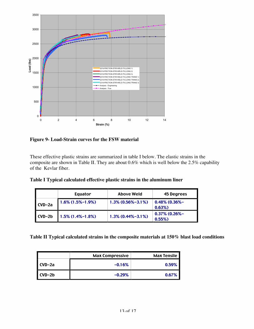
The dynamic pressure loading for the vessel was determined by the CALE2D code for thespecified weight of explosive. The pressure-time history was then transferred to a DYNA3D(three dimensional) model to begin the structural dynamic analysis. A three dimensional modelshown in Figure 8 was used to assess the asymmetries in the three piece end clamp design. Thespecial properties of the equatorial FSW weld region were included with properties based onexperimental tests as shown in Figure 9. The fiber composite properties were calculated using anew LLNL ply orientation formatter (POF) in conjunction with CADWIND software to generateinput for a new uni-directional elasto-plastic composite material model for this work. The newmaterial model created is number 62 in DYNA3D.
Figure 10 shows a typical structural response of the vessel at a 150% overloaded condition. Themost significant strain occurred near the equator of the aluminum liner. Instantaneous strainswere about 1.5% and the accumulated effective plastic strain (EPS) was about 1.7%. Thealuminum material had an average of 8% strain to uniaxial failure, but was found to suffer lowcycle fatigue after a few hundred cycles at 1 – 2 % strain.
13 of 17
Figure 9- Load-Strain curves for the FSW material
These effective plastic strains are summarized in table I below. The elastic strains in thecomposite are shown in Table II. They are about 0.6% which is well below the 2.5% capabilityof the Kevlar fiber.
Table I Typical calculated effective plastic strains in the aluminum liner
Equator Above Weld 45 Degrees
CVD-2a 1.6% (1.5%-1.9%) 1.3% (0.56%-3.1%) 0.48% (0.36%-0.63%)
CVD-2b 1.5% (1.4%-1.8%) 1.3% (0.44%-3.1%) 0.37% (0.26%-0.55%)
Table II Typical calculated strains in the composite materials at 150% blast load conditions
Max Compressive Max Tensile
CVD-2a -0.16% 0.59%
CVD-2b -0.29% 0.67%
Load vs. Strain Plots
0
500
1000
1500
2000
2500
3000
3500
0 2 4 6 8 10 12 14
Strain (%)
Lo
ad (
lbs)
2219-FRICTION-STIR-WELD-T6 (LONG 1)
2219-FRICTION-STIR-WELD-T6 (LONG 2)
2219-FRICTION-STIR-WELD-T6 (LONG 3)
2219-FRICTION-STIR-WELD-T6 (LONG TRANS 1)
2219-FRICTION-STIR-WELD-T6 (LONG TRANS 2)
2219-FRICTION-STIR-WELD-T6 (LONG TRANS 3)
Analysis - Engineering
Analysis - True

14 of 17
Figure 10. Typical structural response of the vessel showing strains in the aluminum linerto be about 1.5% and vibrations occurring with about a half millisecond period.
LEAKAGE CONSIDERATIONS
Transient leakage of hazardous materials such as uranium and beryllium particulates past theport seals needs to be prevented because of potential public and worker environmental hazards.Since no standard design codes exists for blast containment vessels of this type or purpose, wehave reviewed the guidance of related consensus codes. It was assumed that the detection of amicrogram of material would be sufficient for our development purposes and still be belowexisting standards.
Direct measurement of such small amount of particulate contaminants is difficult because theymay remain in the seal space or be unevenly distributed on the vessel surfaces. Instead, a gasleakage method is used in accordance with the ANSI N14.5 Code. A maximum U233particulate-to-aerosol concentration of 9 micrograms per cubic centimeter of gas released wasexperimentally determined by Curren and Bond in the 1980 paper “Leakage of RadioactivePowders from Containers” [2]. Since up to 9 micrograms could be released in 1 cc of gas, inorder to detect just 1 microgram, then the gas leakage sensitivity should be about 0.1 cc atstandard atmospheric conditions. A complete description of the Seal Monitoring System which

15 of 17
deals with any leakage of particulates and gases past the relatively soft O-ring seals at the vesselports is the focus of another paper given by Henning et.al. [1]..
EXPERIMENTAL RESULTSThe CVD2a vessel was instrumented with an array of strain gages and temperature sensorsbonded to the vessel. Static and dynamic pressure transducers were mounted inside the vesselequator and attached to the top plug. The vessel and associated sensors were grounded andshielded to a single point to minimize the electrical noise generated by the ionized gas blastfront. This method electrically floated the instrumentation, the sensor cable shields, and sensors.A preliminary 5% explosive shot was used to check out the instrumentation system.
Figure 11. CVD-2a half scale Kevlar composite vessel in test stand
The CVD –2a vessel as seen in Figure 11, was then tested to 150% of the blast load andproduced a peak blast pressure of 280Mpa (40 KSI). The vessel withstood the blast withoutdamage. No damage to the welds or composite could be found.
To diagnose the leakage past the O-ring seals, small capillary tubes were monitored from eachO-ring gap. Initially, this space was filled with pure nitrogen gas, while the full vessel was filled

16 of 17
with a mixture of 10% Argon, 20% Oxygen, and 70% nitrogen. After the blast, the second O-ring space had some argon, carbon monoxide and hydrocarbons present. However, the other O-rings did not appear to leak. While there was a small amount of oxygen and argon in thesespaces, there was no carbon monoxide or hydrocarbons present from the blast. The small amountof argon could be an experimental error or possibly be caused by an inward air leak as theflanges vibrated after the blast.
Following the blast tests, the vessel was carefully taken apart to look for signs of leakage. Novisible external leakage was found, but there were some dark areas on the port surfaces wherethe steel plugs rubbed against the aluminum ports because of vessel vibrations during the blast.There were no signs of blast combustion products beyond the first two seals as seen in Figure 12.
Figure 12. The top plug with sampling portsbetween the O-rings and evidence of particulateleakage past the first and second seals from thebottom.
CONCLUSIONS
After several years of development it now appears possible to utilize filament wound blastcontainment vessels that are light in weight and optically thin to X-rays or protons. Redundantport seals are used to meet strict environmental and safety standards comparable to those used

17 of 17
for nuclear material shipping containers. These same composite design technologies can beapplied to other containment vessels and to personnel shields subject to blast conditions.
REFERENCES
1) Henning et al., Seal Monitoring System for an Explosive Containment Vessel, imbid.2) Grundler, Test Procedure for O-ring Interspatial Volume Test on CVD-2, LLNL report
ERD03-167-AA (Nov. 11, 2003)3) Hathcoat et, al, Empirical Measurements from the CVD-2a Test Series, LLNL Report
ERD04-535-AA4) Kokko, Edwin, Results 111402, LLNL Internal Presentation5) Hagler, Lisle, Gauges1, Sept 24, 2003, LLNL Internal Presentation