composite structure (31-38).pdf
TRANSCRIPT
160
Lecture Note – 31
Introduction to Steel-Concrete Composite Building Code: IS 11384-1985: Code of Practice for Composite Construction in Structural Steel and Concrete Concept of Tall Building Design From a structural engineer's point of view tall building or multi-storeyed building is one that, by virtue of its height, is affected by lateral forces to an extent that they play an important role in the structural design Multi-storeyed buildings provide a large floor area in a relatively small area of land in urban centres. Advantages of Steel Tall Buildings • Faster to erect • Lighter • Better quality control • Reduced site time - Fast track Construction • Large column free space and amenable for alteration • Less material handling at site • Less percentage of floor area occupied by structural elements • Has better ductility and hence superior lateral load behavior; better earthquake
resistance Anatomy
• Beams • Columns • Floors • Bracing Systems • Connections
161
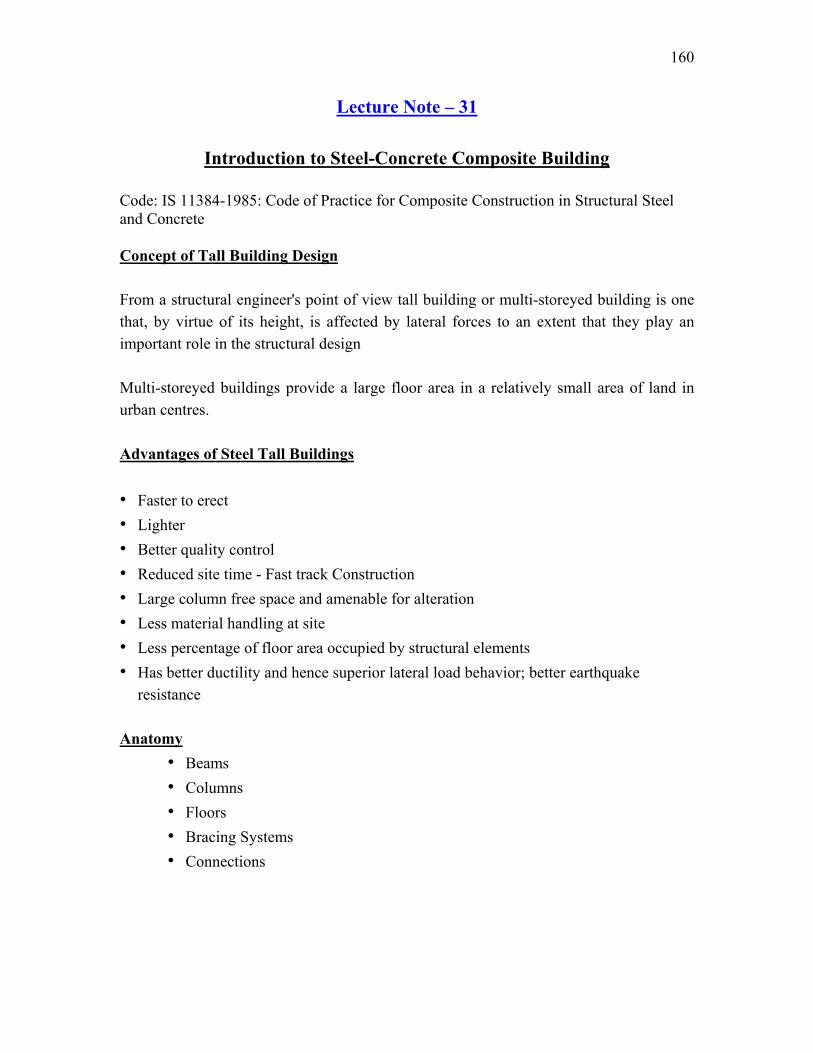
Beam and Column Construction Common types of floor systems • Concrete slabs supported by open-web joists • One-way and two-way reinforced concrete slabs supported on steel beams • Concrete slab and steel beam composite floors • Composite profiled decking floors • Precast concrete floors on steel beams
Concrete slabs supported by open-web joists
Bottom chord
Concrete slab
Tack weld
Stud welding
Open web joist
Beam
One-way slab
Column

162
One-way and two-way reinforced concrete slabs supported on steel beams
Concrete slab and steel beam composite floors
Steel beam encased in concrete (Rarely used nowadays)
Steel beam acting composite with concrete slab using shear connectors
Welded wire mesh for effectively bondingfireproofing concrete.
163
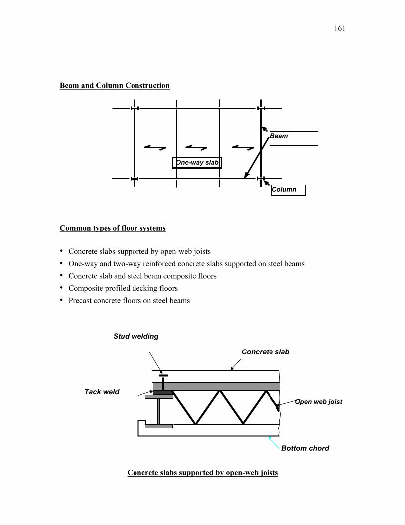
Profiled decking floors • Popular for lighter loads • Advantages:
– Do not need form work – Lightweight concrete is used resulting in reduced dead weight – Decking distributes shrinkage strains, thus prevents serious cracking – Decking stabilises the beam against lateral buckling, until the concrete hardens – Cells in decking are convenient for locating services
Profiled decking floors
Precast concrete slab floors
Section A-A showing dimples
A
A
Profiled sheet
164
Lecture Note – 32
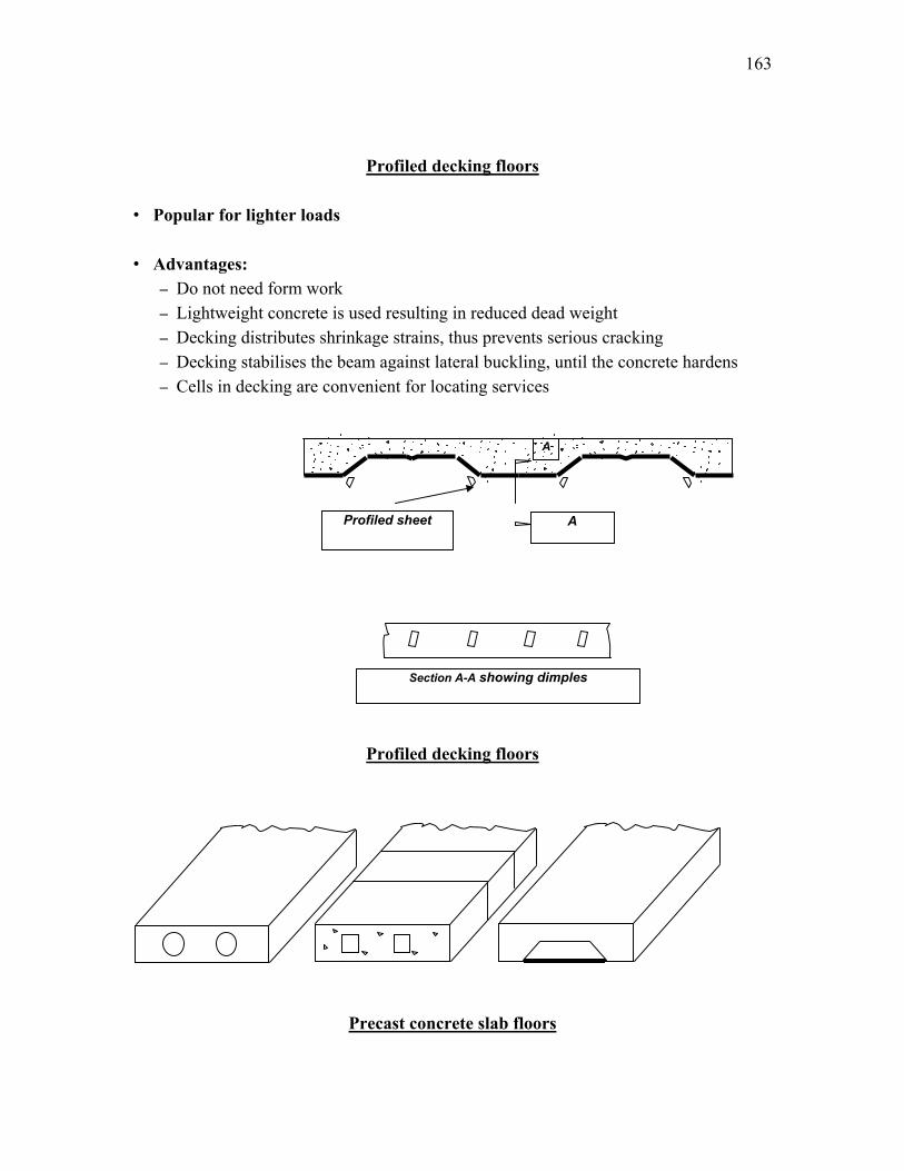
Steel-concrete composite construction A composite member is defined as consisting of a rolled or a built-up structural steel shape that is either filled with concrete, encased by reinforced concrete or structurally connected to a reinforced concrete slab. Composite members are constructed such that the structural steel shape and the concrete act together to resist axial compression and /or bending.
Advantages: Advantageous properties of both steel and concrete are effectively utilized in a composite structure. For a typical three (3) to ten (10) storied structure, time of construction of the complete structure reduces by about 25 percent. The advantages can be fully utilized as summarized below:
1. Faster construction for maximum utilization of rolled and/or fabricated components (structural steel members) and hence quick return of the invested capital.
165
2. Advantages based on life-cycle-cost analysis instead of initial cost only. 3. Quality assurance of the steel material along with availability of proper paint
system suiting to different corrosive environment. 4. Ability to cover large column free area in buildings and longer span for
bridges/flyovers. This leads to more usable space. 5. Reinforced cement concrete (RCC) slab is in compression and steel joist is in
tension. Hence, most effective utilization of the materials can be achieved. 6. Better seismic resistance i.e. best suited to resist repeated earthquake loadings,
which require a high amount of ductility and hysteretic energy of the material/structural frame.
7. Composite sections have higher stiffness than the corresponding steel sections (in a steel structure) and thus bending stress as well as deflection are lesser.
8. Keeping span and loading unaltered, a lower structural steel section (having lesser depth and weight) can be provided in composite construction, compared to the section required for non-composite construction.
9. Reduced beam depth reduces the story height and consequently the cost of cladding in a building and lowers the cost of embankment in a flyover (due to lower height of embankment).
10. Reduced depth allows provision of lower cost for fire proofing of beam’s exposed faces.
11. Cost of formwork is lower compared to RCC construction. 12. Cost of handling and transportation is minimized for using major part of the
structure fabricated in the workshop. 13. Easy structural repair/modification/maintenance. 14. Structural steel component has considerable scrap value at the end of useful life. 15. Reductions in overall weight of structure and thereby reduction in foundation
costs. 16. More use of a material i.e. steel, which is durable, fully recyclable on replacement
and environment friendly. Composite Beams: Slab and beam type constructions are commonly used in bridges and buildings. Slab-beam interaction is possible through the use of shear connector welded at the top of the flanges. This behaves like a T-beam with the slab or part of it acting as a flange in compression. Further, bond between the shear connector and slab is assumed to be perfect, i.e., no slippage between the top flange of the steel beam and slab is permitted. For determining section properties, it is convenient to transform the concrete slab into an
166
equivalent steel section by dividing concrete area by modular ratio. The rest of the analysis is carried out as if the section were made of a homogeneous material. In conventional composite construction, concrete slabs rest over steel beams and are supported by them. Under load these two components act independently and a relative slip occurs at the interface if there is no connection between them. With the help of a deliberate and appropriate connection provided between the beam and the concrete slab, the slip between them can be eliminated. In this case the steel beam and the slab act as a “composite beam” and their action is similar to that of a monolithic T- beam. Concrete is stronger in compression than in tension, and steel is susceptible to buckling in compression. By the composite action between the two, we can utilize their respective advantages to the fullest extent. Generally, in steel-concrete composite beams, steel beams are integrally connected to prefabricated or cast-in-situ reinforced concrete slabs. There are many advantages associated with steel concrete composite construction. Some of these are listed below. Advantages of Construction:
• The most effective utilization of steel and concrete is achieved.
• Keeping the span and loading unaltered, a more economical steel section (in terms of depth and weight) is adequate in composite construction compared with conventional non-composite construction.
• As the depth of beam reduces, the construction depth reduces, resulting in enhanced headroom.
• Because of its larger stiffness, composite beams have less deflection than steel beams.
• Composite construction is amenable to “fast-tract” construction because of using rolled steel and pre-fabricated components, rather than cast-in-situ concrete.
• Encased steel beam sections have improved fire resistance and corrosion. Disadvantages:
1. Additional costs for shear connectors and their installation. For lightly loaded short beams, this extra cost may exceed the cost-reduction on all accounts.
Methods of Composite Construction of Beams Two methods of composite construction: Shored and Un-shored.
167
The concrete slab is usually cast after the steel beams are erected. The two methods of construction differ in the manner of supporting the formwork with fresh concrete and other construction loads. In shored method, the weight of formwork and fresh concrete is supported by a separate system of shores and steel beams carry their own weight only. When the concrete attains at least 75% of its 28-days strength, the shores are removed and then all loads including weight of concrete and live loads are carried by the composite action of steel and concrete. Thus in shored construction, as almost the entire load is carried by composite action, it is possible to use a lighter steel beam. In un-shored construction, no shores are used and the weight of the formwork, fresh concrete and steel beam and other construction loads are all carried by the steel beam alone. When the concrete attains at least 75% of its ultimate strength, the formwork is removed and all subsequent loads including the live loads are carried by the composite action. Thus in un- shored construction a relatively heavier steel beams is required. In shored method though there is some saving in steel, but there is extra cost of shoring. In practice, the ultimate economy in shored method is negligible or may be even negative. So it is preferable to use heavier steel beam and do away with shoring. The un-shored method is preferable for the following reasons:
• The trouble due to probable settlement of shoring is avoided in un-shored construction.
• The ultimate strength of composite beam with heavier steel section is higher. Thus with practically the same cost, higher safety margin is obtained in un-shored construction.
168
Lecture Note – 33
Design of Composite Beam & Column Codal provisions of IS 11384-1985 IS 11384-1985 i.e. Code of Practice for Composite Construction in Structural Steel and Concrete is restricted to buildings only. It stipulates that the steel-concrete composite structures may be designed by the limit state method. As per IS 11384-1985, a composite structure or part of it, is considered, unfit for use when it exceeds the limit state, beyond which it infringes one of the criteria governing its performance or use. The limit states can be classified into the following categories: • Ultimate Limite State – which corresponds to the maximum load carrying capacity. • Serviceability Limit State - which are related to the criteria governing normal use and
durability. Ultimate Limit State to be considered in buildings and structures made of steel-concrete composite construction are:
• Collapse due to flexural failure of one or more critical sections,
• Collapse due to horizontal shear failure at the interface between the steel beam and the concrete slab,
• Collapse due to vertical separation of the concrete slab from the steel beam The serviceability limit states to be considered are as follows: • Limit state of deflection, and • Limit state of stresses in concrete and steel Design for the limit state of collapse in flexure is based on the following assumptions • Plane sections normal to the axis remain plane-after bending. • The maximum bending strain in concrete at the outermost compression fiber is
taken as 0.0035.
169
• For characteristic compressive strength of concrete fck , maximum permissible bending compression in the structure is assumed to be 0.67 fck. With a value of 1.5 for the partial safety factor for the strength of concrete material, maximum design stress is 0.446 fck.
• The tensile strength of concrete is ignored; • The stress-strain curve for the steel section is assumed to be bilinear and partial
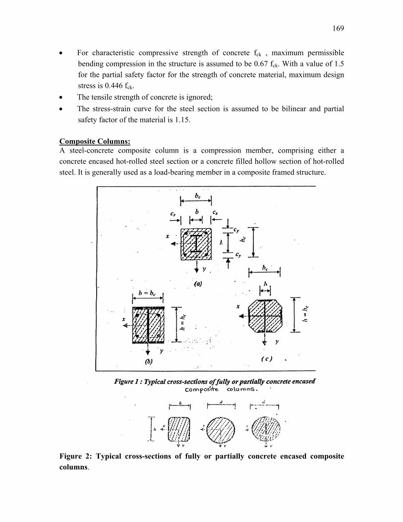
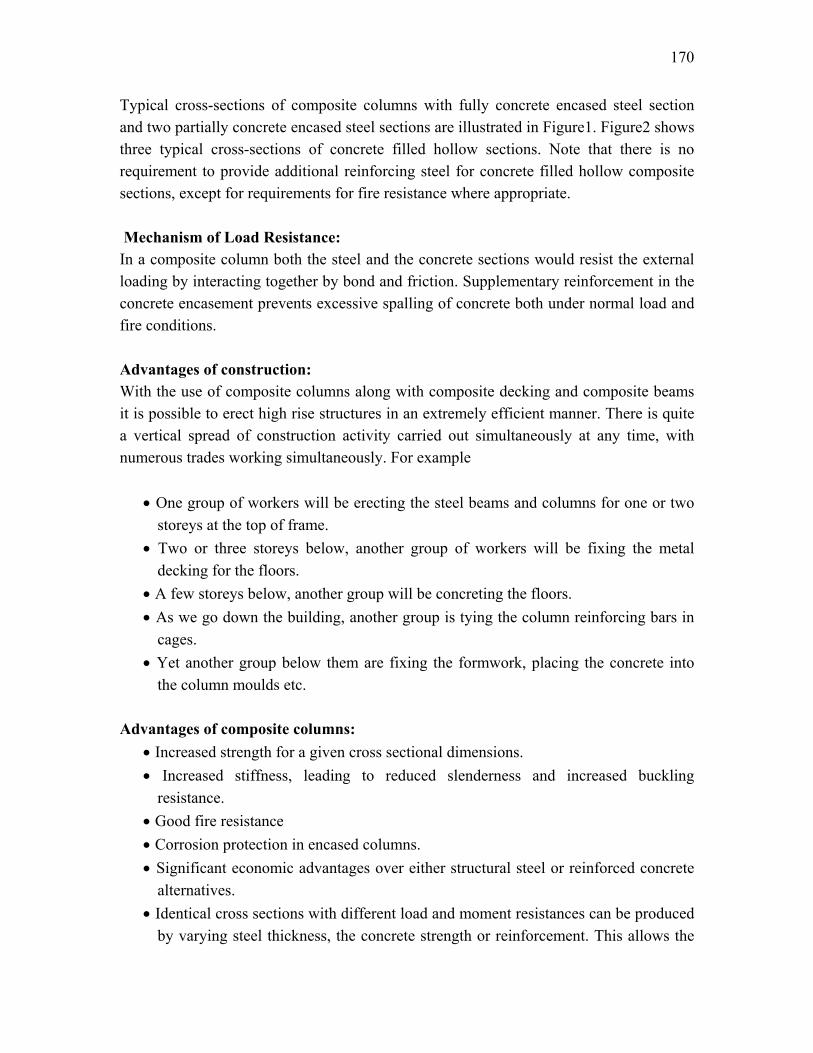
safety factor of the material is 1.15. Composite Columns: A steel-concrete composite column is a compression member, comprising either a concrete encased hot-rolled steel section or a concrete filled hollow section of hot-rolled steel. It is generally used as a load-bearing member in a composite framed structure. Figurcolum
e 2: Typical cross-sections of fully or partially concrete encased composite ns.
170
Typical cross-sections of composite columns with fully concrete encased steel section and two partially concrete encased steel sections are illustrated in Figure1. Figure2 shows three typical cross-sections of concrete filled hollow sections. Note that there is no requirement to provide additional reinforcing steel for concrete filled hollow composite sections, except for requirements for fire resistance where appropriate. Mechanism of Load Resistance: In a composite column both the steel and the concrete sections would resist the external loading by interacting together by bond and friction. Supplementary reinforcement in the concrete encasement prevents excessive spalling of concrete both under normal load and fire conditions. Advantages of construction: With the use of composite columns along with composite decking and composite beams it is possible to erect high rise structures in an extremely efficient manner. There is quite a vertical spread of construction activity carried out simultaneously at any time, with numerous trades working simultaneously. For example • One group of workers will be erecting the steel beams and columns for one or two
storeys at the top of frame. • Two or three storeys below, another group of workers will be fixing the metal
decking for the floors. • A few storeys below, another group will be concreting the floors. • As we go down the building, another group is tying the column reinforcing bars in
cages. • Yet another group below them are fixing the formwork, placing the concrete into
the column moulds etc. Advantages of composite columns: • Increased strength for a given cross sectional dimensions. • Increased stiffness, leading to reduced slenderness and increased buckling
resistance. • Good fire resistance • Corrosion protection in encased columns. • Significant economic advantages over either structural steel or reinforced concrete
alternatives. • Identical cross sections with different load and moment resistances can be produced
by varying steel thickness, the concrete strength or reinforcement. This allows the
171
outer dimensions of a column to be held constant over a number of floors in a building, thus simplifying the construction and architectural detailing.
• Erection of high rise building in an extremely efficient manner. • Formwork is not required for concrete filled tubular sections.
172
Lecture Note – 34
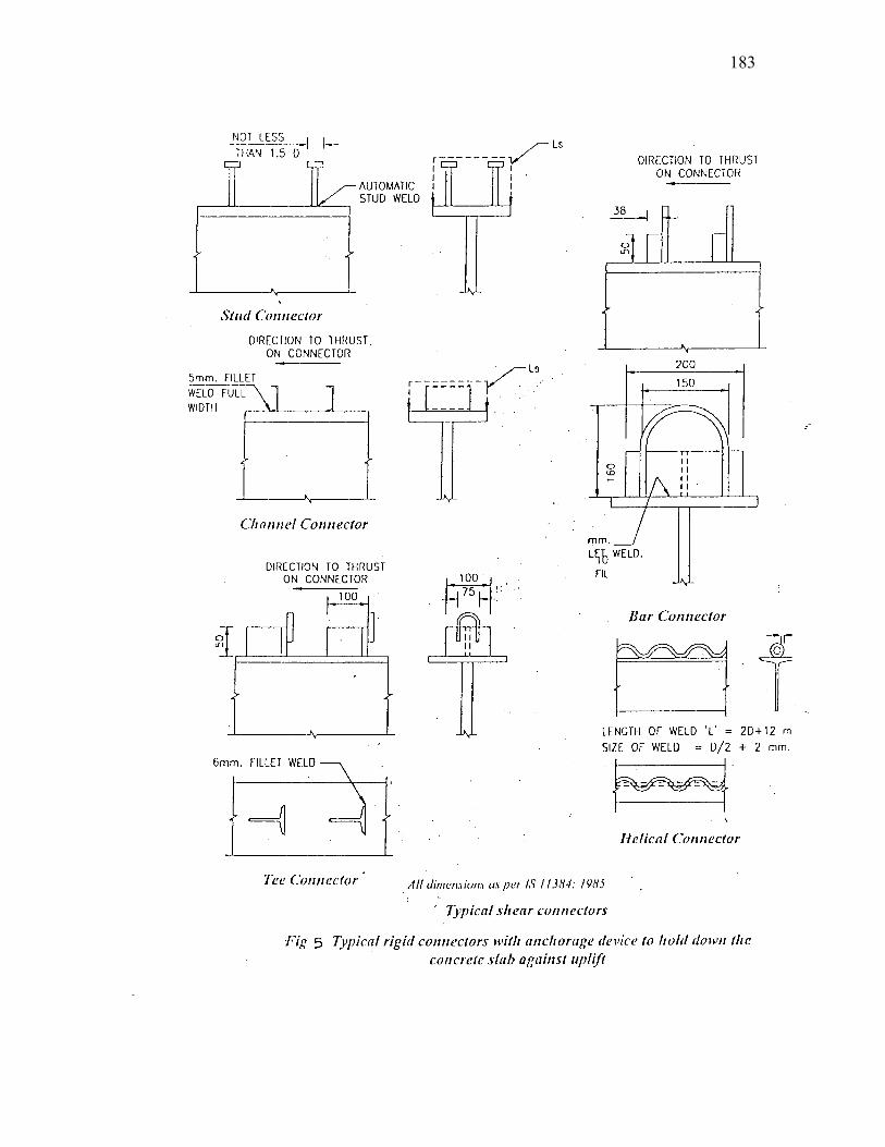
Shear Connector Composite construction consists of providing monolithic action between prefabricated units like steel beams or pre-cast reinforced concrete or pre-stressed concrete beams and cast-in-situ concrete, so that the two will act as one unit. Although there is bound to be a certain amount of natural bond between concrete and steel at least at the initial stages, this bond cannot be relied upon as the same is likely to be deteriorate due to use and over load. Mechanical shear connectors are therefore provided to help the steel and concrete element to act in a composite manner ignoring the contribution made by the inherent natural bond towards this effect. Primarily shear connectors are intended to resist the horizontal movement between the concrete slab and the steel beam and to transmit the horizontal shear between the two. Shear Connectors are also called upon to prevent vertical separation of the slab from the steel girder at the contact surface. Therefore, shear connectors are to be designed to cater for integral action of the composite structure at all load conditions on the following basis: a) Transmission of longitudinal shear along the contact surface without slip. b) Prevention of vertical separation of the in-situ RC slab from the pre-fabricated
structural beam. Types of Shear Connectors Shear connectors are generally classified into three categories, viz.
a) Rigid type b) Flexible type c) Bond type
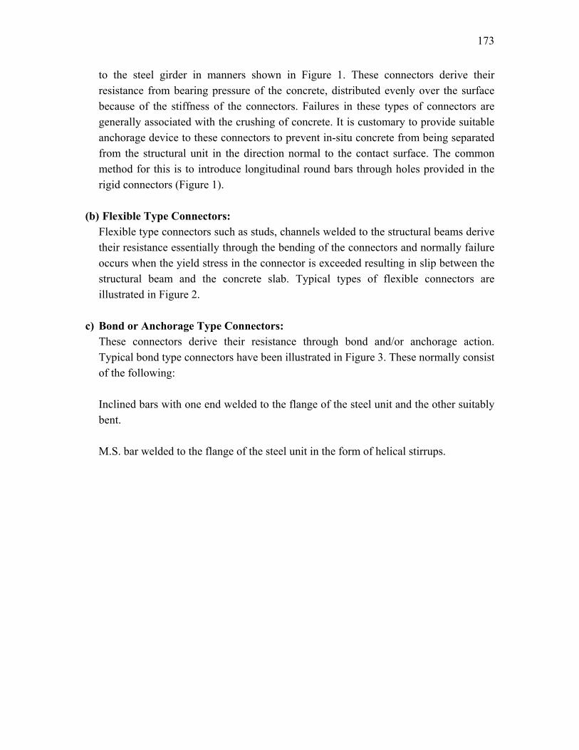
The basic characteristic of the above connectors are discussed below: (a) Rigid Type Connectors: These connectors as the name implies, are designed to be bent proof with little
inherent power of deformation. These types of shear connectors could be of various shapes, but the most common types are short length of bars, angles or tees welded on
173
to the steel girder in manners shown in Figure 1. These connectors derive their resistance from bearing pressure of the concrete, distributed evenly over the surface because of the stiffness of the connectors. Failures in these types of connectors are generally associated with the crushing of concrete. It is customary to provide suitable anchorage device to these connectors to prevent in-situ concrete from being separated from the structural unit in the direction normal to the contact surface. The common method for this is to introduce longitudinal round bars through holes provided in the rigid connectors (Figure 1).
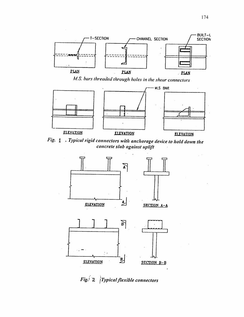
(b) Flexible Type Connectors: Flexible type connectors such as studs, channels welded to the structural beams derive
their resistance essentially through the bending of the connectors and normally failure occurs when the yield stress in the connector is exceeded resulting in slip between the structural beam and the concrete slab. Typical types of flexible connectors are illustrated in Figure 2.
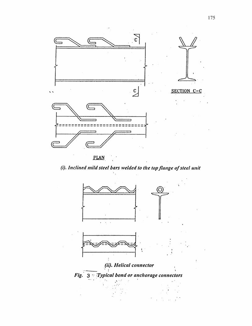
c) Bond or Anchorage Type Connectors: These connectors derive their resistance through bond and/or anchorage action.
Typical bond type connectors have been illustrated in Figure 3. These normally consist of the following:
Inclined bars with one end welded to the flange of the steel unit and the other suitably
bent. M.S. bar welded to the flange of the steel unit in the form of helical stirrups.
174
175
176
Design Strength of Shear Connectors: Relevant codes: In India, primarily two codes of practices are in use for composite construction in structural steel and concrete. These are: I.R.C.22-1986: Standard specifications and code of practice for road bridges, The Indian Road Congress, Delhi. I.S.11384-1985: Code of practice for composite construction in structural steel and concrete, Bureau of India Standards, New Delhi. While IRC: 22-1986 is based on working stress method of design and is applicable to road bridges, IS:11384-1985 is based on limit state design method, and its use has been restricted to buildings only. It is proposed to discuss in the following paragraphs the methods recommended by these codes for calculating design strength of shear connectors: Shear Connectors as per IRC:22-1986 Shear connectors may be either mild steel or high tensile steel according to the material specification of the steel beam. As mild steel beams are commonly used as construction material in India, design methodology of mild steel shear connectors is being discussed in the following sections. Shear capacity Shear capacity of a shear connector may be calculated as follows: (a) For welded channel/angle/tee connector made of mild steel with minimum ultimate
strength of 420 to 500 MPa, yield point of 230 MPa and elongation 21%. ( )3.32 0.5 ckQ h t Lf= +
Where,
Q = The safe shear resistance in Newton of one shear connector
h = The maximum thickness of flange measured at the web in mm
t = Thickness of the web of shear connector in mm
fck = Characteristics compressive strength of concrete
177
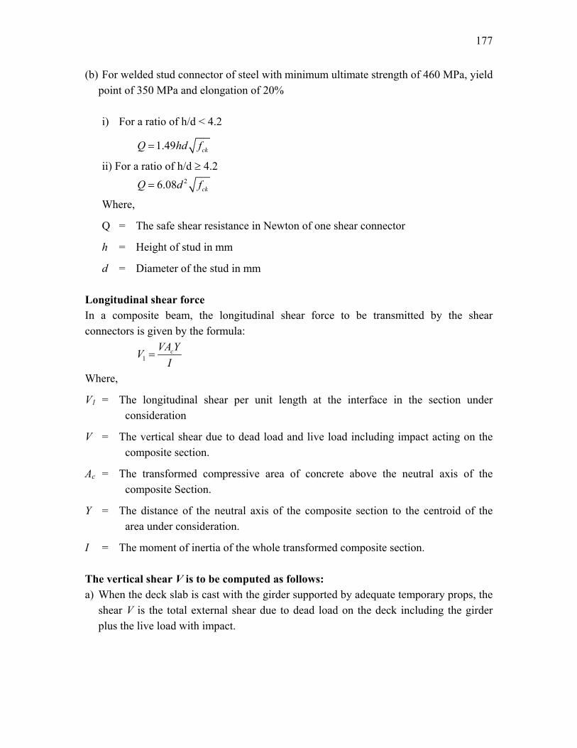
(b) For welded stud connector of steel with minimum ultimate strength of 460 MPa, yield point of 350 MPa and elongation of 20%
i) For a ratio of h/d < 4.2
1.49 ckQ hd f=
ii) For a ratio of h/d ≥ 4.2 26.08 ckQ d f=
Where,
Q = The safe shear resistance in Newton of one shear connector
h = Height of stud in mm
d = Diameter of the stud in mm Longitudinal shear force In a composite beam, the longitudinal shear force to be transmitted by the shear connectors is given by the formula:
1cVA YV
I=
Where,
V1 = The longitudinal shear per unit length at the interface in the section under consideration
V = The vertical shear due to dead load and live load including impact acting on the composite section.
Ac = The transformed compressive area of concrete above the neutral axis of the composite Section.
Y = The distance of the neutral axis of the composite section to the centroid of the area under consideration.
I = The moment of inertia of the whole transformed composite section. The vertical shear V is to be computed as follows: a) When the deck slab is cast with the girder supported by adequate temporary props, the
shear V is the total external shear due to dead load on the deck including the girder plus the live load with impact.
178
b) When the deck slab is cast with the girder un-propped, the shear V will be the total external shear due to load added after the concrete has attained a strength compatible to the composite action assumed plus the live load with impact.
c) In case (b), when the slab is supported independent of the girder system, the shear V
will be the total external shear including the self-weight of the slab. Spacing of shear connectors i) Shear connectors are to be provided throughout the length of the beam and may be
uniformly spaced between critical cross sections. ii) Spacing of the shear connectors shall be determined from the formula
1
QpV
= ∑
Where, p = Pitch of shear connectors
V1 = The longitudinal shear per unit length at the interface in the section under consideration
Q = Safe shear resistance of each shear connector as computed in earlier section.
∑Q = The total shear resistance of all connectors at one transverse cross section of the girder iii) The maximum spacing of the shear connectors in the longitudinal direction shall be
limited to: (a) 600 mm or (b) thee times the thickness of the slab or (c) four times the height of the connector
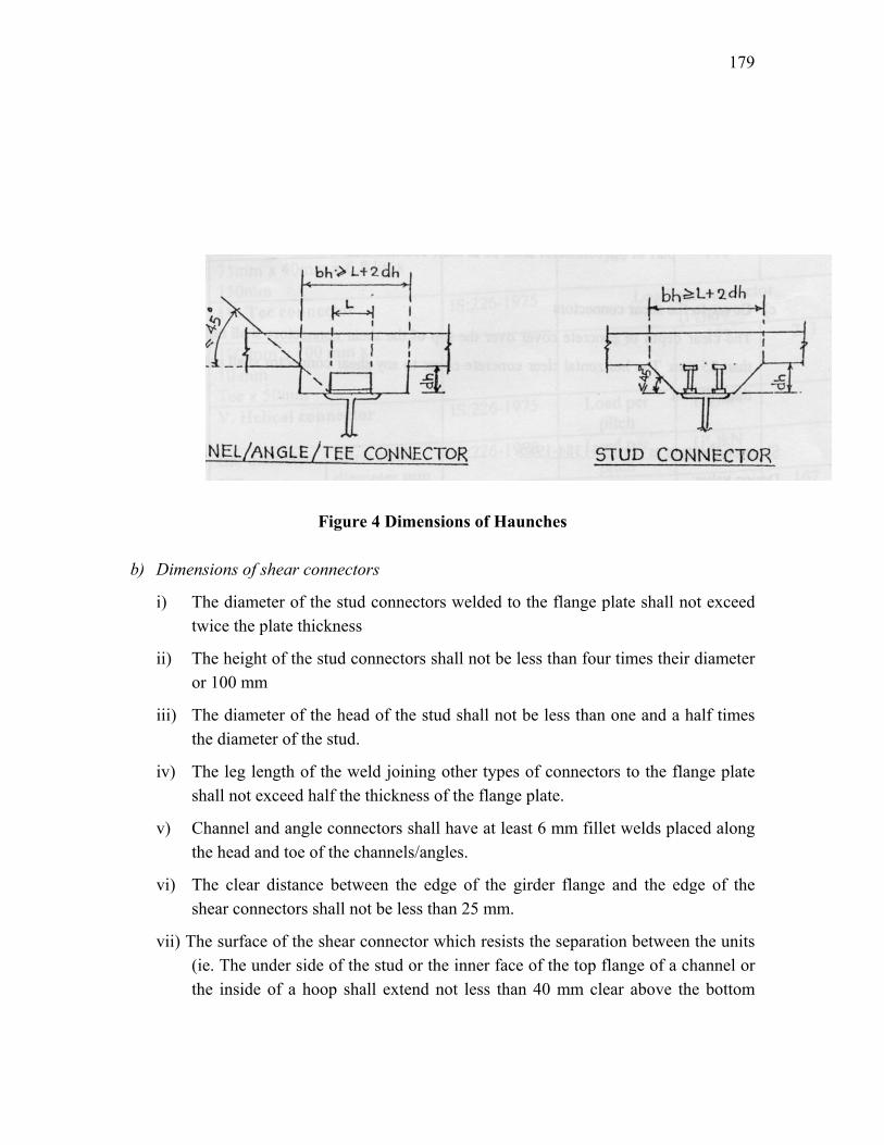
Whichever is the least. iv) The spacing of the stud connectors in any direction shall not be less than 75 mm. Detailing a) Dimensions of haunches The dimensions for the haunches to be provided between top of the stud and soffit of
slab shall be as indicated in Figure 4, the sides of the haunches being located outside at the line drawn at 45 degrees from the outside edge of the base of the connector.
179
b
Figure 4 Dimensions of Haunches
) Dimensions of shear connectors
i) The diameter of the stud connectors welded to the flange plate shall not exceed twice the plate thickness
ii) The height of the stud connectors shall not be less than four times their diameter or 100 mm
iii) The diameter of the head of the stud shall not be less than one and a half times the diameter of the stud.
iv) The leg length of the weld joining other types of connectors to the flange plate shall not exceed half the thickness of the flange plate.
v) Channel and angle connectors shall have at least 6 mm fillet welds placed along the head and toe of the channels/angles.
vi) The clear distance between the edge of the girder flange and the edge of the shear connectors shall not be less than 25 mm.
vii) The surface of the shear connector which resists the separation between the units (ie. The under side of the stud or the inner face of the top flange of a channel or the inside of a hoop shall extend not less than 40 mm clear above the bottom
180
transverse reinforcement, nor less than 40 mm into compression zone of the concrete flange.
viii) Where a concrete haunch is used between the steel flange and the soffit of the slab, the surface of the connector that resists separation between the two units shall be placed not less than 40 mm above the transverse reinforcement in the haunches.
ix) The overall height of the connector including any hoop which is an integral part of the connector shall be at least 100 mm with a clear cover of 25 mm.
c) Cover to the shear connectors The clear depth of concrete cover over the top of the shear connectors shall not be less
than 25 mm. The horizontal clear concrete cover to any shear connector shall not be less than 50mm.
181
Lecture Note – 35
Shear Strength
Design value: Design values for a range of commonly used types of connectors are illustrated in Table –1. These design values are taken as 67% of the ultimate capacity. Number of connectors: The number of connectors should be calculated to resist the maximum value of the total shear force to be transmitted at collapse between points of maximum and zero moment. This force is taken as the force in concrete at ultimate moment and is given by 0.36cc ck uF f bX=
This acts at a depth of 0.42Xu with the value restricted to maximum of d. Here,
fck = Characteristic strength of concrete b = Breadth of flange in T-section Xu = Depth of neutral axis at ultimate limit state of flexure d = Thickness of concrete section
Haunch in concrete Design values of the connectors in Table-1 are not valid where there is a concrete haunch with a slope steeper than 1 vertical to 3 horizontal between the top flange of the steel beam and the under side of the concrete slab. In such cases value of shear connector has to be based on actual shear tests of the proposed haunch and reinforcement. Spacing of connectors
a) The number of connectors as determined above may normally be uniformly spaced between each end of beam and the section of maximum moment.
b) Spacing of connectors should not be greater than four times the slab thickness
nor greater than 600 mm.
182
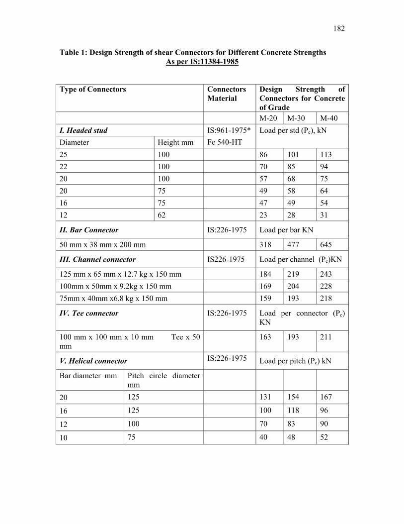
Table 1: Design Strength of shear Connectors for Different Concrete Strengths As per IS:11384-1985
Type of Connectors Connectors
Material Design Strength of Connectors for Concrete of Grade
M-20 M-30 M-40 I. Headed stud Diameter Height mm
IS:961-1975* Fe 540-HT
Load per std (Pc), kN
25 100 86 101 113 22 100 70 85 94 20 100 57 68 75 20 75 49 58 64 16 75 47 49 54 12 62 23 28 31
II. Bar Connector IS:226-1975 Load per bar KN
50 mm x 38 mm x 200 mm 318 477 645
III. Channel connector IS226-1975 Load per channel (Pc)KN
125 mm x 65 mm x 12.7 kg x 150 mm 184 219 243 100mm x 50mm x 9.2kg x 150 mm 169 204 228 75mm x 40mm x6.8 kg x 150 mm 159 193 218
IV. Tee connector IS:226-1975 Load per connector (Pc) KN
100 mm x 100 mm x 10 mm Tee x 50 mm
163 193 211
V. Helical connector IS:226-1975 Load per pitch (Pc) kN
Bar diameter mm Pitch circle diameter mm
20 125 131 154 167
16 125 100 118 96
12 100 70 83 90
10 75 40 48 52
183
184
Detailing a) The distance between the edge of the connector and the edge of the flange to which
it is connected shall not be less than 25 mm. b) The overall height of the connector, i.e., the length of the stud, diameter of the
helix, height of channel, hoop etc., should not be less than 50 mm nor less than 25 mm into the compression zone of the concrete slab.
c) The diameter of the head of the stud should not be less than 1.5 times the diameter
of the stud and the thickness of the head shall not be less than 0.4 times the shank diameter.
185
Lecture Note – 36
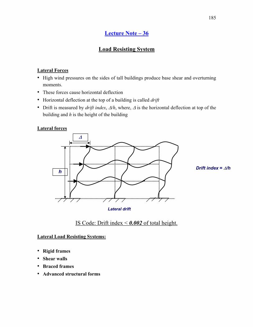
Load Resisting System Lateral Forces • High wind pressures on the sides of tall buildings produce base shear and overturning
moments. • These forces cause horizontal deflection • Horizontal deflection at the top of a building is called drift • Drift is measured by drift index, ∆/h, where, ∆ is the horizontal deflection at top of the
building and h is the height of the building Lateral forces Lateral Load Resisting Systems: • Rigid frames • Shear walls • Braced frames • Advanced structural forms
Lateral drift
∆
h Drift index = ∆/h
IS Code: Drift index < 0.002 of total height.
186
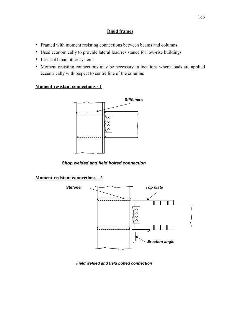
Rigid frames • Framed with moment resisting connections between beams and columns. • Used economically to provide lateral load resistance for low-rise buildings • Less stiff than other systems • Moment resisting connections may be necessary in locations where loads are applied
eccentrically with respect to centre line of the columns Moment resistant connections - 1
Moment resistant connections – 2
Shop welded and field bolted connection
Stiffeners
Top plate Stiffener
Field welded and field bolted connection
Erection angle
187
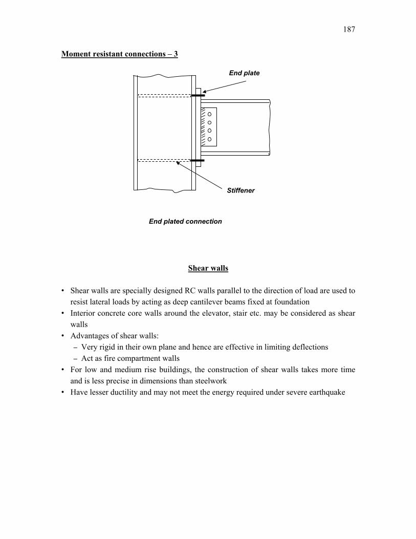
Moment resistant connections – 3
Shear walls • Shear walls are specially designed RC walls parallel to the direction of load are used to
resist lateral loads by acting as deep cantilever beams fixed at foundation • Interior concrete core walls around the elevator, stair etc. may be considered as shear
walls • Advantages of shear walls:
– Very rigid in their own plane and hence are effective in limiting deflections – Act as fire compartment walls
• For low and medium rise buildings, the construction of shear walls takes more time and is less precise in dimensions than steelwork
• Have lesser ductility and may not meet the energy required under severe earthquake
End plate
End plated connection
Stiffener
188
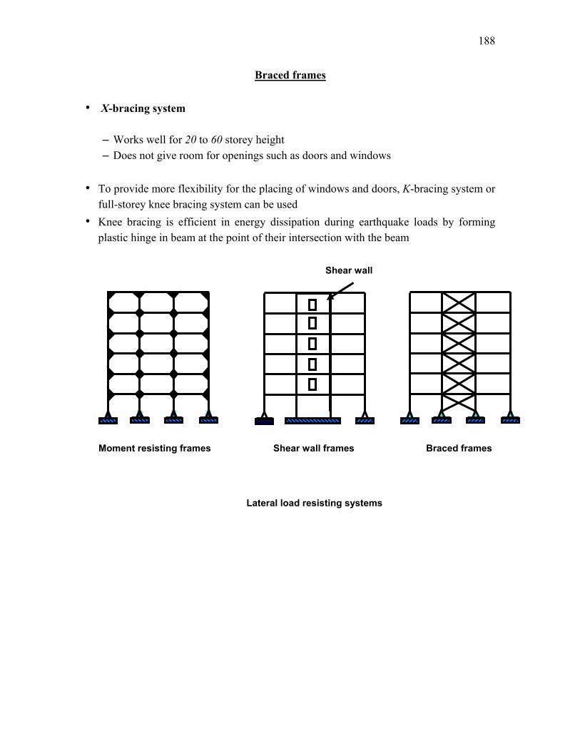
Braced frames • X-bracing system
– Works well for 20 to 60 storey height – Does not give room for openings such as doors and windows
• To provide more flexibility for the placing of windows and doors, K-bracing system or
full-storey knee bracing system can be used • Knee bracing is efficient in energy dissipation during earthquake loads by forming
plastic hinge in beam at the point of their intersection with the beam
Moment resisting frames
Lateral load resisting systems
Braced frames Shear wall frames
Shear wall
189
Lecture Note – 37
Connections Depending upon structural behaviour, connections are classified as: • Simple connections
– Detailed to allow beam end to rotate freely and beam behaves as a simply supported beam
– Transfers shear and axial forces between connecting members but does not transfer bending moment
• Rigid connections – Detailed to ensure a monolithic joint such that angle between beam and column
before deformation remains same even after deformation – Transfers shear, axial force and bending moment from beam to column
• Semi-rigid connections – Designed to transmit full shear force and a fraction of the rigid joint bending
moment across the joint – Analysis of frames with such joints is complex
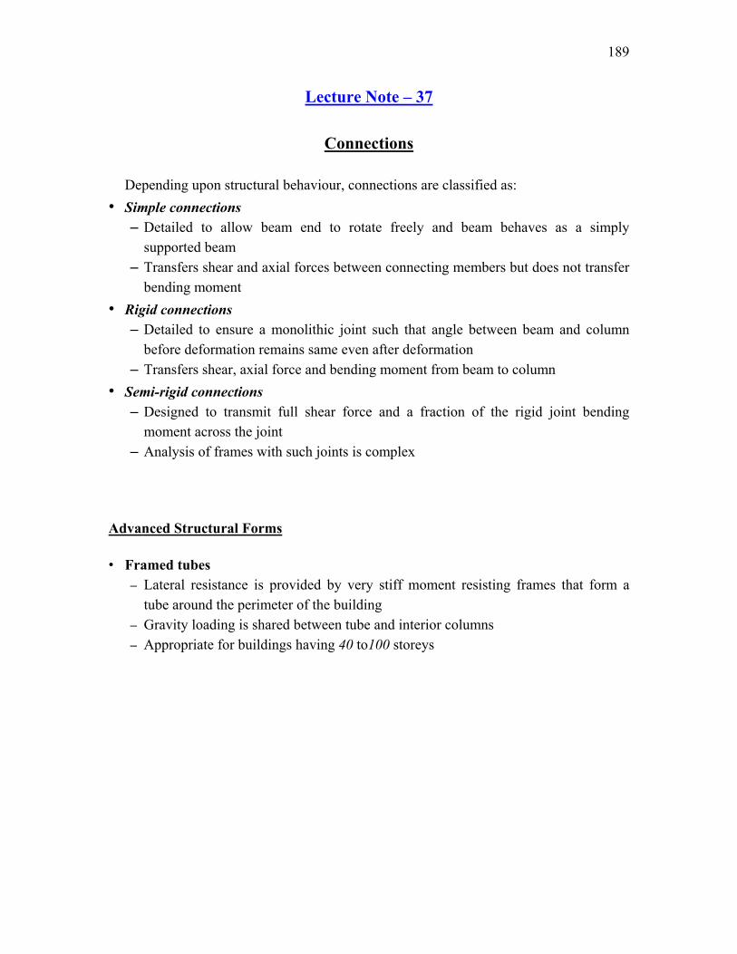
Advanced Structural Forms • Framed tubes
– Lateral resistance is provided by very stiff moment resisting frames that form a tube around the perimeter of the building
– Gravity loading is shared between tube and interior columns – Appropriate for buildings having 40 to100 storeys
190
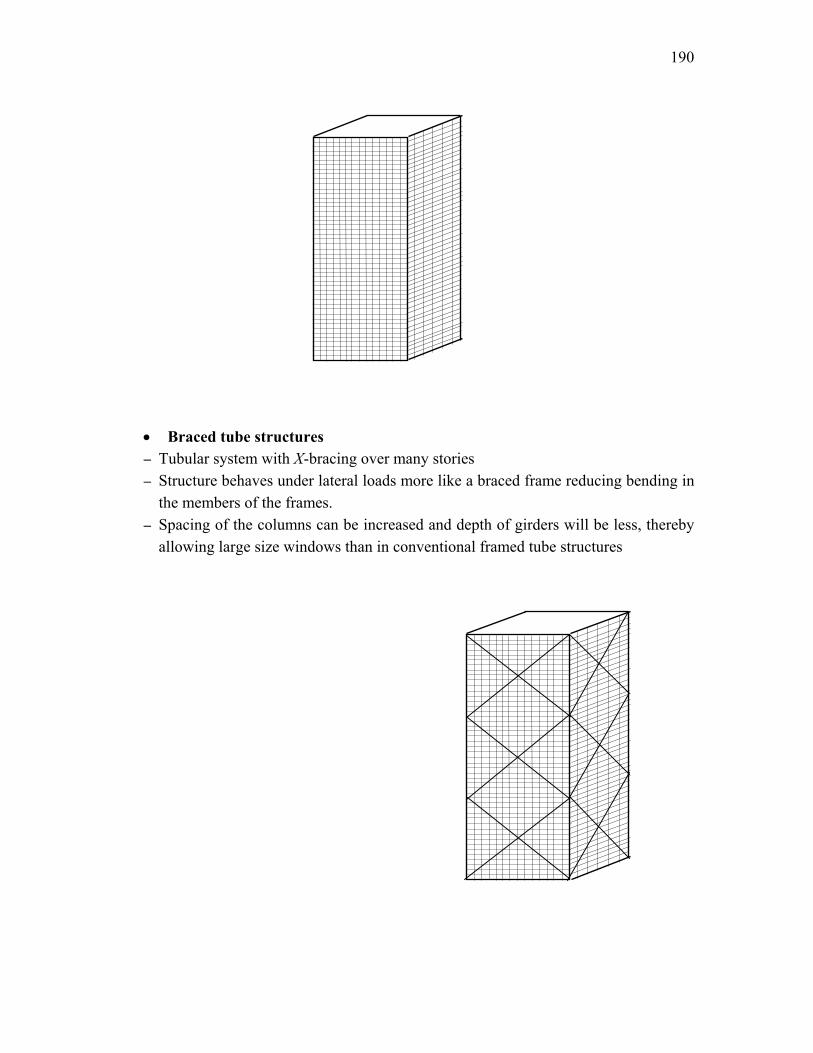
• Braced tube structures – Tubular system with X-bracing over many stories – Structure behaves under lateral loads more like a braced frame reducing bending in
the members of the frames. – Spacing of the columns can be increased and depth of girders will be less, thereby
allowing large size windows than in conventional framed tube structures
191
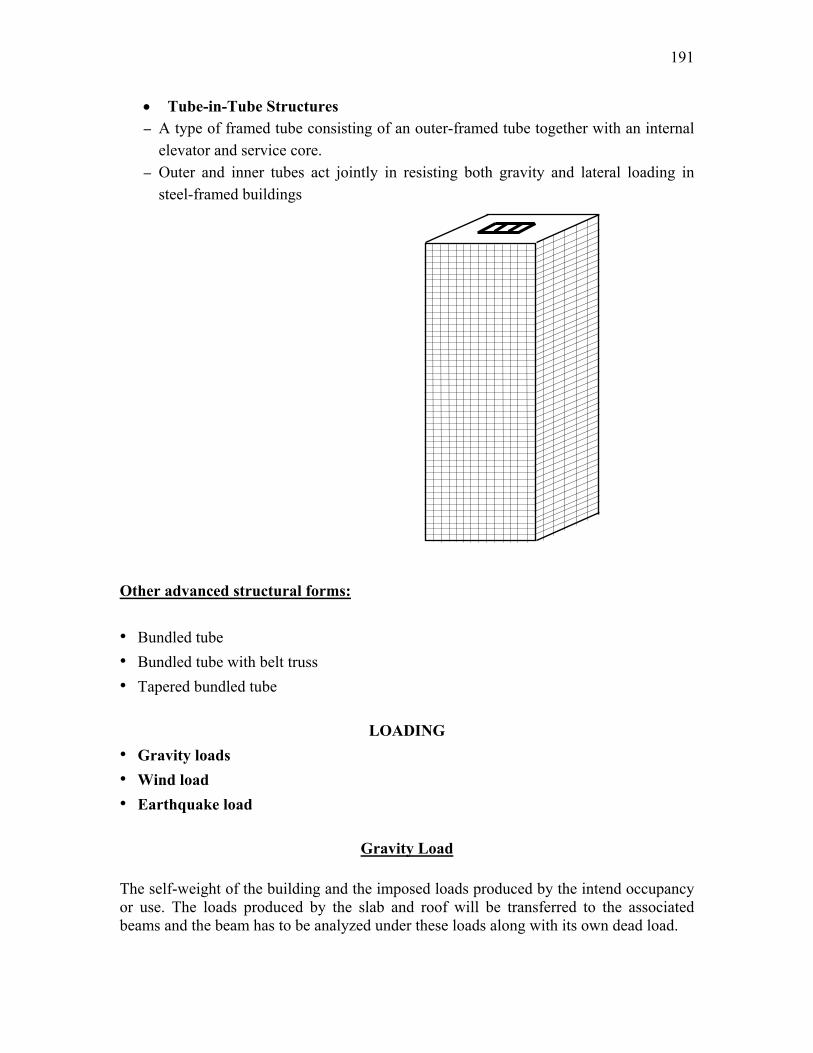
• Tube-in-Tube Structures – A type of framed tube consisting of an outer-framed tube together with an internal
elevator and service core. – Outer and inner tubes act jointly in resisting both gravity and lateral loading in
steel-framed buildings Other advanced structural forms: • Bundled tube • Bundled tube with belt truss • Tapered bundled tube
LOADING • Gravity loads • Wind load • Earthquake load
Gravity Load
The self-weight of the building and the imposed loads produced by the intend occupancy or use. The loads produced by the slab and roof will be transferred to the associated beams and the beam has to be analyzed under these loads along with its own dead load.
192
Analysis of Buildings for Gravity Loads • Simple Framing
– Shears and moments can be determined by static analysis • Semi Rigid Framing
– Designed using techniques developed based on experiments • Rigid Framing
– Rigid frame buildings are analysed by one of approximate methods to make an estimate of member sizes before going to exact methods such as slope-deflection or moment-distribution method
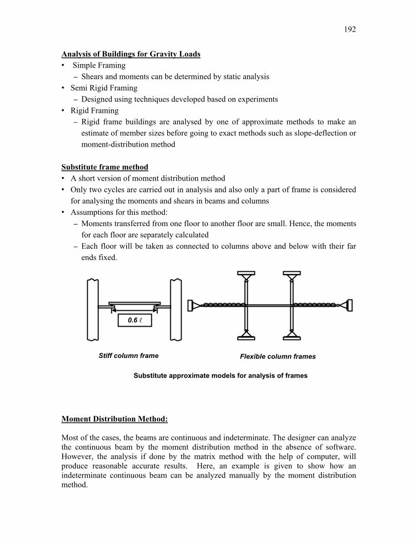
Substitute frame method • A short version of moment distribution method • Only two cycles are carried out in analysis and also only a part of frame is considered
for analysing the moments and shears in beams and columns • Assumptions for this method:
– Moments transferred from one floor to another floor are small. Hence, the moments for each floor are separately calculated
– Each floor will be taken as connected to columns above and below with their far ends fixed.
Moment Distribution Method: Most of the cases, the beams are continuous and indeterminate. The designer can analyze the continuous beam by the moment distribution method in the absence of software. However, the analysis if done by the matrix method with the help of computer, will produce reasonable accurate results. Here, an example is given to show how an indeterminate continuous beam can be analyzed manually by the moment distribution method.
0.6
Stiff column frame Flexible column frames
Substitute approximate models for analysis of frames
193
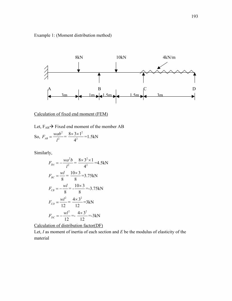
Example 1: (Moment distribution method)
8kN 10kN 4kN/m
A B C D 3m 1m 1.5m 1.5m 3m
Calculation of fixed end moment (FEM) Let, FAB Fixed end moment of the member AB
So, 2
2ABwabF
l= =
2
2
8 3 14
× × =1.5kN
Similarly,
2
2BAwa bF
l= − =
2
2
8 3 14
× × =4.5kN
8BCwlF = = 10 3
8× =3.75kN
8CBwlF = − = -10 3
8× =-3.75kN
2
12CDwlF = =
24 312× =3kN
2
12DCwlF = − =-
24 312× =-3kN
Calculation of distribution factor(DF) Let, I as moment of inertia of each section and E be the modulus of elasticity of the material
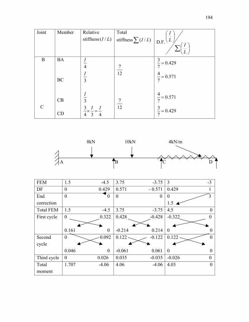
194
Joint Member Relative stiffness ( / )I L
Total stiffness ( / )I L∑ D.F.
∑
LI
LI
B C
BA BC CB CD
4I
3I
3I
34 3 4
I I× =
7
12
7
12
3 0.4297
=
4 0.5717
=
4 0.5717
=
3 0.4297
=
8kN 10kN 4kN/m A B C D FEM 1.5 -4.5 3.75 -3.75 3 -3 DF 0 0.429 0.571 - 0.571 0.429 1 End correction
0 0 0 0 0 3 1.5
Total FEM 1.5 -4.5 3.75 -3.75 4.5 0First cycle 0 0.322
0.161 0
0.428 -0.428 -0.214 0.214
-0.322 0 0 0
Second cycle
0 0.092 0.046 0
0.122 -0.122 -0.061 0.061
0.122 0 0 0
Third cycle 0 0.026 0.035 -0.035 -0.026 0 Total moment
1.707 -4.06 4.06 -4.06 4.03 0
195
Wind load
• Most important factor that determines the design of tall buildings over 10 storeys,
where storey height approximately lies between 2.7 – 3.0 m • Appropriate design wind loads are estimated based on:
– Static approach – Dynamic approach
Earthquake load • Seismic motion consists of horizontal and vertical ground motions • Vertical motion is much smaller in magnitude and factor of safety provided against
gravity loads will accommodate additional forces due to this motion • Horizontal motion of ground causes most significant effect on structure by shaking
foundation back and forth • Mass of building resists this motion by setting up inertia forces throughout structure. • Magnitude of horizontal shear force depends on;
– Mass of building – Acceleration of ground – Nature of structure
• Earthquake load is estimated by; – Seismic co-efficient method – Response spectrum method
196
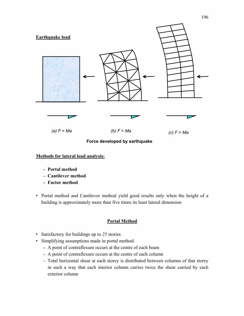
Earthquake load Methods for lateral load analysis:
– Portal method – Cantilever method – Factor method
• Portal method and Cantilever method yield good results only when the height of a
building is approximately more than five times its least lateral dimension
Portal Method
• Satisfactory for buildings up to 25 stories • Simplifying assumptions made in portal method:
– A point of contraflexure occurs at the centre of each beam – A point of contraflexure occurs at the centre of each column – Total horizontal shear at each storey is distributed between columns of that storey
in such a way that each interior column carries twice the shear carried by each exterior column
(a) F = Ma (c) F > Ma (b) F < Ma
Force developed by earthquake
197
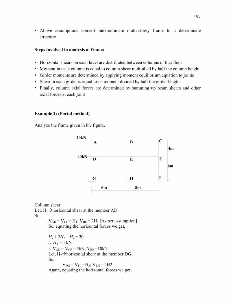
A B C
D E F
G H I
4m
6m
6m 8m
20kN
40kN
• Above assumptions convert indeterminate multi-storey frame to a determinate structure
Steps involved in analysis of frame: • Horizontal shears on each level are distributed between columns of that floor • Moment in each column is equal to column shear multiplied by half the column height • Girder moments are determined by applying moment equilibrium equation to joints • Shear in each girder is equal to its moment divided by half the girder length • Finally, column axial forces are determined by summing up beam shears and other
axial forces at each joint Example 2: (Portal method)
Analyze the frame given in the figure. Column shear Let, H1 horizontal shear at the member AD So,
VAD = VCF = H1; VBE = 2H1 [As per assumption] So, equating the horizontal forces we get, H1 + 2H1 + H1 = 20
51 =∴ H kN ∴VAD = VCF = 5kN; VBE =10kN Let, H2 horizontal shear at the member DG So, VDG = VFI = H2; VEH = 2H2 Again, equating the horizontal forces we get,
198
AB
5kN
20kN A
10kN
3.33kN VBC
5kN
20kN A
10kN
3.33kN VBC
AB
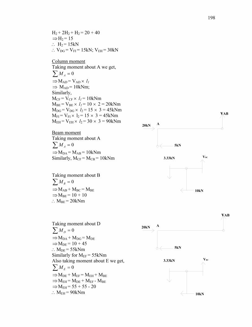
H2 + 2H2 + H2 = 20 + 40 ⇒ H2 = 15 ∴ H2 = 15kN ∴VDG = VFI = 15kN; VEH = 30kN Column moment Taking moment about A we get,
0=∑ AM ⇒ MAD = VAD × l1 ⇒ MAD = 10kNm; Similarly, MCF = VCF × l1 = 10kNm MBE = VBE × l1 = 10 × 2 = 20kNm MDG = VDG × l2 = 15 × 3 = 45kNm MFI = VFI × l2 = 15 × 3 = 45kNm MEH = VEH × l2 = 30 × 3 = 90kNm Beam moment Taking moment about A
0=∑ AM ⇒ MDA = MAB = 10kNm Similarly, MCF = MCB = 10kNm Taking moment about B
0=∑ BM ⇒ MAB + MBC = MBE ⇒ MBE = 10 + 10 ∴MBE = 20kNm Taking moment about D
0=∑ DM ⇒ MDA + MDG = MDE ⇒ MDE = 10 + 45 ∴MDE = 55kNm Similarly for MEF = 55kNm Also taking moment about E we get,
0=∑ EM ⇒ MDE + MEF = MEH + MBE ⇒ MEH = MDE + MEF - MBE ⇒ MEH = 55 + 55 - 20 ∴MEH = 90kNm
199
D
1 5 k N
5 k N
20kN
3.33kN
5kN
FBD at A
15kN3.33kN
FBD at B
15kN
10kN
2.5kN3.33kN
5kN
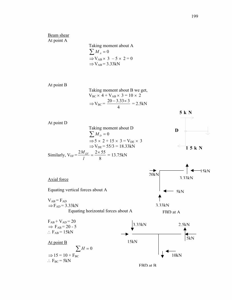
Beam shear At point A
Taking moment about A 0=∑ AM
⇒ VAB × 3 – 5 × 2 = 0 ⇒ VAB = 3.33kN
At point B
Taking moment about B we get, VBC × 4 + VAB × 3 = 10 × 2
⇒ VBC = 4
333.320 ×− = 2.5kN
At point D Taking moment about D
0=∑ DM ⇒ 5 × 2 + 15 × 3 = VDE × 3 ⇒ VDE = 55/3 = 18.33kN
Similarly, VEF = 85522 ×
=l
M EF = 13.75kN
Axial force Equating vertical forces about A VAB = FAD ⇒ FAD = 3.33kN
Equating horizontal forces about A FAB + VAD = 20 ⇒ FAB = 20 - 5 ∴FAB = 15kN At point B 0=∑ H ⇒ 15 = 10 + FBC ∴FBC = 5kN
200
FBD at C
2.5kN
5kN
2.5kN
5kN
FBD at D
15kN
21.67kN
18.33kN
3.33kN5kN
40kN30kN
13.75kN
18.33kN
5.41kN
0.833kN
30kN
10kNE
FBD at E
30kN
FBD at F
13.75kN
10kN
16.25kN
15kN
5kN
2.5kN
F
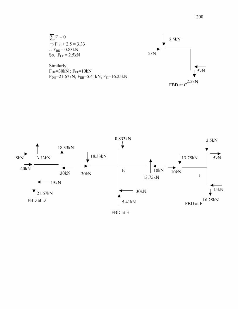
0=∑V
⇒ FBE + 2.5 = 3.33 ∴FBE = 0.83kN So, FCF = 2.5kN Similarly, FDE=30kN ; FEF=10kN FDG=21.67kN; FEH=5.41kN; FFI=16.25kN
201
Lecture Note – 38
Cantilever Method • Gives good results for high-narrow buildings compared to those from the Portal
method and it may be used satisfactorily for buildings of 25 to 35 storeys tall • Simplifying assumptions:
– A point of contraflexure occurs at centre of each beam – A point of contraflexure occurs at centre of each column – Axial force in each column of a storey is proportional to the horizontal distance of
the column from centre of gravity of all columns of storey under consideration Steps involved:
– Centre of gravity of columns is located – Axial force in one column is assumed as F and axial forces of remaining columns
can be expressed in terms of F by taking moments about centroid of columns of the storey
– Beam shears are determined joint by joint from column axial forces – Beam moments are determined by multiplying shear in beam by half span of beam – Column moments are found joint by joint from beam moments – Column shears are obtained by dividing column moments by half-column heights
202
A B C
D E F
G H I
4m
6m
6m 8m
20kN
40kN
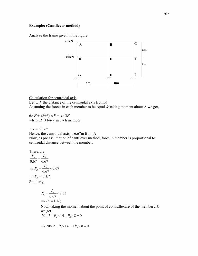
Example: (Cantilever method) Analyze the frame given in the figure Calculation for centroidal axis Let, x the distance of the centroidal axis from A Assuming the forces in each member to be equal & taking moment about A we get, 6×F + (8+6) ×F = x×3F where, F force in each member ∴x = 6.67m Hence, the centroidal axis is 6.67m from A Now, as pre assumption of cantilever method, force in member is proportional to centroidal distance between the member. Therefore
0.67 6.67A BP P
=
0.676.67
AB
PP⇒ = ×
0.1B AP P⇒ = Similarly,
7.336.67
AC
PP = ×
1.1C AP P⇒ = Now, taking the moment about the point of contraflexure of the member AD
we get 20 2 14 8 0A BP P× − × − × =
20 2 14 .1 8 0A AP P⇒ × − × − × =
203
2.7AP⇒ = Hence, PA = 2.7kN (t) So, PB = 0.1PA=0.1×2.7 = 0.27kN (t) PC = 1.1PA=1.1×2.7 = 2.97kN (c) For bottom storey Now, taking the moment about the point of contraflexure of the member DG
we get
/ /20 7 40 3 14 8 0A BP P× + × − × − × = Here also, force in member is proportional to centroidal distance between the member. Hence
/ /0.1B AP P= ; / /1.1C AP P= So putting the values in the above equation we get
/ 17.57AP = kN Similarly,
/ 1.757BP = kN; / 19.32CP = kN Beam shear Now, Shear in the beam AB = Axial force in the column AD Hence, VAB=PA=2.7kN Similarly, Similarly, MBC = VBC × 4 = 0.27 × 4 = 1.08kNm MDE = VDE × 3 = 17.57 × 3 = 52.71kNm MEF = VEF × 4 =19.32 × 4 = 77.28kNm Column moment Taking moment about A
0=∑ AM ⇒ MDA = MAB = 8.1kNm Similarly, MCF = MCB = 1.08kNm Taking moment about B
0=∑ BM ⇒ MAB + MBC = MBE ⇒ MBE = 8.1+1.08 ∴MBE = 9.18kNm Taking moment about D
0=∑ DM ⇒ MDA + MDG = MDE ⇒ MDG = MDA + MDE
204
20kN2.7kN
2.7kN
4.05kN
FBD at A
15.95kN
FBD at B
15.95kN
0.999kN
0.297kN2.7kN
B 5.96kN
0.27kN
⇒ MDG = 8.1 + 52.71 ∴MDG = 60.81kNm Also taking moment about F we get,
0=∑ FM ⇒ MFC + MFI = MFE ⇒ MFI=77.28 -1.08 MFI=76.2kN Also taking moment about E we get,
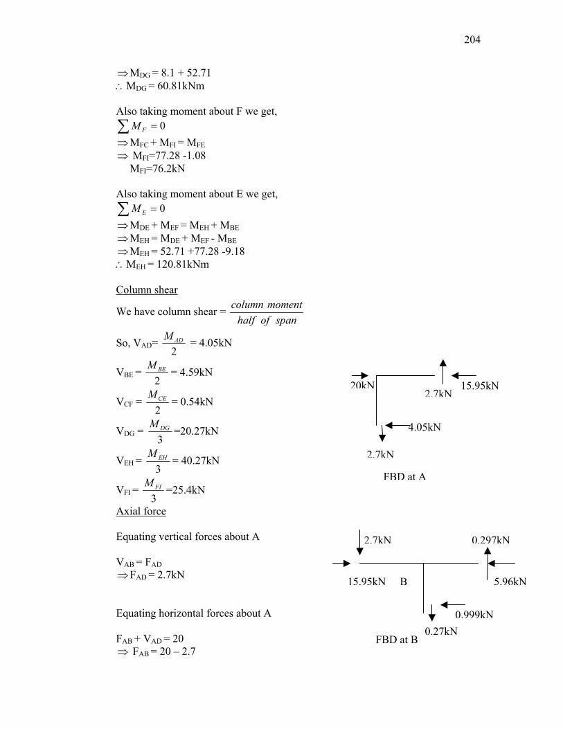
0=∑ EM ⇒ MDE + MEF = MEH + MBE ⇒ MEH = MDE + MEF - MBE ⇒ MEH = 52.71 +77.28 -9.18 ∴MEH = 120.81kNm Column shear
We have column shear = column momenthalf of span
So, VAD= 2
ADM = 4.05kN
VBE = 2
BEM = 4.59kN
VCF = 2CEM
= 0.54kN
VDG = 3DGM
=20.27kN
VEH = 3EHM = 40.27kN
VFI = 3
FIM =25.4kN
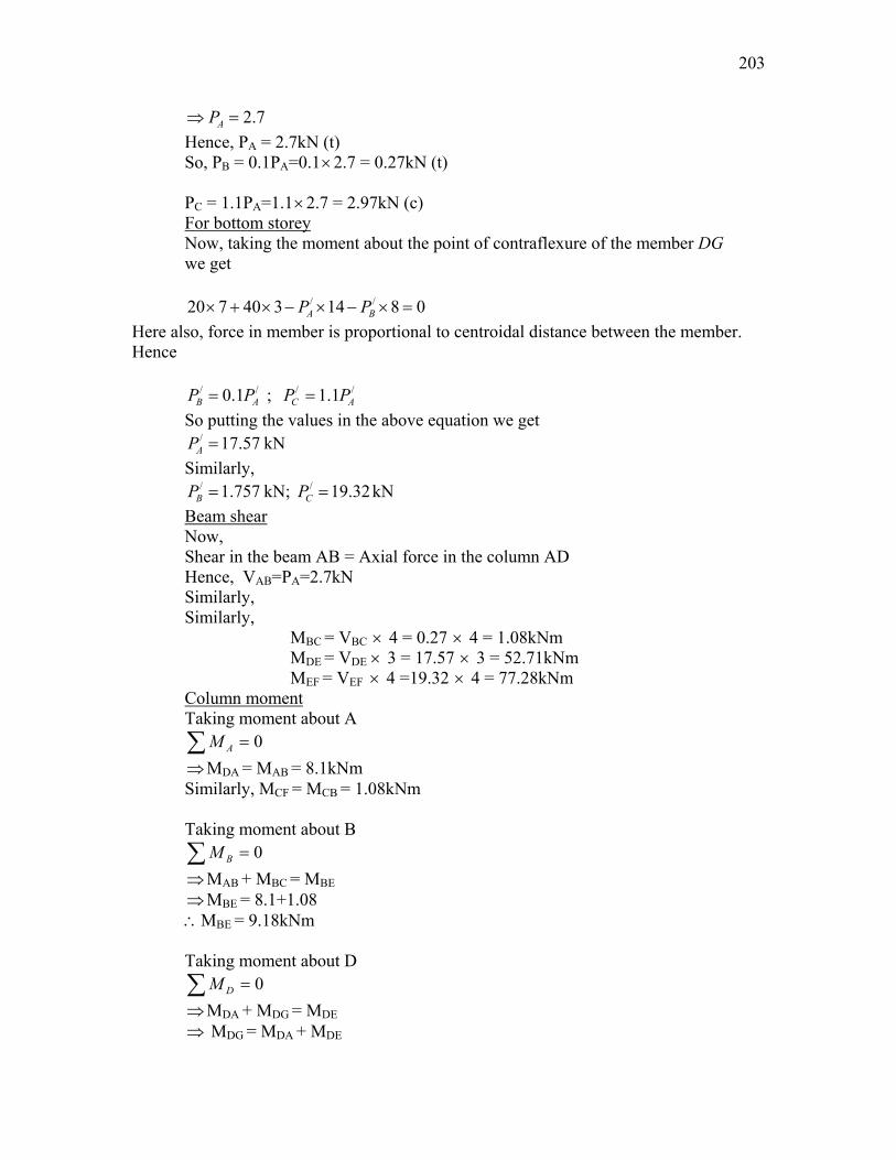
Axial force Equating vertical forces about A VAB = FAD ⇒ FAD = 2.7kN Equating horizontal forces about A FAB + VAD = 20 ⇒ FAB = 20 – 2.7
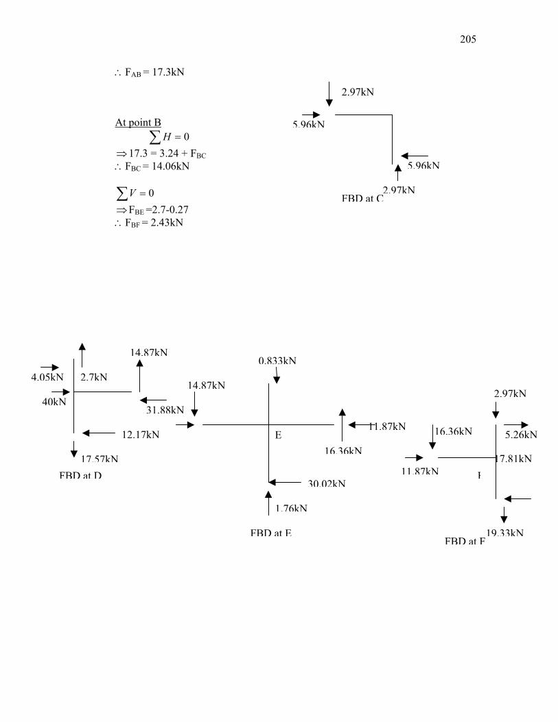
205
FBD at C
2.97kN
5.96kN
2.97kN
5.96kN
16.36kN
1.76kN
0.833kN
30.02kN
E
FBD at E
14.87kN
FBD at D
31.88kN
17.57kN
14.87kN
2.7kN4.05kN
40kN
12.17kN
2.97kN
∴FAB = 17.3kN At point B 0=∑ H ⇒ 17.3 = 3.24 + FBC ∴FBC = 14.06kN
0=∑V
⇒ FBE =2.7-0.27 ∴FBF = 2.43kN
11.87kN
FBD at F1
5.26kN
F
16.36kN
11.87kN
17.81kN9.33kN
206
Factor Method • More accurate than either portal method or cantilever method • Based on assumptions regarding the elastic action of the structure • For application of Factor method, relative stiffness (k = I/ ), for each beam and
column should be known or assumed Application of Factor method involves following steps:
– The girder factor g, is determined for each joint from the following expression
Σ kc - Sum of relative stiffness of column members meeting at that joint Σ k - Sum of relative stiffness of all members meeting at that joint
– Column factor c, is found for each joint from following expression c = 1-g
– At each end of every member, there will be factors from step 1 or step 2. To these factors, half the values of those at the other end of the same member are added
– Sum obtained as per above step is multiplied by relative stiffness of respective
members. This product is termed as column moment factor C, for columns and girder moment factor G, for girders
– Calculate column end moments – Calculate beam end moments
Drift in Rigid Frames • Lateral displacement of rigid frames subjected to horizontal loads is due to following
three modes: – Girder Flexure
∑∑=
k
ckg

207
– Column Flexure – Axial deformation of columns
• Sum of storey drifts from the base upward gives drift at any level and the storey drifts can be calculated from summing up contributions of all three modes in that particular storey
Computer Analysis of Rigid Frames • A typical model of rigid frame consists of an assembly of beam-type elements to
represent both beams and columns of frame. • Columns are assigned their principal inertia and sectional areas. • Beams are assigned with their horizontal axis inertia and sectional areas.