composite marine boiler - vertical type cmb-vsmaytau.ut.edu.vn/userfiles/files/saacke marine...
TRANSCRIPT

SAACKE DOCUMENT NUMBER Revision Page
SMS 3-0001-0103/2 1.0 1/99
Table of contents
2010-10-12
Operating manual
Composite marine boiler - Vertical type
CMB-VS
Shipyard.:
Hull No.:
SAACKE No.:
1.0 2011-06-14 First Edition KOTHES! hnh
Rev Date DD/MM/YY
STATUS WRITTEN BY (name & visa)
CHECKED BY (name & visa)
APPROVED BY (name & visa)
DOCUMENT REVISIONS
Sections changed in last revision are identified by a vertical line in the right margin
Any unauthorized copying, disclosure or distribution of the information in this documents is strictly forbidden

Composite marine boiler - Vertical type CMB-VS
Table of contents
2010-10-12 2
Read this Operation Manual thoroughly before starting any work!
This Operation Manual provides important information on how to work with the system. Strict compliance with all specified safety notes and instructions is a prerequisite for work safety.
Moreover, the accident prevention instructions and general safety regulations applicable at the place of use of the system must also be complied with.
This Operation Manual is part of the system, must always be kept in its vicinity and should be available for the personnel at any time.
The enclosed operating instructions for the installed components apply alongside this Operation Manual. Strictly observe the notes contained therein – especially the safety notes!
Treat this Operation Manual confidentially!
This Operation Manual is intended only for persons working with or on the system. Passing this Operation Manual on to third parties without the written consent of the manufacturer is not permitted.
The contents of this Operation Manual, texts, drawings, pictures and other representations are protected by copyright law subject to industrial property rights. Any misuse is punishable.
Reproduction of any kind – even in the form of excerpts – as well as the use and/or disclosure of the contents without the written consent of the manufacturer is not permitted. Violations require compensation.Created by:
© 2008
SAACKE GmbH & Co. KG Südweststraße 13 D-28237 Bremen
Tel.: +49 421 6495-0 Fax: +49 421 6495-224
E-Mail: [email protected] Internet: www.saacke.de

Composite marine boiler - Vertical type CMB-VS
Table of Contents
2010-10-12 3
Table of Contents
1 General.................................................................................... 5
1.1 Explanation of Symbols and Signal Words ................... 5
1.2 List of Abbreviations ...................................................... 6
1.3 Reference Documents................................................... 6
1.4 Limitation of liability ....................................................... 6
2 Safety ...................................................................................... 7
2.1 General Safety Instructions ........................................... 7
2.2 Intended Use ................................................................. 8
2.3 Costumer's Responsibility ............................................. 9
2.3.1 Product Safety.............................................. 10
2.3.2 Work Safety.................................................. 10
2.3.3 Safety Regulations ....................................... 11
2.4 Personal Safety Equipment......................................... 12
2.5 Special Dangers .......................................................... 12
2.6 System Control ............................................................ 17
2.6.1 Operating Personnel .................................... 17
2.7 Conduct in a dangerous situation and in case of accidents ..................................................................... 19
3 Structure and function ........................................................ 20
3.1 Structure ...................................................................... 20
3.1.1 Overview ...................................................... 20
3.1.2 Boiler Description ......................................... 22
3.2 Functioning principle.................................................... 23
3.2.1 Visualization of the functioning principle...... 23
3.2.2 Description of the functioning principle ........ 24
3.3 Auxiliary equipment ..................................................... 25
4 Transport, packing and storage......................................... 27
4.1 Safety notes................................................................. 27
4.2 Transport inspection .................................................... 29
4.3 Symbols on the packing .............................................. 29
4.4 Transport of the boiler ................................................. 30
4.4.1 Preparing the boiler for transport ................. 30
4.4.2 Transporting the boiler ................................. 31
4.4.3 Transporting the boiler to the mounting site 31
4.5 Packing........................................................................ 32
4.6 Storage ........................................................................ 33
5 Installation and commissioning......................................... 34
5.1 Safety notes................................................................. 34
Composite marine boiler - Vertical type CMB-VS
Table of Contents
2010-10-12 4
5.2 Requirements for the place of set-up .......................... 35
5.3 Assembly and Installation............................................ 36
5.3.1 Transporting the boiler to the mounting site 37
5.3.2 Installing the boiler with welding skirt........... 38
5.3.3 Installing the boiler at the mounting site....... 38
5.3.4 Installation of exhaust gas connections ....... 39
5.3.5 Installation of boiler mountings and instruments when delivered as loose items . 39
5.3.6 Maximum force and momentum to be applied on boiler connections ...................... 40
5.4 Commissioning ............................................................ 41
6 Testing and approval procedure........................................ 43
7 Operation .............................................................................. 44
7.1 Safety........................................................................... 44
7.2 Checks before Start-up................................................ 47
7.3 Start-up routine............................................................ 47
7.4 During operation (Maintenance on daily basis) ........... 48
7.5 Shut-down ................................................................... 50
7.5.1 Regular shut-down procedure...................... 50
7.5.2 Long-term shut-down ................................... 51
7.6 Dry running the exhaust gas section under certain conditions .................................................................... 54
8 Malfunctions and Troubleshooting.................................... 56
8.1 Safety notes................................................................. 56
8.2 Action during malfunctions .......................................... 60
8.3 Troubleshooting........................................................... 65
8.4 Temporary repair of smoke tubes ............................... 67
9 Maintenance ......................................................................... 69
9.1 Safety........................................................................... 69
9.2 Maintenance and inspection chart............................... 75
9.2.1 Inspection of the boiler ................................. 77
9.2.2 Soot cleaning ............................................... 80
9.2.3 Blowing off the water level gauges .............. 84
9.3 Spare parts .................................................................. 85
9.4 Measures after maintenance....................................... 85
9.5 SAACKE Aftersales Service........................................ 86
10 Index 87

SAACKE DOCUMENT NUMBER Revision Page
SMS 3-0001-0103/2 1.0 5/99
1 General Pos: 1.3 /KN2006- Proj ekte/Saacke M arine Systems/GCU/Allgemei nes /1.1 Symboler klär ung allgemeine Gefahren @ 35\mod_1176289288073_2.doc @ 431532
1.1 Explanation of Symbols and Signal Words
Warnings In this Operation Manual warnings are identified by symbols. These warnings are moreover introduced by signal words, which express the severity of a hazard. Adhere to these warnings and act cautiously in order to avoid accidents, personal injuries and damage to property.
DANGER!
… indicates an imminently hazardous situation which, if not avoided, will result in death or serious injury.
WARNING!
… indicates a potentially hazardous situation which, if not avoided, could result in death or serious injury.
CAUTION!
… indicates a potentially hazardous situation which, if not avoided, may result in property damage.
Pos : 1.4 /KN2006- SM/nL---------- Abschnit tsende ---------- @ 8\mod_1141997892953_0.doc @ 75473
Pos: 1.5 /KN2006- Proj ekte/Saacke M arine Systems/GCU/Allgemei nes /1.1.1 Besonder e Sicherheitshi nweise_Titel (Saacke) @ 35\mod_1176289350840_2.doc @ 431546
Safety notes on special dangers The following symbols are used to highlight particular dangers: Pos : 1.6 /KN2006- Proj ekte/Saacke M arine Systems/GCU/Allgemei nes /1.1.1.0 Besonder Sicher hei tshi nweise_Inhalt @ 35\mod_1176290840150_2.doc @ 431618
DANGER!
Danger to life caused by electric current!
… highlights life threatening situations caused by electric current. There is a danger of serious injury or death if the safety notes are not complied with.
WARNING!
Burn hazard from hot surfaces!
… highlights situations caused by hot surfaces that may result in severe burns if the safety notes are not complied with.
WARNING!
Scalding hazard from hot media!
… highlights situations caused by hot media, e. g. boil-off gas, that may result in severe burns if the safety notes are not complied with.
Composite marine boiler - Vertical type CMB-VS
General
2010-10-12 6
Pos : 1.7 /KN2006- SM/nL---------- Abschnit tsende ---------- @ 8\mod_1141997892953_0.doc @ 75473
Pos: 1.8 /KN2006- Proj ekte/Saacke M arine Systems/GCU/Allgemei nes /1.1.1.1 Hinweise @ 35\mod_1176292095277_2.doc @ 431650
Hints and recommendations
NOTE!
… emphasizes useful hints and recommendations
as well as information for efficient and problem free
operation. Pos : 1.9 /KN2006- SM/nL---------- Abschnit tsende ---------- @ 8\mod_1141997892953_0.doc @ 75473
os: 1.10 /KN2006- Proj ekte/Saacke M arine Systems/Boil er/Allgemeines /1.1 Abkürzungen (CMB- VS) @ 92\mod_1233140611482_2.doc @ 1393325
1.2 List of Abbreviations
CMB-VS: Composite marine boiler-Vertical type
IMO: International Maritime Organization
USCG: United States Coast Guard Pos: 1.11 /KN 2006-SM /nL.. ... ... .. Sei tenumbr uch .. ... ... .. @ 8\mod_1141998334703_0.doc @ 71.12 /KN 2006-Proj ekte/Saacke M arine Systems/Boiler/Allgemei nes/1.1 Refer enzdokumente (CMB- VS) @ 92\mod_1233140618482_2.doc @ 1393360
1.3 Reference Documents
� Documentation of water level gauges 8\mod_1141998334703_0.doc @ 75491os : 1.14 /KN2006-SM /Allgemeines/130 1.1 Haftungsbeschränkung @ 8\mod_1142091543501_2.doc @ 75812
1.4 Limitation of liability
All information and notes in this Manual were compiled under due consideration of valid standards and regulations, the present status of technology and our years of knowledge and experience.
The manufacturer can not be made liable for damage resulting from:
� disregarding this Manual
� unintended use
� employment of untrained personnel
� unauthorized conversions
� technical modifications
� use of unapproved spare parts
In case of customised versions the actual scope of delivery can vary from the explanations and representations in this Manual, because of the utilization of additional options or due to latest technical changes.
Apart from this, the obligations agreed upon in the delivery contract, the general terms and conditions and the delivery conditions of the manufacturer and the legal regulations valid at the time of contract do apply.
Pos: 2.1 /KN2006- SM/nL.... ... ... Seitenumbr uch . ... ... ... @ 8\mod_1141998334703_0.doc @ 75491

Composite marine boiler - Vertical type CMB-VS
Safety
2010-10-12 7
Pos : 2.2 /KN2006- SM/Sicherheit/001 1 Sicher hei t_Titel @ 8\mod_1142425976781_2.doc @ 77463
2 Safety Pos: 2.3 /KN2006- Proj ekte/Saacke M arine Systems/Boil er/Sicherheit/Einführung (CMB-HF) @ 90\mod_1229610730261_2.doc @ 1377528
This section offers an overview of all important safety aspects.
In addition to this, concrete notes on safety to avert danger are provided and marked with symbols in the individual chapters. Furthermore, any pictograms, signs and labels on the system are to be observed and kept legible at all times.
Compliance with all safety notes enables optimal protection of personnel against danger and ensures safe and disruption-free operation of the system.
Pos : 2.4 /KN2006- SM/nL---------- Abschnit tsende ---------- @ 8\mod_1141997892953_0.doc @ 75473
Pos: 2.5 /KN2006- Proj ekte/Saacke M arine Systems/Boil er/Sicherheit/1.1 Allgemei ne Sicher hei tshi nweise (CMB-HF) @ 90\mod_1229611166879_2.doc @ 1377550
2.1 General Safety Instructions
The system is built according to the currently applicable rules of technology and is safe to operate.
However, this system may become a danger if it is not used professionally by trained personnel, or if it is used improperly or not according to the designated purpose.
Each person authorized to carry out work on or with the system must have read and understood the operating manual before starting work. This also applies if the person in question has already worked on just such a system or a similar system or was trained by the manufacturer.
Knowledge of the contents of the operating manual is one of the prerequisites for protecting personnel from danger and for avoiding faults; this means the system will be operated safely and without disruption.
Neither changes nor conversions may be carried out on the system, which have not been explicitly authorized by the manufacturer, to avoid dangers and to ensure optimal performance.
All safety notices and operating signs on the system must be kept well legible at all times. Damaged or illegible signs must be replaced immediately.
The setting values and/or value ranges stated in the operating manual must be complied with.
The operator is advised to get proof of confirmation that personnel have acknowledged the contents of the operating manual.
Pos : 2.6 /KN2006- SM/nL.... ... ... Seitenumbr uch . ... ... ... @ 8\mod_1141998334703_0.doc @ 75491
Composite marine boiler - Vertical type CMB-VS
Safety
2010-10-12 8
Pos : 2.7 /KN2006- Proj ekte/Saacke M arine Systems/Boil er/Sicherheit/1.1 Bes ti mmungsgemäße Verwendung (CMB-VS) @ 91\mod_1232469499794_2.doc @ 1386083
2.2 Intended Use
The operational safety of the system is only guaranteed when used in the intended manner corresponding to the information in the operating manual.
The Composite Boiler CMB-VS serves exclusively for the production of saturated steam by means of waste heat utilization and combustion of marine fuel oils. The steam itself is to be used for domestic and machinery applications on ocean vessels.
WARNING!
Danger arising from unintended use!
Any use exceeding the before mentioned use and/or any use different to the use specified above can cause dangerous situations.
Therefore:
– Use the system only for the purpose it is intended for.
– Strictly comply with all information in this operation manual and the contractual stipulations.
– Neither convert, modify nor manipulate system components.
Intended use also includes correct adherence to assembly, operating, maintenance and cleaning instructions and the manuals of the supporting components as well as compliance with operating ranges and conditions.
Claims of any kind against the manufacturer and/or his authorized representatives resulting from damage caused by non-intended use of the system are excluded. The customer is solely liable for any damage occurring during non-intended use.
Pos: 2.8 /KN2006- SM/nL.... ... ... Seitenumbr uch . ... ... ... @ 8\mod_1141998334703_0.doc @ 75491

Composite marine boiler - Vertical type CMB-VS
Safety
2010-10-12 9
Pos : 2.9 /KN2006- Proj ekte/Saacke M arine Systems/Boil er/Sicherheit/1.4 Ver antwortung des Betrei bers (CMB-HF) @ 90\mod_1229680615534_2.doc @ 1378246 Organizati onal M easures reg ardi ng Safety
2.3 Costumer's Responsibility
� This operating manual and the operating manuals of the supporting components are to be kept in direct proximity to the system and must be accessible at all times to installation, operating, maintenance and cleaning personnel.
� All safety features must be accessible at all times and checked regularly for fault-free functioning.
� The system may only be operated in a technically perfect condition and if operationally safe. Never operate an faulty or
potentially unsafe system!
� In case of malfunctions, the customer is obliged to limit the damage, to take measures against consequential loss, to notify the manufacturer of the malfunction and to repair the boiler as described in this manual. For repairs that are not described herein, immediately contact the manufacturer’s customer service (see Chapter "Maintenance", paragraph "SAACKE After Sales Service").
The customer is obliged to determine compliance of work safety measures specified with the current status of legal statutes and to observe any new regulations over the entire period in which the system is used. Details about work safety refer to European Union regulations valid at the time the system was manufactured. Outside of the European Union, the work safety laws and regional state conditions for the place of use of the system are to be complied with.
The generally valid safety guidelines and accident prevention guidelines as well as the valid environmental conditions for the area where the system is used are to be observed and adhered to alongside the work safety notes in this operating manual.
The customer and personnel authorized by him/her are responsible for the disruption-free operation of the system as well as for unambiguous determination of responsibilities during installation, operation, maintenance and cleaning of the system.
Composite marine boiler - Vertical type CMB-VS
Safety
2010-10-12 10
Details of the operating manual must be adhered to without limitation!
Furthermore, the customer must also ensure that:
� Other dangers that result from special working conditions at the place where the system is used are determined in a risk assessment according to work protection law.
� All other instructions and safety notes that result from the risk assessment of workplaces at the system are summarized in an operating manual according to the regulation regarding the use of work materials.
� All personal safety equipment required according to this manual is provided.
� In particular, ear defenders must be installed near the blow down valve close to hand for fast depressurization.
2.3.1 Product Safety
� Keep away any water, rain, dust completely during installation and maintenance. Avoid any open instruments (Refer to the ingress protection class in normal operation).
2.3.2 Work Safety
Danger to persons and/or the system can be prevented by following the notes regarding work safety.
Non-compliance with these notes can endanger persons and objects resulting from mechanical or electrical influences or from the system breaking down.
Non-compliance with safety conditions leads to a loss of any claims to compensation.

Composite marine boiler - Vertical type CMB-VS
Safety
2010-10-12 11
2.3.3 Safety Regulations
Comply with the following marine-related safety regulations:
� Class rules
� IMO Codes (SOLAS, IMDG, ..)
� USCG accident prevention regulations
� Country specific regulations
Occupational Safety and Accident
Prevention Measures
The accident prevention measures are laid down in rules that are stipulated on a binding basis. They are:
� Guidelines and codes of practice
� Laws and regulations of the respective country
� Regulations of the USCG regarding accident prevention
WARNING!
Non- compliance with safety provisions and
accident prevention rules may present a hazard
to life and limb!
Therefore:
– Get yourself informed about laws and regulations of your respective country.
– Adhere at all costs to these provisions. Pos : 2.10 /KN 2006-SM /nL.. ... ... .. Sei tenumbr uch .. ... ... .. @ 8\mod_1141998334703_0.doc @ 75491

Composite marine boiler - Vertical type CMB-VS
Safety
2010-10-12 12
Pos : 2.11 /KN 2006-Pr ojekte/Saacke Mari ne Sys tems/Boiler/Sicher heit /1.1 Persönliche Schutzausr üstung (CMB-HF) @ 90\mod_1229690492783_2.doc @ 1378459
2.4 Personal Safety Equipment
In principle, the following is to be worn when working on the system:
Pos : 2.12 /KN 2006-Pr ojekte/Saacke Mari ne Sys tems/Boiler/Sicher heit /feuerfeste Arbeitsschutzkl eidung (CMB-HF) @ 91\mod_1229695472564_2.doc @ 1378614
Fireproof protective clothing
to protect against burns. Never wear clothes of synthetic fibre in the machine room!
Pos : 2.13 /KN 2006-Pr ojekte/Saacke Mari ne Sys tems/Boiler/Sicher heit /Sicherheitsschuhe (CM B-HF) @ 91\mod_1229695513111_2.doc @ 1378660
Safety boots
to protect against heavy, falling parts and slipping on non-skidproof ground.
Pos : 2.14 /KN 2006-Pr ojekte/Saacke Mari ne Sys tems/Boiler/Sicher heit /Schutzhandschuhe (CMB-HF) @ 90\mod_1229695308096_2.doc @ 1378568
Protective gloves
to protect the hands against hot surfaces and chemicals.
Pos : 2.15 /KN 2006-Pr ojekte/Saacke Mari ne Sys tems/Boiler/Sicher heit /Für spezi elle Arbeiten (CMB-HF) @ 91\mod_1229696178778_2.doc @ 1378749
For special kinds of work on the system the following is to be
worn additionally: Pos : 2.16 /KN 2006-Pr ojekte/Saacke Mari ne Sys tems/Boiler/Sicher heit /extra feuerfeste Arbeitsschutzkl eidung (CM B-HF) @ 91\mod_1229696096185_2.doc @ 1378727
Heavy fireproof protective clothing, for any hot work such as welding work or fire cutting to protect against burns.
Pos : 2.17 /KN 2006-Pr ojekte/Saacke Mari ne Sys tems/Boiler/Sicher heit /Gesichtsschutz (CMB-HF) @ 91\mod_1229695495220_2.doc @ 1378637
Face protection, when effecting any hot work such as welding work or fire cutting to protect the eyes and the face against injuries.
Pos : 2.18 /KN 2006-Pr ojekte/Saacke Mari ne Sys tems/Boiler/Sicher heit /Schutzhelm (CMB-HF) @ 91\mod_1229695529657_2.doc @ 1378683
Hard hat, when lifting system components to protect the head against falling parts.
Pos : 2.19 /KN 2006-SM /nL---------- Abschnittsende ---------- @ 8\mod_1141997892953_0.doc @ 75473
Pos: 2.20 /KN 2006-Pr ojekte/Saacke Mari ne Sys tems/Boiler/Sicher heit /1.2 Besondere Gefahren_Titel und Einl eitung (CMB-HF) @ 90\mod_1229612519799_2.doc @ 1377597
2.5 Special Dangers
The system was subjected to a risk analysis. The resultant construction and design of the system corresponds to the current status of technology.
However, there is still the possibility of residual dangers. Pos: 2.21 /KN 2006-SM /nL---------- Abschnittsende ---------- @ 8\mod_1141997892953_0.doc @ 75473
Composite marine boiler - Vertical type CMB-VS
Safety
2010-10-12 13
Pos : 2.22 /KN 2006-Pr ojekte/Saacke Mari ne Sys tems/Boiler/Sicher heit /1.2.0 Besondere Gefahren: Chemische Substanzen (CMB-HF) @ 90\mod_1229627018878_2.doc @ 1377985
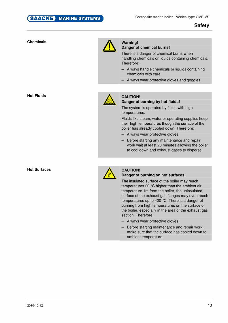
Chemicals
Warning!
Danger of chemical burns!
There is a danger of chemical burns when handling chemicals or liquids containing chemicals. Therefore:
– Always handle chemicals or liquids containing chemicals with care.
– Always wear protective gloves and goggles. Pos : 2.23 /KN 2006-SM /nL---------- Abschnittsende ---------- @ 8\mod_1141997892953_0.doc @ 75473
Pos: 2.24 /KN 2006-Pr ojekte/Saacke Mari ne Sys tems/Boiler/Sicher heit /1.2.0 Besondere Gefahren: Heiße M edi en (CMB-HF) @ 90\mod_1229613693692_2.doc @ 1377666
Hot Fluids
CAUTION!
Danger of burning by hot fluids!
The system is operated by fluids with high temperatures.
Fluids like steam, water or operating supplies keep their high temperatures though the surface of the boiler has already cooled down. Therefore:
– Always wear protective gloves.
– Before starting any maintenance and repair work wait at least 20 minutes allowing the boiler to cool down and exhaust gases to disperse.
Pos : 2.25 /KN 2006-SM /nL---------- Abschnittsende ---------- @ 8\mod_1141997892953_0.doc @ 75473
Pos: 2.26 /KN 2006-Pr ojekte/Saacke Mari ne Sys tems/Boiler/Sicher heit /1.2.0 Besondere Gefahren: Heiße Oberfl ächen (CMB-HF) @ 90\mod_1229622314684_2.doc @ 1377872
Hot Surfaces
CAUTION!
Danger of burning on hot surfaces!
The insulated surface of the boiler may reach temperatures 20 °C higher than the ambient air temperature 1m from the boiler, the uninsulated surface of the exhaust gas flanges may even reach temperatures up to 420 °C. There is a danger of burning from high temperatures on the surface of the boiler, especially in the area of the exhaust gas section. Therefore:
– Always wear protective gloves.
– Before starting maintenance and repair work, make sure that the surface has cooled down to ambient temperature.
Pos : 2.27 /KN 2006-SM /nL---------- Abschnittsende ---------- @ 8\mod_1141997892953_0.doc @ 75473
Composite marine boiler - Vertical type CMB-VS
Safety
2010-10-12 14
Pos : 2.28 /KN 2006-Pr ojekte/Saacke Mari ne Sys tems/Boiler/Sicher heit /1.2.0 Besondere Gefahren: El ektrischer Str om (CMB-HF) @ 90\mod_1229626091280_2.doc @ 1377918
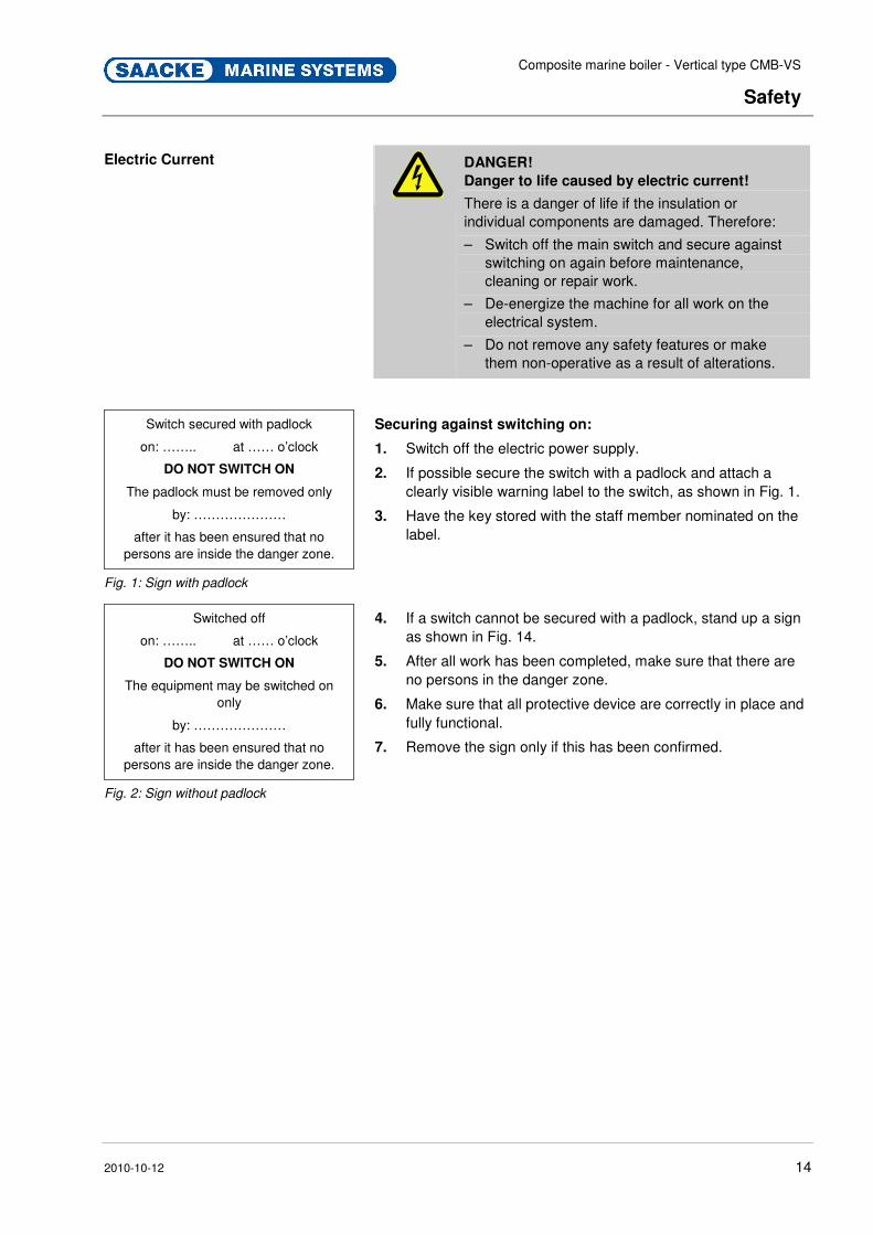
Electric Current
DANGER!
Danger to life caused by electric current!
There is a danger of life if the insulation or individual components are damaged. Therefore:
– Switch off the main switch and secure against switching on again before maintenance, cleaning or repair work.
– De-energize the machine for all work on the electrical system.
– Do not remove any safety features or make them non-operative as a result of alterations.
Switch secured with padlock
on: …….. at …… o’clock
DO NOT SWITCH ON
The padlock must be removed only
by: …………………
after it has been ensured that no persons are inside the danger zone.
Fig. 1: Sign with padlock
Securing against switching on:
1. Switch off the electric power supply.
2. If possible secure the switch with a padlock and attach a clearly visible warning label to the switch, as shown in Fig. 1.
3. Have the key stored with the staff member nominated on the label.
Switched off
on: …….. at …… o’clock
DO NOT SWITCH ON
The equipment may be switched on only
by: …………………
after it has been ensured that no persons are inside the danger zone.
Fig. 2: Sign without padlock
4. If a switch cannot be secured with a padlock, stand up a sign as shown in Fig. 14.
5. After all work has been completed, make sure that there are no persons in the danger zone.
6. Make sure that all protective device are correctly in place and fully functional.
7. Remove the sign only if this has been confirmed.
Pos : 2.29 /KN 2006-SM /nL---------- Abschnittsende ---------- @ 8\mod_1141997892953_0.doc @ 75473

Composite marine boiler - Vertical type CMB-VS
Safety
2010-10-12 15
Pos : 2.30 /KN 2006-Pr ojekte/Saacke Mari ne Sys tems/GCU /Sicher heit/1.2.0 Besondere Gefahr en: Lär m @ 37\mod_1178085322224_2.doc @ 456548
Noise
WARNING!
Hearing damage caused by noise!
The noise level in the direct proximity of the fans may reach harmful levels possibly leading to severe hearing damage!
Therefore:
– In general, wear ear defenders when working in the proximity of fans in operation.
– Only stay inside the periphery of the fans as long as absolutely necessary.
Pos : 2.31 /KN 2006-SM /nL---------- Abschnittsende ---------- @ 8\mod_1141997892953_0.doc @ 75473
Pos: 2.32 /KN 2006-Pr ojekte/Saacke Mari ne Sys tems/Boiler/Sicher heit /1.2.0 Besondere Gefahren: Medien unter Druck (CMB-HF) @ 90\mod_1229625550903_2.doc @ 1377894
Pressurized media
WARNING!
Danger of injury from pressurized media!
The system is operated with media under pressure.
In case of damage, malfunction or human failure media may escape under high pressure causing severe injury, especially to the eyes. Therefore:
– Never open/loosen/remove boiler components when boiler is pressurized.
– Comply with operating pressure ranges.
– In case of damage to pressure vessel, steam system, directly installed boiler mountings or the exhaust gas section as well as before starting maintenance and repair work, make sure that the system is depressurized.
– When depressurizing be careful not to depressurize the boiler by blowing off the steam through the vent valve or safety valves. Otherwise they will be damaged.
Pos : 2.33 /KN 2006-SM /nL---------- Abschnittsende ---------- @ 8\mod_1141997892953_0.doc @ 75473

Composite marine boiler - Vertical type CMB-VS
Safety
2010-10-12 16
Pos : 2.34 /KN 2006-Pr ojekte/Saacke Mari ne Sys tems/GCU /Sicher heit/1.2.0 Besondere Gefahr en: Stickstoff @ 37\mod_1177758729479_2.doc @ 454823
Nitrogen
WARNING!
Danger of suffocation under high
concentration of nitrogen!
High concentrations of escaping nitrogen can cause unconsciousness with inability to move finally leading to suffocation.
Therefore:
– Strictly follow the safety data sheet issued by the manufacturer.
– In case of suffocation symptoms immediately provide fresh air for the affected person. Consult the on-board-physician.
– In case of respiratory standstill apply first aid measures with artificial breathing.
– De-pressurize the gas train before conducting any work on it.
Pos : 2.35 /KN 2006-SM /nL---------- Abschnittsende ---------- @ 8\mod_1141997892953_0.doc @ 75473
Pos: 2.36 /KN 2006-Pr ojekte/Saacke Mari ne Sys tems/Boiler/Sicher heit /1.2.0 Besondere Gefahren: Anwendungsumg ebung Schiff (CMB-HF) @ 90\mod_1229627280420_2.doc @ 1377963
Since being installed on a Ship
WARNING!
Danger of injury!
The system is installed on a ship it may move abruptly. Therefore:
– Always stand and walk securely and grip handrail, if possible.
– Keep in mind that the floor may be slippery.
– Keep in mind that levels of liquids may vary.
Humid Air
ATTENTION!
Danger of material damage!
The system is installed in a surrounding with humid and damp air. Therefore:
– Use a dehumidificating agent to preserve the boiler perfectly.
Pos : 2.37 /KN 2006-SM /nL---------- Abschnittsende ---------- @ 8\mod_1141997892953_0.doc @ 75473
Pos: 2.38 /KN 2006-SM /Sicher hei t/007 Besondere Gefahr en/Scharfe Kanten, spitze Ecken_Vorsicht! @ 8\mod_1143378164691_2.doc @ 81404
Sharp corners and pointed edges
CAUTION!
Danger of injuring on corners and edges!
Sharp corners and pointed edges can cause graze and cuts in the skin.
Therefore:
– Take care when working near sharp corners and pointed edges.
– Wear protective gloves, if in doubt. Pos : 2.39 /KN 2006-SM /nL.. ... ... .. Sei tenumbr uch .. ... ... .. @ 8\mod_1141998334703_0.doc @ 75491

Composite marine boiler - Vertical type CMB-VS
Safety
2010-10-12 17
Pos : 2.40 /KN 2006-Pr ojekte/Saacke Mari ne Sys tems/Boiler/Sicher heit /1.1 Systemkontr olle (CM B-HF) @ 90\mod_1229694611069_2.doc @ 1378544
2.6 System Control
The system is used within an overall plant and does not have its own control system. The customer must make sure that the system is connected to the system control of the overall plant in agreement with the applicable accident prevention guidelines.
For this purpose, the following points are to be observed:
� If there is a power failure, the control system must cut all connection lines. The system may not proceed in an uncontrolled way after the power supply has been re-established.
� The system control must recognize an electrical short circuit and cut all connection phases immediately.
� Protection features on the system are to be connected to the system control.
Pos: 2.41 /KN 2006-SM /nL.. ... ... .. Sei tenumbr uch .. ... ... .. @ 8\mod_1141998334703_0.doc @ 75491 Pos : 2.42 /KN 2006-Pr ojekte/Saacke Mari ne Sys tems/Boiler/Sicher heit /1.1 Personal (CMB-HF) @ 90\mod_1229686544324_2.doc @ 1378267
2.6.1 Operating Personnel
Qualifications The system may only be operated and maintained by authorized, qualified and instructed personnel. These personnel must have received special instructions regarding any dangers that may occur.
An instructed person is someone who has been taught about and if necessary instructed practically in the tasks entrusted to them and the possible dangers resulting from improper actions; and who has been instructed both about the necessary protective features and about protective measures.
Qualified personnel include those who can assess the work entrusted to them and recognize potential dangers based on their specialist training, knowledge and experience as well as their knowledge of appropriate conditions.
If personnel do not have the necessary knowledge, then they are to be trained accordingly.
Responsibilities for operation and maintenance must be clearly determined and adhered to so that an unclear division of competency does not occur with regard to safety.
The system may only be operated and maintained by persons who can be expected to carry out their work reliably. For this purpose, any mode of operation that adversely affects the safety of persons, the environment or the system is to be avoided. Persons who are under the influence of drugs, alcohol or medication that affects their responsiveness may under no
circumstances carry out work on or with the system.

Composite marine boiler - Vertical type CMB-VS
Safety
2010-10-12 18
When selecting personnel, attention must be paid to the regulations protecting young workers in the relevant country regarding the minimum age and, if necessary, to the job-related instructions based on this.
The operator must also ensure that no unauthorized persons work on or with the system. Unauthorized persons, such as visitors etc., may not come into contact with the system. They must keep an appropriate safety distance.
The operator is obliged to report immediately any changes to the system which adversely affect safety to the operator.
Unauthorized Persons
WARNING! Danger for unauthorized persons!
Persons not meeting the requirements outlined here are not aware of the dangers in the work area.
Therefore:
– Keep unauthorized persons away from the work area.
– If in doubt, address the persons and direct them to leave the work area.
– Interrupt work activities as long as unauthorized persons are present in the work area.
Pos : 2.43 /KN 2006-SM /nL.. ... ... .. Sei tenumbr uch .. ... ... .. @ 8\mod_1141998334703_0.doc @ 75491
Composite marine boiler - Vertical type CMB-VS
Safety
2010-10-12 19
Pos: 2.44 /KN2006-Projekte/Saacke Marine Systems/Boiler/Sicherheit/1.3 Verhalten im Gefahrenfall und bei Unfällen (CMB-HF) @ 90\mod_1229692777894_2.doc @ 1378523
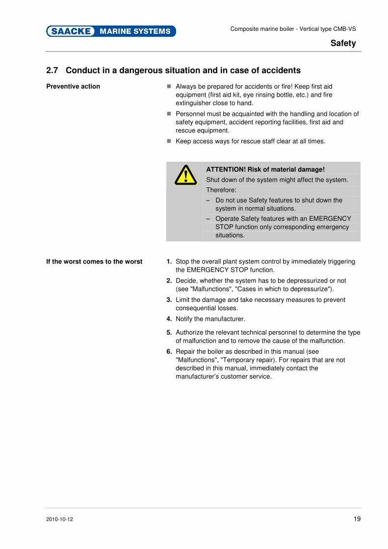
2.7 Conduct in a dangerous situation and in case of accidents
Preventive action
� Always be prepared for accidents or fire! Keep first aid equipment (first aid kit, eye rinsing bottle, etc.) and fire extinguisher close to hand.
� Personnel must be acquainted with the handling and location of safety equipment, accident reporting facilities, first aid and rescue equipment.
� Keep access ways for rescue staff clear at all times.
ATTENTION! Risk of material damage!
Shut down of the system might affect the system.
Therefore:
– Do not use Safety features to shut down the system in normal situations.
– Operate Safety features with an EMERGENCY STOP function only corresponding emergency situations.
If the worst comes to the worst 1. Stop the overall plant system control by immediately triggering the EMERGENCY STOP function.
2. Decide, whether the system has to be depressurized or not (see "Malfunctions", "Cases in which to depressurize").
3. Limit the damage and take necessary measures to prevent consequential losses.
4. Notify the manufacturer.
5. Authorize the relevant technical personnel to determine the type of malfunction and to remove the cause of the malfunction.
6. Repair the boiler as described in this manual (see "Malfunctions", "Temporary repair). For repairs that are not described in this manual, immediately contact the manufacturer’s customer service.
Pos : 3.1 /KN2006- SM/nL.... ... ... Seitenumbr uch . ... ... ... @ 8\mod_1141998334703_0.doc @ 75491

Composite marine boiler - Vertical type CMB-VS
Structure and function
2010-10-12 20
Pos : 3.2 /KN2006- SM/Aufbau und Funktion/001 1 Aufbau und Funkti on_Titel @ 8\mod_1143713625726_2.doc @ 83163
3 Structure and function Pos: 3.3 /KN2006- Proj ekte/Saacke M arine Systems/Boil er/Aufbau und Funktion/002 1.1 Struktur_Titel (CMB- VS) @ 91\mod_1232474721890_2.doc @ 1386561
3.1 Structure Pos : 3.4 /KN2006- Proj ekte/Saacke M arine Systems/Boil er/Aufbau und Funktion/003 1.1.1 Ü bersicht_Titel (CMB- VS) @ 91\mod_1232476645855_2.doc @ 1386652
3.1.1 Overview Pos: 3.5 /KN2006- Proj ekte/Saacke M arine Systems/Boil er/Aufbau und Funktion/003 1.1.1 Ü bersicht_Inhalt (CMB- VS) @ 91\mod_1232470879709_2.doc @ 1386157
Fig. 3: Overview composite boiler top CMB-VS
1 Exhaust gas outlet 2 Exhaust gas outlet chamber 3 Pressure vessel end plate 4 Pressure vessel shell 5 Hand holes 6 Outside insulation 7 Exhaust inlet chamber 8 Exhaust gas inlet 9 Chambers inspection doors
10 Support ring 11 Furnace bottom refactory 12 Furnace drain valve 13 Fire box furnace
14 Burner refactory 15 Pressure gauge board 16 Smoke tubes of oil fired section 17 Feed water inlet valves 18 Water sampling valve 19 Defoaming valve 20 Water level gauges 21 Safety valves 22 Water level electrodes 23 Main steam outlet valve 24 Flue gas outlet chamber 25 Flue gas outlet NWL Normal water level
Composite marine boiler - Vertical type CMB-VS
Structure and function
2010-10-12 21
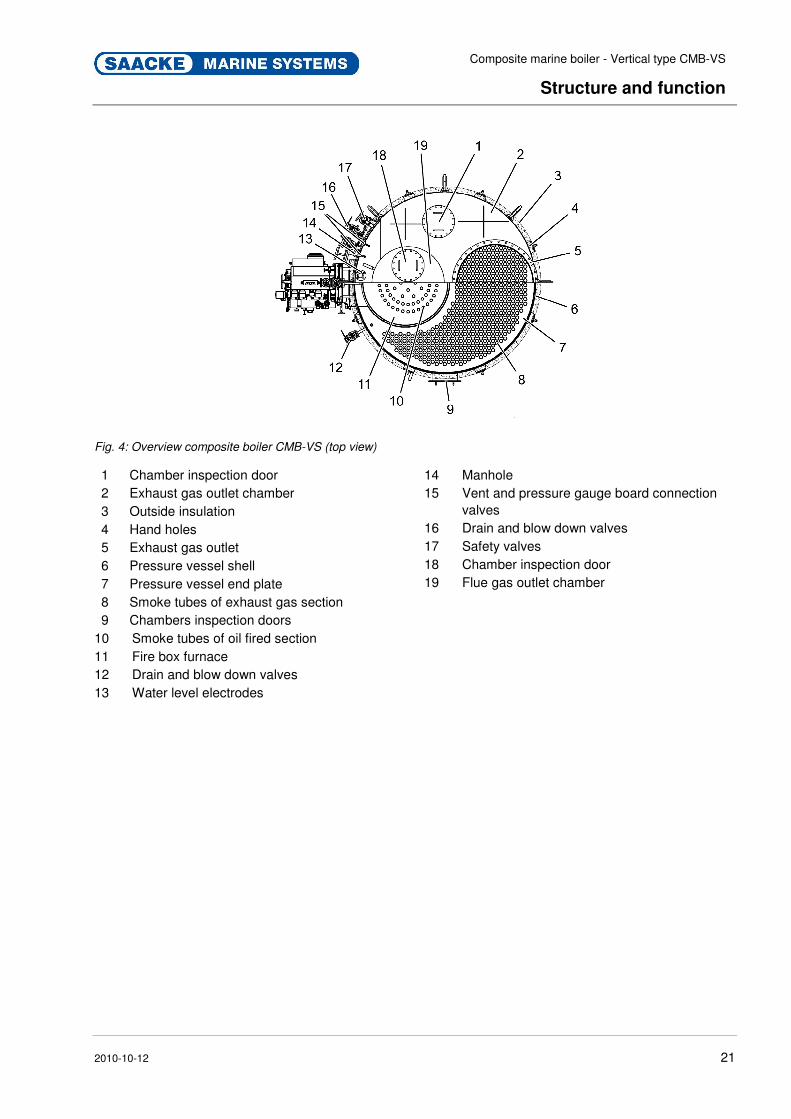
Fig. 4: Overview composite boiler CMB-VS (top view)
1 Chamber inspection door 2 Exhaust gas outlet chamber 3 Outside insulation 4 Hand holes 5 Exhaust gas outlet 6 Pressure vessel shell 7 Pressure vessel end plate 8 Smoke tubes of exhaust gas section 9 Chambers inspection doors
10 Smoke tubes of oil fired section 11 Fire box furnace 12 Drain and blow down valves 13 Water level electrodes
14 Manhole 15 Vent and pressure gauge board connection
valves 16 Drain and blow down valves 17 Safety valves 18 Chamber inspection door 19 Flue gas outlet chamber
Pos: 3.6 /KN2006- SM/nL.... ... ... Seitenumbr uch . ... ... ... @ 8\mod_1141998334703_0.doc @ 75491
Composite marine boiler - Vertical type CMB-VS
Structure and function
2010-10-12 22
Pos : 3.7 /KN2006- Proj ekte/Saacke M arine Systems/Boil er/Aufbau und Funktion/004 1.1.1 Boil er Descripti on_Titel (CMB- VS) @ 91\mod_1232474155245_2.doc @ 1386356
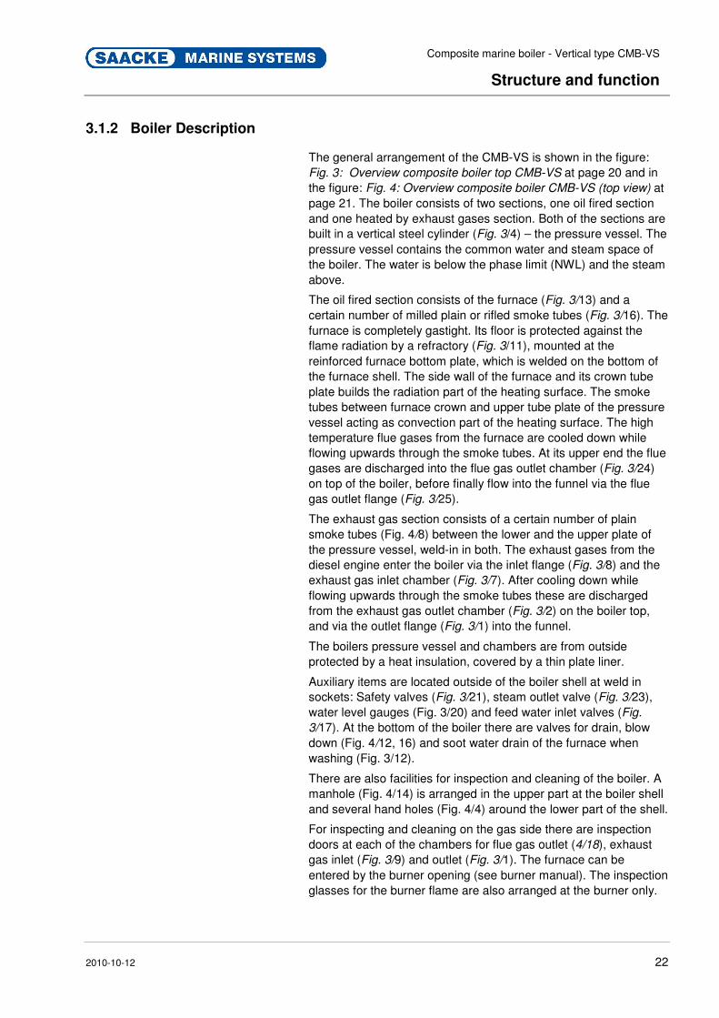
3.1.2 Boiler Description Pos : 3.8 /KN2006- Proj ekte/Saacke M arine Systems/Boil er/Aufbau und Funktion/004 1.1.1 Boil er Descripti on_T ext (CMB-VS) @ 91\mod_1232474989266_2.doc @ 1386606
The general arrangement of the CMB-VS is shown in the figure: Fig. 3: Overview composite boiler top CMB-VS at page 20 and in the figure: Fig. 4: Overview composite boiler CMB-VS (top view) at page 21. The boiler consists of two sections, one oil fired section and one heated by exhaust gases section. Both of the sections are built in a vertical steel cylinder (Fig. 3/4) – the pressure vessel. The pressure vessel contains the common water and steam space of the boiler. The water is below the phase limit (NWL) and the steam above.
The oil fired section consists of the furnace (Fig. 3/13) and a certain number of milled plain or rifled smoke tubes (Fig. 3/16). The furnace is completely gastight. Its floor is protected against the flame radiation by a refractory (Fig. 3/11), mounted at the reinforced furnace bottom plate, which is welded on the bottom of the furnace shell. The side wall of the furnace and its crown tube plate builds the radiation part of the heating surface. The smoke tubes between furnace crown and upper tube plate of the pressure vessel acting as convection part of the heating surface. The high temperature flue gases from the furnace are cooled down while flowing upwards through the smoke tubes. At its upper end the flue gases are discharged into the flue gas outlet chamber (Fig. 3/24) on top of the boiler, before finally flow into the funnel via the flue gas outlet flange (Fig. 3/25).
The exhaust gas section consists of a certain number of plain smoke tubes (Fig. 4/8) between the lower and the upper plate of the pressure vessel, weld-in in both. The exhaust gases from the diesel engine enter the boiler via the inlet flange (Fig. 3/8) and the exhaust gas inlet chamber (Fig. 3/7). After cooling down while flowing upwards through the smoke tubes these are discharged from the exhaust gas outlet chamber (Fig. 3/2) on the boiler top, and via the outlet flange (Fig. 3/1) into the funnel.
The boilers pressure vessel and chambers are from outside protected by a heat insulation, covered by a thin plate liner.
Auxiliary items are located outside of the boiler shell at weld in sockets: Safety valves (Fig. 3/21), steam outlet valve (Fig. 3/23), water level gauges (Fig. 3/20) and feed water inlet valves (Fig.
3/17). At the bottom of the boiler there are valves for drain, blow down (Fig. 4/12, 16) and soot water drain of the furnace when washing (Fig. 3/12).
There are also facilities for inspection and cleaning of the boiler. A manhole (Fig. 4/14) is arranged in the upper part at the boiler shell and several hand holes (Fig. 4/4) around the lower part of the shell.
For inspecting and cleaning on the gas side there are inspection doors at each of the chambers for flue gas outlet (4/18), exhaust gas inlet (Fig. 3/9) and outlet (Fig. 3/1). The furnace can be entered by the burner opening (see burner manual). The inspection glasses for the burner flame are also arranged at the burner only.

Composite marine boiler - Vertical type CMB-VS
Structure and function
2010-10-12 23
os: 3.9 /KN2006-SM/nL---------- Abschnittsende ---------- @ 8\mod_1141997892953_0.doc @ 75473 Pos: 3.10 /KN 2006-Pr ojekte/Saacke Mari ne Sys tems/Boiler/Aufbau und Funkti on/005 1.1 Func tioning Princi ple_Titel (CMB- VS) @ 91\mod_1232476205102_2.doc @ 1386628
3.2 Functioning principle Pos : 3.11 /KN 2006-Pr ojekte/Saacke Mari ne Sys tems/Boiler/Aufbau und Funkti on/005 1.1.1 Visualizati on of the functi oni ng pri ncipl e_Ti tel (CMB-VS) @ 91\mod_1232476867575_2.doc @ 1386673
3.2.1 Visualization of the functioning principle Pos : 3.12 /KN 2006-Pr ojekte/Saacke Mari ne Sys tems/Boiler/Aufbau und Funkti on/005 1.1.1 Visualizati on of the functi oni ng pri ncipl e_Bild (CM B-VS) @ 91\mod_1232477305312_2.doc @ 1386695
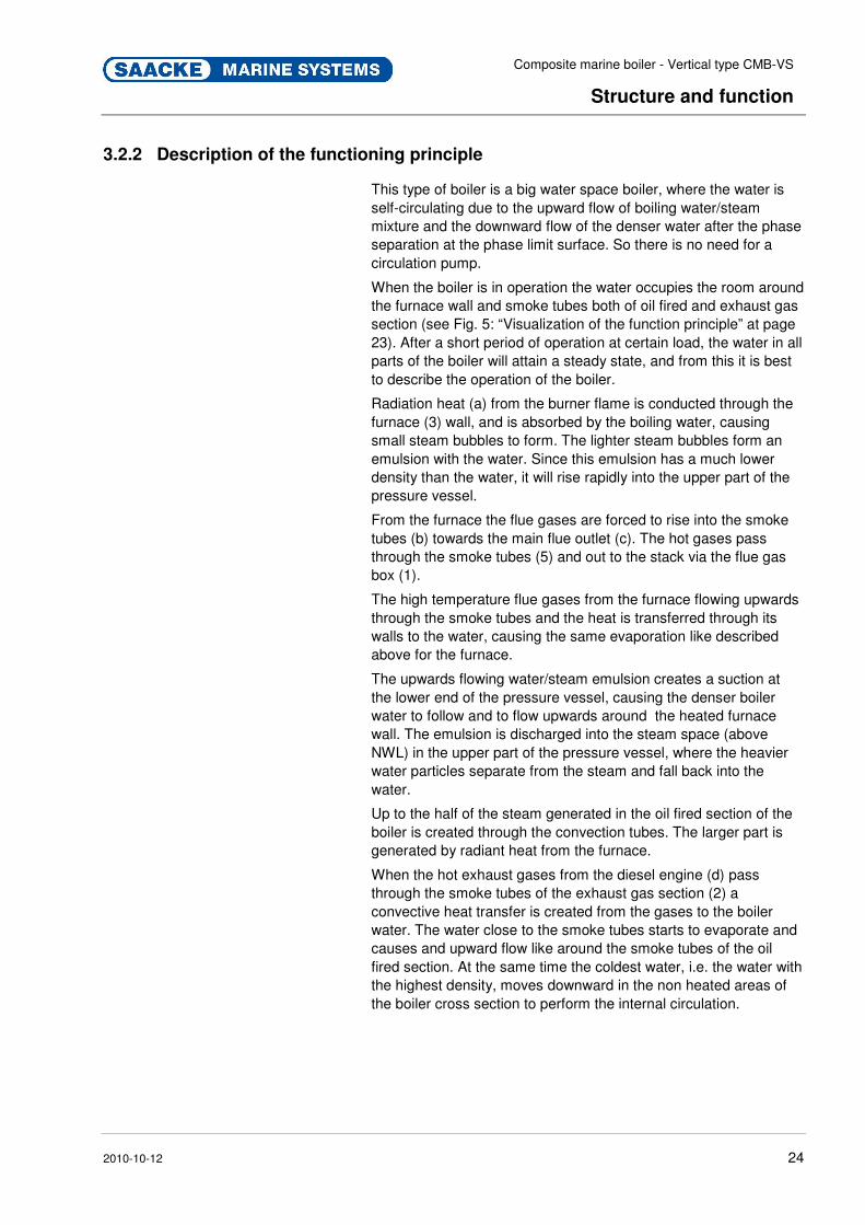
Fig. 5: Visualization of the functioning principle
1 Flue gas outlet chamber (oil fired section) 2 Smoke tubes exhaust gas section 3 Exhaust gas inlet chamber 4 Firebox furnace 5 Outlet gas chamber exhaust gas section 6 Smoke tubes of oil fired section
a Radiant heat b Gas flow from burner c Gas flow: Outlet to flue d Exhaust gas from main engine e Exhaust gas to flue
NWL Normal water level Pos: 3.13 /KN2006-SM/nL.......... Seitenumbruch .......... @ 8\mod_1141998334703_0.doc @ 75491
Composite marine boiler - Vertical type CMB-VS
Structure and function
2010-10-12 24
Pos : 3.14 /KN 2006-Pr ojekte/Saacke Mari ne Sys tems/Boiler/Aufbau und Funkti on/005 1.1.1 Descripti on of the functioni ng principl e_Titel (CMB-VS) @ 91\mod_1232477530720_2.doc @ 1386747
3.2.2 Description of the functioning principle Pos : 3.15 /KN 2006-Pr ojekte/Saacke Mari ne Sys tems/Boiler/Aufbau und F unkti on/005 1.1.1 Descripti on of the functioni ng principl e_T ext (CMB-VS) @ 91\mod_1232477780362_2.doc @ 1386769
This type of boiler is a big water space boiler, where the water is self-circulating due to the upward flow of boiling water/steam mixture and the downward flow of the denser water after the phase separation at the phase limit surface. So there is no need for a circulation pump.
When the boiler is in operation the water occupies the room around the furnace wall and smoke tubes both of oil fired and exhaust gas section (see Fig. 5: “Visualization of the function principle” at page 23). After a short period of operation at certain load, the water in all parts of the boiler will attain a steady state, and from this it is best to describe the operation of the boiler.
Radiation heat (a) from the burner flame is conducted through the furnace (3) wall, and is absorbed by the boiling water, causing small steam bubbles to form. The lighter steam bubbles form an emulsion with the water. Since this emulsion has a much lower density than the water, it will rise rapidly into the upper part of the pressure vessel.
From the furnace the flue gases are forced to rise into the smoke tubes (b) towards the main flue outlet (c). The hot gases pass through the smoke tubes (5) and out to the stack via the flue gas box (1).
The high temperature flue gases from the furnace flowing upwards through the smoke tubes and the heat is transferred through its walls to the water, causing the same evaporation like described above for the furnace.
The upwards flowing water/steam emulsion creates a suction at the lower end of the pressure vessel, causing the denser boiler water to follow and to flow upwards around the heated furnace wall. The emulsion is discharged into the steam space (above NWL) in the upper part of the pressure vessel, where the heavier water particles separate from the steam and fall back into the water.
Up to the half of the steam generated in the oil fired section of the boiler is created through the convection tubes. The larger part is generated by radiant heat from the furnace.
When the hot exhaust gases from the diesel engine (d) pass through the smoke tubes of the exhaust gas section (2) a convective heat transfer is created from the gases to the boiler water. The water close to the smoke tubes starts to evaporate and causes and upward flow like around the smoke tubes of the oil fired section. At the same time the coldest water, i.e. the water with the highest density, moves downward in the non heated areas of the boiler cross section to perform the internal circulation.
Pos: 3.16 /KN 2006-SM /nL.. ... ... .. Sei tenumbr uch .. ... ... .. @ 8\mod_1141998334703_0.doc @ 75491

Composite marine boiler - Vertical type CMB-VS
Structure and function
2010-10-12 25
Pos : 3.17 /KN 2006-Pr ojekte/Saacke Mari ne Sys tems/Boiler/Aufbau und Funkti on/006 1.1 Auxiliar y equi pment_Titel (CMB-VS) @ 91\mod_1232478122599_2.doc @ 1386791
3.3 Auxiliary equipment Pos : 3.18 /KN 2006-Pr ojekte/Saacke Mari ne Sys tems/Boiler/Aufbau und Funkti on/006 1.1 Auxiliar y equi pment_Text (CMB-VS) @ 92\mod_1233065438912_2.doc @ 1392308
Auxiliary equipment for this system is outlined in the list of equipment/order parts list and described in detail in chapter "Documentation of Components" of the boiler system handbook.
The following is a complementary explanation of the most important items:
Main steam valve BO 002
This valve is a shut-off or combined shut-off/non-return valve. When closed, it isolates the boiler from the main steam line. When open, it prevents steam from flowing backwards into the boiler.
Safety valves BO 005
Two safety valves are fitted to the pressure vessel of each boiler. They are designed to prevent the boiler pressure from rising above the design value.
Feedwater valves BO 006/007
Two groups of feed water valves are provided in the boiler. Each group comprises a shut-off valve and a non-return valve. The shut-off valve must be open, when the boiler is in operation, or when the boiler is used as a steam drum for an exhaust gas boiler. The shut-off valves should be closed when the boiler is not in use.
Defoaming valve BO 008
The defoaming valve is a combined shut-off/non-return valve. In the event of foaming in the boiler, the foam can be blown off from the water surface by opening this valve.
Blow-down valves BO 009/010
Two sets of blow down valves are connected to the pressure vessel at the bottom of the boiler, each set being located on the opposite sides of the boiler. Each set comprises a shut-off/non-return valve and a quick-closing valve serving as a blow-down valve. The valves are serial connected. The shut-off function is for security and the non-return function prevents steam/water from flowing into an empty boiler by mistake.
Furnace drain valve BO 011
The furnace drain valve serves the purpose to drain the washing water from the furnace after heating surface cleaning. It is normally closed except when water washing is performed.

Composite marine boiler - Vertical type CMB-VS
Structure and function
2010-10-12 26
Ventilation valve BO 016
The ventilation valve located on top of the boiler is a shut-off valve. It is normally closed except when the boiler is being filled or completely drained.
Water sampling valve BO 017
The water sampling valve located on the shell of the boiler is a shut-off valve which is normally closed. When opened, it supplies the sample cooler with boiler water.
Gauge board valve BO 018
The gauge board valve located on top or on the shell of the boiler is a shut-off vlalve. It is normally open and provides the connection to the pressure indication and monitoring instruments.
Water level gauges BO 019/020
Two local water level gauges are connected to the front of the boiler, each gauge being provided with two shut-off valves and a drain valve. The shut-off valves, which are fitted at the top and bottom of the sight glasses, have a quick-closing equipment with automatic shut-off function in case of broken glass.
Water level transmitter electrode BO 021
The water level transmitter electrode is providing a continuous 4...20 mA signal to the controller and/or limit switch.
Water level limiter electrode BO 022
The water level limiter electrode is a self-monitoring low water level limiter with periodic self-checking and an associated limit switch.
Furnace inspection windows
Two small windows are provided in the furnace wall to enable inspection of the burner flame. A proportion of the air supply is bled off from the FD fan to cool the window glasses, and prevent them from soot deposits.
Manholes and inspection hatches
A manhole on the boiler shell allows inside inspection of the pressure vessel. One or two large inspection hatches on the flue gas boxes enable inspection and cleaning of the smoke tubes in the oil fired section and the exhaust gas section. Access to the furnace is gained by swinging out or taking off the burner unit.
Pos : 4.1 /KN2006- SM/nL.... ... ... Seitenumbr uch . ... ... ... @ 8\mod_1141998334703_0.doc @ 75491 s: 4.2 /KN2006-Projekte/Saacke Marine Systems/Boiler/Transport/001 1 Transport, Verpackung und Lagerung_Titel (CMB-VS) @ 91\mod_1232479317685_2.doc @ 1386860

Composite marine boiler - Vertical type CMB-VS
Transport, packing and storage
2010-10-12 27
4 Transport, packing and storage Pos: 4.3 /KN2006- Proj ekte/Saacke M arine Systems/Boil er/Transport /002 1.1 Safety notes_Titel (CMB- VS) @ 91\mod_1232479295153_2.doc @ 1386881
4.1 Safety notes Pos : 4.4 /KN2006- Proj ekte/Saacke M arine Systems/Boil er/Transport /002 1.1 War nhi nweis_Gefahr durch unzur eichenden Transport (CMB-VS) @ 91\mod_1232479560108_2.doc @ 1386903
Improper transport
WARNING!
Danger by improper transport!
When transporting or loading and unloading falling parts may cause severe injury or death. Units can be damaged or destroyed by improper transporting.
Therefore:
– Never lift loads over people.
– Always move the system with the greatest of care and attention.
– Units must exclusively be lifted on their attachment points.
– Units must never be transported on projecting elements.
– Ropes, chords and other lifting tackle must be equipped with safety hooks.
– Only use ropes, and lifting tackle chords with sufficient bearing capacity.
– No torn or worn ropes may be used.
– Ropes and chords may not be knotted or lie against sharp edges.
– Pay attention to the centre of gravity.
– Wear a hard hat to protect the head against falling parts.
CAUTION!
Improper transport can result in damage!
– When unloading/transporting the packing units exercise caution and observe the symbols on the packages.
– Use only the provided lifting lugs/lashing eyes.
– Make sure that no box or containers are opened or unpacked before destination at yard site.
– All goods, which are packed and transported inside containers or boxes have to be unpacked and stored under weather protected conditions.
Composite marine boiler - Vertical type CMB-VS
Transport, packing and storage
2010-10-12 28
Pos : 4.5 /KN2006- Proj ekte/Saacke M arine Systems/Boil er/Transport /002 1.1 Persönliche Schutzausrüs tung Transport_T ext (CMB-VS) @ 91\mod_1232638120928_2.doc @ 1387872
Protective Gear Wear the following protective gear during transport:
� Protective clothing
� Protective gloves
� Safety boots
� Hard hat
4.2 Transport inspection Pos : 4.8 /KN2006- Proj ekte/Saacke M arine Systems/Boil er/Transport /003 1.1 Transpor tinspektion_Text (CM B-VS) @ 91\mod_1232619133714_2.doc @ 1387463
Check delivery immediately on receipt for completeness and potential transport damage.
CAUTION!
If the following instructions are not complied
with and damage ensues then insurance
company liability can be cancelled!
Therefore:
– Do not accept delivery or only accept under proviso if there is externally recognizable transport damage.
– Note the scope of damage on the transport documents.
– Start complaints procedure.
– Ensure claims for compensation against third parties. Shipping companies, other transporters, warehouse agents, customs and port authorities should:
• be requested to view the damage as well,
• be asked for certification of the damage,
• make it liable in writing and describe the damage in detail.
Make sure any damage is reduced and any further damage is prevented.
Complain about hidden deficiencies as soon as they are discovered as compensation claims can only be asserted within the applicable complaints period.
P: 4.6 /KN 2006-SM/nL... ... ... . Seitenumbruch .... ... ... @ 8\mod_1141998334703_0.doc @ 75491
Composite marine boiler - Vertical type CMB-VS
Transport, packing and storage
2010-10-12 29
Pos : 4.7 /KN2006- Proj ekte/Saacke M arine Systems/Boil er/Transport /003 1.1 Transpor tinspektion_Titel (CMB-VS) @ 91\mod_1232618405791_2.doc @ 1387441
4.3 Symbols on the packing Pos : 4.11 /KN 2006-SM /Transport , Verpackung und Lager ung/003 Symbole auf der Verpackung/Oben @ 9\mod_1144051638161_2.doc @ 84553
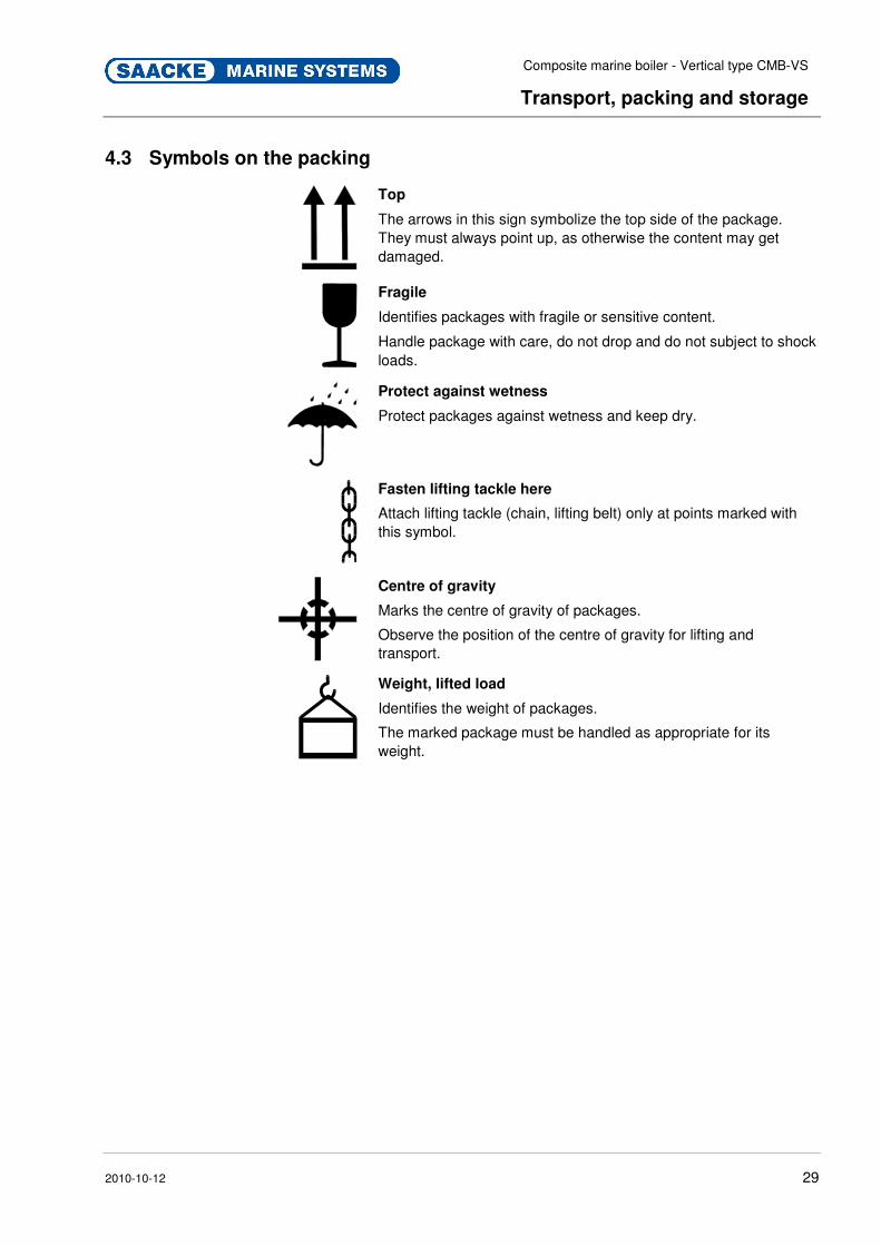
Top
The arrows in this sign symbolize the top side of the package. They must always point up, as otherwise the content may get damaged.
Pos : 4.12 /KN 2006-SM /Transport , Verpackung und Lager ung/003 Symbole auf der Verpackung/Zer brechlich @ 9\mod_1144053717149_2.doc @ 84680
Fragile
Identifies packages with fragile or sensitive content.
Handle package with care, do not drop and do not subject to shock loads.
Pos : 4.13 /KN 2006-SM /Transport , Verpackung und Lager ung/003 Symbole auf der Verpackung/Vor Nässe schützen @ 9\mod_1144053598688_2.doc @ 84673
Protect against wetness
Protect packages against wetness and keep dry.
Pos : 4.14 /KN 2006-SM /Transport , Verpackung und Lager ung/003 Symbole auf der Verpackung/Anschlagen hier @ 9\mod_1144052066800_2.doc @ 84567
Fasten lifting tackle here
Attach lifting tackle (chain, lifting belt) only at points marked with this symbol.
Pos : 4.15 /KN 2006-SM /Transport , Verpackung und Lager ung/003 Symbole auf der Verpackung/Schwer punkt @ 9\mod_1144053236650_2.doc @ 84652
Centre of gravity
Marks the centre of gravity of packages.
Observe the position of the centre of gravity for lifting and transport.
Pos : 4.16 /KN 2006-SM /Transport , Verpackung und Lager ung/003 Symbole auf der Verpackung/Gewicht, Ang eschlagene Las t @ 9\mod_1144052989589_2.doc @ 84645
Weight, lifted load
Identifies the weight of packages.
The marked package must be handled as appropriate for its weight.
Pos : 4.17 /KN 2006-SM /nL.. ... ... .. Sei tenumbr uch .. ... ... .. @ 8\mod_1141998334703_0.doc @ 75491
Composite marine boiler - Vertical type CMB-VS
Transport, packing and storage
2010-10-12 30
Pos : 4.18 /KN 2006-Pr ojekte/Saacke Mari ne Sys tems/Boiler/Transport/004 1.1 Transport of the boiler _Titel (CMB-VS) @ 91\mod_1232619410881_2.doc @ 1387485
4.4 Transport of the boiler Pos : 4.19 /KN 2006-Pr ojekte/Saacke Mari ne Sys tems/Boiler/Transport/005 1.1.1 Preparing the boiler for transport_Titel (CMB- VS) @ 91\mod_1232619583487_2.doc @ 1387507
4.4.1 Preparing the boiler for transport Pos : 4.20 /KN 2006-Pr ojekte/Saacke Mari ne Sys tems/Boiler/Transport/005 1.1.1 Preparing the boiler for transport_Text (CMB-VS) @ 91\mod_1232620011791_2.doc @ 1387529
1. Remove the packing material only at the lifting lugs and around the boiler foundation.
2. Carefully depressurize and subsequently vent the water/steam space in case the boiler had been prepared for long-term storage by pressurized nitrogen filling.
WARNING!
Danger of injury by pressurized gas!
The boiler had been filled with nitrogen under pressure. A substantial overpressure may build up.
Therefore:
– Never open any blinded connection on the boiler body suddenly.
4.4.2 Transporting the boiler Pos : 4.23 /KN 2006-Pr ojekte/Saacke Mari ne Sys tems/Boiler/Transport/006 1.1.1 Transporti ng the boiler_Warnhi nweise (CMB- VS) @ 91\mod_1232620742168_2.doc @ 1387573
WARNING!
Danger of injury from falling elements!
If wrongly transported the boiler may fall and cause severe injuries.
Therefore:
– Before lifting the boiler check the lifting instructions provided with the working drawings for center of gravity coordinates and actual load distribution on the lugs.
Make sure you comply with all safety notes concerning transport of the composite boiler.
– Only use designated lifting lugs (see Fig.).
CAUTION!
Danger of material damage from falling!
If wrongly transported the boiler may fall. This can cause material damage.
Therefore:
– Before lifting the boiler check the lifting instructions provided with the working drawings for center of gravity coordinates and actual load distribution on the lugs.
Make sure you comply with all safety notes concerning transport of the composite boiler.
– Only use designated lifting lugs (see Fig.). Pos : 4.24 /KN 2006-SM /nL.. ... ... .. Sei tenumbr uch .. ... ... .. @ 8\mod_1141998334703_0.doc @ 75491 Pos : 4.21 /KN 2006-SM /nL.. ... ... .. Sei tenumbr uch .. ... ... .. @ 8\mod_1141998334703_0.doc @ 75491
Composite marine boiler - Vertical type CMB-VS
Transport, packing and storage
2010-10-12 31
Pos : 4.22 /KN 2006-Pr ojekte/Saacke Mari ne Sys tems/Boiler/Transport/006 1.1.1 Transporti ng the boiler_Titel (CMB-VS) @ 91\mod_1232620560562_2.doc @ 1387551 Pos : 4.25 /KN 2006-Pr ojekte/Saacke Mari ne Sys tems/Boiler/Transport/006 1.1.1 Transporti ng the boiler_Bild (CMB-VS) @ 91\mod_1232634388234_2.doc @ 1387597
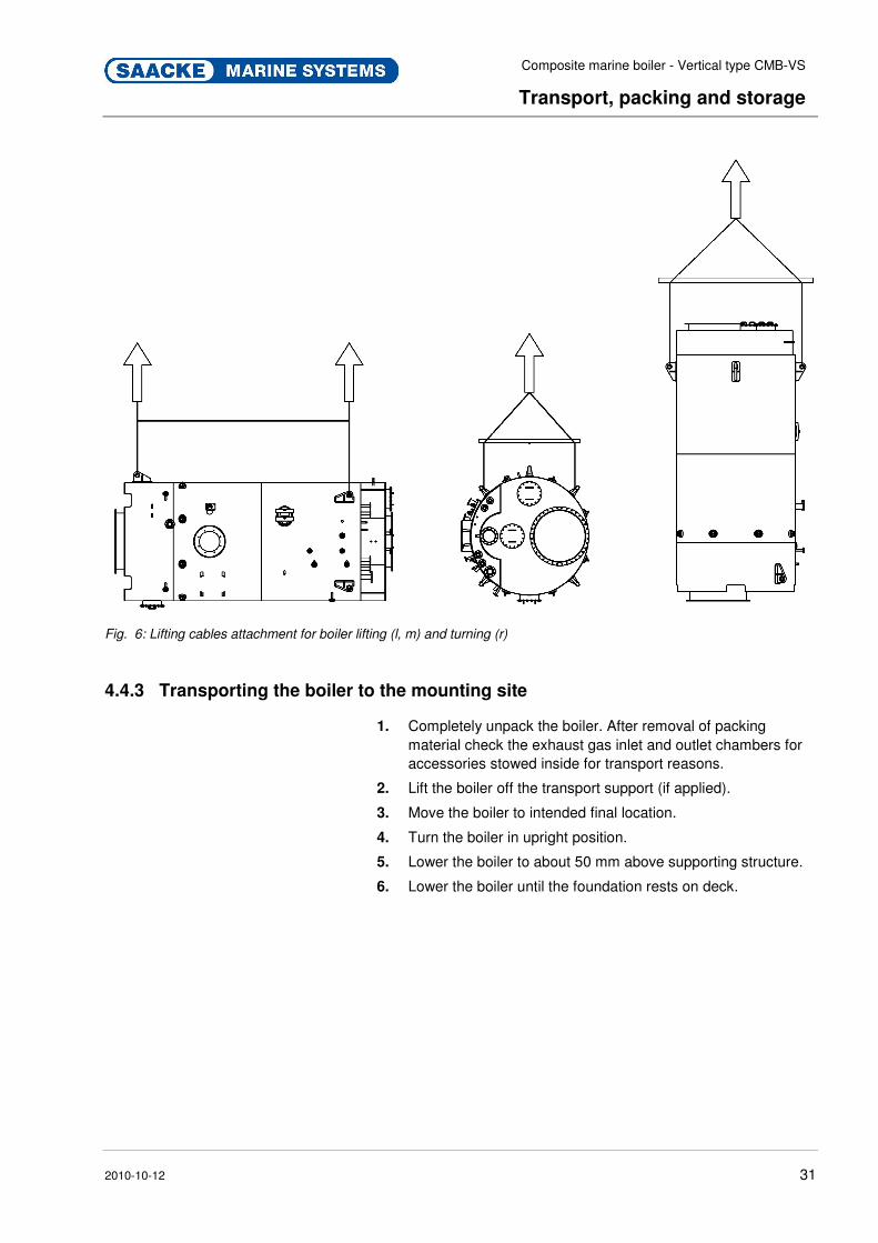
Fig. 6: Lifting cables attachment for boiler lifting (l, m) and turning (r)
Pos : 4.26 /KN 2006-Pr ojekte/Saacke Mari ne Sys tems/Boiler/Transport/007 1.1.1 Transporti ng the boiler to the mounti ng site_Titel (CMB-VS) @ 91\mod_1232634851100_2.doc @ 1387679
4.4.3 Transporting the boiler to the mounting site Pos : 4.27 /KN 2006-Pr ojekte/Saacke Mari ne Sys tems/Boiler/Transport/005 1.1.1 Transporti ng the boiler to the mounti ng site (Transport)_Text (CMB-VS) @ 92\mod_1233067439125_2.doc @ 1392540
1. Completely unpack the boiler. After removal of packing material check the exhaust gas inlet and outlet chambers for accessories stowed inside for transport reasons.
2. Lift the boiler off the transport support (if applied).
3. Move the boiler to intended final location.
4. Turn the boiler in upright position.
5. Lower the boiler to about 50 mm above supporting structure.
6. Lower the boiler until the foundation rests on deck. Pos : 4.28 /KN 2006-SM /nL.. ... ... .. Sei tenumbr uch .. ... ... .. @ 8\mod_1141998334703_0.doc @ 75491
Composite marine boiler - Vertical type CMB-VS
Transport, packing and storage
2010-10-12 32
Pos : 4.29 /KN 2006-SM /Transport , Verpackung und Lager ung/005 1.1 Verpackung _Titel @ 9\mod_1144054971395_2.doc @ 84772
4.5 Packing Pos : 4.30 /KN 2006-Pr ojekte/Saacke Mari ne Sys tems/Boiler/Transport/008 1.1 Verpackung _Text (CMB- VS) @ 91\mod_1232635340513_2.doc @ 1387763
Different packing materials are used to ship the system.
The primary packing materials are steel and plastics (sheeting). Packing materials can also include materials that are added to the packing to provide protection against damp (e.g. silica gel bags).
NOTE!
No guarantee is made for boiler corrosion
protection, if the packing is damaged.
If there is no returns agreement for the packing, separate materials according to type and size and direct to further use or re-cycling.
NOTE!
Always dispose of packing materials in an
environmentally friendly manner and in accordance
with the applicable, local disposal guidelines. If
necessary, commission a re-cycling company.
NOTE!
Good for environmental protection. Packing
materials are valuable raw materials and can
continue to be used in many cases or sensibly
reconditioned and re-cycled.
Pos : 4.31 /KN 2006-SM /Transport , Verpackung und Lager ung/005 1.1.0 U mg ang mit Verpackungsmaterialien_Vorsicht @ 9\mod_1144055030585_2.doc @ 84779
Handling packing materials If there is no returns agreement for the packing, separate materials according to type and size and direct to further use or recycling.
CAUTION!
Environmental damage caused by incorrect
waste disposal!
Packing materials are valuable raw materials and can continue to be used in many cases or sensibly reconditioned and recycled.
Therefore:
– Dispose of packing materials environmentally.
– Follow the locally valid waste disposal regulations. If necessary employ a special waste disposal company to dispose of packing material.
Pos : 4.32 /KN 2006-SM /nL.. ... ... .. Sei tenumbr uch .. ... ... .. @ 8\mod_1141998334703_0.doc @ 75491

Composite marine boiler - Vertical type CMB-VS
Transport, packing and storage
2010-10-12 33
Pos : 4.33 /KN 2006-Pr ojekte/Saacke Mari ne Sys tems/Boiler/Transport/009 1.1 Storag e_Ti tel (CM B-VS) @ 91\mod_1232635768317_2.doc @ 1387785
4.6 Storage Pos : 4.34 /KN 2006-Pr ojekte/Saacke Mari ne Sys tems/Boiler/Transport/009 1.1 Storag e_T ext (CMB-VS) @ 91\mod_1232635831878_2.doc @ 1387807
Notes on Storage
CAUTION!
Risk of property damage from corrosion!
Neglect of boilers during standing periods frequently leads to corrosion and serious damage of the entire boiler. Corrosion can start as soon as a boiler is emptied and is especially severe if pools of water are left in the boiler.
Therefore:
– In all cases dry the boiler out as soon as practicable.
– Consider the external boiler surfaces.
Storage of Packing units After unloading, the packing units must be stored in packed condition up to time of assembly in compliance with the attached shipping labels.
The following instructions apply for storage:
� Store in a dry place. Relative air humidity: max. 60 %
� Also, make sure that packing units are not stored in the open-air.
� Protect against direct sunlight. Storage temperature: 15 to 25 °C
� Store in a dust-free environment.
� Avoid mechanical vibrations and accidental damage. Pos : 5.1 /KN2006- SM/nL.... ... ... Seitenumbr uch . ... ... ... @ 8\mod_1141998334703_0.doc @ 75491

Composite marine boiler - Vertical type CMB-VS
Installation and commissioning
2010-10-12 34
Pos : 5.2 /KN2006- SM/Installation & Inbetri ebnahme/001 1 Ins tall ati on und Ers tinbetriebnahme_Titel @ 9\mod_1144393592402_2.doc @ 86334
5 Installation and commissioning Pos : 5.3 /KN2006- Proj ekte/Saacke M arine Systems/Boil er/Installation & Inbetri ebnahme/002 1.1 Sicherheit_Titel @ 92\mod_1233060263283_2.doc @ 1391997
5.1 Safety notes Pos: 5.4 /KN2006- Proj ekte/Saacke M arine Systems/Boil er/Installation & Inbetri ebnahme/002 1.1 Safety_Text (CMB- VS) @ 91\mod_1232639884738_2.doc @ 1387917
Damaged unit
WARNING!
Danger of injury from damaged or incomplete
unit!
Installing a damaged or incomplete unit can lead to severe personal injury or material defects.
Therefore:
– Before installation, make sure that the system is complete and in a technically perfect condition.
– Check that there are no deformations, scratches or other damage which could indicate a fall having occurred.
Components
WARNING!
Danger of injury from sharp-edged
components!
Sharp-edged and/or falling components can cause injuries. Components and tools which are loose or lying around can cause accidents.
Therefore observe the following before installing the system:
– Install the boiler only in a ship's heating system whose take-up construction is suitable for installation of the boiler.
– Before starting work, make sure there is sufficient space for assembly.
– Take care on open, sharp-edged components.
– Pay attention to orderliness and cleanliness at the place of assembly.
– Assemble components professionally.
– Observe the manufacturer notes when working on sub-components.
Pos: 5.5 /KN2006-Projekte/Saacke Marine Systems/GCU/Installation & Inbetriebnahme/1.1.0 Personal Installation @ 36\mod_1176900559005_2.doc @ 439793
Personnel � Installation may only be executed by specially trained personnel.
� All work on the electrical system must be performed by a qualified electrician.
Pos : 5.6 /KN2006- SM/nL---------- Abschnit tsende ---------- @ 8\mod_1141997892953_0.doc @ 75473
Composite marine boiler - Vertical type CMB-VS
Installation and commissioning
2010-10-12 35
Pos : 5.7 /KN2006- Proj ekte/Saacke M arine Systems/Boil er/Installation & Inbetri ebnahme/002 1.1.0 Persönliche Schutzausrüs tung (CMB- VS) @ 91\mod_1232641194978_2.doc @ 1387961
Protective Gear Wear the following protective gear during assembly and installation:
� Protective clothing
� Hard hat
� Safety boots
� Protective gloves
In case of conducting welding work:
� heavy, fireproof protective clothing
� adequate eye and face protection
5.2 Requirements for the place of set-up Pos: 5.10 /KN 2006-Pr ojekte/Saacke Mari ne Sys tems/Boiler/ Install ati on & Inbetriebnahme/003 1.1 Anforderungen an den Aufstellort_Text (CM B-VS) @ 91\mod_1232642576993_2.doc @ 1388004
Before installing the system, check whether the place of set-up fulfils the following requirements:
� There must be a sufficient electrical voltage supply.
� There must be a suitable take-up construction with sufficient bearing capacity to accommodate the boiler.
WARNING!
Danger of injury from take-up construction!
Faulty set-up or insufficient bearing capacity of the take-up construction can lead to severe personal injury.
Therefore:
– Only install boiler if the take-up construction has sufficient bearing capacity.
CAUTION!
Risk of material damage from take-up
construction!
Faulty set-up or insufficient bearing capacity of the take-up construction can lead to material damage.
Therefore:
– Only install boiler if the take-up construction has sufficient bearing capacity.
Composite marine boiler - Vertical type CMB-VS
Installation and commissioning
2010-10-12 36
� There must be sufficient space around the boiler for access and passage. A gap of at least 0,6 m to surrounding objects is to be foreseen. We recommend 0,75 m. Special maintenance space requirements are mentioned on arrangement drawing.
� There must be sufficient space for heat circulation.
WARNING!
Fire hazard from insufficient space!
Insufficient space for heat circulation might result in the outbreak of fire.
Therefore:
– Install boiler keeping specified minimum distances.
� Air temperature in machine room: t ≤ 45 °C
� Secure overpressure conditions.
CAUTION!
Risk of property damage!
Negative pressure in the boiler room leads to damage of the burner, hence the whole system.
Therefore:
– Secure overpressure conditions.
Pos: 5.11 /KN 2006-SM /nL.. ... ... .. Sei tenumbr uch .. ... ... .. @ 8\mod_1141998334703_0.doc @ 75491 Pos : 5.12 /KN 2006-Pr ojekte/Saacke Mari ne Sys tems/GCU /Installati on & Inbetriebnahme/1.1 Montage & Install ati on_Titel @ 36\mod_1176968495046_2.doc @ 440751
5.3 Assembly and Installation Pos : 5.13 /KN 2006-Pr ojekte/Saacke Mari ne Sys tems/Boiler/ Install ati on & Inbetriebnahme/004 1.1 Montage & Install ati on_War nhi nweise (CMB-VS) @ 91\mod_1232644016872_2.doc @ 1388026
WARNING!
Danger of injury by incorrect installation!
Incorrect installation can lead to severe injuries or material damage.
Therefore:
– Installation and assembly work must only be carried out by trained technical staff while observing the safety instructions.

Composite marine boiler - Vertical type CMB-VS
Installation and commissioning
2010-10-12 37
DANGER!
Danger to life caused by electric current!
Damage to insulations or to protective coverings can cause danger to life.
Therefore:
– In the event of damage to insulation switch off the power supply immediately and have the defective parts repaired.
– Work on electrical appliances must only be carried out by qualified technical personnel while taking safety instructions into consideration.
– Before starting work, switch off the electrical supply and secure against switching on again.
5.3.1 Transporting the boiler to the mounting site Pos : 5.16 /KN 2006-Pr ojekte/Saacke Mari ne Sys tems/Boiler/ Install ati on & Inbetriebnahme/ 005 1.1.1 Tr ansporting the boil er to the mounti ng site_vertical_Text (CMB-VS) @ 103\mod_1286881242441_2.doc @ 1583786
WARNING!
Danger of life by improper transporting!
There is a danger of severe injury or even death or material damage by improper transporting, loading or unloading.
Therefore:
– Adhere at all costs to the safety notes under "Transport, packing and storage" when moving the boiler.
1. Completely unpack the boiler. After removal of packing material check the exhaust gas inlet and outlet chambers for accessories stowed inside for transport reasons.
2. Lift the boiler off the transport support (if applied).
3. Move the boiler to intended final location.
4. Turn the boiler in upright position.
5. Lower the boiler to about 50 mm above supporting structure.
6. Lower the boiler until the foundation rests on deck.

Composite marine boiler - Vertical type CMB-VS
Installation and commissioning
2010-10-12 38
5.3.2 Installing the boiler with welding skirt
1. Install the boiler on a flat, horizontal area.
2. After setting on deck adjust its position, if necessary by adding lining plates or strips, until the boiler stands closely vertically.
3. Weld any lining plate or strip to the deck
4. Weld on the welding skirt to the deck or, if used to the lining plates or strips, according to the welding procedure proposed at the mounting arrangement drawing for the boiler.
The details for welding can be found at the mounting arrangement drawing for the boiler in the plant documentation folder.
5.3.3 Installing the boiler at the mounting site
1. Apply horizontal supports as shown in figure below:
Fig. 7: Installation position of the boilers upper supports
Composite marine boiler - Vertical type CMB-VS
Installation and commissioning
2010-10-12 39
5.3.4 Installation of exhaust gas connections Pos : 5.23 /KN 2006-Pr ojekte/Saacke Mari ne Sys tems/Boiler/ Install ati on & Inbetriebnahme/008 1.1.1 Installati on der Gas Absaug-Ver bindungen_Text (CMB- VS) @ 91\mod_1232647976233_2.doc @ 1388210
In case the boiler is delivered including counter flanges for the exhaust gas inlet and outlet duct, these flanges are tack-welded to the mating connections on the boiler for transport reasons.
1. Remove the flanges prior to placing the boiler to its final position.
2. Make sure that a compensator is always mounted between exhaust gas inlet and outlet duct and the boiler inlet and outlet chambers.
NOTE!
If a chemical dosing device for soot cleaning is
delivered together with the boiler (optional item),
please refer to SMS data sheet 3-0002-0026 for
mounting instructions.
Pos: 5.24 /KN 2006-Pr ojekte/Saacke Mari ne Sys tems/Boiler/ Install ati on & Inbetriebnahme/009 1.1.1 Installati on of boil er mounti ngs and instruments _ Titel (CM B-VS) @ 91\mod_1232648327226_2.doc @ 1388232
5.3.5 Installation of boiler mountings and instruments when delivered as loose
items Pos : 5.25 /KN 2006-Pr ojekte/Saacke Mari ne Sys tems/Boiler/ Install ati on & Inbetriebnahme/009 1.1.1 Installati on of boil er mounti ngs and items_T ext (CMB_VS) @ 91\mod_1232648692891_2.doc @ 1388254
In general always follow the mounting instructions for each single item which are part of this documentation, provided within the set of working drawings and/or together with the equipment.
1. Install all mountings and instruments delivered as loose items according to the single item instructions.
2. Install an ear protection near the blow-down valve. This ear protection is essential when depressurizing the system the fast way via the blow-down valve.
3. Connect all external piping to the valves and fittings which represent an inlet into or outlet from the boiler.
4. Wire all instruments to the associated control boxes or cabinets.
5. Check the boiler insulation for possible damages which occurred during mounting of the equipment and repair/replace accordingly.
6. Arrange remote operation devices as shown in SMS data sheet. Mount/Adapt operation and maintenance platforms according to the conditions set by the surrounding ship structure.
Pos : 5.26 /KN 2006-SM /nL.. ... ... .. Sei tenumbr uch .. ... ... .. @ 8\mod_1141998334703_0.doc @ 75491
Composite marine boiler - Vertical type CMB-VS
Installation and commissioning
2010-10-12 40
Pos : 5.27 /KN 2006-Pr ojekte/Saacke Mari ne Sys tems/Boiler/ Install ati on & Inbetriebnahme/010 1.1.1 Maxi mum force and momentum_Titel (CMB-VS) @ 91\mod_1232706135825_2.doc @ 1388311
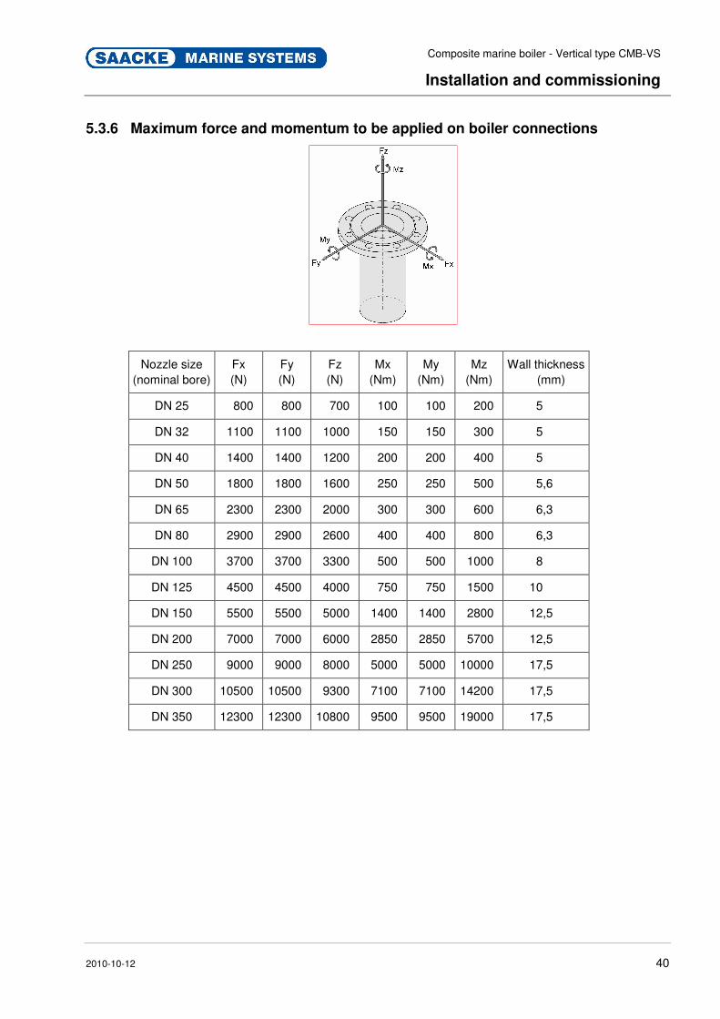
5.3.6 Maximum force and momentum to be applied on boiler connections
Nozzle size (nominal bore)
Fx (N)
Fy (N)
Fz (N)
Mx (Nm)
My (Nm)
Mz (Nm)
Wall thickness (mm)
DN 25 800 800 700 100 100 200 5
DN 32 1100 1100 1000 150 150 300 5
DN 40 1400 1400 1200 200 200 400 5
DN 50 1800 1800 1600 250 250 500 5,6
DN 65 2300 2300 2000 300 300 600 6,3
DN 80 2900 2900 2600 400 400 800 6,3
DN 100 3700 3700 3300 500 500 1000 8
DN 125 4500 4500 4000 750 750 1500 10
DN 150 5500 5500 5000 1400 1400 2800 12,5
DN 200 7000 7000 6000 2850 2850 5700 12,5
DN 250 9000 9000 8000 5000 5000 10000 17,5
DN 300 10500 10500 9300 7100 7100 14200 17,5
DN 350 12300 12300 10800 9500 9500 19000 17,5
Pos : 5.28 /KN 2006-SM /nL.. ... ... .. Sei tenumbr uch .. ... ... .. @ 8\mod_1141998334703_0.doc @ 75491

Composite marine boiler - Vertical type CMB-VS
Installation and commissioning
2010-10-12 41
Pos : 5.29 /KN 2006-SM /Installati on & Inbetriebnahme/007 1.1 Ers tinbetriebnahme_Titel @ 9\mod_1144401802375_2.doc @ 86435
5.4 Commissioning Pos: 5.30 /KN 2006-Pr ojekte/Saacke Mari ne Sys tems/Boiler/ Install ati on & Inbetriebnahme/ 011 1.1.1 Erstinbetriebnahme_T ext_pr einstall ed safety val ves (CM B-VS) @ 103\mod_1286883479753_2.doc @ 1583810
Unless agreed otherwise, initial start-up of the system is carried out by employees of the manufacturer.
Unauthorized initial start-up is not permitted and leads to loss of guarantee.
The system is handed over to the customer following set-up, initial start-up and implementation of test runs by the manufacturer. Then the system can be operated while observing the information in the operating manual.
WARNING!
Danger of injury by misapplication!
Misapplication during Start-up can lead to dangerous situations.
Therefore:
– Start-up must only be carried out by qualified technical personnel while observing the safety instructions.
Heating up curve
Fig. 8: Heating up curve
Composite marine boiler - Vertical type CMB-VS
Installation and commissioning
2010-10-12 42
The following steps are to be taken for initial start-up of the system while observing all safety instructions and the notes in Chapter "Safety":
� Make sure there are no debris in the boiler.
� Check that system including all components is secure.
� Check that technical water is available.
� Check that fuel oil is available.
� Check that all connections are properly installed.
� Check that supply of electric energy is secured.
� Check that water level electrodes are properly adjusted.
� Check and start up the burner/firing system to a state in which safe automatic operation is possible.
� Follow the heating up curve for the first heating of the boiler before applying continuous firing.
� Boil the boiler and the steam/feedwater system out, before it is put into service to remove any foreign matters. For boiling out procedure see Chap. "Feedwater Treatment, Boiling out".
Setting of safety valves
Note!
The safety valves are preinstalled and preset by
Saacke GmbH & Co KG.
In case of any setting of the safety valves contact
Saacke for getting all required information (for
contact dates see page 2.)
Checking safety valve capacity:
1. Shut off pressure switches.
2. Lock the burner in max. position.
3. Close main steam valve.
4. Check that the safety valves together have the capacity to blow off the steam so that the boiler pressure does not exceed design pressure by 10 %. If pressure is rising above that figure, shut off the burner.
NOTE!
For further information on safety valves refer to
"Shut-off valves" in the "Documentation of
Components".
The system can now be operated within the overall system while observing all safety instructions.
Composite marine boiler - Vertical type CMB-VS
Testing and approval procedure
2010-10-12 43
Pos : 6.1 /KN2006- Proj ekte/Saacke M arine Systems/Boil er/Testing and approval procedure/nL.... ... ... Seitenumbr uch . .... ... .. @ 92\mod_1233163009401_0.doc @ 1393398 Pos : 6.2 /KN2006- Proj ekte/Saacke M arine Systems/Boil er/Testing and approval procedure/001 1 T esti ng and approval procedur e_Ti tel (CM B) @ 92\mod_1233077795525_2.doc @ 1392998
6 Testing and approval procedure
After installing and completing the boiler a competent service engineer has to carry out the commissioning of the boiler. Before starting work he has to be ensure, that the boiler is prepared in the way described in the "pre-commissioning checklist". After this initial checks, the burner is to adjust and to put into operation.
The boiler is to prepared for the boiling out procedure. Then the boiler is to warm up according to the heating up curve. This will dehumidify and stabilize the brickwork also. After holding the pressure for the specified time for boiling out, the boiler is to drain and to refill with clean condensate or technical water. The permanent chemical treatment of the boiler water is to perform according to the instructions and dependent on the quality of the used feed water.
After warming up the boiler again and the boiler can be pressurized. At 3 bar there is to check every connection and valve mounted at the boiler. If there are leakages the connections has to tighten, if necessary by changing gaskets after depressurizing the boiler.
When the boiler is pressurized, the boiler safety devices and equipment is to test according to the test program. This test are normally done in attendance of a surveyor from the classification society. This includes testing feed water pumps, oils supply, burner system and combustion air. The tests of the boiler contain testing alarms for high and low pressure, water level alarms, functional test of the safety valves and the safety valves capacity test (accumulation test) for the worst case. The function of the surplus steam dumping equipment will also be tested.
The rest of the test program contains test of boiler operation, burner start, stop and modulating, combustion adjustment and system stability in automatic operation as well as changing to manual operation and reverse. All test results has to write down and will be signed by service engineer, shipyard, surveyor and owners deputy.
A final performance test of the electric control system can be done in addition, depending on the shipyards test and trials schedule.
Pos: 7.1 /KN2006- SM/nL.... ... ... Seitenumbr uch . ... ... ... @ 8\mod_1141998334703_0.doc @ 75491
Composite marine boiler - Vertical type CMB-VS
Operation
2010-10-12 44
Pos : 7.2 /KN2006- SM/Bedienung/001 1 Bedi enung _Titel @ 9\mod_1144402040153_2.doc @ 86491
7 Operation Pos : 7.3 /KN2006- SM/Bedienung/002 1.1 Sicherheit_Titel @ 9\mod_1144402036547_2.doc @ 86456
7.1 Safety Pos : 7.4 /KN2006- Proj ekte/Saacke M arine Systems/Boil er/Bedienung/1.1.0 Gr undleg endes (CMB) @ 91\mod_1232709895568_2.doc @ 1388426
Organizational Measures
WARNING!
Risk of injury due to neglecting basic safety
precautions for operational safety!
Neglecting safety precautions can lead to severe injuries or property damage.
Therefore:
– Plant authorities must ensure, that only autho-rized and qualified personal works on the CMB.
– All safety-related requirements must be met before the plant is started up each time.
– The plant must be ready for operation and in functionally reliable condition.
– Prior to operation, ensure that all covers and safety devices are installed and working properly.
– Keep a clean and orderly working environment! Components and tools loosely stacked or spread about constitute accident hazards.
Safety Precautions during
Operation
WARNING!
Risk of injury due to improper operation!
Improper operation can lead to severe injuries or property damage.
Therefore:
– Refrain from any mode of operation which causes danger to life and limb of the operator or third parties.
– Refrain from any mode of operation which may result in damage to the CMB or other systems.
– Refrain from any mode of operation which compromises the safety and function of the CMB or other systems.
– Refrain from any actions that are contradictory to the safety instructions in this Manual and to those drawn up by the plant authorities.
– Never disable safety devices during operation.
� The operator is responsible for third parties within the working area of the boiler.
Composite marine boiler - Vertical type CMB-VS
Operation
2010-10-12 45
Pos : 7.5 /KN2006- SM/nL---------- Abschnit tsende ---------- @ 8\mod_1141997892953_0.doc @ 75473 Pos : 7.6 /KN2006- Proj ekte/Saacke M arine Systems/Boil er/Bedienung/002 1.1.0 Warnhinweise Bedienung (CMB-VS) @ 91\mod_1232710799121_2.doc @ 1388549
Improper supervising
CAUTION!
Improper supervising can result in damage!
Improper or not at all supervised system functions and operating ranges can lead to malfunctions and material damage.
Therefore:
– System functions and operating ranges are to be supervised regularly by trained supervisory personnel.
Incorrect operation
WARNING!
Danger of injury by incorrect operation!
Incorrect operation can lead to severe injuries or material damage.
Therefore:
– Operation may only be carried out by trained technical staff while observing the safety instructions.
Pos : 7.7 /KN2006- SM/nL---------- Abschnit tsende ---------- @ 8\mod_1141997892953_0.doc @ 75473
Pos: 7.8 /KN2006- Proj ekte/Saacke M arine Systems/Boil er/Bedienung/1.2.0 Besondere Gefahr en: Heiß e M edien (CMB-HF) @ 91\mod_1232710709714_2.doc @ 1388518
Hot Fluids
CAUTION!
Danger of burning by hot fluids!
The system is operated by fluids with high temperatures.
Fluids like steam, water or operating supplies keep their high temperatures though the surface of the boiler has already cooled down. Therefore:
– Always wear protective gloves.
– Before starting any maintenance and repair work wait at least 20 minutes allowing the boiler to cool down and exhaust gases to disperse.
Pos : 7.9 /KN2006- SM/nL---------- Abschnit tsende ---------- @ 8\mod_1141997892953_0.doc @ 75473
Composite marine boiler - Vertical type CMB-VS
Operation
2010-10-12 46
Pos : 7.10 /KN 2006-Pr ojekte/Saacke Mari ne Sys tems/Boiler/Bedi enung/1.2.0 Besonder e Gefahren: M edien unter Dr uck (CM B-HF) @ 91\mod_1232710570682_2.doc @ 1388494
Pressurized media
WARNING!
Danger of injury from pressurized media!
The system is operated with media under pressure.
In case of damage, malfunction or human failure media may escape under high pressure causing severe injury, especially to the eyes. Therefore:
– Never open/loosen/remove boiler components when boiler is pressurized.
– Comply with operating pressure ranges.
– In case of damage to pressure vessel, steam system, directly installed boiler mountings or the exhaust gas section as well as before starting maintenance and repair work, make sure that the system is depressurized.
– When depressurizing be careful not to depressurize the boiler by blowing off the steam through the vent valve or safety valves. Otherwise they will be damaged.
Pos : 7.11 /KN 2006-SM /nL---------- Abschnittsende ---------- @ 8\mod_1141997892953_0.doc @ 75473
Pos: 7.12 /KN 2006-Pr ojekte/Saacke Mari ne Sys tems/Boiler/Bedi enung/1.2.0 Besonder e Gefahren: H eiß e Oberflächen (CMB-HF) @ 91\mod_1232710531666_2.doc @ 1388449
Hot Surfaces
CAUTION!
Danger of burning on hot surfaces!
The insulated surface of the boiler may reach temperatures 20 °C higher than the ambient air temperature 1m from the boiler, the uninsulated surface of the exhaust gas flanges may even reach temperatures up to 420 °C. There is a danger of burning from high temperatures on the surface of the boiler, especially in the area of the exhaust gas section. Therefore:
– Always wear protective gloves.
– Before starting maintenance and repair work, make sure that the surface has cooled down to ambient temperature.
Pos : 7.13 /KN 2006-SM /nL---------- Abschnittsende ---------- @ 8\mod_1141997892953_0.doc @ 75473
Pos: 7.14 /KN 2006-Pr ojekte/Saacke Mari ne Sys tems/Boiler/Bedi enung/002 1.1.0 Persönliche Schutzausr üstung Bedi enung_Text (CMB-VS) @ 91\mod_1232712854274_2.doc @ 1388782
Protective Gear Wear the following protective gear during operation:
� Fireproof protective clothing (Never wear clothes of synthetic fibre in the machine room!)
� Protective gloves
� Safety boots Pos : 7.15 /KN 2006-SM /nL.. ... ... .. Sei tenumbr uch .. ... ... .. @ 8\mod_1141998334703_0.doc @ 75491

Composite marine boiler - Vertical type CMB-VS
Operation
2010-10-12 47
Pos : 7.16 /KN 2006-Pr ojekte/Saacke Mari ne Sys tems/Boiler/Bedi enung/1.1 Tätigkeiten vor Gebr auch (CM B-VS) @ 91\mod_1232713403528_2.doc @ 1388829
7.2 Checks before Start-up
1. Check boiler and fittings for correct application.
2. Fill the boiler with technical water to a quarter of the glass BO 019/020. When filling a pressureless boiler, the shut-off valve after the feed water pump is to be throttled, otherwise the pump motor will be overloaded.
3. Check and confirm that the water level control BO 021/022 is connected and in function.
4. Check the burner and confirm the safety functions.
5. If there is an electrical oil preheater, start the fuel oil circulation pump and heat up the fuel oil to the correct temperature. Otherwise the boiler shall be started with diesel oil and the steam heated oil preheater will be heated when the boiler supplies steam.
Pos : 7.17 /KN 2006-Pr ojekte/Saacke Mari ne Sys tems/Boiler/Bedi enung/1.1 Start-R outi ne (CMB- VS) _Titel @ 92\mod_1232713856921_2.doc @ 1388880
7.3 Start-up routine Pos : 7.18 /KN 2006-Pr ojekte/Saacke Mari ne Sys tems/Boiler/Bedi enung/1.1.0 Start-Routi ne D ampfkr eis (CM B-VS) @ 92\mod_1232714149298_2.doc @ 1388932
Start-up routine for steam cycle 1. Open the venting valve BO 016.
2. Start the burner on manual control and low load.
3. Check that the water level does not rise too high during pressure raising.
4. Drain via the blow-down valves BO 009/010 if the water level is too high.
NOTE!
After 3-4 weeks in operation, mud and deposits in
the piping system may have been accumulated in
the boiler water. This may cause level variations
which disturbs the steam generation.
5. Shut the venting valve BO 016 when the steam blows out.
6. Tighten the manhole/hand hole cover(s) during pressure raising, if required.
7. Check all flange joints at the plant.
8. Change to automatic control when the boiler pressure is 0.5 bar lower than the working pressure of the boiler.
9. Open the main steam valve BO 002 slowly and open also for steam to the fuel oil preheater.
10. Open the valves to the outer steam consumers carefully. Pos : 7.19 /KN 2006-SM /nL.. ... ... .. Sei tenumbr uch .. ... ... .. @ 8\mod_1141998334703_0.doc @ 75491
Composite marine boiler - Vertical type CMB-VS
Operation
2010-10-12 48
Pos : 7.20 /KN 2006-Pr ojekte/Saacke Mari ne Sys tems/Boiler/Bedi enung/1.1 Während des Gebr auchs (CM B)_Titel & Warnhinweise @ 92\mod_1232715406271_2.doc @ 1388954
7.4 During operation (Maintenance on daily basis)
WARNING!
Danger of injury by misapplication!
Misapplication during operation can lead to dangerous situations.
Therefore:
– Always follow the instructions for the plant.
– Comply with operating ranges.
CAUTION!
Risk of material damage!
Misapplication like operation without water can cause material damage.
Therefore:
– Do not operate the boiler without water.
– Do not operate the boiler with oil in the feed water.
Pos : 7.21 /KN 2006-Pr ojekte/Saacke Mari ne Sys tems/Boiler/Bedi enung/1.1 Während des Gebr auchs_Text (CM B-VS) @ 92\mod_1232716044856_2.doc @ 1389306
1. Blow down the boiler. Open blow down valves BO 009. Then open the blow-down valves BO 010 quickly for a few seconds, shut and open again 5-10 seconds. Repeat this 1-3 times each 24 hour or when required according to the boiler water tests.
2. Defoam the boiler. Open the defoaming valve BO 008 for 10-20 seconds. Repeat this 1-3 times each 24 hours.
3. Drain each level glass BO 019/020 for 10-15 seconds.
4. Check the boiler water condition and make necessary countermeasures with regard to the feedwater treatment instructions.
5. Check the function of the burner at different capacities through the flame inspection glass on the boiler. Refer to the Burner Manual for details.
6. Check the fuel oil temperature and pressure. Check the fuel oil flow at a certain load. Refer to Burner Manual for details.
7. With changing the fuel oil quality, check function of the burner carefully. Align it anew. The fuel oil temperature should be set so that the correct viscosity is obtained. Refer to Burner Manual for details.
Composite marine boiler - Vertical type CMB-VS
Operation
2010-10-12 49
8. Check the flue gas temperature after the boiler. If too high, clean the heating surface from soot.
9. Check and clean the flame scanner and the fuel oil filters.
10. Check the boiler steam pressure and the water level.
NOTE!
After 3-4 weeks in operation, mud and deposits
from the piping system can have been
accumulated in the boiler water. This may cause
level variations which disturbs the steam
generation.
11. Check the feedwater control BO 021 according to separate instruction.
12. Is the safety level device BO 022 check due (once a week)?
13. Is the stand-by feedwater pump test due (once a month)?
14. Check the function of the high steam pressure switch BO 034 by setting it down or by raising the steam pressure. The burner shall stop by itself – an alarm shall be generated. If necessary, reset the pressure switch after check.
15. Visually check all valves and fittings mounted to the boiler for leakages.
Pos : 7.22 /KN 2006-SM /nL.. ... ... .. Sei tenumbr uch .. ... ... .. @ 8\mod_1141998334703_0.doc @ 75491
Composite marine boiler - Vertical type CMB-VS
Operation
2010-10-12 50
Pos : 7.23 /KN 2006-Pr ojekte/Saacke Mari ne Sys tems/Boiler/Bedi enung/1.1 Abschalten_Ti tel (CM B) @ 92\mod_1232716895936_2.doc @ 1389348
7.5 Shut-down Pos : 7.24 /KN 2006-Pr ojekte/Saacke Mari ne Sys tems/Boiler/Bedi enung/1.1.1 Abschalten reg ulär _Text (CMB- VS) @ 92\mod_1232717265501_2.doc @ 1389390
7.5.1 Regular shut-down procedure
This procedure is to be applied when the boiler shall be taken out of service for inspection purpose and/or a longer period of time such as extended shipyard stay or lay up period.
1. Clean the boiler from soot by water washing or chemical soot removes injection immediately before final shut-down. Start the burner again and keep it in operation for at least 15 min. after the soot removal to dry out the possible remaining water in the gas chambers.
2. Check the furnace with regard to cleanliness.
3. Empty the boiler from water and clean it. Check if limestone has appeared.
4. Check and clean the outer fittings.
5. Change gaskets where required.
6. Clean feedwater tank and feedwater pipes.
7. Clean and grease the bearings of motor, pump and fan.
8. Check and align the burner.
In case, the fuel oil supply has to be shut down as well, it is necessary to purge the fuel oil supply line with MDO before shutting down. For how to change over from HFO to MDO refer to burner manual.
Pos : 7.25 /KN 2006-SM /nL.. ... ... .. Sei tenumbr uch .. ... ... .. @ 8\mod_1141998334703_0.doc @ 75491

Composite marine boiler - Vertical type CMB-VS
Operation
2010-10-12 51
Pos : 7.26 /KN 2006-Pr ojekte/Saacke Mari ne Sys tems/Boiler/Bedi enung/1.1.1 Langzeit-Abschalten (CM B-VS) @ 92\mod_1232717407002_2.doc @ 1389412
7.5.2 Long-term shut-down
Safety
CAUTION!
Risk of property damage by improper
preservation!
Improper preservation can cause material damage.
Therefore:
The boiler must NOT be depressurized by lifting the safety valves and then filled with water since the stress induced by too rapid cooling may cause damage.
– If the boiler still contains hazardous chemicals, completely drain it and refill it with a fresh supply of water before taking it into service again.
– If the boiler is to be drained off, leave all inspection hatches open when emptying. It is important that the air flow through the boiler is as dry as possible.
As laying up of a ship, the air in the engine room is usually humid and damp. For a perfect preservation use a dehumidificating agent.
Shut-down up to one month 1. Clean the boiler from soot deposits
2. Top fill the boiler to prevent corrosion.
For top filling the boiler, proceed as follows:
a) Close the main steam valve (BO 002).
b) Allow the boiler to cool.
c) Open vent valve (BO 016).
d) Turn feedwater control valve (FW 010) to MANUAL and open valve.
e) Allow boiler to fill until water comes out of the vent valve (BO 016).
f) Close feedwater inlet valves and vent valve (BO 016).
g) Stop feedwater pump (FW 001).
3. Purge the fuel oil supply line with MDO before shutting down. For how to change over from HFO to MDO refer to burner manual.
Composite marine boiler - Vertical type CMB-VS
Operation
2010-10-12 52
Short-term preservation During short term idle periods, one of the following methods of protection, whichever is most convenient, is to be used.
� Completely fill the boiler with alkaline water containing sufficient catalysed sodium sulphite to combine with the dissolved oxygen and leave an excess of 200 ppm Na2SO3. Raise the water to the boiling point to induce mixing by circulation and to complete the chemical reaction before sealing the boiler.
� Completely fill the boiler with alkaline water containing sufficient chemicals to combine with the dissolved oxygen and leave an excess of the chemical, for periods up to three days, the chemical excess should be at least 25 ppm N2BH B4B. Raise the water to the boiling point to induce mixing by circulation and to complete the chemical reaction before sealing the boiler.
When using the above methods, the alkalinity is to be raised to the recommended value by the addition of the appropriate chemical normally used. It is also necessary to check periodically the excess of sulphite or an equivalent chemical in the boiler and to restore any that has been oxidized.
If the boiler is not being emptied then the sodium sulphate or an equivalent chemical must be added a short time before steaming ceases. The treatment, in solution, is to be directly injected into the boiler or added as a single shot at the feed tank, via a tundish fitted with a pipe leading into the feed pump suction.
Wet storage methods are not advised in circumstances in which the water in the boiler or pipe work could freeze during idle periods. All wet storage methods could be completed with connection of a small nitrogen bottle, thus putting the boiler in a very low pressure preventing any oxygen from entering from the open air in case of small leakages.
Also, precautions are to be taken to prevent atmospheric condensation upon the fire-side surfaces of the boiler, which would lead to severe external corrosion.

Composite marine boiler - Vertical type CMB-VS
Operation
2010-10-12 53
Shut-down for more than one
month
There are different methods to prevent corrosion:
A: Top fill (for how to top fill, see above) the boiler and treat the water with a suitable agent.
B: Complete draining of the boiler.
C: Nitrogen treatment (gas).
For alternative A, calculate feedwater dosage to result in 200 ppm of N2H4 or equivalent.
With all 3 methods be sure to purge the fuel oil supply line with MDO before shutting down. For how to change over from HFO to MDO refer to burner manual.
Long-term preservation For long term storage, the following methods are available:
� Use a corrosion inhibitor such as recommended for diesel cooling water treatment. In this case fill the boiler with water correctly treated with the appropriate amount of corrosion inhibitor; a suitable corrosion inhibitor is a mixture of sodium nitrite and borate at a concentration of 1000 to 3000 ppm of each chemical. Keep in mind that the boiler must be drained and washed out to remove these inhibitors before it is prepared for steaming.
� Dry storage Completely empty the boiler, dry it out by gentle heat and then blow in a moisture absorbing and vaporizing powder like Shell VPI and seal the boiler gastight.
� Use cyclohexylamine carbonate, or cyclohexylammonium nitrite.
Treatment of external boiler surfaces for long-term storage:
1. Clean external surfaces thoroughly to remove all the vanadium and sulphate deposits using the appropriate cleaning techniques. Otherwise condensation will produce strong acids and rapid external corrosion of boiler tubes etc.
2. If heat is available to prevent moisture condensing on the metal surfaces then further action may be unnecessary. However, additional insurance is possible by spraying the tubes with a protective film of a film-forming corrosion inhibitor.
3. All valves are to be checked for leakage in spindle glands to prevent corrosion of boiler outside shell.
Pos : 7.27 /KN 2006-SM /nL.. ... ... .. Sei tenumbr uch .. ... ... .. @ 8\mod_1141998334703_0.doc @ 75491
Composite marine boiler - Vertical type CMB-VS
Operation
2010-10-12 54
Pos : 7.28 /KN 2006-Pr ojekte/Saacke Mari ne Sys tems/Boiler/Bedi enung/1.1 Dry runni ng the exhaust g as secti on (CMB-VS) @ 92\mod_1232722060938_2.doc @ 1389444
7.6 Dry running the exhaust gas section under certain conditions
If occurres any damage on the pressure part, or of an extent which is not manageable by temporary repair methods, while the vessel is underway at sea, and the schedule does not allow a longer shut-down of the main engine in order to make temporary repairs, then it becomes inevitable to run the boiler dry., .
Dry running of the boiler is generally possible with actual main engine exhaust gas temperature up to 400 °C. Cleaning of heating surface has to be performed as usual also during dry running period.
CAUTION!
Risk of damage!
Starting the burner while running dry may cause damage to the burner and the boiler.
Therefore:
– Do not start the burner when dry-running the boiler.
To prepare the boiler for dry running, please proceed as follows:
1. Dismount all temperature sensitive devices, such as boiler level controls and limiting devices.
2. Seal control device necks on boiler body with appropriate gaskets and blind flanges.
3. Except drain and vent valve close all valves on the boiler body and secure against unauthorized opening.
NOTE!
Vent valves and drain valves must be kept open.
4. Dismount the burner or switch on the combustion air fan and keep it running for the whole dry running period in order to provide sufficient cooling air to the burner assembly.
CAUTION!
Risk of overheating!
Keeping the combustion air fan off might result in overheating and subsequent damage to the burner equipment due to heat transfer through the boiler body steel structure.
Therefore:
– Keep the combustion air fan on.

Composite marine boiler - Vertical type CMB-VS
Operation
2010-10-12 55
5. Check the heating surface by visual inspection.
6. If there is any pollution by combustible material clean the heating surface.
During dry running period, the heat transfer surface has to be maintained as follows:
CAUTION!
Risk of soot fire!
If the heating surface is not cleaned each time before engine start-up the higher exhaust gas temperature may lead to permanent molten ash deposits or even cause a soot fire.
Therefore:
– Treat the smoke tubes each time before engine starts.
1. Ensure that the heating surface is clean each time before the engine starts up.
When dry running became necessary due to damage to the pressure part the boiler has to undergo permanent repairs as soon as possible in coordination with the classification society involved.
For repair or exchange of smoke tubes on boiler please refer to the boiler body's repair instructions.
When taking the boiler into operation again after permanent repair, proceed as follows:
1. Open control device necks on boiler body by removing the blind flanges.
2. Remount all temperature sensitive devices which have been taken off prior to dry-running period, such as boiler level controls and level limiting devices.
3. Put all valves on the boiler body back into position for normal operation.
4. Check all safety and control functions of the automatic control system.
5. Boil out the boiler according to boiling out instructions.
6. Heat up the boiler slowly to normal operating temperature, applying heat with burner or reduced main engine load.
Pos : 8.1 /KN2006- SM/nL.... ... ... Seitenumbr uch . ... ... ... @ 8\mod_1141998334703_0.doc @ 75491

Composite marine boiler - Vertical type CMB-VS
Malfunctions and Troubleshooting
2010-10-12 56
Pos : 8.2 /KN2006- Proj ekte/Saacke M arine Systems/Boil er/Stör ung en/1 Störungen_Titel+T ext (CMB) @ 92\mod_1232722757458_2.doc @ 1389594
8 Malfunctions and Troubleshooting
The following chapter describes possible causes of faults and the steps required to eliminate them.
� Malfunctions of any kind must be reported immediately to the shift manager and eliminated in accordance with all safety regulations.
WARNING!
Loss of operational safety!
Malfunctions which impair or endanger the functional and operational reliability and safety of the plant itself or the surrounding area pose a risk for the life and health of persons.
Therefore:
– Malfunctions which impair or endanger the functional and operational reliability and safety of the plant are to be eliminated immediately.
� In the event of frequent faults, reduce the maintenance intervals corresponding to the actual working load.
� In the event of faults that cannot be eliminated through the following instructions, please contact the manufacturer.
Pos: 8.3 /KN2006- Proj ekte/Saacke M arine Systems/Boil er/Stör ung en/002 1.1 Sicherheit_Ti tel @ 92\mod_1232723071710_2.doc @ 1389617
8.1 Safety notes Pos: 8.4 /KN2006- SM/Stör ung en/003 1.1.0 Personal --> Standar d --> ggf. anpassen @ 12\mod_1144439649253_2.doc @ 86972
Personnel � The troubleshooting procedures described here can be performed by the operator unless otherwise marked.
� Some work may be performed only by specially trained personnel or by the manufacturer, in which case special notice is given in the description of the individual faults.
� All work on the electrical system must be performed by a qualified electrician.
Pos : 8.5 /KN2006- Proj ekte/Saacke M arine Systems/Boil er/Stör ung en/002 1.1.0 Persönliche Schutzausr üstung Störungsbehebung _Text (CMB- VS) @ 92\mod_1232723143710_2.doc @ 1389708
Protective Gear Wear the following protective gear during troubleshooting:
� Fireproof protective clothing: Never wear clothes of synthetic fibre in the machine room!
� Protective gloves
� Safety boots Pos : 8.6 /F I/. ... .... .. Seitenumbr uch .. ... ... .. @ 0\mod272_2.doc @ 1523
Composite marine boiler - Vertical type CMB-VS
Malfunctions and Troubleshooting
2010-10-12 57
Pos : 8.7 /KN2006- Proj ekte/Saacke M arine Systems/Boil er/Stör ung en/1.2.0 Besonder e Gefahren: H eiß e M edi en (CMB-HF) @ 92\mod_1232723111851_2.doc @ 1389640
Hot Fluids
CAUTION!
Danger of burning by hot fluids!
The system is operated by fluids with high temperatures.
Fluids like steam, water or operating supplies keep their high temperatures though the surface of the boiler has already cooled down. Therefore:
– Always wear protective gloves.
– Before starting any maintenance and repair work wait at least 20 minutes allowing the boiler to cool down and exhaust gases to disperse.
Pos : 8.8 /KN2006- SM/nL---------- Abschnit tsende ---------- @ 8\mod_1141997892953_0.doc @ 75473
Pos: 8.9 /KN2006- Proj ekte/Saacke M arine Systems/Boil er/Stör ung en/1.2.0 Besonder e Gefahren: H eiß e Oberflächen (CMB-HF) @ 92\mod_1232723129757_2.doc @ 1389686
Hot Surfaces
CAUTION!
Danger of burning on hot surfaces!
The insulated surface of the boiler may reach temperatures 20 °C higher than the ambient air temperature 1m from the boiler. The uninsulated surface of the exhaust gas flanges may even reach temperatures up to 420 °C. There is a danger of burning from high temperatures on the surface of the boiler, especially in the area of the exhaust gas section. Therefore:
– Always wear protective gloves.
– Before starting maintenance and repair work, make sure that the surface has cooled down to ambient temperature.
Pos : 8.10 /KN 2006-SM /nL---------- Abschnittsende ---------- @ 8\mod_1141997892953_0.doc @ 75473

Composite marine boiler - Vertical type CMB-VS
Malfunctions and Troubleshooting
2010-10-12 58
Pos : 8.11 /KN 2006-Pr ojekte/Saacke Mari ne Sys tems/Boiler/Störungen/1.2.0 Besondere Gefahr en: M edi en unter Druck (CMB-HF) @ 92\mod_1232723121663_2.doc @ 1389662
Pressurized media
WARNING!
Danger of injury from pressurized media!
The system is operated with media under pressure.
In case of damage, malfunction or human failure media may escape under high pressure causing severe injury, especially to the eyes. Therefore:
– Never open/loosen/remove boiler components when boiler is pressurized.
– Comply with operating pressure ranges.
– In case of damage to pressure vessel, steam system, directly installed boiler mountings or the exhaust gas section as well as before starting maintenance and repair work, make sure that the system is depressurized.
– When depressurizing be careful not to depressurize the boiler by blowing off the steam through the vent valve or safety valves. Otherwise they will be damaged.
Pos : 8.12 /KN 2006-SM /nL---------- Abschnittsende ---------- @ 8\mod_1141997892953_0.doc @ 75473
Pos: 8.13 /KN 2006-Pr ojekte/Saacke Mari ne Sys tems/GCU /Stör ungen/1.1.0 Grundl egendes zur Störungsbehebung @ 37\mod_1177857129175_2.doc @ 455125
Other Preconditions
WARNING!
Improper troubleshooting can result in injury!
Improper troubleshooting procedures can result in severe personal injury or material damage.
Therefore:
– Prior to starting troubleshooting work, ensure that there is sufficient space to work.
– Make sure that the assembly location is clean and well organized. Components that are loosely stacked or lying around can cause accidents.
– If components have been removed, ensure proper assembly, install all mounting elements and comply with screw tightening torques.
Pos : 8.14 /KN 2006-SM /nL---------- Abschnittsende ---------- @ 8\mod_1141997892953_0.doc @ 75473
Pos: 8.15 /KN 2006-Pr ojekte/Saacke Mari ne Sys tems/Boiler/Störungen/003 1.1.0 Ver halten bei Stör ung en (CM B) @ 92\mod_1233155431164_2.doc @ 1393375
In case of faults: The following general rules apply:
1. In the event of faults that pose immediate danger to man or machine, activate the emergency shutoff function immediately.
2. Determine cause of fault.
3. If elimination of the fault requires working in the danger zone, switch off unit and secure against being switched on again.
4. Immediately inform the person in charge.
5. Depending on the type of fault, eliminate the fault or have it eliminated by an authorized specialist.
Pos : 8.16 /FI/.. .... ... . Seitenumbruch ... ... ... . @ 0\mod272_2.doc @ 1523
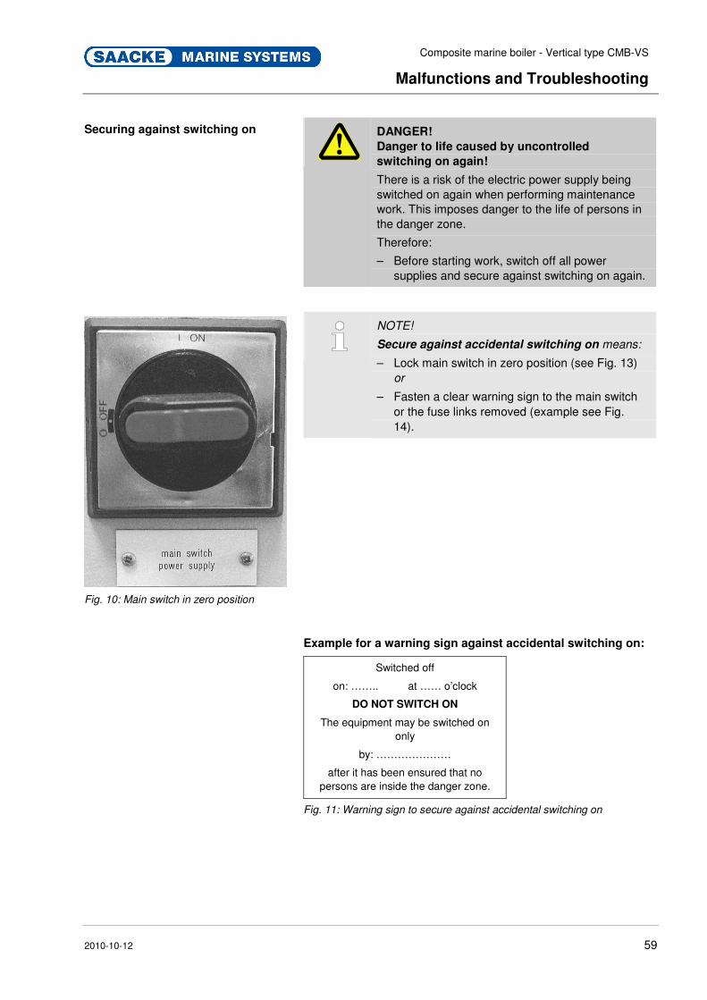
Composite marine boiler - Vertical type CMB-VS
Malfunctions and Troubleshooting
2010-10-12 59
Pos : 8.17 /KN 2006-Pr ojekte/Saacke Mari ne Sys tems/GCU /Wartung/1.1.0 Sicher n gegen Wi ederei nschal ten @ 37\mod_1177849625528_2.doc @ 455083
Securing against switching on
DANGER!
Danger to life caused by uncontrolled
switching on again!
There is a risk of the electric power supply being switched on again when performing maintenance work. This imposes danger to the life of persons in the danger zone.
Therefore:
– Before starting work, switch off all power supplies and secure against switching on again.
Fig. 10: Main switch in zero position
NOTE!
Secure against accidental switching on means:
– Lock main switch in zero position (see Fig. 13) or
– Fasten a clear warning sign to the main switch or the fuse links removed (example see Fig. 14).
Example for a warning sign against accidental switching on:
Switched off
on: …….. at …… o’clock
DO NOT SWITCH ON
The equipment may be switched on only
by: …………………
after it has been ensured that no persons are inside the danger zone.
Fig. 11: Warning sign to secure against accidental switching on
Pos : 8.18 /FI/.. .... ... . Seitenumbruch ... ... ... . @ 0\mod272_2.doc @ 1523

Composite marine boiler - Vertical type CMB-VS
Malfunctions and Troubleshooting
2010-10-12 60
Pos : 8.19 /KN 2006-Pr ojekte/Saacke Mari ne Sys tems/Boiler/Störungen/1.1 Acti on during malfunc tions (CMB- VS) @ 92\mod_1232722527425_2.doc @ 1389730
8.2 Action during malfunctions
WARNING!
Danger of life by misapplication!
Misapplication during operation can lead to dangerous situations.
Therefore:
– All malfunctions may only be remedied by qualified technical personnel.
– Observe the notes in the Chapter "Maintenance" before, during and after work to remedy malfunctions.
1. For malfunctions which present an immediate danger to persons, objects and operational safety of the system stop the overall plant system control by immediately triggering the Emergency stop function.
CAUTION!
Risk of damage from safety feature abuse!
If Safety features are used to shut down the system normally, this might affect the system.
Therefore:
– Only operate Safety features with an Emergency stop function in corresponding emergency situations.
2. Decide whether the system has to be depressurized or not (see below).
3. Limit the damage and take necessary measures to prevent consequential losses.
4. Notify the manufacturer.
5. Authorize the relevant technical personnel to determine the type of malfunction and to remove the cause of the malfunction.
6. Remove the cause of the malfunction as described in the troubleshooting section. For repairs that are not described under "Malfunctions" or "Boiler body", "Permanent repair", immediately contact the service department of the manufacturer.
Pos : 8.20 /FI/.. .... ... . Seitenumbruch ... ... ... . @ 0\mod272_2.doc @ 1523

Composite marine boiler - Vertical type CMB-VS
Malfunctions and Troubleshooting
2010-10-12 61
Pos : 8.21 /KN 2006-Pr ojekte/Saacke Mari ne Sys tems/Boiler/Störungen/1.1.0 Druckabl ass-Fäll e (CMB- VS) @ 92\mod_1232725484178_2.doc @ 1389752
Cases in which to depressurize The system has to be depressurized in case of:
� damage to the pressure vessel,
� damage to the steam system with no possibility to close the main steam valve
� damage to directly installed boiler mountings (e.g. water level gauges)
� damage to the exhaust gas section,
� before starting any repair work.
To depressurize, choose one of the following methods, according to the severity of a damage. The customer is requested to instruct its personnel precisely, which method of depressurizing is suitable for which situation.
If in doubt, choose the faster way of depressurizing.
CAUTION!
Risk of material damage!
Blowing off the steam through the vent valve or the safety valves will damage the valves.
Therefore:
– When depressurizing be careful not to depressurize the boiler by blowing off the steam through the vent valve or the safety valves.
Pos : 8.22 /FI/.. .... ... . Seitenumbruch ... ... ... . @ 0\mod272_2.doc @ 1523
Composite marine boiler - Vertical type CMB-VS
Malfunctions and Troubleshooting
2010-10-12 62
Pos : 8.23 /KN 2006-Pr ojekte/Saacke Mari ne Sys tems/Boiler/Störungen/1.1.0 Schnelles Druckablassen (CMB- VS) @ 92\mod_1232726065651_2.doc @ 1389774
Depressurizing the fast way
WARNING!
Scalding hazard from hot media!
While dry-docked depressurizing the personnel working in the area of the outboard-valve might get severely injured by burns.
Therefore:
– When dry-docked, always make sure before depressurizing, that there is no one working in the area of the outboard-valve.
WARNING!
Risk of permanent hearing damage!
Depressurizing the system the fast way via the blow-down valve produces enormous noise and states a risk to your hearing.
Therefore:
– Wear therefore ear protection before opening the blow-down valve.
CAUTION!
Risk of material damage!
Depressurizing the fast way leads to excessive stress and therefore to advanced fatigue of material since the boiler cools down rapidly.
Therefore:
– If not necessary, depressurize the system gently.
1. Wear ear defenders.
2. Empty boiler via blow-down valve with main steam valve closed.
Pos : 8.24 /FI/.. .... ... . Seitenumbruch ... ... ... . @ 0\mod272_2.doc @ 1523
Composite marine boiler - Vertical type CMB-VS
Malfunctions and Troubleshooting
2010-10-12 63
Pos : 8.25 /KN 2006-Pr ojekte/Saacke Mari ne Sys tems/Boiler/Störungen/1.1.0 Schonendes Druckablassen (CMB- VS) @ 92\mod_1232726804124_2.doc @ 1389796
Depressurizing the gentle way
WARNING!
Scalding hazard from hot media!
While dry-docked depressurizing the personnel working in the area of the outboard-valve might get severely injured by burns.
Therefore:
– When dry-docked, always make sure before depressurizing, that there is no one working in the area of the outboard-valve.
1. Supply cold water to the boiler.
2. Discharge heated water step-by-step via blow-down.
NOTE!
This way of depressurizing is recommended since
the boiler vessel can cool down slowly and
smoothly. Pos : 8.26 /FI/.. .... ... . Seitenumbruch ... ... ... . @ 0\mod272_2.doc @ 1523
Composite marine boiler - Vertical type CMB-VS
Malfunctions and Troubleshooting
2010-10-12 64
Pos : 8.27 /KN 2006-Pr ojekte/Saacke Mari ne Sys tems/Boiler/Störungen/1.1.0 Boil er kompl ett entl eer en (CMB-VS) @ 92\mod_1232727321846_2.doc @ 1389818
Draining off the boiler completely
The boiler has to be drained off completely,
� if the boiler body has to be inspected or repaired from inside and the boiler must therefore be entered by service personnel.
To drain off the boiler completely, proceed as follows:
WARNING!
Scalding hazard from hot media!
While dry-docked depressurizing the personnel working in the area of the outboard-valve might get severely injured by burns.
Therefore:
– When dry-docked, always make sure before depressurizing, that there is no one working in the area of the outboard-valve.
1. Wear ear defenders.
NOTE!
For how to depressurize see "Depressurizing the
gentle way" above.
2. Depressurize the system.
CAUTION!
Risk of material damage!
Material can be damaged by pressure.
Therefore:
– Only use hoses that are laid out for this pressure.
– The connection to the counter flange/screw connection to the vent valve has to be pressure proof.
3. Connect a compressed-air hose to the vent valve. Do not yet supply pressure.
4. Open blow down.
WARNING!
Explosion hazard!
Supplying the compressed-air hose with starting air pressure might burst the boiler.
Therefore:
– Only use working air.
5. Supply compressed-air hose with compressed working air. Pressure range approx. 5 to 7 bar (g).
Pos : 8.28 /FI/.. .... ... . Seitenumbruch ... ... ... . @ 0\mod272_2.doc @ 1523

Composite marine boiler - Vertical type CMB-VS
Malfunctions and Troubleshooting
2010-10-12 65
Pos : 8.29 /KN 2006-Pr ojekte/Saacke Mari ne Sys tems/Boiler/Störungen/1.1 Störungsbehebung_Titel @ 92\mod_1232728225462_2.doc @ 1389840
8.3 Troubleshooting Pos : 8.30 /KN 2006-Pr ojekte/Saacke Mari ne Sys tems/Boiler/Störungen/1.1. Störungsbehebung_Text (CMB- VS) @ 92\mod_1232728298259_2.doc @ 1389862
WARNING!
Danger of injury by incorrect troubleshooting!
Incorrect troubleshooting may lead to severe injuries and property damage.
Therefore:
– Malfunctions may only be remedied by qualified technical personnel. This particularly applies for malfunctions of electrical appliances and for those which affect the areas of mechanics, pneumatics and hydraulics.
For malfunctions that are not included in this table contact the manufacturer.
Problem Recommended action
Manhole cover/ Handhole cover leaking
� Retighten the manhole cover bolts.
� If the gasket is still in acceptable condition, the leaking should stop after few degrees of tigthening, otherwise replace the gasket.
Level gauge glasses leaking
� Depressurize and cool down the boiler to an acceptable level.
� Then remove and check the level gauge glasses and packings, replace the gaskets by new ones and in case of erosion marks on the glass, also replace the glass by a new one.
Level gauge cock leaking
� Depressurize and cool down the boiler to an acceptable level.
� Then replace the special sealings by new ones.
Irregular loss of feed water/ condensate
� Check setting and condition of safety valves, if necessary, increase set pressure within the allowable limits or replace the valve with a new/repaired one.
� Check position and condition of blow down valves, if necessary repair or replace damaged valves.
� Check Manhole/Handhole doors for leakages, if necessary retighten or replace the gaskets.
Low level alarm/ High level alarm (not matching the level gauge mark)
� Check position of level indicator shut-off valves, if partly closed, bring the valves back to fully opened position.
� Check setting of limit switch for transmitter electrode, restore proper alarm level if necessary.
� Check range alignment of 4...20 mA signal, if necessary, realign the instruments according to instructions.
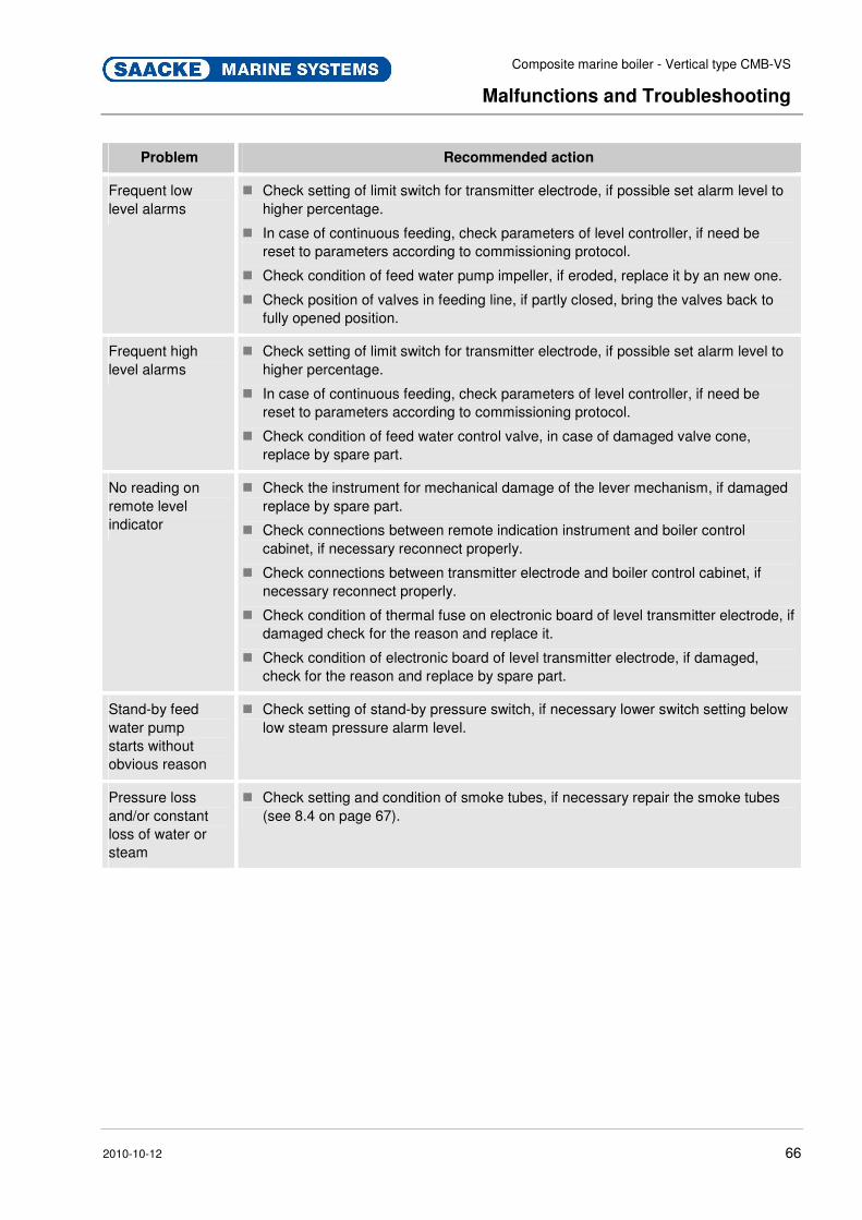
Composite marine boiler - Vertical type CMB-VS
Malfunctions and Troubleshooting
2010-10-12 66
Problem Recommended action
Frequent low level alarms
� Check setting of limit switch for transmitter electrode, if possible set alarm level to higher percentage.
� In case of continuous feeding, check parameters of level controller, if need be reset to parameters according to commissioning protocol.
� Check condition of feed water pump impeller, if eroded, replace it by an new one.
� Check position of valves in feeding line, if partly closed, bring the valves back to fully opened position.
Frequent high level alarms
� Check setting of limit switch for transmitter electrode, if possible set alarm level to higher percentage.
� In case of continuous feeding, check parameters of level controller, if need be reset to parameters according to commissioning protocol.
� Check condition of feed water control valve, in case of damaged valve cone, replace by spare part.
No reading on remote level indicator
� Check the instrument for mechanical damage of the lever mechanism, if damaged replace by spare part.
� Check connections between remote indication instrument and boiler control cabinet, if necessary reconnect properly.
� Check connections between transmitter electrode and boiler control cabinet, if necessary reconnect properly.
� Check condition of thermal fuse on electronic board of level transmitter electrode, if damaged check for the reason and replace it.
� Check condition of electronic board of level transmitter electrode, if damaged, check for the reason and replace by spare part.
Stand-by feed water pump starts without obvious reason
� Check setting of stand-by pressure switch, if necessary lower switch setting below low steam pressure alarm level.
Pressure loss and/or constant loss of water or steam
� Check setting and condition of smoke tubes, if necessary repair the smoke tubes (see 8.4 on page 67).
Pos : 8.31 /FI/.. .... ... . Seitenumbruch ... ... ... . @ 0\mod272_2.doc @ 1523
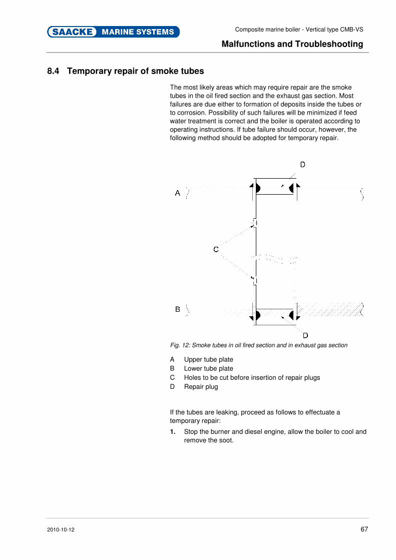
Composite marine boiler - Vertical type CMB-VS
Malfunctions and Troubleshooting
2010-10-12 67
Pos : 8.32 /KN 2006-Pr ojekte/Saacke Mari ne Sys tems/Boiler/Störungen/1.1 Temporar y repair of smoke tube (CMB- VS) @ 92\mod_1232729127514_2.doc @ 1389884
8.4 Temporary repair of smoke tubes
The most likely areas which may require repair are the smoke tubes in the oil fired section and the exhaust gas section. Most failures are due either to formation of deposits inside the tubes or to corrosion. Possibility of such failures will be minimized if feed water treatment is correct and the boiler is operated according to operating instructions. If tube failure should occur, however, the following method should be adopted for temporary repair.
Fig. 12: Smoke tubes in oil fired section and in exhaust gas section
A Upper tube plate B Lower tube plate C Holes to be cut before insertion of repair plugs D Repair plug
If the tubes are leaking, proceed as follows to effectuate a temporary repair:
1. Stop the burner and diesel engine, allow the boiler to cool and remove the soot.

Composite marine boiler - Vertical type CMB-VS
Malfunctions and Troubleshooting
2010-10-12 68
WARNING!
Scalding hazard from hot media!
While dry-docked depressurizing the personnel working in the area of the outboard-valve might get severely injured by burns.
Therefore:
– When dry-docked, always make sure before depressurizing, that there is no one working in the area of the outboard-valve.
2. Depressurize the boiler by depressurizing it the gentle way (see "Depressurizing the gentle way" in this chapter).
3. Enter the boiler gas chamber and cut a hole (C) in the back side of the relevant tube.
4. Clean the rim of the tube with a wire brush.
5. Select tube plug (D) from boiler spare parts box.
6. Fit the plug into the top of the tube and weld it in position as shown.
7. Enter the firebox through the burner opening for tube repair in the oil fired section and the inlet gas box for tube repair in the exhaust gas section. Cut a similar hole in this end of the relevant tube as shown.
8. Repeat operation (4) to (6) for the other end plate.
9. Refill the boiler and check for leaks before starting up.
10. Start the boiler and check for leaks when pressurized.
CAUTION!
Risk of damage!
Improper repair of smoke tubes may cause damage to material.
Therefore:
– A permanent repair shall be made as soon as possible but at the latest, if more than 10 % of the tubes are plugged. If tubes are repaired in this manner, the evaporation rate of the boiler must also be proportionally reduced.
For permanent repair procedures please contact boiler maker. Pos : 9.1 /KN2006- SM/nL.... ... ... Seitenumbr uch . ... ... ... @ 8\mod_1141998334703_0.doc @ 75491

Composite marine boiler - Vertical type CMB-VS
Maintenance
2010-10-12 69
Pos : 9.2 /KN2006- SM/War tung/001 1 Wartung_Titel @ 9\mod_1144434830143_2.doc @ 86797
9 Maintenance Pos : 9.3 /KN2006- Proj ekte/Saacke M arine Systems/Boil er/Wartung/002 1.1 Sicherheit_Ti tel @ 92\mod_1232732306285_2.doc @ 1389954
9.1 Safety Pos: 9.4 /KN2006-Projekte/Saacke Marine Systems/Boiler/Wartung/1.1.0 Personal (CBM) @ 92\mod_1232730705306_2.doc @ 1389931
Personnel � Maintenance and inspection may only be carried out by qualified, specially trained and authorized persons who are also familiar with the hazards that exist while the plant is running, safety devices are dismantled, etc.
� The specialized personnel must be familiar with the special features of the plant and with the relevant occupational safety and other safety regulations.
� The specialized personnel must be informed about where the emergency stop switches are located.
� All work on the electrical equipment should only be executed by a qualified electrician.
NOTE!
Directives valid for firing plants require the operator
to have his plant inspected by a service engineer
of the manufacturer or another skilled person once
a year.
We therefore recommend you to sign a service
contract with the SAACKE Service GmbH. Pos : 9.5 /KN2006- SM/nL---------- Abschnit tsende ---------- @ 8\mod_1141997892953_0.doc @ 75473
Pos: 9.6 /KN2006- Proj ekte/Saacke M arine Systems/Boil er/Wartung/002 1.1.0 Persönliche Schutzausr üstung Wartung _Text (CM B) @ 92\mod_1232732640380_2.doc @ 1390006
Protective Gear The following protective equipment must be worn by the personnel carrying out maintenance/repair work on the system:
� Protective gloves
� Safety shoes
� Heavy fireproof protective clothing
� Face protection
� Ear protection
� Protective goggles Pos : 9.7 /KN2006- SM/nL---------- Abschnit tsende ---------- @ 8\mod_1141997892953_0.doc @ 75473

Composite marine boiler - Vertical type CMB-VS
Maintenance
2010-10-12 70
Pos : 9.8 /KN2006- Proj ekte/Saacke M arine Systems/Boil er/Stör ung en/1.1 Warnhinweise (CMB- VS) @ 92\mod_1232733624199_2.doc @ 1390074
Running system
WARNING!
Danger to Life from running system!
If work is carried out on the system when the system itself and the overall plant system control have not been shut-down, there is a danger of serious injury or even death.
Therefore:
– Before doing any kind of work, shut-down the system and the overall plant system control and secure against switching on again.
– Observe the shut-down procedures described in the operating manual and the necessary safety measures stated therein.
– Whenever operation is interrupted, make sure that all necessary protective features are functioning.
– Observe all measures to be taken after maintenance/assembly work.
Electric current
DANGER!
Danger to life caused by electric current!
Damage to insulations or to protective coverings can cause danger to life. Touching conductive parts poses a direct danger to life. Therefore:
Therefore:
– In the event of damage to insulation switch off the power supply immediately and have the defective parts repaired.
– Work on the electric system must be carried out only by skilled electricians.
– Before maintenance, cleaning or repair work, switch off the power supply and secure it against being switched on again.
– Do not bridge fuses or make them ineffective. When changing fuses make sure you use the correct amperage.
– Keep moisture away from conductive parts. This can cause short circuit.
Composite marine boiler - Vertical type CMB-VS
Maintenance
2010-10-12 71
Unauthorized repair work
WARNING!
Danger of injury and material damage!
Unauthorized repair work state a safety risk.
Therefore:
– Do not conduct repair work not described in the documentation or without explicit authorization of the manufacturer.
– For any kind of repair work see chapter "Documentation of Components" or contact the manufacturer.
NOTE!
Unauthorized repair work leads to a loss of any
claims to compensation. Pos : 9.9 /KN2006- SM/nL---------- Abschnit tsende ---------- @ 8\mod_1141997892953_0.doc @ 75473
Pos: 9.10 /KN 2006-Pr ojekte/Saacke Mari ne Sys tems/GCU /Sicher heit/1.2.0 Besondere Gefahr en: Medi en unter Druck @ 37\mod_1177755200989_2.doc @ 454780
Pressurized media
WARNING!
Danger of injury from pressurized media!
The system is operated with media under pressure.
In case of damage, malfunction or human failure media may escape under high pressure causing severe injury, especially to the eyes.
Therefore:
– Have work on components containing pressurized media only carried out by expert personnel.
– Shut off the plant and secure it against switching on.
– Depressurize pressurized trains before starting any maintenance or repair work.
– Never exceed specified maximum pressure values.

Composite marine boiler - Vertical type CMB-VS
Maintenance
2010-10-12 72
Pos : 9.11 /KN 2006-SM /nL---------- Abschnittsende ---------- @ 8\mod_1141997892953_0.doc @ 75473 Pos : 9.12 /KN 2006-Pr ojekte/Saacke Mari ne Sys tems/Boiler/Wartung/1.2.0 Besondere Gefahr en: H eiße Medien (CM B-HF) @ 92\mod_1232732834944_2.doc @ 1390030
Hot Fluids
CAUTION!
Danger of burning by hot fluids!
The system is operated by fluids with high temperatures.
Fluids like steam, water or operating supplies keep their high temperatures though the surface of the boiler has already cooled down. Therefore:
– Always wear protective gloves.
– Before starting any maintenance and repair work wait at least 20 minutes allowing the boiler to cool down and exhaust gases to disperse.
Pos : 9.13 /KN 2006-SM /nL---------- Abschnittsende ---------- @ 8\mod_1141997892953_0.doc @ 75473
Pos: 9.14 /KN 2006-Pr ojekte/Saacke Mari ne Sys tems/GCU /Sicher heit/1.2.0 Besondere Gefahr en: H eiße Oberfl ächen @ 37\mod_1177752485124_2.doc @ 454754
Hot Surfaces
CAUTION!
Danger of burning on hot surfaces!
Contact with hot components can cause severe burns.
Therefore:
– Do not remove protective coverings, shields or insulation during operation.
– Always wear protective clothes and protective gloves when working on hot components.
– Before starting work make sure that all components have cooled down to ambient temperature.
Pos : 9.15 /KN 2006-SM /nL---------- Abschnittsende ---------- @ 8\mod_1141997892953_0.doc @ 75473
Pos: 9.16 /KN 2006-Pr ojekte/Saacke Mari ne Sys tems/Boiler/Wartung/1.2.0 Besondere Gefahr en: C hemische Substanzen (CM B-HF) @ 92\mod_1232735300069_2.doc @ 1390139
Warning!
Danger of chemical burns!
There is a danger of chemical burns when handling chemicals or liquids containing chemicals. Therefore:
– Always handle chemicals or liquids containing chemicals with care.
– Always wear protective gloves and goggles. Pos : 9.17 /KN 2006-SM /nL---------- Abschnittsende ---------- @ 8\mod_1141997892953_0.doc @ 75473

Composite marine boiler - Vertical type CMB-VS
Maintenance
2010-10-12 73
Pos : 9.18 /KN 2006-Pr ojekte/Saacke Mari ne Sys tems/GCU /Wartung/1.1.0 Grundl egendes zur Wartung @ 37\mod_1177853970074_2.doc @ 455111
Other Preconditions
WARNING!
Injury hazard posed by improperly executed
maintenance work!
Improper maintenance can cause severe injury or property damage. Therefore:
– Prior to starting work ensure that there is sufficient assembly space.
– Ensure order and cleanliness at the assembly site! Loose parts and tools, parts and tools placed on top of each other are hazard sources.
– If components have been removed, ensure that they are properly mounted; re-install all mounting elements and comply with all screw tightening torque specifications.
Pos: 9.19 /KN 2006-SM /nL.. ... ... .. Sei tenumbr uch .. ... ... .. @ 8\mod_1141998334703_0.doc @ 75491 Pos : 9.20 /KN 2006-Pr ojekte/Saacke Mari ne Sys tems/GCU /Wartung/1.1.0 Sicher n gegen Wi ederei nschal ten @ 37\mod_1177849625528_2.doc @ 455083
Securing against switching on
DANGER!
Danger to life caused by uncontrolled
switching on again!
There is a risk of the electric power supply being switched on again when performing maintenance work. This imposes danger to the life of persons in the danger zone.
Therefore:
– Before starting work, switch off all power supplies and secure against switching on again.
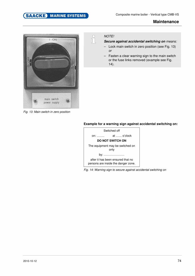
Composite marine boiler - Vertical type CMB-VS
Maintenance
2010-10-12 74
Fig. 13: Main switch in zero position
NOTE!
Secure against accidental switching on means:
– Lock main switch in zero position (see Fig. 13) or
– Fasten a clear warning sign to the main switch or the fuse links removed (example see Fig. 14).
Example for a warning sign against accidental switching on:
Switched off
on: …….. at …… o’clock
DO NOT SWITCH ON
The equipment may be switched on only
by: …………………
after it has been ensured that no persons are inside the danger zone.
Fig. 14: Warning sign to secure against accidental switching on
Pos : 9.21 /KN 2006-SM /nL.. ... ... .. Sei tenumbr uch .. ... ... .. @ 8\mod_1141998334703_0.doc @ 75491
Composite marine boiler - Vertical type CMB-VS
Maintenance
2010-10-12 75
Pos : 9.22 /KN 2006-Pr ojekte/Saacke Mari ne Sys tems/Boiler/Wartung/1.1 Wartungs- und Inspektionsplan (CM B-VS) @ 92\mod_1232734760144_2.doc @ 1390116
9.2 Maintenance and inspection chart
WARNING!
Safety risks and material damage from
neglection of maintenance work!
Neglection of maintenance work and inspection intervalls has negative effects on safety and reduces boiler lifetime.
Therefore:
– Conduct maintenance and inspection work as frequent and in the way as described hereafter.
– Comply with all relevant safety notes.
– Observe maintenance and inspection instructions in the documentation of the components (see "Documentation of Components").

Composite marine boiler - Vertical type CMB-VS
Maintenance
2010-10-12 76
Interval Maintenance work Comments
daily For maintenance work on daily basis see section "During operation".
Check stand-by function of feed water pump.
Recommended in the context of inspections during operation.
Check brickwork by making a photo and comparing with the photo made 3 months before
Check level devices (BO 021/022) Recommended in the context of inspections during operation.
Check set points for pressure and level
Recommended in the context of inspections during operation.
Check pressure switch BO 034 (Steam pressure high)
Recommended in the context of inspections during operation.
monthly
Check valves rarely used by moving
Recommended in the context of inspections during operation.
Check safety valves Recommended in the context of inspections during operation.
Inspect furnace for cracks and deposits. Clean if necessary.
See section "Inspection of the boiler" in this chapter.
Clean tubes by washing with water See section "Soot cleaning" in this chapter.
Inspect interior of the boiler (waterside) for cracks, corrosion and deposits. Clean if necessary.
See section "Inspection of the boiler" in this chapter.
every 6 months
Inspect Boiler foundation for cracks.
As required (at least every 5 years)
Renew damaged brickwork of boiler inlet.
Pos : 9.23 /KN 2006-SM /nL.. ... ... .. Sei tenumbr uch .. ... ... .. @ 8\mod_1141998334703_0.doc @ 75491

Composite marine boiler - Vertical type CMB-VS
Maintenance
2010-10-12 77
Pos : 9.24 /KN 2006-Pr ojekte/Saacke Mari ne Sys tems/Boiler/Wartung/1.1.1 Inspektion des Boil ers (CBM- VS) @ 92\mod_1232735622275_2.doc @ 1390184
9.2.1 Inspection of the boiler
Procedure and remarks for internal
inspection
1. Shut off the boiler and allow it to cool (below 100 °C).
WARNING!
Scalding hazard from hot media!
There is a danger of burning from high temperatures in the boiler, especially in the area of the burner and the exhaust gas section.
Therefore:
– Always wear protective gloves.
– Before starting any maintenance and repair work wait at least 20 minutes allowing the boiler to cool down and exhaust gases to disperse.
2. Empty the boiler and close all valves. If the boiler is connected to a second boiler, check that the valves between them are closed and that non-return valves are not leaking.
3. Unscrew and remove the manhole hatch on pressure vessel and mud hole covers on the lower part of the pressure vessel.
4. Enter pressure vessel and inspect the smoke tubes with the aid of hand lamp.
NOTE!
It is easier to see potential cracks when the tubes
are warm and the cracks are still wet. Hard
deposits on the furnace wall reduce the heat
transfer properties and decrease the boiler
capacity. Appropriate inspection point is the tube
plate top of the furnace.
5. While inspecting the boiler bottom, look for deposits or mud. The presence of mud indicates that the blow-down has been insufficient.
6. Check the longitudinal and circumferential seams in the pressure vessel and the furnace for possible corrosion or crack formation. Also check the welds where the furnace is welded to the end plates.
Composite marine boiler - Vertical type CMB-VS
Maintenance
2010-10-12 78
CAUTION!
Risk of material damage by Incorrect feedwater
treatment!
Incorrect feedwater treatment may under certain conditions cause corrosion. If not corrected in time, this may lead to failure of material.
Therefore:
– Make sure the feedwater treatment is done correctly.
7. Inspect the water line area in the pressure vessel where oxygen pitting may occur. (Under normal operating conditions, or while the boiler is shut down, no oxygen corrosion will occur. However, in case of improper distribution of feedwater or deaeration of the feedwater the risk of this type of corrosion is imminent.)
8. Clean the boiler chemically, if deposits are found in the boiler waterside.
NOTE!
Cleaning work is to be done by specialists!
To prevent faulty cleaning, we advise to consult a
company of cleaning specialists who will examine the
deposits and treat the boiler accordingly.
9. After chemical treatment, the boiler has to be blown down at least twice a day for approximately one week. This will ensure that excessive sludge deposits due to chemical treatment does not collect inside the boiler.
Furnace inspection (at least every 6
month):
1. Check for cracks at the refractory around the burner and that the furnace wall is free from excessive soot deposits.
2. 2Examine carefully the area opposite the burner. Too much soot deposits indicate that burner flame is too long and therefore has to be adjusted.
3. Examine the brickwork at the furnace bottom.
4. Inspect the furnace wall for cracks, especially at the furnace crown tube plate around the tube inlets.

Composite marine boiler - Vertical type CMB-VS
Maintenance
2010-10-12 79
Procedure and remarks for furnace
inspection
Missing brickwork has to replaced immediately. Please note that small cracks in brickework are common and not provoke repairs as long as there is no radiation trough up to the steel walls.
If there are any cracks at the furnace walls it is to suspect that at the water side are deposits which obstruct the heat transfer. In this case a waterside inspection is mandatory.
Inspection of the boiler
water/steam space (at least every
2,5 years):
1. Carefully inspect the boiler water side, examining all parts and being attentive to deposits, corrosion and cracks. It is advisable to spend a long time for this inspection.
2. If any unusual signs are found, contact SAACKE at once for advice.
NOTE!
This is the most important of all maintenance
measures, since it has a direct influence partly on
boiler lifetime and partly on safety.
WARNING!
Safety risks and material damage from
neglection of maintenance work!
If hard deposits have not been removed, it may lead to overheating in the pressure vessel plate material exposed to the flame.
Therefore:
– Therefore always be attentive to deposits during inspections.
At both inspections, hard deposits, corrosion and circulation disturbances can be found at an early stage, and preventive measures can be taken to avoid unexpected material damage and
boiler breakdown. Further, it can be found out if the feed water treatment has been satisfactorily and if the blow-down has been carried out sufficiently. Incorrect feed water treatment is commonly causing hard deposits or corrosion. Insufficient blow-down will cause sludge deposits in the tubes and accumulation of sludge in the boiler bottom and on the top of furnace (See section “Feed water treatment”).
NOTE!
Incorrect feedwater treatment does not always
lead to hard deposits. For example, a too low pH-
value may cause an electrolytic reaction, corroding
the boiler. Pos : 9.25 /KN 2006-SM /nL.. ... ... .. Sei tenumbr uch .. ... ... .. @ 8\mod_1141998334703_0.doc @ 75491

Composite marine boiler - Vertical type CMB-VS
Maintenance
2010-10-12 80
Pos : 9.26 /KN 2006-Pr ojekte/Saacke Mari ne Sys tems/Boiler/Wartung/1.1.1 Soot cleani ng (CMB- VS) @ 92\mod_1233054036829_2.doc @ 1391923
9.2.2 Soot cleaning
After a certain time in operation, soot deposits are accumulated inside the boiler. The frequency of soot cleaning varies from one boiler to another and cannot be specified exactly, depending on factors such as oil quality, boiler load and how the burner is adjusted. However, the following applies:
There are 5 methods to check if
soot cleaning is necessary:
1. In the course of inspection.
2. Checking the exhaust gas temperature of the oil fired part. (Clean if 25 °K above figure for a clean boiler.)
3. Checking the draught loss of the oil fired part. (Clean, if 25 mm water column (WC) above figures for a clean boiler.)
4. For exhaust gas part: Checking whether outlet temperature > 10–15 °C higher than the initial value. (If yes, clean from soots.)
5. For exhaust gas part: Checking whether �p > 25 mm WC from nominal value. (If yes, clean from soots.)
Procedure for soot removal by
water washing
1. Stop the diesel engine and shut off the burner.
2. Unlock burner unit and swing it out of the furnace, see burner manual for details.
3. Wait until exhaust gases are dispersed. The boiler should not cool down before water washing. The best effect of water washing will be gain as long as the boiler is still warm.
4. Open soot water drain valve and check piping not choked. The valve for the oil fired part is located below the furnace (pos. 12 in fig. 3). For the exhaust gas section the drain is at the surge chamber below the boiler.
5. Unlock and remove the flue box inspection hatches located in the upper gas chamber (pos. 1, 18 in fig. 4).
6. When washing oil fired part the burner opening is to cover by a temporary hatch or tarp. Don't swivel in burner without protecting from washing water by a tarp.
7. Using a hand water lance, direct a jet of fresh water directly at each of the vertical smoke tubes. Flush carefully over the smoke tubes with a flow of approx. 50 l/min. Water pressure should be between 4 and 6 bar.
8. Allow time for water to drain and check that soot water is draining from the inlet gas box plus that drain outlet has not become choked.

Composite marine boiler - Vertical type CMB-VS
Maintenance
2010-10-12 81
9. If necessary repeat step 5 and 6.
10. By looking into the inlet gas box through the inspection hole, ensure that all soot water is drained away. Close soot water drain valve.
11. Put back inspection hatches on flue gas box and secure.12.
Start the diesel engine or burner to dry the heating surface.
NOTE!
It is essential that the boiler is dried out in this
manner since soot formations produced by a diesel
engine contains sulphur compounds. Any residual
soot and water will therefore react chemically to
form sulphuric acid, which is highly corrosive.
13. Close the soot water valve. Check that the exhaust gas and flue gastemperature is now within correct limits.
14. Check that all inspection hatches are clamped as tightly as possible and that no gas leaks have occurred. If a hatch is suspected of leaking, replace the gasket.
The most effective but also most time consuming way of soot cleaning is tube brushing (see below). Therefore tube brushing should only be applied, if necessary.
To brush tubes in the oil fired
section, proceed as follows:
1. Stop the diesel engine.
2. Shut off burner.
3. Wait for boiler to cool down to a temperature of at most 100 °C and exhaust gases to disperse until the boiler is completely depressurised.
WARNING!
Scalding hazard from hot media!
There is a danger of burning from high temperatures in the boiler, especially in the area of the burner and the exhaust gas section.
Therefore:
– Always wear protective gloves.
– Before starting any maintenance and repair work wait at least 20 minutes allowing the boiler to cool down and exhaust gases to disperse.
4. Unlock burner unit and swing it out of the furnace, see burner manual for details.
5. Unlock and remove the inspection door at the top of the boiler (pos. 18 in fig.4).
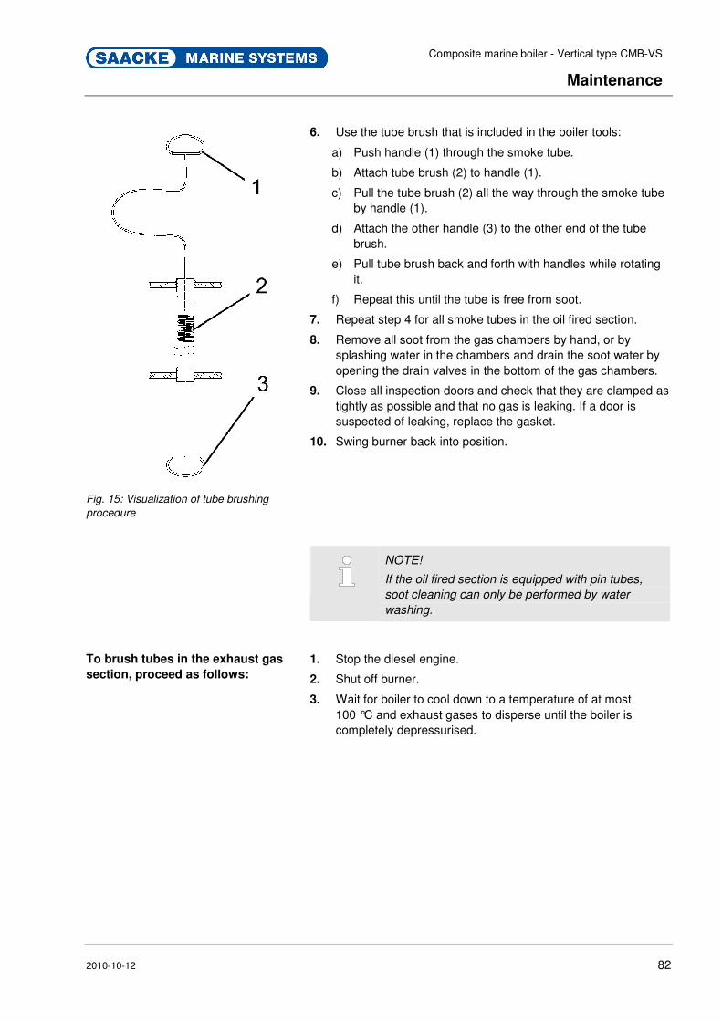
Composite marine boiler - Vertical type CMB-VS
Maintenance
2010-10-12 82
Fig. 15: Visualization of tube brushing
procedure
6. Use the tube brush that is included in the boiler tools:
a) Push handle (1) through the smoke tube.
b) Attach tube brush (2) to handle (1).
c) Pull the tube brush (2) all the way through the smoke tube by handle (1).
d) Attach the other handle (3) to the other end of the tube brush.
e) Pull tube brush back and forth with handles while rotating it.
f) Repeat this until the tube is free from soot.
7. Repeat step 4 for all smoke tubes in the oil fired section.
8. Remove all soot from the gas chambers by hand, or by splashing water in the chambers and drain the soot water by opening the drain valves in the bottom of the gas chambers.
9. Close all inspection doors and check that they are clamped as tightly as possible and that no gas is leaking. If a door is suspected of leaking, replace the gasket.
10. Swing burner back into position.
NOTE!
If the oil fired section is equipped with pin tubes,
soot cleaning can only be performed by water
washing.
To brush tubes in the exhaust gas
section, proceed as follows:
1. Stop the diesel engine.
2. Shut off burner.
3. Wait for boiler to cool down to a temperature of at most 100 °C and exhaust gases to disperse until the boiler is completely depressurised.
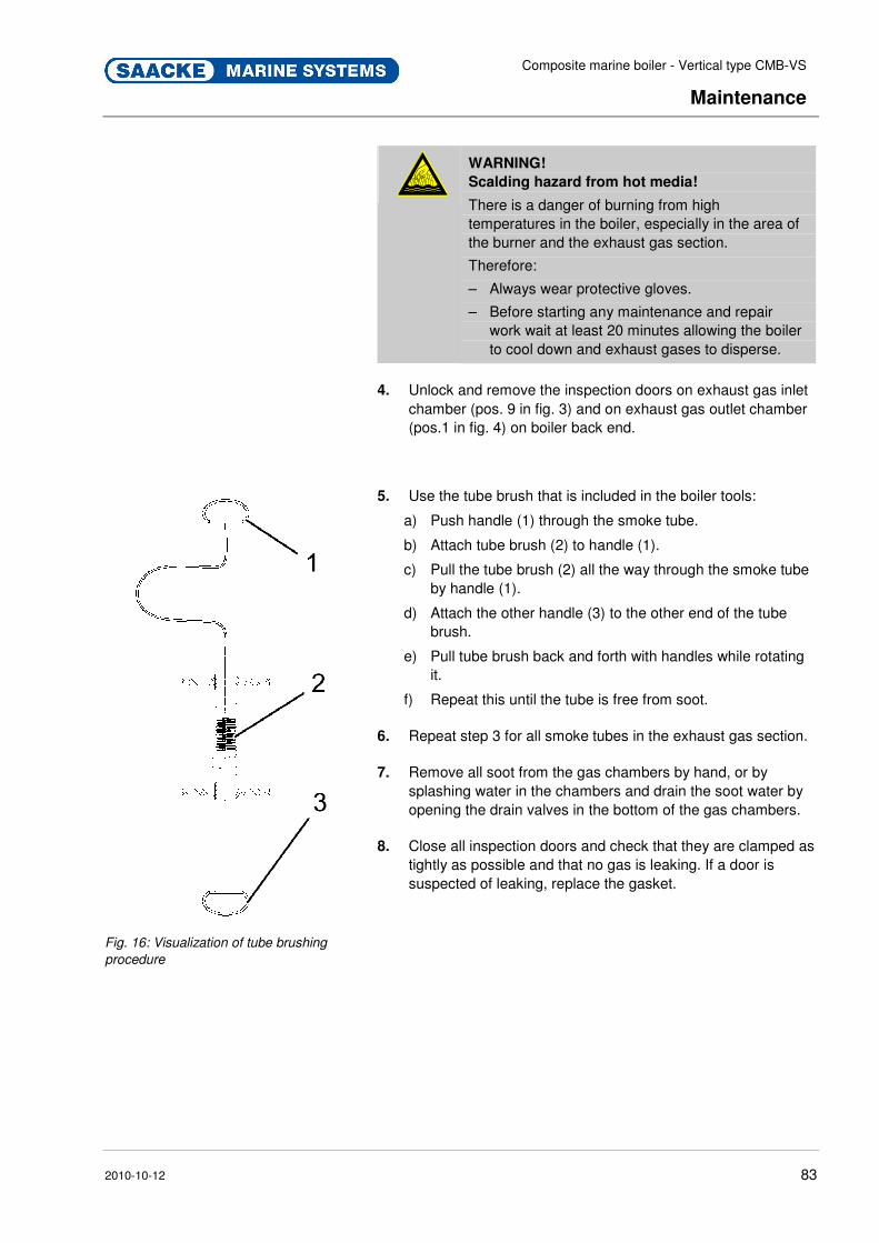
Composite marine boiler - Vertical type CMB-VS
Maintenance
2010-10-12 83
WARNING!
Scalding hazard from hot media!
There is a danger of burning from high temperatures in the boiler, especially in the area of the burner and the exhaust gas section.
Therefore:
– Always wear protective gloves.
– Before starting any maintenance and repair work wait at least 20 minutes allowing the boiler to cool down and exhaust gases to disperse.
4. Unlock and remove the inspection doors on exhaust gas inlet
chamber (pos. 9 in fig. 3) and on exhaust gas outlet chamber (pos.1 in fig. 4) on boiler back end.
Fig. 16: Visualization of tube brushing
procedure
5. Use the tube brush that is included in the boiler tools:
a) Push handle (1) through the smoke tube.
b) Attach tube brush (2) to handle (1).
c) Pull the tube brush (2) all the way through the smoke tube by handle (1).
d) Attach the other handle (3) to the other end of the tube brush.
e) Pull tube brush back and forth with handles while rotating it.
f) Repeat this until the tube is free from soot.
6. Repeat step 3 for all smoke tubes in the exhaust gas section.
7. Remove all soot from the gas chambers by hand, or by splashing water in the chambers and drain the soot water by opening the drain valves in the bottom of the gas chambers.
8. Close all inspection doors and check that they are clamped as tightly as possible and that no gas is leaking. If a door is suspected of leaking, replace the gasket.
Pos : 9.27 /KN 2006-SM /nL.. ... ... .. Sei tenumbr uch .. ... ... .. @ 8\mod_1141998334703_0.doc @ 75491
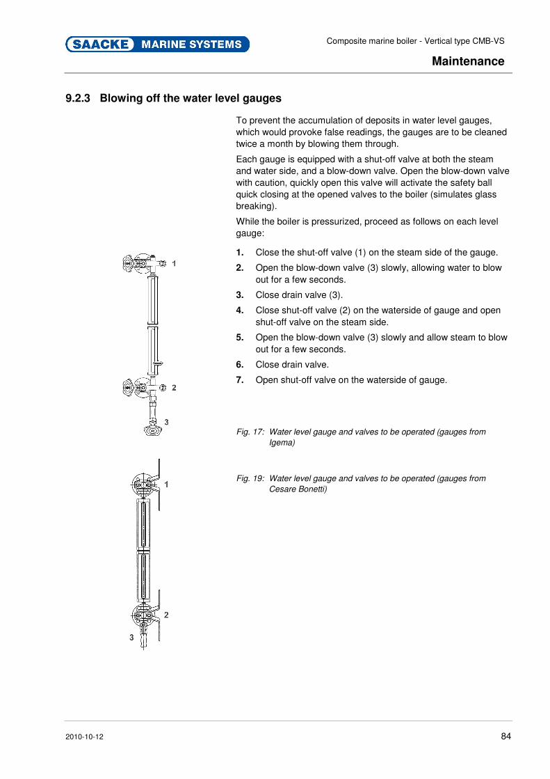
Composite marine boiler - Vertical type CMB-VS
Maintenance
2010-10-12 84
Pos : 9.28 /KN 2006-Pr ojekte/Saacke Mari ne Sys tems/Boiler/Wartung/1.1.1 Wasserstandsanzeiger entleeren (CM B-VS) @ 92\mod_1233053525447_2.doc @ 1391901
9.2.3 Blowing off the water level gauges
To prevent the accumulation of deposits in water level gauges, which would provoke false readings, the gauges are to be cleaned twice a month by blowing them through.
Each gauge is equipped with a shut-off valve at both the steam and water side, and a blow-down valve. Open the blow-down valve with caution, quickly open this valve will activate the safety ball quick closing at the opened valves to the boiler (simulates glass breaking).
While the boiler is pressurized, proceed as follows on each level gauge:
1. Close the shut-off valve (1) on the steam side of the gauge.
2. Open the blow-down valve (3) slowly, allowing water to blow out for a few seconds.
3. Close drain valve (3).
4. Close shut-off valve (2) on the waterside of gauge and open shut-off valve on the steam side.
5. Open the blow-down valve (3) slowly and allow steam to blow out for a few seconds.
6. Close drain valve.
7. Open shut-off valve on the waterside of gauge.
Fig. 17: Water level gauge and valves to be operated (gauges from
Igema)
Fig. 19: Water level gauge and valves to be operated (gauges from
Cesare Bonetti)
Pos : 9.29 /KN 2006-SM /nL.. ... ... .. Sei tenumbr uch .. ... ... .. @ 8\mod_1141998334703_0.doc @ 75491

Composite marine boiler - Vertical type CMB-VS
Maintenance
2010-10-12 85
Pos : 9.30 /KN 2006-SM /Allgemeines/150 1.1 Ersatzteile @ 8\mod_1142092320566_2.doc @ 75830
9.3 Spare parts
WARNING!
Safety hazard caused by wrong spare parts!
Wrong or faulty spare parts can adversely affect safety and cause damage, malfunctions or total failure.
Therefore:
– Use only genuine spare parts from the manufacturer.
Purchase spare parts from authorised dealers or directly from the manufacturer. For address, see page 2.
Pos: 9.31 /KN 2006-SM /Allgemeines/151 1.1.0 Di e Ersatzteilliste befi ndet sich im Anhang @ 8\mod_1142092788222_2.doc @ 75839
The spare-parts list can be found in the appendix. Pos: 9.32 /KN 2006-SM /nL.. ... ... .. Sei tenumbr uch .. ... ... .. @ 8\mod_1141998334703_0.doc @ 75491 Pos : 9.33 /KN 2006-SM /Wartung/009 1.1 M aßnahmen nach erfolgter Wartung_Titel @ 9\mod_1144438930025_2.doc @ 86930
9.4 Measures after maintenance Pos : 9.34 /KN 2006-SM /Wartung/009 1.1.0 M aßnahmen nach erfolgter Wartung --> Standard @ 9\mod_1144438981309_2.doc @ 86937
Perform the following steps after completing maintenance and before switching on the machine:
1. Check all previously loosened screw connections for a tight fit.
2. Check whether all previously removed protective devices and covers are properly installed again.
3. Make sure that all tools, materials and other equipment used were removed again from the work area.
4. Clean up work area and remove any substances left over, such as fluids, processing material or the like.
5. Make sure that all safety features on the machine are fully functional.
Pos : 9.35 /KN 2006-SM /nL.. ... ... .. Sei tenumbr uch .. ... ... .. @ 8\mod_1141998334703_0.doc @ 75491

Composite marine boiler - Vertical type CMB-VS
Maintenance
2010-10-12 86
Pos : 9.36 /KN 2006-Pr ojekte/Saacke Mari ne Sys tems/GCU /Wartung/1.1 Saacke Aftersales Ser vice @ 37\mod_1177406911644_2.doc @ 446889
9.5 SAACKE Aftersales Service
If you have a request or a special problem, you can communicate it to the SAACKE Aftersales Service at the telephone number:
+49 421 6495 5229
The SAACKE Aftersales Service can be reached at this number around the clock in the event of technical emergencies.
Procurement of Spare Parts All plant parts are listed in the Technical Documentation according to their TAG number. For ordering spare parts you determine the TAG number of the required part from the flow chart. You will find the corresponding SAACKE spare parts number of the part in the Technical Documentation.
There are different ways of ordering spare parts:
� by telephone at the number:
+49 421 6495 5229
� via the Internet:
http://www.saacke.de
Here it is possible to fill out a prepared form and send the order via the Internet.
NOTE!
Keep the plant number handy in any case. ===== Ende der Stückliste =====
Composite marine boiler - Vertical type CMB-VS
Index
2010-10-12 87
10 Index
A
Abbreviations........................................................ 7
Accident Prevention ........................................... 12
Action during malfunctions ................................. 68
Aftersales Service .............................................. 96
Assembly............................................................ 43
Auxiliary equipment ............................................ 27
B
Boiler Description ............................................... 24
C
Checks
Before Start-up ............................................... 55
Commissioning................................................... 49
Controls
Before Start-up ............................................... 55
Customer’s Responsibility.................................. 10
D
Depressurize, in which cases............................. 69
Depressurizing, fast way .................................... 70
Depressurizing, gently........................................ 71
Disposal.............................................................. 37
Draining off completely....................................... 72
Dry running......................................................... 62
During operation................................................. 56
E
Electric Current................................................... 15
F
Face protection................................................. 13
Fire
In case of ........................................................ 21
Prevention....................................................... 21
Fireproof protective clothing............................... 13
Functioning principle .......................................... 25
H
Hard hat ............................................................. 13
Heavy fireproof protective clothing................13
I
Inspection chart ..................................................83
Inspection of the boiler .......................................85
Inspection procedure ..........................................85
Installation of boiler mountings...........................47
Installation of exhaust gas connections .............47
Installation of instruments...................................47
Installing the boiler..............................................45
Intended Use ........................................................9
L
Liability..................................................................7
List of Abbreviations .............................................7
Long-term shut-down..........................................59
M
Maintenance .......................................................77
Maintenance chart ..............................................83
Malfunctions .......................................................64
N
Nitrogen ..............................................................17
Noise ..................................................................16
O
Operating personnel ...........................................19
Operation............................................................52
Operation Manual .................................................2
Overview.............................................................22
P
Packing.........................................................30, 37
Personal Safety Equipment................................13
Personnel ...........................................................19
commissioning ................................................64
installation .................................................39, 64
maintenance ...................................................77
Place of set-up....................................................41
Product Safety ....................................................11

Composite marine boiler - Vertical type CMB-VS
Index
2010-10-12 88
Protective Gear
for Installation ................................................. 40
for Transport .................................31, 54, 64, 77
Protective gloves ................................................ 13
Q
Qualified personnel ............................................ 19
R
Reference Documents ......................................... 7
S
Safety Measures
Accident Prevention........................................ 12
Organizational................................................. 10
Product Safety ................................................ 11
Safety Regulations ............................................. 12
Safety shoes....................................................... 13
Service Hotline ................................................... 96
Setting of safety valves ...................................... 50
Shut-down .......................................................... 58
Smoke tubes, temporary repair.......................... 75
Soot cleaning...................................................... 88
Soot deposits...................................................... 88
Spare parts ...................................................94, 96
Start-up
Prior to ............................................................55
Start-up routine...................................................55
Storage ...............................................................38
Storage ...............................................................30
Storage ...............................................................38
Structure .............................................................22
Symbols
in this manual....................................................6
Packing ...........................................................33
System control....................................................18
T
Transport ............................................................30
Transport inspection ...........................................32
Transport of the boiler ........................................34
Troubleshooting............................................64, 73
Tube brushing...................................................90
W
Water level gauges, Blowing off .........................93
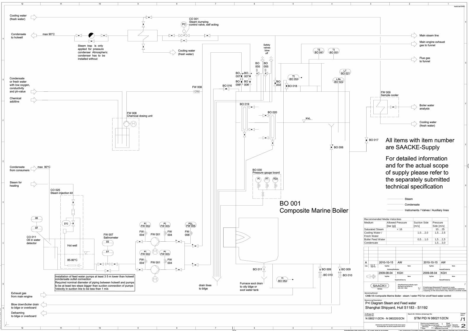
Recommended Media VelocitiesMedium Allowed Pressure
[bar (g)]Suction Side [m/s]
Pressure Side [m/s]
Saturated Steam < 16 10….25Cooling Water / Fresh Water
1,0….2,0 1,5….2,5
Boiler Feed Water 0,5….1,0 1,5….2,5Condensate 1,5….3,0
