components of hydraulic and pneumatic...
TRANSCRIPT
COMPONENTS OF HYDRAULIC AND PNEUMATIC SYSTEM
PRASHANT AMBADEKAR
ADVANTAGES OF PNEUMATIC SYSTEMS
High effectiveness
• Unlimited supply of air to produce compressed air.
• Not restricted by distance, as it can easily be
transported through pipes.
• Compressed air can be released directly into the
atmosphere without the need of processing.
High durability and reliability
• Pneumatic components are extremely durable and can
not be damaged easily.
Simple design
• Designs of pneumatic components are relatively simple.
• More suitable for use in automatic control systems.
PRASHANT AMBADEKAR P
NE
UM
AT
IC A
ND
HY
DR
AU
LIC
SY
ST
EM
High adaptability to harsh environment
• Comparatively compressed air is less affected by high
temperature, dust, corrosion, etc.
Safety
• Safer because they can work in inflammable environment
without causing fire or explosion.
• Pneumatic components do not burn or get overheated
when overloaded.
Easy selection of speed and pressure
• Speeds of rectilinear and oscillating movement of
pneumatic systems are easy to adjust.
• Pressure and volume of air can easily be adjusted.
ADVANTAGES OF PNEUMATIC SYSTEMS P
NE
UM
AT
IC A
ND
HY
DR
AU
LIC
SY
ST
EM
Environmental friendly
• The operation of pneumatic systems do not produce
pollutants.
• Pneumatic systems can work in environments that
demand high level of cleanliness.
Economical
• As pneumatic components are not expensive, the
costs of pneumatic systems are quite low.
• Pneumatic systems are very durable, the cost of
repair is significantly lower than that of other systems.
ADVANTAGES OF PNEUMATIC SYSTEMS P
NE
UM
AT
IC A
ND
HY
DR
AU
LIC
SY
ST
EM
Relatively low accuracy
• As the volume of air may change when compressed
or heated, the supply of air to the system may not be
accurate, causing a decrease in the overall accuracy
of the system.
Low loading
• As the cylinders are not very large, a pneumatic
system cannot drive loads that are too heavy.
Processing required before use
• Compressed air must be processed before use.
• Moving parts may wear out quickly due to friction.
LIMITATIONS OF PNEUMATIC SYSTEMS P
NE
UM
AT
IC A
ND
HY
DR
AU
LIC
SY
ST
EM
Uneven moving speed
• As air can easily be compressed, the moving speeds
of the pistons are relatively uneven.
Noise
• Noise will be produced when compressed air is
released from the pneumatic components.
LIMITATIONS OF PNEUMATIC SYSTEMS P
NE
UM
AT
IC A
ND
HY
DR
AU
LIC
SY
ST
EM
PN
EU
MA
TIC
AN
D H
YD
RA
UL
IC S
YS
TE
M
PN
EU
MA
TIC
AN
D H
YD
RA
UL
IC S
YS
TE
M
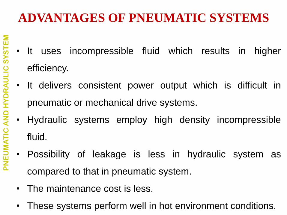
• It uses incompressible fluid which results in higher
efficiency.
• It delivers consistent power output which is difficult in
pneumatic or mechanical drive systems.
• Hydraulic systems employ high density incompressible
fluid.
• Possibility of leakage is less in hydraulic system as
compared to that in pneumatic system.
• The maintenance cost is less.
• These systems perform well in hot environment conditions.
ADVANTAGES OF PNEUMATIC SYSTEMS P
NE
UM
AT
IC A
ND
HY
DR
AU
LIC
SY
ST
EM
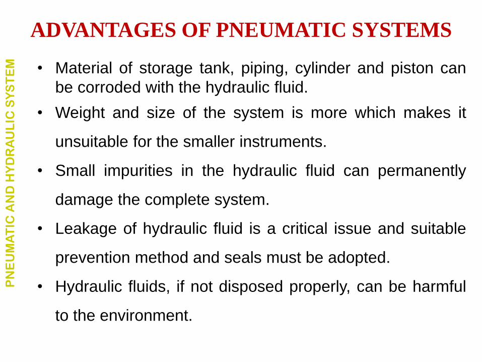
• Material of storage tank, piping, cylinder and piston can
be corroded with the hydraulic fluid.
• Weight and size of the system is more which makes it
unsuitable for the smaller instruments.
• Small impurities in the hydraulic fluid can permanently
damage the complete system.
• Leakage of hydraulic fluid is a critical issue and suitable
prevention method and seals must be adopted.
• Hydraulic fluids, if not disposed properly, can be harmful
to the environment.
ADVANTAGES OF PNEUMATIC SYSTEMS P
NE
UM
AT
IC A
ND
HY
DR
AU
LIC
SY
ST
EM
PN
EU
MA
TIC
AN
D H
YD
RA
UL
IC S
YS
TE
M
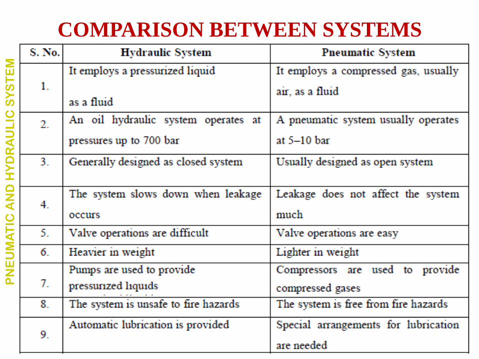
COMPARISON BETWEEN SYSTEMS
BASIC COMPONENTS OF A HYDRAULIC SYSTEM P
NE
UM
AT
IC A
ND
HY
DR
AU
LIC
SY
ST
EM
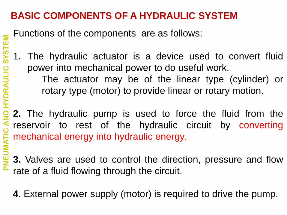
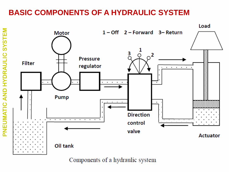
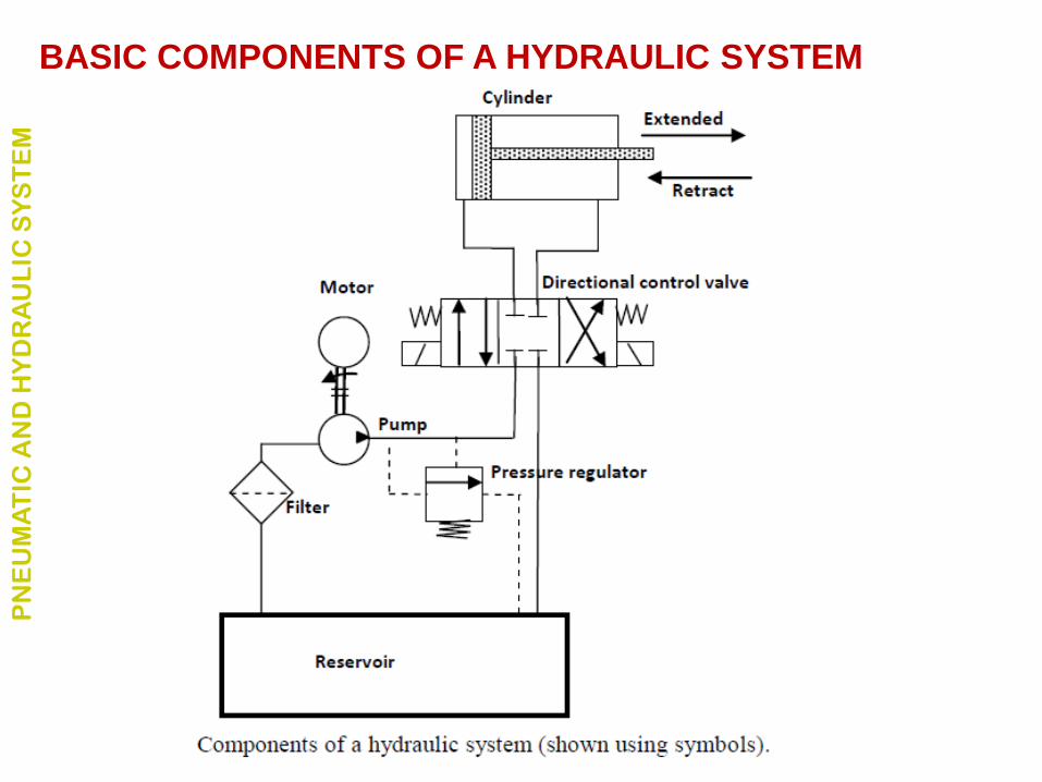
Functions of the components are as follows:
1. The hydraulic actuator is a device used to convert fluid
power into mechanical power to do useful work.
The actuator may be of the linear type (cylinder) or
rotary type (motor) to provide linear or rotary motion.
2. The hydraulic pump is used to force the fluid from the
reservoir to rest of the hydraulic circuit by converting
mechanical energy into hydraulic energy.
3. Valves are used to control the direction, pressure and flow
rate of a fluid flowing through the circuit.
4. External power supply (motor) is required to drive the pump.
BASIC COMPONENTS OF A HYDRAULIC SYSTEM P
NE
UM
AT
IC A
ND
HY
DR
AU
LIC
SY
ST
EM
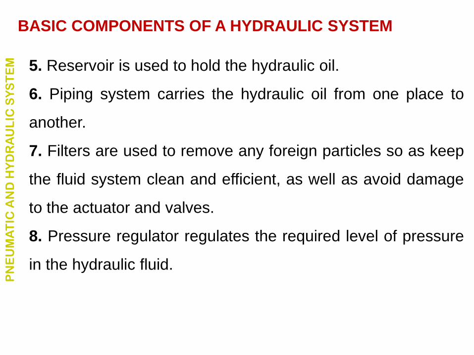
5. Reservoir is used to hold the hydraulic oil.
6. Piping system carries the hydraulic oil from one place to
another.
7. Filters are used to remove any foreign particles so as keep
the fluid system clean and efficient, as well as avoid damage
to the actuator and valves.
8. Pressure regulator regulates the required level of pressure
in the hydraulic fluid.
BASIC COMPONENTS OF A HYDRAULIC SYSTEM P
NE
UM
AT
IC A
ND
HY
DR
AU
LIC
SY
ST
EM
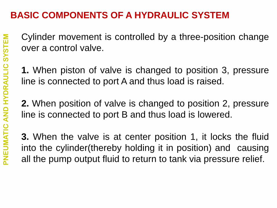
Cylinder movement is controlled by a three-position change
over a control valve.
1. When piston of valve is changed to position 3, pressure
line is connected to port A and thus load is raised.
2. When position of valve is changed to position 2, pressure
line is connected to port B and thus load is lowered.
3. When the valve is at center position 1, it locks the fluid
into the cylinder(thereby holding it in position) and causing
all the pump output fluid to return to tank via pressure relief.
BASIC COMPONENTS OF A HYDRAULIC SYSTEM P
NE
UM
AT
IC A
ND
HY
DR
AU
LIC
SY
ST
EM
BASIC COMPONENTS OF A HYDRAULIC SYSTEM P
NE
UM
AT
IC A
ND
HY
DR
AU
LIC
SY
ST
EM
Basic Components of Pneumatic System P
NE
UM
AT
IC A
ND
HY
DR
AU
LIC
SY
ST
EM
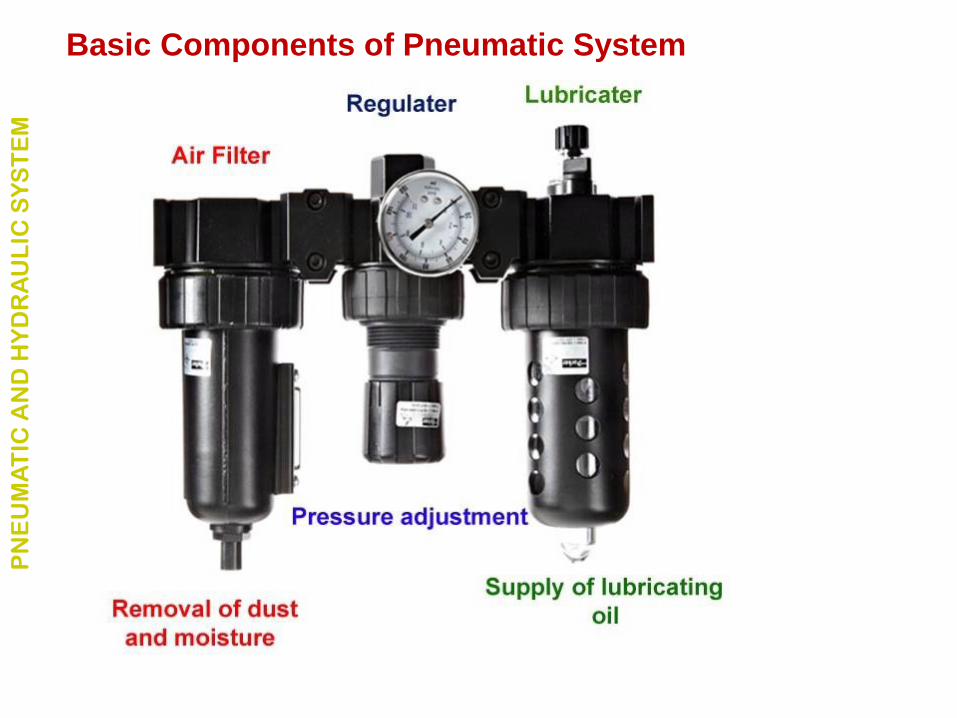
Air filters: These are used to filter out the contaminants from
the air.
Compressor: Compressed air is generated by using air
compressors.
Air cooler: During compression operation, air temperature
increases. Therefore coolers are used to reduce the
temperature of the compressed air.
Basic Components of Pneumatic System P
NE
UM
AT
IC A
ND
HY
DR
AU
LIC
SY
ST
EM
Control Valves: Control valves are used to regulate, control
and monitor for control of direction flow, pressure etc.
Air Actuator: Cylinders and motors are used to obtain the
required movements of mechanical elements of pneumatic
system.
Electric Motor: Transforms electrical energy into mechanical
energy. It is used to drive the compressor.
Receiver tank: The compressed air coming from the
compressor is stored in the air receiver.
Basic Components of Pneumatic System P
NE
UM
AT
IC A
ND
HY
DR
AU
LIC
SY
ST
EM
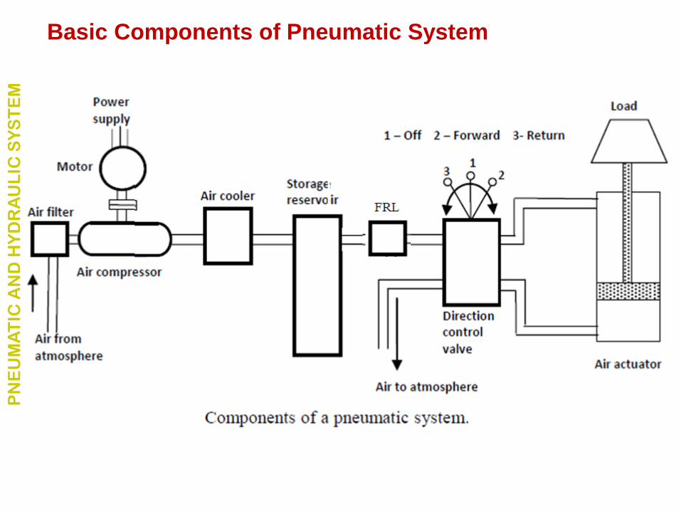
The functions of various components shown in Fig. are as
follows:
1. The pneumatic actuator converts the fluid power into
mechanical power to perform useful work.
2. The compressor is used to compress the fresh air drawn
from the atmosphere.
3. The storage reservoir is used to store a given volume of
compressed air.
4. The valves are used to control the direction, flow rate
and pressure of compressed air.
Basic Components of Pneumatic System P
NE
UM
AT
IC A
ND
HY
DR
AU
LIC
SY
ST
EM
5. External power supply (motor) is used to drive the
compressor.
6. The piping system carries the pressurized air from one
location to another.
Basic Components of Pneumatic System P
NE
UM
AT
IC A
ND
HY
DR
AU
LIC
SY
ST
EM
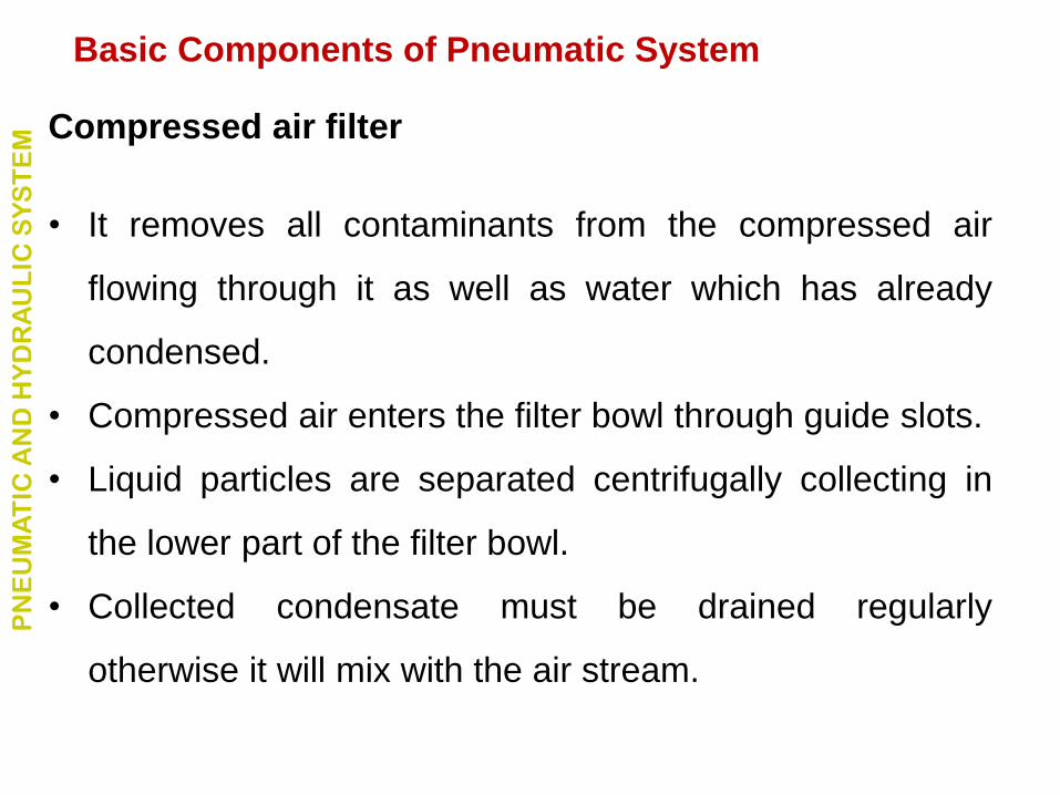
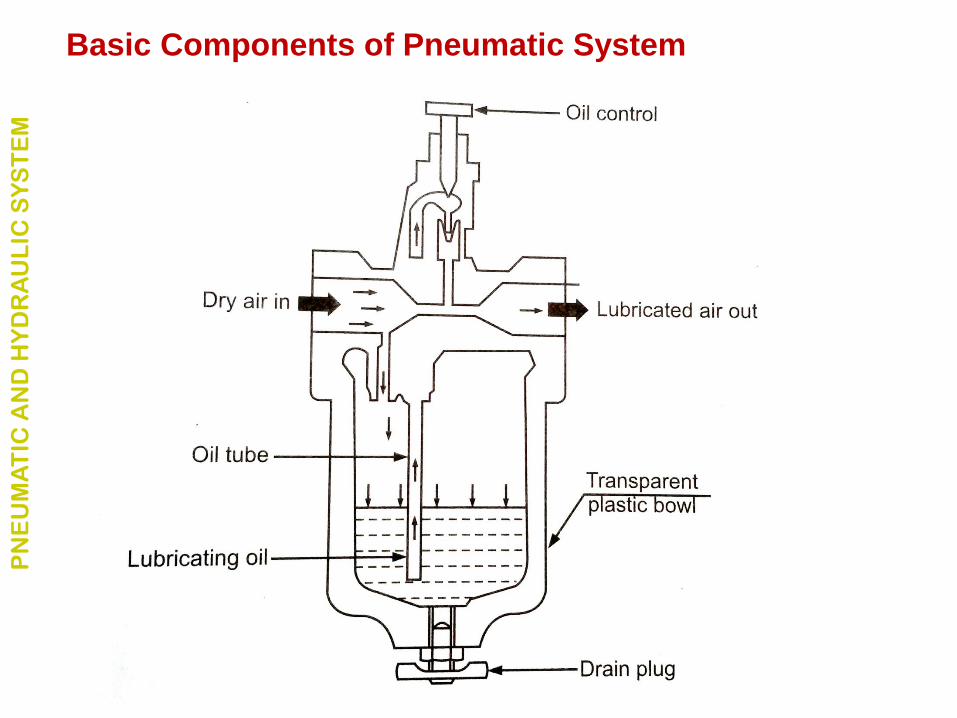
Compressed air filter
• It removes all contaminants from the compressed air
flowing through it as well as water which has already
condensed.
• Compressed air enters the filter bowl through guide slots.
• Liquid particles are separated centrifugally collecting in
the lower part of the filter bowl.
• Collected condensate must be drained regularly
otherwise it will mix with the air stream.
Basic Components of Pneumatic System P
NE
UM
AT
IC A
ND
HY
DR
AU
LIC
SY
ST
EM
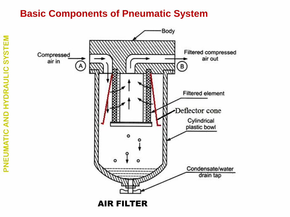
AIR FILTER
Basic Components of Pneumatic System P
NE
UM
AT
IC A
ND
HY
DR
AU
LIC
SY
ST
EM
Compressed air regulator
• The purpose of the regulator is to keep the operating
pressure of the system virtually constant regardless of
fluctuations in the line pressure and the air consumption.
• High pressure of incoming air is to be reduced.
Basic Components of Pneumatic System P
NE
UM
AT
IC A
ND
HY
DR
AU
LIC
SY
ST
EM
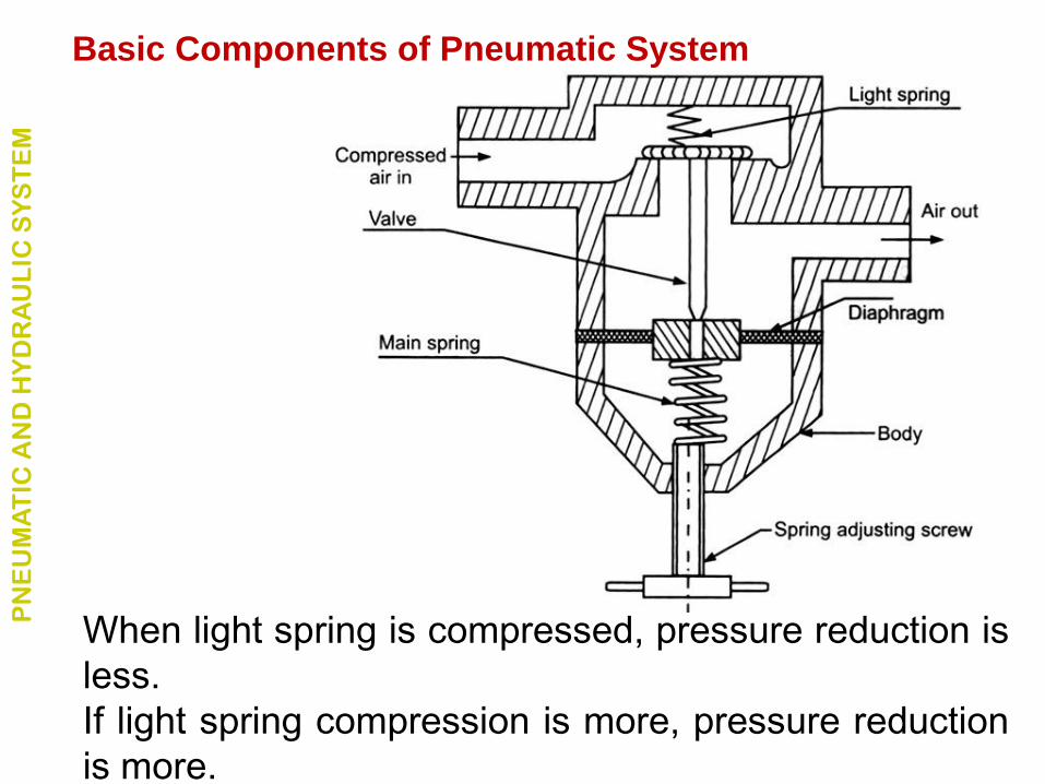
When light spring is compressed, pressure reduction is
less.
If light spring compression is more, pressure reduction
is more.
Basic Components of Pneumatic System P
NE
UM
AT
IC A
ND
HY
DR
AU
LIC
SY
ST
EM
Compressed air lubricator
• The purpose of the lubricator is to deliver a metered
quantity of oil mist into the air distribution system when
necessary for the operation of the pneumatic system.
Basic Components of Pneumatic System P
NE
UM
AT
IC A
ND
HY
DR
AU
LIC
SY
ST
EM
Basic Components of Pneumatic System P
NE
UM
AT
IC A
ND
HY
DR
AU
LIC
SY
ST
EM
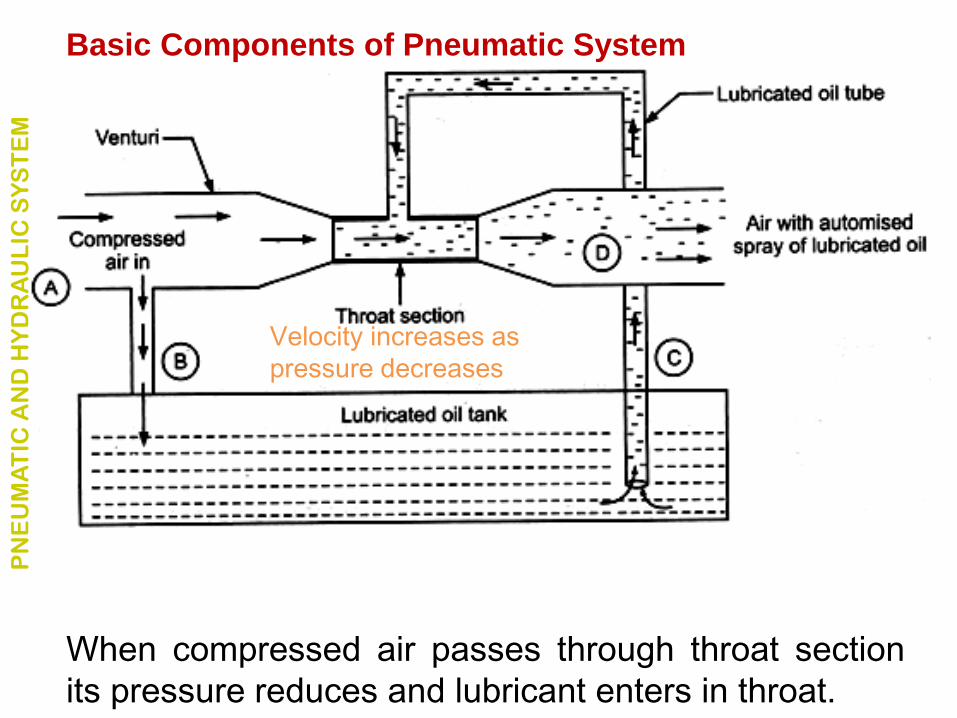
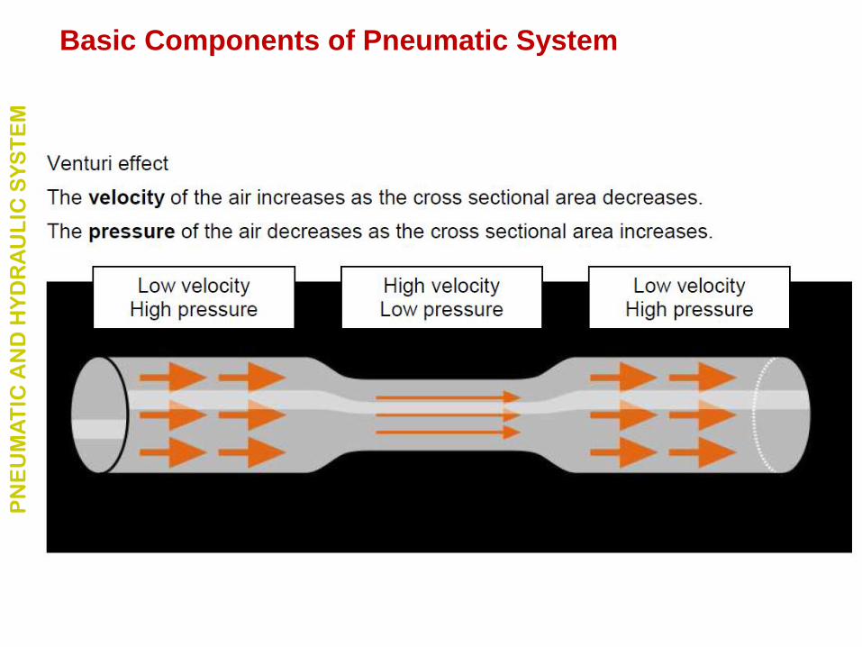
When compressed air passes through throat section
its pressure reduces and lubricant enters in throat.
Velocity increases as
pressure decreases
Basic Components of Pneumatic System P
NE
UM
AT
IC A
ND
HY
DR
AU
LIC
SY
ST
EM
Basic Components of Pneumatic System P
NE
UM
AT
IC A
ND
HY
DR
AU
LIC
SY
ST
EM
PN
EU
MA
TIC
AN
D H
YD
RA
UL
IC S
YS
TE
M
Basic Components of Pneumatic System
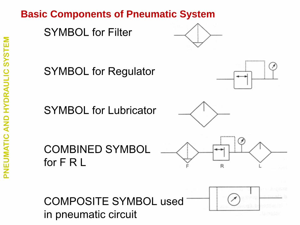
SYMBOL for Filter
SYMBOL for Regulator
SYMBOL for Lubricator
COMBINED SYMBOL
for F R L
COMPOSITE SYMBOL used
in pneumatic circuit
PN
EU
MA
TIC
AN
D H
YD
RA
UL
IC S
YS
TE
M
Basic Components of Pneumatic System
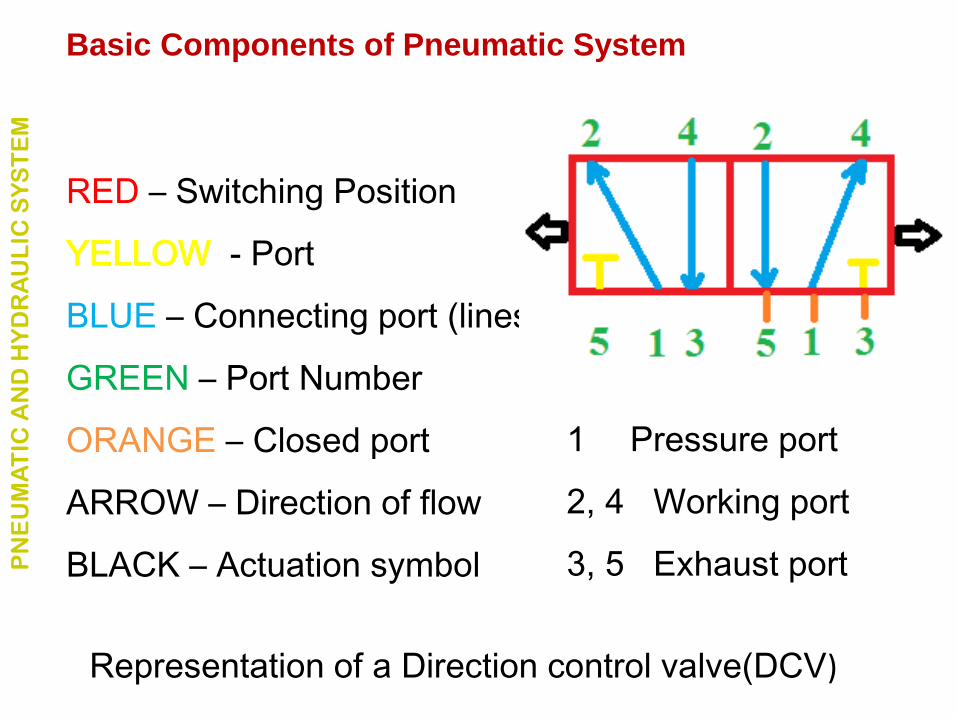
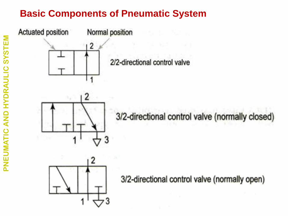
Representation of a Direction control valve(DCV)
RED – Switching Position
YELLOW - Port
BLUE – Connecting port (lines)
GREEN – Port Number
ORANGE – Closed port
ARROW – Direction of flow
BLACK – Actuation symbol
1 Pressure port
2, 4 Working port
3, 5 Exhaust port PN
EU
MA
TIC
AN
D H
YD
RA
UL
IC S
YS
TE
M
Basic Components of Pneumatic System
PN
EU
MA
TIC
AN
D H
YD
RA
UL
IC S
YS
TE
M
Basic Components of Pneumatic System
PN
EU
MA
TIC
AN
D H
YD
RA
UL
IC S
YS
TE
M
Basic Components of Pneumatic System
PN
EU
MA
TIC
AN
D H
YD
RA
UL
IC S
YS
TE
M
Basic Components of Pneumatic System
PN
EU
MA
TIC
AN
D H
YD
RA
UL
IC S
YS
TE
M
Basic Components of Pneumatic System
Three types of valves are employed in hydraulic systems:
1. Directional control valves
2. Flow control valves
3. Pressure control valves
PN
EU
MA
TIC
AN
D H
YD
RA
UL
IC S
YS
TE
M
Basic Components of Pneumatic System
• Control the distribution of energy in a fluid power system.
• Provide the direction to the fluid.
• Control the start, stop and change in direction of the fluid flow.
• Contain ports that are external openings for the fluid.
• Number of ports is usually identified by the term ‘way’.
• For example, a valve with four ports is named as four-way valve.
• The fluid flow rate is responsible for the speed of actuator.
PN
EU
MA
TIC
AN
D H
YD
RA
UL
IC S
YS
TE
M
Direction control valve
DCV can be classified in the following manner:
1. Type of construction:
• Poppet valves
• Spool valves
2. Number of ports:
• Two- way valves
• Three – way valves
• Four- way valves.
PN
EU
MA
TIC
AN
D H
YD
RA
UL
IC S
YS
TE
M
Direction control valve
DCV can be classified in the following manner:
3. Number of switching position:
• Two – position
• Three - position
4. Actuating mechanism:
• Manual actuation
• Mechanical actuation
• Solenoid actuation
• Hydraulic actuation
• Pneumatic actuation • Indirect actuation
PN
EU
MA
TIC
AN
D H
YD
RA
UL
IC S
YS
TE
M
Direction control valve
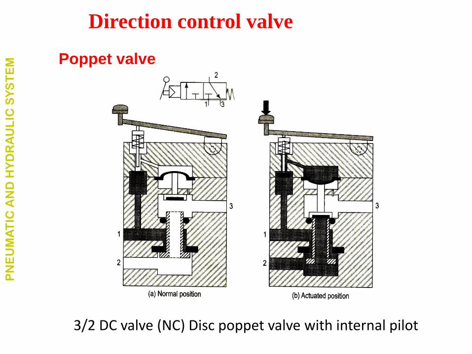
3/2 DC valve (NC) Disc poppet valve with internal pilot
PN
EU
MA
TIC
AN
D H
YD
RA
UL
IC S
YS
TE
M
Direction control valve
Poppet valve
PN
EU
MA
TIC
AN
D H
YD
RA
UL
IC S
YS
TE
M
Direction control valve
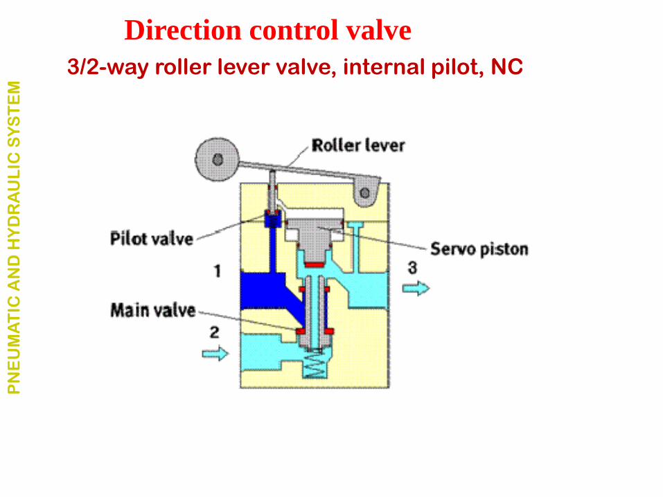
3/2-way roller lever valve, internal pilot, NC
• A small hole connects the pressure connection (1) and the
pilot valve.
• If the roller lever is operated, the pilot valve opens.
• Compressed air flows to the servo piston and actuates the
main valve disc.
• First the connection from port (2) to port (3) is closed.
• Second the disc seat of the main valve opens, allowing the
air to flow from pressure supply port (1) to working port (2).
The air supply for the pilot valve is either internally
connected to the supply port (1) or supplied through a
separate port (mostly numbered 12 or 14).
PN
EU
MA
TIC
AN
D H
YD
RA
UL
IC S
YS
TE
M
Direction control valve
3/2-way roller lever valve, internal pilot, NC
Spool valve
• Name is derived from their appearance.
• It consists of a shaft sliding in a bore.
• The spool is sealed along the clearance between moving
spool and housing (valve body).
• The amount of leakage depends on:
• the amount of clearance
• viscosity of fluid
• the level of the pressure.
• The grooves guide the fluid flow by interconnecting or
blocking the holes (ports).
PN
EU
MA
TIC
AN
D H
YD
RA
UL
IC S
YS
TE
M
Direction control valve
Spool valve
• The spool valves are categorized according to:
• number of operating positions
• the way hydraulic lines interconnections.
• The standard terms are referred as
• Port ‘P’ is pressure port,
• Port ‘T’ is tank port
• Port ‘A’ and Port ‘B’ as working ports.
• The actuators can move in forward or backward direction
depending on the connectivity of the pressure and tank port
with the actuators port.
PN
EU
MA
TIC
AN
D H
YD
RA
UL
IC S
YS
TE
M
Direction control valve
PN
EU
MA
TIC
AN
D H
YD
RA
UL
IC S
YS
TE
M
Direction control valve
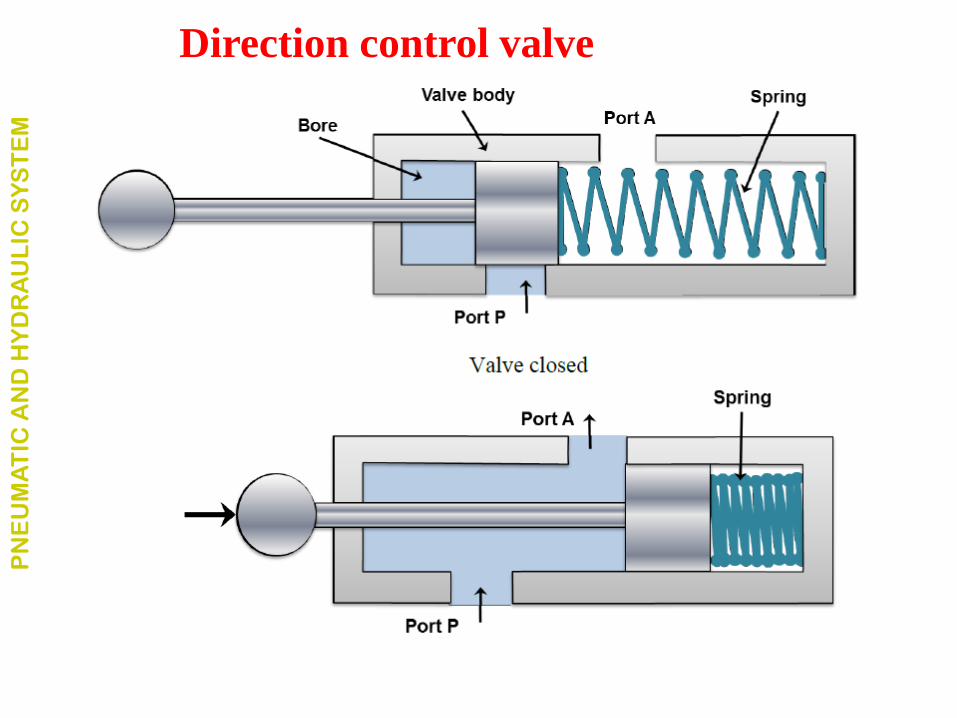
2 Number of ports Two way valves
• Have only two ports
• Also known as on-off valves because they allow the fluid flow only
in direction.
• Normally, the valve is closed.
• Available as normally open and normally closed function. PN
EU
MA
TIC
AN
D H
YD
RA
UL
IC S
YS
TE
M
Direction control valve
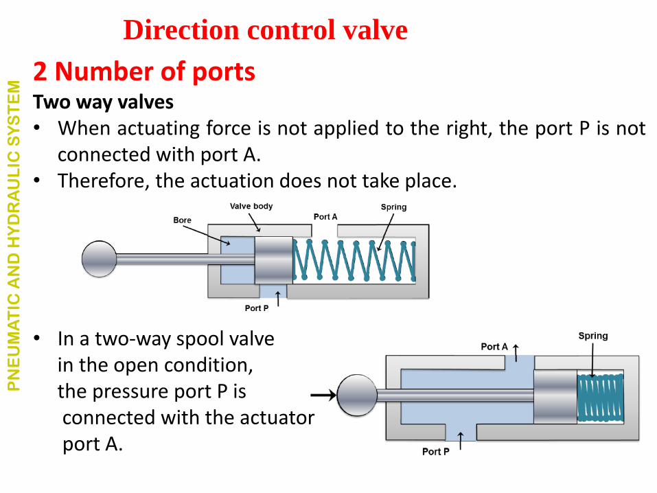
2 Number of ports Two way valves • When actuating force is not applied to the right, the port P is not
connected with port A. • Therefore, the actuation does not take place.
• In a two-way spool valve in the open condition, the pressure port P is connected with the actuator port A.
PN
EU
MA
TIC
AN
D H
YD
RA
UL
IC S
YS
TE
M
Direction control valve
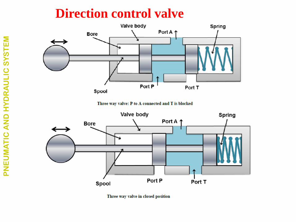
2 Number of ports Three way valves
• When a valve has one pressure port, one tank port and one
working port
• In this valve, the pressure port pressurizes one port and exhausts
another one.
• Only one actuator port is opened at a time.
• In some cases a neutral position is also available when both the
ports are blocked.
• Generally, these valves are used to operate single acting cylinders.
PN
EU
MA
TIC
AN
D H
YD
RA
UL
IC S
YS
TE
M
Direction control valve
PN
EU
MA
TIC
AN
D H
YD
RA
UL
IC S
YS
TE
M
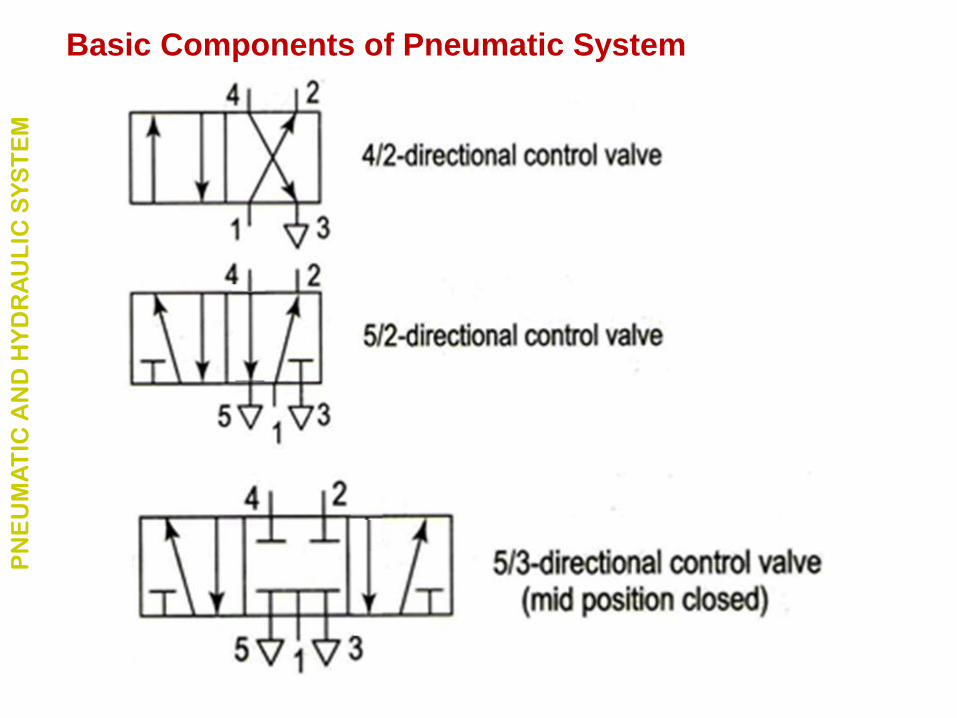
Direction control valve
Four way valves
• It is generally used to operate the cylinders and fluid motors
in both the directions.
• The four ways are: pump port P, tank port T, and two
working ports A and B connected to the actuator.
• The primary function of a four way valve is to pressurize
and exhaust two working ports A and B alternatively.
PN
EU
MA
TIC
AN
D H
YD
RA
UL
IC S
YS
TE
M
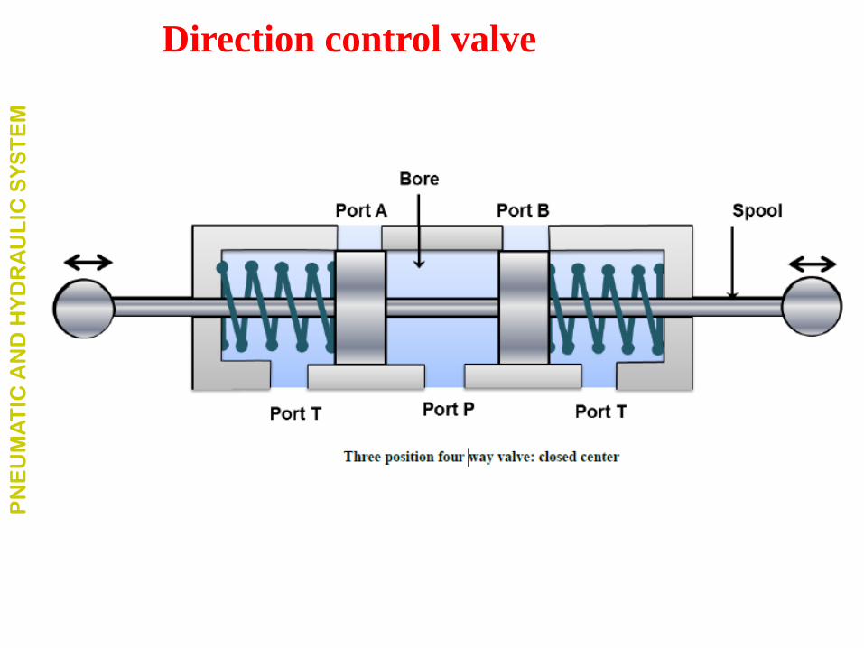
Direction control valve
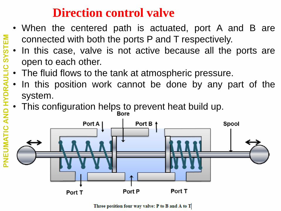
• When the centered path is actuated, port A and B are
connected with both the ports P and T respectively.
• In this case, valve is not active because all the ports are
open to each other.
• The fluid flows to the tank at atmospheric pressure.
• In this position work cannot be done by any part of the
system. • This configuration helps to prevent heat build up.
PN
EU
MA
TIC
AN
D H
YD
RA
UL
IC S
YS
TE
M
Direction control valve
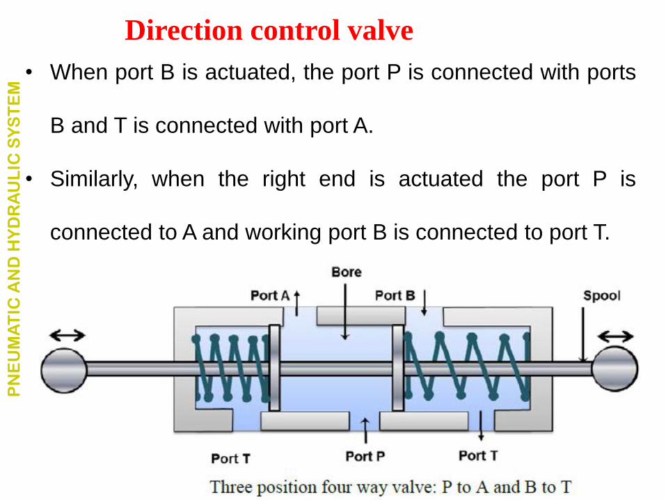
• When port B is actuated, the port P is connected with ports
B and T is connected with port A.
• Similarly, when the right end is actuated the port P is
connected to A and working port B is connected to port T.
PN
EU
MA
TIC
AN
D H
YD
RA
UL
IC S
YS
TE
M
Direction control valve
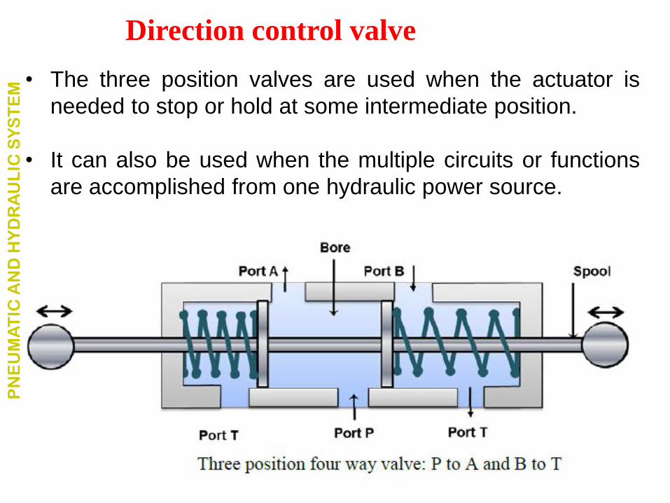
• The three position valves are used when the actuator is
needed to stop or hold at some intermediate position.
• It can also be used when the multiple circuits or functions
are accomplished from one hydraulic power source.
PN
EU
MA
TIC
AN
D H
YD
RA
UL
IC S
YS
TE
M
Direction control valve
According to number/ways of switching position
Three position valves
• Are used in double-acting cylinders
• Perform advance, hold and return operation to the piston.
• Have three switching positions.
• They have a variety of possible flow path configurations
but have identical flow path configuration. PN
EU
MA
TIC
AN
D H
YD
RA
UL
IC S
YS
TE
M
Direction control valve
PN
EU
MA
TIC
AN
D H
YD
RA
UL
IC S
YS
TE
M
Direction control valve
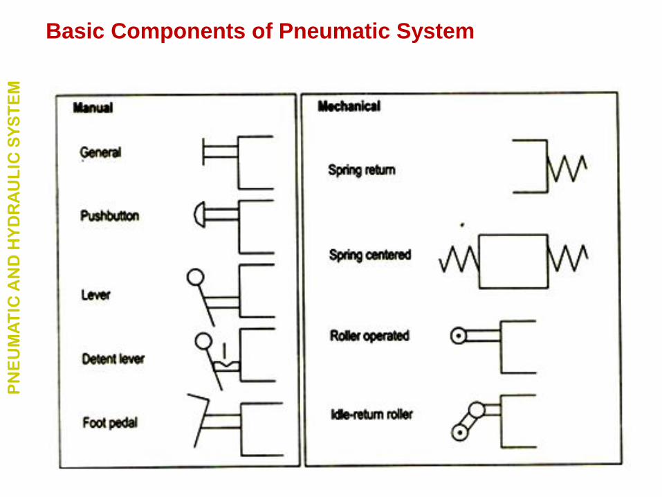
2. Classification based on actuation mechanism
2.1 Manual actuation
• In this type, the spool is operated manually.
• Manual actuators are hand lever, push button and pedals
etc.
PN
EU
MA
TIC
AN
D H
YD
RA
UL
IC S
YS
TE
M
Direction control valve
2.2 Mechanical actuation
• The DCV spool can be operated by using mechanical
elements.
• Roller and cam, roller and plunger and rack and pinion etc.
• Here the spool end is of roller or a pinion gear type.
• The plunger or cam or rack gear is attached to the actuator.
• Thus, the mechanical elements gain some motion relative
to the actuator (cylinder piston) which can be used for the
actuation.
PN
EU
MA
TIC
AN
D H
YD
RA
UL
IC S
YS
TE
M
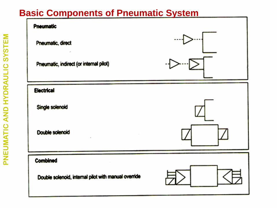
Direction control valve
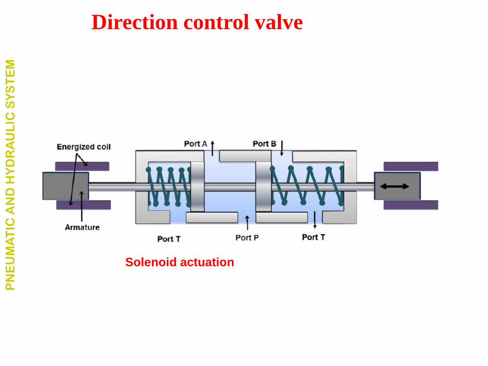
2.3 Solenoid actuation
• The solenoid actuation is also known as electrical actuation.
• The energized solenoid coil creates a magnetic force which
pulls the armature into the coil.
• This movement of armature controls the spool position.
• The main advantage of solenoid actuation is its less
switching time.
PN
EU
MA
TIC
AN
D H
YD
RA
UL
IC S
YS
TE
M
Direction control valve
PN
EU
MA
TIC
AN
D H
YD
RA
UL
IC S
YS
TE
M
Direction control valve
Solenoid actuation
2.4 Hydraulic actuation
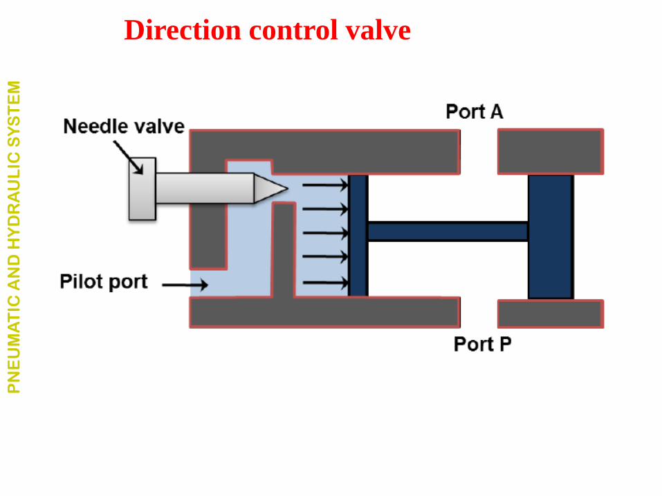
• This type actuation is usually known as pilot-actuated valve.
• The hydraulic pressure is directly applied on the spool.
• The pilot port is located on one end of the valve.
• Fluid entering from pilot port operates against the piston
and forces the spool to move forward.
• The needle valve is used to control the speed of the
actuation.
PN
EU
MA
TIC
AN
D H
YD
RA
UL
IC S
YS
TE
M
Direction control valve
PN
EU
MA
TIC
AN
D H
YD
RA
UL
IC S
YS
TE
M
Direction control valve
2.5 Pneumatic actuation
• DCV can also be operated by applying compressed air
against a piston at either end of the valve spool.
• The construction of the system is similar to the hydraulic
actuation.
• The only difference would be the actuation medium.
• The actuation medium is the compressed air in pneumatic
actuation system.
PN
EU
MA
TIC
AN
D H
YD
RA
UL
IC S
YS
TE
M
Direction control valve
2.6 Indirect actuation of directional control valve
• The direction control valve can be operated by manual,
mechanical, solenoidal (electrical), hydraulic (pilot) and
pneumatic actuations.
• The mode of actuation does not have any influence on the
basic operation of the hydraulic circuits.
• Mostly, the direct actuation is restricted to use with smaller
valves only because usually lot of force is not available.
• The availability of limited force is the greatest disadvantage
of the direct actuation systems.
PN
EU
MA
TIC
AN
D H
YD
RA
UL
IC S
YS
TE
M
Direction control valve
2.6 Indirect actuation of directional control valve
• In practice, the force required to shift the spool is quiet
higher.
• Therefore, the larger valves are often indirectly actuated in
sequence.
• First, the smaller valve is actuated directly and the flow from
the smaller valve is directed to either side of the larger
valve.
• The control fluid can be supplied by the same circuit or by a
separate circuit.
• The pilot valve pressure is usually supplied internally.
• These two valves are often incorporated as a single unit.
PN
EU
MA
TIC
AN
D H
YD
RA
UL
IC S
YS
TE
M
Direction control valve
• Speed of actuator needs to be controlled for desired o/p.
• Actuator speed can be controlled by regulating fluid flow.
• FCV can regulate flow or pressure of fluid.
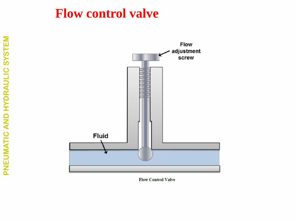
• Fluid flow is controlled by varying area of the valve
opening through which fluid passes.
• Fluid flow can be decreased by reducing the area of the
valve opening and it can be increased by increasing the
area of the valve opening.
• Example to the fluid flow control valve is the tap.
• The pressure adjustment screw varies the fluid flow area
in the pipe to control the discharge rate.
PN
EU
MA
TIC
AN
D H
YD
RA
UL
IC S
YS
TE
M
Flow control valve
PN
EU
MA
TIC
AN
D H
YD
RA
UL
IC S
YS
TE
M
Flow control valve
Types Flow Control Valves
• The flow control valves work on applying a variable
restriction in the flow path.
• Based on the construction; there are mainly four types
Plug valve
Butterfly valve
Ball valve
PN
EU
MA
TIC
AN
D H
YD
RA
UL
IC S
YS
TE
M
Flow control valve
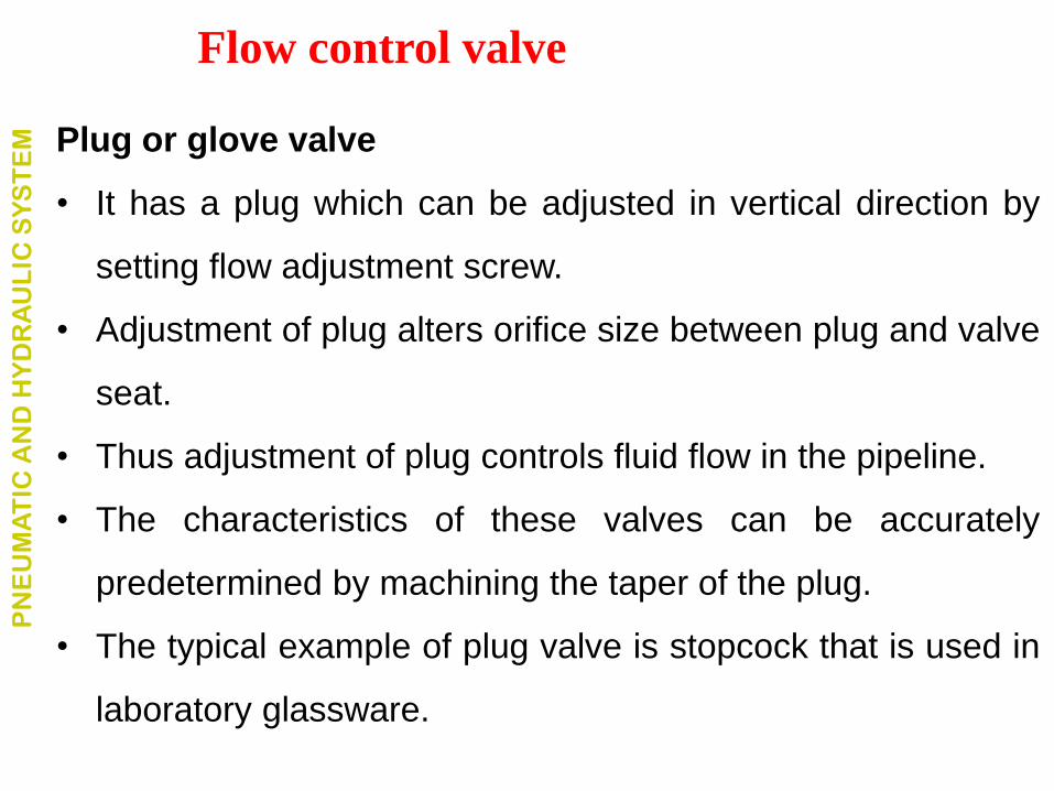
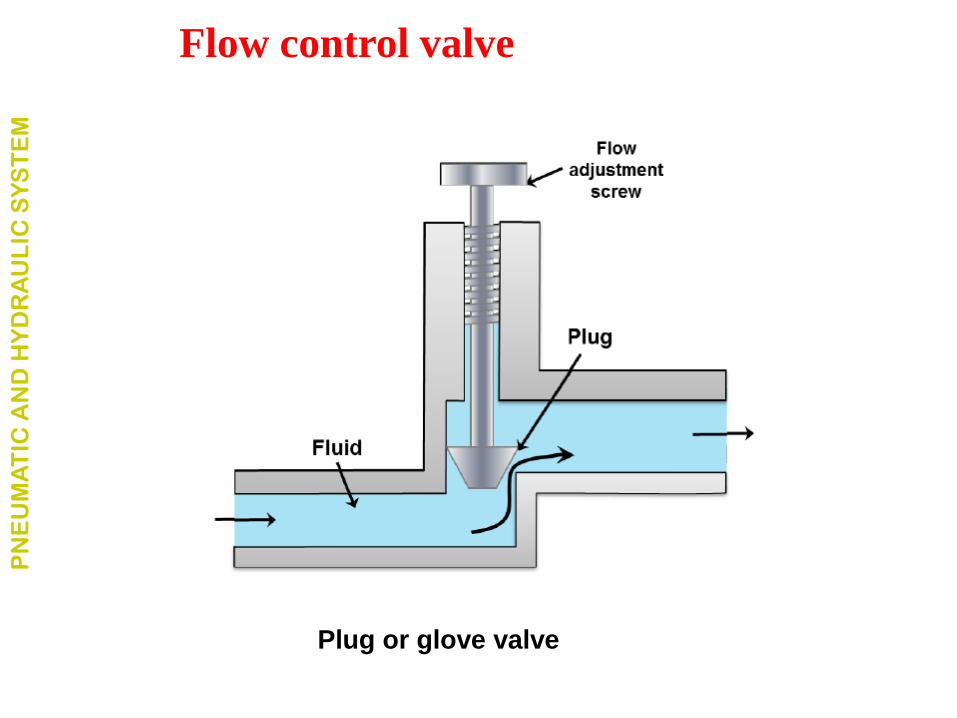
Plug or glove valve
• It has a plug which can be adjusted in vertical direction by
setting flow adjustment screw.
• Adjustment of plug alters orifice size between plug and valve
seat.
• Thus adjustment of plug controls fluid flow in the pipeline.
• The characteristics of these valves can be accurately
predetermined by machining the taper of the plug.
• The typical example of plug valve is stopcock that is used in
laboratory glassware.
PN
EU
MA
TIC
AN
D H
YD
RA
UL
IC S
YS
TE
M
Flow control valve
PN
EU
MA
TIC
AN
D H
YD
RA
UL
IC S
YS
TE
M
Flow control valve
Plug or glove valve
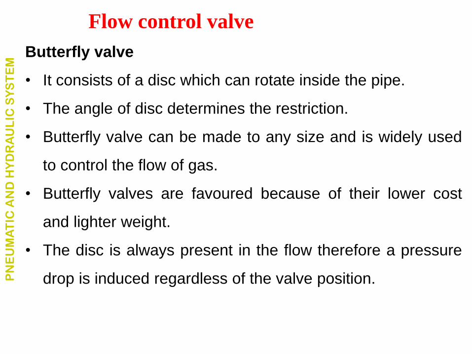
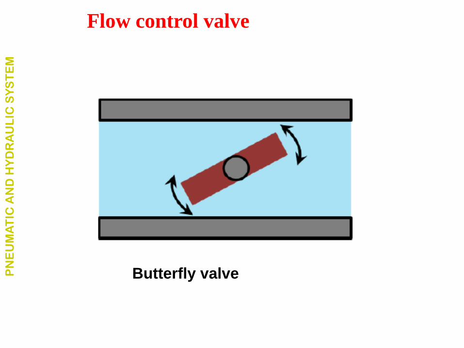
Butterfly valve
• It consists of a disc which can rotate inside the pipe.
• The angle of disc determines the restriction.
• Butterfly valve can be made to any size and is widely used
to control the flow of gas.
• Butterfly valves are favoured because of their lower cost
and lighter weight.
• The disc is always present in the flow therefore a pressure
drop is induced regardless of the valve position. PN
EU
MA
TIC
AN
D H
YD
RA
UL
IC S
YS
TE
M
Flow control valve
PN
EU
MA
TIC
AN
D H
YD
RA
UL
IC S
YS
TE
M
Flow control valve
Butterfly valve
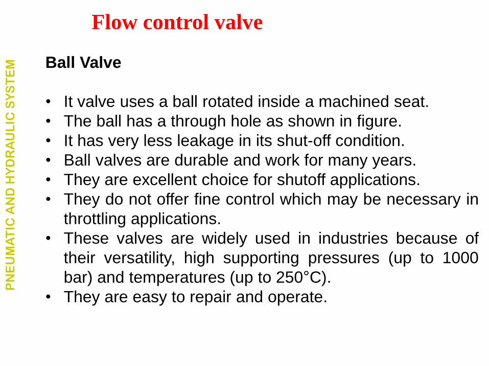
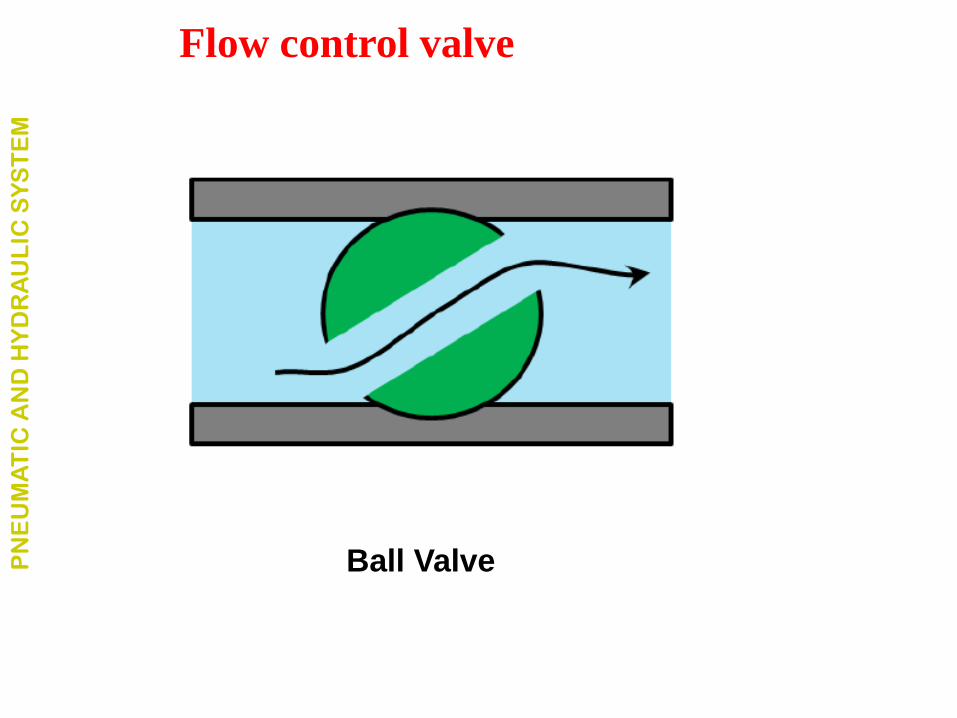
Ball Valve
• It valve uses a ball rotated inside a machined seat.
• The ball has a through hole as shown in figure.
• It has very less leakage in its shut-off condition.
• Ball valves are durable and work for many years.
• They are excellent choice for shutoff applications.
• They do not offer fine control which may be necessary in
throttling applications.
• These valves are widely used in industries because of
their versatility, high supporting pressures (up to 1000
bar) and temperatures (up to 250°C).
• They are easy to repair and operate.
PN
EU
MA
TIC
AN
D H
YD
RA
UL
IC S
YS
TE
M
Flow control valve
PN
EU
MA
TIC
AN
D H
YD
RA
UL
IC S
YS
TE
M
Flow control valve
Ball Valve
• They are used to protect the hydraulic components from
excessive pressure.
• This is required for safe operation of the system.
• Its primary function is to limit the system pressure within a
specified range.
• It is normally a closed type
• Valve opens when the pressure exceeds a specified
maximum value by diverting pump flow back to the tank.
• Simplest valve contains a poppet held in a seat against the
spring force.
PN
EU
MA
TIC
AN
D H
YD
RA
UL
IC S
YS
TE
M
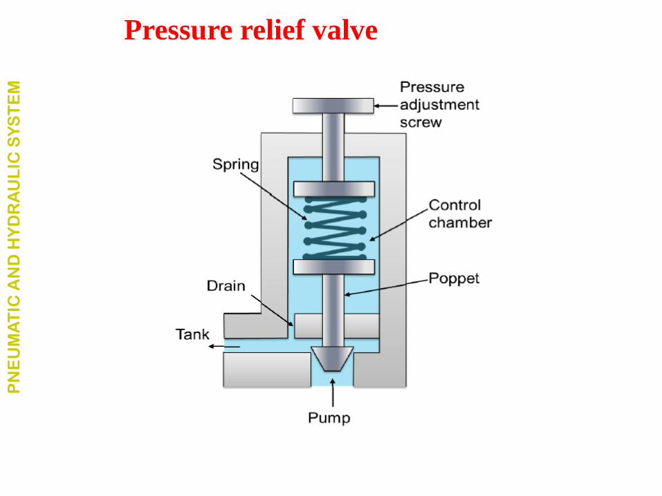
Pressure relief valve
• The fluid enters from the opposite side of the poppet.
• When the system pressure exceeds the preset value, the
poppet lifts and the fluid is escaped through the orifice to
the storage tank directly.
• It reduces the system pressure and as the pressure
reduces to the set limit again the valve closes.
• This valve does not provide a flat cut-off pressure limit with
flow rate because the spring must be deflected more when
the flow rate is higher. PN
EU
MA
TIC
AN
D H
YD
RA
UL
IC S
YS
TE
M
Pressure relief valve
PN
EU
MA
TIC
AN
D H
YD
RA
UL
IC S
YS
TE
M
Pressure relief valve
Compressor:
• It is a mechanical device which converts mechanical
energy into fluid energy.
• The compressor increases the air pressure by reducing
its volume which also increases the temperature of the
compressed air.
• The compressor is selected based on the pressure it
needs to operate and the delivery volume.
PN
EU
MA
TIC
AN
D H
YD
RA
UL
IC S
YS
TE
M
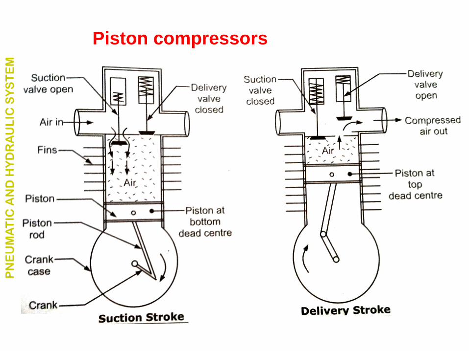
Piston compressors
• The simplest form is single cylinder compressor.
• It produces one pulse of air per piston stroke.
• As the piston moves down during the inlet stroke the inlet
valve opens and air is drawn into the cylinder.
• As the piston moves up the inlet valve closes and the
exhaust valve opens which allows the air to be expelled.
PN
EU
MA
TIC
AN
D H
YD
RA
UL
IC S
YS
TE
M
PN
EU
MA
TIC
AN
D H
YD
RA
UL
IC S
YS
TE
M
Piston compressors
Pneumatic components are designed for a maximum
operating pressure of 8 - 10 bar.
In practice it operate between 5 and 6 bar for economic use.
Due to the pressure losses in the distribution system the
compressor should deliver between 6.5 and 7 bar to attain
these figures.
PN
EU
MA
TIC
AN
D H
YD
RA
UL
IC S
YS
TE
M
• The selection of pipe diameter of the air distribution system is
governed by:
• Flow rate • Line length • Permissible pressure loss • Operating pressure • Number of flow control points in the line
PN
EU
MA
TIC
AN
D H
YD
RA
UL
IC S
YS
TE
M
Selection of pipe diameter in Pneumatics
Mainly used for precise control of larger forces.
Industrial:
Plastic processing machineries, steel making and primary
metal extraction applications, automated production lines,
machine tool industries, paper industries, textile machineries,
R & D equipment and robotic systems etc.
Mobile hydraulics:
Tractors, irrigation system, earthmoving equipment, material
handling equipment, commercial vehicles, tunnel boring
equipment, rail equipment, building and construction
machineries and drilling rigs etc.
PN
EU
MA
TIC
AN
D H
YD
RA
UL
IC S
YS
TE
M
APPLICATIONS OF HYDRAULIC SYSTEMS
Automobiles:
It is used in the systems like breaks, shock absorbers, steering
system, wind shield, lift and cleaning etc.
Marine applications:
It mostly covers ocean going vessels, fishing boats and navel
equipment.
Aerospace equipment:
There are equipment and systems used for raddar control,
flight control and transmission etc. which are used in airplanes,
rockets and spaceships.
PN
EU
MA
TIC
AN
D H
YD
RA
UL
IC S
YS
TE
M
APPLICATIONS OF HYDRAULIC SYSTEMS