components for hydraulic equipment general actions …edisp/... · components for hydraulic...
TRANSCRIPT
13:50-06 Issue 5 en-G
Components for hydraulic equipment
General356 9
72
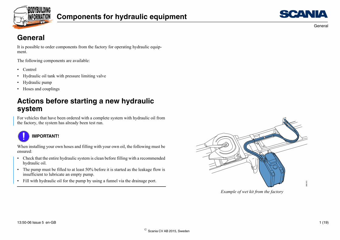
Example of wet kit from the factory
GeneralIt is possible to order components from the factory for operating hydraulic equip-ment.
The following components are available:
• Control
• Hydraulic oil tank with pressure limiting valve
• Hydraulic pump
• Hoses and couplings
Actions before starting a new hydraulic systemFor vehicles that have been ordered with a complete system with hydraulic oil from the factory, the system has already been test run.
IMPORTANT!
When installing your own hoses and filling with your own oil, the following must be ensured:
• Check that the entire hydraulic system is clean before filling with a recommended hydraulic oil.
• The pump must be filled to at least 50% before it is started as the leakage flow is insufficient to lubricate an empty pump.
• Fill with hydraulic oil for the pump by using a funnel via the drainage port.
B 1 (19)© Scania CV AB 2015, Sweden

Components for hydraulic equipmentOrdering individual components
339
093
Control
Ordering individual componentsControlIt is possible to order a control for operating bodywork equipment such as a tipper body.
The control is fitted at the factory, either in the forward or rearward lever position. In the forward position, the platform is tipped by pushing the control forwards and in the rearward position the platform is tipped by pulling the control backwards.
Ordering options
For vehicles ordered with the control fitted at the factory, plastic pipes are connected to the control and routed out on the chassis behind the gearbox.
For vehicles ordered with preparation for the control, 5 x 6 mm plastic pipes are rout-ed out to the chassis frame’s third crossmember, from the location for the control be-tween the driver’s seat and rear door pillar. The preparation does not include the control.
Option Alternative Variant code
Control next to the driver’s seat With 4666A
Preparation 4666B
© Scania CV AB 2015, Sweden
13:50-06 Issue 5 en-GB 2 (19)

Components for hydraulic equipmentOrdering individual components
1 2
356 9
79
1. Tipping in forward lever position
2. Tipping in rearward lever position
The following conditions apply to the control:
The preparation for the control can be ordered for right-hand drive vehicles with P cabs as FFU (Fit For Use) or special orders.
Left-hand drive vehicles: The control can be ordered for all cab types
Right-hand drive vehi-cles:
The control can be ordered for G and R cabs
Option Alternative Variant code
Lockable control With 4685A
Without 4685Z
Tipping in control’s direction of travel Forwarda, b
a. Can only be ordered for left-hand drive vehicles with lockable controlb. Relates to the vehicle’s direction of travel
4736A
Rearwardb 4736B
© Scania CV AB 2015, Sweden
13:50-06 Issue 5 en-GB 3 (19)

Components for hydraulic equipmentOrdering individual components
357 0
69
Preparation for control
Preparation for right-hand drive vehicles with P cabFor right-hand drive vehicles with P cabs it is possible to order preparation for the control for operating the tipper body. The following is included in the preparation:
• In the location for the control between the driver’s seat and rear door pillar are 2 x 6 mm plastic pipes. The plastic pipes are routed to the right-hand side of the frame, rearwards to the first crossmember behind the gearbox.
• A bracket for the control is fitted in the cab.
The preparation is ordered as FFU.
Contact a Scania dealer for more information.
© Scania CV AB 2015, Sweden
13:50-06 Issue 5 en-GB 4 (19)

Components for hydraulic equipmentOrdering individual components
60
12257.2km 18 C
18:07N N
12
8,5
8,5bar 0 1
km/h
H
20
40
80
100
120
7
bar
10
1520
5 25
0
1/min x 100
120
60
L
315
868
More information on Customised symbols and colours is found in the document Bod-ywork interface.
Indicator lamp preparationThe indicator lamp can be ordered as FFU.
Preparations include the following:
• Trucks: A two-conductor cable is coiled and placed on a crossmember behind the gearbox. The electrical cable is marked with the part number 1 421 484.
• Tractors: The function is prepared in the trailer connection on pin 10.
When the conductors have contact with each other, the indicator lamp lights in the instrument panel and a continuous warning sound is heard in the cab. The indicator lamp’s colour and warning sound can be changed using SDP3. This can, for example, be used to give an indication that the platform is raised on a tipper truck. The symbols in the instrument panel are interchangeable.
Contact a Scania dealer for more information.
© Scania CV AB 2015, Sweden
13:50-06 Issue 5 en-GB 5 (19)

Components for hydraulic equipmentOrdering individual components
343 6
07
Tank locations
1
2
345 0
69
1. Ball valve for suction pipe
2. Level indicator
Hydraulic oil tanksThe hydraulic tanks can be ordered with 4 different locations from the factory.
Position the front hydraulic oil tanks as far forward as possible.
The rear hydraulic oil tanks are always located directly in front of the first rear axle.
Ordering options
Other hydraulic oil tanks can be selected as FFU. An example of this is a combined tank for 150 litres of diesel and 150 litres of hydraulic oil.
The maximum volume for the hydraulic oil tank is 200 litres and the fillable volume is 170 litres. The hydraulic oil tank has the same design as the fuel tank 200 L.
The tank’s dimensions are (WxHxD): 502 x 672 x 701 mm. Weight: 30.5 kg.
On the right-hand side:
Behind the silencer or reductant tank
On the left-hand side:
Behind the battery box or compressed air tanks
Option Alternative Variant code
Hydraulic oil tank, location Left-hand side, front
4804A
Right-hand side, front
4804B
Left-hand side, rear
4804C
Right-hand side, rear
4804D
Hydraulic oil tank, volume 200 litres 4805A
© Scania CV AB 2015, Sweden
13:50-06 Issue 5 en-GB 6 (19)
Components for hydraulic equipmentOrdering individual components
Contact a Scania dealer for more information.
© Scania CV AB 2015, Sweden
13:50-06 Issue 5 en-GB 7 (19)
Components for hydraulic equipmentOrdering individual components
339
125
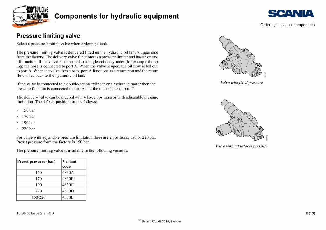
Valve with fixed pressure
339
126
Valve with adjustable pressure
Pressure limiting valveSelect a pressure limiting valve when ordering a tank.
The pressure limiting valve is delivered fitted on the hydraulic oil tank’s upper side from the factory. The delivery valve functions as a pressure limiter and has an on and off function. If the valve is connected to a single-action cylinder (for example dump-ing) the hose is connected to port A. When the valve is open, the oil flow is led out to port A. When the valve then closes, port A functions as a return port and the return flow is led back to the hydraulic oil tank.
If the valve is connected to a double-action cylinder or a hydraulic motor then the pressure function is connected to port A and the return hose to port T.
The delivery valve can be ordered with 4 fixed positions or with adjustable pressure limitation. The 4 fixed positions are as follows:
• 150 bar
• 170 bar
• 190 bar
• 220 bar
For valve with adjustable pressure limitation there are 2 positions, 150 or 220 bar. Preset pressure from the factory is 150 bar.
The pressure limiting valve is available in the following versions:
Preset pressure (bar) Variant code
150 4830A
170 4830B
190 4830C
220 4830D
150/220 4830E
© Scania CV AB 2015, Sweden
13:50-06 Issue 5 en-GB 8 (19)

Components for hydraulic equipmentOrdering individual components
346 2
34
Not activated connection
Hydraulic pumpIt is a prerequisite that one of the following power take-offs, EG650P, EG651P, EG652P or EG653P, is ordered if a hydraulic pump is to be fitted at the factory.
When ordering a pump from the factory, the engine speed is limited when the power take-off is activated. The speed depends on the pump and power take-off selected.
• The suction union and pressure connection are not included when the pump is or-dered but must be ordered separately.
• Pump activation is not connected at delivery. Connect the P-pipe to complete the installation.
Part information
Contact a Scania dealer for more information.
Designation Part number
Suction union 2" 2 072 190
Pressure connection 2 075 117
© Scania CV AB 2015, Sweden
13:50-06 Issue 5 en-GB 9 (19)

Components for hydraulic equipmentOrdering individual components
Ordering optionsPump displacement (cm3)
Type of pump Variant codes
Pump displace-ment
Type of pump
35 Gear pump 4803F 4802A
60 Gear pump 4803B 4802A
80 Gear pump 4803C 4802A
115 Gear pump 4803E 4802A
40 Piston pump 4803A 4802B
60 Piston pump 4803B 4802B
80 Piston pump 4803C 4802B
100 Piston pump 4803D 4802B
© Scania CV AB 2015, Sweden
13:50-06 Issue 5 en-GB 10 (19)

Components for hydraulic equipmentPiston pump flows
345 7
91
Piston pump flowsAll vehicles equipped with Scania’s hydraulic pumps have a factory set maximum engine speed (rpm).
Highest theoretical flow in high split
Highest permissible pressure for all piston pumps is 400 bar.
Maximum permissible engine speed (rpm)Automatically locked to maximum engine speed for activated power take-off.
Power take-off
Gear ratio Pump displacement (cm3)
40 60 80 100
EG650P 1.24 61 89 106 153
EG651P 1.58 78 94 110 171
EG652P 1.03 51 74 101 127
EG653P 1.29 63 92 105 159
Power take-off Pump displacement (cm3)
40 60 80 100
EG650P 1,200 1,200 1,050 1,200
EG651P 1,200 1,000 850 1,050
EG652P 1,200 1,200 1,200 1,200
EG653P 1,200 1,200 1,000 1,200
© Scania CV AB 2015, Sweden
13:50-06 Issue 5 en-GB 11 (19)

Components for hydraulic equipmentGear pump flows
327
100
Gear pump flowsHighest theoretical flow in high split
Maximum permissible engine speed (rpm)Automatically locked to maximum engine speed for activated power take-off.
Power take-off Gear ratio Pump displacement (cm3)
35 60 80 115
EG650P 1.24 51 91 106 168
EG651P 1.58 66 97 110 169
EG652P 1.03 43 76 101 139
EG653P 1.29 53 95 105 160
Highest permissible pressure (bar)
Continuous 230 230 205 205
Periodic 250 250 225 225
Power take-off Pump displacement (cm3)
35 60 80 115
EG650P 1,200 1,200 1,050 1,200
EG651P 1,200 1000 850 950
EG652P 1,200 1,200 1,200 1,200
EG653P 1,200 1,200 1,000 1100
© Scania CV AB 2015, Sweden
13:50-06 Issue 5 en-GB 12 (19)
Components for hydraulic equipmentTheoretical flows at different engine speeds
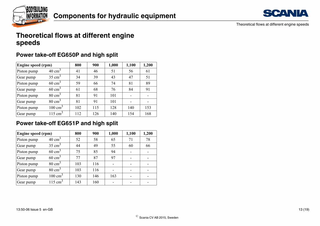
Theoretical flows at different engine speedsPower take-off EG650P and high split
Power take-off EG651P and high split
Engine speed (rpm) 800 900 1,000 1,100 1,200
Piston pump 40 cm3 41 46 51 56 61
Gear pump 35 cm3 34 39 43 47 51
Piston pump 60 cm3 59 66 74 81 89
Gear pump 60 cm3 61 68 76 84 91
Piston pump 80 cm3 81 91 101 - -
Gear pump 80 cm3 81 91 101 - -
Piston pump 100 cm3 102 115 128 140 153
Gear pump 115 cm3 112 126 140 154 168
Engine speed (rpm) 800 900 1,000 1,100 1,200
Piston pump 40 cm3 52 58 65 71 78
Gear pump 35 cm3 44 49 55 60 66
Piston pump 60 cm3 75 85 94 - -
Gear pump 60 cm3 77 87 97 - -
Piston pump 80 cm3 103 116 - - -
Gear pump 80 cm3 103 116 - - -
Piston pump 100 cm3 130 146 163 - -
Gear pump 115 cm3 143 160 - - -
© Scania CV AB 2015, Sweden
13:50-06 Issue 5 en-GB 13 (19)

Components for hydraulic equipmentTheoretical flows at different engine speeds
Power take-off EG652P and high split
Power take-off EG653P and high split
Engine speed (rpm) 800 900 1,000 1,100 1,200
Piston pump 40 cm3 34 38 42 46 51
Gear pump 35 cm3 28 32 36 39 43
Piston pump 60 cm3 49 55 61 67 74
Gear pump 60 cm3 50 57 63 69 76
Piston pump 80 cm3 67 76 84 92 101
Gear pump 80 cm3 67 76 84 93 101
Piston pump 100 cm3 85 95 106 117 127
Gear pump 115 cm3 93 105 116 128 139
Engine speed (rpm) 800 900 1,000 1,100 1,200
Piston pump 40 cm3 42 47 53 58 63
Gear pump 35 cm3 36 40 45 49 53
Piston pump 60 cm3 61 69 77 84 92
Gear pump 60 cm3 63 71 79 87 95
Piston pump 80 cm3 84 95 105 - -
Gear pump 80 cm3 84 95 105 - -
Piston pump 100 cm3 106 119 133 146 159
Gear pump 115 cm3 116 131 146 160 -
© Scania CV AB 2015, Sweden
13:50-06 Issue 5 en-GB 14 (19)
Components for hydraulic equipmentComplete installation from the factory
339
127
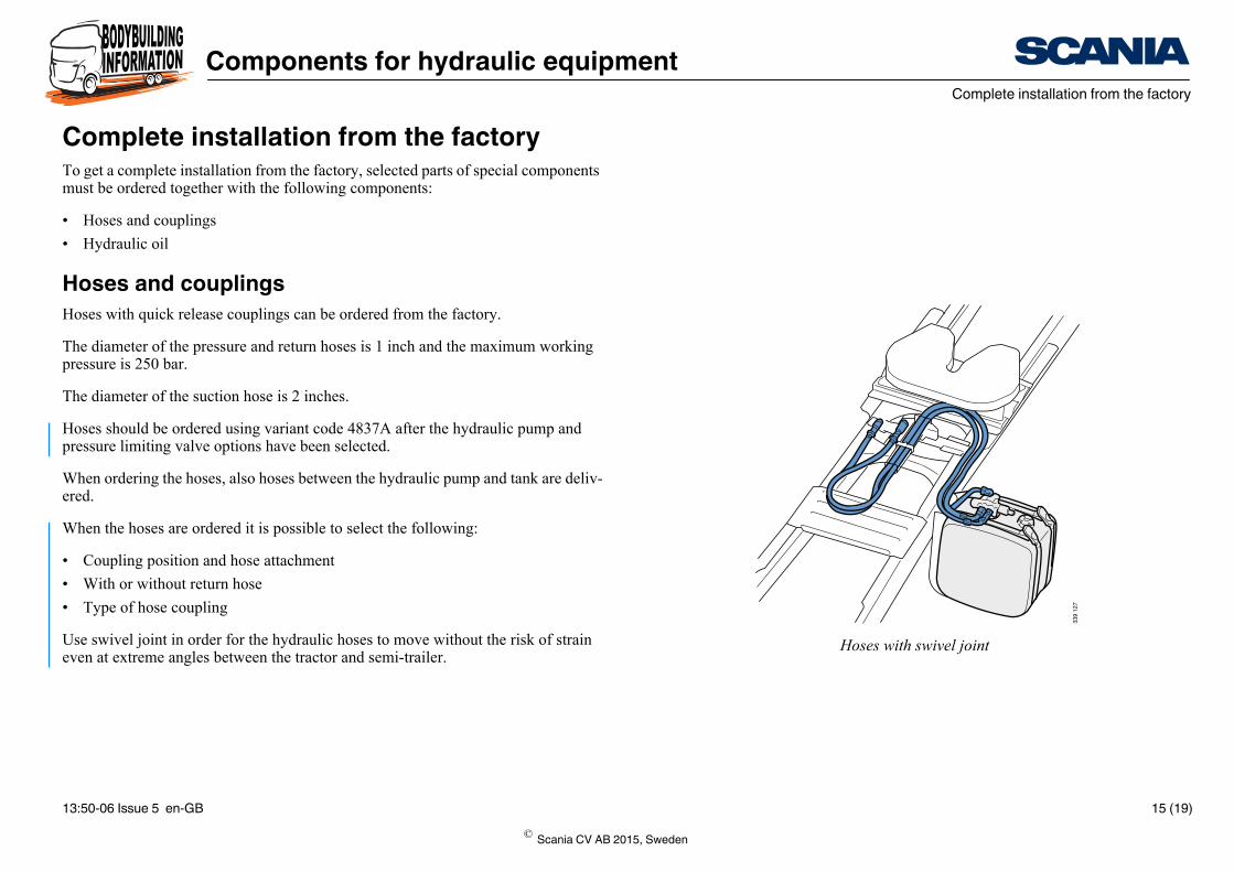
Hoses with swivel joint
Complete installation from the factoryTo get a complete installation from the factory, selected parts of special components must be ordered together with the following components:
• Hoses and couplings
• Hydraulic oil
Hoses and couplingsHoses with quick release couplings can be ordered from the factory.
The diameter of the pressure and return hoses is 1 inch and the maximum working pressure is 250 bar.
The diameter of the suction hose is 2 inches.
Hoses should be ordered using variant code 4837A after the hydraulic pump and pressure limiting valve options have been selected.
When ordering the hoses, also hoses between the hydraulic pump and tank are deliv-ered.
When the hoses are ordered it is possible to select the following:
• Coupling position and hose attachment
• With or without return hose
• Type of hose coupling
Use swivel joint in order for the hydraulic hoses to move without the risk of strain even at extreme angles between the tractor and semi-trailer.
© Scania CV AB 2015, Sweden
13:50-06 Issue 5 en-GB 15 (19)

Components for hydraulic equipmentComplete installation from the factory
Ordering optionsOption Alternative Variant
code
Position of hydraulic hose cou-pling
Swivel joint 4838A
Behind cab 4838B
Hydraulic hose, return With 4839A
Hydraulic hose coupling Screw 4840A
Push/pull 4840B
© Scania CV AB 2015, Sweden
13:50-06 Issue 5 en-GB 16 (19)

Components for hydraulic equipmentComplete installation from the factory
Ball valve
Recommendations for hydraulic oil are available in the document General informa-tion about power take-offs.
Hydraulic oilHydraulic oil can be ordered after ordering the hoses using variant code 4837A and when the hydraulic pump and pressure limiting valve options have been selected.
The hydraulic oil supplied from the factory is Q8 Heller VG 22.
Note:There is a risk for breakdown if the system is started without oil. Therefore, check before starting:
• That there is oil in the hydraulic oil tank (using the level indicator).
• Check that the ball valve for the suction pipe is open.
To achieve a good service life of the hydraulic pumps, it is important to renew the oil filter regularly and also change the hydraulic oil when necessary. The purity of the oil is directly related to the service life of the hydraulic system. To obtain the longest possible service life, Scania recommends a filtration of 10 µm (abs). Only use hy-draulic oils with anti-foaming and anti-wear additives.
Examples of tipper functions: With an ambient temperature of 35°C the hydraulic oil’s temperature becomes approx. 40°C for dumping. Hydraulic oil VG22 has 22 mm2/s (cSt) and therefore lies between 20 and 30 mm2/s (cSt).
A hydraulic oil with too high viscosity can cause the hydraulic system to be experi-enced as being sluggish as the oil must reach operating temperature before it becomes more viscous. This applies primarily to functions that are used in short cycles, for ex-ample dumping.
© Scania CV AB 2015, Sweden
13:50-06 Issue 5 en-GB 17 (19)

Components for hydraulic equipmentComplete installation from the factory
Ordering options
ViscosityThe hydraulic oil supplied from the factory is of the Q8 Heller VG22 type. When fill-ing your own oil, you should select VG32 for hot climates and VG22 for cold cli-mates. However, for dumping VG22 is quite sufficient also in hot climates as it does not have time to build up heat in the hydraulic system. For a tipper truck, the hydrau-lic oil normally has a 5°C higher temperature than the ambient temperature. For Sca-nia’s pumps, a viscosity of between 20 and 30 mm2/s (cSt) is recommended.
Option Alternative Variant code
Hydraulic oil With 4851A
© Scania CV AB 2015, Sweden
13:50-06 Issue 5 en-GB 18 (19)

Components for hydraulic equipmentConfiguration adapted hydraulic system
More information on ordering controls is available in the Ordering individual com-ponents section of this document.
Configuration adapted hydraulic systemIt is possible to order a complete solution for the control of hydraulic equipment for vehicles with the wheel configurations 6x2, 6x2/4 and 6x2/2. The following is in-cluded in the installation:
• Gear pump, 82 cm³
• Tilt valve, 170 bar
• Combined tank 150-150 litres, front diesel and rear oil The rear tank is filled with 145 litres of oil.
• Hydraulic oil, Q8 Heller 22
• Hose coupling screw
• Without return hose
The installation is not supplied with control.
Ordering options
Contact a Scania dealer for more information.
Option Alterna-tive
Variant code
Wet kit FFU 6x2/4 5363A
Wet kit FFU 6x2/2 5363B
Wet kit FFU 6x2 5363C
© Scania CV AB 2015, Sweden
13:50-06 Issue 5 en-GB 19 (19)