components and repair manual - amazon s3 · components and repair manual model mcl-48/54 ......
TRANSCRIPT

COMPONENTS ANDREPAIR MANUAL
MODEL McL-48/54EARTH BORING MACHINE
PART NO. 4810000
Machine Serial No.:48/5406060608 - Present
Manual Part No.: E250410
2006 Perimeter Rd. Greenville, SC 29605Toll Free: 800-435-9340 - Phone: 864-277-5870
Fax: 864-235-9661 - www.mightymole.comemail: [email protected]
Machine Serial #_________________________________________________________
Purchased &Serviced Thru: __________________________________________________________
Purchase Date: _________________________________________________________
© 2008 by McLaughlin Group, Inc. All rights reserved. No part of this manualmay be reproduced in any form or by any means without prior written permission from theMcLaughlin Group, Inc.. Revision Date: 01/18/08

WARNING: Battery posts, terminals and releated accessories contain lead and leadcompounds, chemicals known to the State of California to cause cancer and birthdefects or other reproductive harm. Wash hands after handling.
WARNING: The engine exhaust from this product contains chemicalsknown to the State of California to cause cancer and birth defects or otherreproductive harm.
DESCRIPTION PAGE
Machine Specifications and System Operating Specifications 1.1.0
Fill Points, Filters and Routine Maintenance 2.1.0Decal Placement 2.2.0
Machine Assemblies, Parts Details 3.0Jacking Station Assembly 3.1.0Carriage Assembly 3.2.0Roll Bar Assembly 3.3.0Powertrain Assembly 3.4.0Dog Plate Assembly 3.5.0Casing Pusher Assemblies & Adapters 3.6.0Track Assembly 3.7.0Hydraulic Tank Assembly 3.8.0Fuel Tank Assembly 3.9.0
Machine Operating Systems 4.0Hydraulic System (Hoses and Fittings) 4.1.0Electrical System (Wiring Diagram) 4.2.0
Machine Component Parts Details 5.0Engine (Operation and Parts) 5.1.0Gearbox (Parts) 5.2.0Transmission (Parts) 5.3.0Hydraulic Pump Coupling 5.4.0Hydraulic Clutch 5.5.0Hydraulic Thrust Cylinder 5.6.0Hydraulic Dog Plate Cylinder 5.7.0Hydraulic Valve Handle (Parts) 5.8.0
Hydraulic Clutch 6.0Operation (Cold Weather Procedures) 6.1.0Troubleshooting 6.2.0
McL 48/54
McLaughlin Group, Inc. reserves the right to make changes at any time without notice or obligation.
TABLE OF CONTENTS

TABLE OF CONTENTS
DESCRIPTION PAGE
Service and Repair Instructions 7.0Machine Split 7.1.0Coupling (Transmission/Gearbox) 7.2.0Hydraulic Pump Coupling 7.3.0Dog Plate 7.4.0Cylinder 7.5.0Hydraulic Clutch 7.6.0Pump Settings and Adjustments 7.7.0Main Thrust Valve 7.8.0
Deutz Emission Warranties Insert
McL 48/54
McLaughlin Group, Inc. reserves the right to make changes at any time without notice or obligation.

MACHINE SPECIFICATIONSMcL 48/54
SPECIFICASPECIFICASPECIFICASPECIFICASPECIFICATIONS OF MCL-48/54TIONS OF MCL-48/54TIONS OF MCL-48/54TIONS OF MCL-48/54TIONS OF MCL-48/54
EARTH BORING MACHINEEARTH BORING MACHINEEARTH BORING MACHINEEARTH BORING MACHINEEARTH BORING MACHINEBoring Range: ENGLISH METRICCased Bore 16”-54” 41 cm-138 cm
Engine: Air cooled, in-line 6 cylinder diesel, turbo charged12 VDC electric system162 hp ISO max. (121 kW) @ 2,500 RPM139 hp continuous (104 kW) @ 2,500 RPM
Transmission: 5 forward speeds, 1 reverse
Clutch: Hydraulic clutch with Operator Presence Control Switch
Final Drive: Planetary reduction, 4” hex chuck (10 cm)
Auger Torque: 170,000 ft/lbs. peak(230,000 Nm) in 1st gear
Forward Thrust: 950,000 lbs. (4228 kN) max @ 5,000 psi (345 bar) with infinitely adjustable thrust speed
Dog Plate: Hydraulically activated with dog pin indicators and fast feed
Hydraulic Parameters: 5,000 psi (345 bar) max. system, pressure comp. pump with load sense, 48 gpm (182) lpm @ 2,500 RPM, hydraulic tank capacity 58 gallons (219 L), oil level sight gauge, temp. and cleanout ports.
Hydraulic Filtration: 1. Suction strainer - 100 mesh 2. In-take return filter - 12 micron replaceable element 3. 10 micron spin-on return filter
Fuel Tank: 15 gallon (57 L) capacity with sight gauge
DimensionsMachine: 74” (188 cm) wide x 12’6” (3.8 m) long x 64” (163 cm) high
Jacking Station: 9,750 lbs. (4,422 kg)
Carriage: 4,200 lbs. (1,905 kg)
Casing Pusher: 1,300 lbs. (590 kg)
Track: 66” (168 cm) wide x 9’ (274 cm) long x 14.5” (37 cm) high - 1,500 lbs.(680 kg)
5’ Track Extension: 800 lbs. (365 kg)
Machine Centerline: 32.5” (83 cm)
Push Plate: 440 lbs. (200 kg)
1.1.1
McLaughlin Group, Inc. reserves the right to make changes at any time without notice or obligation.

SYSTEM OPERATION SPECIFICATIONSMcL 48/54
Engine1. Speed Idle: 1050-1150 Max.: 2400-25002. Oil SAE 5W-30 or refer to Engine Manual3. Fuel Commercially available diesel fuel with less than
0.5% sulphur content. Refer to Engine Manual.4. Fuel Tank Capacity ~ 15 Gallons (56 l.)
Gearbox 80-90 wt. gear oil with EP additivesCapacity ~ 2 Gallons (8 l.)
Transmission Synthetic 50 wt. transmission fluidCapacity 1.5 Gallons (5.9 l)
Hydraulic System1 Hydraulic Pump Pressure Compensated w/ Load Sense
Compensator Setting: ~ 5000 psiStand-by Setting: ~ 250-300 psi
2. Hydraulic Control Valve Electric-proportional w/ Manual operation Main Thrust Sysem Relief Valve Setting: ~ 5100 + psi
3. Hydraulic Track Brake Setting: ~ 800 psi (Secondary System)
4. Hydraulic Dog Pins Setting: ~ 800 psi (Secondary System)
5. Hydraulic Clutch Setting: 225 psi (Secondary System)
6. Hydraulic Fluid: 76 Unax AW #46 or equivalent
ISO grade 46, hydraulic fluid with anti-wear additives. Containsadditives that provide oxidation resistance, rust and corrosionprotection, foaming resistance and have water separatingcharacteristics. Consult McLaughlin Group, Inc. forrecommendations on cold weather operation.
7. Hydraulic Tank Capacity ~ 60 Gallons (225 l.)
Electrical System1. Battery 12V DC w/ 700 CCA Max.2. Hydraulic Control Valve 12V DC w/ Valve Driver Card and Potentiometer Main Thrust System .6 Amps to shift valve, 1.8 Amps to shift fully3. Preheat System 12 V DC w/ manual delay4. Fuses 12V DC, Inline and panel, SFE and ATO styles5. Cartridge Valves 12V DC at 1-3 Amps
*Specifications subject to change without notice or obligations.
1.1.2

FILTERS AND FILL POINTSMcL 48/54
1. Engine Oil Fill - Use only manufacturer’sapproved oils (Reference section 5.1 EngineOperation).
3. Oil Filter - Use only manufacturer approvedengine filter. Reference section 5.1 EngineOperations for specifications and maintenance.
2. Dip Stick - Check daily with engine warm.Fill as needed to the upper dash mark on the
4. Fuel Filter - Use only manufacturer’s approvedreplacement filters. (Reference section 5.1 EngineOperation for maintenence schedule).
5. Fuel Level - Fill as needed with brandedgrades of diesel fuel with a sulfur content below0.5% (Reference section 5.1co Engine Operation for approved fuel specifications).
2.1.1
1
2
3, 4
5

FILTERS AND FILL POINTSMcL 48/54
7. Hydraulic Oil Filter - Replace all filterswith every engine oil change or if required by filterindicator, whichever comes first. Clean or replacein-tank suction strainer annually when oil is changed.
9. Transmission Oil Fill - Fill to checkpoint with #50 synthetic transmission fluid.Change after first 50 hours of use, then every1000 hours or annually.
8. Gearbox Oil Fill - Fill to check point.Change after first 50 hours of use, then every1000 hours or annually.
6. Hydraulic Oil Level - Fill to 1 1/2” below topof tank (with cylinders retracted). Change oil afterfirst 1000 hours of use, then annually.
2.1.2
6
7
8
910. Engine Air Cleaner - Check air cleanerelement condition using the filter indicator.Clean or replace element when indicator is in the “red zone.” Clean or replace when requiredby the filter indicator or annually, which evercomes first. Reference pages 5.1.23 & 5.1.24 of the Engine Operation section for more information.

DECAL PLACEMENTMcL 48/54
2.2.1
DECAL APPLICATION:REMOVE OIL AND DIRT FROM SURFACE.MAKE SURE SURFACE IS SMOOTH.
J000
100
- DAN
GER
ENTA
NG
LEM
ENT
HAZ
ARD
J800
030
- IN
STR
UC
TIO
NO
PER
ATO
R’S
MAN
UAL
PLAC
E O
N M
ANU
AL B
OX
J000
080
- WAR
NIN
GD
O N
OT
GO
FO
RW
ARD
J000
020
- WAR
NIN
GAV
OID
DEA
TH
J000
210
- WAR
NIN
GLO
CAT
E U
TILI
TIES

DECAL PLACEMENTMcL 48/54
2.2.2
J000
160
- CAU
TIO
NPI
NC
H P
OIN
T2
REQ
UIR
ED
J802
000
- WAR
NIN
GR
OTA
TIN
G S
HAF
T
J000
080
- WAR
NIN
GD
O N
OT
GO
FO
RW
ARD
J000
200
- DAN
GER
MAC
HIN
E PA
RTS
J000
120
- DAN
GER
RO
TATI
NG
BLA
DES

PAGE LEFT BLANK

JACKING STATION ASSEMBLYMcL 48/54
3.1.1

JACKING STATION ASSEMBLYMcL 48/54
** - Use exact grade specified - DO NOT change from original equipment.
3.1.2
#METI .YTQ REBMUN NOITPIRCSED1 1 1010184 noitatSgnikcaJ2 4 0310184 nwoDdloH
8 7410084 niPnwoDdloH8 560043U niPhcniL"52.
3 4 001000W relloRmaC4 8710084 recapSrelloRmaC4 185100U 05.5X7-52.1CH,wercS4 170012U 7-52.1YNkcoL,tuN
4 1 0111084 ylbmessAekarBkcarT1 1111084 rednilyCekarBkcarT1 3111084 kcolBgnitnuoM4 001012U 005.kcoL,rehsaW4 028000U 52.1X31-005.CH,wercS1 2111084 notsiP2 080000U 52.1X02-052.CH,wercS1 512002W 632#gniR-O1 4111084 etalPpotS4 060012U 573.kcoL,rehsaW4 024000U 00.1X61-573.CH,wercS
5 4 9410084 niPegairraC4 9210184 niProhcnA8 4310184 rehsaWytuDyvaeH'2/18 **385100U 8G05.6X8-1CH,wercS
6 1 5310184 tnuoMtcennocsiDkciuQ4 044000U 8G52.1X61-573.CH,wercS4 006002U 573.talF,rehsaW4 060012U 573.kcoL,rehsaW

CARRIAGE ASSEMBLYMcL 48/54
3.2.1

CARRIAGE ASSEMBLYMcL 48/54
3.2.2
#METI .YTQ REBMUN NOITPIRCSED1 1 1020184 egairraC2 1 1620184 knaTleuF
3 7720084 tnuoMknaTleuF5 010061U 61-573.maJ,tuN5 060002U 573.talF,rehsaW
3 1 0070184 knaTciluardyH4 2670084 tnuoMknaTciluardyH8 002021U 61-573.kcoLzihW,tuN
4 1 0720184 tekcarByrettaB4 002100U 00.2X11-526.CH,wercS4 081001U 11-526.xeH,tuN4 041002U 526.talF,rehsaW1 7720184 nwoDdloHyrettaB2 081000U 57.X81-213.CH,wercS2 040012U 213.kcoL,rehsaW2 060002U 573.talF,rehsaW1 030004X erusolcnEyrettaB1 020004X evitomotuAyrettaB
ROLL BAR ASSEMBLYMcL 48/54
3.3.1

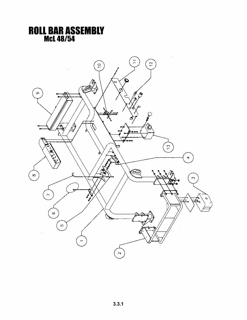
ROLL BAR ASSEMBLYMcL 48/54
3.3.2
Optional Equipment(Available upon request)
1 1 1820184 lenaPlortnoC,dleihSladnaV
ITEM# QTY. NUMBER DESCRIPTION1 1 4810230 Roll Cage
16 U001420 Screw, HC .750-10 X 2.5016 U210160 Washer, Lock .75016 U100200 Nut, Hex .750-10
2 1 4810232 Pump Roll Cage12 U000860 Screw, HC .500-13 X 1.7512 U200100 Washer, Flat .50012 U100120 Nut, Hex .500-13
3 1 4800847 Winch1 480084703 Freewheel-Engage Dial1 4810256 Winch Seal Plate3 U000840 Screw, HC .500-13 X 1.503 U210100 Washer, Lock .5003 U100120 Nut, Hex .500-13
4 1 4800298 Left Side Muffler Bracket2 4800290 Muffler Isolator4 U000817 Screw, HC .500-13 X 1.00 G86 U200100 Washer, Flat .5004 U210100 Washer, Lock .500
5 1 4800297 Right Side Muffler Bracket2 4800290 Muffler Isolator4 U000817 Screw, HC .500-13 X 1.00 G86 U200100 Washer, Flat .5004 U210100 Washer, Lock .500
6 1 4800299 Mirror1 4800288 Mirror Bracket
7 2 4800295 Muffler Hook4 U120200 Nut, Whiz, Lock
8 1 4801215 Operator Console4 U000040 Screw, HC .250-20 X .7504 U210020 Washer, Lock .2504 U200020 Washer, Flat .250
9 1 4800280 Toolbox4 U000820 Screw, HC .500-13 X 1.254 U210100 Washer, .5004 U100120 Nut, Hex .500-1
ITEM# QTY. NUMBER DESCRIPTION10 1 4801300 Drag Brake Handle Assembly
1 4801301 Drag Brake Handle Bracket2 U200040 Washer, Flat .3122 U210040 Washer, Lock .3122 U000160 Screw, HC .312-18 X .5001 4801333 Lever1 2050057 Lever Grip1 U000220 Screw, HC .312-18 X 1.251 U210040 Washer, Lock .3121 U200040 Washer, Flat .3121 U210041 Nut, NyLock .312-18
11 1 4810255 Console Cover Plate4 U000040 Screw, HC .250-20 X .7504 U200020 Washer, Flat .2504 U210020 Washer, Lock .2501 4800784 Thrust Pressure Gauge, 5000 psi1 T720012 Clutch Pressure Gauge, 600 psi1 4800829 Power Outlet1 X000400 Tachometer, Operator Switch1 480084702 Winch Operating Switch Knob1 480024701 Winch Operating Switch
12 1 3600116 Throttle Control1 3600115 Throttle Cable1 3600131 Throttle Cable Bulkhead Adapter
13 1 4800778 Control Valve4 U030110 Screw, SFH .437—14 X 1.251 4810710 Valve Handle1 3610211 Valve Adapter Plate3 U000817 Screw, HC .500-13 X 1.00 G83 U210100 Washer, Lock .5003 U200100 Washer, Flat .50

POWERTRAIN ASSEMBLY HYDRAULIC PUMPDETAILMcL 48/54
3.4.1

POWERTRAIN ASSEMBLY HYDRAULIC PUMPDETAILMcL 48/54
3.4.2
91 1 1530084 ylbmessArevoCdrauGtnorFN/PzteuD
8083-030 recapSxeH7083-030 recapSebuT9083-030 tekcarBtroppuS0819-322 tekcarBretlaH5973-030 drauGtleB8493-633 rehsaW2232-111 C4A02X8M7104-osISCHH4421-111 C4A002X8M4104-osISCHH
02 1 0630084 gnilpuoCpmuPciluardyH12 1 1630084 esoHekatnIrofraBtroppuS
1 041001U 31-005.daoL,tuN1 040022U 057.ratS,rehsaW1 020061U 31-057.maJ,tuN1 0830084 tekcarBesoHegraL2 002021U 61-573.kcoL,zihW,tuN
22 1 1070084 etalPgnitnuoM4 2232-111 C4A02X8M-OSISCHH
32 1 2070084 etalPtoliP
1 584100U 8G05.3X01-057.CH,wercS3 024100U 05.2X01-057.CH,wercS4 061012U 057.kcoL,rehsaW
42 1 9670084 pmuPciluardyH4 001012U 005.kcoL,rehsaW4 009000U 05.2X31-005.CH,wercS
#METI .YTQ REBMUN NOITPIRCSED
1 1 3030084 enignEztueDrednilyC63192 1 4230084 mrAelbaCelttorhT
1 095100U mm51X52.1Xmm8CH,wercS1 8011084 kcoLelbbaC1 010420U 005.X02-052.teS,wercS
3 1 8230084 daehkluBelbaC,tekcarB1 1310063 tiKretpadAdaehkluB1 5110063 elbaCelttorhT
4 1 5630084 dioneloSnwoDtuhS5 1 9730084 sgniRlaeStsuahxE6 1 4630084 woblEdlofinaMtsuahxE
3 208000U 052.2X41-834.CH,wercS3 080012U 834.kcoL,rehsaW3 001001U 834.xeH,tuN
7 1 4830084 esoHelbixelFtsauhxE8 2 1430084 tekcarBtsuahxErelffuM
2 502021U 81-213.kcoL,zihW,tuN9 1 8630084 ediSrelffuMtsuahxE01 1 1830084 relffuM11 1 8030184 woblEtsuahxErelffuM21 1 8730084 pacniaR31 1 2830084 woblErenaelCriA
1 1400024 rotacidnIretliFriA41 1 3830084 esoHelbixelFrenaelCriA
1 9630084 retpadArenaelCriA51 1 8330084 renaelCriA
108330084 paCrenaelCriA208330084 tnemelEretliFretuOrenaelCriA308330084 tnemelEretliFrennIrenaelCriA
61 1 01300184 tnemdleWtnuoMenignE.S.R1 11300184 tnemdleWtnuoMenignE.S.L4 646100U 03X57.1Xmm21CH,wercS4 246100U 54X57.1Xmm21CH,wercS8 322012U mm21kcoL,rehsaW
71 1 2120084 tnuoMenignEraeR.S.R1 5120084 tnuoMenignEraeR.S.L8 246100U 03X57.1Xmm21CH,wercS8 322012U mm21kcoL,rehsaW
81 4 2530084 srotalosIenignE4 020100U 05.5X31-005.CH,wercS8 608000U 57.X31-005.CH,wercS21 001002U 005.talF,rehsaW21 021021U 31-005.kcoL,tuN

TRANSMISSION DETAILMcL 48/54
POWERTRAIN ASSEMBLY
3.4.3
1
3
4 2
6
7
5
8
9
10
11
12
13
14
15
16
18
17
19

TRANSMISSION DETAILMcL 48/54
POWERTRAIN ASSEMBLY
3.4.4
ITEM # QTY. NUMBER DESCRIPTION1 1 4800346 Transmission2 1 4810312 Transmission Support Weldment
4 U001360 Screw, HC .750-10 X 1.504 U210160 Washer, Lock .7505 U001642 Screw, HC 12mm X 1.75 X 30mm5 U210223 Washer, Lock 12mm
3 1 4810346 Coupling Guard3 U000440 Screw, HC .375-16 X 1.253 U200600 Washer, Flat .375
4 1 480034601 Transmission Shaft Rod1 480034602 Transmission Shaft Knob
5 1 4800369 Bell Housing2 4810355 Bell Housing Side Cover (Not Shown)1 4000335 Cover Plate, Bottom (Not Shown)12 U001620 Screw, HC 10mm X 1.50 X 25mm12 U210220 Washer, Lock 10mm
6 1 4810322 Eng/Trans Support Spacer7 1 4800844 Enclosure, Clutch Relay
4 8030438 Screw, PH 10-24 X .7501 4800336 Bracket, Enclosure, Clutch Solenoid
8 1 4810385 Clutch Sleeve9 1 4810379 Ant-Rotation Bracket10 1 4810399 Hydraulic Clutch - Model 21111 1 4810398 Clutch Drive Shell12 1 4810382 Bell Housing Spacer13 1 4800387 Bearing14 1 4810384 Bearing Carrier15 1 4801345 Engine Vent16 1 4800841 Junction Box
2 U000060 Screw, HC .250-20 X 1.002 U000020 Screw, HC .250-20 X .5004 U210020 Washer, Lock .250
17 1 4800371 Mount Plate2 U210240 Screw, HC M10 X 30mm2 U210220 Washer, Lock 10mm
18 1 X000047 V-Belt Solenoid1 4801309 Bracket, V-Belt Solenoid2 U000040 Screw, HC .250-20 X .7502 U200020 Washer, Flat .25
19 1 4810389 Clutch Capture Spacer6 U030050 Screw, SFH .3125-18 x .750

GEARBOX DETAILPOWERTRAIN ASSEMBLYMcL 48/54
3.4.5

GEARBOX DETAILPOWERTRAIN ASSEMBLYMcL 48/54
3.4.6
Optional Equipment(Available upon request)1 1 0630184 niartrewoP,dleihSladnaV
#METI .YTQ REBMUN NOITPIRCSED1 1 2030084 xobraeG
4 7030084 tresnIdedaerhTetalPlaeSxobraeG2 1 3010084 gniRretpadAxobraeG
04 044100U )nwohStoN(00.2x01-057.CH,wercS04 061012U )nwohStoN(057.kcoL,rehsaW
3 1 6030084 etalPlaeSxobraeG4 010030U 365.X02-052.HFS,wercS
4 2 591002W gniR-O5 1 8430084 retpadAtupnI,tfahS
4 083100U 00.2X01-057.CH,wercS4 061012U 057.kcoL,rehsaW1 140024U yeK
6 1 4330184 egnalFdnuoRgnilpuoC2 030042U 05.1x61-573.teS,wercS
7 1 1330184 rebmeMretneC8 1 2330184 etalPretpadAgnilpuoC
2 052010U 57.3X31-005.HSH,wercS2 162010U 57.4X31-005.HSH,wercS2 041001U 31-005.xeH,tuN
9 1 3330184 egnalFnoinapmoC01 1 5930084 ksiDekarBgarD
4 011012U 005.C-H,rehsaW4 030070U 52.3X31-005..tP21,BC,wercS
11 1 8330184 tnuoMekarBgarD2 001002U 005.talF,rehsaW2 510021U 02-005.colyN,tuN
21 2 1310063 tiKretpadAdaehkluBbuHdleiF1:sniatnoCmaJ,tuN2
31 1 6330184 kcolBgnitnuoMekarBgarD41 1 6031084 dnaBekarB51 1 3031084 kcoLelbaCdnaBekarB
010420U puCNK005.X02-052.teS,wercS61 1 551220U 00.1x573.redluohS,wercS71 1 5110063 elbaCelttorhT

DOG PLATE ASSEMBLYMcL 48/54
3.5.1

DOG PLATE ASSEMBLYMcL 48/54
3.5.2
#METI .YTQ REBMUN NOITPIRCSED1 1 5340084 etalPgoD2 2 0140084 niPgoD3 2 060006U gnirpSnoisserpmoCniPgoD4 2 070000W relloRetalPgoD
2 8140084 recapSrelloR2 505100U 00.4X01-057.CH,wercS4 061002U 057.egraL,talF,rehsaW2 002001U 01-057.CH,tuN
5 2 8080084 hctiwSetalPgoD6 2 7340084 tnuoMhctiwS
4 060000U 00.1X02-052.CH,wercS4 020001U 02-052.xeH,tuN4 020002U 052.talF,rehsaW
7 3 0340084 niPrednilyC8 1 0171084 rednilyCniPgoD
2 505100U 00.4X01-057.CH,wercS9 1 1040184 xoBrevoCrednilyC
1 5240084 revoCpoT8 004000U 057.X61-573.CH,wercS8 060012U 573.kcoL,rehsaW4 004000U 057.X61-573.CH,wercS4 060002U 573.talF,rehsaW
01 1 2140084 xoBteltuO1 3140084 revoCteltuO1 4140084 temmorGteltuO2 060000U 00.1X02-052.CH,wercS2 020012U 052.kcoL,rehsaW2 020002U 052.talF,rehsaW2 001021U 02-052.kcoL,tuN

54” CASING PUSHER/SPOIL EJECTORMcL 48/54
3.6.1

Optional Equipment(Available upon request)
54” CASING PUSHER/SPOIL EJECTORMcL 48/54
3.6.2
6 081008A "81,tiKretpadA002008A "02,tiKretpadA042008A "42,tiKretpadA003008A "03,tiKretpadA063008A "63,tiKretpadA024008A "24,tiKretpadA084008A "84,tiKretpadA021020U )d'qeR3(05.3x01-057.QS,wercS
7 S02008A retpadA"02,eohSS42008A retpadA"42,eohSS03008A retpadA"03,eohSS63008A retpadA"63,eohSS24008A retpadA"24,eohSS84008A retpadA"84,eohS088000U )d'qeR4(00.2X31-005.CH,wercS001012U )d'qeR4(005.kcoL,rehsaW021001U )d'qeR4(31-005.xeH,tuN
#METI .YTQ REBMUN NOITPIRCSED
1 1 1050184 etelpmoC,rehsuPgnisaC"454 9210184 sniProhcnA4 4310184 nwoDeiT4 075100U 5G00.5X8-1CH,wercS
2 1 4150084 rooDliopS1 0550084 doRegniH1 510023U 00.1X521.rettoC,niP
3 1 5150084 kcuhCxeH"421 485100U 05.3X21-521.1CH,wercS21 012012U 521.1kcoL,rehsaW
4 1 6250084 ylbmessAelddaP"455 1 0250084 elddaS
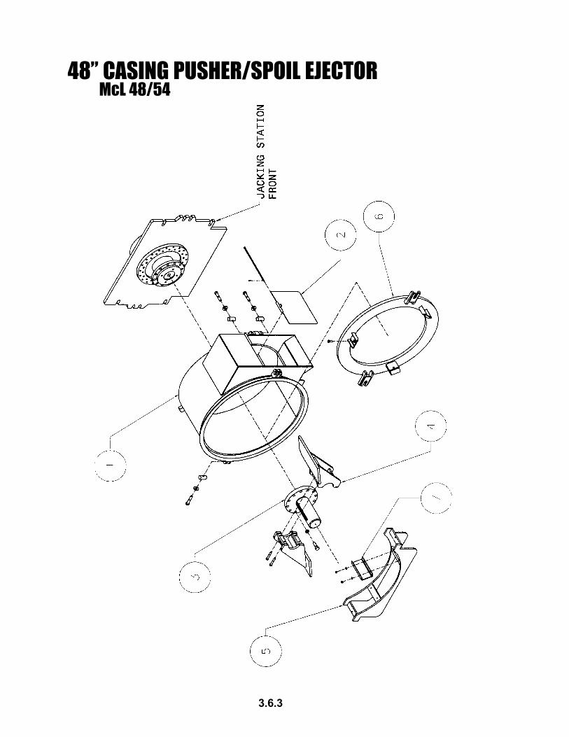
48” CASING PUSHER/SPOIL EJECTORMcL 48/54
3.6.3

48” CASING PUSHER/SPOIL EJECTORMcL 48/54
3.6.4
Optional Equipment(Available upon request)
6 081007A "81,tiKretpadA002007A "02,tiKretpadA042007A "42,tiKretpadA003007A "03,tiKretpadA063007A "63,tiKretpadA020074A "24,tiKretpadA021020U )d'qeR3(05.3x01-057.QS,wercS
7 S02007A retpadA"02,eohSS42007A retpadA"42,eohSS03007A retpadA"03,eohSS63007A retpadA"63,eohSS24007A retpadA"24,eohS088000U )d'qeR4(00.2X31-005.CH,wercS001012U )d'qeR4(005.kcoL,rehsaW021001U )d'qeR4(31-005.xeH,tuN
#METI .YTQ REBMUN NOITPIRCSED
1 1 1250184 etelpmoC,rehsuPgnisaC"844 9210184 sniProhcnA4 4310184 nwoDeiT4 075100U 5G00.5X8-1CH,wercS
2 1 4150084 rooDliopS1 0550084 doRegniH1 510023U 00.1X521.rettoC,niP
3 1 5150084 kcuhCxeH"421 485100U 05.3X21-521.1CH,wercS21 012012U 521.1kcoL,rehsaW
4 1 6250084 ylbmessAelddaP"455 1 0250084 elddaS

60” ADAPTERMcL 48/54
3.6.5

60” ADAPTERMcL 48/54
3.6.6
����� ���� ���� � ��������
� � ������� ����� ��� � ������� ���������������� � ������� �������������������

MASTER TRACK ASSEMBLYMcL 48/54
3.7.1

MASTER TRACK ASSEMBLYMcL 48/54
3.7.2
#METI .YTQ REBMUN NOITPIRCSED1 3 2360084 kcarT2 1 1360084 kcarTnoisnetxE3 1 0260084 etalPhsuP4 04 024100U 05.2X01-57.CH,wercS5 04 061012U 057.kcoL,rehsaW6 04 002001U 01-057.xeH,tuN7 1 5460084 raBrohcnA8 2 8460084 niPraBrohcnA
2 020023U 05.1X521.rettoC,niP9 1 0560084 elkcahSraBrohcnA
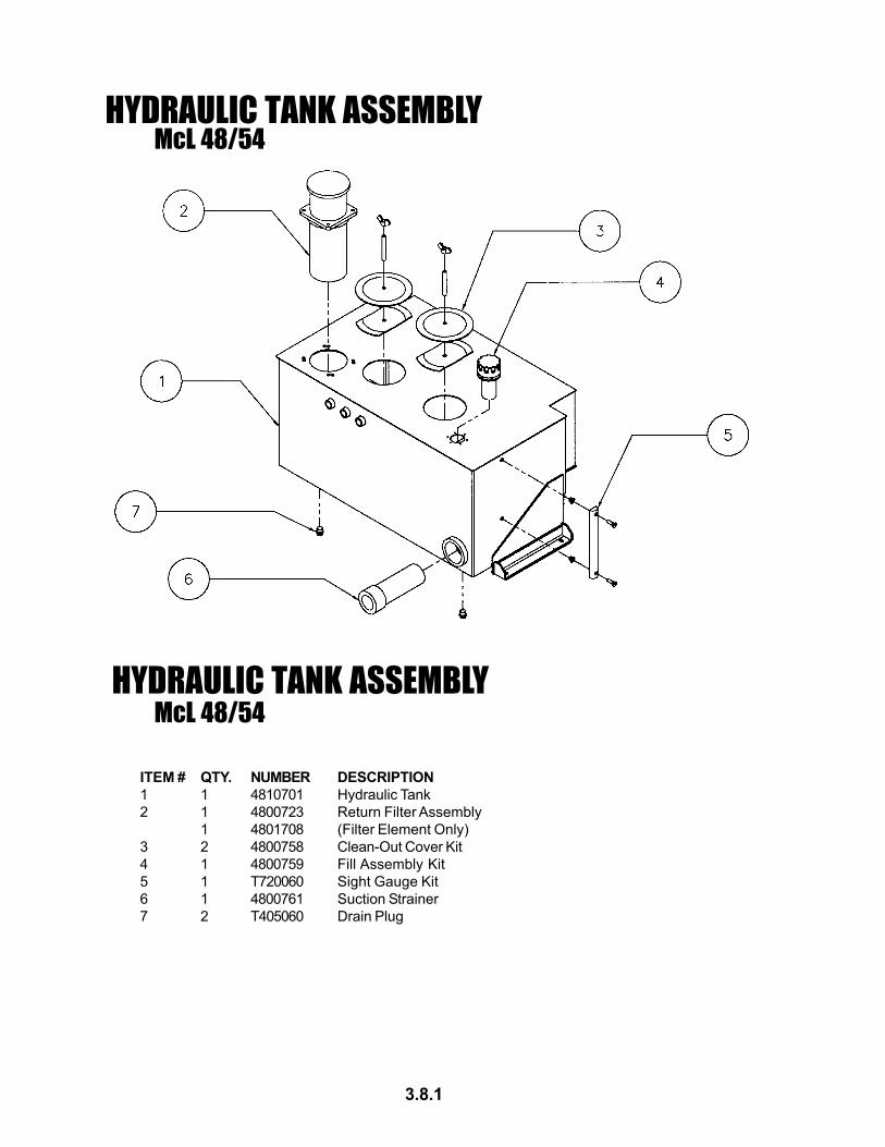
HYDRAULIC TANK ASSEMBLYMcL 48/54
HYDRAULIC TANK ASSEMBLYMcL 48/54
3.8.1
ITEM # QTY. NUMBER DESCRIPTION1 1 4810701 Hydraulic Tank2 1 4800723 Return Filter Assembly
1 4801708 (Filter Element Only)3 2 4800758 Clean-Out Cover Kit4 1 4800759 Fill Assembly Kit5 1 T720060 Sight Gauge Kit6 1 4800761 Suction Strainer7 2 T405060 Drain Plug

FUEL TANK ASSEMBLYMcL 48/54
FUEL TANK ASSEMBLYMcL 48/54
3.9.1
#METI .YTQ REBMUN NOITPIRCSED1 1 1620184 knaTleuF2 1 8720084 tiKpaCleuFelbakcoL3 1 6000108 tiK"6,eguaGthgiS

HYDRAULIC SYSTEMMcL 48/54
CARRIAGE
4.1.1
See
page
4.1
.2 fo
r fitt
ings
and
com
pone
nts
callo
ut
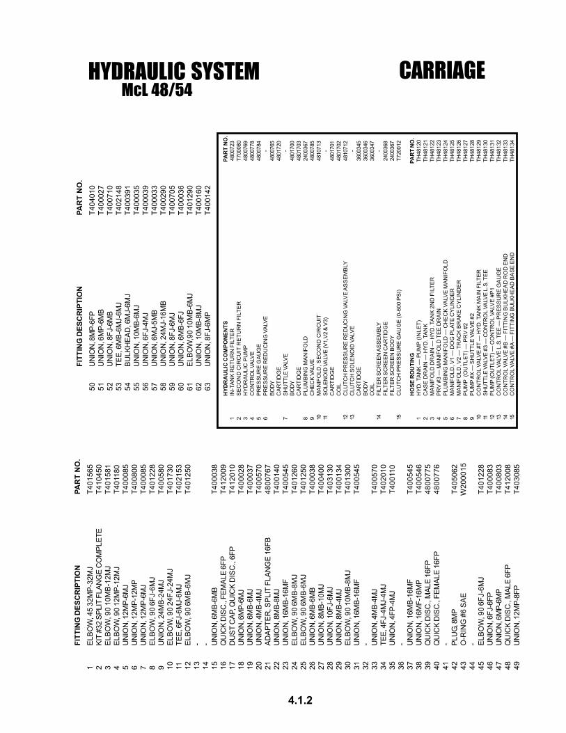
HYDRAULIC SYSTEMMcL 48/54
CARRIAGE
4.1.2
FITT
ING
DES
CR
IPTI
ON
PAR
T N
O.
50U
NIO
N, 8
MP-
6FP
T404
010
51U
NIO
N, 6
MP-
6MB
T400
027
52U
NIO
N, 8
FJ-6
MB
T400
710
53TE
E, 6
MB-
6MJ-
6MJ
T402
148
54BU
LKH
EAD
, 6M
J-6M
JT4
0039
155
UN
ION
, 10M
B-6M
JT4
0003
556
UN
ION
, 6FJ
-4M
JT4
0003
957
UN
ION
, 6M
J-5M
BT4
0003
358
UN
ION
, 24M
J-16
MB
T400
290
59U
NIO
N, 8
FJ-6
MJ
T400
705
60U
NIO
N, 6
MB-
6FJ
T400
036
61EL
BOW
,90
10M
B-6M
JT4
0129
062
UN
ION
, 10M
B-8M
JT4
0016
063
UN
ION
, 8FJ
-6M
PT4
0014
2
HYD
RA
ULI
C C
OM
PON
ENTS
PAR
T N
O.
1IN
-TA
NK
RE
TUR
N F
ILTE
R48
0072
32
SE
CO
ND
CIR
CU
IT R
ETU
RN
FIL
TER
T700
080
3H
YD
RA
ULI
C P
UM
P48
0076
94
CO
NTR
OL
VALV
E48
0077
85
PR
ES
SU
RE
GA
UG
E48
0078
46
PR
ES
SU
RE
RE
DU
CIN
G V
ALV
E-
BOD
Y48
0076
5C
AR
TID
GE
4801
720
7SH
UTT
LE V
ALVE
-BO
DY
4801
700
CA
RTI
DG
E48
0170
38
PLU
MB
ING
MA
NIF
OLD
2400
367
9C
HEC
K VA
LVE
4800
785
10M
AN
IFO
LD, S
EC
ON
D C
IRC
UIT
4810
713
11SO
LEN
OID
VAL
VE (V
1,V2
& V
3)-
CA
RTI
DG
E48
0170
1C
OIL
4801
702
12C
LUTC
H P
RE
SS
UR
E R
ED
UC
ING
VA
LVE
AS
SE
MB
LY48
1071
213
CLU
TCH
SO
LEN
OID
VAL
VE-
CA
RTI
DG
E36
0034
5BO
DY
3600
346
CO
IL36
0034
714
FILT
ER
SC
RE
EN
AS
SE
MB
LY-
FILT
ER
SC
RE
EN
CA
RTI
DG
E24
0036
8FI
LTE
R S
CR
EE
N B
OD
Y24
0036
715
CLU
TCH
PR
ES
SU
RE
GA
UG
E (0
-600
PS
I)T7
2001
2
HO
SE R
OU
TIN
GPA
RT
NO
.1
HY
D. T
AN
K —
PU
MP
(IN
LET)
TH48
120
2C
AS
E D
RA
IN —
HY
D. T
AN
KTH
4812
13
MA
NIF
OLD
DR
AIN
— H
YD
. TA
NK
2N
D F
ILTE
RTH
4812
24
PR
V #
3 —
MA
NIF
OLD
TE
E D
RA
INTH
4812
35
PLU
MB
ING
MA
NIF
OLD
— C
HE
CK
VA
LVE
MA
NIF
OLD
TH48
124
6M
AN
IFO
LD, V
1 —
DO
G P
LATE
CY
LIN
DE
RTH
4812
57
MA
NIF
OLD
, V2
— T
RA
CK
BR
AK
E C
YLI
ND
ER
TH48
126
8P
UM
P (
OU
TLE
T) —
PR
V #
2TH
4812
79
PU
MP
#X —
SH
UTT
LE V
ALV
E #
2TH
4812
810
CO
NTR
OL
VALV
E #
T —
HY
D. T
AN
K M
AIN
FIL
TER
TH48
129
11SH
UTT
LE V
ALVE
#3
— C
ON
TRO
L VA
LVE
L.S.
TEE
TH48
130
12P
UM
P (O
UTL
ET)
— C
ON
TRO
L VA
LVE
#P
1TH
4813
113
CO
NTR
OL
VALV
E L
.S. T
EE
— P
RE
SS
UR
E G
AU
GE
TH48
132
14C
ON
TRO
L VA
LVE
#B
— F
ITTI
NG
BU
LKH
EA
D R
OD
EN
DTH
4813
315
CO
NTR
OL
VALV
E #
A —
FIT
TIN
G B
ULK
HE
AD
BA
SE
EN
DTH
4813
4
FITT
ING
DES
CR
IPTI
ON
PAR
T N
O.
1EL
BOW
, 45
32M
P-32
MJ
T401
565
2KI
T #3
2 SP
LIT
FLAN
GE
CO
MPL
ETE
T410
450
3E
LBO
W, 9
0 10
MB
-12M
JT4
0158
14
ELBO
W, 9
0 12
MP-
12M
JT4
0118
05
UN
ION
, 12M
P-6M
JT4
0008
56
UN
ION
, 12M
P-12
MP
T400
800
7U
NIO
N, 1
2MP-
6MJ
T400
085
8E
LBO
W, 9
0 6F
J-6M
JT4
0122
89
UN
ION
, 24M
B-24
MJ
T400
580
10E
LBO
W, 9
0 24
FJ-2
4MJ
T401
730
11TE
E, 6
FJ-6
MJ-
6MJ
T402
153
12E
LBO
W, 9
0 6M
B-6
MJ
T401
250
13-
14-
15U
NIO
N, 6
MB-
6MB
T400
038
16Q
UIC
K D
ISC
., FE
MAL
E 6F
PT4
1200
917
DU
ST C
AP, Q
UIC
K D
ISC
., 6F
PT4
1201
018
UN
ION
, 6M
P-6M
JT4
0002
819
UN
ION
, 6M
B-6M
JT4
0003
720
UN
ION
, 4M
B-4M
JT4
0057
021
ADAP
TER
, SPL
IT F
LAN
GE
16FB
4800
767
22U
NIO
N, 8
MB-
8MJ
T400
140
23U
NIO
N, 1
6MB-
16M
FT4
0054
524
ELB
OW
, 90
6MB
-8M
JT4
0126
025
ELB
OW
, 90
6MB
-6M
JT4
0125
026
UN
ION
, 6M
B-6M
BT4
0003
827
UN
ION
, 8M
B-10
MJ
T400
400
28U
NIO
N, 1
0FJ-
6MJ
T403
130
29U
NIO
N, 8
MB-
4MJ
T400
134
30E
LBO
W, 9
0 10
MB
-8M
JT4
0130
031
UN
ION
, 16M
B-16
MF
T400
545
32-
33U
NIO
N, 4
MB-
4MJ
T400
570
34TE
E, 4
FJ-4
MJ-
4MJ
T402
010
35U
NIO
N, 4
FP-4
MJ
T400
110
36-
37U
NIO
N, 1
6MB-
16M
FT4
0054
538
UN
ION
, 16M
F-16
MP
T400
546
39Q
UIC
K D
ISC
., M
ALE
16FP
4800
775
40Q
UIC
K D
ISC
., FE
MAL
E 16
FP48
0077
641
-42
PLU
G, 8
MP
T405
062
43O
-RIN
G #
6 S
AE
W20
0015
44-
45E
LBO
W, 9
0 6F
J-6M
JT4
0122
846
UN
ION
, 6FJ
-6FP
T400
083
47U
NIO
N, 6
MP-
6MP
T400
803
48Q
UIC
K D
ISC
., M
ALE
6FP
T412
008
49U
NIO
N, 1
2MP-
8FP
T403
085
HYDRAULIC SYSTEMMcL 48/54
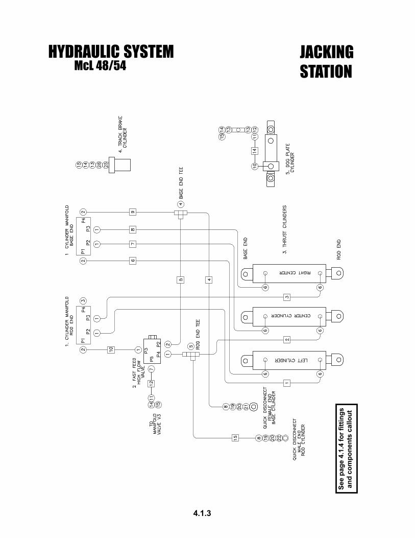
4.1.3
JACKINGSTATION
See
page
4.1
.4 fo
r fitt
ings
and
com
pone
nts
callo
ut

HYDRAULIC SYSTEMMcL 48/54
4.1.4
NOTE: For replacement Hose Assemblies,please include hose length and end fittings.
JACKINGSTATION
FITT
ING
DES
CR
IPTI
ON
PAR
T N
O.
1U
NIO
N 1
6MB-
16M
FT4
0054
52
ELB
OW
90
16M
B-1
6MF
T401
635
3PL
UG
16M
BT4
0512
04
TEE
16M
F-16
MF-
16M
FT4
0222
55
TEE
16FF
-16M
F-16
MF
T402
228
6E
LBO
W 9
0 20
MB
-16M
FT4
0171
07
ELB
OW
90
6MB
-6M
JT4
0125
08
BULK
HEA
D 9
0 16
MF-
16M
FT4
0039
59
UN
ION
16M
P-16
MF
T400
546
10SW
IVEL
90
4MP-
6MJ
T401
700
11U
NIO
N 6
MJ-
6MP
T400
028
12EL
BOW
, 90
6FP-
6MP
T401
065
13U
NIO
N 6
MP-
6MP
T400
803
14Q
UIC
K D
ISC
, MAL
E 6F
PT4
1200
815
CAP
QU
ICK
DIS
CT4
1201
016
UN
ION
4M
P-4M
JT4
0002
017
UN
ION
4FP
-6M
PT4
0002
318
UN
ION
4FP
-4FJ
T400
081
19U
NIO
N 1
6FF-
16M
JT4
0081
220
UN
ION
16F
J-16
MP
T400
815
21Q
UIC
K D
ISC
FEM
ALE
16FP
4800
776
22Q
UIC
K D
ISC
MAL
E 16
FP48
0077
523
QU
ICK
DIS
C F
EMAL
E 6F
PT4
1200
924
VEN
TED
CAP
4M
PT4
0080
125
UN
ION
16M
P-8F
PT4
0306
026
UN
ION
8M
P-6F
PT4
0002
4
HYD
RA
ULI
C C
OM
PON
ENTS
PAR
T N
O.
1C
YLIN
DER
MAN
IFO
LD (Q
TY 2
)48
0073
12
FAS
T FE
ED
VA
LVE
-FA
ST F
EED
CAR
TID
GE
4800
779
FAST
FEE
D B
OD
Y48
0078
03
THR
UST
CYL
IND
ER (Q
TY 3
)48
0072
94
TRAC
K BR
AKE
CYL
IND
ER
4
8107
505
DO
G P
LATE
CYL
IND
ER48
0171
0
#H
OSE
RO
UTI
NG
PAR
T N
O.
1
LE
FT C
YLI
ND
ER
, RO
D E
ND
-- R
OD
MA
NIF
OLD
P2
TH
4810
12
CEN
TER
CYL
IND
ER, R
OD
EN
D --
TEE
, RO
D E
ND
TH48
102
3R
IGH
T C
YLIN
DER
, RO
D E
ND
-- R
OD
MAN
IFO
LD P
3TH
4810
34
CYL
IND
ER B
ASE
TEE
-- Q
UIC
K D
ISC
FEM
ALE
TH48
104
5C
YLI
ND
ER
BA
SE
TE
E --
HIG
H F
LOW
VA
LVE
P2
TH48
105
6LE
FT C
YLIN
DER
, BAS
E EN
D --
BAS
E M
ANIF
OLD
P1
TH
4810
67
CEN
TER
CYL
IND
ER, B
ASE
END
-- B
ASE
MAN
IFO
LD P
2TH
4810
78
RIG
HT
CYL
IND
ER, B
ASE
END
-- B
ASE
MAN
IFO
LD P
3
T
H48
108
9C
YLIN
DER
BAS
E TE
E --
BASE
MAN
IFO
LD P
4TH
4810
910
RO
D M
AN
IFO
LD P
1 --
HIG
H F
LOW
VA
LVE
P3
TH48
110
11H
IGH
FLO
W V
ALV
E P
1 --
HY
D T
AN
K (J
AC
KIN
G S
TATI
ON
)TH
4811
112
HIG
H F
LOW
VA
LVE
P5
-- M
AN
IFO
LD V
3 (J
AC
KIN
G S
TATI
ON
)TH
4811
213
--
14D
OG
PLA
TE C
YLIN
DER
-- H
OU
SIN
G C
OU
PLIN
GTH
4811
4
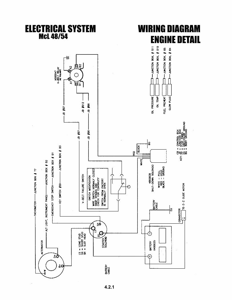
ELECTRICAL SYSTEMMcL 48/54
WIRING DIAGRAMENGINE DETAIL
4.2.1

ELECTRICAL SYSTEMMcL 48/54
WIRING DIAGRAMJUNCTION BOX DETAIL
4.2.2

WIRING DIAGRAMMcL 48/54
CONTROL BOX
4.2.3
HY
DR
AU
LIC
CLU
TCH
SO
LEN
OID
(N
O P
OLA
RIT
Y)

WIRING DIAGRAMMcL 48/54
INSTRUMENT PANEL
4.2.4

WIRING DIAGRAMMcL 48/54
COMPONENT WIRING
4.2.5
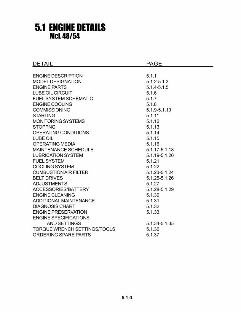
5.1 ENGINE DETAILS
DETAIL PAGE
ENGINE DESCRIPTION 5.1.1MODEL DESIGNATION 5.1.2-5.1.3ENGINE PARTS 5.1.4-5.1.5LUBE OIL CIRCUIT 5.1.6FUEL SYSTEM SCHEMATIC 5.1.7ENGINE COOLING 5.1.8COMMISSIONING 5.1.9-5.1.10STARTING 5.1.11MONITORING SYSTEMS 5.1.12STOPPNG 5.1.13OPERATING CONDITIONS 5.1.14LUBE OIL 5.1.15OPERATING MEDIA 5.1.16MAINTENANCE SCHEDULE 5.1.17-5.1.18LUBRICATION SYSTEM 5.1.19-5.1.20FUEL SYSTEM 5.1.21COOLING SYSTEM 5.1.22CUMBUSTION AIR FILTER 5.1.23-5.1.24BELT DRIVES 5.1.25-5.1.26ADJUSTMENTS 5.1.27ACCESSORIES/BATTERY 5.1.28-5.1.29ENGINE CLEANING 5.1.30ADDITIONAL MAINTENANCE 5.1.31DIAGNOSIS CHART 5.1.32ENGINE PRESERVATION 5.1.33ENGINE SPECIFICATIONS
AND SETTINGS 5.1.34-5.1.35TORQUE WRENCH SETTINGS/TOOLS 5.1.36ORDERING SPARE PARTS 5.1.37
McL 48/54
5.1.0

ENGINE DESCRIPTIONGENERAL 1
DEUTZ Diesel Engines
are the product of research anddevelopment ranging over manyyears. The know-how therebygained, coupled with highdemands with regard to quality,forms the guarantee for themanufacture of enginesfeaturing long service-life, highreliability, and low fuelconsumption.It goes without saying that thehigh demands regarding protec-tion of the environment are alsofulfilled.
Beware of Running Engine
Shut the engine down beforecarrying out maintenance orrepair work. Ensure that theengine cannot be accidentallystarted - accidents may otherwiseoccur. When the work iscomplete, be sure to refit anypanels and guards that have beenremoved.Never fill the fuel tanks while theengine is running. Observeindustrial safety regulations whenrunning the engine in an enclosedspace or underground.
Service and Maintenance
will also play a decisive role as towhether the engine fulfills to yoursatisfaction the demands youmake on it. Observance of theprescribed maintenance intervalsand careful carrying out of theservice and maintenance jobsare therefore essential.Particular attention must be givenwith regard to applicationsinvolving differing and harderoperating conditions ascompared with normaloperation.
Safety
When reading throughthis Manual, you will find
this symbol marking all safetyinstructions and proceed withspecial care. Pass on these safetyinstructions to your operatingpersonnel.In addition, it is also necessary toobserve the official safety andaccident prevention rules.
DEUTZ Service
In case of operational troubles andqueries concerning spare parts,please contact your DEUTZ agent.Where necessary, our trainedspecialists will ensure a quick andprofessional repair, using DEUTZspare parts. Genuine DEUTZspare parts are alwaysmanufactured to the latesttechnical standards.More information on DEUTZSERVICE can be found at the end ofthis Operation Manual.
Asbestos
The seals and gaskets used in this engine areasbestos-free. When carrying outmaintenance and repair work,please use appropriate spareparts.
5.1.1

MODEL DESIGNATION2.1 Model
2.1.1 Rating PlateThe model designation A, the engine serial number B andthe performance data are stamped on the rating plate. Themodel and engine serial number must be given when orderingparts.
2.1.2 Location of Rating PlateThe rating plate C is attached to the crankcase; dependingon the design, a second rating plate may be attached to theair duct.
2.1.3 Engine Serial NumberThe engine serial number D is stamped onto the crankcase aswell as on the rating plate.
2.1.4 Numbering of CylindersThe cylinders are numbered consecutively, beginning at theflywheel end.
Adjustments to the regulator are to be carried out only byauthorized DEUTZ SERVICE - specialists.
5.1.2

ENGINE DESCRIPTION2.1 Model
2.1.5 Direct Injection FL 912Engines with direct injection are used where high performance isrequired.
2.1.6 Two-stage Combustion FL 912WEngines with two-stage combustion are used where it is particu-larly important to keep exhaust emissions to an absoluteminimum.
5.1.3

ENGINE DESCRIPTION2.2 Engine Illustrations
2.2.1 Service Side F4L 912 1 Fan 2 V-belt (fan) 3 Injection pump 4 V-belt (alternator) 5 V-belt pully 6 Tension roller 7 Oil fill point 8 Oil pan 9 Oil drain plug10 Fuel pump11 Oil dipstick12 Lube oil filter13 Easy-change fuel filter14 Air duct cover15 Cylinder-head cover
2.2.2 Exhaust Side F4L 91216 Air intake pipe17 Exhaust manifold pipe18 Screen19 Alternator20 Starter21 Engine mounting22 Crankcase23 Crankcase ventilation
5.1.4
ENGINE DESCRIPTION2.2 Engine Illustrations
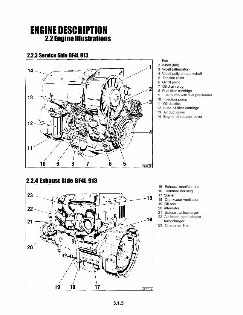
15 Exhaust manifold line16 Terminal housing17 Starter18 Crankcase ventilation19 Oil pan20 Alternator21 Exhaust turbocharger22 Air-intake pipe-exhaust turbocharger23 Charge-air line
2.2.4 Exhaust Side BF4L 913
1 Fan 2 V-belt (fan) 3 V-belt (alternator) 4 V-belt pully on crankshaft 5 Tension roller 6 Oil fill point 7 Oil drain plug 8 Fuel filter cartridge 9 Fuel pump with fuel precleaner10 Injection pump11 Oil dipstick12 Lube oil filter cartridge13 Air duct cover14 Engine oil radiator cover
2.2.3 Service Side BF4L 913
5.1.5

ENGINE DESCRIPTION2.3 Lube Oil Circuit
2.3.1 Lube Oil Circuit FL 912/913
2.3.2 Lube Oil Circuit BF6L 913
1 Oil Pan 2 Intake Manifold 3 Oil pump 4 Oil pressure control valve 5 Pressure-oil line 6 Bypass line or selectively 7 Finned pipe spiral or selectively 8 Frame oil cooler 9 Lube oil filter10 Safety valve11 Main oil gallery12 Crankshaft bearing13 Con-rod bearing14 Camshaft bearing15 Tappets16 Push rod (hollow, for oil feed to rocker arm lubrication)17 Rocker arm bearing18 Metering plug (r arm lubrication)*19 Protective sleeve for push rod20 Throttle bore (for lubrication of the gear wheels)21 Injection jet for cooling the pistons22 Connection for oil pressure gauge23 Oil pressure gauge24 Injection pump connected to lube oil circuit25 Connection point for oil heating**
1 Oil Pan 2 Intake manifold 3 Oil pump 4 Oil pressure control valve 5 Pressure-oil line 6 Connecting line to oil cooler 7 Frame oil cooler 8 Lube oil filter 9 Safety valve10 Main oil gallery11 Crankshaft bearing12 Con-rod bearing13 Camshaft bearing14 Tappets (with impulse lubrication of the rocker arm)15 Push rod (hollow, for oil feed to r. arm lubrication)16 Rocker arm bearing17 Metering plug (r arm lubrication)*18 Protective sleeve for push rod (oil return form cylinder head to crankcase)19 Throttle bore (for lubrication of the gear wheels)20 Injection jet for cooling the pistons21 Oil line for lub. of the exhaust turbocharger22 Oil ret. line from exhaust turboc. to the crankcase23 Oil pressure gauge24 Partial flow lube oil filter25 Connection point for oil heating**26 Injection pump connected to lube oil circuit
* only for inclined engines** in this instance the filter holder must be replaced. Please contact our service representative for this alteration.
5.1.6

ENGINE DESCRIPTION2.4 Fuel System Schematic
1 Fuel Tank 2 Fuel line from tank to fuel pump 3 Fuel supply pump 4 Easy-change fuel filter 5 Injection pump 6 Injection lines 7 Injection valves 8 Oil leakage line 9 Fuel overflow valve10 Overflow valve11 Fuel return line to tank A Clearance: keep as far apart as possible.
2.4.1 Fuel Circuit
5.1.7

2.5 Engine Cooling
1 Pressure-oil line from engine to exhaust thermostat 2 Air line to exhaust thermostat 3 Exhaust manifold pipe 4 Exhaust thermostat 5 Control line to hydraulic coupling 6 Hydraulic coupling 7 Cooling fan 8 Cooling fan drive 9 Oil return line to crankcase10 Ventilation line11 Adjusting pin with special seal
2.5.1 Regulation of Coolant Flow using the Exhaust Thermostat
2.5.2 Regulation of Coolant Flow using the Exhaust Thermostat and Solenoid
1 Pressure-oil line from engine to exhaust therostat 2 Air line to exhaust thermostat 3 Exhaust manifold pipe 4 Exhaust thermostat 5 Control line to hydraulic coupling 6 Hydraulic coupling 7 Cooling fan 8 Cooling fan drive 9 Oil return line to crankcase10 Ventilation line11 Adjusting pin with special gasket12 Solenoid
ENGINE OPERATION
5.1.8
ENGINE OPERATION3.1 Commissioning
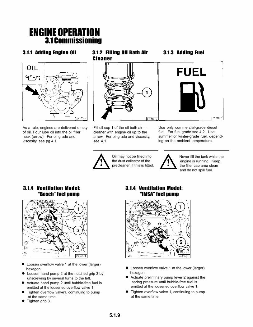
As a rule, engines are delivered emptyof oil. Pour lube oil into the oil fillerneck (arrow). For oil grade andviscosity, see pg 4.1
Fill oil cup 1 of the oil bath aircleaner with engine oil up to thearrow. For oil grade and viscosity,see 4.1
Use only commercial-grade dieselfuel. For fuel grade see 4.2. Usesummer or winter-grade fuel, depend-ing on the ambient temperature.
Oil may not be filled into the dust collector of the precleaner, if this is fitted.
Never fill the tank while the engine is running. Keep the filler cap area clean and do not spill fuel.
Loosen overflow valve 1 at the lower (larger) hexagon.
Loosen hand pump 2 at the notched grip 3 by unscrewing by several turns to the left.
Actuate hand pump 2 until bubble-free fuel is emitted at the loosened overflow valve 1.
Tighten overflow valve1, continuing to pump at the same time.
Tighten grip 3.
Loosen overflow valve 1 at the lower (larger) hexagon.
Actuate preliminary pump lever 2 against the spring pressure until bubble-free fuel is emitted at the loosened overflow valve 1.
3.1.1 Adding Engine Oil 3.1.2 Filling Oil Bath AirCleaner
3.1.3 Adding Fuel
3.1.4 Ventilation Model: “Bosch” fuel pump
3.1.4 Ventilation Model: “IMSA” fuel pump
Tighten overflow valve 1, continuing to pump at the same time.
5.1.9
ENGINE OPERATION3.1 Commissioning
3.1.5 Other Preparations
Check battery and cable connections see 6.7.1
Transport hooks Remove if fitted (see 6.7.3)
Trial run After the engine has been prepared, let it run for about 10 minutes without load.
During and after trial run - Check the engine for leaks.
After the engine has been turned off - Check the oil level, see 6.1.2 If necessary, top oil, see 3.1.1 Retension V-belts, see 6.5
Breaking in During the break-in phase - about 200 operating hours - check the oil level twice a day. After the engine is broken in, checking once a day will be sufficient.
3.1.6 Additional Maintenance Work
Change lube oil, see 6.1.2
Change oil filter cartridge, see 6.1.3
Change fuel filter cartridge, see 6.2.1
Check V-belts and retension as necessary, see 6.5
Check the engine for leaks.
Check the engine mount and adjust as necessary, see 9.2
Check valve clearance and adjust as necessary, see 6.6.1
The following maintenance should be carried outafter 50-150 operating hours:
3.1.7 Selector Switch for Oil Heater
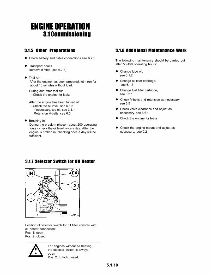
Position of selector switch for oil filter console withoil heater connection:Pos. 1: openPos. 2: closed
For engines without oil heating,the selector switch is alwaysopenPos. 2: to lock closed.
5.1.10

ENGINE OPERATION3.2 Starting
3.2.1 Electric Starting
with Cold-Start Aid/Flame Glowfr 60=9.5 and 19 volts
with Cold-Start/Flame Glow PlugFR 20/30 = 11 and 23 volts with heating pipe
Where possible, disengage the clutch to separate the engine from any driven parts.
Before starting, make sure that nobody is standing in the immediate vicinity of the engine or driven machine.After repair work:Check that all guards have beenreplaced and that all tools have beenremoved from the engine.When starting with flame glow system,do not use any other starter substance(e.g. injection with start pilot).Caution: If the speed regulator hasbeen removed, the engine must notbe tested under any circumstances:Disconnect the battery.
Starting without Cold-Start Aid
Move speed control lever 1 into idle position.
Insert key. - Position 0 = no operating voltage
Turn key clockwise - Position 1 = no operating voltage - Pilot lights come on.
Push the key in and turn it further clockwise against spring pressure - Position 2 = no function - Position 3 = start
Insert key. - Position 0 = no operating voltage
Turn key clockwise. - Position 1 = operating voltage - Pilot lights come on.
Push the key in and turn further clockwise against spring pressure - Glow plug indicator light comes on - Position 2 = Preheat for approx. 60 seconds (hold key in position)* - Glow plug indicator light goes out - Position 3 = start
Release key as soon as engine fires. - Pilot lights go out.
* By afterignition in position 2 for up to approx. 3 mins, it is possible to lower further the exhaust gas opacity in the revving-up phase.
Insert key. - Position 0 = no operating voltage
Push key in and turn further clockwise against spring pressure. - Position 2 = Preheat for approx. 60 seconds (hold key in position)* - Position 3 = Start
Turn key clockwise - Position 1 = operating voltage - Pilot lights comes on.
Insert key. - Position 0 = no operating voltage
Turn key clockwise - Position 1 = operating voltage - Pilot lights comes on.
Push the key in and turn further clockwise against spring pressure - Glow plug indicator light comes on - Position 2 = Preheat for approx. 20-30 seconds (hold key in posi-tion)* - Glow plug indicator light goes out
Release key as soon as engine fires. - Pilot lights go out.
* By afterignition in position 2 for up to approx. 3 mins, it is possible to lower further the exhaust gas opacity in the revving-up phase.
* By afterignition in position 2 for up to approx. 3 mins, it is possible to lower further the exhaust gas opacity in the revving-up phase.
Release key as soon as engine fires. - Pilot lights go out.
Do not actuate the starter for more than 20seconds. If the engine does not catch wait aminute then try again.If the engine does not catch after two attempts,refer to the Diagnosis Chart (see 7.1)
5.1.11

ENGINE OPERATION3.3 Monitering Systems
3.3.1 Engine Oil Pressure
Oil Pressure Pilot Light The oil pressure pilot light comes
on with operating voltage on and engine off.
The engine temperature gauge pointer should remain in the green sector most of the time. It should rarely enter the yellow-green sector. If the pointer enters the orange sector, the engine is overheating. Turn off and establish the cause from the Diagnosis Chart (see 7.1).
If the V-belt rips, pressure pin 1 of the electrical switch is actuated by the tension roller and an acoustic or light signal is given. Switch off the engine immediately to prevent overheating.
The oil pressure pilot light should go out when the engine is running.
The pointer must remain in the green sector over the entire range.
Oil Pressure IndicatorOil Pressure Gauge
The pointer must indicate the minimum oil pressure (see 9.1).
Temperature Gauge
3.3.2 Engine Temperature 3.3.3 Cooling Fan Drive
5.1.12

3.4 Stopping
Move speed control lever to low idle.
3.4.1 Mechanical Shutdown
3.4.2 Electrical Shutdown
Operate shutdown lever 2 until the engine comes to a stop. The charge pilot light and the oil pressure pilot light will come on when the engine stops.
Turn key counter-clockwise (to position 0) and remove. The pilot lights will go out.
Turn key counter-clockwise (to position 0) and remove. The pilot lights will go out.
Ignition Key
5.1.13
ENGINE OPERATION

ENGINE OPERATION3.5 Operating Conditions
3.5.1 Winter Operation
3.5.2 High Ambient Temperatures High Altitude
Lube Oil Viscosity - Select the oil viscosity (SAE grade) according to the ambient temperature when the engine is started, see 4.1.2 - Increase oil change frequency when operating below -10°C, see 6.1.1
Diesel Fuel - Use winter-grade diesel fuel for operation below 0°C, see 4.2.2
Additional Maintenance Work - Drain the sludge from the fuel tank once a week. (Unscrew the sludge drain plug). - If necessary, allow the oil in the oil bath air cleaner and the engine oil to settle at the ambient temperature. - Below -20°C, after removing the starter if necessary, smear the ring gear on the fly wheel via the pinion bore from time or time with cold-resistant grease, (e.g. Bosch grease FT 1 V 31).
Cold-Start Aid - At temperatures near or below freezing point, use glow plugs if necessary, see 3.2.1. This not only lowers the starting limit temperature, but provides easier starting at temperatures normally not requiring a starting aid.
Battery - Efficient cold starting requires a healthy battery, see 6.7.1 - The starting limit temperatures can be lowered by 4-5 °C by heating the battery up to about +20°C. (To do so, remove the battery and store in a warm place.)
As the altitude and ambient temperature rise, the density of air tends to decrease, which affects the maximum power output of the engine, the exhaust gas quality and, in extreme cases, the starting behavior. Under transient conditions, the engine can be used at altitudes up to 1000m and temperatures up to 30°C. If the engine is to operate under more severe conditions (at higher altitudes or temperatures), it will be necessary to reduce the injected fuel quality and thus, engine power.
If you have any doubts about engine operation under these or similar conditions, ask your engine or equipment supplierwhether the engine has been derated in the interests of reliability, service life and exhaust gas quality (smoke). Otherwise contact DEUTZ SERVICE.
5.1.14

OPERATING MEDIA4.1 Lube Oil
4.1.1 Quality Grade
4.1.2 Viscosity
Lube oils are differentiated according to theirperformance and quality class. In commom useare specifications named after the API (AmericanPetroleum Institute) and ACEA (European EngineOIl Sequences).
Approved API Oils:
At least: CF-4
Approved ACEA Oils:
At least E1-96
As the viscosity of the lube oil is dependent ontemperature, the choice of SAE grade should begoverned by the ambient temperature prevailing atthe engine operating site. Optimum operatingbehaviour will be attained if you take the accompa-nying oil viscosity diagram as a guide.Should the temperature fall temporarily below thelimits of SAE grade selected, cold starting may beaffected but the engine will not be damaged.In order to keep wear to a minimum, do not exceedapplication limits for extended periods of time.Oil changes dictated by the seasons can beavoided by using multi-grade lube oils. Multi-gradeoils - particularly light flowing oils - also reduce fuelconsumption.
Oil change intervals, see 6.1.1Oil capacities, see 9.1
5.1.15

OPERATING MEDIA4.2 Fuel
DIN EN 590
Use commercially available diesel fuel with lessthan 0.5% sulphur content. If the sulphur content ishigher than 0.5% oil change intervals should bereduced, see 6.1.1
The following fuel specifications / standards areapproved:
4.2.1 Quality Grade
4.2.2 Winter-Grade Fuel
BS 2869: A1 and A2 (with A2, take note of the sulphur content!)
ASTM D 975-88; 1-D and 2-D
NATO Code F-54 and F-75
Any exhaust emission levels, which may have beendetermined during type approval tests always referto the reference fuel prescribed by the authoritiesfor the type approval test.
Waxing may occure at low temperatures, cloggingthe fuel system and reducing engine efficiency. Ifthe ambient temperature is less than 0°C, winter-grade fuel (suitable down to -15°C) should be used.(This fuel is usually available from the fillingstations well in advance of the cold months). Dieselfuel containing additives (Super diesel) is often onsale as well, for use down to -20°C.
If summer-grade diesel fuel must be used attemperatures below 0°C, up to 60% kerosene canbe added (see diagram).
In most cases, adequate resistance to cold can beobtained by adding a flow improver (additive).Please inquire at DEUTZ-PARTNER.
Below -20°C, petroleum must be added. For the required mixing ratios please refer to the adjacent diagram.
For artic climate zones down to -44°C special diesel fuels can be used.
Mix in tank only. Fill with theappropriate amount of kerosenefirst, then add the diesel fuel.
5.1.16

ROUTINE MAINTENANCE5.1 Maintenance Schedule
5.2 Maintenance ChartsThe maintenance charts shown here aresupplied as self-adhesive labels with eachengine. They should be affixed where theycan be seen clearly on the engine or drivenequipment.
Check that this is the case.
If necessary, ask your engine or equipmentsupplier for a fresh supply of labels.Routine work should be carried outaccording to the schedule in 5.1
Stop the engine before carrying outany maintenance work.
5.1.17

ROUTINE MAINTENANCE5.3 Completed Maintenance Jobs
5.1.18

SERVICE AND MAINTENANCE6.1 Lubrication System
6.1.1 Oil Change Intervals The oil change intervals are
dependent on the engine application and the quality of the lube oil.
If the engine runs fewer hours during the year than stated in the table, the oil should be changed at least once a year.
The table refers to the following conditions: - For diesel fuel: sulphur content max. 0.5% by weight. - Continuous ambient temperatures down to -10°C (+14°F)
If the sulphur content is > 0.5 to 1% or the continuous ambient temperature below -10°C (+14°F), the intervals between oil changes should be halved.
In case of fuels containing more than 1% sulphur, contact your service representative.
6.1.2 Checking Oil/ Checking Engine Oil6.1.2.1 Checking Oil Level 6.1.2.2 Engine Oil Change
Change the oil with the engine off but stillwarm (lube oil temperature approx. 80°C)
Ensure that the engine or vehicle is in a horizontal position.
Ensure that the engine or vehicle is on a level surface.
Check the oil level, and if necessary, top up to the “MAX” mark. - If the oil level is only just above the “MIN” mark, more oil must be added.
Wipe the dipstick with a non-fibrous, clean cloth.
Remove the oil dipstick.
- Cold Engine: Check oil level. To this end:
- Warm Engine: Switch off engine, wait 5 minutes and check the oil level.
Insert it to the top and remove again.
The oil level must not fall below the “MIN”marking.
Allow the engine to warm up - Lube oil temperature approx. 80°C.
Switch off the engine.
Place oil tray under the engine. Unscrew drain plug.
Fit oil drain plug, with the new gasket and tighten firmly (for torque, see 9.2)
Fill with lube oil. - For grade/viscosity, see 4.1 - For quantity, see 9.1
Drain oil.
Check oil level, see 6.1.2.1
Be careful when draining hot oil -danger of scalds! Do not let usedoil run into the soil but catch it ina container ready for properdisposal.
5.1.19

SERVICE AND MAINTENANCE6.1 Lubrication System
6.1.3 Changing Oil Filter
6.1.4 Changing the Partail - Flow Oil Filter Insert
Undo the filter cartridge using a commercial tool and spin off.
Catch any dripping oil.
Clean any dirt from the filter carrier rim.
Tighten the oil filter cartridge with another half-turn.
Screw in the new cartridge finger tight against the gasket.
Lightly oil the rubber gasket of the new oil filter cartridge. Check oil pressure, see 3.3.1
Check oil level, see 6.1.2
Check cartridge seal for leaks.
Check and if necessary replace cover seal 4.
Fit new filter insert.
Unscrew oil drain plug 1 and drain off oil.
Unscrew tension screw 2. Remove the cover.
Screw in oil drain plug 1 with new seal
Unscrew the dirtied filter insert 3. Clean the filter housing.
Check for leaks and check the oil pressure during a test run.
Screw on cover and sealing ring 6.
Beware of burns from hot oil.
5.1.20

SERVICE AND MAINTENANCE6.2 Fuel System
6.2.1 Changing Fuel Filter
6.2.2 Fuel Precleaner Cleaning the Fuel “Bosch” model
Catch any fuel.
Tighten the fuel filter cartridge with a final half-turn. Undo fuel filter cartridge with
commercial tool and spin off.
Screw in the new cartridge finger tight against the gasket.
Apply light film of oil or diesel fuel to the rubber gasket of the new fuel filter cartridge.
Clean any dirt from the filter cartridge with a final half-turn.
Check for leaks.
Open fuel stopcock.
Close fuel stopcock.
No naked flames when workingon the fuel system.NO SMOKING!
Close the fuel shut-off valve. Loosen tensioning nut 2. Swing wire cup 1 to the side. Remove filter cone 5 with strainer 4
and clean in fuel.
Bleed the fuel system, see 3.1.4 Check for leaks.
Use a new seal 3 for filter cone 5.
Cleaning the Fuel Filter“IMSA” model
Refit in the reverse order. Bleed fuel system, see 3.1.4
Clean the fuel strainer 4 in fuel. Replace if necessary.
Check for leaks.
No naked flames when workingon the fuel system.NO SMOKING! 5.1.21
Remove cover 3.
Loosen hexagonal nut 1 and unscrew with sealing ring 2.Close the fuel shut-off valve.
Remove fuel strainer 4.
Close the fuel shut-off valve.

SERVICE AND MAINTENANCE6.3 Cooling System
6.3.1 Cleaning Intervals The amount of contamination in the
cooling system depends on the engine
Spilled oil or fuel on the engine increases the risk of contamination. Be especially careful if the engine is used in dusty environments.
Because applications vary, cleaning intervals have to be determined from case to case. The cleaning intervals given in the table on the right can be used as a guide.
Serious contamination can occur, for example: - on construction sites where there is a high level or air borne dust. - in harvesting applications where here are high concentrations of chaff and chopped straw in the vicinity of the machine.
5.1.22

The amount of dirt in the air cleaner depends on the amount of dust in the air and the size of the air cleaner used. If a high level of dust is anticipated, a cyclone-type precleaner can be fitted to the air cleaner.
Cleaning intervals will have to be determined from case to case.
If dry-type air cleaners are used, they should be cleaned only in accordance with the service indicator or the service switch.
After carrying out service work, reset the signal by pressing the button on the service indicator.
Air cleaner servicing is needed when: - Service indicator the red signal 1 is fully visible when the engine is off. - Service switch the yellow pilot light comes on when the engine is running.
SERVICE AND MAINTENANCE6.4 Combustion Air Filter
Release snap clips 2 and remove oil cup 3 together with filter element 4. If necessary pry element out with a screwdriver, taking care not to damage the rubber gasket 5.
Remove dirty oil and sludge. Clean oil cup.
Clean filter element 4 in diesel fuel and allow to drip-dry.
Inspect and replace rubber gasket 5 and 6 if necessary.
Clean filter housing 1 if very dirty. Undo wing nut 1 and remove cover 2.
Reposition collector bowl 3 onto lower section 4, fasten cover 2 in place by tightening wing nut 1.
Turn engine off and wait about 10 minutes for the oil to drain from filter housing 1.
Remove collector bowl 3 from lower section 4 and empty. Clean leaves, straw and other foreign matter from lower section of precleaner.
Refit oil cup and element to filter housing and secure with snap rings.
Fill oil cup with engine oil up to the mark (arrow) (for viscosity, see 4.1.2).
6.4.1 Cleaning Intervals
6.4.2 Emptying Cyclone Type Precleaner 6.4.3 Cleaning Oil Bath Air Cleaner
Never clean air cleaner withgasoline. Dispose of cold oil inaccordance with environmentalregulations.
Never fill collector bowl with oil. Replacecollector bowl if damaged.
5.1.23

SERVICE AND MAINTENANCE6.4 Combustion Air Filter
Undo clip fasteners 1.
Take off hood 2 and remove cartridge 3.
Clean cartridge 3. Blow out from inside out with dry compressed air (max. 5 bar), (or in difficult cases, tap out, taking care not to damage the cartridge, or wash according to manufacturer’s instructions.
The amount of dirt in the air cleaner depends on the amount of dust in the air and the size of the air cleaner used. If a high level of dust is anticipated, a cyclone-type precleaner can be fitted to the air cleaner.
Cleaning intervals will have to be determined from case to case.
Through regular removal and replacement, the gaskets on the filter cartridge can become damaged. Check paper filter (light showing through) and gaskets for damage. Replace if necessary.
After five cleaner services or after two years at the latest, replace safety cartridge 4 (never clean). To do so: - Undo hex. nut 5 and remove cartridge 4. - Install new cartridge, insert and tighten hex. nut.
Install cartridge 3, replace hood 2 and do up clip fasteners 1.
Empty dust discharge valve 1 by pressing apart lips of discharge slot as indicated by arrows.
Clean discharge slot from time to time.
Remove any caked dirt by pressing together the upper section of the valve.
6.4.4 Dry Type Air CleanerDust Discharge Valve Filter Cartridges
Clean cartridge (replace at least once a year).
Never clean filter cartridge withgasoline or hot fluids.
5.1.24

SERVICE AND MAINTENANCE6.5 Belt Drives
- Carefully remove the gauge without altering the position of the indicator arm 1. Read off the value where the black indicator arm 1 intersects scale 5 (arrow). For settings, see 9.1
- If necessary, retension belt and measure again.
To replace, press tension roller 1 using a commercial tool and remove the V-belts.
Loosen bolts 1, 2 and 3.
To check the tension of the V-belt, use a tension gauge (see 9.3). - Place indicator arm 1 into gauge. - Position gauge on V-belt 2, midway between the pulleys, with flange 3 on bottom of gauge against the edge of belt. - Push slowly on the black pad 4 at right angles to belt 2 until the spring is heard or felt to trigger.
Press alternator 4 outwards in direction of arrow A until correct belt tension is achieved.
Inspect entire V-belt for damage. Replace damaged V-belts. After installing new belts, run engine for
15 minutes, then check belt tension.
6.5.1 Checking V-Belts 6.5.2 Changing the Fan V-Belt
6.5.4 Changing Alternator Belts
Fit new V-belts.
Swing alternator 4 outwards in direction of arrow A until correct belt tension is achieved.
Remove V-belts and place on new belt.
Fit fan V-belts.
Loosen bolts 1, 2 and 3.
If the V-belt rips, pressure pin 1 of the electrical switch is actuated by the tension roller and an accoustic or light signal is given.
Functional check by pressing in pin 1.
Swing alternator 4 inwards in direction of arrow B.
Remove fan V-belts as decribed under 6.5.2
Retighten bolts 1, 2 and 3.
6.5.3 Tensioning Alternator Belts
Retighten bolts 1, 2 and 3.
6.5.5 Checking Warning System
Check tension and change beltsonly with the engine off. Refitbelt guard, if provided.
When new V-belts are fitted check thebelt tension after ca. 15 minutesrunning time.
Only check/tension/replace V-beltswhen the engine is at standstill. Ifnecessary, replace V-belt cover.
Retighten new V-belts after 15 minutesrunning time.
Only carry out a check when theengine is at a standstill.
5.1.25

If necessary replace the V-belts.
SERVICE AND MAINTENANCE6.5 Belt Drives
To tighten, remove one or more of the inner intermediate discs 3. Place the removed half of the V-belt pulley 2.
Retighten bolt 1. While tightening, simultaneously rotate the engine to prevent the V-belt from being crushed.
6.5.6 Tensioning and Changing Air Compressor V-Belts
6.5.7 Air Compressor Design with Doube V-Belt
Unscrew hexagonal bolts 1. Remove outer half of belt pulley 2.
Screw off hexagonal nut 1, remove V-belt pulley half 2, V-belt 3 and intermediate disc packet 7.
Remove intermediate disc 4, rear V-belt 3, intermediate disc packet 6 and V-belt disc half 5.
Fit in the reverse order. While tightening nut 1, the engine must be rotated to prevent the V-belts from being crushed.
To tighten, remove on or more of the intermediate discs from packet 6 or 7. Place the removed discs in front of or behind V-belt pulley halves 2, so that the V-belt remains aligned. Always take the same number of discs from each packet.
When new V-belts are fitted,check the belt tension after ca. 15minutes running time.
If a V-belt is worn or damaged, both belts in the setmust be replaced. The difference in the length of thenew V-belts may not exceed 0.15%.
Only check or replace V-belts when the engine is ata standstill. If necessary replace V-belt cover.When new V-belts are fitted, check the belt tensionafter approx. 15 minutes running time.
5.1.26

Adjust valve clearance if necessary: - Release locknut 4. - Use screwdriver 7 to turn setscrew 5 so that the correct clearance is attained after locknut 4 has been tightened.
Check valve clearance 1 between rocker arm / tappet contact face 2 and valve stem 3 with feeler gauge 6 (there should be only slight resistance when feeler blade is inserted). For permissible valve clearance, see 9.1
Remove the cylinder head cover.
Before adjusting valve clearance, allow engine to cool down for at least 30 minutes. The oil temperature should be below 80°C.
Position crankshaft as per schematic
6.6.1 Checking / Adjusting Valve Clearances
6.6.1.1 Valve Clearance Adjustments Schematic
Check and adjust valve clearance on all remaining cylinders.
Only inclined engines are fitted with an additional oil jetfor lubrication of the bearing. Any adjustments mustbe carried out in an authorized specialist workshop.
SERVICE AND MAINTENANCE6.6 Adjustments
Replace cylinder head cover (use new gasket if needed).
Crankshaft Position 1: Turn crankshaft until both valves in cylinder 1 overlap (exhaust valve about to close, inlet valve about to open). Adjust clearance of valve marked in black on schematic. Mark respective rocker arm with chalk to show that adjustment has been done.
Crankshaft Position 2: Turn crankshaft one full revolution (360°). Adjust clearance of valves marked in black on schematic.
5.1.27
6.7.1 Battery6.7.1.1 Checking Battery and Cable Connectors
SERVICE AND MAINTENANCE6.7 Accessories
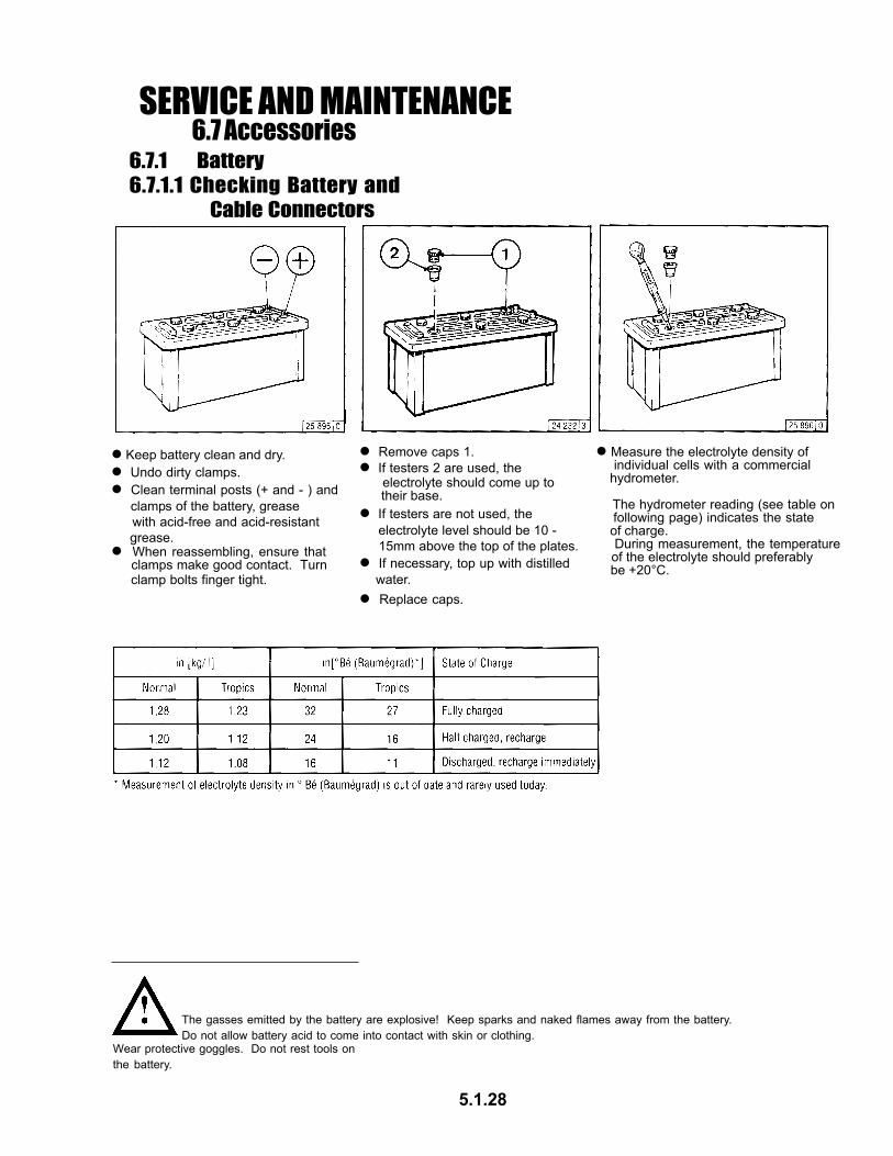
Remove caps 1.
If testers are not used, the electrolyte level should be 10 - 15mm above the top of the plates.
If testers 2 are used, the electrolyte should come up to their base.
If necessary, top up with distilled water.
Replace caps.
Measure the electrolyte density of individual cells with a commercial hydrometer.
The hydrometer reading (see table on following page) indicates the state of charge. During measurement, the temperature of the electrolyte should preferably be +20°C.
The gasses emitted by the battery are explosive! Keep sparks and naked flames away from the battery.Do not allow battery acid to come into contact with skin or clothing.
Wear protective goggles. Do not rest tools onthe battery.
5.1.28
Keep battery clean and dry. Undo dirty clamps. Clean terminal posts (+ and - ) and
clamps of the battery, grease with acid-free and acid-resistant grease.
When reassembling, ensure that clamps make good contact. Turn clamp bolts finger tight.

Never disconnect the cable between battery, alternator and regulator while the engine is running.
Be sure not to confuse the battery terminals.
If, however, it is necessary to start and operate the engine without the battery, disconnect the regulator from the alternator before starting.
After transportation and before commissioning of the engine: Remove transport eyes 2. In case of electric welding connect
ground terminal on the welder directly to the piece being welded.
Always use proper lifting tackle 1 when transporting the engine.
Replace defective bulb of the charge pilot lamp immediately.
The habit of touching a lead against the frame to check whether it is live must under no circumstances be used with three-phase electrical systems.
When washing the engine, cover up the alternator and regulator.
Use only the correct lifting tackle.
6.7.2 Three-Phase Alternator
6.7 AccessoriesSERVICE AND MAINTENANCE
6.7.3 Lifting Tackle
5.1.29

6.8 Engine CleaningSERVICE AND MAINTENANCE
6.8.1 Cleaning the Engine
Switch off the engine. Remove engine covers, cooling air
hoods. Replace following cleaning and before test run.
Cover electrical / electronic components / connections (e.g. alternator, starter, regulator, solenoid).
Pass compressed air through the engine, being careful with the cooler and cooling fins (start at the exhaust side). Remove dirt which has been blown into the inner compartment.
Spray engine with commercial cold-cleaning compound and leave to work for approx. 10 minutes.
Drive the engine warm so that remaining water evaporates.
Drive the engine warm so that remaining water evaporates. Spray engine clean with water jet
and if necessary repeat procedure.
Clean engine with steam jet (max. spray pressure 60 bar, max. steam temperature 90°C).
With Compressed AirWith Cold-CleaningCompound
With High=PressureEquipment
Switch off the engine. Remove engine covers, cooling-air
hoods. Cover electrical / electronic
components / connections (e.g. alternator, starter, regulator, solenoid).
Switch off the engine. Remove engine covers, cooling-air
hoods. Cover electrical / electronic
components / connections (e.g. alternator, starter, regulator, solenoid).
The engine may only be cleanedwhen it is at a standstill.
5.1.30

6.9 Additional MaintenanceSERVICE AND MAINTENANCE
6.9.1 Checking the Mountings
Cylinder head cover 1 When functioning correctly, the heating pipe heats up via the integrated heating coil when starting the preheating - heating pipe - air intake pipe
Air-intake pipe 2
Move speed adjustment lever and shut-off lever to “stop” position.
Press in key and turn further clockwise against the spring pressure. - Position 2 = preheat, hold for approx. 1 minute. - Preheat lamp lights up.
Exhaust line 3 Coupling sleeves
Rotate engine with starter, key on switch position 3.
Engine mounting 4
6.9.2 Checking the Function of the Heating Pipe
6.9.3 Checking the Function of the Flame Glowing System
When functioning correctly, intake pipe 4 heats up in the vicinity of flame glow plug 2 when starting with preheating.
Loosen pipe connection 1.
Fuel must be emitted at loosened pipe connection. Otherwise have the system, solenoid 3, checked by a specialist.
Turn key clockwise. - Postion 1 = operating voltage - Pilot light comes on.
Insert key - Position 0 = no operating voltage
Remove flame glow plug 2. Loosen pipe connection 1.
Rotate engine with starter, key in switch postition 3.
Fuel must be emitted at flame glow plug 2, replace plug 2 as necessary.
Refit flame glow plug 2 on fuel line. Keep clear of rotating parts.
Use sealant DEUTZ DW 47 when fitting flame glow plug 2.
Test Stage 1: Test Stage 2: Test Stage 3:
Collect any leaked fuel anddispose of in an environmentallyfriendly fashion. Otherwise flame glow plug
defective or power interrupted.
5.1.31

7.1 Diagnosis ChartFAULTS, CAUSES AND REMEDIES
5.1.32

Drain fuel from tank.
If the engine is to remain idle for an extended period of time, itis necessary to take protective measures to prevent rustformation. The preservative measures described here willprotect the engine for up to 6 months. The procedure will haveto be reversed before the engine is recommissioned.
Recommended cleansing agent to remove preservatives when recommissioning engine: - Petroleum benzine (hazardous materials class A3)
Anti-corrosion oils to specification: - MIL-L-21260B - TL 9150-037/2 - Nato Code C 640 / 642
If necessary, clean oil bath cleaner, see 6.4.3, and fill with anti-corrosion oil.
Run engine until warm, then turn off.
Drain engine oil, see 6.1.2 and fill with anti-corrosion oil.
Clean engine (with cold cleansing agent if preferred) using high pressure equipment.
Make up a mixture of 90% diesel fuel and 10% anti-corrosionoil, and refill fuel tank.
8.1.1 Preserving Engine
8.1ENGINE PRESERVATION
8.1.2 Removing Engine Preservatives
Spray grooves on V-belts pulleys with anti-corrosion spray.
Turn engine off.
Turn engine over manually several times to preserve the cylinders and combustion chamber. When rotating with starter, place shut-off lever in stop position.
Run engine for about 10 minutes.
Remove plugs from intake port and exhaust port.
Remove V-belts and store dry in wrapped condition.
Install V-belts. Retension after brief operation if necessary, see 6.5
Set the engine in operation.
Remove anti-corrosion agent from grooves in V-belt pulleys.
5.1.33

9.1 Engine Specifications and SettingsTECHNICAL SPECIFICATIONS
5.1.34
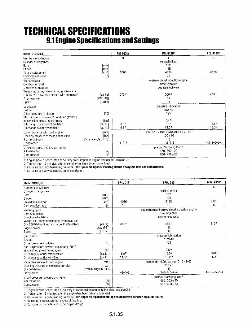
9.1 Engine Specifications and SettingsTECHNICAL SPECIFICATIONS
5.1.35

9.2 Torque Wrench SettingsTECHNICAL SPECIFICATIONS
9.3 Tools
The V-belt tension gauge can be obtainedunder order number 8115 from:
COMPANY WILBÄRPostfach 14 05 80D-42826 Remscheid
TECHNICAL SPECIFICATIONS
5.1.36

Order informationPlease specify the following informa-tion when ordering original DEUTZparts.
- Engine no.
- Ident. no.
- Quantity
Document structure- The picture diagrams in this spare parts list are sorted according to engine assembly groups.
- Each section is preceded by an overview of the assembly groups.
- The ident. no. 08/23 us made up of the assembly group (e.g. 08) and item number (e.g. 23).
ORDERING SPARE PARTS
5.1.37

ENGINE MAINTENANCE SCHEDULEMcL 48/54
DATE/HRS SERVICE PERFORMED BY
5.1.38

NOTESMcL 48/54
5.1.39

5.2 -5.8 MACHINE COMPONENTSMcL 48/54
5.2.0
DETAIL PAGE
GEARBOX 5.2.1-5.2.3TRANSMISSION PARTS 5.3.1-5.3.14HYDRAULIC PUMP COUPLING 5.4.1HYDRAULIC CLUTCH 5.5.1HYDRAULIC THRUST CYLINDER 5.6.1HYDRAULIC DOG PLATE CYLINDER 5.7.1HYDRAULIC VALVE 5.8.1

McL 48/54GEARBOX COMPONENTS
5.2.1

GEARBOX COMPONENTSMcL 48/54
����� ���� ���� � ��������
�� � ��������� ��� ��� � ��������� ����������������� � ��������� ����������������� � ��������� ��������� � �������� ��� �!��������"� � #�������� ��� �!��������$� � %�������� ��� �!��������&� � ��������� ��� �!���������� � '�������� ���&����(� � ��������� �����)�*�+� � ��������� ���� �,-������ � ��������� ����,.�� � ��������� "������/� � ��������� �+0,-������%� #� �������� �+0,-�������� � #�������� ����*�����0� � %�������� ���������� # ��������� ������������ � '�������� ������$� � ��������� �������1�*��� � ��������� �������&� � ��������� ��������������2� � ��������� �������������� � ��������� ����������� ���� � �������� ����������� � #�������� ����*!����� �"� # %�������� ��� �!���������� � ��������� �������-$,��������#� � '�������� ����*!�������� � � ��������� ����*!���*��3#� � ��������� �� ������� ��� � ��������� �������� � � ��������� �4��"�5����6� � ��������� !�+,"!������ ��!� � �������� !�+,"!������ ��% � #�������� �+,+��/����� ���� � %�������� �+,+��/����� ���� �� ��������� 7��(���*��3# � '�������� ���8�������
� � ��������� ����*!���*��3
# � ��������� �� �����4��
5.2.2
Note: McLaughlin Manufacturing Co. is not authorized to service Gearboxes.Consult McLaughlin Manufacturing Co. for repair manual or the name of anauthorized service dealer near you.
MODEL#
SERIAL #
GEARBOX MAINTENANCE SCHEDULEMcL 48/54
DATE/HRS SERVICE PERFORMED BY
5.2.3

TRANSMISSION COMPONENTSMcL 48/54
5.3.1
MODEL#
SERIAL #
Note: McLaughlin Manufacturing Co. is not authorized to service transmissions. Consultan authorized dealer of the transmission manufacturer for parts and /orservice. Transmission model and serial number is required for part orders.
Contact McLaughlin Manufacturing Co. for a distributer near you.

TRANSMISSION DETAILMcL 48/54
SHIFT BAR HOUSING
5.3.2
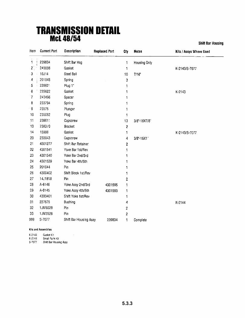
TRANSMISSION DETAILMcL 48/54
5.3.3

TRANSMISSION DETAILMcL 48/54
LEVER ASSEMBLY
5.3.4
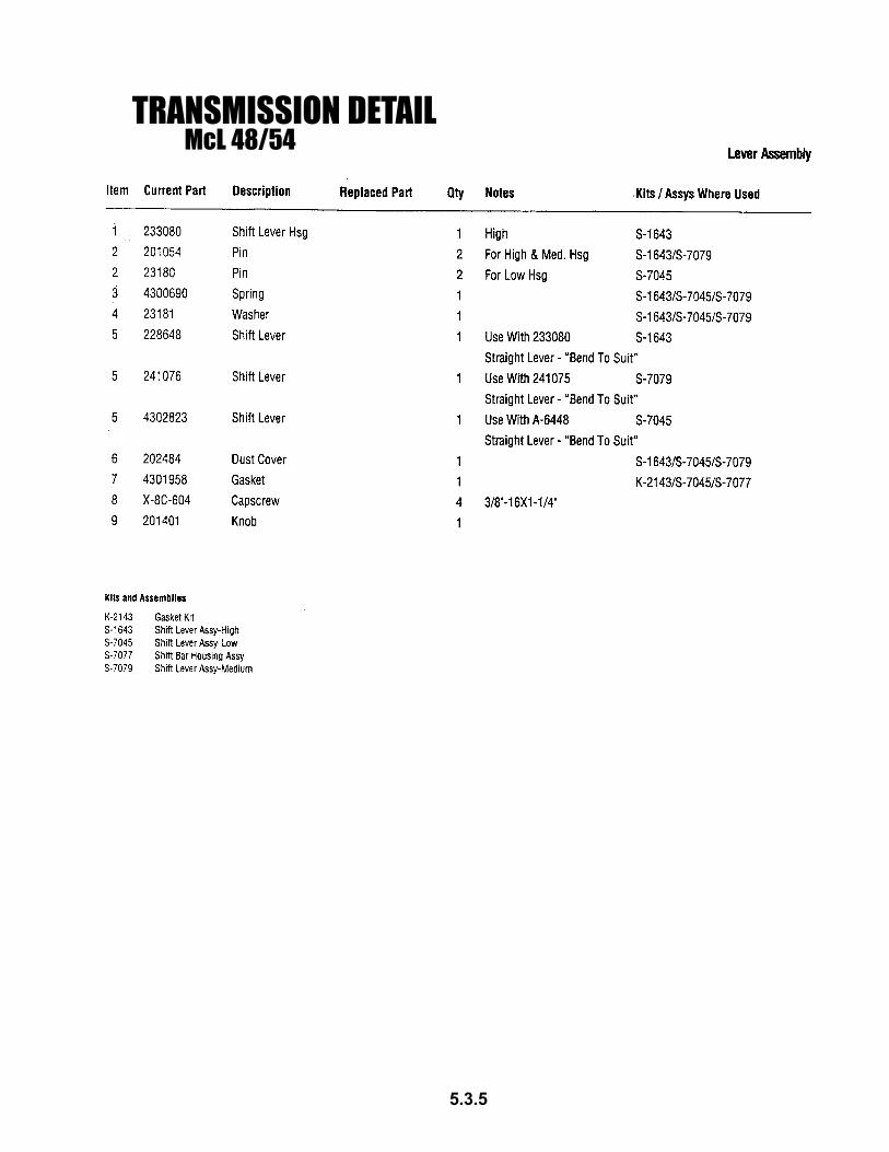
TRANSMISSION DETAILMcL 48/54
5.3.5

TRANSMISSION DETAIL
TRANSMISSION CASE
McL 48/54
5.3.6

TRANSMISSION DETAILMcL 48/54
5.3.7

TRANSMISSION DETAILMcL 48/54
TRANSMISSION CASE
5.3.8

TRANSMISSION DETAILMcL 48/54
5.3.9
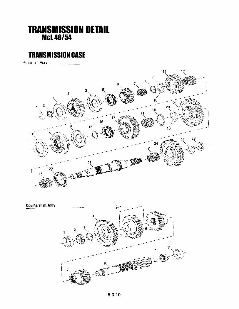
TRANSMISSION DETAIL
TRANSMISSION CASE
McL 48/54
5.3.10

TRANSMISSION DETAILMcL 48/54
5.3.11

TRANSMISSION DETAILMcL 48/54
INPUT SHAFT
5.3.12

TRANSMISSION DETAILMcL 48/54
5.3.13

TRANSMISSION MAINTENANCE SCHEDULEMcL 48/54
5.3.14
DATE/HRS SERVICE PERFORMED BY
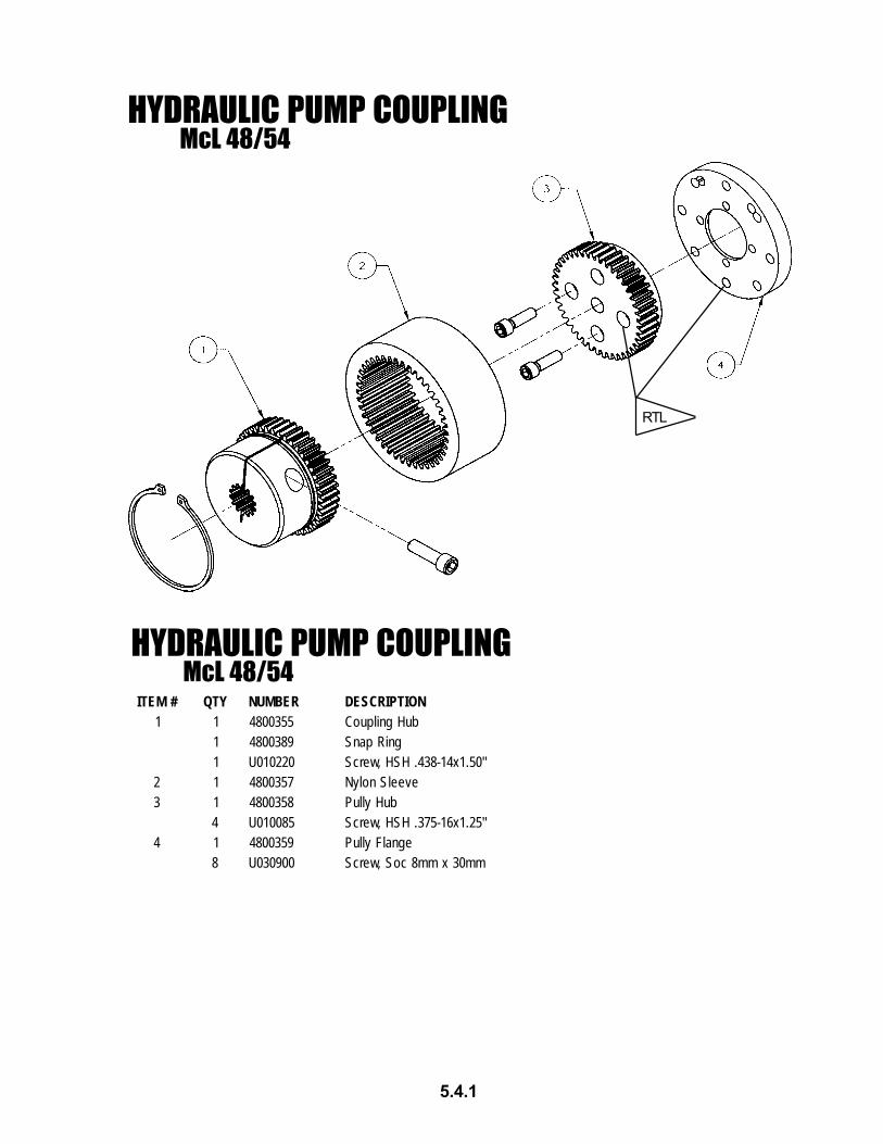
HYDRAULIC PUMP COUPLING
HYDRAULIC PUMP COUPLINGMcL 48/54
5.4.1
McL 48/54
RTL
#METI YTQ REBMUN NOITPIRCSED1 1 5530084 buHgnilpuoC
1 9830084 gniRpanS1 022010U "05.1x41-834.HSH,wercS
2 1 7530084 eveelSnolyN3 1 8530084 buHylluP
4 580010U "52.1x61-573.HSH,wercS4 1 9530084 egnalFylluP
8 009030U mm03xmm8coS,wercS

HYDRAULIC CLUTCH ASSEMBLYMcL 48/54
5.5.1
HYDRAULIC CLUTCH ASSEMBLYITEM# QTY NUMBER DESCRIPTION1 1 481039901 RETAINING RING2 1 481039902 ANGULAR CONTACT BEARING (7215)3 1 481039903 ANGULAR CONTACT BEARING (7217)4 1 481039904 CYLINDER ASSEMBLY5 1 481039905 PISTON6 1 481039906 SPACER7 1 481039907 BEARING HUB8 1 481039908 SEPARATOR PLATE9 6 481039909 HIGH COLLAR LOCK WASHER10 6 481039910 5/16-18 UNC X 0.75 LG SHCS11 2 481039911 FRICTION DISC12 6 481039912 COMPRESSION SPRING13 1 481039913 SPACER14 3 481039914 1/4-20 UNC X 0.50 LG FHSCS15 1 481039915 O-RING16 1 481039916 O-RING17 3 481039917 5/16-18 UNC X 0.625 LG FHSCS18 1 481039918 PRESSURE PLATE19 2 481039919 #10-24 X 0.75 LG SHCS20 1 481039920 HUB21 1 481039921 BACKPLATE

HYDRAULIC THRUST CYLINDER COMPONENTSMcL 48/54
HYDRAULIC CYLINDER
Complete Seal Kit to include:
McL 48/54
5.6.1
����� ���� ����� ���
� � ��������
� �������� � ������ � ������� � ����� �������
#METI .YTQ REBMUN NOITPIRCSED1 1 109270084 ylbmessAebuT2 1 209270084 ylbmessAdoR3 1 309270084 notsiP4 1 409270084 ylbmessAdnalGdoR5 1 509270084 tuNkcoL6 1 609270084 tiKlaeS
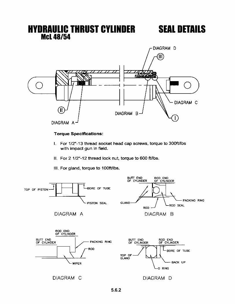
HYDRAULIC THRUST CYLINDER SEAL DETAILSMcL 48/54
5.6.2

HYDRAULIC DOG PLATE CYLINDERMcL 48/54
McL 48/54HYDRAULIC DOG PLATE CYLINDER SEAL KIT
ASSEMBLY
5.7.1
O-RING#218
O-RING#014
O-RING#131
O-RING#210
WIPER
New Seal Kit Reference Print
ITEM# QTY NUMBER DESCRIPTION1 1 4801710-05 Threaded Cap2 1 4801710-15 Rod/Clevis Weldment3 1 4801710-10 Barrel/Clevis Weldment4 1 4801710-20 Seal Kit

HYDRAULIC VALVE PARTSMcL 48/54
VALVE HANDLE - MAIN THRUST VALVE
5.8.1
McL 48/54
#METI .YTQ REBMUN NOITPIRCSED1 1 0180084 hctiwShtiwpirG2 1 3170163 retpadAreveLevlaV3 1 4580084 retpadAhctiwS

6.1 OPERATING
NOTE:1. Engaging the clutch against an immovable load, will cause premature failure of the clutch.Do not cycle the clutch (on/off/on/off etc.) with augers under-load.
COLD WEATHER OPERATION
Cold weather affects the operation of the boring machine. Cold hydraulic fluid causes sluggish machineperformance and can contribute to the premature failure of some machine components. Before starting tobore, the machine and hydraulic fluid must be at operating temperature (i.e. the machine must be warmed-up before boring).
Warm-up procedure:1. Start the machine and let it run at idle for 1-2 minutes.2. Slowly increase the engine rpm to about 1/2 to 3/4 full throttle3. Allow the engine to run at this higher speed for 4-5 minutes4. Extend and retract the thrust cylinders to warm up the hydraulic fluid.5. Occasionally running the machine over relief will help to reduce the warm-up time.
Only after the machine is warmed up should you begin to bore!
Hydraulic Clutch Operation:SLUGGISH OR DELAYED APPLY TIME FOR THE CLUTCH CAN CAUSE PREMATURE FAILURE.The apply time for the clutch (the time it takes to build full pressure) is critical to the operation of themachine. Normal clutch apply time is less than 2 seconds. If the apply time is greater than 2 seconds,wait until the oil temperature increases before boring. The apply time can be monitored by the pressuregauge on the console panel. Cycle the clutch during warm-up, waiting 10 seconds between engagements.WHEN APPLYING THE CLUTCH DURING THE WARM-UP PERIOD, THE TRANSMISSION MUST BE INNEUTRAL. Do not cycle the clutch during warm-up while coupled to loaded augers. Boring with anextended clutch apply time will cause premature failure of the clutch.
The hydraulic clutch operating system has 2 switches.1. O.P.C. Switch2. Clutch SwitchBoth the O.P.C. switch and the Clutch switch must be in the “ON” position
before the clutch will operate. If the clutch does not operate, make sure that both of theseswitchs are “ON”.The hydraulic pressure is set at the factory for 225 psi. This pressure must be maintained for properoperation. DO NOT operate the clutch if the clutch pressure gauge is reading below 150 psi. Too low anoperating pressure will result in premature clutch failure.
HYDRAULIC CLUTCHMcL 48/54
6.1.1

HYDRAULIC CLUTCHMcL 48/54
COLD WEATHER OPERATION
Hydraulic Fluid:Use the alternate hydraulic fluid for the following:
- To reduce warm-up time before boring.- When consistently boring in cold weather.
Standard hydraulic fluid:- ISO grade #46 with anti-wear additives.- 76 Unax AW #46- Or equivalent
Alternate hydraulic fluid:- ISO grade #32 Wide Temperature Range oil with anti-wear additives.- 76 Unax AW-WR #32- Or equivalent
Consult McLaughlin for more information.
6.1.2

HYDRAULIC CLUTCHMcL 48/54
6.2 TROUBLESHOOTING
DANGER: DO NOT OPERATE MACHINE IF CLUTCH IS NOT OPERATING PROPERLY. DEATH ORSERIOUS INJURY WILL RESULT.
The hydraulic clutch supplied with this machine is a dry-running, self-adjusting, twin-disk clutch. Theclutch requires very little maintenance. Following is a list of symptoms which may require servicing theclutch.
1. ContaminationThe clutch is designed to run in a dry environment. However, the clutch housing can become contami-nated. Contamination can result from dirt or sandy grit, oils, or water (which causes rust) entering theclutch housing.
Clean the disc pack kit with kerosene to restore to normal condition.
2. Drag in NeutralIt is natural for a twin-disc clutch to have a small amount of drag in the disengaged state. The drag shouldbe more noticeable at low engine speeds and in low transmission gears.
A. New machines or rebuilt clutchesThere is an indeterminate break-in time required for new clutches. Once a clutch has been working for awhile, it should seat itself and neutral drag should be at a minimum.
B. Abrupt changes in clutch dragIf the drag in the clutch abruptly increases, it may be due to insufficient spring tension between the clutchdiscs. Weaker springs cause more drag between the discs of the clutch. Excessive heat, generated inthe clutch by cycling the clutch or by applying the clutch against locked augers, will weaken the springsand cause excessive nuetral drag.
Replace disc pack kit and inspect all other components for damage and replace as necessary.
Refer to the Clutch Components and Disassembly/Assembly section of this manual for components andproper clutch service procedures.
6.2.1

PAGE LEFT BLANK

7.1.0
SERVICE AND REPAIR INSTRUCTIONSMcL-48/54
DETAIL PAGE
MACHINE SPLIT 7.1.1COUPLING (PUMP & GEARBOX) 7.2.1HYDRAULIC PUMP COUPLING 7.3.1DOG PLATE 7.4.1THRUST CYLINDER 7.5.1HYDRAULIC CLUTCH 7.6.1PUMP SETTINGS AND ADJUSTMENTS 7.7.1MAIN THRUST VALVE ADJUSTMENT 7.8.1

McL-48/54SERVICE AND REPAIR INSTRUCTIONS
DANGER:Crushing weight will cause serious injury.Place machine on solid surface to preventrollover or falling.
CAUTION:Do not modify this machine. Use only autho-rized McLaughlin repair parts. Failure tocomply may result in serious injury. Service
this equipment according with maintenance instructionsin this manual.
WARNING:Moving parts. Keep all guards in place.Shut down engine before service or
maintenance. Being caught in machinery couldcause serious injury.
CAUTION:High Pressure. Leaking hydraulic fluidunder pressure may penetrate and
cause serious injury. Check for leaks withcardboard. Relieve pressure before working onany system.
7.1 Machine Split Instructions
A. Removing the Carriage
Important Note: If the jacking station is to be re-moved from the track, then do the following, in se-quence, before removing, the carriage:
1.) Fully retract dog pins.2.) Close dog pin valve while pins are
retracted.3.) Turn OFF dog pin switch.4.) Fully retract thrust cylinders.
1.) With the engine OFF, and the key in the OFFposition, cycle the thrust valve handle up and down afew times to release any pressure in the system.Disconnect all hydraulic and electrical connections.There are a total of five hydraulic connections and oneelectrical connection. Use Figures 1 a-d to identifyconnection points.
• Main Thrust Valve - 2 hydraulic connec tions. (Figure 1a)• Track Brake - 1 hydraulic connection (Figure 1b)• Dog Plate - 1 hydraulic connection, 1 electrical connection. (Figure 1c)• Fast Feed Valve - 1 hydraulic connections (Figure 1d)
Install all caps on disconnects.
2.) There are eight bolted connection between thejacking station and carriage. Four bolts fasten verti-cally and four bolts fasten horizontally. Loosen androtate the carriage hold down bolts out of their carriageslots.. (Figure 2)
3.) Use the four lifting eyes on the roll bars to raise thecarriage out of the jacking station. DO NOT LIFT THECARRIAGE AT ANY OTHER POINT EXCEPT BY ALL
7.1.1
1a
1b
1c
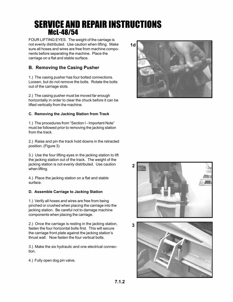
SERVICE AND REPAIR INSTRUCTIONSMcL-48/54
7.1.2
1d
2
3
FOUR LIFTING EYES. The weight of the carriage isnot evenly distributed. Use caution when lifting. Makesure all hoses and wires are free from machine compo-nents before separating the machine. Place thecarriage on a flat and stable surface.
B. Removing the Casing Pusher
1.) The casing pusher has four bolted connections.Loosen, but do not remove the bolts. Rotate the boltsout of the carriage slots.
2.) The casing pusher must be moved far enoughhorizontally in order to clear the chuck before it can belifted vertically from the machine.
C. Removing the Jacking Station from Track
1.) The procedures from “Section I - Important Note”must be followed prior to removing the jacking stationfrom the track.
2.) Raise and pin the track hold downs in the retractedposition. (Figure 3)
3.) Use the four lifting eyes in the jacking station to liftthe jacking station out of the track. The weight of thejacking station is not evenly distributed. Use cautionwhen lifting.
4.) Place the jacking station on a flat and stablesurface.
D. Assemble Carriage to Jacking Station
1.) Verify all hoses and wires are free from beingpinched or crushed when placing the carriage into thejacking station. Be careful not to damage machinecomponents when placing the carriage.
2.) Once the carriage is resting in the jacking station,fasten the four horizontal bolts first. This will securethe carriage front plate against the jacking station’sthrust wall. Now fasten the four vertical bolts.
3.) Make the six hydraulic and one electrical connec-tion.
4.) Fully open dog pin valve.
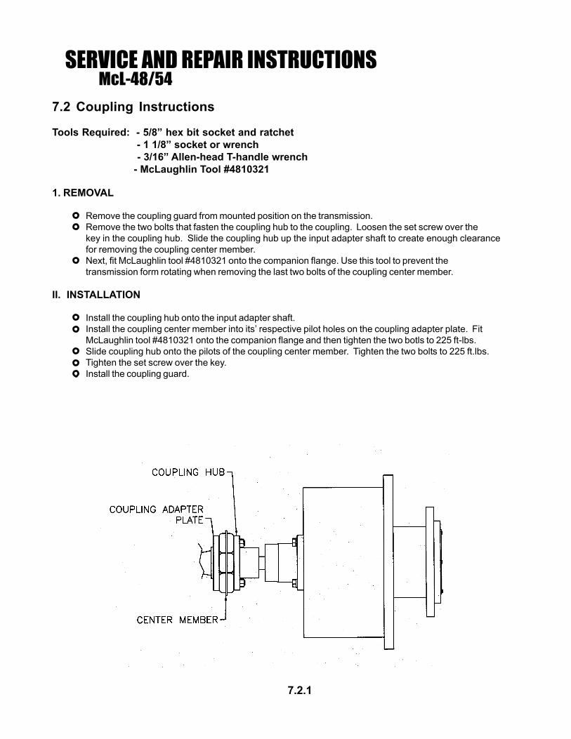
7.2 Coupling Instructions
Tools Required: - 5/8” hex bit socket and ratchet - 1 1/8” socket or wrench - 3/16” Allen-head T-handle wrench - McLaughlin Tool #4810321
1. REMOVAL
Remove the coupling guard from mounted position on the transmission.Remove the two bolts that fasten the coupling hub to the coupling. Loosen the set screw over thekey in the coupling hub. Slide the coupling hub up the input adapter shaft to create enough clearancefor removing the coupling center member.Next, fit McLaughlin tool #4810321 onto the companion flange. Use this tool to prevent thetransmission form rotating when removing the last two bolts of the coupling center member.
II. INSTALLATION
Install the coupling hub onto the input adapter shaft.Install the coupling center member into its’ respective pilot holes on the coupling adapter plate. FitMcLaughlin tool #4810321 onto the companion flange and then tighten the two botls to 225 ft-lbs.Slide coupling hub onto the pilots of the coupling center member. Tighten the two bolts to 225 ft.lbs.Tighten the set screw over the key.Install the coupling guard.
SERVICE AND REPAIR INSTRUCTIONSMcL-48/54
7.2.1

7.3.1
Pump Coupling
Nylon Sleeve
Adapter Plate
Assembly
A1. Pilot the adapter plate to the engine crankshaftpulley. Make sure that all hoses are properly linedup and that the adapter is sitting flush against thepulley. Apply Loctitie #271 to the screws andtighten the screws in an alternating circularpattern.
A2. Pilot the coupling hub into the adapter. Makesure that the coupling is sittling properly on theface of the adapter. Apply loctite #271 to thescrews andtighting the screws in an alternatingpattern.
A3. Install the nylon sleeve onto the coupling.
A4. Install the pump coupling onto the pump
SERVICE AND REPAIR INSTRUCTIONSMcL-48/54
7.3 Hydraulic Pump Coupling
Alignment
Loosen, but do not remove the 4 screws that attachthe pump adapter plate to the pump mount. Adjustthe pump plate until the nylon sleeve on the couplingslides freely. Tighten the 4 screws.(Fig. 1-c)
Disassembly/Assembly
D1. Remove the screw for the pump and pull thepump out of the adapter plate. Do not remove the 4screws which attach the adapter plate to the pumpmount.
D2. Loosen the coupling cross-clamp and remove thecoupling from the pump shaft.
D3. Remove the nylon sleeve.
D4. Remove the screws that attach the coupling hubto the adapter plate and remove the coupling hub.

7.4 DOG PLATE
Dog Pin Indicators - The dog pin indicator lights should come on when the dog pins are retracted and gooff when the dog pins are fully extended. Adjust the switches so the lights give an accurate indication ofthe dog pin position. Sometimes the dog pin may be in a bind and may not be able to extend fully. Checkthat the dog pins are working freely before making any adjustments. Make sure that the dog pin valve isopen enough (5-6 turns) for the pins to move freely.
Dog Pin Indicator Switch Adjustment
1. Extend the dog pins.
2. Remove the top plate on the dog plate cover box.
2. Turn the ignition switch to the “ON” position and note dog pin positions and dog pin indicator lights.
3. The switch brackets allow for adjustment forward and backward, and side to side. Loosen, but do notremove the screws which will allow movement in the required direction for proper switch placement.
Note: The switch should be positioned with “DIM A” = 1/4”-3/8” air gap between the switch arm and thehydraulic dog plate cylinder. Refer to the illustration above.
4. Tighten the screws and test the operation by repeatedly extending and retracting the dog pins. Repeatthese steps if further adjustments are necessary.
Dog Pin Indicator DetailSome items not shown for clarity.
SERVICE AND REPAIR INSTRUCTIONSMcL-48/54
7.4.1

Dog Plate Cylinder Replacement
D1. Open the dog pin valve completely.
D2. Remove the top plate of dog plate box.
D3. Disconnect and cap the hydraulic hose at the cylinder swivel fitting.
D4. Remove the two screws that attach the cylinder to the dog pins. The dog pins are spring loaded, sothere will be pressure on the screws when they are removed. Note: Be careful not to damage machinecomponents still in place, wires, switches, etc.
D5. It is recommended that the dog plate be thoroughly cleaned whenever the dog plate cylinder isremoved.
D6. Remove the dog pins and dog pin springs. Clean the dog pins and remove any rust or corrosion onthe pins. Clean any mud or dirt out of the springs. Replace springs if necessary. Clean the dog platehousing. Make sure the dog pins can slide freely in and out by hand, before reassembling.
A1. The dog pin has a top and a bottom. The top of the dog pin is determined by the depth of the setscrew in the tapped hole. The top of the dog pin has a set screw depth of ~ 5/16”. If this dimension is notcorrect, adjust the set screw. Remove the set screw and clean off any residual thread lock. Clean thetapped hole in the dog pin. Apply Loctite #243 to the set screw and insert it into the dog pin to the properdepth. Allow the thread lock to cure before reassembling.
7.4.2
SERVICE AND REPAIR INSTRUCTIONSMcL-48/54
Dog Plate Adjustable Valve

A2. Insert the dog pin springs into the dog plate. Make sure the springs slide over the center pin and areseated on the stop in the center of the housing.
A3. After the dog plate and pins have been cleaned, apply a thin film of oil to the pins and insert them into thedog plate. Do not use grease or heavy oils. These heavier lubricants tend to attract dirt more than lighteroils.
A4. Press the dog pins into the housing until the tapped holes in the dog pins are accessable in the slots inthe top plate.
A5. Put the cylinder screws through the cylinder end lugs and thread the screws into the dog pins.Tighten the screws until they bottom out on the set screws in the dog pins. Once tight, there should be asmall gap between the base of the cylinder and the dog plate. The gap keeps the cylinder from pulling thedog pins against the top of the dog plate. Note: The cylinder must be positioned properly to match up withthe dog pin indicator switches.
A6. Connect the hose to the dog plate cylinder swivel fitting.
A7. Operate machine and check for leaks.
A8. Replace the top plate.
Dog Plate Cylinder Seal Kit Replacement
D1. Remove cylinder as described in the above section.
D2. Remove the swivel fitting and unscrew the threaded cap.
NOTE: FLUID UNDER PRESSURE. THERE MAY BE REMAINING HYDRAULIC FUILD IN THE CYLINDER.EXTENDING OR RETRACTING THE CYLINDER CAN FORCE FLUID OUT OF THE CYLINDER. FLUIDUNDER PRESSURE CAN CAUSE SERIOUS INJURY.
D3. Pull the rod assembly out of the barrrel.
D4. Remove the piston from the end of the rod assembly.
D5. Remove the threaded cap from the rod assembly.
D6 Remove and discard all seals, o-rings, back-up washers and wipers. Visually note the placement andorientation of all seals before removal.
A1. Clean all components with brake cleaner and let dry.
A2. Refer to the Dog Plate Cylinder Components section of this manual for proper seal placement andorientation. Lube all seals and wipers with a thin coat of oil before assembly.
A3. Install the threaded cap onto the rod assembly, note proper orientation.
A4. Install the piston onto the rod assembly.
A5. Insert the rod assemlby into the barrel.
A6. Tighten the threaded cap.
A7. Refer to Dog Plate Cylinder Replacement instructions for assemlby procedure.
7.4.3
SERVICE AND REPAIR INSTRUCTIONSMcL-48/54

THRUST CYLINDERRemoval:
D1. Remove the carriage from the jacking station.
D2. Disconnect and cap the hydraulic hoses and cylinder ports.
D3. Disconnect the hydraulic and electrical connections at the dog plate.
D4. Remove the 3 cylinder pins in the dog plate and slide the dog plate away from the cylinders.
D5. Remove the cylinder from the jacking station. Note: Be careful not to damage machine componentsalready in place.
Thrust Cylinder Seal Kit Replacement:
D1. Remove the rod clevis.
D2. Remove the rod-end base plate.
D3. Unscrew the rod end cap.
D4. Pull the rod assembly out of the barrel.
D5. Remove the piston from the end of the rod assembly.
D6. Remove and discard all seal and wipers. Visually note the placement and orientation of all sealsbefore removal.
A1. Clean all components with brake cleaner and let dry.
A2. Refer to the Thrust Cylinder Components section of this manual for proper seal placement and orienta-tion and torque requirements for fasteners. Lube all seals with a light coat of oil before assembly.
A3. Install the piston on the rod assembly and torque the retaining nut to the proper specifications.
A4. Insert the rod assembly into the barrel.
A5. Install the rod end cap and torque to the proper specifications.
A6. Install the rod end plate and torque screws to the proper specifications.
A7. Position the cylinder in the jacking station and reinsert the cylinder pin.
A8. Position the dog plate on the cylinders and insert the dog plate cylinder pins.
A9. Connect the hoses.
A10. Connect the hydraulic and electrical connections at the dog plate.
A11. Install the carriage.
A12. Operate the machine and check for leaks.
7.5.1
SERVICE AND REPAIR INSTRUCTIONSMcL-48/54

7.6.1
SERVICE AND REPAIR INSTRUCTIONSMcL-48/54
7.6 CLUTCH SERVICEDisassemble for Disc Change:

7.6.2
SERVICE AND REPAIR INSTRUCTIONSMcL-48/54
Assemble for Disc Change:

7.6.3
SERVICE AND REPAIR INSTRUCTIONSMcL-48/54
Disassemble Clutch:

7.6.4
SERVICE AND REPAIR INSTRUCTIONSMcL-48/54
Assemble Clutch:

7.7 PUMP SETTINGS AND ADJUSTMENTS
This machine is equiped with a pressure compensated, hydraulic piston pump with load sense. It has twoadjustable settings, Compensator pressure setting and Stand-by pressure setting. Refer to the Specifica-tions and Settings section of this manual for those settings. The case ports are identified by the followingmarks:
Inlet Port (suction) : Right side of pump (facing the front of the machine)Outlet Port (pressure) : Left side of pump (facing the front of the machine)Load Sense Port: Top center of pump, marked “X”.Case Drain Port: Top center of pump, marked “L2”.Gauge Port (system pressure) : Bottom side of pump, marked “M2”.
Stand-by PressureAdjustment
CompensatorAdjustment
Pump Setting Detail
7.7.1
SERVICE AND REPAIR INSTRUCTIONSMcL-48/54

Setting the Stand-by Pressure ~ 250-300 psi (17.5 - 20.7 bar)
*Remove and cap 2nd system to read only pump stand-by pressure.
The Stand-by pressure setting, is set by adjusting the top set screw on the top-center of the pump case.
1. Install a 0-5000 psi minimum pressure gauge into the gauge port on the pump.
2. Start the engine. The pressure on the gauge is the current stand-by pressure setting.
3. Loosen, but do not remove, the locking set screw in the side of the adjustment housing.
4. Adjust the set screw in the center of the adjustment housing until the desired pressure is acheived.
5. Tighten the locking set screw.
6. Check pressure setting.
Setting the Compensator ~ 5000 psi (344.8 bar)
The Compensator pressure setting is set by adjusting the bottom set screw on the top-center of the pumpcase.
1. Install a 0-5000 psi minimum pressure gauge into the gauge port on the pump.
2. Start the engine and retract the cylinders using the manual lever on the thrust control valve.
3. Dead-head the cylinder in the retracted position and the pressure on the gauge is the compensatorsetting.
4. Loosen, but do not remove, the locking set screw in the side of the adjustment housing.
5. Adjust the set screw in the center of the adjustment housing until the desired pressure is acheived.Dead-head the cylinders and make an adjustment. Release the cylinders and allow the pump to drop tostand-by pressure before making more adjustments. Do not try to adjust the pump all at one time.
6. Tighten the locking set screw.
7. Check pressure setting.
NOTE: There are no other adjustable functions on this pump. If the pump requires more service, consultthe McLaughlin Manufacturing Co. for pump service and repair instructions.
7.7.2
McL-48/54SERVICE AND REPAIR INSTRUCTIONS
7.8 Main Thrust Valve Adjustment
The main thrust valve has both a manual control lever, and an electric solenoid control. The electricalcontrol portion is covered under the Autobore section. The valve has an adjustable relief valve built in. It ispreset at the factory and should not require adjustment in the field. Reference the Components section forvalve handles.
Relief Valve Adjustment ~ 5100+ psi (351.7 + bar)
The relief valve is located just below the instrument panel. Raise the instrument panel to access the reliefvalve.
1. Install a 0-5000 psi minimum pressure gauge into the gauge port on the pump.
2. Start the engine and confirm that the compensator is set at the proper setting. Note: the relief valve isset 100-200 psi (6.9 - 13.8 bar) above the compensator setting. If the compensator setting is wrong, therelief valve setting will be wrong.
3. Remove the locking cap.
4. Loosen, but do not remove the locking nut on the relief valve.
5. Loosen the relief valve threaded stud 1-2 turns.
6. Run the machine and collapse the thrust cylinders using the manual lever on the valve.
7. Dead-head the cylinders in the retract position and adjust the relief valve until the engine relieves itsself. Adjustment of this valve is an audible determination. When the pump goes over relief it continues topump oil which lugs the engine down. When the pump reaches proper compensator setting and de-strokes, the relief valve is set properly.
8. After the pump de-strokes, turn the relief valve threaded stud 1/4 of a turn and tighten the lock nut.
9. Install the locking cap.
10. Replace and secure the instrument panel.
7.8.1
McL-48/54SERVICE AND REPAIR INSTRUCTIONS

LIMITED WARRANTYThe Manufacturer warrants its products to be freefrom defects in material and workmanship for aperiod of twelve months from the date of shipmentfrom the factory. Hole Hammer pistons, bodies,and nose pieces are warranted to be free fromdefects in material and workmanship for a periodof three years from the date of shipment from thefactory. The Manufacturer shall not be responsiblefor any damage resulting to or caused by itsproducts by reason of installation, improperstorage, unauthorized service, alteration of theproducts, neglect or abuse, or use of the productin a manner inconsistent with its design. Thiswarranty does not extend to any component partsnot manufactured by Manufacturer; however,Manufacturer’s warranty herein shall not limit anywarranties made by manufacturers of componentparts which extend to Buyer.
Claims for defects in material and workmanshipshall be made in writing to Manufacturer within tendays of discovery of defect. Manufacturer mayeither send a service representative or have theproduct returned to its factory at Buyer’s expensefor inspection. Upon notification of defect,Manufacturer will issue a return goodsauthorization number to Buyer. The return goodsauthorization number must accompany the productreturned. If judged by the Manufacturer to bedefective in material or workmanship, the productwill be replaced or repaired at the option of themanufacturer, free from all charges exceptauthorized transportation. Buyer shall beresponsible for all maintenance services consistingof lubrication and cleaning of equipment, replacingexpandable parts, making minor adjustments, andperforming operating checks, all in accordance withprocedures outlined in Manufacturer ’smaintenance literature.
THE FOREGOING WARRANTY IS IN LIEU OF ALLOTHER WARRANTIES AND NOREPRESENTATIONS, GUARANTEES, ORWARRANTIES, EXPRESS OR IMPLIED,(INCLUDING BUT NOT LIMITED TO A WARRANTYOF MERCHANTABILITY OR FITNESS FOR APARTICULAR PURPOSE), ARE MADE BY THE
MANUFACTURER IN CONNECTION WITH THEMANUFACTURE OR SALE OF ITS PRODUCTS. NOEMPLOYEE, DISTRIBUTOR, OR REPRESENTATIVEIS AUTHORIZED TO CHANGE THIS WARRANTY ONBEHALF OF MANUFACTURER THE REMEDIES OFBUYER SET FORTH HEREIN ARE EXCLUSIVE ANDARE IN LIEU OF ALL OTHER REMEDIES. THELIABILITY OF MANUFACTURER WHETHER INCONTRACT, TORT, UNDER ANY WARRANTY, OROTHERWISE SHALL NOT EXTEND BEYOND ITSOBLIGATION TO REPAIR OR REPLACE, AT ITSOPTION ANY PRODUCT OR PART FOUND BYMANUFACTURER TO BE DEFECTIVE IN MATERIALOR WORKMANSHIP. MANUFACTURER SHALL NOTBE LIABLE FOR COST OF INSTALLATION AND/ORREMOVAL OR BE RESPONSIBLE FOR DIRECT,INDIRECT, SPECIAL OR CONSEQUENTIALDAMAGES OF ANY NATURE.
GENERAL RETURNS OF MERCHANDISE1. All returns must be pre-authorized
A. Please call our parts department for an RGA numberB. Please include RGA number on the outside of boxC. Include any required paper work or special instructionsD. Items returned without an RGA number will not be accepted
2. All returns are subject to a 20% restockcharge.
3. Special items are non-returnableA. Non-stock partsB. Custom partsC. If you are unsure about a parts statuswhen ordering, ask your McLaughlinrepresentative if the item fits on of theabove conditions.
4. Items must be returned within thirty days oforiginal order date.
5. Items not returned within 30 days from thedate of RGA is issued will not be accepted.
6. The item(s) must be in new condition.Used item(s) are not returnable.
February 8, 2005
WARRANTY & RETURN GOODS POLICY

END OF MANUAL