component and deployment diagrams (chapter 5*)"component and deployment diagrams" (chapter...
TRANSCRIPT

"Component and Deployment Diagrams" (Chapter 5*)
from Learning UML: Communicating Software Design Graphically by Sinan Si Alhir(O'Reilly, 2003)
"The Unified Modeling Language is a language for communicating about systems: an evolutionary, general-purpose, broadly applicable, tool-supported, and industry-standardized modeling language for specifying, visualizing, constructing, and documenting the artifacts of a system-intensive process." So writes Sinan Si Alhir in his new tutorial for this marvelous language, which was conceived by Rational Software Corporation's three amigos: Grady Booch, James Rumbaugh, and Ivar Jacobson.
Sinan Si Alhir's book focuses on mastering UML essentials in an orderly fashion. Featuring an example-driven approach and an evolving project management system case study, it progressively introduces and demonstrates the application of key concepts.
In last month's issue we featured Chapter 4, "Use-Case Diagrams." This month we offer Chapter 5, which shows how to model a system's implementation and environment, respectively. With UML-based component modeling, a special type of structural modeling, you can represent the system implementation and determine the elements of the system on which the implementation will focus. A deployment model, in contrast, represents the external resources that these components require and helps teams determine how deployment activities will make the system available to users. Both types of modeling usually begin when the system design is fairly complete. Covering basics for both types of models, this chapter includes a discussion of nodes and various relationships with respect to components and nodes.
*Chapter 5 is posted in its entirety by permission from O'Reilly (www.oreilly.com).
Chapter 5 pdf file (748 K)
Copyright Rational Software 2003 http://www.therationaledge.com/content/sep_03/t_LearningUML_SA.jsp

Communicating Software Design Graphically
Sinan Si Alhir
UMLLearning

Learning UML
Sinan Si Alhir
Beijing • Cambridge • Farnham • Köln • Paris • Sebastopol • Taipei • Tokyo
This is the Title of the Book, eMatter EditionCopyright © 2003 O’Reilly & Associates, Inc. All rights reserved.
108
Chapter 5CHAPTER 5
Component and DeploymentDiagrams
This chapter focuses on component and deployment diagrams, which depict theimplementation and environment of a system, respectively. First, I introduce compo-nent and deployment diagrams and how they are used. Next, I discuss componentsand nodes, which are elements depicted on those diagrams. Finally, I discuss variousrelationships relating to components and nodes. Many details of our project manage-ment system that were not fleshed out in Chapter 2 are more fully elaborated here,and throughout the chapter, I include suggestions relating to component and deploy-ment diagrams.
Component modeling is a specialized type of structural modeling concerned with mod-eling the implementation of a system. Using the UML, you can communicate theimplementation of a system using component diagrams. You usually apply componentmodeling during design activities to determine how implementation activities willbuild the system; that is, to determine the elements of the system on which implemen-tation activities will focus. Component modeling typically starts after the design of thesystem is fairly complete, as determined by your system development process.
Deployment modeling is a specialized type of structural modeling concerned withmodeling the implementation environment of a system. In contrast to modeling thecomponents of a system, a deployment model shows you the external resources thatthose components require. You typically apply deployment modeling during designactivities to determine how deployment activities will make the system available toits users; that is, to determine the elements of the system on which deployment activ-ities will focus. Like component modeling, deployment modeling usually starts afterthe design of the system is fairly complete, as determined by your system develop-ment process.
ComponentsAs mentioned in Chapter 2, a component is a part of the system that exists when thesystem is executing. For example, the project management system may be decom-posed into the following components:

This is the Title of the Book, eMatter EditionCopyright © 2003 O’Reilly & Associates, Inc. All rights reserved.
Components | 109
A user interface componentResponsible for providing a user interface through which users may interact withthe system
A business-processing componentResponsible for implementing business functionality, including all the projectmanagement functionality provided by the project management system
A data componentFor implementing data storage functionality
A security componentProvides various forms of security functionality to the business-processing anddata components, including user authentication and verifying user privilegeswhen accessing data
Components follow the type-instance dichotomy first discussed in Chapter 2 andapplied to classes and objects in Chapter 3. You can use the UML to talk aboutclasses of components as well as specific components of a class. When speaking of aclass of components, it’s customary to use the terms component or component class.Thus, while you might think of a component as a specific thing, in the UML, a com-ponent really represents a class of things. When speaking of a specific component ofa class, use the term component instance.
A component exists during execution time and requires a resource on which to exe-cute, which I talk about in the next section, “Nodes.” In the UML, a component isshown as a rectangle with two small rectangles protruding from its side. The rectan-gle is labeled with the name of the component class.
Figure 5-1 shows various components associated with the project management sys-tem, including user interface, business-processing, data, and security components.
A component instance is a specific component. For example, specific components ofthe project management system include:
A web user interface component instanceAllows users to access the project management system via the Web
A client/server user interface component instanceAllows users to access the project management system in a client/serverenvironment
Figure 5-1. Components of the project management system
Data Security
User Interface Business Processing
This is the Title of the Book, eMatter EditionCopyright © 2003 O’Reilly & Associates, Inc. All rights reserved.
110 | Chapter 5: Component and Deployment Diagrams
A local data component instanceStores project management data for a specific user or group of users
An enterprise data component instanceStores project management data for a complete organization
A component instance is shown similar to a component class, but is labeled with thecomponent instance name followed by a colon followed by the component classname, with all parts of the name fully underlined. Both names are optional, and thecolon is present only if the component class name is specified.
Figure 5-2 shows various component instances of the component classes inFigure 5-1, including two user interface component instances, named Web and ClientServer, two data component instances, named Local Data and Enterprise Data, anameless business processing component instance, and a nameless security compo-nent instance.
NodesA node is a resource that is available during execution time. (Nodes were mentionedin Chapter 2.) Traditionally, nodes refer to computers on a network, but in the UMLa node may be a computer, printer, server, Internet, or any other kind of resourceavailable to components. For example, the project management system may bedeployed on the following nodes:
A desktop clientOn which the user interface component executes
A printerWhich the project management system uses to print reports
A business-processing serverOn which the business-processing component executes
A database serverOn which the data component executes and where project-related information isstored
Figure 5-2. Component instances in the project management system
: Business Processing
: Security
Client Server: User Interface
Enterprise Data: Data
Local Data: Data
Web : UserInterface

This is the Title of the Book, eMatter EditionCopyright © 2003 O’Reilly & Associates, Inc. All rights reserved.
Nodes | 111
Nodes follow the type-instance dichotomy first discussed in Chapter 2 and appliedto classes and objects in Chapter 3. You can use the UML to talk about classes ofnodes, as well as specific nodes of a class. When speaking of a class of nodes, it’s cus-tomary to use the terms node or node class. Thus, while you might think of a node asa specific thing, in the UML, a node really represents a class of nodes. When speak-ing of a specific component of a class, use the term node instance.
A node is available during execution time and is a resource on which componentsmay execute. In the UML, a node is shown as a three-dimensional rectangle labeledwith the node’s name.
Figure 5-3 shows various nodes associated with the project management system,including a desktop client, business-processing server, database server, and printernode.
A node instance is a specific node. For example, specific nodes used by the projectmanagement system include:
A desktop client node instanceUsed by Jonathan to access the project management system
A desktop client node instanceUsed by Andy to access the project management system
A group business-processing server node instanceUsed by a group of users to manage projects
An enterprise business-processing server node instanceUsed by a complete organization to manage projects
A node instance is shown similarly to a node class but labeled with the node instancename followed by a colon followed by the node class name, all fully underlined. Bothnames are optional, and the colon is present only if the node class name is specified.
Figure 5-4 shows various node instances of the node classes in Figure 5-3, includingtwo desktop client node instances, named Jonathan's Computer and Andy's Computer,two business-processing node instances, named Group Server and Enterprise Server,a printer node instance, named Group Printer, and a database server node instance.
Figure 5-3. Nodes used by the project management system
Desktop Client
Business-ProcessingServer
Printer
Database Server

This is the Title of the Book, eMatter EditionCopyright © 2003 O’Reilly & Associates, Inc. All rights reserved.
112 | Chapter 5: Component and Deployment Diagrams
DependenciesFigure 5-1 shows components associated with the project management system, andFigure 5-3 shows nodes associated with the project management system, but how arecomponents related to undifferentiated and differentiated classes, packages, sub-systems, and to other components and nodes? Specialized types of dependencies—called reside, use, and deploy dependencies—address these questions. The next fewsections in this chapter discuss these specialized types of dependencies. Depen-dences in general are discussed in Chapter 3.
Reside DependenciesA reside dependency from a component to any UML element indicates that the com-ponent is a client of the element, which is itself considered a supplier, and that theelement resides in the component. The element may be an undifferentiated or differ-entiated class, package, or subsystem. An element may reside in any number of com-ponents, and a component may have any number of elements that reside in it.
A reside dependency is shown as a dashed arrow from a client component to a sup-plier element marked with the reside keyword. Figure 5-5 shows that the UserInterface and Utility packages reside in the User Interface component. Because theUser Interface package depends on the Utility package, the User Interface andUtility packages must reside in the same component; otherwise, the User Interfacepackage would not be able to use the Utility package.
Figure 5-6 shows that the Business Processing subsystem and Utility package residein the Business Processing component. Because the Business Processing subsystemprovides the IBusiness Processing interface, the Business Processing componentalso provides the interface. Again, because the Business Processing subsystemdepends on the Utility package, the Business Processing subsystem and Utility
Figure 5-4. Node instances
Enterprise Server: Business-Processing
Server
Group Printer: Printer
: Database Server
Jonathan’s Computer: Desktop Client
Group Server: Business-Processing
Server
Andy’s Computer: Desktop Client

This is the Title of the Book, eMatter EditionCopyright © 2003 O’Reilly & Associates, Inc. All rights reserved.
Dependencies | 113
package must reside in the same component; otherwise, the Business Processingsubsystem would not be able to use the Utility package. Remember, it’s perfectlyfine for an element to reside in more than one component. For example, the Utilitypackage resides in both the User Interface and Business Processing components,and, as you will soon see, in the Data component.
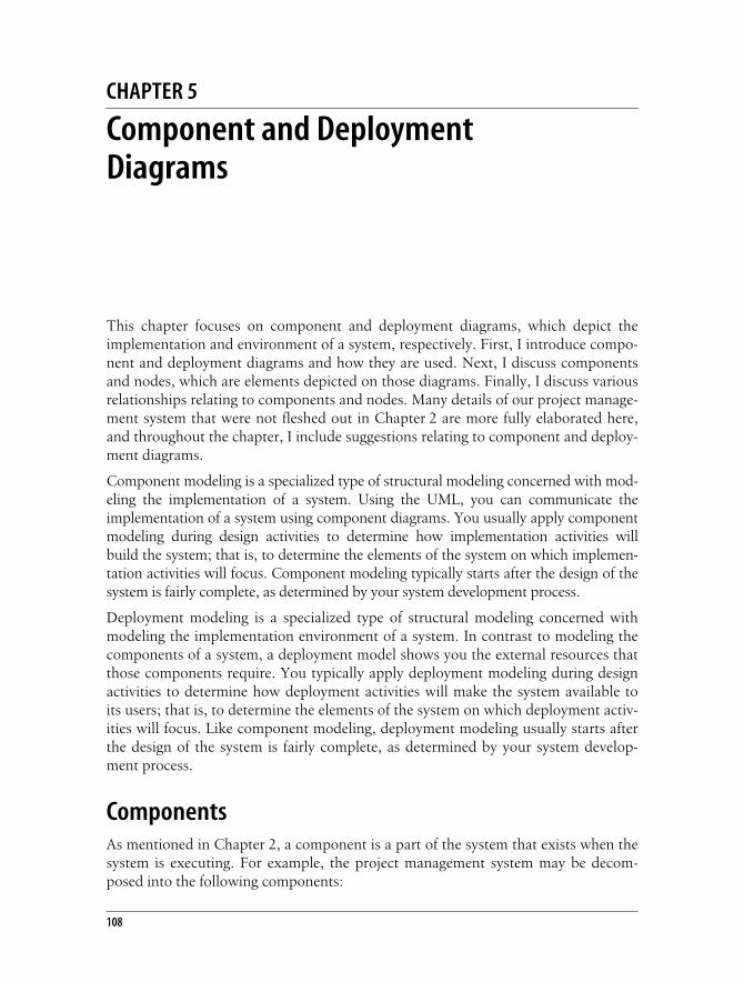
Alternatively, an element that resides inside a component may be shown nestedinside the component. Figure 5-7 shows that the Data subsystem and Utility pack-age reside in the Data component. The Data subsystem is drawn inside the Data com-ponent, while the reside dependency to Utility is still drawn in the same manner asin Figures 5-5 and 5-6.
Notice that the Utility package resides in all the components in Figures 5-5, 5-6,and 5-7, because each component described in those figures has a package that usesthe Utility package. Details of the Utility package are discussed in Chapter 3.
Use DependenciesA use dependency from a client component to a supplier component indicates thatthe client component uses or depends on the supplier component. A use dependency
Figure 5-5. Reside dependencies for packages
Figure 5-6. Reside dependencies for subsystems
User Interface
Utility
User Interface<<reside>>
<<reside>>
<<subsystem>>Business Processing
Utility
Business Processing<<reside>>
IBusinessProcessing
<<reside>>
This is the Title of the Book, eMatter EditionCopyright © 2003 O’Reilly & Associates, Inc. All rights reserved.
114 | Chapter 5: Component and Deployment Diagrams
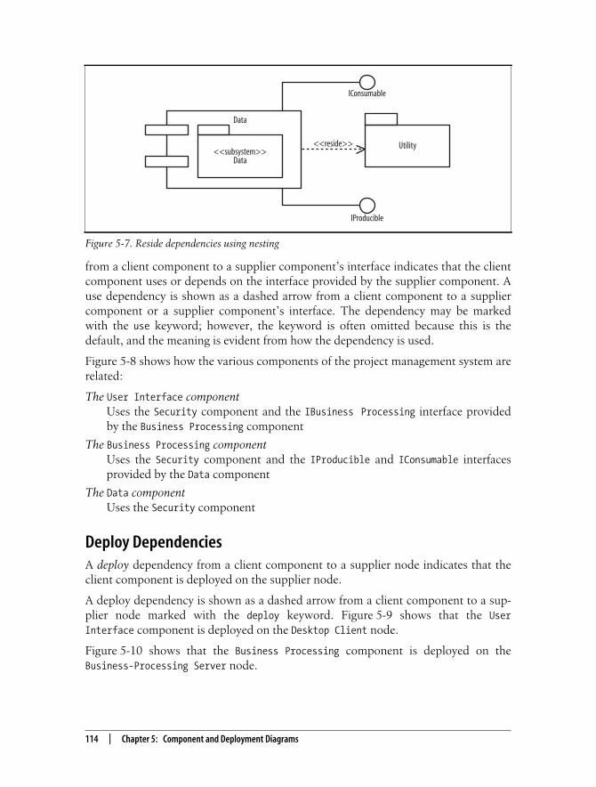
from a client component to a supplier component’s interface indicates that the clientcomponent uses or depends on the interface provided by the supplier component. Ause dependency is shown as a dashed arrow from a client component to a suppliercomponent or a supplier component’s interface. The dependency may be markedwith the use keyword; however, the keyword is often omitted because this is thedefault, and the meaning is evident from how the dependency is used.
Figure 5-8 shows how the various components of the project management system arerelated:
The User Interface componentUses the Security component and the IBusiness Processing interface providedby the Business Processing component
The Business Processing componentUses the Security component and the IProducible and IConsumable interfacesprovided by the Data component
The Data componentUses the Security component
Deploy DependenciesA deploy dependency from a client component to a supplier node indicates that theclient component is deployed on the supplier node.
A deploy dependency is shown as a dashed arrow from a client component to a sup-plier node marked with the deploy keyword. Figure 5-9 shows that the UserInterface component is deployed on the Desktop Client node.
Figure 5-10 shows that the Business Processing component is deployed on theBusiness-Processing Server node.
Figure 5-7. Reside dependencies using nesting
<<subsystem>>Data
Utility
Data
IProducible
IConsumable
<<reside>>

This is the Title of the Book, eMatter EditionCopyright © 2003 O’Reilly & Associates, Inc. All rights reserved.
Dependencies | 115
Alternatively, a component that is deployed on a node may be shown nested insidethe node. Figure 5-11 shows that the Data component is deployed on the DatabaseServer node.
Figure 5-8. Use dependencies
Figure 5-9. Deploy dependencies
Figure 5-10. Deploy dependencies for a subsystem
User Interface
Business Processing
IBusinessProcessing
IProducible
IConsumable
Data
Security
<<use>>
<<use>>
<<use>>
User Interface<<deploy>>
Desktop Client
Business Processing<<deploy>>
IBusinessProcessing
Business-ProcessingServer

This is the Title of the Book, eMatter EditionCopyright © 2003 O’Reilly & Associates, Inc. All rights reserved.
116 | Chapter 5: Component and Deployment Diagrams
Communication AssociationsFigure 5-3 shows nodes associated with the project management system, but how arethose nodes related? A specialized type of association, called a communication asso-ciation, addresses the question of how nodes are related. (Associations are discussedin Chapter 3.)
A communication association between nodes indicates a communication pathbetween the nodes that allows components on the nodes to communicate with oneanother. A communication association is shown as a solid-line between nodes.Figure 5-12 shows that the Business-Processing Server has a communication associ-ation with the Desktop Client, Printer, and Database Server nodes.
Figure 5-13 combines Figure 5-8 and Figure 5-12 to show how components arerelated to nodes. Notice that if two components are related and reside on differentnodes, the nodes must have a communication association between them to allow thecomponents to communicate; otherwise, the components are not able to communi-cate and be related to one another. For example, if the communication associationbetween the Desktop Client and Business-Processing Server nodes was removed, theUser Interface component could not be related to the IBusiness Processing inter-face and Security component. If the communication association between theBusiness-Processing Server and Database Server nodes was removed, the Data com-ponent could not be related to the Security component, and the Business Processingcomponent could not be related to the IProducible and IConsumable interfaces.
Figure 5-11. Deploy dependencies using nesting
Figure 5-12. Communication associations
IProducible IConsumable
Data
Database Server
Desktop Client
Business-ProcessingServer Database Server
Printer

This is the Title of the Book, eMatter EditionCopyright © 2003 O’Reilly & Associates, Inc. All rights reserved.
Exercises | 117
Exercises1. Describe Figure 5-14: identify components and nodes, and describe the relation-
ships among components and nodes.
2. Describe Figure 5-15: identify the various elements and their relationships.
Update the diagram stepwise to show the following details. After each step,check your answers against the solutions shown in Appendix B:
a. The User Interface package uses the IView and IPrint interfaces providedby the Reporting subsystem.
b. The User Interface and Utility packages resides in a User Interfacecomponent.
c. The Reporting subsystem and Utility package reside in a Reportingcomponent.
d. The User Interface component is deployed on a Desktop Client node.
e. The Reporting component is deployed on a Report Server node.
f. The Desktop Client node is connected to the Report Server node, and theReport Server node is connected to a High-speed Printer node.
Figure 5-13. Communication associations
User Interface
Business Processing
IBusinessProcessing
IProducible
IConsumable
Data
Security
<<use>>
<<use>>
Business-Processing Server
Desktop Client
Database Server
Printer
<<use>>

This is the Title of the Book, eMatter EditionCopyright © 2003 O’Reilly & Associates, Inc. All rights reserved.
118 | Chapter 5: Component and Deployment Diagrams
Figure 5-14. Components and nodes for the project management system
Figure 5-15. Packages and a subsystem
User Interface
Utility
<<subsystem>>Data
IProducible
IConsumable
<<subsystem>>Business Processing
IBusinessProcessing
Desktop Client
User Interface<<reside>>
<<deploy>>
Backup StorageDevice
IPrint
<<subsystem>>Reporting
IView
User Interface
Utility