complimentary webinar wednesday, december 12, · pdf filecomplimentary webinar wednesday,...
TRANSCRIPT

ISOLATOR TECHNOLOGY MANUFACTURING
Design…Qualification…Experience
Featured Speakers:Frank GenerotzkyCorinna Schneider
Complimentary WEBINARWednesday, December 12, 2007
This webinar presents the methods used at Baxter’s Halle, Germany facility for the design and validation/qualification of isolators used for the aseptic production of sterile drug products.

2
Speakers
Mr. Frank Generotzky is recognized as an expert in the field of aseptic manufacturing of parenteral products, and is a frequent presenter at several European Conferences and ISPE Meetings for Sterile Drug Manufacturing. He earned his Diploma for Pharmaceutical Engineering from the University of Applied Science Lippe / Höxter in Germany.
Since 1996 Frank has designed and installed several production-lines in standard Cleanroom Technology as well as in Isolator Technology at Baxter’s facility in Halle, Germany. Starting in 2001 Frank headed the production department for sterile cytotoxic drugs (liquid, powders andlyophilisates).
In his present role, Frank is responsible for the strategic development of Pharmaceutical Technology in Halle. He is leading a team of 13 engineers, who design, plan and realize the investment projects in Halle according to customer and market requirements.
Frank GenerotzkyDirector of Technology and Engineering
Ms. Corinna Schneider, is recognized as an expert in the field of sterile drug products produced by aseptic processing. She developed and implemented a complex VHP sterilization process for isolators and equipment parts in Halle/Germany and presented this method at pharmaceutical conferences and workshops in Europe and in the US. She trained local regulatory inspectors in VHP cycle development and presented her concept several times to the FDA. Ms. Schneider earned her Diploma for Pharmaceutical Engineering from the University of Applied Science Lippe / Höxter in Germany.
From 1995 to 2000 she headed the Microbiological Quality Control Lab and focused on environmental monitoring, validation of aseptic processing, and microbial identification. In her current position in Quality Assurance she is responsible for GMP compliance, internal and external auditing, and several compliance projects to improve the effectiveness of the quality management system.
Corinna SchneiderQA Specialist GMP Compliance

3
Topics
Isolator Design Criteria- Different Isolator Applications- Process Development
Qualification of “critical” Design Features- Airflow Investigation Near Mouseholes- Isolator Integrity- VHP Sterilization
Isolator Technology versus Conventional Cleanroom

4
Designing Isolators

5
Different Isolator Applications
Isolators for compounding and Sterilizable isolators for handling of toxic powder aseptic processing
Negative pressure isolators Positive pressure isolators (-50 Pa to -150 Pa) (25 Pa to 100 Pa)
ISOLATORISOLATOR
Isolator for manual sterile Isolators on automatic operations filling machines => “Closed Isolators” => “Open Isolators”
6
Different Isolator Applications Requirements on Containment Isolators
Generally operated under negative pressure to ensure max. operator safety
Typically classified as ISO 7 (Class 10,000 at rest, Grade C)
They must not exchange air with the surrounding environment(except through a HEPA filter)
Equipped with nitrogen supply if required
All materials exiting the isolator must be cleaned or contained
They must be cleanable in a reproducible and quantifiable manner;swab-tests and tracer substances should be used during qualification
7
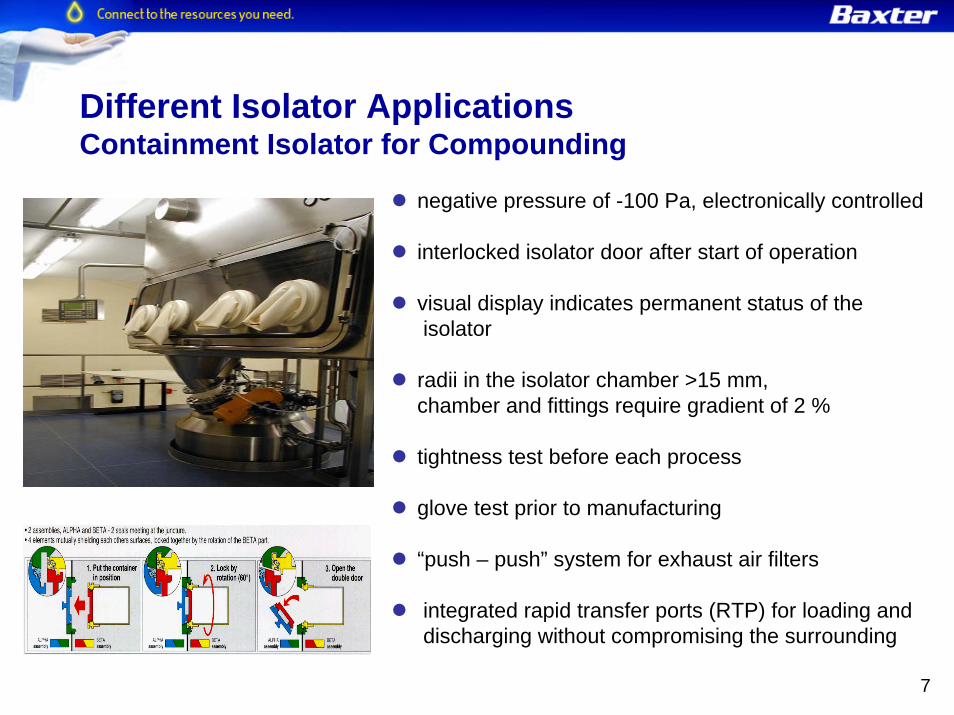
Different Isolator Applications Containment Isolator for Compounding
negative pressure of -100 Pa, electronically controlled
interlocked isolator door after start of operation
visual display indicates permanent status of the isolator
radii in the isolator chamber >15 mm, chamber and fittings require gradient of 2 %
tightness test before each process
glove test prior to manufacturing
“push – push” system for exhaust air filters
integrated rapid transfer ports (RTP) for loading and discharging without compromising the surrounding

8
Different Isolator Applications Requirements on Isolators for Aseptic Processing
They must not exchange air with the surrounding environment except when that air passes though a HEPA filter
Typically classified as ISO 5 (Class 100, Grade A)
These units are typically operated under positive pressure and are subject to sterilization procedures prior to use
They must be sterilized in a reproducible manner (VHP)
All materials that enter the isolator must be sterilized and must enter either directly through a decontaminating or sterilizing system or via a rapid transfer port

9
“Closed Box” with HEPA filter H14
discontinuously loading and discharging
all transfer processes are conducted via aseptic connections (RTP, SIP)
Different Isolator Applications „Closed Isolator“ for Aseptic Operations
Example: Isolator for Aseptic Filling
Isolator: - Grade A, (ISO 5)- VHP sterilization - positive pressure (+ 100Pa)
“Double Door” port-system for aseptic discharging of the isolator

10
G
GInspektionsmaschine
Inspektionsmaschine 3+4
2560
Vials
Inspektionsmaschine2540
Inspektionsmaschine 1+2
2520Inspektionsmaschine
2500Inspektionsmaschine
Ink-Jet
2390
DAR-350
Aussendekonta-minationsanlage
2400
A A
BB
C C
D
D
F
F
E
E
X
-10Pa.
10Pa.
20Pa.
2295Stopfen
Hubs╠ule
Andockstationf╧r Stopfen
2270
H
A B
C
D
E
F
G
4-6Pa.
30Pa.
Different Isolator Applications „Open Isolators“ for continuous Aseptic Operations

11
Different Isolator Applications „Open Isolators“ for continuous Aseptic Operations
Continuous supply with materials during operation, while maintaining Grad A ISO 5
Unidirectional airflow of 0.45 m/s (+/- 0.1m/s)
Safety features:- double wall design - filtration of recirculated air- pneumatic gaskets (controlled and alarmed) - CIP for containment and air ducts- emergency mode including pressure reversal

12
G
G
a-e
0
A A
BB
C C
D
D
F
E
-10Pa.
10Pa.
20Pa.
2295Stopfen
Hubs╠ule
Andockstationf╧r Stopfen
2270
H
D
E
F
G
4-6Pa.
30Pa.
--10 Pa10 Pa
30 Pa30 PaISO 5ISO 5
Classifications:Filling: ISO 5 / Grade ACapping: ISO 7 / Grade CSupport Area: ISO 8 / Grade D
VHP sterilization for ISO 5 / Grade A- stopper bowls included in VHP sterilization- CIP / SIP for filling equipment
Caps and capping equipment:- no sterilisation- controlled disinfection
Environmental Monitoring:- particles 0.5µm, 5.0µm - viable air monitoring - surfaces (RODAC)- Temp, diff. pressure, relative humidity 10 Pa 10 Pa
ISO 7 ISO 7
Different Isolator Applications„Open Isolators“ for continuous aseptic Operations
40 Pa 40 Pa ISO 5ISO 54 Pa4 Pa

13
Zentralanlagevon
H13 H13H14
max. 2 x 1.000 m³/h( während Belüftung nach VHP - Zyklus )
LuftaufbereitungM + P
(inkl. VHP-System)
U15 U15 U15
U15 U15
"Safe change"
"Safe change"
über DachAbluft Umluft
Plenum
Zwischendecke
begehbarTechnikebene
(Tonnendach)
ProduktionsraumKlasse DRaum 21.50
CG - Verteiler
Zentralanlagezur
Überdruck im Isolator 30 Pa
H13"Safe change"
Zentralanlagezur
Different Isolator ApplicationsExample: Design HVAC
Isolators should be equipped with independent HVAC systems

14
Configuration of an Isolator

15
Mock-Up and
Risk Analysis
Process IPC / Monitoring
Qualification / Validation
Cleaning
CIP Reinigung Isolatoren und produktb. Teile
Temperatur, Druck Reinigungszeit Rückstände
Reinigungseffizienz
Changeover
Abfüllmaschine Justage Initiatoren Handschuhtest Beladen Isolatoren
SOP´s reproduzierbare Positionierung BeladungGrenzwerte f. Dichtigkeit
Validierung BeladungGrenzwert Druckabf.
Sterilisation von: - Stopfen - produktberühr. Teile- VHP Isolator
Testrun
Justierung Kalibrierung Filtertest
SOP´s Grenzwerte IPK Waage
Formatbezogene Vorgaben zur Ma-schineneinstellung
Leak tightness
Integrität Isolator Dichtigkeit SIP
Grenzwert Druckabfall Zeit
Qualifizierung der zul. Dichtigkeit
Sanitization
Sterilization
Abfüllmaschine (SIP) Isolator (VHP)
Temperatur , Druck, Menge, Zeit, Differenz-druck
Validierung der VHP Sterilisation und SIP
Set-up
Val
idat
ion
of a
eptic
pro
cess
ing
and
C
lean
ing
Valid
atio
n
before start
Abfüllmaschine Ausrüstung IPK
MA Qualifizierung
Qualifizierung Reinraums
Manufacturing
Füllmenge Monitoring (physik. /mikrobiologisch) v (Luft) p (diff.), T (Luft) rel. Feuchte (Luft), 100% Inspektion
Qualifizierung der Transfersysteme
16
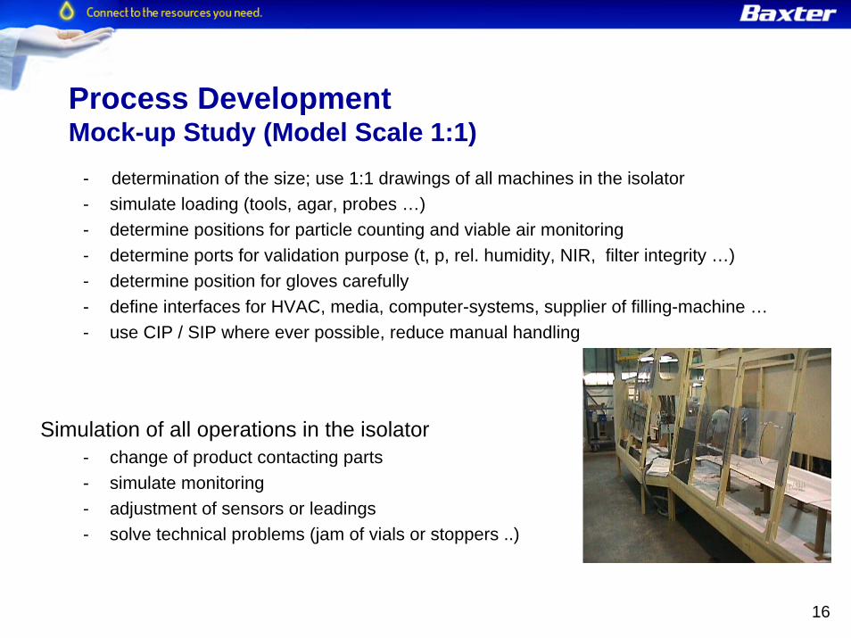
- determination of the size; use 1:1 drawings of all machines in the isolator- simulate loading (tools, agar, probes …)- determine positions for particle counting and viable air monitoring- determine ports for validation purpose (t, p, rel. humidity, NIR, filter integrity …) - determine position for gloves carefully- define interfaces for HVAC, media, computer-systems, supplier of filling-machine …- use CIP / SIP where ever possible, reduce manual handling
Simulation of all operations in the isolator- change of product contacting parts- simulate monitoring- adjustment of sensors or leadings- solve technical problems (jam of vials or stoppers ..)
Process DevelopmentMock-up Study (Model Scale 1:1)

17
Qualification of an Isolator

18
Qualification of “critical” Design Features
Isolators require a high level of qualification and validation with focus on:
Airflow Investigation Near MouseholesIsolator IntegrityVaporised Hydrogen Peroxid (VHP) Sterilization
19
Inspectional Findings: Isolator Qualification(R. Friedmann & J. Agalloco*)
Dynamic filling line conditions not evaluated. Filling line was not in operation during smoke studies.
Smoke studies did not evaluate the pressure changes caused by introducing a glove into the isolator, or retrieving the glove from the isolator.
There was no data documenting isolator airflow parameters, such as air pressurization and velocities, during smoke studies. The acceptability of the lower air pressure limit was not evaluated.
* Presentation by R. Friedman & J. Agalloco; Agallaco & Ass., NJ 2004

20
In this test a concentration of particles with a mean size of approximately 0.5 µm is generated within 5-10 cm of the isolator opening.
The particle concentration should be in the range of 100,000-1,000,000 per m³.
An electronic particle counter calibrated to the 0.5µm particulate size is used to scan the opening from inside the isolator. The particle counts observed on the isolator sideof the opening should not be significantly different from the background count at the same location.
In the measuring location (critical region) the number of particles per unit volume should be less than 0.01% of the initial challenge level to assure absence of airborne microbial contamination under routine operational conditions.
Grade A+30 Pa
Grade C+10 Pa
Qualification of Isolator Integrity near MouseholesPDA TR 34 Appendix B L-R Method

21
Isolator Integrity Leak-Testing
Pressure Hold Test - positive pressure isolators - Test pressure: operating pressure x 2- less than 0.5% of the total volume of the isolator per hour is acceptable
Pressure Drop Test - negative pressure isolators- Test pressure: -200Pa - max. 50 Pa rise of pressure 6 min is acceptable
Gloves (Hypalon 0.8 mm): - Test pressure: 500 Pa after “stressing” the glove - less than 50 Pa in 4 min- supported by physical / microbial qualifications and trend analysis

22
“The VHP decontamination studies for the isolator did not provide an adequate challenge of the cycle to determine the weak points of VHP distribution/ penetration (i.e., where air flow is most variable or potentially compromised).”
“No actual measurements of concentration of sterilant that circulated within the expansive isolator. Only indirect measurements (e.g., internal VHP 1001 generator results for flow rate and H2O2 mg/l) to monitor VHP concentration.”
“Decontamination validation cycle study did not evaluate the actual commercial cycle. Validation runs were conducted at levels which often exceeded the proposed hydrogen peroxide decontamination concentration setpoint of *** mg/l by as much as 30 - 90%.”
VHP SterilizationExamples of Inspectional FDA Findings (R. Friedmann & J. Agalloco)
* Presentation by R. Friedman & J. Agalloco; Agallaco & Ass., NJ 2004

23
“VHP study inappropriately applied fraction negative mathematics to the vaporized hydrogen peroxide process. The fraction negative mathematical approach is fundamentally premised on essentially uniform distribution of the sterilant, and use of replicates.”
“Many worst-case locations were not evaluated. Some examples: - Between fingers of installed isolator gloves. Four of nineteen filling
isolator gloves were evaluated, and only at the outside of the cuff - Occluded surface created by folding the glove into its gauntlet (sleeve)
during the VHP cycle- the stopper bowl locations of most concern (e.g., low point in the bowl)”
VHP SterilizationExamples of Inspectional FDA Findings (R. Friedmann & J. Agalloco)
* Presentation by R. Friedman & J. Agalloco; Agallaco & Ass., NJ 2004

24
Con
ditio
ning
Ste
riliz
atio
n
100 %
H2O
2-C
once
ntra
tion
high
low0 %
rela
tive
hum
idity
CyclePhases
H2O2-Concentration
relative humidity
Condensation
Deh
umid
ifica
tion
Aer
atio
n
VHP SterilizationVHP Process

25
Measurement of Process Parameters
VHP SterilizationVHP Cycle Development
Determination of D-Value
Use of Biological Indicators
Sterilization Target: 12-log-Reduction = overkill Process

26
Temperature • Determination of temperature differences in the Isolator• Reproducibility of temperature profiles
Relative Humidity • Development of conditioning phase: Determination of time to reach max. relative humidity
• Reproducibility of RH-profile
VHP-Concentration • Development of conditioning phase: Determination of time to reach max. VHP concentration
• Reproducible run of concentration curve• Definition of “worst case” environmental conditions:
low gas concentration at low temperatures in the isolator
VHP-Distribution • Uniform distribution of VHP with chemical indicators
VHP-Flow • Unidirectional/turbulent VHP Flow, airflow pattern
VHP SterilizationProcess Parameters

27
Type • Geobacillus stearothermophilus ATCC 12980, 106 spores on stainless steel carrier
Locations • 5 - 10 BIs per m3
• Masked locations like fingers or crinkles of gloves or rails for stoppers
• Documented rationale for each BI location
• Short cycles for identification of worst case locations => non-sterile BIs
VHP SterilizationBiological Indicator

28
No correlation between process parametersand results of BIs !
Determination of worst case locations exclusively based on kill-pattern of BIs !
VHP SterilizationBiological Indicator

29
Survival-Kill-Window Filling Isolator
-7,0-6,0-5,0-4,0-3,0-2,0-1,00,01,02,03,04,05,06,07,0
0 2 4 6 8 10 12 14 16 18 20 22 24 26 28 30t [Min.]
log Population
Survival KillFractional
range
Sterilization Time for a 12-log-Reduction (worst case location):
Sterilization Time(worst case) = Dworst case-Value x 12 = X min
VHP SterilizationDetermination of D-value

30
Requirements for Starting Validation• Completion of all IQ/OQ activities• Completion of cycle development
Validation• 3 runs• Worst case = non operating isolator for min of 12h
Acceptance Criteria• All BIs sterile• Defined H2O2 consumption• Color change of chemical indicator• Room conditions within limits (T, RH)
VHP SterilizationValidation of VHP Sterilization

31
Efficiency and reproducibility of VHP sterilization can only be ascertained and verified using a microbiological system
Individual D-Value determination is required for each isolator based on the “worst case” BI location
VHP SterilizationLessons learned

32
Isolator Technology vs Conventional Cleanroom

33
Isolator Technology Cleanroom Technology Result
=> pro Isolator
Quality of the aseptic environment in the Isolator
Isolator Technology vs Conventional CleanroomExperiences gathered during Manufacturing
Sterility can be maintained more reliable in an reduced aseptic environment with a controlled sterilization method
- VHP sterilization acts sporicidal and validation is possible
- VHP is effective on all accessible surfaces
- Sanitization with Isopropanol / WFI : 70/30 does not act sporicidal, validation is not possible
- Spraying of a disinfectant is less effective

34
Isolator Technology Cleanroom Technology Result
=> pro Isolator
Quality of the “Conventional Cleanroom versus Isolators”:
- Main source of micro organism excluded:the operators
- Process is protected by a solid barrier
- Personnel necessary to run the process
- Process is protected by aseptic techniques and unidirectional air-flow
- Conventional cleanroom technology is more sensitive to human failures
Isolator Technology vs Conventional CleanroomExperiences Gathered during Manufacturing

35
Viable Air Monitoring: Exceeded limits in Grade 100 (ISO 5) Isolators: = 0Exceeded limits in Grade 100 (ISO 5) sterile core area: = 0
Particles (continuous monitoring 0.5µm / 5.0µm): Exceeded limits in Grade 100 (ISO 5) Isolators < 0.001% Exceeded limits in Grade 100 (ISO 5) sterile core area: > 0.01%
Glove, Sleeve, Overall Monitoring:Exceeded limits in Grade 100 (ISO 5) Isolators : = 0 Exceeded limits in Grade 100 (ISO 5) sterile core area: > 0.1%
Surface Monitoring:Exceeded limits in Grade 100 (ISO 5) Isolators: = 0 Exceeded limits in Grade 100 (ISO 5) sterile core area: > 0.1%
Results after 5 years Monitoring
Isolator Technology vs Conventional CleanroomExperiences gathered during Manufacturing

36
Flexibility
Isolator Technology Cleanroom Technology Result
=> pro Cleanroom
Isolator Technology is limited suited for flexible processes with manual handling
- process design flexible
- accessibility not limited
- process design can be adapted to different requirements
- inflexible processes
- poor accessibility
- limited feasibility for handling and transfers
Isolator Technology vs Conventional CleanroomExperiences gathered during Manufacturing

37
Reduced costs for maintaining Class 100
Economic Efficiency
Isolator Technology Cleanroom Technology Result
=> pro Cleanroom
=> Isolator
=> Isolator
Mechanical trouble leads to termination of processes
More flexibility regarding troubleshooting
Risk of losing batches is lower in a conv. cleanroom
Reduction of costs for environmental monitoring and gowning possible
High costs for energy,environmental monitoring and gowning
Operating in three shifts is possible
Daily disinfection andrecovery time is required.
Increased overall time for operations
Isolator Technology vs Conventional CleanroomExperiences gathered during Manufacturing
38
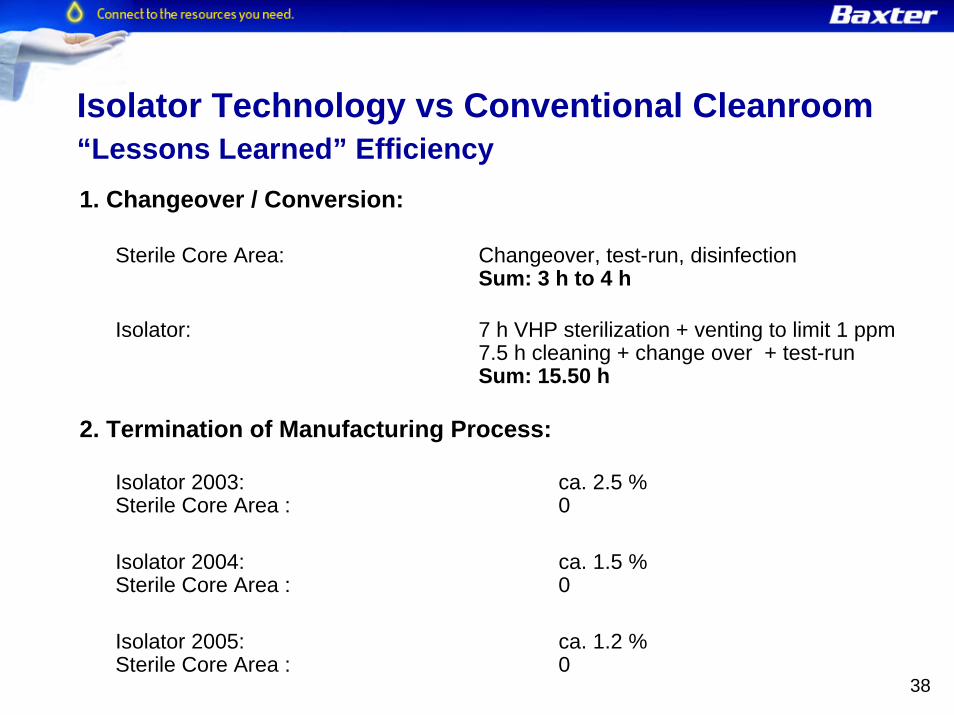
1. Changeover / Conversion:
Sterile Core Area: Changeover, test-run, disinfectionSum: 3 h to 4 h
Isolator: 7 h VHP sterilization + venting to limit 1 ppm7.5 h cleaning + change over + test-runSum: 15.50 h
2. Termination of Manufacturing Process:
Isolator 2003: ca. 2.5 %Sterile Core Area : 0
Isolator 2004: ca. 1.5 % Sterile Core Area : 0
Isolator 2005: ca. 1.2 % Sterile Core Area : 0
Isolator Technology vs Conventional Cleanroom“Lessons Learned” Efficiency

39
Summary …
Would we choose Isolator Technology again ?
Yes regarding maximum achievable product qualityYes regarding operator safety (EHS)Yes regarding process complexity and process stabilityYes regarding economic efficiency
Is the isolator basically the best concept for aseptic processing ?
Not always ... but more and more!
…after five years experience with Isolator Technology designed and build for the supply of the world wide market with cytostatics
http://www.baxterbiopharmasolutions.com/contract_manufacturing/facilities_equipment/halle_germany.html