complex for simulation modeling of the dynamics of dosing
TRANSCRIPT
Modern Applied Science; Vol. 9, No. 6; 2015 ISSN 1913-1844 E-ISSN 1913-1852
Published by Canadian Center of Science and Education
266
Complex for Simulation Modeling of the Dynamics of Dosing Systems
Almaz Mullayanovich Khanov1, Alexey Efimovich Kobityansky1, Alexey Vladimirovich Shafranov1 & Mihail Vladimirovich Kuznetsov1
1 Perm National Research Polytechnic University, Russia
Correspondence: Almaz Mullayanovich Khanov, Perm National Research Polytechnic University, 614990, Perm, Komsomolsky prospekt, 29, Russia.
Received: December 15, 2014 Accepted: March 14, 2015 Online Published: May 30, 2015
doi:10.5539/mas.v9n6p266 URL: http://dx.doi.org/10.5539/mas.v9n6p266
The research is carried out with the financial support of the Ministry of education and science of the Russian Federation on the State assignment (design part) No. 9.1570.2014/K.
Abstract The design of dosing systems with regard to the engineering and design requirements based on the system approach is a relevant and important issue for various industries. Stage modeling of such systems is one of the main issues in the design process. The purpose of work is development of complex for simulation modeling of systems of volumetric dosing of liquids. Realization of this goal is based on a combination of fundamental and computational schemes of functioning of dosing systems; mathematical models taking into account the dynamic relationships of their elements in different modes of operation and software for the study of these models. The structure of the complex is given. Using the diagrams the interaction of the elements of the metering system is shown and the relevant mathematical relationships present. As an example, dynamic phenomena processes dosing for hydraulic and mechanical drive of the executive body of the metering system are described. The algorithm of calculation of dynamic characteristics of dosing systems is developed on the basis of which the proposed software for mathematical modeling in the environment of Matlab using integrated numerical algorithms for solving systems of differential equations by the Runge-Kutta method of 4th and 5th order. Some results of calculations of the dynamic characteristics of the dispensing process for cases hydraulic, and the Cam actuator of the Executive body of the dispenser are shown. A graphical illustration of the results obtained is given and the comparison of the dynamic characteristics of dosing systems for the types of drives that allows their evaluation and selection of one or another construction in accordance with specified requirements is given. System for simulation modeling allows you to implement a directed study of the dynamics of dosing systems with access to the solution of problems of optimal design and synthesis.
Keywords: dosing system, dosing, mathematical model, simulation modeling
1. Introduction Dosing systems provide precise dosing of those or other products to perform certain technological processes due to the change and variation of parameters and characteristics of these systems. The role of dosing systems has increased dramatically in modern manufacturing. They got the greatest dissemination and practical application in the chemical, oil refining, machine building, aviation, medical and other industries. A number of companies deals with production metering pump, which confirms the relevance of such devices when performing various processes (Sveshnikov, 2001). Among such systems are important system volumetric dosing of liquids (Sokolov, 1987), the synthesis of which is a complex engineering task, requiring consideration sets and the relationship of technological, structural and ergonomic requirements (Skhirtladze, 2003). The choice of a rational or optimal parameters of the elements of the metering pumps that meet the above requirements, is one of the most important steps in their synthesis (Grigoriev, 2011) and can be implemented using a complex simulation. Using such complexes appears possible, without resorting to expensive experiments on a real object, to solve problems of complex system design, analysis and evaluation processes of their operation by setting simulation experiments on the computer (Strigalev, 2008). This allows to take into account at the stage of design calculations of structural features of the object, constructive solutions and provides an in-depth study of the behavior of the

www.ccsenet.org/mas Modern Applied Science Vol. 9, No. 6; 2015
267
modeled system as a whole in relation to all of its elements (Law, 2000). In addition, on the base of a simulation experiments in the calculation process can be refined parameters and design features of the object in accordance with the implemented processes. In the work conducted a design diagram and mathematical model of batching systems is present, taking into account the interrelation of all their elements as a whole (Khanov, 2012), which differ from the known studies of a number of authors who review the properties of individual elements of the design outside with regard to their dynamic relationships. We derived mathematical models (Khanov, 2013) that take into account the different types of actuators of Executive bodies of the dispensers and have non-linear and variable structure. The need arose for the use in process modeling numerical methods of calculation (Roache, 1998). Such calculation methods are implemented on the basis of universal methods and programs (Anderson, 2011). The use of complex of simulation modeling provides the most detailed description of the processes dosing by taking into account the characteristics of each element, their relationships and flexible controllability calculations.
2. Methodology The object of the research and modeling are the dispensers of liquid reagents with hydraulic or mechanical drive elements which are dynamically interrelated. To realize the process of modeling there is a complex for simulation modeling, representing a combination of structural, functional and design schemes, mathematical models and software for the study of the dynamics of dosing systems.
2.1 Structural-Functional and Design Scheme of Dosing Systems
At the initial stage of research and the formulation synthesis of dosing systems their structural-functional scheme based on the generalized classification are formed (Khanov, 2012). At the same time the constructive-technological requirements are taken into account and a number of basic criteria for the operation of metering systems is assigned, such as the dosing accuracy, speed, amount of dose, productivity, cycle, reliability, durability, etc. It should be noted that the introduction of complex integral criterion, consisting of a combination of individual criteria with their weights according to their degree of significance, is possible. Thus structural-functional relationships are formalized and the relationship of all elements of the system as a whole is considered. As an example, Figure 1 shows one of the larger variants of the structural-functional scheme with a drive motor of the whole structure dispensing systems.
Figure 1. Schematic diagram of the operation of metering systems
The power from the power supply is supplied to the electric motor and control system. The motor transmits motion to the drive transmission mechanism which converts the rotation of the rotor of the electric motor in a desired motion of the Executive body of the dispenser. The Executive body implements the supply of feed material through the dispenser to the consumer. The feedback of the controller with the elements of the metering system is provided using a measuring device and other elements of the control system.
The individual items of such scheme in the synthesis process can be clarified, in particular, the drive unit of the Executive body of the dispenser of the transmission mechanism, the role of which can perform a variety of hydraulic, pneumatic or mechanical devices, most often used in the design of dosing systems. The functional structure of dosing system with a hydraulic actuator of the Executive body presented in Figure 2 illustrates this. The hydraulic actuator may be implemented, for example, on the basis of centrifugal or gear pump.

www.ccsenet.org/mas Modern Applied Science Vol. 9, No. 6; 2015
268
Figure 2. Structural-functional scheme of the system with a hydraulic actuator of the Executive body of the
dispenser
1 – the drive unit; 2, 3 – discharge and overflow chambers of the power cylinder; 4, 5 – discharge and overflow chamber of the metering cylinder; 6 – check valve; 7 – consumer reagent; 8 – tank with the reagent
Functional diagrams are the basis for creating design data of dosing systems and their mathematical models according to the given requirements. In Figure 3, as an illustration, presents a design scheme of a power metering system with a centrifugal or gear pump to drive the plunger of the dispenser.
Figure 3. Calculation circuit system with hydraulically driven Executive body of the dispenser
Elements 1, 2...8 conform to the notation of Figure 2. It should be noted that the link I characterizes the system with a centrifugal pump, the link II is a system with gear pump.
During operation the pump creates a flow of the working fluid flowing into the pressure cylinder chamber. Due to increased pressure of the working fluid in the pressure cavity, there is overcoming of the resistance forces on the piston (plunger), thereby ensuring its forward movement. In the chamber of the dispenser there is the increase in the fluid pressure with the subsequent opening of the valve at the outlet to the consumer. After release of the reagent pressure in the chamber of the dispenser is aligned, the valve is closed.
Reverse is accomplished by turning off the electric pump so that the pressure in the discharge chamber of the cylinder is aligned. Under the action of the elastic force of the spring the piston-plunger returns to its original position. Due to the forward pressure from tank with the reagent, the valve opens and the camera dispenser is filled with a new portion of the reagent.
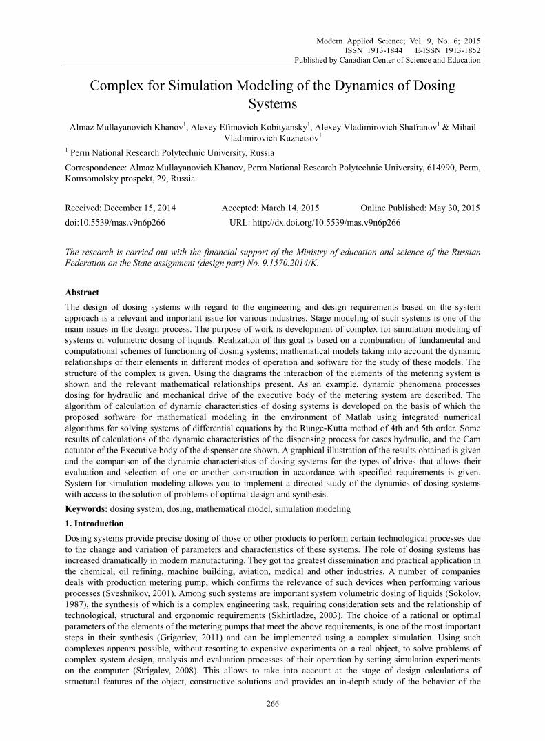
Figure 4 shows, as an example, the calculation scheme dispensing systems with the Cam drive of the Executive body of the dispenser. The use of a Cam actuator allows for the appropriate form of the Cam profile to generate the necessary law of motion of the Executive body of the dispenser, ensuring smooth work, fixed duration idling and working strokes and the desired stability of the flow of dosed substance.
www.ccsenet.org/mas Modern Applied Science Vol. 9, No. 6; 2015
269
Figure 4. The calculation scheme of the system with the Cam drive of the Executive body of the dispenser
The rotation of the rotor of the motor through a gear mechanism (if any) is transmitted to the Cam shaft. The Cam profile provides a specified law of a reciprocating motion of the plunger-plunger. In the delete phase, due to the low compressibility of the liquid in the chamber of the dispenser there is a significant increase in the pressure. Due to the pressure differential between the consumer and the camera metering device, there is the opening of the valve and subsequent dosing. Further there is the alignment of pressure and closing of the valve. On the phase of convergence there is filling the chamber of the dispenser from the supply tank located at a certain height.
2.2 Generalized Mathematical Model and Software Features of the Volumetric Dosing
Mathematical models of systems of volumetric dosing of liquids are based on the principle of the composite model with the following main hypotheses and assumptions (Broecke, 2008): working and dosed fluids are compressible and the walls of the cylinder and the cylinder of the dispenser are pliable; the piston of the hydraulic cylinder and plunger of the dispenser form a rigid whole, the system operates in a bath of oil without hydraulic losses between the areas separated by the piston and the plunger; the full mechanical characteristic of the motor of the whole object is considered.
The result is a generalized mathematical model that takes into account the relationship of the parameters and characteristics of dynamic processes, as well as various modes of operation of the metering system complex electrohydromechanical patterns described by the system:
Y F= (1)
However, taking into account the above calculation schemes (Figures 3 and 4) the following indicators of vector-column Y , yi, (i=1…8) are introduced:
• y1=[phi] – angle of rotation of the motor rotor, rad;
• y2=[omega] − angular velocity of the motor rotor, rad/s;
• y3=x − displacement of the plunger, m;
• y4=v − speed of the plunger, m/s;
• y5=ppow – pressure in the power unit (in the case of a mechanical drive ppow=0), Pa;
• y6=pdisp – pressure in the dispenser, Pa;
• y7, y8 – pressure in the discharge chambers of the power cylinder and the dispenser, respectively, Pa.
The right part of the system (1) is a column vector whose elements Fi (i=1…8) consist of a combination of previously entered ID and constructive-technological and operational parameters of the metering system (the diameters of the cylinders, the outlet pressure, the parameters and mode of operation of the motor and other).
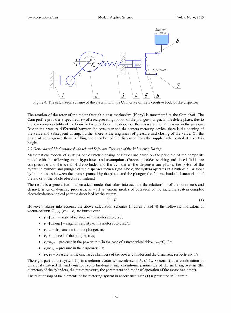
The relationship of the elements of the metering system in accordance with (1) is presented in Figure 5.
www.ccsenet.org/mas Modern Applied Science Vol. 9, No. 6; 2015
270
Figure 5. The relationship of the elements of the metering system
Here Mresist − given the drag torque on the motor shaft, N⋅m;
Ffric − the friction force, N;
Q1, Q2 − the flow in the discharge and supply lines, m3/s;
psupply, ppress − the pressure in the supply and delivery lines, respectively, Pa.
According to this relationship mutual influence of elements of the metering system is viewed, contributing to the further formation algorithm for the solution of system (1).
It should be noted that due to the number of auxiliary factors calculations are carried out for various types of drive of the Executive body of the dispenser. The process of selecting the type of drive is implemented using the function control D:
1, hydraulic fluid power
0, power transmissionD
=
(2)
In the result of a mathematical transformation elements of vector F take the following form:
( ) ( )
( )
( )( )
2
driv 2 resist 1 2 5 6
1 4
2
3
4
5 2 2 1 4
6 elast1 pow 1 3
7 2 4 1 2
8 elast2 disp 2 3
confl.pow
confl.disp
1( ) , , ,
i
y
M y u t i M y y y yI
F yF
F a DF
FF g y A y
DF K V A y
F A y Q QF K V A L y
F
F
⋅ ⋅ − ⋅ = = ⋅ − ⋅ ⋅ Δ + ⋅ ⋅ − +
⋅ Δ + ⋅ −
Δ
Δ
, (3) where ΔVpow (ΔVdisp) − the “dead” volume of a cylinder (dispenser), m3;
u(t) − function control mode of operating cycle/blank run:
1, operating cycle
0, blank runu
=
, (4)

www.ccsenet.org/mas Modern Applied Science Vol. 9, No. 6; 2015
271
i − gear ratio (if available); I − converted to a motor shaft moment of inertia of the movable parts, kg⋅m2; Mdriv − driving moment of electrical engine, N⋅m; L − maximal drive of shaft, m.
The acceleration of the piston of the dispenser a is determined from the following conditions, m/s2:
( ) 4driv fric 4
4 driv fric
4 driv fric
01sign ,
0,
0, 0,
yP F y
y P Fa m
y P F
≠− ⋅ = >=
= ≤
, (5)
where m − the reduced mass of the movable parts to the stock, kg; Pdrive − driving force, N:
8
driv 0 35
( )j jj
P A y c x y=
= ⋅ − ⋅ + , (6)
here c − stiffness coefficient of the spring return, N/m; x0 − is the value of the pre-compression of the return spring, m.
Ffric − the friction force, N:
80
fric fric4
j jj
F F B y=
= + ⋅ , (7)
where Ffric0 − the static friction force, N.
The values of coefficients A , B , elastK , dependent on the material and the parameters of the nodes of the dispenser and properties of the dosed material are summarized in the vector-columns:
1
2
3
4
0
0
0
0,A
A
A
A
A
=
− −
pow disp
pow pow pow
disp disp disp
pow pow pow pow
disp disp disp disp
0
0
0
,2
2
( ) 2
( ) 2
h hB
f d H
f d H
f d d H
f d d H
ππ
ππ
+ = ⋅ ⋅ ⋅
⋅ ⋅ ⋅ ′⋅ ⋅ + ⋅ ′⋅ ⋅ + ⋅
pow pow.liquidpow.liquid
pow pow.wall
elast
disp disp.liquiddisp.liquid
disp disp.wall
1
,
1
d EE
S EК
d EE
S E
⋅+ ⋅ =
⋅ + ⋅
(8)
where A1, A2, A3, A4 − is the cross-sectional area of the power part of the cylinder chamber of the dispenser, the discharge chamber of the power cylinder and the dispenser, respectively, m2; hpow (hdisp), fpow (fdisp), dpow (ddisp), d′pow (d′disp), Hpow (Hdisp), Spow (Sdisp), Epow.liquid (Hdisp.liquid), Epow.wall (Hdisp.wall) − is the kinematic coefficient of viscosity of the fluid [m2/s], the friction coefficient of the pair cuff-cylinder, the diameter of the cylinder [m], the diameter of the discharge side of the cylinder [m], height cuff [m], the wall thickness of the cylinder [m], the modulus of elasticity of the fluid [Pa], the modulus of elasticity of the material of the cylinder [Pa] power part (batcher), respectively.
The cost of the liquid in the discharge and supply lines are described by the following relations:
press 6
1press 6 press 4 6
0,
,
p yQ
G y p p y
≥= ⋅ − <, (9)
6 supply
2supply supply 6 6 4
0,
,
y pQ
G p y y p
≥= ⋅ − <, (10)
where Gpress, Gsupply − the values of conductivity of check valves for the inlet and the feed line, respectively, m4·s-1·N-0.5.
Changes of pressure ΔFconfl.pow и ΔFconfl.disp in the overflow chambers of the cylinders are taken constant (ΔFconfl.pow=ΔFconfl.disp=0).
The moment of resistance Mresist is determined depending on the type of drive ratios:
www.ccsenet.org/mas Modern Applied Science Vol. 9, No. 6; 2015
272
1 5 0resist
resist.mech
( ), 1
, 0ig y p D
MM D
⋅ − == =
, (11)
where p0 − pressure at the pump inlet, Pa.
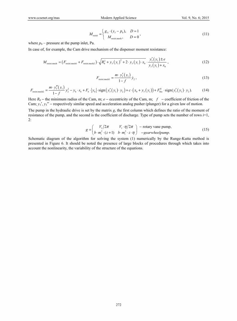
In case of, for example, the Cam drive mechanism of the dispenser moment resistance:
( ) ( ) ( ) ( )( )
2 3 12resist.mech resist.mech1 resist.mech2 0 3 1 3 1 0
3 1 0
2y y e
M F F R y y y y xy y x
′ ±= + ⋅ + + ⋅ ⋅ ⋅
+, (12)
( )3 1resist.mech1 21
m y yF y
f
′⋅=
− , (13)
( ) ( )( ) ( )( ) ( )3 1 2 0resist.mech2 2 6 6 6 6 3 1 2 0 3 1 fric 3 1 2sign sign( ).
1
m y yF y y s F y y y y c x y y F y y y
f
′′⋅′ ′= − ⋅ + ⋅ ⋅ ⋅ + ⋅ + + ⋅ ⋅
− (14)
Here R0 − the minimum radius of the Cam, m; e − eccentricity of the Cam, m; f − coefficient of friction of the Cam; y3′, y3′′ − respectively similar speed and acceleration analog pusher (plunger) for a given law of motion.
The pump in the hydraulic drive is set by the matrix g, the first column which defines the ratio of the moment of resistance of the pump, and the second is the coefficient of discharge. Type of pump sets the number of rows i=1, 2:
1 12 2
2 2 rotary vane pump,
( 1) .t t
V Vg
b m z b m z gearwheelpump
π η πη
⋅ − = ⋅ ⋅ + ⋅ ⋅ ⋅ −
(15)
Schematic diagram of the algorithm for solving the system (1) numerically by the Runge-Kutta method is presented in Figure 6. It should be noted the presence of large blocks of procedures through which takes into account the nonlinearity, the variability of the structure of the equations.

www.ccsenet.org/mas Modern Applied Science Vol. 9, No. 6; 2015
273
Figure 6. Schematic diagram of the algorithm of computation of dispensing systems
In block 1 the increase in the angular speed of the pump is determined, taking into account the mechanical characteristics of the motor (block 2), the action of the torque from the pump or the Cam associated with the rotor of the motor via a gearbox.
Unit 3 determines the change of fluid pressure in the power section of the dispenser of the equation, compressibility, or in the case of a mechanical drive increment equals 0.
Box 4 describes the dynamics of the moving parts of the dispenser under the action of the driving force from fluid pressure or rotation of the Cam and forces from moving parts and friction of inner fluid.
In block 5 the obtained value of the speed of the plunger integrates and determines the movement of the piston.
Macroblock "Supplyvalve" calculates a pressure differential dispenser-supply tank, obtained from the previous step of integration, the fluid flow through the valve coming from the tank with the reagent.
Macroblock "Pressvalve" similar to above unit calculates the flow rate of fluid coming from the chamber of the dispenser in the consumer, provided that the excess pressure in the dispenser above the pressure in the consumer.
Block 6 is the adder of costs and integrating its results determines the performance of the system per cycle.
Block 16 defines the conditions for the completion of the integration process, which is a physical limitation when the piston reaches the end of its stroke and software – the maximum time allotted to avoid infinite loops when the piston cannot reach the end of the stroke within a reasonable time, for example when its vibrations, when the pressure in the consumer too great to overcome.
The results of the decision (block 17) are the vector of desired values in the specified reference points, the cycle time, the volume of fluid received from the tank and the consumer, which may not be equal due to the compressibility of the fluid and the deformation of the cylinder barrel of the dispenser. The received data is
www.ccsenet.org/mas Modern Applied Science Vol. 9, No. 6; 2015
274
transferred as initial conditions for the next cycle of dosing.
Numerical experiment of the dynamics of the dispensing process model (1) is implemented using software, based on the use of MATLAB R2012b, forming completely with the above schemes the complex simulation of the dynamics of the metering system. Integrated procedures for solving systems of differential equations numerically by the Runge-Kutta method of 4th and 5th order with automatic step of selection and application of the interpolator (scheme Dormand and Prince, RK5(4)7FM, DOPRI5, DP(4,5), DP54) (Shampine, 1997) were used.
Taking into account the initial condition, for example, the following basic data are entered: the type and parameters of the actuator of the Executive body of the dispenser; stroke of piston, m; diameter of cylinder, m the mass of the piston, kg; is the modulus of elasticity of the material power and the dosing cylinders, Pa; bulk modulus of the fluid in the power section and dosed substances, Pa; kinematic coefficient of viscosity of the fluid, m2/s and other.
3. Results Software with intuitive interface is implemented on the basis of the developed algorithm of calculating the basic dynamic characteristics of the dispensing process (Figure 6). The calculations in the process of the numerical experiment are formed in the form of convenient tables of input data and the results of mathematical modeling are represented by tables, graphs and animations, allow for the estimation of dynamic phenomena.
To speed up the process of calculation extension package MATLAB Parallel Computing Toolbox and Distributed Computing Server are used that contains the component of the distributed parallel computing, whereby the speed of calculation is increased by utilizing computing power of a single computer (using all CPUs) and/or multiple computers in a computing cluster.
Along with parallelization to improve performance software system provides the choice of method for solving integral equations, which affects the accuracy and speed of convergence. This feature is used to speed up approximate calculations, then using a high-precision method for solving for more accurate results.
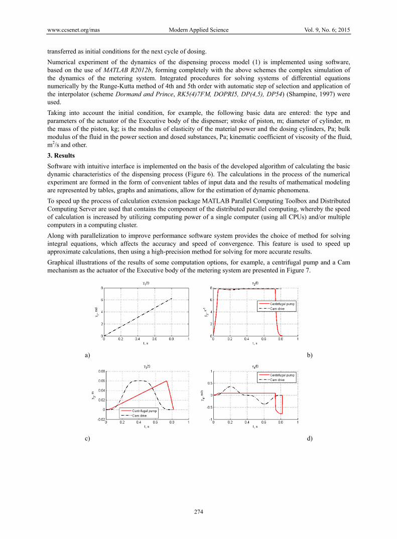
Graphical illustrations of the results of some computation options, for example, a centrifugal pump and a Cam mechanism as the actuator of the Executive body of the metering system are presented in Figure 7.
а) b)
c) d)

www.ccsenet.org/mas Modern Applied Science Vol. 9, No. 6; 2015
275
e) f)
g) h)
i)
Figure 7. Dynamic characteristics of the dispensing system with centrifugal pump and the Cam drive of the Executive body
In the calculations we obtained the following main characteristics: temporal dependence of the kinematic parameters of the movement of the plunger of the dispenser and its speed; change of pressure in the cylinders and flow of the metered fluid over time.
For centrifugal pump is characterized by a linear increase in displacement with the abrupt stop of the plunger (Figure 7, c). The pressure change in the power of the pump and the dispenser (Figure 7, f, g) for the case of a centrifugal pump is also characterized by a sharp change in the initial and final stages of the movement. The change in the flow rate (Figure 7, h) is constant, except for the jump at the start and end point of one cycle of operation.
For dispensing systems with the Cam actuator plunger is characterized by its unstressed move (Figure 7, c). The pressure in the dispenser has a smooth law changes due to the Cam profile (Figure 7, g), which was selected on the basis of the polynomial law of motion of the seventh degree of the pusher (plunger). The fluid flow in the inlet and the supply lines change smoothly (Figure 7, h). In addition, the driving torque on the Cam Mdrive in the dispensing process changes smoothly (Figure 7).
In both cases, for the given initial data, it is theoretically possible to realize a rather considerable pressure to 40-45 MPa.
Thus, it is possible the comparison and evaluation of the application of those or other structures for realization of the given process of dispensing liquids.
4. Discussion In the work (Bashta, 2013) calculation of mathematical models of volumetric cylinders is made, which are
www.ccsenet.org/mas Modern Applied Science Vol. 9, No. 6; 2015
276
usually part of the dispenser. In (Sheypak, 2009) the characteristics of only one of the elements of the dispenser are identified. To calculation and application of volumetric pumping units work is devoted (Britain, 2004), which is the clarification and identification of the basic concepts characteristic of hydromachines dispensing liquids. In this work recommendations when designing pumps for more accuracy, stability and cycle stability are given. (Kolisnichenko, 2005) Recommendations for configuring and numerical modeling in the Ansys CFX for the study of the pattern of the flow only for a flowing part of the pumps the slurry are given. The model containing the pump, cylinder and system linking their sockets, taking into account the compressibility of the liquid without consideration of the engine, valves and control systems is presented in (Andrienko, 2007). In the work (Chimenti, 2004) there is discussed the dynamics of the pump which can be taken as only one element of a dispensing systems. It should be noted that a number of authors also takes into account the compressibility of the fluid and offers solutions for an explicit scheme "classics", MC-Cormack, Dufort-Frankel, Brailovsky, Allen Chen, Lax-Veroff. All circuits have limitations on the maximum size of the time step resulting from the stability condition. For automated design of a hydraulic actuator used in engineering (Ermakov, 1988) and carrying out computer calculations presents a set of handy for programming on the PC only certain elementary mathematical models of hydraulic elements (Malinowski, 1980): piston pump, hydraulic motor, valves, hydraulic cylinder, the pipe section.
The analysis showed that upon the design of dosing systems systematic approach is poorly understood that takes into account the dynamic interrelation of all their elements. The technique of synthesis of dispensing systems optimal structure based on a generalized mathematical models using appropriate software is insufficiently developed.
5. Conclusion According to the results presented in the article, you can make the following conclusions.
1) Developed complex for simulation modeling of the dynamics of dosing systems consisting of interconnected, complementary parts and providing a systematic approach to the study and design of the dispenser.
2) Functional and design scheme of the system make it possible to create a generalized mathematical model of dosing systems that meet the structural and technological requirements for various types of drive of the Executive body of the dispenser.
3) The software in the process of the numerical experiment in the automatic mode allows you to conduct a quantitative assessment of the dispensing process, and the assessment of the suitability of the design of the dispenser.
4) The software of complex has a research tool for space factors with saving of obtained graphical results and report file generation, ranging factors value, which allows on the basis of these results to evaluate the influence of parameters, and conduct a targeted search of their rational or optimal values.
5) Effective tool for execution of oriented mathematical simulation of dynamic processes is got during research and synthesis of dose systems.
Appliance of this complex is possible for volumetric liquid additive metering systems.
Under the preceding hypothesis problem to practical realization of obtained results in the form of real design solutions and separate constructions is set.
On the basis of the presented results in the further work it is planned to carry out optimum designing and is constructive-technological synthesis dispensing systems satisfying shown operational requirements. The received results are realised in the form of concrete design of the dispensers and multipurpose stands for their tests.
References Anderson, D., Pletcher, R., & Tannehill, J. (2011). Computational fluid mechanics and heat transfer (3th ed.).
New York: CRC Press.
Andrienko, P. (2007). Method of forming a dynamic model of the hydraulic transmission. Theory of Mechanisms and Machines, 2(5), 52-62.
Basta, T. et al. (2013). Hydraulics, hydraulic machines and hydraulic drives: A textbook for colleges. Moscow: Alliance.
Bazhin, I., Bernhard, Yu., & Gaitsgory, M. et al. (1988). Automated design engineering hydraulic. Under the General editorship of S.A. Ermakova. Moscow: Mechanical engineering.

www.ccsenet.org/mas Modern Applied Science Vol. 9, No. 6; 2015
277
Britvin, L. (2004). Development of scientific bases of construction, calculation and application of multifunctional volumetric pump units. Dissertation. Moscow: MADI.
Bruecke, E., & Kostin, A. (2008). A method of numerical solution of the Navier-Stokes equations in a variable speed pressure. Applied hydromechanics, 2(10), 13-23.
Chimenti, M., Varela, L., Forteza, E., & Favaloro, R. (2004). Computational fluid dynamics analysis of a novel axial flow blood pump with two counter-rotating impellers. Mecanica Computacional, 23, 1483-1489.
Grigoriev, S., & Fungi, A. (2011). Mathematical modeling of optimal batch dosing materials. Engine, 7, 16-18.
Khanov, A., Kobityansky, A., Shafranov, A., & Petrov, D. (2012). Mathematical model of dispensing systems. Proceedings of Samara scientific center of Russian Academy of Sciences, 4(5), 1329-1334.
Khanov, A., Kobityansky, A., Shafranov, A., Petrov, D., & Kuznetsov, M. (2013). Modeling the dynamics of dosing systems with hydraulic drive. Proceedings of Samara scientific center of Russian Academy of Sciences, 6(2), 528-532.
Kolisnichenko, E., & Kocevski, A. (2005). Possibility and prospects of studying the workflow of pumps, pumping the slurry, using data calculated experiment. Bulletin of Sumy State University, Technical science, 12(84), 71-77.
Law, A., & Kelton, W. (2000). Simulation modeling and analysis (3th ed.). McGraw-Hill.
Lepeshkin, A., Mikhailin, A., & Sheypak, A. (2009). Hydraulics and hydraulic pneumatic actuator: textbook for universities in 2 parts. Part 2: Hydraulic machines and hydraulic pneumatic actuator. Ed. by A.A. Shabaka. Moscow: Publishing house of MGIU.
Malinovsky, E., Zaretsky, L., Bernhard, Y., & Gaitsgory, M. et al. (1980). The Calculation and design of building and road machines on ECM. Ed. by E.Y. Malinovsky. Moscow: Mechanical engineering.
Roache, P. (1998). Fundamentals of Computational Fluid Dynamics. Albuquerque: Hermosa Publishers.
Shampine, L., & Reichelt, M. (1997). The MATLAB ODE suite. SIAM Journal on Scientific Computing, 18, 1-22.
Skhirtladze, A., Ivanov, V., & Karev, V. (2003). Hydraulic and pneumatic systems: textbook for universities. Second edition, enlarged. Moscow: MSTU "STANKIN".
Sokolov, M., & Gurevich, A. (1987). Automatic dosing of liquids. Leningrad: Chemistry.
Strigalev, B., & Tolkacheva, I. (2008). Acting simulation: Textbook. Moscow: MSTU after N.E. Bauman.
Sveshnikov, V. (2001). Hydraulic equipment: in three books. The international Academy of Informatization, International Handbook. Book 1: Pumps and hydraulic motors: classification, parameters, dimensions, interchangeability. Moscow: Techinform.
Copyrights Copyright for this article is retained by the author(s), with first publication rights granted to the journal.
This is an open-access article distributed under the terms and conditions of the Creative Commons Attribution license (http://creativecommons.org/licenses/by/3.0/).