complex analyses of surface, modelling and comparison · pdf filecomplex analyses of surface,...
TRANSCRIPT

e-Perimetron, Vol. 2, No. 4, Autumn 2007 [224-244] www.e-perimetron.org | ISSN 1790-3769
[224]
R. Brumana∗, L. Fregonese∗∗, C. Monti∗∗∗, C.C. Monti, G. Monti, E. Vio∗∗∗∗
Complex analyses of surface, modelling and comparison
of the 3D orthophoto to the real scale with historical cartography:
mosaic surface of basilica of San Marco in Venice
Keywords: Analysis; digital photogrammetry; laser scanner; 3D modelling; orthoimage.
Summary
The safeguard and the valorisation of an historical patrimony as that of the Basilica
of San Marco in Venice need solid plans of acquaintance and participation, and also
instrumentation suitable to compare interdisciplinary information and able for diffu-
sion in the scientific community. All the iconographic and scripts documents, the
studies and the research done in the long run to make a careful study of the ac-
quaintance of the Basilica, represent a big whole of information acquired in the cen-
turies and documented and represented in the World. The objective is the under-
standing of the value and the functioning of a so important complex, where art, sci-
ence, tradition, religiosity and material, contribute to become extraordinary. The
target of this work is the study and the knowledge of San Marco’s pavement, fa-
mous for his historical- artistic value, for his undulation and for the richness of the
materials. In agreement with the Procuratoria and the Proto, we started a project
who expect the digital relief through a 3D orthophoto of the entire mosaic of the
Basilica in scale 1:1 (2100m²). Initially (June 2003) we started with a test in a re-
stricted area of approximately 40m², while in the actual phase (February 2006) we
ultimate the acquisition of 2000 frames (Hi resolution metric camera Rolleiflex
6008-metric) and altogether 2240 Ground Control Points. The 3D orthophoto crea-
tion can be obtained by using Socet Set 5.2.0 software of BAE System; surface
analysis, models management and comparisons with historical map-making are real-
ized by using ArcGis and ArcInfo softwares properties of ESRI and others software
of reverse engineering. The insert of the orthophoto and the 3-dimensional model of
the pavement in GIS software give us the correct position of every tessera of the
pavement and offers many other applications and opportunities. The direct man-
agement of the relief in the program maintenance activity of the object with altimet-
ric profiles extraction, with template’s construction for the re-establishment of the
undulation of the mosaic for the restoration of the completely damaged zones. Fur-
thermore GIS software permit to register and to catalogue historical documents, to
classify materials and chemical-physical analysis, and more, until the comparison
with the historical map who represent the pavement’s mosaic. The historical map, as
regards as an only reference system, become directly comparable with the actual re-
lief, allowing to extract useful information for the conservation project. Comparing
the relief dating 1761 of Visentini, with the relief of Moretti dating 1881, until the
actual 3D orthophoto at real scale we can see as in the time in a particular of the
mosaic representation in the Sud transept, some represented subjects resulting first
∗ DIIAR - Politecnico di Milano, P.za Leonardo da Vinci, 32 – 20133 Milan [[email protected]]
∗∗ DIIAR - Politecnico di Milano, P.za Leonardo da Vinci, 32 – 20133 Milan
∗∗∗ DIIAR - Politecnico di Milano, P.za Leonardo da Vinci, 32 – 20133 Milan [[email protected]]
∗∗∗∗ Procuratoria di San Marco – San Marco, 328 – 30124, Venice

e-Perimetron, Vol. 2, No. 4, Autumn 2007 [224-244] www.e-perimetron.org | ISSN 1790-3769
[225]
rotated in one sense, than in an another (at the end we could see how they has been
reported at the original position…the most antique).
Introduction
The term "mosaic" is used to describe the decoration of an architectonic surface using
small stones, fragments of terra cotta or glass, laid side by side and firmly secured onto a
layer of plaster to form a flat surface decorated in geometric or figurative patterns. The
term has an uncertain etymology but it likely derives from the Greek word for muse
(µουσα), which appears in Roman literature in the Scriptores Historiae Augustae, attrib-
uted to Spartiani on the life of Pescennius Niger, in a passage in which the portrait of the
emperor is called pictum de musio. The exact instructions for creating a floor mosaic, left
to us by Vitruvius (VII, i) and Pliny (Nat.hist., XXX VJ,186-7), are documented in a large
quantity of original records.
Preparation of the mosaic ground must be done on a completely level, dry and sound sur-
face. The first layer was the “statumen”, tightly-packed pebbles and rock; on top of this
layer was 25 cm of mortar of three parts fragments of terracotta and one part lime called
“rudus”, and finally the nucleus, the 12 cm layer of three parts smashed tiles and bricks
and one part lime cement. The surface of the tesserae embedded into a top layer of plaster
was polished and in turn made compact and resistant by a final layer of marble dust, sand
and lime. A general rule was that artists would procure the materials for the tesserae of
their mosaics primarily on the site where the work was executed; foreign materials had to
be used for colours that couldn't be found in local stones. In the finest mosaics of the great
art cities, artists used fragments of stone and marble imported for use in architecture. We
begin to find glass tesserae in the oldest mosaics, but in St. Mark's, constructed in the 1st
millennium, there is the influence of the method that began at the end of antiquity, namely
the "carpet" mosaic (fig. 1) where the entire floor is scattered with geometric patterns
such as squares, rectangles, diamonds, octagons, hexagons, semicircles and a range of
subjects in every geometry, pagan-style birds and animals with a new symbolic signifi-
cance attributed to them by Christian ideals.
Skipping a few centuries and following the customs of religious Byzantine architecture, the
mosaicists of St. Mark's respected the principle of division between the earthly part (floor-
walls) and the celestial part (vaults and domes) whose intention and function are distinguished
by the various facing materials used on the walls. The upper part of the building displays a
visibly celestial and metaphysical appearance lent by the gold leaf mosaics while the lower
area underscores earthly qualities due to the massive quantity of marble on the walls and the
floor, a veritable 2,100 m2 “carpet”. Side by side in the floor of St. Mark's Basilica we find
opus sectile (marble tiles of several colours laid to form geometric shapes) and opus tessel-
larum (marble and glass tiles laid to create floral or animal motifs) with a net predominance in
St. Mark's of the former over the latter. Both techniques date back to antiquity, as shown. In
St. Mark's Basilica, evidence of the great wealth of the doges is displayed in the wide use of
precious marbles as well the skilled craftsmen who, in all probability, were brought to Venice
from Constantinople or Byzantine Greece, as were the architects and mosaicists. The floor
was created using various panels, of different sizes, with geometrical and figurative motifs;
other surfaces in brightly lighted areas, such as the areas under the Pentecost and Ascension

e-Perimetron, Vol. 2, No. 4, Autumn 2007 [224-244] www.e-perimetron.org | ISSN 1790-3769
[226]
cupolas, are faced with great slabs of Greek Proconnesio marble, one of the first marbles ever
to be cut into sheets.
Figure 1. Sanguine pen drawing of the old mosaic floor of St. Mark's, work of Antonio Visentini (1720-25).
The patterns are organized in a regular and methodical way and the location is as symmetrical
as possible. In this strictly geometrical layout, we find symbolic animals and floral motifs de-
picted at the edges. Particularly visible for the chromatic beauty and elegance in the execution
are two pairs of peacocks in the right, or southern, nave, preserved virtually intact and object
of the first 3D tests at a 1:1 scale.
Survey of the mosaic layer
The brickwork structure of the St. Mark's Basilica is nearly wholly faced with marble on
the columns and walls of the naves while mosaic faces the remainder of the Basilica.
Over time, movements and warping have occurred, demonstrated by fissures, detach-
ments of the wall mosaics, movements in the floor, and unevenness in the marble facings.
In many places, the decorative facing conceals structural problems which were discovered
in an advanced state. The less than excellent construction quality was noted by Viollet-le-
Duc in one of his many visits to the city from 1837 onward; attentive observation of the
monument, favoured by the possibility of accessing the site during renovation works
(executed by Giovanbattista Meduna, Proto della Basilica) caused him to define the

e-Perimetron, Vol. 2, No. 4, Autumn 2007 [224-244] www.e-perimetron.org | ISSN 1790-3769
[227]
church, in the original version, as a building in poor conditions, whose structural impov-
erishment contrasted with the wealth and quality of the decorative apparatus.
The thousand years of history of St. Mark's mirrors the history of the city of Venice, a
city that stands on water, which explains the problems it faces every so often. Composi-
tion of the land is typical of the lagoon areas and is constituted, as shown in surveys made
along the northern side, by a 2-meter surface layer of fill material topped by a 5-meter
layer of lime clay, atop this is a 5 to 10-meter-layer of lime sand with higher mechanical
characteristics and finally by lime clay. At a depth of 70-90 cm from the pavement level,
there is a 2-meter foundation in stone, composed of large blocks of sandstone and
trachyte. Under the stone foundation is a wooden platform 10 cm thick, which supports 1-
1.50 meter long wooden poles. The Basilica stands on a low-resistance surface whose ge-
ometric layering varies from place to place and is subject to subsidence and tide surges.
Add to this the numerous interventions, among which the raising of the lead-coated do-
mes and it is easy to see why the structure and floor has endured so many movements.
During past interventions, restorers frequently changed the conformation and material
qualities of the mosaic floor, considering that mosaic was not a respected art form at the
end of the 1800s.
The parts deteriorated due to wear or excess moisture and chemical reactions caused by
the salt contained in the mortar of the underlayer were readily replaced with new materi-
als and new techniques, maintaining only the original design. As a result, the rippling of
the floor, due to subsidence and movement, was also eliminated and the even level resto-
red. The irregular surface was considered an intrinsic characteristic to the mosaic only in
recent times. It is now protected and must be carefully considered in protection and con-
servation projects. In the 1980s and the following decade, high precision monitoring was
made of the altimetric changes of the structure on seventy or so points, with uncertainty
of 0.1 mm and movements of the floor on about one thousand points with uncertainty of 1
mm. In the last case, periodic levelling was done on the distinctive elements of the mosaic
layer, easily retraced due to detailed monographs, identified on the planimetries obtained
from the photogrammetric layout at a 1:50 scale, executed halfway through the 1980s. A
3D model was created using a TIN. This was the first axonometric document which is
now compared with new surveys that use the technological developments of software and
hardware products.
The floor mosaic lies on the subfloor of St. Mark's Basilica, affected in turn by its uneven
qualities. Mosaic art had long been considered an art of little value in antiquity. Until it
was recognized with an artistic value comparable to other forms of representation (paint-
ing and sculpture), mosaic restoration meant merely making improvements to the surface,
modifying borders and apparatuses. The undulation of the floor was eliminated and the
mosaic layer was lifted and reworked, sometimes following the original design, but it may
have been changed to meet the style and techniques of the period. In the 16th and 17th
centuries, great painters influenced the work of mosaicists, who merely reproduced paint-
ings in mosaic, using a "cartoon" to transfer the drawing onto the wall. Large canvases by
Paolo Uccello, Tintoretto, Veronese, Andrea del Castagno, Mantegna and Titian were u-
sed as the basis to recreate mosaic floors in poor conditions.
In the mid 1800s, the efforts of St. Mark’s “proto” Pietro Saccardo - encouraged by John
Ruskin and Alvise Zorzi to strictly respect its history - developed the concept of conser-

e-Perimetron, Vol. 2, No. 4, Autumn 2007 [224-244] www.e-perimetron.org | ISSN 1790-3769
[228]
vation in mosaic restoration and maintenance and attempted to identify the best method to
represent and maintain the complexity of the monument in all of its forms. The search for
a method to immediately describe the undulation, in view of a use on site, led to a prefer-
ence for 3D representational models that were gradually improved upon until achieving
the current execution of the digital 3D orthophoto on a 1:1 scale. The comprehensiveness,
low-cost, precision and rapidity achieved in the survey of a 40 m2 portion of floor ex-
tended application of this method to all 2,100 m2 of mosaic floor surface of St. Mark's.
Monitoring of the Basilica
Since the late 1980s, the Procuratoria di San Marco (Protectorate Board of St. Mark’s)
decided to monitor eighty different control points on the load-bearing structure, mainly on
walls not faced with marble (crypt and façade intrados) and above the marble wall fac-
ings, using high precision levelling. This was done to periodically monitor the structural
movements, in view of the undulation of the top layer of floor mosaic. The movements
are caused by past interventions, such as overloads relating to overlapping the wood and
iron on the Byzantine domes done in the 13th century, as well load changes due to differ-
ent settling of the sand screed of the subfloor and the foundations, the continuing effects
of small terrestrial shocks, tide levels, flooding, and finally, subsidence that involved the
entire northeastern Adriatic. Quarterly controls were conducted for several years to dif-
ferentiate movements related to the effects of seasonal tide cycles from structural move-
ments using a reference point located in the crypt. Monitoring is currently done annually.
Over the years it was found that the Basilica moves largely due to seasonal changes, but
the annual cycle is stable and the visible undulations of the floor cannot be correlated to
movements in the Basilica (fig. 2, V.T. 89/04). After discounting abnormal movement
due to certified causes (damage), the magnitude of the shifting varies from point to point
and has not exceeded 1.5mm in 15 years. Over the last few years, the floor has been
monitored and inspected in more than 1,000 points using precision level techniques. Its
movements are quite sensitive to the upward thrust effects of tides (lagoon flooding). The
undulations in the floor play an important role in the mosaic restoration processes.
Figure 2. Control of the Basilica. Total variation of the structure in the period 1989-2005.

e-Perimetron, Vol. 2, No. 4, Autumn 2007 [224-244] www.e-perimetron.org | ISSN 1790-3769
[229]
3D digital orthophoto — Test area
The 3D digital orthophoto is obtained with:
• images taken with a Rolleiflex 6008 Metric photogrammetric camera
at 16 million pixels (0.009mm), with calibrated f/40 lens at a height of
2.10m
• support of the blocks on topographically-determined control points,
• solution of the blocks by TA to bundle adjustment
• construction of the DTM for matching images.
The orthophoto achieved in this way, with ground resolution of 0.5 mm, can record the
arrangement and conditions of every tesserae of the mosaic and at the same time, provide
information on the level of the entire floor.
The first area tested was the peacocks, using an orthophoto printed onto a transparency at
a 1:1 scale to see the level of geometric matching and develop the chromatic matching,
whose results were very satisfactory. The next step was survey of the area located in the
right arm of the transept opposite the entrance to the Camera del Tesoro, inaccessible to
visitors due to the restoration works underway to repair the deterioration that compro-
mised the mosaic surface (fig. 3).
Figure 3. 3D model of the floor (DTM) to restore
The system used is similar to aerial photogrammetry: the camera is mounted on a trolley
at a distance of two meters from the object, enabling coverage to the ground of 4m2 for
every photogram for a total of 27 images, divided into three strips. Based on the coverage
of each photographic image and their overlapping, the planned distribution of the support
points surveyed topographically with a completely motorized TCRA 1103 station and
with a high precision Leica NA3003 digital level to limit the positioning error of the
points to a few millimetres and less than one millimetre in quota. There were a total of 70
support points, nine per image and distributed evenly to form a 85 x 75 cm grid of the
survey area. All were realized in the calculation to orient the images by aerial triangula-

e-Perimetron, Vol. 2, No. 4, Autumn 2007 [224-244] www.e-perimetron.org | ISSN 1790-3769
[230]
tion for bundle adjustment, obtaining a hyper-determined and controllable model. In this
phase (May 2004), APEX PCI 7.0 software was used to realize the orthophoto and the 3D
model and subsequently, the ArcGIS 8.1 and ArcINFO 8.0.2 (ESRI) suite was used to
view and manage the information contained in the DTM.
The 27 images were imported into the APEX system in Tif format without compression
to obtain the best resolution necessary for an orthophoto at 1:1 scale. Thus, the software
handled a large amount of data because every image averaged 48.7 MB, for a total of 1.25
GB of information. The programmes used to view all the images at the same time use the
"image pyramid" with eight levels of gradually decreasing resolution, according to the
degree of zoom activated. Construction of the DTM was set on a very dense mesh of
nodes (15 x 15mm) whose programme measures the quotas on the images and uses inter-
polation to determine the spaces between the points, so that the surface is uninterrupted
and as close as possible to reality. The match between the DTM and the real progress of
the mosaic depends on the grid on which it is created. A satisfactory equilibrium can be
achieved between the calculation times and the size of the grid. It is also possible to estab-
lish the level of smoothing of the surface and insert breaklines where needed. In this test
area, the mosaic displayed major deterioration with swelling and abnormal breaking in the
surface, due to elevated tension between the elements making up the support layer of the
tesserae. These swells are due to chemical reactions in the mortar with the sea salt rising
to the surface from the subfloor, leading to a rapid deterioration in its conditions after
years of use.
The positioning error was negligible and the maximum error between the topographic
quotas of the support points and the points measured on the model after triangulation and
after creation of the DTM are less than one millimetre. After creating the DTM, ArcGis
and Arclnfo can extract all the information that concern the altimetric progress, such as
the most significant sections, by designing templates that -in this case- were compared
directly on site with the surface of the floor to check the accuracy of the model. A print
out on non-warping transparent paper was placed on top of the mosaic tesserae and the
match turned out to be very accurate.
To correctly and extensively assess the system with which the final result was obtained in
the test area, the intermediate steps of the processing were analyzed in order to associate
the error with each step. In the aerial triangulation phase, the software can compare the
topographical coordinates of each point that belongs to calculation of the parameters of
orientation (support points and transition points) and the respective coordinates calculated
in the T.A. (all the variables are expressed in millimetres).
After extracting the DTM and the orthophoto, an additional comparison was made, con-
sidering the remainders (fig. 4):
• between the topographical quotas of the support points and the quotas of
the same points recalculated in the estimate of the T.A. ;
• between the topographical quotas of the support points and the points after
creating the DTM, obtained directly from the 3D model at the centres of
the pixels (15x15mm) closest to the topographic vertices;
• between the quotas deriving from the support points, recalculated with the
TA and the quotas of the DTM.

e-Perimetron, Vol. 2, No. 4, Autumn 2007 [224-244] www.e-perimetron.org | ISSN 1790-3769
[231]
Figure 4. Report of aerial triangulation.
The last column provides the value of the planimetric distance between the vertices of
support and the dead center position of the pixels of the DTM. Figure 5 represents the
values of the remainders between the three different sets of data: the points for identifica-
tion are located in abscissa; the values of the remainders in millimetres are given in ordi-
nate. The specifications reached in a situation of extreme decay of the mosaic in the test
area provide some comfort on the ability to extend the method to the entire floor.
Figure 5. The remainders between the three different sets of data.

e-Perimetron, Vol. 2, No. 4, Autumn 2007 [224-244] www.e-perimetron.org | ISSN 1790-3769
[232]
Where the mosaic is cracked (fig. 6), it is necessary to introduce break-lines in order to
achieve a concrete adherence of the model made up of the orthophoto to the real model.
Figure 6. Test zone, the mosaic and the 3D mesh.
Digital 3D orthophoto of the entire mosaic floor
The excellent feasibility, utility of the orthophoto for restorers and the ability to extract
profiles automatically from the photographed surface extended the use of photogrammet-
ric images across the entire floor.
Figure 7. Orthophoto of the entire mosaic floor (May 2006).
e-Perimetron, Vol. 2, No. 4, Autumn 2007 [224-244] www.e-perimetron.org | ISSN 1790-3769
[233]
A team of three or four researchers, with the help of the personnel at the Procuratoria,
planned the research between September 2004 and April 2005, taking into account reli-
gious festivals and peak tourist flows. Most of the work was done after closing hours of
the Basilica. The strips followed the instructions provided by the test area in the coverage
and support points. The overall number of photograms acquired at a scale of 1:50 provide
a ground pixel of 0.5mm. A total of 1909 photograms were taken, plus necessary integra-
tions, and the number of support points was 2,240, much higher than necessary but indis-
pensable for making appraisals on the precision possible by decreasing the number of
control points and keeping them as linking points.
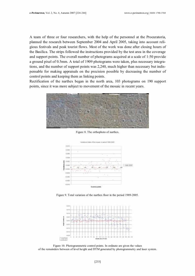
Rectification of the narthex began in the north area, 103 photograms on 190 support
points, since it was more subject to movement of the mosaic in recent years.
Figure 8. The orthophoto of narthex.
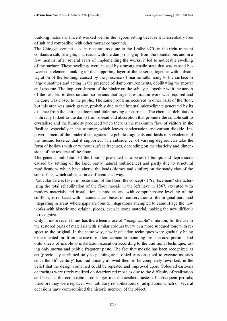
Figure 9. Total variation of the narthex floor in the period 1989-2005.
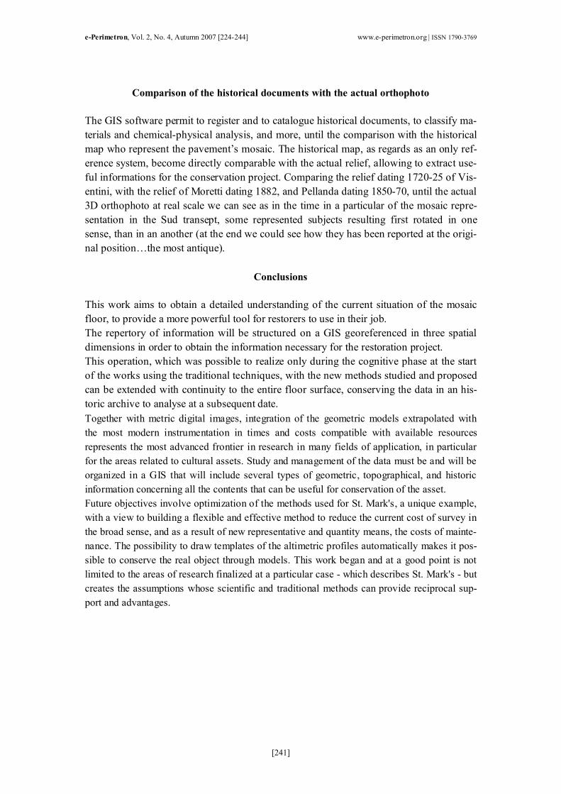
Figure 10. Photogrammetric control points. In ordinate are given the values
of the remainders between of level height and DTM generated by photogrammetry and laser system.

e-Perimetron, Vol. 2, No. 4, Autumn 2007 [224-244] www.e-perimetron.org | ISSN 1790-3769
[234]
Figure 11. DTM generated by Leica HDS 3000.
The images were handled using the updated Socet Set 5.2.0 software by BAE Systems
and Bingo and viewing with the ArcGis and Arclnfo suite.
Figure 12. Comparison between the level height of the 2005 and extracted height
from the data laser scanner (historical points).
Figure 13. Comparison between the level height of the photogrammetric check points
and the extracted height from the lattice (generated from the data laser scanner).

e-Perimetron, Vol. 2, No. 4, Autumn 2007 [224-244] www.e-perimetron.org | ISSN 1790-3769
[235]
Figure 14. Comparison between the level height of the photogrammetric check points
and the extracted height from the photogrammetric DTM (generated by automatic image matching).
The boundaries between the floor and risers that appear in the perimeter models at the
walls, columns and otherwise must be accurately determined. This is done by observing
the models through a stereoscope and marking off the space where the points should be
that form the DTM and the 3D orthophoto.
Figure 15. 3D model of the floor generated by automatic image matching (Z factor = 3x).
Figure 16. 3D model of the floor generated by lattice with laser scanner system (Z factor = 3x).

e-Perimetron, Vol. 2, No. 4, Autumn 2007 [224-244] www.e-perimetron.org | ISSN 1790-3769
[236]
Figure 17. Raster calculator from ArcInfo: the image represents the difference between the DTM photogrammetric and laser.
A Leica HDS 3000 laser scanner was used in the narthex to compare with DTM from
automatic image matching and to have the risers. The intention is to obtain a realistic and
precise representation of the entire floor inside the Basilica, represented by a model in
elevation consistent with the floor and the sections at the 1:50 scale.
Organization of a GIS of the survey
The historic and artistic wealth of the St. Mark's Basilica call for tools suitable to compar-
ing the information contained in them. All the iconographic documents, written records,
studies and investigations made to expand the understanding of the Basilica represent an
enormous body of information which leads to the need to analyze, interpret and correlate
this data. This information is difficult to manage unless it is organized into a GIS. A GIS
is a virtual archive, easily accessible and referenced, where all the material available can
be managed and used by restorers, structural engineers, historians, critics, chemists, etc.
This means, for example, visualizing the 3D orthophoto on the floor of the Basilica and,
selecting a portion of it, laying out the numerous types of information in addition to the
image of it conditions at actual scale, including a description of the historic iconography,
material composition, any restoration interventions done, the description of the execution
techniques used, and more. The system can also access interesting information for the his-
tory and life of St. Mark's by linking up with other archives through the web and expand-
ing the boundaries of knowledge aimed mainly through various channels of communica-
tion.
For many years, the Procuratoria of San Marco has been gradually converting all of its
documents and archives into a digital format in order to obtain a data base that would
support and facilitate the work of scientists and scholars. Still, as the surveys have be-
come available and technological progress has advanced hardware and software, com-
puter models are being built that acquire and control the data and can flexibly and imme-
diately incorporate, elaborate and represent the information required by the job.
Approximately 5,000 written documents and iconographs that make up the historic ar-
chives of the works in the Basilica have already been added to the computer archives.
There are also photogrammetric surveys of the building rectified in numeric format, plan
and altimetric sections, digital altimetric models of the floor (DTM) and control of its

e-Perimetron, Vol. 2, No. 4, Autumn 2007 [224-244] www.e-perimetron.org | ISSN 1790-3769
[237]
movements, obtained from high precision levelling. In recent years, the studies of mathe-
matical models of the structural stresses with 3D graphic presentation were added to the
altimetric progress of the mosaic floor and other architectonic elements, as one of the five
main domes, elevations, layouts and sections in numeric form to the nominal scale of 1:50
and for the most 3D digital orthophoto.
Figure 18. Test zone, reverse engineering of the mosaic. DTM generate by automatic image matching.
Figure 19. Test zone, 3D real model.
Figure 20. Registration of clouds laser scanner.

e-Perimetron, Vol. 2, No. 4, Autumn 2007 [224-244] www.e-perimetron.org | ISSN 1790-3769
[238]
The GIS is useful for protecting, engineering and job site management through several
phases developed according to the knowledge acquired and which lead to simulation
models for prevention and "scheduled" maintenance.
The phases can have several levels, such as geographic cataloguing and storing the docu-
ment sources relating to the area object of study from an historic perspective and a chemi-
cal and physical perspective; to provide support to the restoration project by extracting
information linked to quality aspects (radiometric knowledge of the surface object of res-
toration, identification of surface deterioration phenomena, etc) and metric aspects. In
particular, this form automatically extracts the templates of the altimetric profiles to use
in the subsequent phase of repositioning the tesserae on the recomposed floor in its actual
progression to represent the basis for processing provisional models relating to the states
of risk and future interventions.
The state of development of the GIS is considered an open system, namely, the hypothe-
sized structure must be applied to real during the concrete restoration work in progress, in
addition to representing the information archives of the knowledge on the parts and whole
of the Basilica, including their relation to the surroundings.
The causes of the deterioration, conservation and restoration of the mosaic layer
The Procuratoria of San Marco has always been steadfast in defining a diagnostic picture
that is broad and extensive enough to formulate concrete hypotheses on the main causes
and mechanisms of deterioration of the components, the Basilica, and therefore, provide
useful information in order to optimize the conservation and use of the building, which
demonstrates and has always demonstrated very complex conservation problems. For ex-
ample, the conditions of decay of the mosaic floor is clear even from a completely super-
ficial observation, despite the constant and recurring maintenance works (restoration and
partial rehabilitation) by specialized experts of the Procuratoria and who attempt to pre-
serve vast portions from the wear and tear of tourist traffic by putting up physical barriers
(metal rails, mandatory routes, floor coverings).
These factors are augmented by "contingent" factors which are added to the aspects re-
lated to the specific environmental conditions caused by the lagoon setting, namely,
flooding, salts, nitrogen oxide, and nitrogen dioxide (due to vehicle traffic in the canals),
hydrogen sulphide (which is formed by fermentation of the algae), which contribute to
aggravating and making the problem of protection more complex.
One example is the part of the mosaic in the test zone. In this area, there are several swol-
len areas on the mosaic surface caused by insertion of Chioggia cement in the mortar mix-
ture used to bind the tesserae. In nearly the entirety of the pavement, the first supporting
sublayer is made up of aerated lime, sand and pottery shards that represents the mortar
historically used in the Basilica, slightly different due to the brick dust and frequently
used as a binder. Only the areas subjected to 19th-century restoration displayed a cement
subfloor or the use of Portland cement, which was added to give better hold to the mortar.
The proto of the Basilica, Pietro Saccardo, introduced the practice of conservational resto-
ration in the Basilica in the late 1800s and opposed replacements made during traditional
restorations, arguing the importance of using cement as an important technological ad-
vancement. He used it several times and considered it a real revolution in the field of
e-Perimetron, Vol. 2, No. 4, Autumn 2007 [224-244] www.e-perimetron.org | ISSN 1790-3769
[239]
building materials, since it worked well in the lagoon setting because it is essentially free
of salt and compatible with other mortar compounds.
The Chioggia cement used in restorations done in the 1960s/1970s in the right transept
contains a salt, stringite, that reacts with the damp rising up from the foundations and in a
few months, after several years of implementing the works, it led to noticeable swelling
of the surface. These swellings were caused by a strong tensile state that was caused be-
tween the elements making up the supporting layer of the tesserae, together with a disin-
tegration of the binding, caused by the presence of marine salts rising to the surface in
large quantities and acting in the presence of damp environments, debilitating the mortar
and tesserae. The impoverishment of the binder on the sublayer, together with the action
of the salt, led to deterioration so serious that urgent restoration work was required and
the zone was closed to the public. The same problems occurred in other parts of the floor,
but this area was much graver, probably due to the internal microclimate generated by its
distance from the entrance doors and little moving air currents. The chemical debilitation
is directly linked to the damp from spread and absorption that promote the soluble salt to
crystallize and the humidity produced when there is the maximum flow of visitors in the
Basilica, especially in the summer, which leaves condensation and carbon dioxide. Im-
poverishment of the binder disintegrates the pebble fragments and leads to subsidence of
the mosaic tesserae that it supported. The subsidence, of varying degree, can take the
form of hollows with or without surface fractures, depending on the elasticity and dimen-
sions of the tesserae of the floor.
The general undulation of the floor is presented as a series of bumps and depressions
caused by settling of the land: partly natural (subsidence) and partly due to structural
modifications which have altered the loads (domes and similar) on the sandy clay of the
subsurface, which subsided in a differentiated way.
Particular care is taken in restoration of the floor: the concept of "replacement" character-
izing the total rehabilitation of the floor mosaic in the left nave in 1867, executed with
modern materials and installation techniques and with comprehensive levelling of the
subfloor, is replaced with "maintenance" based on conservation of the original parts and
integrating in areas where gaps are found. Integrations attempted to camouflage the new
works with historic and original pieces, even in stone material, making the new difficult
to recognize.
Only in more recent times has there been a use of “recognizable” imitation, for the use in
the restored parts of materials with similar colours but with a more subdued tone with re-
spect to the original. In the same way, new installation techniques were gradually being
experimented on: from the use of modern cement to mounting prefabricated portions laid
onto sheets of marble to installation execution according to the traditional technique, us-
ing only mortar and pebble fragment paste. The fact that mosaic has been recognized as
art (previously attributed only to painting and copied cartoons used to execute mosaics
since the 16th century) has traditionally allowed them to be completely reworked, in the
belief that the design contained could be repeated and improved upon. Coloured cartoons
or tracings were rarely realized on deteriorated mosaics due to the difficulty of realization
and because the compositions no longer met the aesthetic tastes of subsequent periods;
therefore they were replaced with arbitrary rehabilitations or adaptations which on several
occasions have compromised the historic memory of the object.

e-Perimetron, Vol. 2, No. 4, Autumn 2007 [224-244] www.e-perimetron.org | ISSN 1790-3769
[240]
The "reverse" procedure in use for some time involves laying the tesserae of the composi-
tion of the figures on top of movable supports and works with fairly small portions of mo-
saic, easier to transport and handle. Once the work of cleaning and restoration of the mo-
saic is concluded, the pieces are gathered together to lay them on the ground. The method
consists of bonding the mosaic on sheets of paper with a reverse coloured image of the
portion involved so that the faces of tesserae are bonded to the support with a vegetable
glue and the other side, a truncated pyramid, faces upward. Subsequently, the composi-
tion is transferred onto the mortar spread out in an area to decorate and it is left to dry.
After the glue sets, paper is removed and the surface of the tesserae is cleaned of any glue
residue.
Figure 21. Construction of the model 3D, generated by the data laser, particular.
The original design is taken with a photograph of which the negative is used, printed on
special material. The procedure used by the engineers of the Basilica to rectify the photo-
graph of the floor at actual scale is not suitable for representing the characteristic undula-
tion of the floor, while the 3D orthophoto is. A level of detail never reached previously
and a cognitive instrument are achieved that can be immediately used in protection, engi-
neering and site management. In the test area, a 3D orthophoto was used for restoration of
the mosaics as direct support of the work of the mosaicists, which work daily on mainte-
nance and conservation of the mosaic heritage.
The digital orthophoto at a 1:1 scale establishes the disposition of the tesserae starting
with photographic images in which the metric information is associated with the visual
information and all is inserted into a GIS.
The immediate application of the orthophoto results from its digital format, thanks to
which all the portions of the floor in which it was divided in the design phase of the resto-
ration up until definition of the mosaic tesserae. As mentioned, once there is a 3D model,
it is also possible to automatically extract the sections that are representative of the undu-
lating progression of the floor and which can be used to make the templates for the mo-
saicists to take note of the quotas in restoring the subfloor.
e-Perimetron, Vol. 2, No. 4, Autumn 2007 [224-244] www.e-perimetron.org | ISSN 1790-3769
[241]
Comparison of the historical documents with the actual orthophoto
The GIS software permit to register and to catalogue historical documents, to classify ma-
terials and chemical-physical analysis, and more, until the comparison with the historical
map who represent the pavement’s mosaic. The historical map, as regards as an only ref-
erence system, become directly comparable with the actual relief, allowing to extract use-
ful informations for the conservation project. Comparing the relief dating 1720-25 of Vis-
entini, with the relief of Moretti dating 1882, and Pellanda dating 1850-70, until the actual
3D orthophoto at real scale we can see as in the time in a particular of the mosaic repre-
sentation in the Sud transept, some represented subjects resulting first rotated in one
sense, than in an another (at the end we could see how they has been reported at the origi-
nal position…the most antique).
Conclusions
This work aims to obtain a detailed understanding of the current situation of the mosaic
floor, to provide a more powerful tool for restorers to use in their job.
The repertory of information will be structured on a GIS georeferenced in three spatial
dimensions in order to obtain the information necessary for the restoration project.
This operation, which was possible to realize only during the cognitive phase at the start
of the works using the traditional techniques, with the new methods studied and proposed
can be extended with continuity to the entire floor surface, conserving the data in an his-
toric archive to analyse at a subsequent date.
Together with metric digital images, integration of the geometric models extrapolated with
the most modern instrumentation in times and costs compatible with available resources
represents the most advanced frontier in research in many fields of application, in particular
for the areas related to cultural assets. Study and management of the data must be and will be
organized in a GIS that will include several types of geometric, topographical, and historic
information concerning all the contents that can be useful for conservation of the asset.
Future objectives involve optimization of the methods used for St. Mark's, a unique example,
with a view to building a flexible and effective method to reduce the current cost of survey in
the broad sense, and as a result of new representative and quantity means, the costs of mainte-
nance. The possibility to draw templates of the altimetric profiles automatically makes it pos-
sible to conserve the real object through models. This work began and at a good point is not
limited to the areas of research finalized at a particular case - which describes St. Mark's - but
creates the assumptions whose scientific and traditional methods can provide reciprocal sup-
port and advantages.

e-Perimetron, Vol. 2, No. 4, Autumn 2007 [224-244] www.e-perimetron.org | ISSN 1790-3769
[242]
Figure 22. Drawing of the old mosaic floor of St. Mark's, work of Moretti 1882.
Figure 23. Drawing of the old mosaic floor of St. Mark's, work of Pellanda 1850-70.

e-Perimetron, Vol. 2, No. 4, Autumn 2007 [224-244] www.e-perimetron.org | ISSN 1790-3769
[243]
Figure 24. Comparison of the historical documents with the actual orthophoto.

e-Perimetron, Vol. 2, No. 4, Autumn 2007 [224-244] www.e-perimetron.org | ISSN 1790-3769
[244]
Figure 25. Comparison of the historical documents with the actual orthophoto (particular).
References
Monti, C., Achille, C., Brumana, R., Fregonese, L. & Savi, C. (2002). 3D models genera-
tion from laser scanner data to support digital orthophoto 3D: the mosaic surface of the
floor of S. Marcus Basilica in Venice, Commission V Symposium, Proceedings ISPRS
WG V/4 — Close-range imaging, Long-range vision, Corfù Greece, pp.423-428.
Vio, E. (2001). Lo studio della basilica di San Marco attraverso nuove rappresentazioni,
in I nuovi metodi d’indagine e comunicazione della storia dell’architettura, pp. 115-120.
Milan, Italy: Sinai publishers.
Vio, E. & Lepschy, A. (1999). Science and Technique of restoration of the St. Mark’s Ba-
silica, Proceedings of the international symposium of studies of Venice (16-19 May
1995). Venice, Italy: Istituto veneto di scienze, lettere ed arti.
Achille, C., Brumana, R., Fregonese, L., Monti, G., Monti, C., Savi, C., Vio, E. (2002). Il
pavimento musivo della Basilica di San Marco. L ‘ortofoto 3D alla scala 1:1 come
palinsesto virtuale di un sistema informativo, ASITA, Proceedings of the 6th National
Conference on Geomatics for the Environment, Territory and Cultural Heritage, Perugia,
Italy, pp. 29-34.