complete machining has never been easier
TRANSCRIPT

Ausgabe 2 | ?? Monat ?? 2015 | siemens.de
Das Magazin für die Werkstatt
Issue 2 | September 2015 | siemens.com/cnc4you
Practical knowledge for the shopfloor
Complete machining has never been easierNew functions for multi-tasking machines
Digitalization for the shopfloor
Tailor-made portfolio for small and medium-sized businesses
Logging made easy
Sinumerik high-level programming language: The WRITE command

CNC4YOU 2/2015 | Contents
Cover photo: Siemens AG
On the shopfloor
News
26 eBooklet for EMO 2015 / EMO trade fair show — smart operation
27 Successful spindle workshop / New learning factory with Sinumerik
04 Complete machining has never been easierNew functions for operating and programming multi-tasking machines
07 Top-level Sinumerik training TAC for machine tools in Piacenza
08 Digitalization for the shopfloorTailor-made portfolio for small and medium-sized businesses
10 Improved usabilityNew functions for Sinumerik Operate
12 Working efficiently with two toolsFour-axis turning with Sinumerik
14 Economic efficiency as a success factorThe right spindle drive for the machine tool
EMO
Tips & tricks
Education
PublisherSiemens AGDivision Digital FactoryGleiwitzer Straße 555,D-90475 Nürnbergsiemens.com/digital-factory
Division Digital FactoryCEO Anton S. Huber
Editorial responsibility in accordance with the German press lawBernd Heuchemer
Responsible for technical contentHans Pischulti
Editorial committee chairsKarsten Schwarz, Andreas Grözinger
Publishing housePublicis Pixelpark Erlangen
P.O. Box 32 40, 91050 Erlangen, Germany
Editor: Gabriele Stadlbauer
Copy Editor: Julia Robinson
Layout: Michael Schrödel
DTP: TV Satzstudio, Emskirchen
Print: Wünsch Offset-Druck GmbH, Neumarkt/Opf.
Article No.: E20001-A1840-P610-X-7600
Circulation: 9,000
© 2015 by Siemens Aktiengesellschaft Munich and Berlin All rights reserved.
This issue was printed on paper made from environmentally friendly chlorine-free bleached pulp.
The following products are registered trademarks of Siemens AG:
SHOPMILL, ShopTurn, SINAMICS, SINUMERIK, SINUMERIK 828, SINUMERIK 840, SINUTRAIN
If trademarks, trade names, technical solutions, etc., are not referred to specifically, it does not mean that they are not protected. The information in this journal only includes general descriptions and/or performance characteristics, which do not always apply in the form described in a specific application, or which may change as products are developed. The required performance characteristics are only binding if they are expressly agreed at the point of conclusion of the contract.
18 Control improves productivityOptimal machine monitoring with ncTOUCH
20 Dual roleTechnology and financing expertise from a single source
22 Logging made easy Sinumerik high-level programming language: The WRITE command
24 Teaching and practice — hand in hand Trier University of Applied Sciences teaches students using Sinumerik CNC and NX software
Students at Trier University of Applied Sciences are trained using modern machine tools equipped with Sinumerik 840D sl
Siem
ens
AG
24
The new Version 4.7 of the Sinumerik Operate software significantly simplifies the programming and operation of multi-tasking machines
Siem
ens
AG
4
South African CNC machine tool supplier W.D. Hearn has installed ncTOUCH software as a standard feature on all Leadwell CNC machines with Sinumerik 828D
Siem
ens
AG
18

Editorial | CNC4YOU 2/2015
3
Dear readers,
Siem
ens
AG
Claudio JansApplications EngineerSiemens Technology and Applications Center (TAC)
The focus of this year’s EMO in Milan is the ongoing digitalization of the machine tool
world. Digital technology, such as networked machines, innovative operating concepts and
mobile devices, allows production workflows to be optimized. With smart operation,
Siemens demonstrates that digitalization and integrated production can be an ideal solution,
even for shopfloor applications. Thanks to computer-based work preparation, paperless
production, and the ability to call up current machine statuses on a smartphone or tablet,
even small companies can make their production more flexible and efficient.
In Milan we will also be presenting our enhanced Sinumerik hardware and software,
which facilitates even greater productivity in turning, milling, grinding and five-axis milling.
The improved operating concepts in Sinumerik Operate, for example, make operation on
the control system even easier and safer than before. And, with innovative cycle functions,
workpieces can be machined even more quickly and precisely.
Sinumerik Operate has also been enhanced with user-friendly functions for complete
machining. As all functions for milling and turning are now integrated in a single system,
even turning on a milling machine is easier than ever before. Visitors to the Siemens booth
at EMO can see for themselves the advantages of multi-tasking machining live on a
five-axis machine from the Italian manufacturer MCM.
Visit us at our booth in Hall 3 at EMO and find out about all the new Sinumerik
developments. It will be worth your while!

4
Multi-tasking machines are capable of imple-menting multiple production technologies, such as turning, milling, drilling and measuring,
thus enabling the complete machining of workpieces in a single clamping. Repeated reclamping becomes a thing of the past and the efficiency and precision of production are increased. The Sinumerik 840D sl CNC has already integrated all the functions required for sophisticated complete machining: a milling spectrum from high-performance machining centers for powertrain production in the automotive industry to highly dynamic five-axis machining centers for mold construction in the aerospace industry. The turning spectrum ranges from multi-channel five-axis turning centers with b-axes to high-performance multi-spindle applications.
Closing the gap in the multi-tasking segment
Multi-tasking machine operators are expected to be able to both program and operate all the production processes available on their machines. However, the
traditional training for cutting machine operators usually concentrates on a technology-specific field, such as turning or milling. The new Version 4.7 software of the user interface Sinumerik Operate closes this gap. The intuitive cross-technology oper-ation and programming make all the multi-tasking machine’s machining processes available to spe-cialist staff. With the new functions in Version 4.7 of the software, the user can take advantage of the high productivity of complete machining in pro-duction — even for shopfloor-oriented production, in conjunction with job shop programming.
User-friendly — from set-up to tool management
With the new Sinumerik Operate, the turning func-tions for milling and the milling functions for turning are perfectly combined in a single interface. The turning and milling tools and the turning and milling cycles are automatically adjusted to suit the given form of machining and respective machining plane. The tool lengths are also taken into account and displayed accordingly. One extremely practical enhancement is that complete turning functionality is now also available in ShopMill.
The intelligent JOG mode in Sinumerik Operate provides graphical, interactive support to users set-ting up turning machines and turn-milling machines. A tool can therefore be loaded easily by pressing just three buttons. In addition to the existing option to choose between technologies such as face milling or chip removal, there are now new functions for multi-tasking machines. Unproductive time is thus reduced to an absolute minimum. In addition, optimum sup-port is provided for tool measurement in JOG mode. In the new function for multi-tasking machines, a measurement function for turning tools is available, which makes it possible to measure turning tools while they are engaged. The mask changes depending
Complete machining has never been easier
Siemens is significantly simplifying the operation and programming of multi-tasking machines. The new software, Version 4.7, of the user interface Sinumerik Operate standardizes the look and feel of machining across a range of technologies. This makes it easier for machine operators to switch between turning and milling machines and provides direct, intuitive access to complex complete machining processes.
New functions for operating and programming multi-tasking machines
CNC4YOU 2/2015 | EMO

5
on the tool type to be measured. In JOG mode, the TSM area has also been expanded to include the posi-tioning of turning tools. Once the user selects a turning tool, the machine is switched to turning mode.
Another highlight of Sinumerik Operate is the clearly arranged Sinumerik tool management. To facilitate efficient management of tool data in com-plete machining, the functionality has been expanded so that users can view the tool and magazine data for milling and turning tools, including all the details, in a single image. Input is performed simply by means of parameters. The turning tools are presented as icons, and complex tools such as multi-tools are sup-ported, thus significantly simplifying operation for the user.
Expanded cycle functions for perfect results
By using innovative cycles that perform exception-ally well in multi-tasking machines thanks to their standardized usability, comprehensive work steps in complex machining operations can be resolved more easily. The Cycle800 swivel cycle, for example, is also easy to operate and understand when combining turning and milling technologies. With the aid of swivel heads or swivel tables, this cycle can be used to machine and set up inclined planes — both man-ually and automatically.
In addition, turning cycles have been expanded in programGUIDE to facilitate easy operation of com-plex multi-tasking machines. A graphical contour cal-culator helps the user with input, and parameteriza-tion is performed easily via a dialog. Engaged tools can be graphically and interactively programmed with ShopTurn and the b-axis. During this operation,
the setting angle of the b-axis (β) and the positioning angle of the tool spindle (γ) are indicated directly in the technology area of the cycle. Milling operations on turning machines are also possible with ShopTurn and the b-axis. Machining operations on the face or lateral surface are defined by selecting the plane in the cycle, while milling on swiveled planes is per-formed with the Cycle800 swivel cycle. All milling
Siem
ens
AG
The positioning of the turning tool is
shown as an option on the screen for the
active turning tool selected
The Cycle800 swivel cycle
perfectly combines turning and milling
technologies in a single interface
Siem
ens
AG
Si
emen
s A
G

6
cycles on the turning machine are identical to those in ShopMill. Alternatively, the user can perform milling operations with programGUIDE and the b-axis. To do this, Cycle800 is selected with the “swivel plane” function, for example, and a new machining plane is generated, on which all milling functions can be created, also with the help of cycles.
The Sinumerik’s Cycle952 contour machining cycle now allows for four-axis stock removal on multi-channel turning machines. Powerful functions facil-itate workpiece machining. For example, automatic residual material detection ensures optimum cut segmentation, and automatic feed interruption guar-antees that the chip breaks evenly and can thus be precisely removed. As an optional addition, the inter-polation turning cycle is available for longitudinally or transversely machining corners on inner or outer contours.
Sinumerik also features powerful functions for five-axis machining that considerably simplify the entire process of multi-axis programming and machining, such as TRAORI tool-center-point pro-gramming, orientation smoothing while milling with ORISON, or the 3D tool radius compensation CUT3DC — CUT3DF.
Process reliability through simulation
Virtually checking production processes before machining helps prevent errors and optimizes machining times. Whether on face and lateral sur-faces, on swiveled workpiece planes or when machining in multiple machining channels, the sim-ulation demonstrates the complete machining of the workpiece. In multi-tasking machines, milling and turning technologies as well as workpiece mea-surement can be simulated simultaneously. At the same time, a 3D removal simulation is also possible for workpieces with inclined surfaces (3+2-axis machining) or free-form surfaces (3-5-axis machining). If milling machines have multiple rotary axes that can be used as spindles for turning, the clamping parameter ensures the correct orientation of the blank and alignment with the simulation. In addition, the mold-making quick view facilitates rapid simu-lation of programs with free-form surfaces. The sets G0, G1, G2, G3, BSPLINE and POLY are sup-ported, as is the display of vectors for five-axis machining — for both rotary axis programming and vector programming.
State-of-the-art technology
All combinations of the most frequently used pro-duction technologies in industry, namely turning, milling, drilling and measuring, are consistently and universally implemented in accordance with the latest technical standards in Sinumerik Operate, both in programming and in operating. A variety of additional technologies, such as grinding, eroding, laser and water-jet cutting, nibbling, honing, slot-ting, and so on, are also supported. The openness of Sinumerik 840D sl allows these designated pro-duction technologies to be integrated into a multi-tasking application, thus increasing efficiency of production.
All milling cycles on the turning machine are identical to those in ShopMill
Cycle952 now also allows for four-axis chip removal on multi-channel turning machines
3D removal simulation is also possible for workpieces with inclined surfaces
Siem
ens
AG
Si
emen
s A
G
Siem
ens
AG
INFO AND CONTACT
siemens.com/[email protected]
CNC4YOU 2/2015 | EMO

7
TAC for machine tools in Piacenza
Top-level Sinumerik trainingAt the Technology and Application Center (TAC) in Piacenza, instructors are given in-depth training on Sinumerik. In this way, Siemens supports the training at vocational colleges and universities while also providing training sessions for machine manufacturers and dealers. This helps secure the future of the Italian mechanical engineering and manufacturing industries.
The TAC Italy was established in 2011 in Piacenza. Its mission was clearly defined: to train instructors
with the aim of disseminating practical knowledge and establishing Siemens’ CNCs in training and production, to communicate technical innovations, and to serve as a point of contact in the region. These aspects are becoming in-creasingly important, particularly in view of the digitalization of the ma-chine tools industry. The TAC also has plans to set up a training and further education network that will work with technical institutions, educational es-tablishments, vocational schools and universities.
From the very start, the TAC’s coop-eration with universities has been ex-tremely effective. The University of Ap-plied Sciences in Milan, for example, has been offering a single-semester mechanical engineering course at the TAC since 2011, and the University of Applied Sciences in Turin also collabo-rates with the TAC in Piacenza. In terms
of equipment and facilities, the TAC of-fers optimum conditions for efficient Sinumerik training. An area covering 700 m² in total contains two training rooms, a large machine shop with a conference room, six machine tools, one robot, and training simulators for the latest Sinumerik and Sinamics prod-ucts. Machine manufacturers, users and educational providers are making use of the offerings at TAC Piacenza; in-deed, more than 600 participants have been trained there already this year. Thanks to the support of various tech-nology partners, the center is able to provide a practical demonstration of the complete range of CNC applications with the six machine tools.
The close collaboration between the certified training partners Istituto Pro-fessionale LBS, CNOSFAP, CNOSFAP Bearzi, Assocam Scuola Camerana and Istituto San Gaetano helps ensure sus-tainable and constantly up-to-date knowledge transfer in CNC training in Italy.
INFO AND CONTACT
siemens.com/[email protected]
> Castrol Industrial
> Coord3
> Hoffmann Group Italia S.p.A.
> Kuka Roboter Italia S.p.A.
> Project Group
> Renishaw S.p.A.
> S.A.M.U. S.r.l.
> Sequoia S.r.l.
> Speroni S.p.A.
> Vega International Tools S.p.A.
TECHNOLOGY PARTNERS
Pho
top
hill
a
Siem
ens
AG
More than 600 participants a year are trained on Sinumerik CNCs at TAC Piacenza
EMO | CNC4YOU 2/2015

8
Digitalization, or Industrie 4.0, sounds like some-thing that involves large-scale IT infrastructure and networking of extensive production facil-
ities — in short, something that requires IT expertise and substantial investments. For companies that are more shopfloor-oriented, these terms are often asso-ciated with the uncertainty of something that might be just a little too ambitious for them. But it has never been so easy to integrate a machine tool into production processes. With smart operation, Siemens enables small and medium-sized companies to ben-efit from modern modes of operation in production with minimal effort.
Simple and efficient machine operation
It begins with working on the machine. Whether milling, turning or complete machining, whether in large quantities or small batches, smartOperate pro-vides the operator with many new, extremely useful functions from Sinumerik. In conjunction with Sinumerik 840D sl, for example, the new OP 015 black and OP 019 black operator panels with multi-touch and gesture technology can be used to make operating the control system even more efficient. The user can simply zoom, rotate or move the work-piece across the screen during the simulation using gesture control, and thus check it from all angles before starting the NC program. But smartOperate also offers improved editor functions in Sinumerik Operate. Due to the color display of the program-ming commands, the user can see at a glance whether a rapid traverse or feed rate was pro-grammed. What’s more, the font size on the screen can be made larger or smaller, allowing for a more
detailed presentation. The cycle view is equally convenient as a work step, as it presents cycles in programGUIDE in exactly the same way as in ShopTurn or ShopMill.
Never lose sight of the machine
Thanks to smartMobile, the operator always knows what is going on, even when he or she is not standing at the machine. This enables the operator to access Sinumerik 840D sl and 828D with any terminal equip-ment and a standard web browser. Important infor-mation, such as the operating state, pending alarms, utilization, tool information and much more, can be displayed at a glance on any PC, tablet or smart-phone, for example, enabling rapid intervention in the event of disruptions in production.
What is especially practical is that smartMobile provides executable templates that allow the user to
Digitalization for the shopfloorDigitalization has become an essential undertaking in the manufacturing industry, because integrated production increases efficiency and thus competitiveness. With smart operation, shopfloor-oriented companies can now share in the vision of digitalization — in a way that precisely suits their requirements.
Tailor-made portfolio for small and medium-sized businesses
> smartOperate: new operating modes with touch technology
> smartMobile: job status and other informa-tion, available via mobile devices
> smartPrepare: work preparation with SinuTrain
> smartIT: all documents for a job on the machine
SMART OPERATION AT A GLANCE
smartPrepare
CNC4YOU 2/2015 | EMO

9
access a great deal of relevant information. These best-practice templates were developed and designed in collaboration with users.
Increased productivity thanks to work preparation
Achieving ever-higher levels of productivity is also necessary in the machine shop sector. With smartPrepare, the next workpiece can be pro-grammed even while the machine is still in use. While the machine is in the process of producing one job, the machine operator can use a SinuTrain station to quickly and easily prepare the next part. With its original Sinumerik CNC kernel, SinuTrain behaves identically on a PC to the Sinumerik CNC, and is therefore ideal not only for professional training but also for reliable offline programming. Several example machines are already preconfigured in the SinuTrain software. And if these examples are not enough, the machine supplier can adapt SinuTrain to the characteristics of the actual machine.
Paperless production is a reality
The only question that remains is how to get the gen-erated data onto the machine. By USB or another storage medium? With the aid of a paper printout? It can now be done much more easily and reliably. With
INFO AND CONTACT
siemens.com/[email protected]
smartIT, all the order documentation, such as parts programs, DXF drawings and images, is available on the control panel via the network connection. This means there is no longer any need to search for doc-uments. With the EES (Execution from External Storage) function in Sinumerik Operate, any media outside Sinumerik can be accessed in order to display these order documents on Sinumerik or to process them directly. The size and quantity of parts, pro-grams and production data are, therefore, no longer limited by Sinumerik’s internal memory; they are vir-tually unlimited thanks to the use of external memory.
Another important feature for paperless produc-tion is the new DXF reader option. If the contour or the positions for drilling patterns no longer need to be programmed entirely on the CNC, and if the data can instead be transferred thanks to the CAD reader, this saves up to 90% of the programming time. DXF files can be opened directly on the CNC and transferred into the CNC program at the click of a mouse.
smartOperate
smartPrepare
smartIT
smartMobile
Siem
ens
AG
EMO | CNC4YOU 2/2015

10
measurement. The standard logs are created using HMI support screens that are integrated in the measuring cycle support in the “Program” operating area. When measuring in both JOG and the measuring cycles, the user can ex-port the logs in either text or tabular format. The logs can be stored on external media such as a local drive, USB or network, as well as in the parts program.
Improved usabilityNew functions for Sinumerik Operate
Sinumerik Operate offers functions that let the operator visualize measurement when setting up a
workpiece. From software Version 4.7, measurement results can now also be logged. Logging these in JOG simply re-quires pressing the “measurement log” soft key, which appears at the end of the measuring process. A standard log is then generated automatically, con-taining the measurement results of the
most recently executed measurement variant. However, the user can also sim-ply log the results from measurement cycle functions of automatic programs without any NC writing involved. To do this, the new standard log function must be selected by programming a cycle call-up. Four log types are avail-able: calibrate workpiece measuring probe, calibrate tool measuring probe, tool measurement, and workpiece
Sinumerik Operate, the operating and programming interface for machine tools, has been expanded to include new functions in Version 4.7. Setting the workpiece, programming and program management have been made even more convenient for the user.
Sie
men
s A
G
Logging in JOG
The following settings are possible on the screen:
> Log format: “text format” *.txt / “tabular format” *.csv
> Log data: “new / add”
> Log storage: “directory” (incl. select directory)
> Log file name: *.txt or *.csv
Editor — new functions
Colored highlighting of NC functions:
> Comments (gray)
> NC sets / functions (black)
> Tool call-up / speed… (blue)
CNC4YOU 2/2015 | EMO
11
For measurements in automatic mode, Sinumerik Operate provides ef-ficient measuring cycles for any appli-cation. In the new software version, the function “align 3D probe in mea-surement direction” is now also avail-able, allowing for more precise mea-surement results in case higher preci-sion is required.
Clear programming, more storage space
In Sinumerik Operate, a suitable pro-gramming method is available for every area of application — whether ShopMill, ShopTurn or programGUIDE. With the new functions, working with editors is now even more convenient. For better readability of NC programs, the NC func-tions are highlighted in color in the edi-tor. In the settings screen, the user can define the font size, line breaks and even the cycle presentation on a scal-able basis. What’s more, when arranging large programs into blocks, the operator
can now view the blocks on two levels — for even more clarity on the screen. Scalable cycles allow for quick program-ming in ShopMill and programGUIDE, whereby the user can switch between a complete view and a simplified paramet-ric representation. The new EES (Execu-tion from External Storage) function en-sures consistent and simplified program handling: the NC and local drive there-fore merge into one, and there is only one program memory. The benefit for the operator: “Extcall,” with the com-plete path details, is dropped completely, although old programs with “Extcall” will continue to function.
A particular highlight is the added option to also import CAD files directly into the programming in the “program-ming with the DXF reader” operating area. A Drawing eXchange Format (DXF) file is read in, and contours or drill points are filtered out of it. These are implemented in such a way that they can be understood by the geome-try processor or the cycle support in
Sinumerik Operate. DXF files gener-ated in a CAD system can be opened di-rectly in the control system, and con-tours and points can be extracted at the click of a mouse and then saved as a Sinumerik program. Alternatively, the files can be saved on a network or USB and opened from there like an NC program via the file management sys-tem. Last but not least, the user mem-ory in the program management area has been enlarged — from a 2-GB to a 6-GB CompactFlash (CF) memory card — and now offers direct access to user and manufacturer cycles.
Editor — new functions
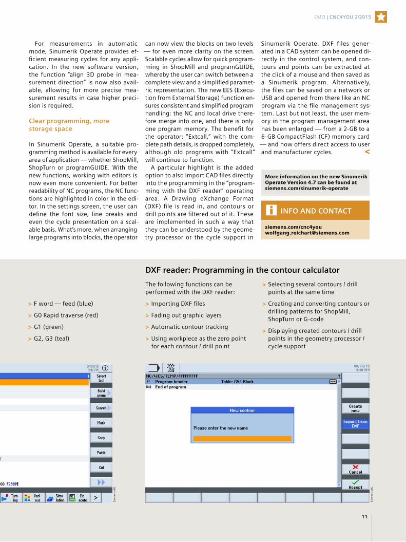
> F word — feed (blue)
> G0 Rapid traverse (red)
> G1 (green)
> G2, G3 (teal)
DXF reader: Programming in the contour calculator
The following functions can be performed with the DXF reader:
> Importing DXF files
> Fading out graphic layers
> Automatic contour tracking
> Using workpiece as the zero point for each contour / drill point
> Selecting several contours / drill points at the same time
> Creating and converting contours or drilling patterns for ShopMill, ShopTurn or G-code
> Displaying created contours / drill points in the geometry processor / cycle support
More information on the new Sinumerik Operate Version 4.7 can be found atsiemens.com/sinumerik-operate
INFO AND CONTACT
siemens.com/[email protected]
Sie
men
s A
G
Sie
men
s A
G
EMO | CNC4YOU 2/2015

12
Four-axis turning with Sinumerik
The prerequisite for four-axis turn-ing, also known as balance cutting, is a turning machine with at least
two independent tool carriers. As a rule, this involves one tool turret behind the rotation center and a second in front of the rotation center. The machine has to be designed in such a way that both
Tangible productivity advantages — that’s what users gain from machining on the same machining profile simultaneously with two turning tools. Modern CNC controls make it possible to program this highly sophisticated machining task directly on the machine without the need for a CAD/CAM system.
Working efficiently with two tools
In this respect, four-axis chip removal can be considered a special form of multi-channel machining: simultane-ous machining with two identical tools (for example two 80-degree roughing inserts) on one machining profile of the workpiece. Balance cutting offers two significant advantages compared with
tool carriers can be engaged on one workpiece simultaneously — one on the main spindle and one on the counter spindle. If both tool carriers are moved independently, two indepen-dent CNC programs are executed simul-taneously, thus activating a multi-chan-nel structure in the CNC control system.
Siem
ens
AG
/ Pu
blic
isPi
xelp
ark
In addition to an increase in chip volume, with an even cutting insert load, balance cutting (right) serves to balance out the cutting forces on thin or long workpieces
Cutting forcesCutting forces
Cutting forces
Vibration
CNC4YOU 2/2015 | EMO

13
machining using only one cutting in-sert: First, when machining long, thin components, the balancing of the cut-ting forces increases the dimensional accuracy, since the use of two opposite cutting inserts eliminates the distortion of the workpiece resulting from the cutting force. Second, the cutting vol-ume per time is increased. There are two possible strategies for achieving these benefits: either synchronous or offset tool path control.
Everything in one channel
In synchronous path control, the cut-ting inserts are always exactly opposite each other. The two compound slides of the turrets therefore perform exactly the same movement in the respective x and z geometric axes. Because the cut-ting thickness is distributed equally on both cutting edges, the feed per revo-
INFO AND CONTACT
siemens.com/[email protected]
Siem
ens
AG
lution can be doubled. As a result, the chip volume per time is doubled in comparison with machining using only one cutting edge. But what happens in synchronous path control in the Sinumerik CNC? First, the activation of the tool length corrections and the ap-proach to the machining start point are carried out independently in both CNC channels. Next, the x and z axes of one channel (the following channel) are transferred to the guide channel and carried along position-synchronously. This means that the CNC sets responsi-ble for the machining are processed only in the guide channel, and the fol-lowing channel remains in the waiting position during the machining. Syn-chronous path control is equally suit-able for roughing and finishing. How-ever, to avoid measuring inaccuracies, the two cutting inserts need to have a tool radius that is as identical as possi-
ble, because the guide channel’s tool radius correction also has an effect on the second tool carrier.
Separate CNC positioning sets for each tool
In offset path guidance, the two com-pound slides carry out different move-ments. In other words, in longitudinal turning, the cutting inserts work on dif-ferent diameters, and in face turning, the cutting edges work at offset Z posi-tions. In both cases, this results in a doubling of the effective tool feed rate. Due to the path offset, however, the CNC channels have to be synchronized for each feed, resulting in brief waiting times, which is why the cutting volume per time cannot be exactly doubled compared with machining using only one tool. The offset movements of the two compound slides generally require independent CNC programs in both CNC channels. The two CNC channels are synchronized with each other only during feeds by means of WAIT marks. Because the two cutting tools work with different feeds, offset path control is suitable only for roughing.
Cross-channel CNC programming
In order to enable such complex opera-tions to also be programmed directly on the machine without a CAD/CAM system, Siemens has expanded the proven and efficient Sinumerik Cycle952 contour machining cycle: the contour and the basic cutting parameters now need only to be programmed in the guide channel. What’s more, the CNC sequences required for the respective four-axis turning strategy are created fully automatically by the contour ma-chining cycle. With just two parameters “on top,” machining with one tool can be extended into highly productive balance cutting with two tools.
Due to the equal distribution of the cutting thickness on two tools, it is possible to work at twice the feed rate with the same insert load. The chip volume per time is doubled
Siem
ens
AG
Effectively doubling the feed rate results in almost double the chip volume. Short waiting times are incurred due to the synchronization of the tools for each feed
EMO | CNC4YOU 2/2015

14
Siem
ens
AG
/ B
. Gei
ssel
bre
cht
As the heart of the machine tool, the main spindle needs to match the operational requirements as closely as possible. The characteristics required of the spindle are defined not by borderline cases but rather by the predominant machining process. Permanent-magnet motor spindles cover a very wide range of requirements and score highly thanks to their modern rotor designs in permanent-magnet synchronous motors as well as a good balance between lifecycle costs and productivity.
The right spindle drive for the machine tool
Economic efficiency as a success factor
CNC4YOU 2/2015 | EMO

15
When choosing the right spindles for the machine tool, “bigger and stronger” does not always mean “better and faster.” A
sound machine investment is possible only if the concrete requirements for the main spindle are clearly set out and aligned with the basic properties of various spindle drives. In order to determine the right type of spindle, the user must first be clear about several factors: What range of parts will be manufactured? For how many operating hours is the machine likely to be cutting per year? What speed range does the spindle need to cover? Is a high torque also required at high speeds? What maximum power is required — for continuous operation, during brief peak loads or to accelerate? Which pro-ductivity criterion is the top priority — throughput, surface quality, precision or availability? Is the pro-duction cycle characterized by long roughing phases with a consistent speed or are short clock cycles dominant, in which the ramp-up time of the spindle and the axis dynamics shape productivity? Does the spindle have to control the c-axis operation — and if so, how quick and how precise does the positioning need to be? What are the installation conditions for the machines in question? What space is available?
The machining process determines the main spindle
Clarifying these issues establishes which machining process essentially shapes the machine tool and thereby predetermines the requirements of the main spindle on the new machine. It needs to work with maximum efficiency in this machining process. This is not absolutely essential in the rather rare border-line cases, such as in brief overload operation, with reduced feed rates or with specially optimized tools.
Which spindle is suitable for what?
The most important mechanical spindle variants these days are those indirectly driven (with belt drive), those with a directly mounted motor (mounted spindles) and those with an integrated motor (motor spindles). For all spindle variants, elec-tronic speed regulation by means of a frequency con-verter is standard. The indirect spindle drive — usu-ally a belt drive — creates a good mechanical and thermal decoupling of spindle and motor. Motor vibrations are damped and transferred to the spindle, so that the spindle requires less cooling. Overall, with this drive, the requirements on the motor are lower than with directly driven spindles — especially since, as a general rule, the belt drive also constitutes a gear stage. Because the motor, spindle and belt drive form mechanically independent units, replacing components is relatively easy. On the other hand,
the belt drive limits the drive rigidity, the dynamic properties, the maximum attainable speed and the energy efficiency of the spindle. The system weight of indirectly driven spindles is always higher than for direct drives. This affects the dynamics of the feed axes — if the spindle unit needs to be moved by the infeed axes. The maximum speed is limited by the lifting of the belt and the restricted pre-tension possibility.
Standard motor spindles versus mounted spindles
In mounted spindles, the spindle shaft and motor shaft lie on one axis and are firmly coupled together. As a result, the control behavior is considerably more
rigid than with a belt drive, and transmission losses are also eliminated. What’s more, mounted spindles cover a larger speed range than belt-driven spindles. Due to the longer design, however, they are prone to transverse and torsional vibrations, which limit the dynamics and the maximum speed. The funda-mental accessibility of the individual components is similar to that of indirectly driven spindles. Mainte-nance personnel can therefore also replace the motor or worn parts with ease.
In motor spindles, all the components of the spindle, from the tool holder to the motor, are integrated in a very compact unit. This minimizes the mechanical interfaces as well as the moving inertia, and allows for very high dynamics and rigidity as well as very large speed ranges. The high integration den-sity not only ensures a comparatively low system
Permanent-magnet (PM) synchronous spindles are increasingly used even in standard machines due to their productivity advantages
Siem
ens
AG
/ Pu
blic
is P
ixel
par
k
100 %
Syn
chro
no
us
Syn
chro
no
us
Asy
nch
ron
ou
s
Syn
chro
no
us
Asy
nch
ron
ou
s
Asy
nch
ron
ou
s
Approx. 50 %
Performance at the same
construction size
Ramp-up time
Losses in the pipe
Approx. 10 %
EMO | CNC4YOU 2/2015

16
weight but also allows for a quick ramp-up and slowdown, which is particularly advantageous in production processes with frequent tool changes. Due to the high power density, however, the spindle shaft is directly exposed to the waste heat from the motor. The temperature should therefore be kept constantly at the right level using liquid cooling, so as not to impair the manufacturing precision. Although the spindle unit can be quickly swapped
when required, the entire unit has to be replaced at the same time. The costs for stocking spare parts are therefore higher than for other types of spindle, and qualified personnel and special tools are required for repair work. One solution is to use standard motor spindles, which make up for these disadvantages: overall, motor spindles very often allow for signifi-cant productivity increases. They are now no longer available only for top-range machines but also for standard machines.
High-quality bearings guarantee precision
A spindle’s bearings have a major influence on the manufacturing precision, service life and mainte-nance costs of a machine tool. In addition to the pre-cise guidance of the spindle shaft, they also help to damp vibrations and reduce rattling during machining. The friction in the bearing has a direct influence on its temperature, wear and service life, as well as the dynamics and efficiency of the spindle.
In practice, very high-quality roller bearings, right through to ceramic bearings, are usually used in both indirectly and directly driven spindles. The expense entailed in hydrostatic or electromagnetic bearings is justified only for extreme requirements in terms of precision and maximum speed, since additional units are required for their operation.
Good price/performance ratio scores high
Alongside the spindle type, the motor technology is another key factor in defining the spindle. For the spindle drive, the user has the choice of three-phase motors with asynchronous technology or permanent-magnet (PM) synchronous technology. Both motor types have a large speed range in combination with a frequency converter, meaning that in most cases a gearbox is unnecessary.
With a low price; a simple, robust design; and low maintenance costs, the speed-controlled asynchro-nous motor is the most common spindle drive. When it is operated on a servo converter, its speed can be precisely controlled across a wide adjustment range, independent of the load — depending on the design of the motor winding and the type and quality of the bearings. However, the dynamics of a three-phase asynchronous motor are limited by the inertia of the rotor, since it carries a high-mass laminated core with a short-circuit cage. The usable torque drops rapidly as the speed increases in the field-weakening range.
PM synchronous motors, on the other hand, include high-performance magnets on the rotor. Their low mass makes for very high rotor dynamics and allows for compact designs with a high power density. PM synchronous motors also generate productivity ben-
Torque (Nm)
Speed (rpm)
(at 60 A rated current in the power section)
Synchronous (PM) spindle
Asynchronous spindle
70
60
50
40
30
20
10
0
0 5,000 10,000 15,000 20,000
Siem
ens
AG
With the same active part volume and the same rated current, PM synchronous spindles have a higher power density than asynchronous spindles and allow for greater torque efficiency
Power (kW)
Speed (rpm)
(with same active component volume)
Synchronous (PM) spindle
30
25
20
15
10
5
0
0 5,000 10,000 15,000 20,000
Asynchronous spindle
Siem
ens
AG
CNC4YOU 2/2015 | EMO

17
Advantages Disadvantages
Three-phase asynchronous spindle
> High speed capability in operation on frequency converter; large field-weakening range
> Comparatively low production costs, especially for high performance
> Short-term overload capacity
> No overvoltage protection required in generator operation
> Reduction of motor current due to star/delta switching
> Speed change by pole changing in special designs
> Lower torque density
> Lower dynamics due to higher rotor inertia
> A quickly dropping torque in the field-weakening range
> Approximately 20%–30% more volume than comparable PM synchronous motors, especially in small versions
> Lower efficiency at high torque utilization than with PM synchronous motors
PM synchronous spindle
> Large continuous torque
> Small moment of inertia — high dynamics
> High short-term overload capacity
> High acceleration capacity
> High efficiency and low power loss
> Lower rotor temperature
> Advantages when positioning due to low weight / moment of inertia (c-axis operation)
> Higher costs due to magnet material
> Complex control of field weakening (field weakening current required)
> Special tools and trained personnel required for assembly (magnetic forces)
> Depending on the size and speed, an overvoltage protection device may be necessary
ADVANTAGES AND DISADVANTAGES OF SPINDLE DRIVES AT A GLANCE
efits thanks to their large continuous torque, very dynamic speed changes, very rigid control behavior and short-term overload capacity. Due to their high power density, the total mass of the spindle can be kept low. The dynamics of the feed axes can there-fore be used for the actual machining. Although using a PM synchronous motor is often associated with higher investment costs — due to expensive magnet material, complex control of the field weak-ening and the required overvoltage protection for generator operation — the far-reaching productivity
INFO AND CONTACT
siemens.com/[email protected]
benefits outweigh this disadvantage. That’s why even many standard machines are offered with the option of a PM motor spindle.
EMO | CNC4YOU 2/2015

18
W.D. Hearn Machine Tools rep-resents major international ma-chine tool manufacturers, such
as Leadwell, FFG, Kitamura and Tornos, and is consistently up to date with the latest machine tool developments and current technology trends. Whether for contract manufacture or large-scale production, the company understands its customers’ needs and provides pro-fessional and tailored advice.
The client base ranges from small and medium-sized companies to high-end automotive engine manufacturers. The core business is the sale and supply of CNC machining and turning centers. W.D. Hearn has built a relationship with Siemens spanning nearly eight years and imports 80% of its CNC machines with the Sinumerik 828D control sys-tem. The machine tool distributor is confident that Sinumerik CNCs are the best solution for the South African mar-ket in terms of both functionality and price.
New partnership
An inquiry from Daliff Precision Engi-neering, a major client in the Western Cape province of South Africa, which specializes in high-end aerospace part
manufacturing, resulted in new chal-lenges for W.D. Hearn. Daliff has al-ready purchased numerous CNC ma-chines from W.D. Hearn; the latest three to be installed were Leadwell ma-chines equipped with Sinumerik CNCs.
In addition to CNC machining, Daliff had been looking for a solution to mon-itor data from its CNC machine park, data needed to help improve its manu-facturing processes as well as the accu-racy of quotes and the overall part manu-facturing time. The company needed a
way to monitor everything on its CNC machines — from tool life and job setup time to tool setting time and even the comparative production rates of night shift versus day shift.
Real-time data with direct access
At the TIMTOS machine tool trade fair in Taiwan, W.D. Hearn learned about ncTOUCH software at the Siemens booth. The software, from Siemens solution partner Mill IT, is capable of
Control improves productivityW.D. Hearn, a highly specialized CNC machine tool supplier in South Africa, provides a vast array of experienced technical support and customer service throughout the country. The company was established in 1937 and currently has service center branches in the four major cities of South Africa.
Optimal machine monitoring with ncTOUCH
W.D. Hearn has installed ncTOUCH software as a standard feature on all
Leadwell CNC machines with Sinumerik 828D W
.D.
Hea
rn
CNC4YOU 2/2015 | On the shopfloor

19
capturing all information from the Sinumerik 828D and Sinumerik 840D sl control systems and using it to gener-ate easy-to-understand graphics on a simple HMI. This solution suited Daliff’s needs perfectly. The next step was to understand Daliff’s requirements and adapt ncTOUCH to meet them. “We se-lected the three Leadwell machines with Sinumerik 828D controls and arranged a meeting with Mill IT and Siemens in Cape Town to implement ncTOUCH based around the informa-tion and HMI configuration required by Daliff management,” explains Christiaan van Schalkwyk, managing director at Daliff.
The software had an immediate effect on Daliff’s production: “Already during the first week, analyzing inefficient work processes, poor planning, down-times due to a lack of tools, and so on became straightforward,” said van Schalkwyk. The next step in remedying these deficiencies was simple. ncTOUCH has been successful not only from the big brother standpoint of monitoring the machine park but also in the genu-ine comparison of key production data. It enables set-up times of different types of jobs to be compared with time scales, that is, how long a machine has been in
a certain operating mode (such as job mode or MDI). Daliff now has instant real-time data that can be neatly cap-tured and displayed directly via PC, tablet or smartphone.
Marius Maas, production manager at Daliff, and van Schalkwyk have both given positive feedback on the way that ncTOUCH has impacted the shop. As van Schalkwyk observes, “The data generated in real time are perfectly accurate and therefore cannot be dis-puted. No matter where in the world the facilities are located, this accurate feedback means there is no room for ar-guments in production meetings with shopfloor supervisors.”
ncTOUCH available as a standard feature
ncTOUCH is now going to be offered as standard on all Leadwell CNC machines with Sinumerik 828D controls pur-chased though W.D. Hearn Machine Tools in South Africa. W.D. Hearn be-lieves that this software, which offers a genuine edge to customers in monitor-ing their CNC machine tools, is going to be hugely influential in future sales growth of Leadwell and Siemens in South Africa.
With ncTOUCH, real-time data can be neatly captured from Sinumerik — directly via PC, tablet or smartphone
Modern operator interface with ncTOUCH
With ncTOUCH, users can create their own modern, web-based interfaces for Sinumerik 840D sl and 828D, and link these to information and data from the Sinumerik CNC. The provided scripting language allows for quick implementation without any in-depth programming skills. A large number of different templates and ready-to-use applications for ncTOUCH already exist, which can be adapted with ease, from the layout right through to additional functions.
ncTOUCH forms the interface between the Sinumerik CNC and the web browser. Due to the complete integration within the Sinumerik system software, no additional components are required. The programming is done by simply editing normal text files, with no need for a special develop-ment environment. Thanks to the integrated networking suite, information from multiple cross-linked machines can be collected on a server, allowing for centralized access, with ncTOUCH handling all of the encryption and data transmission.
TECHNOLOGY IN DETAIL
INFO AND CONTACT
siemens.com/[email protected]
Siem
ens
AG
On the shopfloor | CNC4YOU 2/2015
20
AU
DI A
G
For FINOBA founder and managing director Guido Barde, the answer to the question of what his company does is really quite simple: “We
machine parts. Completely, from a single source, and under one roof.” Founded in 1996, the company is now Europe’s only large-scale provider of complete subcontract machining of structural and chassis parts made of die-cast aluminum and magnesium for lightweight automotive construction.
On a growth trajectory
The company’s strong position is built on the exper-tise it has developed in the complete machining of die-cast aluminum and magnesium structural and
chassis parts. The company acts as a reliable inter-mediary between foundries and OEMs in the light-weight automotive production chain, machining and treating die-cast aluminum and magnesium compo-nents throughout the completely closed process chain. Whether in the factory for lightweight hous-ings and powertrain parts in Kassel, or in the center of competence for structural and chassis parts in Baunatal, the modern approach of Industrie 4.0 per-vades the company’s production sites. This is partic-ularly noticeable in the intelligent networking — from the casting in specialized foundries, to the completely closed process chain from a single source and under one roof at FINOBA, to the just-in-time delivery of ready-to-install components to major
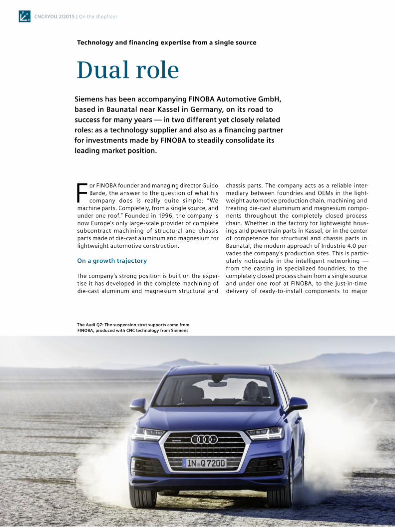
Dual role Siemens has been accompanying FINOBA Automotive GmbH, based in Baunatal near Kassel in Germany, on its road to success for many years — in two different yet closely related roles: as a technology supplier and also as a financing partner for investments made by FINOBA to steadily consolidate its leading market position.
Technology and financing expertise from a single source
The Audi Q7: The suspension strut supports come from FINOBA, produced with CNC technology from Siemens
CNC4YOU 2/2015 | On the shopfloor

21
automotive manufacturers. This complete process has many advantages and significantly reduces the number of interfaces in quality management and logistics management.
High pace of innovation
Those who wish to stay ahead of the competition in the components industry cannot afford to take their foot off the gas or slow down the pace of innovation. The drivers of growth at FINOBA are steering the company on a course that focuses on consistent modernization and optimization in the company’s traditional business segments. This is also opening the door for new lightweight construction applica-tions — for example, in interiors and powertrain. FINOBA is currently expanding its capacity for large-scale production and is further extending its center of competence for machining structural and chassis parts at the Baunatal site. The completely closed process chain implemented in connection with this development is unrivaled in Europe in terms of its size and degree of vertical integration.
The high-tech highlights of this chain are pro-vided by modern machinery, including automation robots, turning centers and linked CNC five-axis machining centers from Chiron, which are designed for complex machining programs, even on chal-lenging contour shapes. The controls required for high-performance machining and the precise work-manship demanded by the automotive industry are provided by Siemens in the form of industry-leading Sinumerik CNC tech nology.
Healthy balance sheets thanks to intelligent financing
Innovation not only requires technological excel-lence; it also needs to be appropriately financed. FINOBA therefore relies on a combination of tech-nology and financing from a single source. Every-thing the Siemens Digital Factory Division supplies is financed by Siemens Financial Services. A perfect example of this is a new production line for machining suspension strut supports for the Audi Q7 with state-of-the-art Chiron CNC technology and Siemens auto-mation and control technology. Siemens Financial Services financed the investment volume of around €4.4 million.
The decision to finance investments in equipment and machinery by leasing, therefore conserving both equity capital and liquidity, is contributing to healthy balance sheets at FINOBA. “The Siemens Financial Services staff who support us know our business and the market, respond very quickly to new challenges,
and show themselves to be highly qualified advisers when it comes to questions of residual value man-agement, value patterns or risk structure adjust-ment,” says Nicole Boguslawski, authorized repre-sentative and commercial director at FINOBA.
FIN
OB
A A
UTO
MO
TIV
E G
mb
H
INFO AND CONTACT
siemens.com/[email protected]
“ The Siemens Financial
Services staff who support us
know our business and the
market, respond very quickly
to new challenges, and show
themselves to be highly
qualified advisers when it
comes to questions of
residual value management,
value patterns or risk
structure adjustment.”Nicole Boguslawski, Authorized Representative and Commercial Director, FINOBA
On the shopfloor | CNC4YOU 2/2015

22
With the WRITE command, sets and data from the parts program can be written at the end of a speci-fied file (log file) or the parts program currently being executed. The data are inserted at the end of the file after M30. Alternatively, the data can be saved in a separate file directly onto a network com-puter or external data carrier.
Programs frequently measure values that need to be archived for further processing or even just for logging purposes. With the high-level com-
mand WRITE, this action can be done directly from the user program.
Structure of the WRITE instruction
The WRITE instruction contains the command invo-cation and, as parameters, the return variable, the filing location, the name of the file, and the text out-puts and instructions that are to be written to the file. The individual parameters are separated by commas.
Sinumerik high-level programming language: The WRITE command
Logging made easy
TIP
The meaning of the return values and further information on the WRITE command can be found in the work preparation programming manual.
WRITE(<ERROR>,“</_N_SPF_DIR/_N_
PROTOKOLLE_WPD/_N_PROT_MPF>“/“
<ExtG>“,“<BLOCK / DATA>“)
Invoking the WRITE command
Name of the variable for returning the error valueThis variable must be defined before the function call-up: DEF INT ERROR
Filing location and logging file path_N_SPF_DIR: Directory in the NC (SPF = subprogram file, MPF = main program file)
_N_PROTOKOLLE_WPD: Folder in the directory selected above
_N_PROT_MPF: Name of the log file with file extension MPF or SPFThe file name may contain only letters, numbers and underscores
Among the instructions, variables/parameters can also be called up in addition to text. These variables could contain the date, time, axis positions and measurement parameters, for example
Alternative ExtG:Specification of external data carrierMust be defined in advance with EXTOPEN. Example for the filing location: NC/SUBPROGRAMS/PROTOCOL/PROT.MPF
CNC4YOU 2/2015 | Tips & tricks

23
Logging measured values
With just a few NC sets, a log file can be created with set point and actual values using the WRITE com-mand. The approach can be briefly represented using Cycle977 as an example (measuring rectangular pockets).
In the first step, parameterize the Cycle977 mea-surement cycle and then define the return variable. For structuring purposes, the character string # START # is written in the log file using the WRITE command.
The date and time then need to be specified for documentation purposes. There are system variables for this, for example, $A_DAY for the day. Variables are bracketed with << and quotation marks in the WRITE command, for instance, “<<$A_YEAR<<”. Mea-surement cycles also save the measured values in variables. These are also written using the WRITE command. The measurement variables are firmly de-fined. In the sample program, the set point and ac-
INFO AND CONTACT
siemens.com/[email protected]
TIP
The variable names and their meanings can be found in the measuring cycles programming manual and in the system variables list manual.
tual values are written in the log file; for example, _OVR[0] is the set point value for the rectangle length in the first axis. Finally, the log is completed with the character string # END #.
Logging measured values using Cycle977 as an example: writing measured values in seven steps
(below); log file from the sample program (left)
Sie
men
s A
G
Siem
ens
AG
Tips & tricks | CNC4YOU 2/2015

24
A particular priority of the professors at Trier University of Applied Sciences is to teach techniques and processes that will be essential to the students later on in “real” life in industry. For this reason, they provide the future engineers with a machine park containing modern CNC machine tools equipped with Sinumerik 840D sl as well as a CAD/CAM room equipped with NX CAM.
Trier University of Applied Sciences teaches students using Sinumerik CNC and NX software
Future engineers should be taught as much practical knowledge as possible during their studies, since
the more practice-oriented the course is, the more quickly its learning can be integrated in operational processes. Dr. Peter Gutheil, dean of the faculty of environmental technology at the Birkenfeld Environmental Campus of Trier University of Applied Sciences, has devised a perfect solution. This year the machine park was expanded, with the addition of four modern machine tools. The most recent acquisition is the Spinner TC600 turning center with the Sinumerik 840D sl CNC. This was espe-cially important for the teachers be-cause, in addition to the Sinumerik CNC, the CAD/CAM software NX CAM, which is also from Siemens, is used for teach-ing purposes.
All programming methods are taught
Teaching industrial practice also means focusing the training on the different methods of CNC programming. The Sinumerik 840D sl, with the operating and programming software Sinumerik Operate, offers the right range of func-tions for this and is suitable for all ap-plications and industries.
The graphical programs ShopTurn for turning and ShopMill for milling are op-
tionally integrated for the program-ming of individual parts. ShopMill and ShopTurn programming is character-ized by its high ease of use. The pro-grams can be supplemented at any time with sequences from DIN/ISO pro-grams. This makes it possible to achieve maximum flexibility in workpiece pro-gramming. Sinumerik Operate offers the programGUIDE program editor as part of the standard version. If neces-sary, DIN/ISO codes can simply be writ-ten with programGUIDE and then sup-plemented with an extensive inventory of standard machining cycles.
“Having both methods in one control system increases flexibility tremen-dously,” emphasizes shopfloor foreman Christian Seibert. The process and envi-ronmental technology faculties contin-ually require various valves or other spare parts. But complex components are occasionally in demand for campus presentations, too. Seibert then pro-grams these directly on the machine: “With ShopMill, Sinumerik Operate pro-vides me with a very intuitive program-ming interface. It allows me to gener-ate every program in a targeted way, without errors, and much more quickly
Siem
ens
AG
Teaching and practice — hand in hand
The Siemens PLM Software educational support program supports more
than 12,000 academic institutions around the world. It provides a wide
variety of educational institutions — from secondary schools to
universities to special research programs — with software solutions such
as NX, Solid Edge, Tecnomatix, Teamcenter and Femap. With the PLM and
CAD/CAM/CAE software solutions, educational establishments have the
best conditions for teaching the students hands-on knowledge of digital
product design, simulation, analysis, production and product data
management.
If you would like to find out more about the Siemens PLM Software
training support program, please contact Karl Hermann Dietz
([email protected]) or take a look at the website siemens.com/plm.
SIEMENS PLM SOFTWARE EDUCATIONAL SUPPORT PROGRAM
CNC4YOU 2/2015 | Education

25
than using conventional G-code entry or CAD.”
Diverse design possibilities using CAD
The environmental campus has also been using the NX CAD/CAM program from Siemens PLM since 1996. Those in charge are very satisfied with the con-tinuing improvements and develop-ments. “This results in an enormous variety of design possibilities,” stresses Gutheil, adding, “Depending on the se-mester and the amount of interest, the students can learn everything from standard CAD to the finite element method to CAM and even postproces-sor programming.” Before the pro-grams are transferred to a machining center on the shopfloor, a simply struc-tured simulation can be accessed — a standard feature of NX. Stefan Hirsch, teacher of special tasks at the Birken-feld university site, also finds this fea-ture very helpful: “Especially during the first semesters, our students some-times design without consideration for what is feasible. But thanks to the sim-ulation, they can learn where they have made mistakes and how they can avoid them in the future.”
Learning how designs are imple-mented with CAD/CAM systems is one thing. But it is just as important to
know how the individual parts of the design are machined later in machin-ing centers. “Companies expect even young engineers to understand the entire production process and know what is technically feasible,” explains Hirsch. “That includes working with CAD/CAM systems as well as having knowledge of the performance of ma-chine tools.”
Continuous process chain
The consistency of both the Sinumerik CNC and the NX CAD/CAM software makes work easier for the lecturers as well as the shopfloor supervisors. The tools the TC600 machine is fitted with, as well as cycles such as Cycle800 (swiveling), Cycle832 (high-speed set-tings) and various drilling cycles, are integrated in NX and are transferred to-gether with the program to the control system via the postprocessor. Hirsch is extremely impressed: “I only have to enter the corresponding data once, and now they are available for every com-ponent to be produced.”
To ensure that his technology-oriented students also learn with a practical ori-entation during the theory semesters, he provides them with computers with modern NX9 CAD/CAM software from Siemens on which they can translate their ideas into designs. The campus re-
ceived around 100 licenses for this purpose through the Siemens PLM Software educational support program. The major advantage of this approach is that the engineers-to-be learn how to work with computer-based design software while still at the university. The professor identifies an additional benefit in that NX is a standard part of work preparation in many industries, such as automobile and aircraft manu-facturing, and medical technology: “We work with many well-known compa-nies that use NX and particularly appre-ciate the flexibility and openness of this software.” As the system has proven it-self so well, Gutheil can envisage add-ing to the existing 100 NX licenses in the future. This training philosophy at Trier University of Applied Sciences is an example of how it is possible to suc-cessfully collaborate with strong part-ners in industry to implement a perfect basis for practice-oriented teaching of engineers.
Siem
ens
AG
During the machining process, the students can see how their component ideas become reality in the Spinner TC600 turning center
University lecturer Stefan Hirsch transfers CAD/CAM data to the Sinumerik CNC
INFO AND CONTACT
siemens.com/[email protected]

CNC4YOU 2/2015 | News
26
eBooklet for EMO 2015
Reliable trade fair companion
Siem
ens
AG
Perhaps you have thought about viewing a machine for gear cutting or recommending a visit to a certain machine in the run-up to the trade fair. The EMO 2015 eBooklet from Siemens — an electronic reference guide
available via a standard browser — gives you access to more than 150 ma-chine tools with Sinumerik that will be showcased at this year’s EMO.
Are you thinking of planning your trade fair visit ahead of time? A simple machine search function allows you to filter the results by manufacturer and hall using a text search tool and quickly guides you to the right machine.
Perhaps you are already at the trade fair and would like to know which machines are located in the hall you are currently in — for instance, only ma-chines equipped with Sinumerik 828D. The results filter can help in this situ-ation, allowing you to select the relevant components, industries and ma-chine types in addition to the manufacturer and hall.
Or do you want to create a favorites list of machines for a colleague that is available offline for you at the fair? The offline favorites list enables you to save up to 10 selected machines with descriptions and images. You can also share and recommend individual entries from a favorites list by e-mail, Twitter, WhatsApp, and so on, directly from the trade fair.
siemens.com/emo-ebooklet
Visitors to EMO 2015 in Milan can download an eBooklet onto their smartphone, tablet or PC to serve as a useful companion before, during and after the trade fair.
EMO trade fair show — smart operation
Siemens is highlighting the motto “On the Way to Industrie 4.0 — Digitaliza-tion in Machine Tool Manufacturing” with an interesting and exciting show at the company’s EMO booth. The show reveals how digitalization can specifi-cally benefit shopfloor applications with smart operation. Two actors invite visitors to delve into the digital world of smart operation and represent the indi-vidual smartPrepare, smartOperate, smartMobile and smartIT solution packages. A large touchscreen acts as a membrane between the digital world and reality, which then merge to be-come a single entity.
Visit Siemens in Hall 3 and see for yourself the solutions available for dig-italization in the machine tool industry.
siemens.com/emo
Siem
ens
AG
Siem
ens
AG
First scan the QR code and then download the eBooklet

News | CNC4YOU 2/2015
27
Successful spindle workshop
Siemens subsidiary Weiss Spindeltech-nologie held its first spindle workshop at the company’s service center in Maroldsweisach, Germany, at the be-
Participants at the first Siemens-Weiss spindle workshop were given extensive information about spindles
Siem
ens
AG
Berlin Adlershof is one of the largest science parks in the world. Covering an area of 4.2 km², the park is home to re-search institutions, institutes and nu-merous companies — and now also to the learning factory Lernfabrik Neue Technologien Berlin. When the learning factory opened its modern technology and training center on May 27, 2015, a dream became reality for Michael Bose
Andre Zänker (right) from Siemens presents the CNC training partner certificate to Evelyn Schmidt and Michael Bose
Siem
ens
AG
ginning of this year. Production person-nel responsible for machining and ma-chine tools at a wide variety of Siemens sites were invited to attend the event, and participants were welcomed from almost every region of the German- speaking Siemens world. Oskar Neuner, head of customer care in repairs and service at Weiss, was delighted with the workshop’s success. “It was all about showing the participants the wide range of services for motor spindle units that we are able to offer within the Siemens family, as well as the kinds of strategies that can be employed to minimize machine downtimes,” says Neuner. “The members of our product management team also brought their Siemens colleagues up to date with the latest developments in motor spindle technology.”
In addition to a tour of the company’s premises and a presentation on the lat-est product and service portfolio from Weiss, the agenda for the first work-shop included an overview of the repair
INFO AND CONTACT
siemens.com/[email protected]
INFO AND CONTACT
siemens.com/[email protected]
and Evelyn Schmidt. The project is fi-nanced by a privately funded nonprofit limited company, with the support of industrial companies. Siemens is part of the network as one of the project part-ners. “We are an approved Siemens training partner,” says Schmidt. Siemens representatives Andre Zänker and Enrico Ehrhardt from Chemnitz took the opening ceremony as an opportu-
process on-site. Attendees also com-pared notes on maintenance and many other spindle-related topics. The spindle specialists at Weiss will be incorporating these expert responses into the services they offer in the future, thus enabling them to provide even more focused support for their end customers.
Based on the positive feedback for the first Siemens-Weiss spindle work-shop, the organizers have decided to hold more events of this kind at regu-lar intervals. The next event will focus on harnessing existing potential for condition monitoring for motor spin-dle units. Those interested in partici-pating are invited to sign up now at [email protected].
New learning factory with Sinumerik
nity to present Bose and Schmidt with the recognized CNC training partner certificate.
Since April the learning factory has been training young metalworkers as CNC specialists using brand-new CNC equipment from DMG Mori. The learning factory has no intention of being just another educational provider. “We want to work with and for industry in order to train our participants as they work on real orders,” says project manager Schmidt.

Increased efficiency, enhanced flexibility and shorter time to market – all this is promised by digitalization. Whether inte-grated engineering in machine develop-ment or networking machine tools in a production landscape:
We support machine builders as well as machine tool users with our solutions! The basis is always our SINUMERIK® CNC with its openness and technological bandwidth.
siemens.com / emo
Digitalization inMachine Tool Manufacturing
Show and presentations at the Siemens booth
EMO MilanOctober 5-10, 2015Hall 3, E06 / F03
E20001-F730-P610-X-7600_Digitalization_in Machine_Tool_Manufacturing_210x280_emo-EN.indd 1 09.09.15 13:15