compensation of reactive power in grid-connected solar pv
TRANSCRIPT
International Journal of Engineering Trends and Technology Volume 69 Issue 10, 128-136, October, 2021 ISSN: 2231 – 5381 /doi:10.14445/22315381/IJETT-V69I10P216 ©2021 Seventh Sense Research Group®
This is an open access article under the CC BY-NC-ND license (http://creativecommons.org/licenses/by-nc-nd/4.0/)
Compensation of Reactive Power in Grid-
Connected Solar PV Array System Using
STATCOM and Fixed Capacitor Bank
CH Venkata Ramesh1, A Manjunatha2
1 Assistant Professor, Department of E&EE, NMIT, Bangalore. 2Professor, Department of E&EE, SKIT, Bangalore and affiliated to Visvesvaraya Technological University, Belagavi,
Karnataka, India [email protected], 2 [email protected]
Abstract - In this article, we propose reactive
compensation for the PV integrated grid system using a STATCOM and a fixed capacitor bank. This paper
presents a design calculation for a PV integrated grid
system with a fixed capacitor and STATCOM. The
proposed system is simulated and tested using the
MATLAB Simulink software package. The suggested
system has been evaluated under a variety of operating
circumstances, including changing solar PV array
irradiance and changing reactive load power. Detailed
simulation and comparisons between the fixed capacitor
and STATCOM represented.
Keywords — Solar PV system, Grid integration, Fixed capacitor, STATCOM, Reactive power compensation.
I. INTRODUCTION
Because of the world's growing infrastructure and
population, electric power and energy consumption is
increasing every day. These energy demands and power demands can be met by constructing new conventional
power plants such as thermal and hydropower stations.
There is a problem in the conventional power plant, such
as it produces greenhouse gas, occupies a large area for
construction, and needs a continuous supply of raw
materials to produce electrical energy. A non-conventional
power plant or renewable power plant is developed to
overcome the above-stated problems [1-2]. The solar PV
system is attracting the current electrical energy generation
sector due to ease of installation, ease in controlling of the
plant; the Manufacturing price of the PV panel is very low
when compared to another renewable energy plant [3-4]. A combination of serial and parallel is commonly used
in PV arrays to create photovoltaic PV array plants. By
connecting the PV panels in series, the PV plant voltage
will be raised, and the current rating of the solar PV power
plant may be enhanced by connecting the PV panels in
parallel. After making series and parallel connections, it
needs to be connected to the load or connected to the grid.
Generally, grid integration of the solar PV array can be
done in two ways one is single stage connection, and
another one is double stage connection. In a single-stage
connection, the grid is directly integrated into the PV array via a grid-tied inverter with some grid control logic, and
this method of connection is only useful when the terminal
voltage of the PV array is within the specified level. If the
PV array's terminal voltage is low, a double-stage
connection is recommended. In double stage connection, PV array voltage is step up to required standard level using
direct current setup converter, and then direct current step-
up converter output is integrated to the grid via a grid-tied
inverter to share the power. When solar PV array voltage is
very high (high than standard value), double stage
connection system should use step down direct current
converter between grid-tied inverter and solar PV array [5-
7].
The most important thing in the solar PV integrated grid
system is reactive power compensation. The real power
only is supplied to the load by using a PV array system,
and also excess real power is shared to the grid, and reactive power is not shared by the PV array system [8-12].
If the load requires any reactive power, then the grid has to
provide reactive load power. The reactive power
compensation in the load side can be done by using a
capacitor bank [13-17]. But reactive power compensation
by fixed capacitor bank has some demerits such as reactive
power supplied by the fixed capacitor is always constant
based on installed capacitor bank in the load side, i.e., the
requirement of the reactive power in the load side is less
than the installed capacity of the capacitor bank then
power factor in the load side goes to leading, and if reactive power requirement by the load is high than the
installed capacity of the capacitor bank, then power factor
in the load side is lagging. Due to this, the penalty will
give to the consumer by the energy supplying company
[17-22]. In this paper, STATCOM is presented for solar
PV array integrated grid system to compensate the reactive
power dynamically to overcome the problem in the fixed
capacitor bank.
The paper is vv organized in the following way: Design
of solar PV panel array, harmonic filter in the grid-tied
inverter, DC-DC converter, the harmonic filter of the
STATCOM side, and fixed capacitor bank is presented in section II. The simulation of solar PV array integrated grid
system with different operating are explained in section III.
In section IV provides the closing remarks of the proposed
work.

CH Venkata Ramesh & A Manjunatha. / IJETT, 69(10), 128-136, 2021
129
Fig. 1Grid connected system with STATCOM and fixed capacitor.
II. DESIGN OF SOLAR PHOTOVOLTAIC GRID
SYSTEM WITH STATCOM AND FIXED
CAPACITOR In this section, the design of the Photovoltaic grid-
connected system, the design of STATCOM, and the fixed
capacitor are explained. Fig.1 shown the functional
diagram of the solar Photovoltaic grid system with
STATCOM and fixed capacitor.
The system consists of a solar Photovoltaic array, grid-
tied inverter for integration of solar Photovoltaic, DC-DC
boost converter, LCL filter in the inverter of the solar PV
side, STATCOM dc-link capacitor, voltage source inverter,
LCL filter in the statcom side, and fixed capacitor. DC-DC
converter used for integrating Solar PV array with the grid-
tied inverter. A three-phase grid is integrated into a grid-tied inverter via LCL (Inductor – Capacitor - Inductor)
filter. STATCOM, a three-phase Voltage source inverter,
is integrated into the three-phase grid is connected via an
LCL filter. The fixed capacitor is integrated directly into
the three-phase grid via three circuit breakers.
Fig. 1 For varying irradiances, the P-V and I-V
characteristics of the considered Solar PV array.
A. Design of Solar PV array system
The solar PV panel system can be formed through
parallel and series integration of the different solar PV panels. The series connection of the solar PV panel will
increase the solar PV panel array terminal voltage, and the
parallel connection of the solar PV panel array will
increase the solar PV panel array current rating. The rating
of the single panel is 213.15 W, maximum power point PV
panel voltage is 29 V, PV panel voltage at the open circuit
is 36.3 V, PV current at the short circuit is 7.84 A, and
maximum power point cutter is 7.35 A. series-connected
PV panel is 10, and parallel-connected PV panel is 47. The
overall rating of the solar PV array is 100.345 kW, PV
panel voltage at the open circuit is 363 V, PV current at the
short circuit is 368.48 A, maximum power point current is 345.45 A, and maximum power point voltage is 290 v.
Fig.2 shows the power-voltage and current-voltage
characteristics of the consider solar PV array for different
irradiance conditions. The solar PV array has maximum
power is 9.72 kW at 100 W/m2 and 25C, maximum power
is 50.75 kW at 500 W/m2 and 25C and maximum power
is 100.345 kW at 1000 W/m2 and 25C.
Fig. 2 For varying temperatures, the P-V and I-V
characteristics of the considered Solar PV array.

CH Venkata Ramesh & A Manjunatha. / IJETT, 69(10), 128-136, 2021
130
Figure 3 Depicts the P-V and I-V characteristics of the considered Solar PV under consideration for various
temperatures. The solar PV has maximum power is 104.1
kW at 15C and 1000 W/m2, maximum power is 100.345
kW at 25C and 1000 W/m2, maximum power is 98.78 kW
at 35C and 1000 W/m2, and maximum power is 95.03 kW
at 45C and 1000 W/m2.
B. Design of DC-DC Boost Converter
The direct current – direct current step-up converter is
designed based on voltage and power ratings of the solar
PV array and output voltage requirement of the grid-tied
inverter. The standard testing condition ratings of the solar
PV are 290 V and 100.345 kW, respectively. The output
voltage requirement or DC link requirement for the grid-
tied inverter is 700 V. the following equation used to
design the inductor and capacitor of the direct current – direct current step-up converter in the solar PV system for
grid integration [23],
𝐼𝑜𝑢𝑡𝑚𝑎𝑥 =𝑃
𝑉𝑜𝑢𝑡 (1)
∆𝐼𝐿 = 0.07 × 𝐼𝑜𝑢𝑡𝑚𝑎𝑥 ×𝑉𝑜𝑢𝑡
𝑉𝑖𝑛 (2)
∆𝑉𝑜𝑢𝑡 = 0.007 × 𝑉𝑜𝑢𝑡 (3)
𝐿 =𝑉𝑖𝑛×(𝑉𝑜𝑢𝑡−𝑉𝑖𝑛)
∆𝐼𝐿×𝐹𝑠×𝑉𝑜𝑢𝑡 (4)
𝐶 =𝐼𝑜𝑢𝑡𝑚𝑎𝑥×(1−
𝑉𝑖𝑛𝑉𝑜𝑢𝑡
)
∆𝑉𝑜𝑢𝑡×𝐹𝑠 (5)
Where L in the filter inductor of the direct current –
direct current step-up converter, C is the filter capacitor of
the direct current – direct current step-up converter,
standard test condition power rating of solar PV is denoted
as P and 𝑉𝑖𝑛 is PV voltage at standard test conditions,
𝐼𝑜𝑢𝑡𝑚𝑎𝑥 is the maximum current of the converter at the
terminal of the direct current – direct current step-up
converter,𝑉𝑜𝑢𝑡is the output voltage of the direct current –
direct current step-up converter, ∆𝐼𝐿 is the ripple inductor
current of the direct current – direct current step-up
converter, ∆𝑉𝑜𝑢𝑡 is the ripple output voltage of the direct
current – direct current step-up converter and 𝐹𝑠 is the
switching frequency of the direct current – direct current
step-up converter.
The maximum current of the direct current – direct
current step-up converter at the output terminal is,
𝐼𝑜𝑢𝑡𝑚𝑎𝑥 =100.345 × 1000
700= 143.35 𝐴
The ripple inductor current of the direct current – direct
current step-up converter is,
∆𝐼𝐿 = 0.07 × 143.34 ×700
290= 24.21 𝐴
The ripple inductor voltage of the direct current – direct
current step-up converter is,
∆𝑉𝑜𝑢𝑡 = 0.007 × 700 = 4.9 𝑉
The designed value of the inductor of the direct current
– direct current step-up converter is,
𝐿 =290 × (700 − 290)
24.21 × 5000 × 700= 1.4 𝑚𝐻
The designed value of the capacitor of the direct current
– direct current step-up converter is,
𝐶 =143.35 × (1 −
290
700)
4.9 × 5000= 3400 𝜇𝐹
C. Grid-tied inverter harmonic Filter design
The harmonic filter for the grid-tied inverter is designed
based on solar power ratings, switching frequency of the
inverter, dc-link voltage, grid voltage, and grid frequency.
The following equation used for the design of harmonic
LCL filter for grid-tied inverter [24-25],
𝜔𝑔 = 2 × 𝜋 × 𝑓𝑔 (6)
Fig. 3 Simulink model of photovoltaic solar array integrated grid system with fixed capacitor bank
and STATCOM.
CH Venkata Ramesh & A Manjunatha. / IJETT, 69(10), 128-136, 2021
131
𝑍𝑏 =𝑉𝑔
2
(𝑃
3) (7)
𝐶𝑏 =1
𝜔𝑔×𝑍𝑏 (8)
𝐼𝑚𝑎𝑥 =𝑃×√2
3×𝑉𝑔×0.9 (9)
∆𝐼𝑚𝑎𝑥 =10
100× 𝐼𝑚𝑎𝑥 (10)
𝐿1 =𝑉𝑜𝑢𝑡
6×𝐹𝑠𝑤×∆𝐼𝑚𝑎𝑥 (11)
𝐶𝑔 = 0.05 × 𝐶𝑏 (12)
𝐿2 =√
1
0.22+1
𝐶𝑔×(2×𝜋×𝐹𝑠𝑤)2 (13)
𝜔𝑟𝑒𝑠 = √𝐿1+𝐿2
𝐿1×𝐿2×𝐶𝑔 (14)
𝜔𝑚𝑖𝑛 = 10 × 𝑓𝑔 (15)
𝜔𝑚𝑎𝑥 = 0.5 × 𝐹𝑠𝑤 (16)
Where, 𝑓𝑔 is the grid frequency, 𝑉𝑔 is the grid voltage
per phase,𝜔𝑔 angular frequency in radians of the grid, 𝑍𝑏 is
per phase impedance of the harmonic filter, 𝐶𝑏 is the
harmonic filter base capacitance, 𝐼𝑚𝑎𝑥 is the harmonic
filter maximum current rating, ∆𝐼𝑚𝑎𝑥 is the harmonic filter
maximum current ripple of the filter inductor, 𝐿1 is the
input side filter inductor of the harmonic filter, 𝐿2 is
harmonic filter output side filter inductor, 𝐶𝑔 is harmonic
filter capacitor of the, 𝜔𝑟𝑒𝑠 is the resonance frequency of
harmonic filter in radians, 𝜔𝑚𝑖𝑛 is the minimum frequency
limit of the harmonic filter and 𝜔𝑚𝑎𝑥 is the maximum
frequency limit of the harmonic filter.
The angular frequency of the grid system is given by,
𝜔𝑔 = 2 × 𝜋 × 50 = 314.1593 𝑟𝑎𝑑/𝑠
The per impedance of the harmonic filter is given by,
𝑍𝑏 =2302
(100.345 ×1000
3)
= 1.5870
The base capacitance of the harmonic filter is given by,
𝐶𝑏 =1
314.1593 × 1.5870= 0.002
The maximum current rating of the harmonic filter is
given by,
𝐼𝑚𝑎𝑥 =100.345 × 1000 × √2
3 × 230 × 0.9 = 227.7317 𝐴
The maximum ripple inductor of the harmonic filter is
given by,
∆𝐼𝑚𝑎𝑥 =10
100× 227.7317 = 22.7732 𝐴
The input side filter inductor of the harmonic filter is
given by,
𝐿1 =700
6 × 10000 × 22.7732= 0.6 𝑚𝐻
The filter capacitor of the harmonic filter is given by,
𝐶𝑔 = 0.05 × 0.002 = 100.29 𝜇𝐹
The outside filter inductor of the harmonic filter is given
by,
𝐿2 =
√1
0.22 + 1
100.29 × 10−6 × (2 × 𝜋 × 10000)2= 15 𝜇𝐻
D. Design of harmonic Filter for STATCOM
The harmonic filter for STATCOM is designed based
on the reactive power requirement, dc-link voltage, grid voltage, the switching frequency of the inverter, and grid
frequency. A similar equation from (6) to (16) is followed
for the design of the harmonic filter of the STATCOM.
The designed value of the input side inductor of the
harmonic filter in the STATCOM is 0.6 mH, the designed
value of the output side inductor of the harmonic filter in
the STATCOM is 15.15 µH, and the designed value of the
capacitor of the harmonic filter in the STATCOM is
100.29 µF.
E. Design of Fixed capacitor bank ratings
The reactive power rating of the fixed capacitor bank is
determined by the load side's reactive power requirement.
A 100 kVAr reactive power capacitor bank is used in this
work for reactive power compensation.
III. SIMULATION RESULTS AND DISCUSSION
In this section, investigation of reactive power
compensation for a PV grid system with STATCOM and a
fixed capacitor bank under various operating conditions.
Figure 4 depicts the overall Simulink model of the
proposed PV grid system.
The system suggested was tested under the following
operating conditions, grid-connected solar PV array system
supplying power to the load locally, irradiance variation,
and reactive power compensation in a PV grid system
along with a fixed capacitor bank, and reactive power
compensation in a PV array integrated grid system with a STATCOM.
A. Simulation results of the PV integrated grid system
with supplying only real power into the grid and
supplying local load(Case 1)
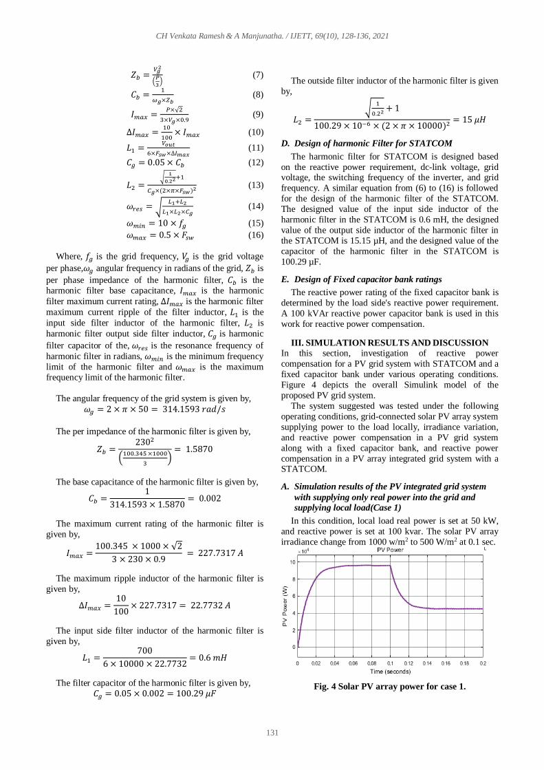
In this condition, local load real power is set at 50 kW,
and reactive power is set at 100 kvar. The solar PV array
irradiance change from 1000 w/m2 to 500 W/m2 at 0.1 sec.
Fig. 4 Solar PV array power for case 1.

CH Venkata Ramesh & A Manjunatha. / IJETT, 69(10), 128-136, 2021
132
Fig.5 shows the solar PV array power variation of a
solar PV array as the irradiance changes from 1000 W/m2
to 500 W/m2 over 0.1 seconds. The maximum power of
solar PV panels at 1000 W/m2 is 95.61 kW and at 500
W/m2 is 44.86 kW. The solar PV inverter's reactive and real power is depicted in Fig.6. The PV inverter voltage,
inverter current, and DC link voltage are shown in Fig.7.
Fig. 5 Solar PV inverter real reactive power for
case 1.
Fig. 6 PV inverter dc-link voltage, voltage, and current
for case 1.
Fig. 7 Grid reactive and real power for case 1.
The grid's reactive and real power is depicted in Fig.8. the
grid's real power is -44.8 kW during 1000 W/m2 irradiance
i.e., the grid receiving real power from the solar PV
inverter and 892 W during 500 W/m2 irradiances i.e., grid
supplying real power to load. The reactive power of the grid is 100.1 kvar. The grid voltage and grid current is
depicted in Fig.9.
Fig. 8 Grid current and grid voltage for case 1.
Fig. 9 Load reactive and real power for case 1.
Fig. 10 Load voltage and current for case 1.
The load reactive power and real power are depicted in Fig.10. the load real power is 50 kW during 1000 W/m2
irradiance and 50 kW during 500 W/m2 irradiances. The
load reactive power is around 100 kVAr. The load current
and load voltage is depicted in Fig.11.
B. Simulation results of the solar PV array integrated
grid system with Fixed capacitor bank (Case 2)
In this condition, local load real power is set at 100 kW,
and reactive power is set at 150 kVAr. The PV array
CH Venkata Ramesh & A Manjunatha. / IJETT, 69(10), 128-136, 2021
133
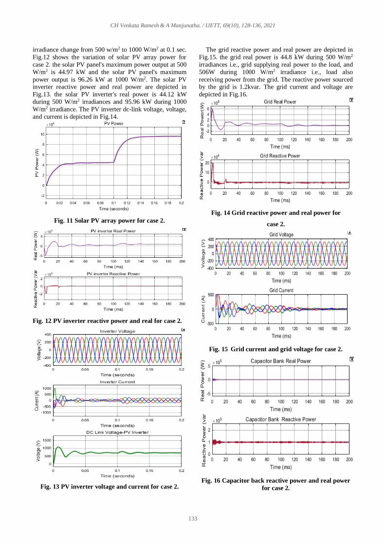
irradiance change from 500 w/m2 to 1000 W/m2 at 0.1 sec.
Fig.12 shows the variation of solar PV array power for
case 2. the solar PV panel's maximum power output at 500
W/m2 is 44.97 kW and the solar PV panel's maximum
power output is 96.26 kW at 1000 W/m2. The solar PV inverter reactive power and real power are depicted in
Fig.13. the solar PV inverter's real power is 44.12 kW
during 500 W/m2 irradiances and 95.96 kW during 1000
W/m2 irradiance. The PV inverter dc-link voltage, voltage,
and current is depicted in Fig.14.
Fig. 11 Solar PV array power for case 2.
Fig. 12 PV inverter reactive power and real for case 2.
Fig. 13 PV inverter voltage and current for case 2.
The grid reactive power and real power are depicted in
Fig.15. the grid real power is 44.8 kW during 500 W/m2
irradiances i.e., grid supplying real power to the load, and
506W during 1000 W/m2 irradiance i.e., load also
receiving power from the grid. The reactive power sourced by the grid is 1.2kvar. The grid current and voltage are
depicted in Fig.16.
Fig. 14 Grid reactive power and real power for
case 2.
Fig. 15 Grid current and grid voltage for case 2.
Fig. 16 Capacitor back reactive power and real power
for case 2.

CH Venkata Ramesh & A Manjunatha. / IJETT, 69(10), 128-136, 2021
134
Fig. 17 Capacitor bank voltage and current for case 2.
The capacitor bank reactive power and real power and is
depicted in Fig.17. the capacitor bank real power is 1.3 kW.
The capacitor bank supplying reactive power to load is
around 100kVAr. The capacitor bank voltage, the current
is shown in Fig.18.
Fig. 18 Load reactive power and real power for
case 2.
Fig. 19 Load current and voltage for case 2.
The load real power and reactive power are shown in
Fig.19. the load real power is 100 kW during 1000 W/m2 irradiance and 100 kW during 500 W/m2 irradiances. The
reactive power of the load is 100 kVAr. The load voltage,
the current are displayed in Fig.20.
C. Simulation results of the PV integrated grid system
with STATCOM (Case 3)
In this condition, local load real power is set at 10 kW,
and reactive power is set at 150 kVAr. The solar PV array
irradiance change from 500 w/m2 to 1000 W/m2 at 0.1 sec.
Fig. 20 Solar PV array power for case 3.
Fig.21 shows the solar PV array power variation for
irradiance change from 500 W/m2 to 1000 W/m2at 0.1 sec.
the solar PV array maximum power at 500 W/m2 is 44.99
kW and the solar PV array maximum power is 96.3 kW at
1000 W/m2. The solar PV inverter reactive power and real power are depicted in Fig.22. the solar PV inverter's real
power is 44.15 kW during 500 W/m2 irradiances and 95.99
kW during 1000 W/m2 irradiance. The PV inverter dc-link
voltage, voltage, and current are seen in Fig.23.
Fig. 21 PV inverter reactive power and real power for
case 3.
Fig. 22 PV inverter voltage and current for case 3.

CH Venkata Ramesh & A Manjunatha. / IJETT, 69(10), 128-136, 2021
135
Fig. 23 Grid reactive power and real power for case 3.
The grid reactive power and real power are seen in
Fig.24. The grid real power is 1.3 kW during 500 W/m2
irradiances i.e., grid supplying real power to the load. The
grid's reactive power is 1.2 kVAr. The grid current and
voltage are depicted in Fig.25.
Fig. 24 Grid current and voltage for case 3.
Fig. 25 STATCOM reactive power and real power for
case 3.
Fig. 26 STATCOM dc-link voltage, voltage, and
current for case 3.
The STATCOM reactive power and real power are
depicted in Fig.26. The STATCOM real power is 800 w.
The reactive power of the STATCOM is 150.2kvar. The
STATCOM voltage, current, and dc-link voltage are
shown in Fig.27.
Fig. 27 Load reactive power and real for case 3.
Fig. 28 Load current and voltage for case 3.

CH Venkata Ramesh & A Manjunatha. / IJETT, 69(10), 128-136, 2021
136
The load reactive power and real power are depicted in
Fig.28. the load real power is 100 kW during 1000 W/m2
irradiance and 100 kW during 500 W/m2 irradiances. The
load reactive power is around 150 kVAr. The load current
and voltage are depicted in Fig.29.
IV. CONCLUSIONS
This study shows how to use STATCOM and a fixed
capacitor bank to compensate for reactive power in a grid-
connected solar PV array. This article explains how to
design a solar PV system, a DC-DC boost converter, a
grid-tied inverter, and a STATCOM voltage source inverter. The suggested system's whole model is simulated
using the MATLAB Simulink software suite. The grid-
connected photovoltaic solar array system has been tested
under different operating conditions, without fixed
capacitor and STATCOM and fixed capacitor and
STATCOM for reactive power compensation. From the
simulation results, reactive power of the grid-connected
solar PV array system is compensated effectively and
dynamically by STATCOM based on reactive power
requirement in the load side. In the grid-connected solar
PV array system, STATCOM's performance in reactive power compensation is better than that of fixed capacitor
banks.
REFERENCES [1] Aleem, S.A.; Hussain, S.M.S.; Ustun, T.S. A Review of Strategies
to Increase PV Penetration Level in Smart Grids. Energies (2020),
13, 636.
[2] Vavilapalli, S.; Padmanaban, S.; Subramaniam, U.; Mihet-Popa, L.
Power Balancing Control for Grid Energy Storage System in
Photovoltaic Applications—Real-Time Digital Simulation
Implementation. Energies (2017), 10, 928.
[3] Karimi, M.; Mokhlis, H.; Naidu, K.; Uddin, S.; Bakar, A.H.A.
Photovoltaic penetration issues and impacts in distribution
network—A review. Renew. Sustain. Energy Rev., 53 (2016) 594–
605.
[4] Kow, K.W.; Wong, Y.W.; Rajkumar, R.K.; Rajkumar, R.K. A
review on the performance of artificial intelligence and
conventional method in mitigating PV grid-tied related power
quality events. Renew. Sustain. Energy Rev, 56 (2016) 334–346.
[5] Beres, R.N.; Wang, X.; Liserre, M.; Blaabjerg, F.; Bak, C.L. A
review of passive power filters for three-phase grid-connected
voltage-source converters. IEEE J. Emerg. Sel. Top. Power
Electron., 4 (2016) 54–69.
[6] Barrios-Martínez, E.; Ángeles-Camacho, C. Technical comparison
of FACTS controllers in parallel connection. J. Appl. Res. Technol.
15 (2017) 36–44.
[7] Xu, C.; Chen, J.; Dai, K. Carrier-Phase-Shifted Rotation Pulse-
Width-Modulation Scheme for Dynamic Active Power Balance of
Modules in Cascaded H-Bridge STATCOMs. Energies 13 (2020)
1052.
[8] Najjar, M.; Moeini, A.; Bakhshizadeh, M.K.; Blaabjerg, F.;
Farhangi, S. Optimal Selective Harmonic Mitigation Technique on
Variable DC Link Cascaded H-Bridge Converter to Meet Power
Quality Standards. IEEE J. Emerg. Sel. Top. Power Electron.,
4(2016) 1107–1116.
[9] Soodi, H.A.; Vural, A.M. Design, Optimization and Experimental
Verification of a Low-Cost Two-Microcontroller Based
SinglePhase STATCOM. IETE J. Res. (2021).
[10] Tareen, W.U.K.; Aamir, M.; Mekhilef, S.; Nakaoka, M.;
Seyedmahmoudian, M.; Horan, B.; Memon, M.A.; Baig, N.A.
Mitigation of Power Quality Issues Due to High Penetration of
Renewable Energy Sources in Electric Grid Systems Using Three-
Phase APF/STATCOM Technologies: A Review. Energies,
11(2018) 1491.
[11] Sirjani, R.; RezaeeJordehi, A. Optimal placement and sizing of
distribution static compensator (D-STATCOM) in electric
distribution networks: A review. Renew. Sustain. Energy Rev., 77
(2017) 688–694.
[12] Sajadi, R.; Iman-Eini, H.; Bakhshizadeh, M.K.; Neyshabouri, Y.;
Farhangi, S. Selective harmonic elimination technique with control
of capacitive DC-link voltages in an asymmetric cascaded H-
Bridge Inverter for STATCOM Application. IEEE Trans. Ind.
Electron., 65 (2018) 8788–8796.
[13] Diab, A.; Ebraheem, T.; Aljendy, R.; Sultan, H.; Ali, Z. Optimal
Design and Control of MMC STATCOM for Improving Power
Quality Indicators. Appl. Sci., 10 (2020) 2490.
[14] Ayala-Chauvin, M.; Kavrakov, B.S.; Buele, J.; Varela-Aldás, J.
Static Reactive Power Compensator Design, Based on Three-Phase
Voltage Converter. Energies, 14 (2021) 2198.
[15] Mehrasa, M.; Pouresmaeil, E.; Zabihi, S.; Rodrigues, E.M.G.;
Catalão, J.P.S. A control strategy for the stable operation of shunt
active power filters in power grids. Energy, 96 (2016) 325–334.
[16] Sridhar, V.; Umashankar, S. A comprehensive review on CHB
MLI based PV inverter and feasibility study of CHB MLI based
PV-STATCOM. Renew. Sustain. Energy Rev. 2017, 78, 138–156.
[17] Liu, X.; Lv, J.; Gao, C.; Chen, Z.; Chen, S. A Novel STATCOM
Based on Diode-Clamped Modular Multilevel Converters. IEEE
Trans. Power Electron., 32 (2017) 5964–5977.
[18] Luo, L.; Gu, W.; Zhang, X.-P.; Cao, G.; Wang, W.; Zhu, G.; You,
D.; Wu, Z. Optimal siting and sizing of distributed generation in
distribution systems with PV solar farm utilized as STATCOM
(PV-STATCOM). Appl. Energy, 210 (2018) 1092–1100.
[19] Sreedharan, S.; Joseph, T.; Joseph, S.; Chandran, C.V.; Vishnu, J.;
Das, V. Power system loading margin enhancement by optimal
STATCOM integration—A case study. Comput. Electr. Eng., 81
(2020) 106521.
[20] Gandhar, A.; Gupta, S.; Gandhar, S. Improvement of transient
stability margin in RES Based Power Systems Using STATCOM.
Asian J. Water Environ. Pollut., 15 (2018) 1–4.
[21] Tareen, W.U.K.; Aamir, M.; Mekhilef, S.; Nakaoka, M.;
Seyedmahmoudian, M.; Horan, B.; Memon, M.A.; Baig, N.A.
Mitigation of power quality issues due to high penetration of
renewable energy sources in electric grid systems using three-
phase APF/STATCOM technologies: A review. Energies, 11(2018)
1491.
[22] Popavath, L.; Kaliannan, P. Photovoltaic-STATCOM with Low
Voltage Ride through Strategy and Power Quality Enhancement in
a Grid Integrated Wind-PV System. Electronics, 7 (2018) 51.
[23] Ertao, L.; Yin, X.; Zhang, Z.; Chen, Y. An Improved Transformer
Winding Tap Injection DSTATCOM Topology for Medium-
Voltage Reactive Power Compensation. IEEE Trans. Power
Electron., 33(2018) 2113–2126.
[24] Afzal, M.M.; Khan, M.A.; Hassan, M.A.S.; Wadood, A.; Uddin,
W.; Hussain, S.; Rhee, S.B. A Comparative Study of
SupercapacitorBased STATCOM in a Grid-Connected
Photovoltaic System for Regulating Power Quality Issues.
Sustainability, 12 (2020) 6781.
[25] Espi, J.; Garcia-Gil, R.; Castello, J. Capacitive Emulation for LCL-
Filtered Grid-Connected Converters. Energies, 10 (2017) 930.