compatibility issues in design and implementation of
TRANSCRIPT

Report No. MERL-2014-87
Compatibility Issues in Design and Implementation of Concrete Repairs and Overlays Project ID: 0385
1. 2. U.S. Department of the Interior Bureau of Reclamation Technical Service Center Materials Engineering and Research Laboratory Denver, Colorado December 2014

Mission Statements The U.S. Department of the Interior protects America’s natural resources and heritage, honors our cultures and tribal communities, and supplies the energy to power our future. The mission of the Bureau of Reclamation is to manage, develop, and protect water and related resources in an environmentally and economically sound manner in the interest of the American public.

BUREAU OF RECLAMATION Technical Service Center, Denver, Colorado Materials Engineering and Research Laboratory, 86-68180 Report No. MERL-2014-87
Compatibility Issues in Design and Implementation of Concrete Repairs and Overlays
Project ID 0385 by Alexander M. Vaysburd Benoît Bissonnette Kurt F. von Fay
3.
U.S. Department of the Interior Bureau of Reclamation Technical Service Center Materials Engineering and Research Laboratory Denver, Colorado December 2014

Report No. MERL-2014-87 Compatibility Issues in Design and Implementation of
Concrete Repairs and Overlays – Project ID 0385
Executive Summary Many concrete repair materials can crack and/or debond after only a short period of time (a few months to a few years), setting the stage for premature repair failure by allowing ingress of water, air, chlorides, and other contaminants into the concrete. These contaminants can lead to further deterioration of the concrete and corrosion of steel reinforcement. Industry-wide, a majority of concrete repairs are estimated to last only about 5 to 7 years. The Bureau of Reclamation’s Science and Technology program provided funding for a scoping study on material compatibility issues of concrete repair materials with existing concrete. This paper builds on work funded by Douglas Burke through the Office of the Secretary of Defense, Corrosion Prevention and Control Program, Naval Facilities Engineering Command, Port Hueneme, California and draws from the years of experience of the authors. The goal of this paper is to present the basis for developing relevant design rules and technical guidelines for achieving durable concrete repairs and overlays, as well as to identify areas where additional studies on material compatibility issues are warranted. A great deal of work has been done establishing requirements for surface conditioning for successful repairs. Unfortunately, there is still no reliably accepted approach or methodology for selecting a repair material based on compatibility needs that can ensure a successful outcome for a repair or overlay project. The available information essentially consists of general, often misleading statements and recommendations that rely on overly simplified design considerations. This report will discuss topics such as the following:
• The composite structure of a repair and various repair functions;
• Different compatibility factors and negative effects of incompatibility;
• Guidance on the process of specification and selection of repair materials;
• Bond in composite repair/overlay systems.
Finally, recommendations for further studies to address the incomplete knowledge in the field of repair compatibility will be presented.
v
Report No. MERL-2014-87 Compatibility Issues in Design and Implementation of
Concrete Repairs and Overlays – Project ID 0385
Table of Contents Page
I. Background .................................................................................. 15
II. Concrete Repair: A Composite System Approach to Improve Results .......................................................................................... 17
A. General ..................................................................................... 18 B. System Concept ....................................................................... 19 C. Repair – A Composite System ................................................. 21 D. Concrete Repair Process ......................................................... 23 E. Systematic Design of a Repair Project ..................................... 24 F. Repair Versus New Construction as an Engineering Task ....... 28 G. Classification of Repair Functions ............................................ 29
III. Compatibility Factors and Properties ........................................ 35
A. Definition of Compatibility in Concrete Repair .......................... 36 B. Dimensional Compatibility ........................................................ 39
1. Components of Dimensional Compatibility .......................... 39 2. Tensile Strength .................................................................. 42 3. Shrinkage ............................................................................ 45 4. Modulus of Elasticity ........................................................... 51 5. Creep .................................................................................. 56 6. Thermal Extension .............................................................. 60
C. Permeability Compatibility ........................................................ 63 1. Permeability in Repair ......................................................... 63 2. Stress Effect on Permeability .............................................. 66 3. Permeability and Cracking .................................................. 67 4. Micropermeability and Macropermeability ........................... 69 5. Testing the Micropermeability ............................................. 72
D. Electrochemical Compatibility ................................................... 73 1. General ............................................................................... 73 2. Electrochemical Principals .................................................. 75 3. Microcell Corrosion by Loss of Cathodic Protection ............ 77 4. Macrocell Corrosion Induced by Incompatibility .................. 78 5. Practical Implications .......................................................... 79 6. Influence of Corrosion Inhibitors on Compatibility ............... 80 7. Internal Environment in the Repair System ......................... 82 8. Summary ............................................................................. 83
E. Chemical Compatibility ............................................................. 84 F. Aesthetic Compatibility ............................................................. 84
vii

Report No. MERL-2014-87 Compatibility Issues in Design and Implementation of Concrete Repairs and Overlays – Project ID 0385 IV. Roadmap for Selection of Repair Materials ............................... 85
A. General ..................................................................................... 85 B. Background .............................................................................. 87 C. Roadmap .................................................................................. 92
V. Relationship Between Bond and Compatibly for Enhanced Performance ................................................................................. 94
A. Bond Performance and Its Role in Repair Durability ................ 94 B. Bond Properties ........................................................................ 95 C. Bond Test Methods ................................................................ 100 D. Factors Affecting Bond Strength ............................................. 102 E. Conclusions: Compatibility and Bond in Composite Repair
Systems .................................................................................. 108
VI. Recommendations for Further Research and Development .. 108
A. Dimensional Compatibility-Related Issues ............................. 108 B. Electrochemical Compatibility-Related Issues ........................ 110
VII. Recommended Practical Guidelines to Achieve Compatibility in Repair Projects ...................................................................... 112
A. Dimensional Compatibility ...................................................... 112 1. Tensile Strength ................................................................ 112 2. Compressive Strength ....................................................... 113 3. Aggregate ......................................................................... 114 4. Water and Water-Cementitious Material Ratios ................ 115 5. Mineral Admixtures ........................................................... 116 6. Testing the Sensitivity to Cracking .................................... 117 7. Summary ........................................................................... 117
B. Permeability Compatibility ...................................................... 118 C. Electrochemical Compatibility ................................................. 119 D. Durability Design .................................................................... 120
List of Figures Figure 1. – System of concrete repair [3]. ................................................. 17 Figure 2. – Factors affecting the durability of a concrete repair system [6].18 Figure 3. – Factors to address in a repair project [5]. ............................... 19 Figure 4. – Composite repair system [3]. .................................................. 22 Figure 5. – Concrete repair process [3]. ................................................... 24
viii

Report No. MERL-2014-87 Compatibility Issues in Design and Implementation of
Concrete Repairs and Overlays – Project ID 0385
Figure 6. – Durability design project [5]. ................................................... 25 Figure 7. – Flowchart for concrete repair project design [11]. ................... 27 Figure 8. – Performance requirements [7]. ............................................... 30 Figure 9. – Possible loads carried by a repair [15]. ................................... 31 Figure 10. – Repair in compression and tension zones [15]. .................... 33 Figure 11. – Principles of compatibility for repair materials and systems
[19]. ................................................................................................ 37 Figure 12. – Concrete repair: A composite system [3] ............................. 38 Figure 13. – Volume change effects on repair [adapted from 15]. ............ 40 Figure 14. – The effects of shrinkage [34]. ............................................... 46 Figure 15. – The effects of hydration: strength, heat, and reduction in the
volume of the hydrating cement paste [38]. ................................... 48 Figure 16. – Effect of aggregate on the modulus of elasticity of concrete
[37]. ................................................................................................ 53 Figure 17. – Effect of w/c ratio and type of aggregate upon modulus of
elasticity. Mixtures contained six sacks of cement per cubic yard (age of test of 56 days) [48]… ... ……………………………………...54
Figure 18. – Stress strain relationships from cement paste, aggregate, and concrete [6]. ................................................................................... 54
Figure 19. – Various parameters that influence the modulus of elasticity of concrete [34]. ................................................................................. 55
Figure 20. – Typical creep curve for plain concrete [50]. .......................... 58 Figure 21. – Influence of shrinkage and creep on concrete cracking
(adapted from [58]). ....................................................................... 58 Figure 22. – Repaired anode microcell (less permeable patch) [63]. ........ 64 Figure 23. – Causes of cracking in concrete repair system [59]. .............. 68 Figure 24. – Schematic model of cracking-corrosion interaction (adapted
from [65]). ...................................................................................... 69 Figure 25. – Model of concrete repair failure caused by cracking [68]. ..... 70 Figure 26. – Low permeability material – high permeability repair. The
core sample will have low permeability, but the crack allows for high permeability in the repair [71]. ........................................................ 71
Figure 27. – Holistic model of concrete repair failure [11]. ........................ 74 Figure 28. – Key factors in a patch repair system [adapted from 80]. ....... 76 Figure 29. – Schematic of corrosion mechanisms before and after repair
[adapted from 86]. .......................................................................... 78 Figure 30. – Macrocell current distribution in repair system according to:
(a) Castro et al.’s (adapted from [83]), and (b) Barkey’s models (adapted from [89]). ....................................................................... 79
ix
Report No. MERL-2014-87 Compatibility Issues in Design and Implementation of Concrete Repairs and Overlays – Project ID 0385 Figure 31. – Levels of influence on material performance [94]. ................ 87 Figure 32. – Durability-related properties of concrete repair materials as
listed in the protocol in ACI 546.3R-14 [35] (1 mm = 0.04 inch; °F = 9/5 × °C + 32). ............................................................................... 91
Figure 33. – Eight-step procedure for appropriate repair material selection [34]. ................................................................................................ 93
Figure 34. – Schematics of mechanical shear and tensile bond between substrate and overlay resulting from interlock mechanisms [106]. . 96
Figure 35. – Two principles of adhesion [106]. ......................................... 97 Figure 36. – Geometrical, true, and effective surface areas between
substrate and overlay (adapted from [106]). .................................. 97 Figure 37. – Adhesion on a submicroscopic level [108]. ........................... 97 Figure 38. – Transition zone between substrate and overlay, according to
Pigeon and Saucier [114]. .............................................................. 98 Figure 39. – Idealized model of a surface repair system [7]. .................... 99 Figure 40. – Schematics of various test methods to determine interface
bond strength [106]. ..................................................................... 102 Figure 41. – Critical moisture conditions of the substrate surface [105]. 103 Figure 42. – How aggregate size affects the amount of paste required to
coat the surface of each particle [34]. .......................................... 116 Figure 43. – Flowchart of a durability design [73]. .................................. 121 List of Tables Table 1. – Durability Planning Issues and Approach [5] ........................... 26 Table 2. – Principal Differences Between Repair and New Concrete
Structure Construction [11] ............................................................ 28 Table 3. – Individual and Cumulative Effects of Various Factors in
Concrete Shrinkage [adapted from 43] .......................................... 50 Table 4. – Cumulative Effect of Adverse Factors on Concrete Shrinkage
[44] ................................................................................................. 50 Table 5. – Effect of High-Range Water Reducers on Drying Shrinkage [45]51 Table 6. – Approximate Elastic Moduli of Various Solids [46] ................... 52 Table 7. – Moduli of Elasticity of Concrete Cured at Different Relative
Humidities [46] ............................................................................... 53 Table 8. – Parameters Affecting Shrinkage and Creep of Concrete [50] .. 56 Table 9. – Coefficient of Thermal Expansion of 1:6 Concretes Made with
Different Aggregates [adapted from 37] ......................................... 61 Table 10. – Typical Short-Term Properties of Repair Materials [13] ......... 61
x

Report No. MERL-2014-87 Compatibility Issues in Design and Implementation of
Concrete Repairs and Overlays – Project ID 0385
Table 11. - General Requirements of Patch Repair Materials for Structural Compatibility [24] ........................................................................... 88
Table 12. – Performance Criteria for Repair Materials (adapted from [97])90 Table 13. – Roadmap – Materials Composition Controlling Rules (adapted
from [104]) ..................................................................................... 92 Table 14. – Roadmap – Material’s Sensitivity to Cracking Control
Parameters (adapted from [104]) ................................................... 92 Table 15. – Maximum Aggregate Size for Repair Materials ................... 115
xi

Report No. MERL-2014-87 Compatibility Issues in Design and Implementation of
Concrete Repairs and Overlays – Project ID 0385
Acronyms, Abbreviations, and Definitions °C degrees Celsius °F degrees Fahrenheit µm/m micrometers per meter AAR alkali-aggregate reaction AASHTO American Association of State Highway and Transportation
Officials ACI American Concrete Institute ASR alkali-silica reaction ASTM American Society for Testing and Materials CC cement concrete CH calcium hydroxide cm centimeters CRD Concrete Research Division CTE coefficient of thermal expansion HRWRA high-range water reducing admixtures ICRI International Concrete Repair Institute ISAP International Society of Asphalt Pavements kg/cm2 kilograms per square centimeter kg/cm3 kilograms per cubic centimeter kN/mm2 kiloNewtons per square millimeter lb/in2 pounds per square inch lb/yd3 pounds per cubic yard
xiii
Report No. MERL-2014-87 Compatibility Issues in Design and Implementation of Concrete Repairs and Overlays – Project ID 0385 mA/cm2 milliamperes per square centimeter MERL Bureau of Reclamation’s Materials Engineering and Research
Laboratory mm millimeters MPa megapascals mV millivolts NCHRP National Cooperative Highway Research Program NIST National Institute of Standards and Technology NISTIR National Institute of Standards and Technology Interagency or
Internal Report nm nanometer N/mm2 Newtons per square millimeter PC polymer composite or polymer concrete Reclamation Bureau of Reclamation RILEM Réunion Internationale des Laboratoires et Experts des Matériaux,
systèmes de construction et ouvrages (International Union of Laboratories and Experts in Construction Materials, Systems, and Structures)
Roadmap In this report, Roadmap refers to a set of requirements that define
dimensionally compatible, crack resistant repair materials. w/c water to cement or cementitious materials ratio
xiv

Report No. MERL-2014-87
Compatibility Issues in Design and Implementation of Concrete Repairs and Overlays – Project ID 0385
Report No. MERL-2014-87
Compatibility Issues in Design and Implementation of Concrete Repairs and Overlays Project ID 0385
I. Background Concrete is basically a manufactured stone that is engineered and used as a construction material. It is a mixture of materials principally characterized by the manner in which components are united to form a desired functional composite. The constituent materials involved in the composite material (concrete) are as numerous and diverse as may be required to serve the ultimate purpose of the structure [1]1. Concrete has been used in construction for more than a century. While it is a very robust construction material with impressive features, many existing concrete structures show distress and loss of load-carrying capacity. Repair and strengthening of existing structures are, in fact, among the biggest challenges civil engineers will have to face in the years to come. Moreover, the number of concrete structures keeps growing; consequently, repairs or retrofitting needs keep increasing. The concrete industry’s current focus on sustainable development, which emphasizes rehabilitation instead of new construction, is a strong incentive to repair and rehabilitate, rather than remove and replace concrete structures. The durability of a composite concrete repair system (the combined substrate concrete and the repair material) must be ensured on the basis of effective condition evaluation, durability planning, detailed design and specifications, and appropriate material selection, through good practices and quality control. Every means of making concrete repair technology more reliable has enormous engineering and economic significance, considering the present-day volume of deteriorated and distressed concrete structures [2]. Valuable information is available on factors that influence the durability of repaired concrete structures. In addition, vast experience exists on how to ensure the intended quality through appropriate design and execution.
1 Numbers in brackets denote references found at the end of this document.
15

Report No. MERL-2014-87 Compatibility Issues in Design and Implementation of Concrete Repairs and Overlays – Project ID 0385 However, the concrete repair industry still encounters durability problems when designing and performing repair projects. Significant progress has been made in understanding the durability of a concrete repair; yet obtaining long-lasting durable repairs still remains one of the foremost problems facing the repair industry today. Increasingly, structures require remedial work or even demolition after only a few years following repair because of deficiencies in repair material performance. The explanation for this occurrence is complex; otherwise, the problem of concrete repair durability would have been resolved years ago [3]. One needs only to look at many of the recently repaired bridges, parking structures, and buildings to realize that an adequate solution has not been discovered. Spalling, cracking, rust staining, and corrosion of reinforcing steel are all examples of problems encountered with such repairs. In addition, behind these visible signs of repair problems are more complex issues that are not readily apparent. For example, widespread ignorance or misunderstandings about material compatibility factors and their impact on the design of concrete repair projects are still widespread. Although often viewed as such, concrete repair is not a simple bandage for a structure experiencing damage; rather, it is a complex engineering task that presents unique challenges that differ from those associated with new concrete construction. For a repair project to be successful, it must successfully integrate new materials with old materials, forming a composite system capable of enduring exposure to service loads, exterior and internal (inside the repaired structure) environments, and the passage of time. Applying repair materials to concrete creates a complex composite system. The more the major issues and problems in the concrete repair field are studied and analyzed, the more apparent it becomes that the concrete structure and the repair material cannot be treated in isolation. Together, they are systematic, meaning they are interconnected and interdependent in one composite system on all levels. Such interconnected systems must be compatible to meet the desired service life objectives. The majority of concrete repair stages (figure 1) are of such magnitude and complexity that a systematic and rational approach must be used to ensure the highest likelihood of success [3]. The primary focus of this report is to discuss the various compatibility issues between the existing concrete substrate and the repair, related to system performance and bond in the composite repair system. At this time, there is still no reliable accepted design approach or methodology that addresses these issues and can ensure the practitioner of a successful repair project.
16

Report No. MERL-2014-87 Compatibility Issues in Design and Implementation of
Concrete Repairs and Overlays – Project ID 0385
The available information on compatibility essentially consists of very general, often misleading blanket statements and recommendations that rely on very
Figure 1. – System of concrete repair [3]. simplistic design considerations. Therefore, the goal of this paper is to present the basis for developing relevant design rules and technical guidelines for achieving durable concrete repairs and overlays. Throughout this report, topics will be discussed such as the composite structure of a repair and various repair functions, different compatibility factors and negative effects of incompatibility, guidance on the process of specification and selection of repair materials, and bond in composite repair/overlay systems. Finally, recommendations will be presented for further studies to address the incomplete knowledge in the field of repair compatibility.
II. Concrete Repair: A Composite System Approach to Improve Results
This section of the report discusses the composite structure of a repair, the phases, and their interaction. It addresses the importance of using a system approach in the design and implementation of repair projects, including the critical requirements for obtaining a durable repair. The section also addresses the various repair functions associated with concrete repair.
17

Report No. MERL-2014-87 Compatibility Issues in Design and Implementation of Concrete Repairs and Overlays – Project ID 0385 A. General
By definition, concrete repair is generally an action taken to reinstate, to an acceptable level, the necessary function and performance of a structure or its components that have been damaged in some way. The repair should be completed without restriction upon the materials or methods employed [4]. As an engineering task, it was defined as “an open-end, approximate solution to an exact problem” [5]. The objective of any repair project should be to produce a durable repair at relatively low cost, with a limited and predictable degree of change over time, without increasing deterioration or distress, throughout its intended life and purpose. To achieve this objective, repair professionals need to understand the factors that affect the design and selection of the various repair systems and consider them as a part of the whole, not as isolated factors. In other words, the individual factors must be viewed as part of the composite system. Only a holistic or systematic approach when researching deterioration will resolve the problem (figure 2).
Figure 2. – Factors affecting the durability of a concrete repair system [6]. Awareness of the systems concept will help repair professional appreciate, for example, that the selection of a repair material is one of many interrelated steps necessary to ensure long-term satisfactory repair performance. Equally important are the methods of application, surface preparation, construction practices, and
18

Report No. MERL-2014-87 Compatibility Issues in Design and Implementation of
Concrete Repairs and Overlays – Project ID 0385
inspection. The diagram in figure 3 shows the critical factors (decision parameters) that largely govern the durability of concrete repair in practice and that must be considered and addressed in the design and specification process. The model is not merely an academic exercise. By properly understanding how the model is composed, what possible interactions may take place between the various components, and how the model operates, users can develop improved repairs [7].
Figure 3. – Factors to address in a repair project [5].
B. System Concept
A systematic approach is a framework or a process that involves handling the same data as usual, but placing them in a new system of relations with one another by giving them a different framework. The term “system approach” is synonymous with “holistic approach,” which refers to understanding of a phenomenon or structure in terms of an integrated whole whose properties cannot be deduced from the sum of the properties of constituent parts or subsystems. Components of the system (subsystems) are very important to the degree that the purpose of the whole system is achieved through the functional relationships linking them. For example, when a repair to a bridge prematurely fails and no longer serves its purpose, the project will be considered a failure, regardless of what caused the failure (design, materials, workmanship, or a combination). In fact, the entire system failed [8].
19

Report No. MERL-2014-87 Compatibility Issues in Design and Implementation of Concrete Repairs and Overlays – Project ID 0385 A system concept can be derived from Aristotle’s (350 B.C.) dictum, “The Whole Is More Than Just the Sum of the Components.” Where each component of a system performs as well as possible, the system as a whole may not perform as well as possible. This is true because the sum of the functioning of the individual components is seldom equal to the functioning of the whole system. The components of the system can be systems, or subsystems, of the higher order system. Historically there are two known approaches to the system concept: reductionism and holism [8]. Reductionism is the belief that everything can be reduced, decomposed, or disassembled to simple parts, phases, conditions, and substances. Analysis involves first taking apart what is to be explained and, if possible, disassembling it down to the independent and indivisible parts of which it is composed. The second step is explaining the behavior of these parts. Finally, the last step is aggregating these partial explanations into the explanation of a whole. For example, the analysis of a repair problem consists of breaking it down into a set of simple problems, such as damaged area, repair material, method of application, etc. The next part of analysis would be solving each problem and assembling their individual solutions into a whole. If the engineer succeeds in decomposing a problem into simpler problems that are independent of each other, aggregating the partial solutions is not required because the solution to the whole is the sum of the solutions to its independent parts. This approach can work when the function of the parts stays consistent no matter how they are used. Unfortunately, with this approach, the effect of the repair on the whole structure and the durability of the repaired structure are ignored. Most of the reported laboratory and theoretical studies in the field of concrete repair relate to the individual factors that influence the durability of repairs. These studies attempt to characterize durability problems, stressing the overwhelming importance of one or another single factor, in spite of the overwhelming body of fundamental knowledge of different aspects of durability and their interaction. Concrete specialists seem to confirm the experience. Mehta [9] stated “Reductionism, that is, the study of one variable at a time, is an easy path to follow in research, but the value of data produced from the reductionist approach is rather limited because the behavior of materials in real life is a result of interactions between many variables acting simultaneously.” Research on individual effects and mechanisms causing deterioration has failed to help the engineer design durable repairs. About 1940, the systems or holistic approach started to replace reductionism. The reductionism thought was supplemented by concepts like expansionism, systems, and the synthetic mode of thought. In the reductionist mode, an explanation of the whole was derived from explanations of its parts. In synthetic thinking, something is described as part of a larger system and is explained in terms of its role within that system. The system concept is focused on putting things together,
20

Report No. MERL-2014-87 Compatibility Issues in Design and Implementation of
Concrete Repairs and Overlays – Project ID 0385
rather than in taking them apart. The synthetic mode of thought, when applied to system problems, is called the systems approach. A holistic approach considers that the performance of the whole may be greater than the performance of its individual parts. Using this approach for repair ensures that no part of the system is overlooked. It takes into account the concurrent interaction of many factors and the consequent physiochemical and electrochemical changes occurring in the composite. Within a holistic system approach, the fundamental requirement of the design process includes such critical elements as establishing the causes that necessitate the repair/rehabilitation of the structure, the objectives and criteria of the repair, synthesis of data, analysis of relevant loads (both structural and environmental), construction, testing, and acceptance. Engineering judgment must be applied, and previously learned technical expertise must be synthesized, recalled, and used to solve the problem at hand. The effective use of the holistic system approach will help ensure that the repair projects accomplish this. Projects that do not do this may not produce useful, long-lasting repaired structures that meet the desired needs. Successful, experienced concrete repair professionals that have years of experience with repair programs have learned that simply looking at parts of the repair process as separate steps will likely not result in a successful repair project. The successful professional has developed an intuitive “system approach” on how to get repairs to last longer since analysis tools, test methods, specifications and codes for concrete repairs using a systems approach do not exist. Unfortunately, the knowledge of the experienced repair professional is not achieved without years of experience, some of which was gained by learning from mistakes. A shift in the science of concrete repair durability from a reductionist to holistic approach is needed so the repair industry can develop these essential tools. Absence of a holistic system concept in designing and implementing concrete repairs clearly demonstrates one of the main problems in the current concrete repair field. For the concrete repair industry (design engineer/architect, the owner, the material manufacturer, and the contractor), adopting the system concept will greatly improve repair performance. To successfully meet the needs of the future, the entire process of “concrete repair” needs to be considered.
C. Repair – A Composite System
The composite repair system results from the setting and hardening of a semi-liquid substance (repair material) placed in intimate contact with the surface of a second substance (existing concrete substrate) which is in a solid state. Factors that influence the development of the composite repair system include:
21
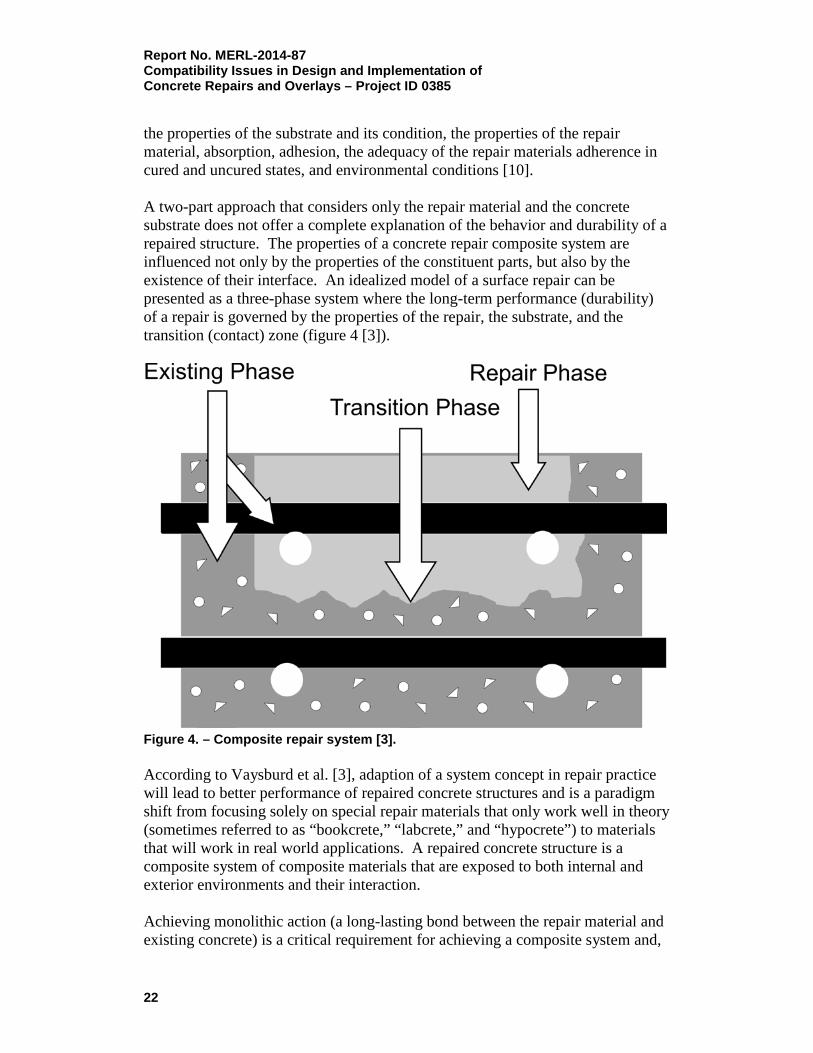
Report No. MERL-2014-87 Compatibility Issues in Design and Implementation of Concrete Repairs and Overlays – Project ID 0385 the properties of the substrate and its condition, the properties of the repair material, absorption, adhesion, the adequacy of the repair materials adherence in cured and uncured states, and environmental conditions [10]. A two-part approach that considers only the repair material and the concrete substrate does not offer a complete explanation of the behavior and durability of a repaired structure. The properties of a concrete repair composite system are influenced not only by the properties of the constituent parts, but also by the existence of their interface. An idealized model of a surface repair can be presented as a three-phase system where the long-term performance (durability) of a repair is governed by the properties of the repair, the substrate, and the transition (contact) zone (figure 4 [3]).
Figure 4. – Composite repair system [3]. According to Vaysburd et al. [3], adaption of a system concept in repair practice will lead to better performance of repaired concrete structures and is a paradigm shift from focusing solely on special repair materials that only work well in theory (sometimes referred to as “bookcrete,” “labcrete,” and “hypocrete”) to materials that will work in real world applications. A repaired concrete structure is a composite system of composite materials that are exposed to both internal and exterior environments and their interaction. Achieving monolithic action (a long-lasting bond between the repair material and existing concrete) is a critical requirement for achieving a composite system and,
22

Report No. MERL-2014-87 Compatibility Issues in Design and Implementation of
Concrete Repairs and Overlays – Project ID 0385
thus, durable repairs. The character of the contact zone is a function of the properties of the substrate adherent, the properties of the repair adhesive, and the surface preparation. The bond at the interface between the two constituents, or phases, is likely to be subjected to considerable stresses from such things as volume changes, freeze-thaw cycles, the force of gravity, and sometimes impact and vibration. The stress conditions that develop at the bond line will vary considerably, depending on the type and use of the structure. For example, the bond on a bridge deck overlay may be subject to shear stress in conjunction with tensile or compressive stresses induced by shrinkage or thermal effects, as well as to compressive and shear stresses from service loads. Repairs that have bond lines in direct tension have the greatest dependence on bond strength. Repairs that are subject to shear stresses at the bond line are capable of stress resistance not only by bonding mechanisms, but also by aggregate interlock mechanisms, which add greatly to shear bond capacity. Environmental factors such as ambient temperature, moisture, wind, and solar radiation also play an important role. A detailed discussion and analysis of the bond and its formation are presented in section V of this report.
D. Concrete Repair Process
Many concrete repair projects are complex and include condition evaluation of existing structures, durability planning, engineering project objectives, detailed design, specifications, material selection, construction, and quality control. In addition, to help ensure success despite this complexity, repair projects should include an integrated systemic approach to properly address compatibility issues. The entire process of performing a concrete repair project (figure 5) encompasses the following important processes:
• Assessing the condition of existing structure (degree of deterioration or distress);
• Assessing the cause(s) of deterioration/distress;
• Establishing the nature and severity of the internal environment in the existing structure;
• Ascertaining the probable service life of the repaired structure;
• Establishing realistic design objectives;
• Selecting an appropriate repair system;
• Developing repair details and specifications;
• Implementing the repairs as specified.
23
Report No. MERL-2014-87 Compatibility Issues in Design and Implementation of Concrete Repairs and Overlays – Project ID 0385
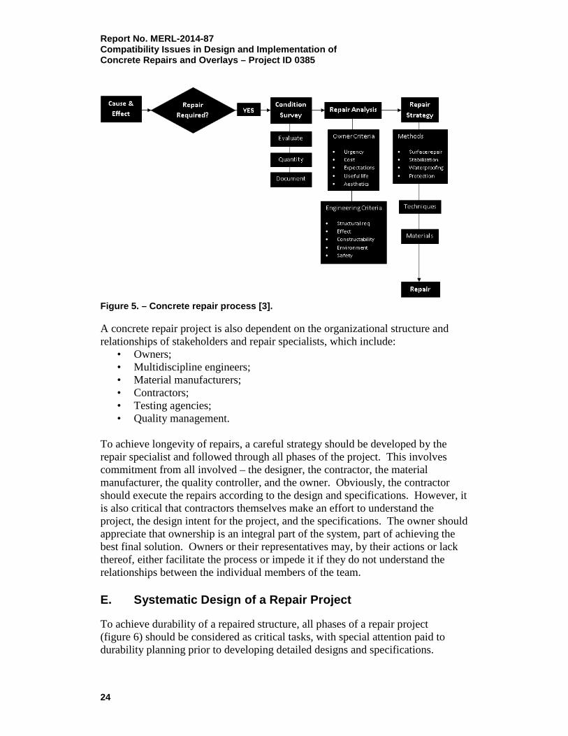
Figure 5. – Concrete repair process [3]. A concrete repair project is also dependent on the organizational structure and relationships of stakeholders and repair specialists, which include:
• Owners; • Multidiscipline engineers; • Material manufacturers; • Contractors; • Testing agencies; • Quality management.
To achieve longevity of repairs, a careful strategy should be developed by the repair specialist and followed through all phases of the project. This involves commitment from all involved – the designer, the contractor, the material manufacturer, the quality controller, and the owner. Obviously, the contractor should execute the repairs according to the design and specifications. However, it is also critical that contractors themselves make an effort to understand the project, the design intent for the project, and the specifications. The owner should appreciate that ownership is an integral part of the system, part of achieving the best final solution. Owners or their representatives may, by their actions or lack thereof, either facilitate the process or impede it if they do not understand the relationships between the individual members of the team.
E. Systematic Design of a Repair Project
To achieve durability of a repaired structure, all phases of a repair project (figure 6) should be considered as critical tasks, with special attention paid to durability planning prior to developing detailed designs and specifications.
24

Report No. MERL-2014-87 Compatibility Issues in Design and Implementation of
Concrete Repairs and Overlays – Project ID 0385
Figure 6. – Durability design project [5]. Durability planning must become a fundamental part of the repair design process and needs to be carried out before specifications and drawings are prepared. Durability planning expands on the process described above for the concrete repair process. There are six main stages for durability planning:
1. Assessment of the condition evaluation results;
2. Analysis of the consequences of continued deterioration to the structure, performance, structural risk, and economic issues;
3. Mathematical modeling and experience based considerations of future service life;
4. Establishment of performance requirements and project objectives;
5. Recommended remedial options (alternative solutions) to meet the project objectives; and
6. Life-cycle cost analysis.
The concept of effective durability planning is inextricably linked with the concept of future service life of the repaired structure and establishing the project
25

Report No. MERL-2014-87 Compatibility Issues in Design and Implementation of Concrete Repairs and Overlays – Project ID 0385 objective. The owner's strategy for maintenance also has a critical bearing on establishing project objectives. In addition, appropriate safety factors should be considered to allow for limitations of future service life prediction and unforeseen future developments [5]. Table 1 shows durability planning issues and approaches. Table 1. – Durability Planning Issues and Approach [5]
Function and Type of Structure Client’s Basic Needs Performance requirements Acceptable technical performance
Serviceability and safety criteria Importance of continuity of function during repair Accessibility Desirable service life Maintenance strategy
Loads Dead and live loading
Exterior environmental loads Water, temperature, and wind effects Aggressive agents and actions
Internal conditions Cracking, microcracking, other flaws Carbonation, chloride ion content, alkali-aggregate
reaction (AAR), sulfate attack, etc. Reinforcement corrosion section loss, deboning
Overall design approach Basic remediation strategy (do nothing and monitor, provide protection, repair, belt-and-suspender approach)
Evaluation of alternative solutions Costs Constructability and quality issues Known experience of performance
To ensure that the systematic engineering approach in design of repair projects meets the objectives of the designed service life and to ensure durability, the events that threaten future durability must be clearly identified. The repair professional must also understand how the structure reacts to durability mechanisms. This means that an aggressive environment and the possible deterioration mechanisms should be identified at the design stage. The true engineering design with an expected performance must then concentrate on two parallel activities:
• Ensuring sufficiently slow deterioration by resisting predicted internal and external environmental deterioration mechanisms;
• Providing satisfactory load-carrying capacity and safety under the expected loadings.
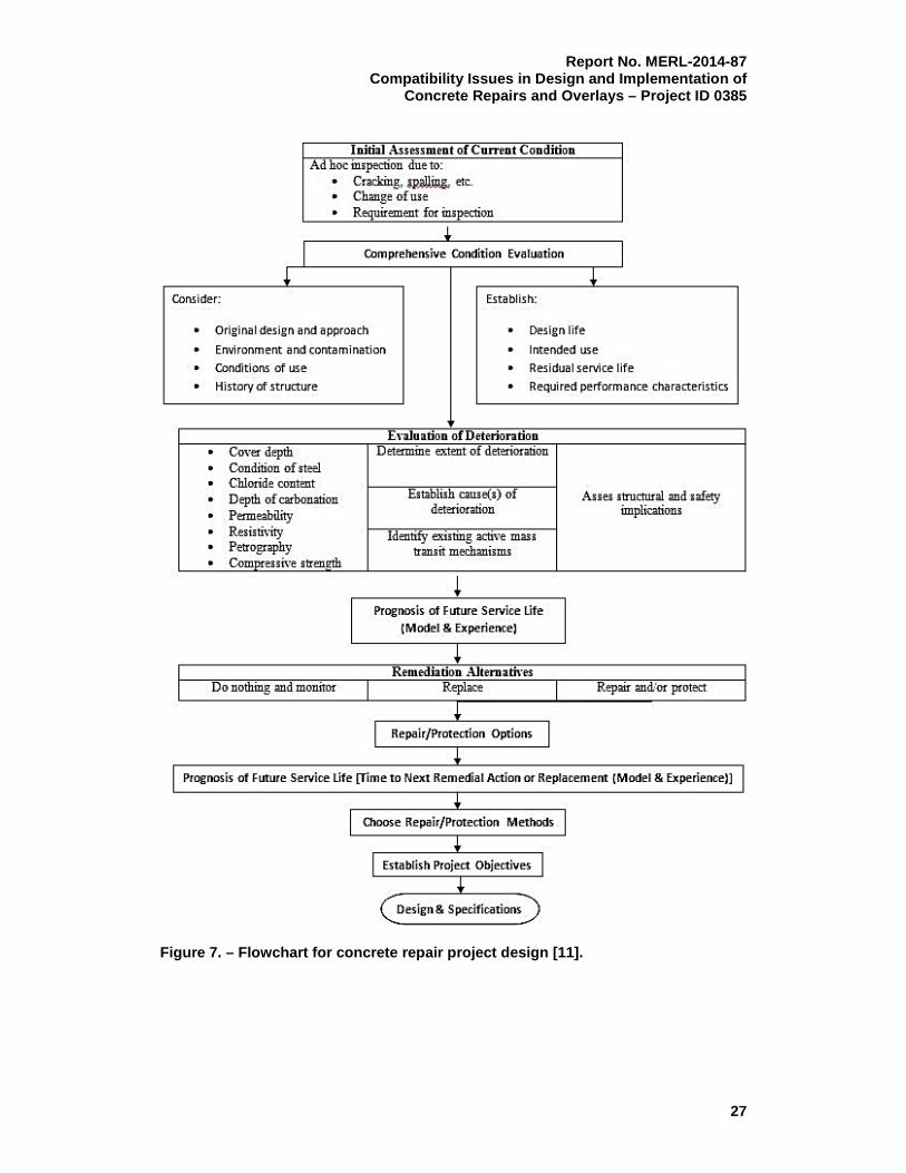
Figure 7 presents a flowchart for a concrete repair project design [11].
26
Report No. MERL-2014-87 Compatibility Issues in Design and Implementation of
Concrete Repairs and Overlays – Project ID 0385
Figure 7. – Flowchart for concrete repair project design [11].
27

Report No. MERL-2014-87 Compatibility Issues in Design and Implementation of Concrete Repairs and Overlays – Project ID 0385 F. Repair Versus New Construction as an Engineering Task
The engineering task of designing a manmade composite system of concrete repair is significantly more complex than new construction. Variability in almost everything is typical for repair jobs. Occasionally these variables cancel each other out; however, as a rule, they are likely to be cumulative. Table 2 presents some of the principal differences between repair and “new concrete” design. Table 2. – Principal Differences Between Repair and New Concrete Structure Construction [11]
Problem New Construction Repair
Durability Requirements
The concrete mixture for new construction is proportioned to meet durability requirements and protect embedded reinforcement from corrosion for the designed service life.
Repair of a concrete structure damaged due to poor durability (freeze-thaw, alkali-silica reaction (ASR), etc., or corrosion of embedded reinforcement is intended to stabilize or minimize further durability issues. In many cases, degradation may continue and possibly disrupt the repair system.
Service Life
The service life for ‘‘new concrete’’ structures can be predicted for many durability exposure conditions and for time to corrosion of reinforcing steel.
The goal of a quality repair is to prolong the time before the next remedial action is needed for as long as practically possible. A different level of reliability is associated with new construction in comparison with concrete repair. In many cases, when repairs are made, deterioration is extensive. With the repair, it may not be possible to fully restore the structure back to its initial stage.
Cracking (dimensional compatibility)
It is easier to control cracking in newly constructed structures.
Restrained contraction of repair materials, caused by the restraint from the bond to the existing substrate, can lead to cracking, debonding, and, finally, to continued or further degradation and/or corrosion of reinforcing steel.
Electrochemical Compatibility
In “new” construction, all of the reinforcement is surrounded by a relatively uniform internal environment.
In repaired structures, the electrically continuous reinforcing system is affected by the simultaneous existence of diverse environmental conditions. By coating the reinforcing bar, and therefore insulating it, a region of high differential in electro-potential is established at the borderline between old and new. At the point where the coating is stopped, a point of potential major corrosion is established. Upon completion of the repair, a mass of new material, which is very different from the surrounding mass of undisturbed material, is created. In doing so, a potentially more corrosive situation may be set up than the one we started with.
28
Report No. MERL-2014-87 Compatibility Issues in Design and Implementation of
Concrete Repairs and Overlays – Project ID 0385
Problem New Construction Repair
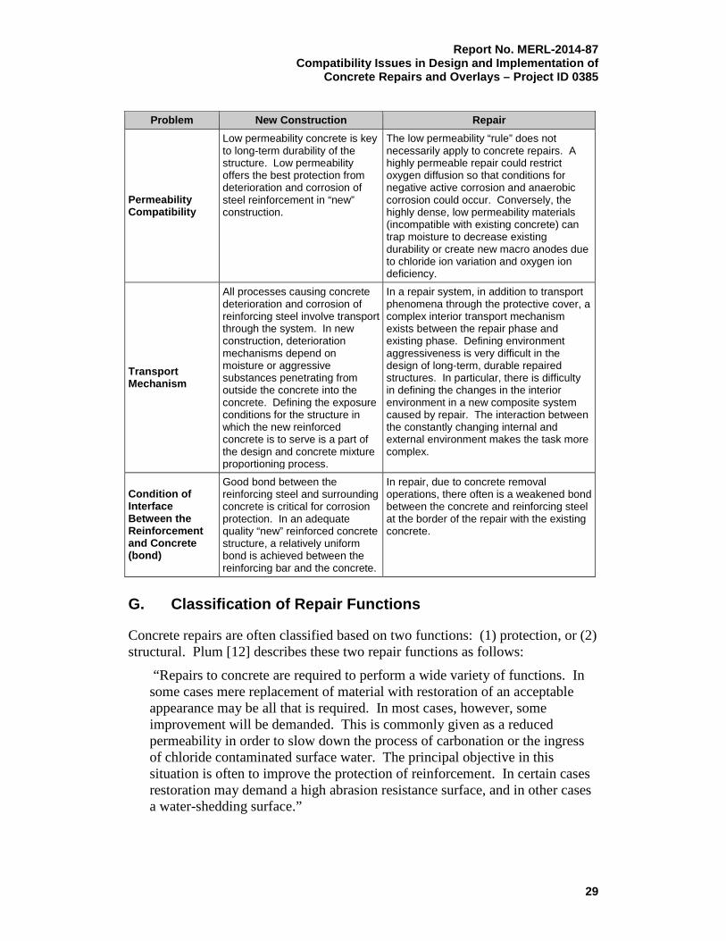
Permeability Compatibility
Low permeability concrete is key to long-term durability of the structure. Low permeability offers the best protection from deterioration and corrosion of steel reinforcement in “new” construction.
The low permeability “rule” does not necessarily apply to concrete repairs. A highly permeable repair could restrict oxygen diffusion so that conditions for negative active corrosion and anaerobic corrosion could occur. Conversely, the highly dense, low permeability materials (incompatible with existing concrete) can trap moisture to decrease existing durability or create new macro anodes due to chloride ion variation and oxygen ion deficiency.
Transport Mechanism
All processes causing concrete deterioration and corrosion of reinforcing steel involve transport through the system. In new construction, deterioration mechanisms depend on moisture or aggressive substances penetrating from outside the concrete into the concrete. Defining the exposure conditions for the structure in which the new reinforced concrete is to serve is a part of the design and concrete mixture proportioning process.
In a repair system, in addition to transport phenomena through the protective cover, a complex interior transport mechanism exists between the repair phase and existing phase. Defining environment aggressiveness is very difficult in the design of long-term, durable repaired structures. In particular, there is difficulty in defining the changes in the interior environment in a new composite system caused by repair. The interaction between the constantly changing internal and external environment makes the task more complex.
Condition of Interface Between the Reinforcement and Concrete (bond)
Good bond between the reinforcing steel and surrounding concrete is critical for corrosion protection. In an adequate quality “new” reinforced concrete structure, a relatively uniform bond is achieved between the reinforcing bar and the concrete.
In repair, due to concrete removal operations, there often is a weakened bond between the concrete and reinforcing steel at the border of the repair with the existing concrete.
G. Classification of Repair Functions
Concrete repairs are often classified based on two functions: (1) protection, or (2) structural. Plum [12] describes these two repair functions as follows:
“Repairs to concrete are required to perform a wide variety of functions. In some cases mere replacement of material with restoration of an acceptable appearance may be all that is required. In most cases, however, some improvement will be demanded. This is commonly given as a reduced permeability in order to slow down the process of carbonation or the ingress of chloride contaminated surface water. The principal objective in this situation is often to improve the protection of reinforcement. In certain cases restoration may demand a high abrasion resistance surface, and in other cases a water-shedding surface.”
29

Report No. MERL-2014-87 Compatibility Issues in Design and Implementation of Concrete Repairs and Overlays – Project ID 0385 Protection and appearance are sometimes closely related. According to Emmons et al. [7], each area of repair for a concrete structure condition requires the designer to clearly understand the objective of the repair. Figure 8 shows a diagram of the performance requirements.
Figure 8. – Performance requirements [7]. The process of repair design and specification consists of determining the exact function of the repair so that the correct repair process can be specified. A concrete repair must replace damaged concrete. Repair materials must be installed and cured properly. Stresses in the repair system must be within the capacity of the new and existing materials; otherwise, failure may occur. After the material reaches the specified strength, loads can be allowed on the member.
30
Report No. MERL-2014-87 Compatibility Issues in Design and Implementation of
Concrete Repairs and Overlays – Project ID 0385
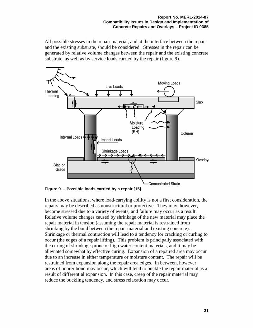
All possible stresses in the repair material, and at the interface between the repair and the existing substrate, should be considered. Stresses in the repair can be generated by relative volume changes between the repair and the existing concrete substrate, as well as by service loads carried by the repair (figure 9).
Figure 9. – Possible loads carried by a repair [15]. In the above situations, where load-carrying ability is not a first consideration, the repairs may be described as nonstructural or protective. They may, however, become stressed due to a variety of events, and failure may occur as a result. Relative volume changes caused by shrinkage of the new material may place the repair material in tension (assuming the repair material is restrained from shrinking by the bond between the repair material and existing concrete). Shrinkage or thermal contraction will lead to a tendency for cracking or curling to occur (the edges of a repair lifting). This problem is principally associated with the curing of shrinkage-prone or high water content materials, and it may be alleviated somewhat by effective curing. Expansion of a repaired area may occur due to an increase in either temperature or moisture content. The repair will be restrained from expansion along the repair area edges. In between, however, areas of poorer bond may occur, which will tend to buckle the repair material as a result of differential expansion. In this case, creep of the repair material may reduce the buckling tendency, and stress relaxation may occur.
31

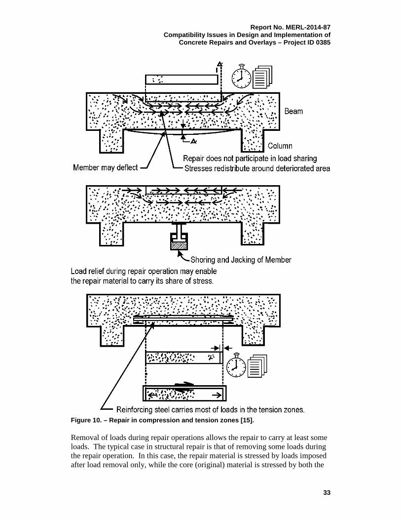
Report No. MERL-2014-87 Compatibility Issues in Design and Implementation of Concrete Repairs and Overlays – Project ID 0385 By contrast, repairs to columns and beams will require the removal of load bearing concrete and concrete replacement with material that is capable of carrying the same load. Load relief from members is typically provided with temporary shoring and jacking. These repairs are described as structural and are clearly different in their requirements from repairs that are protective. In most cases, the desirable condition is to have the repair in a compressive state so that compressive loads can be carried. In cases where the original member was overdesigned, and in tension zones of beams, some relief of this criterion may be permissible. However, in general, all compression or load bearing concrete must be fully replaced, and the replacement must be load bearing. For a structural repair, the load remaining on the structure during repair operations must be defined. In many situations, it is difficult to achieve load carrying in a surface repair. The behavior of small surface repairs introduced to restore durability to a member is likely to be considerably influenced by the deformation of the surrounding steel and concrete. Here, the strain capacity of the repair material, rather than its ability to carry stress, is of prime importance. With larger structural repairs where a contribution to member stiffness is required, the repair must possess properties that will both ensure that it stays in place to protect the steel and will also resist stress for the remaining life of the structure. In both cases, the effect of the load on the repair is important [13]. Where a significant amount of material in the compression zone has been lost, loads redistribute to the remaining sound concrete. Significant section loss may result in overstress and excessive deflection. For example, deterioration in compression zones of flexural members results in redistribution of stress to other parts of the member. If all loads are left on the structure during the repair operation, then in theory, the repair material may never become loaded. This “no-load relief” case rarely occurs; but when it does, compressive stress in the repair of, for example, a column only results when creep or other deformation of the core (original) material takes place. In this case, however, if the imposed load were removed at a later date, tensile strains could be induced in the repair material. Deterioration in tension zones of flexural members exposes tensile steel reinforcement. Most, if not all, tension is carried by the reinforcing steel. If the steel has lost section in the corrosion process, excessive deflections may result. During the repair process, relief of tension loads is desirable and is usually accomplished by temporary support of the affected member. Active shoring (shoring that carries the acting dead and live loads of the member) will allow for repair of damaged reinforcing bars at a low stress level. After completion of repairs and removal of shoring, the repaired reinforcement will be able to carry the original loads (figure 10).
32
Report No. MERL-2014-87 Compatibility Issues in Design and Implementation of
Concrete Repairs and Overlays – Project ID 0385
Figure 10. – Repair in compression and tension zones [15]. Removal of loads during repair operations allows the repair to carry at least some loads. The typical case in structural repair is that of removing some loads during the repair operation. In this case, the repair material is stressed by loads imposed after load removal only, while the core (original) material is stressed by both the
33

Report No. MERL-2014-87 Compatibility Issues in Design and Implementation of Concrete Repairs and Overlays – Project ID 0385 dead and the superimposed loads. Changes in stress distribution may occur slowly with time due to creep and thermal or moisture movements of both materials. If creep of the repair material is high, compared with that of the core concrete, there will be a tendency for it to shed its load. The reverse situation (which is unusual) would result in it gaining load from the core concrete. A less typical case is when all loads are removed by jacking or removal of structural elements during the repair operation, so that the repaired elements are essentially unstressed during the repair operation. Clearly, this case is less common due to the cost of load removal. On replacing the load, the core concrete and the repair material will be stressed to levels that depend on the cross-sectional areas and the properties of both materials. Ultimate stresses in the repair materials and core concrete will be dependent on the effects of creep and other movements. Again, the action of creep will, in general, be to transfer load away from the repair (high creep) and into the core (low creep). From this example, we can conclude that creep is a property of great significance for structural repair. By contrast, protective repairs have no stress carrying requirement. Analysis may be performed to estimate the action of the repair material, both under the linear elastic and the ultimate conditions. From such studies, relationships may be developed which relate the area ratio (the proportion of compression area being replaced) to the repair function (the proportion of load carried by the repair material). Additional analysis can be performed relating the bond strength with other material properties and repair dimensions. The purpose of this analysis is to account for the expansion, which is estimated to occur in the repair material, due to thermal and moisture changes. In normal circumstances, thermal expansions will not exceed 1000 microstrains, but moisture movements may lead to much higher expansions. Well-formulated materials can expand 2,000 microstrain upon saturation, and poorly formulated materials can expand by as much as 20,000 microstrains. A low expansion material may be expected to have 2,000 microstrains or less; for this, a lower bond strength (1 Newton per square millimeter [N/mm2] – 145 pounds per square inch [lb/in2]) will suffice. Increased creep reduces this requirement still further. A higher expansion material, however, if coupled with a high elastic modulus, would need a better bond strength (3 N/mm2 – 440 lb/in2). This level of bond can be difficult to achieve under field conditions. In addition to understanding the loads that a structure or part of a structure may experience, it is also very important to understand that the type and level of stress in the material affect, to a great extent, its permeability and the rate of its interaction with the environment. Compression or tension of repair materials in their elastic range induces reversible changes in the size of pores, capillaries, and microcracks of the material structure. In the elastoplastic region, strain affects not
34
Report No. MERL-2014-87 Compatibility Issues in Design and Implementation of
Concrete Repairs and Overlays – Project ID 0385
only the macro structure, but also the microstructure of materials. Lattice defects in the hardened cementitious matrix and tips of microcracks get overstressed, so that microcracks propagate further, and some join, thereby increasing the permeability of the material. Tension strains, in all cases, increase the permeability of the repair and reduce its protective power and resistance to ingress of foreign materials. The state of stress influences the resistance of the repaired structure to attack by various aggressive environments. Industrial environments may present different combinations of loading and corrosion. The loading (sign and level of stress, duration of load) and the environmental influence (type and concentration of the active substance, ambient temperature, and duration of attack) are of prime importance for the long-term durability of repaired concrete structures [14].
III. Compatibility Factors and Properties Concrete repair is a three-phase composite system of multiphase synthetic composite materials and, as such, is extremely complex. The composite repair system is formed as a result of setting and hardening of a semi-liquid substance (repair material) that is placed on the surface of a substance in a solid state (existing concrete). Compatibility of these disparate phases is critical to achieve durable repairs. Emmons and Vaysburd [16] stated that the term “compatibility” has become very popular in various fields, as well as in concrete repair. We do not normally adequately address compatibility in design projects, nor are the primary factors affecting durability properly addressed in specifications. There are four reasons why this is usually not done:
1. Lack of a clear definition of compatibility in concrete repair;
2. Misleading guidance on achieving compatibility in concrete repair;
3. Limited scientific guidance and knowledge in addressing some of the compatibility aspects;
4. Lack of reliable performance test methods for evaluating different aspects of compatibility.
Many repair methods currently employed in the concrete repair field have been derived, probably for as long as concrete has been used, from observations and through trial and error, with both good and bad results. As Bronowski [17] stated, “Good prediction is one which defines its area of uncertainty; a bad prediction ignores it.” This applies particularly to the design and specifications for repairs of concrete structures built in different environments. Theoretically, the probability of a repair to withstand the complex forces and elements acting on it can be
35

Report No. MERL-2014-87 Compatibility Issues in Design and Implementation of Concrete Repairs and Overlays – Project ID 0385 predicted. Virtually always, these predictions are based on insufficient information. There is not enough reliable information on repair systems and their performance under stresses from volume changes and the environment. Currently, there are not enough tools available to help the concrete repair professional consistently design a durable repair. The poor performance of repairs means that the design and construction of concrete repairs cannot be left to older methods, which many times are based on guesses [18]. There is a need to inform concrete repair professionals about material compatibility issues, which we know are critical to the performance and durability of repaired concrete structures [2].
A. Definition of Compatibility in Concrete Repair
The Webster’s Dictionary defines compatibility as: “The capacity of two or more entities to combine or remain together without undesirable after effects: mutual tolerance.” When discussing compatibility, many concrete repair “experts” proclaim that repairing “like with like” offers a durable solution, and that for the repair material to be compatible with existing concrete it should have “composition and properties similar to the substrate concrete.” While such a concept may be applicable in some simple cases, it lacks not only a technical basis, but also lacks common sense in many cases [8]. Designs that promote repairing “like with like” are often nonsensical. To begin with, it is impossible to match properties of the semi-liquid adhesive (repair material mixture) with the matured solid adherent (existing concrete) [11]. Further, the concrete repair professional, faced with such inappropriate guidance, may opt for materials having properties as close to those of the substrate concrete as possible. Very often, however, the substrate concrete’s poor quality is the cause of the problem. The poor quality of the original concrete can lead to extensive shrinkage cracking, high porosity, ASR, sulfate attack, etc. The temptation to seek parity of properties of the repair materials and base concrete is strong, but attempts to avoid “mismatch” ignore important aspects of material compatibility. Repairs to concrete structures are carried out by applying a repair material to a prepared base concrete. A wide range of materials are currently used in the repair of concrete. The most obvious material is a similar concrete, but true similarity can be very difficult to achieve in reality. Often, repairs are applied in thin sections, resulting in the use of only fine aggregates in the repair material. Mixture consistency can vary from free-flowing to stiff. Cements, aggregates, and water contents of the repairs will inevitably be different from the original concrete, even if no enhancement of properties is desired.
36
Report No. MERL-2014-87 Compatibility Issues in Design and Implementation of
Concrete Repairs and Overlays – Project ID 0385
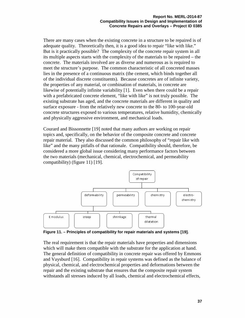
There are many cases when the existing concrete in a structure to be repaired is of adequate quality. Theoretically then, it is a good idea to repair “like with like.” But is it practically possible? The complexity of the concrete repair system in all its multiple aspects starts with the complexity of the materials to be repaired – the concrete. The materials involved are as diverse and numerous as is required to meet the structure’s purpose. The common characteristic of all concreted masses lies in the presence of a continuous matrix (the cement, which binds together all of the individual discrete constituents). Because concretes are of infinite variety, the properties of any material, or combination of materials, in concrete are likewise of potentially infinite variability [1]. Even when there could be a repair with a prefabricated concrete element, “like with like” is not truly possible. The existing substrate has aged, and the concrete materials are different in quality and surface exposure - from the relatively new concrete to the 80- to 100-year-old concrete structures exposed to various temperatures, relative humidity, chemically and physically aggressive environment, and mechanical loads. Courard and Bissonnette [19] noted that many authors are working on repair topics and, specifically, on the behavior of the composite concrete and concrete repair material. They also discussed the common philosophy of “repair like with like” and the many pitfalls of that rationale. Compatibility should, therefore, be considered a more global issue considering many performance factors between the two materials (mechanical, chemical, electrochemical, and permeability compatibility) (figure 11) [19].
Figure 11. – Principles of compatibility for repair materials and systems [19]. The real requirement is that the repair materials have properties and dimensions which will make them compatible with the substrate for the application at hand. The general definition of compatibility in concrete repair was offered by Emmons and Vaysburd [16]. Compatibility in repair systems was defined as the balance of physical, chemical, and electrochemical properties and deformations between the repair and the existing substrate that ensures that the composite repair system withstands all stresses induced by all loads, chemical and electrochemical effects,
37

Report No. MERL-2014-87 Compatibility Issues in Design and Implementation of Concrete Repairs and Overlays – Project ID 0385 and restrained volume changes without distress and deterioration over a designed period of time [16, 18]. It is clear from the above examination of structural repairs that compatibility is defined by the ability of the material to maintain a given strain and, hence, carry the correct stress. In protective repairs, the definition concentrates on what happens at the interface, and compatibility becomes maintaining the geometry of the interface. Compatibility for a structural repair may be defined as that combination of properties and dimensions that ensures that the repair carries its design load, allowing for any changes that may take place with time and the environment. Compatibility for a protective repair may be defined as that arrangement of dimensions and properties of the materials that ensures that interface bond strength is not exceeded. Clearly, these definitions involve knowledge of the repair dimensions, in conjunction with a variety of material properties of both the repair and the substrate. The substrate properties include failure stress and failure strain, and the repair properties are principally elastic modulus and creep. As can be seen from the foregoing discussion, compatibility is a complex subject with many different facets. Figure 12 [3] presents the properties and factors to be addressed in compatibility analysis.
Figure 12. – Concrete repair: A composite system [3]
38

Report No. MERL-2014-87 Compatibility Issues in Design and Implementation of
Concrete Repairs and Overlays – Project ID 0385
B. Dimensional Compatibility
One of the most important compatibility requirements is dimensional (deformational) compatibility of repair materials with the existing substrate. The essence of dimensional compatibility can be stated as follows:
• Shrinkage of the repair material relative to the substrate;
• Differences in the rate of thermal expansion or contraction of the repair and substrate materials;
• Differences in modulus of elasticity, which may cause unequal load distribution and strains, resulting in interface stresses;
• Differences in creep;
• Relative fatigue performance of the phases in the composite system.
The listed differences may result in initial tensile stresses that either crack the repair material or cause debonding at the repair substrate interface (the transition zone). Both of these will negatively affect durability and load carrying capacity of the repaired structure [2, 16]. Hewlett defined the phenomenon of dimensional compatibility as “stable interfacial coexistence” [20].
1. Components of Dimensional Compatibility
Restrained contraction of repair materials, with restraint from the bond of the repair material to the existing concrete substrate, significantly increases the complexity of repair projects, as compared to the complexity of new construction. Volume changes cause the contractions that often result in cracking, which is a result of dimensional incompatibility. The chemical and mineralogical composition of a repair material, its “microstructural engineering” [21], are important, but they are only part of the topic. A material’s response to volume changes, such as shrinkage and creep, and resulting resistance to cracking, its “macrostructural engineering,” is of paramount importance. Those material properties which influence dimensional compatibility include shrinkage, thermal expansion, modulus of elasticity, and creep. Many materials change volume with moisture and temperature changes. Tensile stresses are induced in one material, compressive stresses are induced in the other; as a result, shear will occur at the interface. Similar stresses will result from the differential thermal movement and moduli of elasticity (figure 13) [18]. Vaysburd et al. [22] stated that a design engineer with a poor understanding of dimensional compatibility may specify repair materials with properties that match, as closely as possible, those of the existing substrate concrete. As discussed earlier, the temptation is strong to avoid mismatched properties between the repair material and substrate. However, this clearly contradicts the general definition of compatibility in concrete repair. In some instances, it is appropriate
39

Report No. MERL-2014-87 Compatibility Issues in Design and Implementation of Concrete Repairs and Overlays – Project ID 0385 to select repair materials with properties that do not match the material properties of the substrate in order to meet dimensional compatibility requirements.
Figure 13. – Volume change effects on repair [adapted from 15]. The lack of understanding of the nature of dimensional compatibility is frequently the source of many failures in practice. It can lead to excluding some repair materials that may work much better than materials with similar properties to the substrate. The authors wish to emphasize the need for a clear appreciation of dimensional compatibility in concrete repair and, in this context, of those material properties which may provide the key to successful and durable repairs; for example, the use of polymer-based repair materials to repair concrete. When considering the use of any polymer-based repair material in concrete repair applications, certain aspects of these materials should be analyzed and understood:
40

Report No. MERL-2014-87 Compatibility Issues in Design and Implementation of
Concrete Repairs and Overlays – Project ID 0385
• Polymer-based materials cover an extremely broad range of chemical/physical types;
• Their physical properties are uniquely different to those of concrete (i.e., there is a basic mismatch);
• To use them in intimate contact with an existing concrete substrate, the response of the composite repair system (not the isolated repair material) needs to be assessed;
• The material properties are sensitive to the effects of relatively small temperature changes and are also time dependent;
• Hardened properties can be markedly affected by the environment in which the material is applied and cured.
An integral part of this method is the assessment of the likely consequences of any “mismatch” of properties (e.g., thermal coefficient of expansion, modulus of elasticity and creep, etc.). For many applications, success depends on recognizing and overcoming a potentially damaging mismatch, either by use of an appropriate polymer type or by appropriate application procedures. A point which is often overlooked is that the mismatch due to the characteristics of polymers can often result in beneficial stress relaxation due to high creep of the material. That may allow potentially destructive stresses, which may occur due to differences in shrinkage and volume changes due to temperature cycling during service, to dissipate. The primary importance of dimensional compatibility properties such as shrinkage, creep, and elastic modulus in concrete repair is whether or not their interaction would lead to cracking and/or debonding. Different repair methods and materials are currently used to repair damage in deteriorated structures. The basic mechanical and physical interaction of such products, and the substrate on which they are placed, needs to be established before selecting a suitable repair material. Several authors [23, 24, 25, 26] have highlighted the potential importance of property mismatch between patch repair materials and the reinforced concrete substrate. A two-component system, such as a polymer concrete (PC) repair material on a portland cement concrete (CC) substrate, is produced in a typical repair situation using polymer materials. Lack of understanding of the PC–CC interaction is frequently the source of failure in practice. The compatibility of PC–CC systems is the main problem considered in a study by the National Institute of Standards and Technology (NIST) [27]. During a repair’s service life, incompatibilities in the form of differing strength and moduli of elasticity between repair and substrate concrete can create strains and stress concentration. Also, shrinkage of repair materials can reduce longer-term structural efficiency by either causing tensile strain in the repair and/or by cracking at the repair/substrate interface. Creep of the repair material under sustained stress can also reduce the load sharing capacity of the repair.
41
Report No. MERL-2014-87 Compatibility Issues in Design and Implementation of Concrete Repairs and Overlays – Project ID 0385 Mehta and Monteiro [28] introduced the concept of “extensibility of materials,” which is directly related to dimensional compatibility between repair materials and concrete substrates. The magnitude of shrinkage strains is a dominant factor, but not the only factor, that affects the cracking of the repair material. The other important factors are:
• Restraint – Restraint to volume changes limits changes in dimension, causing stresses in repair materials and possible cracking;
• Modulus of elasticity – The lower the modulus of elasticity, the lower the amount of the induced elastic tensile stress for a given magnitude of shrinkage;
• Creep – The higher the creep, the higher the amount of stress relaxation, and the lower the amount of the net tensile stress;
• Tensile strength – The higher the tensile strength, the lower the risk that the tensile stress will exceed the strength, thus cracking the material.
The combination of properties that is desirable to reduce cracking in cement-based material can be described by the term “extensibility,” which is an appropriate combination of low elastic modulus, high creep, low shrinkage, and high tensile strength. Cement-based materials are said to have a high degree of extensibility when they can be subjected to deformations without cracking. Cement-based materials should undergo not only less shrinkage, but also should have a high degree of extensibility. Unfortunately, the tensile strength of cement-based materials is low and cannot be increased substantially. Therefore, the only rational way to increase a materials extensibility and minimize the risk of cracking is by using materials with a low modulus of elasticity, high creep, and, perhaps most importantly, by reducing shrinkage. Materials must develop tensile strength faster than tensile stresses develop due to shrinkage or else cracking occurs.
2. Tensile Strength
Cement-based materials have low tensile strength relative to their compressive strength, so they can crack fairly easily when their tensile stress exceeds their tensile strength. Knowledge of the magnitude of the tensile strength of a material is therefore important. It is a direct function of the bond strength on the aggregate-matrix interface, of the tensile strength of the cement paste, and of the frequency and development of local defects existing in the material itself. Moreover, there are many situations in which tensile strength is neglected but cracking is undesirable. This frequently happens with concrete repairs when cracking occurs after the tensile strength of the repair material has been exceeded. Concrete is from 10 to 20 times stronger in compression than in tension; hence, its principal load-bearing function in structures is to carry compressive stresses. Steel reinforcement or prestressing tendons are used to carry tensile loads. For this
42

Report No. MERL-2014-87 Compatibility Issues in Design and Implementation of
Concrete Repairs and Overlays – Project ID 0385
reason, most investigations into the mechanical properties of concrete have focused on determining compressive properties and compressive stresses. However, increasing emphasis on economy in design requires that the designer be more knowledgeable about the tensile properties of concrete. In particular, the designer must understand that the onset and prediction of cracking in the tensile zone of reinforced concrete members, which has direct relevance for the design of water-retaining structures or structures with specific durability requirements, are dependent upon the tensile behavior. In addition, the designer must realize that failure in shear in reinforced concrete structures occurs by diagonal tension cracking; therefore, shear strength is directly related to tensile strength [29]. The importance of tensile properties can be emphasized by the conclusion of Hsu and Slate [30]:
“ . . .tensile strength of concrete is a quality different in nature from the compressive strength…. Therefore the tensile strength of bond, paste, mortar, and concrete deserves careful and thorough study by itself, separate from compressive strength.”
Following is a very interesting discussion concerning the criticality of tensile strength offered by Tassios [31]:
“It is sometimes surprising to observe that designers tend to have a rather hazy idea of the basic material they are supposed to design; they merely recognize “classes” of concrete according to its compressive strength, as measured from some artificially made and artificially cured specimens. Design codes seemed to encourage this apparently narrow-minded attitude, by ‘translating’ every performance of concrete into its compressive strength. This practice occasionally produced some deficient designs or even gross errors. This was for instance the case, some decades ago, of the fanatic reduction of w/c (water to cement) ration to such an extent as to produce strong but permeable concrete; their high compressive strength was accompanied by remarkably low tensile strength and low water tightness, with detrimental consequences to serviceability. The same dichotomy between “analysis” and “technology” is portrayed in the pseudo-scientific question we frequently put: “Are these cracks due to stresses or are they just due to inadequate curing?” It is however clear to everyone that stresses are always the cause of cracking or discontinuities produced in materials. Stresses are induced by several actions, such as:
• loads;
• differential settlements;
• restraint strains, due to thermal or drying shrinkage;
• local swellings, (e.g. iron oxides due to steel corrosion, ettringite formation, etc.).
43
Report No. MERL-2014-87 Compatibility Issues in Design and Implementation of Concrete Repairs and Overlays – Project ID 0385
In all these cases, the basic mechanism for cracking is the exceeding of extensibility of concrete when it is subjected to a field of tensile stress. Here again, the need for a unification of approach becomes apparent. Situations are presented where a broader understanding of concrete technology is needed by a designer in order to better serve their purpose. Modern designers are now obliged to specialize themselves in concrete technology. Otherwise, a formalistic application of durability provisions (without a deeper knowledge of diffusion, permeability, pathological mechanisms, and scientifically based remedies), may lead to gross errors and threaten the future of concrete structures.”
The term “tensile strength” has no absolute meaning, but it must be expressed in terms of the specific test procedure used. Three kinds of tests have been used for cementitious materials testing: the direct tension test, and two indirect tests (the beam test and the splitting tension test). The direct tension test is difficult to perform because of the difficulty in ensuring that the load is truly axial. In a ductile material, some eccentricity will not have much effect on tensile strength. On the other hand, in brittle cementitious materials, there is relatively little redistribution of stress. Consequently, the test gives an underestimate of true tensile strength. However, Concrete Research Division (CRD) C 164, Standard Test for Direct Tensile Strength Test [32], when properly conducted, gives the most realistic results. In spite of their simplicity, the indirect tests fail to represent the stresses developed within axially loaded tension specimens; consequently, the values of the corresponding strengths differ from the pure tensile strength values. The results from the beam (modulus of rupture) test and the splitting test are both known to overestimate the tensile strength of the material. Data by Price [33] demonstrates that beam tests tend to overestimate the tensile strength of concrete by 50 to 100 percent. In the last several years, owing to higher-quality adhesives, new capabilities have been created which allow the tensile stress to be established on axially loaded tensile test specimens. Metallic shims are attached to the ends of material specimens to simplify the fastening and centering of the test specimen ends between the jaws of the testing machine. As a result of this development, many laboratories now use axially loaded test specimens in tension to establish tensile strengths and strains. This type of loading reflects the real stress and strain conditions. The easiest way to improve the resistance of cementitious materials to cracking would be to achieve substantially higher tensile strength. While higher tensile strengths would improve resistance to cracking, there are limits to what can
44
Report No. MERL-2014-87 Compatibility Issues in Design and Implementation of
Concrete Repairs and Overlays – Project ID 0385
be achieved with cement-based materials. The tensile strength, determined in accordance with CRD-C 164, should be a minimum of 400 lb/in2 (2.8 Mega-Pascals [MPa]), a tensile strength that would be expected for conventional concrete with a compressive strength of approximately 5,000 lb/in2 (35 MPa). However, because it is virtually impossible to substantially increase the tensile capacity of a cement-based material, methods to reduce tensile stresses to minimize cracking need to be considered.
3. Shrinkage
The size and shape of a concrete repair have a considerable effect on the rate and total amount of shrinkage. In repairs, differential volume changes occur, with the largest shrinkage found at and near the surface. If the cement-based repair material is free to shrink (free shrinkage), it just becomes shorter, without any defects or distress. However, this is not the case with a concrete composite repair system. Shrinkage of hardened cement-based materials, when restrained by bond to the substrate, produces tensile stresses. Since the tensile strength capacity of the material is very low, it usually cracks. Cracks are bad for many reasons, but, more importantly, external cracks, interlinking with internal voids and microcracks that are always present in cement-based materials, make it possible for water and other harmful chemicals and gases to penetrate with relative ease into the interior of concrete. High internal stresses may result in cracking, loss of load carrying capacity, delamination, and premature repair failure. Tensile stresses begin to accumulate in the repair material when shrinkage begins. As shrinkage stresses accumulate, the repair material resists cracking until the stress exceeds the tensile capacity of the repair material. Repair distress is triggered by the stress concentrations at the interface, a region where the probability of failure is as high as in the material itself. The load-carrying capacity of the repair material does not come into play when the repair material fails to fill the cavity as designed, because of the effects of shrinkage. Figure 14 shows the stress distribution around a new repair material that does not carry its part of the load [34].
a. Types of Shrinkage Volume stability refers to initial and long-term changes in the linear dimensions or volume of the repair material after placement. Volume stability properties affect the compatibility of the repair material with the substrate concrete. The substrate concrete is usually relatively stable, with minimal residual creep and shrinkage deformations; however, the substrate concrete may experience some volume instability for various reasons, including seasonal environmental changes such as thermal expansion and contraction.
45

Report No. MERL-2014-87 Compatibility Issues in Design and Implementation of Concrete Repairs and Overlays – Project ID 0385
Figure 14. – The effects of shrinkage [34]. Any shrinkage or expansion of the repair material should occur before the repair material has reached its final set (when creep is high), or it should be accommodated in some manner in the repair design, such as using joints, curing, avoidance of reentrant corners, and avoidance of high length-width ratio configurations (ACI 546.3R [35]). Cement-based materials are subject to several causes of volume change during their service life. From the point of view of their relative significance, many believe that, under conditions of restraint, the volume changes associated with shrinkage are the most deleterious. Frequently, the first form of shrinkage a concrete mixture can experience is plastic shrinkage. Plastic shrinkage occurs while the concrete is still in a plastic state, and water evaporates from the surface faster that it is replaced by bleed water. The overall loss of moisture at the surface causes shrinkage and can lead to cracking. Drying shrinkage occurs from the loss of moisture from hardened concrete. Among the more important factors that influence drying shrinkage of concrete are the content of cement paste and its quality (i.e., water-cement ratio and degree of hydration), the elastic modulus of the aggregate, the characteristics and amounts
46

Report No. MERL-2014-87 Compatibility Issues in Design and Implementation of
Concrete Repairs and Overlays – Project ID 0385
of admixtures used, the time and the relative humidity of exposure, the size and shape of the concrete mass, and the amount and distribution of reinforcing steel. Drying shrinkage starts at the surface of the concrete, at a surface exposed to unsaturated air or a dry substrate, inducing tensile forces. The tensile forces in the concrete near the surface are balanced by compressive forces in the interior, which are relieved as the exterior part of the concrete undergoes cracking or as creep takes place [36]. Drying shrinkage is best known because of its negative effects on durability as a result of the numerous cracks it can produce. Commonly, water is lost by evaporation to the atmosphere, but the loss can also occur by suction of underlying dry concrete or soil. For many concrete mixtures, and typically for those with a w/c over 0.42, it is the largest source of shrinkage Autogenous shrinkage occurs without loss of moisture to the surrounding environment but, rather, as a consequence of ongoing hydration of cement. Autogenous shrinkage develops isotropically within the concrete mass, provided that the distribution of the original cement grains is uniform in space. Because this type of shrinkage occurs within a concrete mass (without direct contact with the surrounding environment), it is also often called contraction or self-desiccation shrinkage. Occasionally, the term “chemical shrinkage” is used because it is related to the hydration process. In addition, the volume of the hydration products is smaller than the initial volume of the water and cement. This type of shrinkage is relatively larger than drying shrinkage for concrete mixtures with w/c ratios less than about 0.42. Shrinkage deformation also occurs as a result of a decrease in the temperature of concrete from its temperature at the time of setting, or soon thereafter, when the overall dimensions of a concrete element or mass become fixed. Strictly speaking, this deformation should be called thermal contraction but, for consistency, the term thermal shrinkage is used. Brief mention should be made to carbonation shrinkage, which takes place in a very thin surface layer of concrete exposed to air at a relative humidity of 30 to 70 percent. Under conditions of alternating drying and wetting, both carbonation shrinkage and drying shrinkage can occur and can cause shallow cracking, known as crazing [37]. When all or some of these types of shrinkage occur, their sum is referred to as “total shrinkage” [38]. From a practical standpoint, it is not the presence of shrinkage that matters; it is the occurrence of cracking caused by shrinkage. It is possible for all forms of shrinkage to induce cracking. Figure 15 demonstrates the results of cement hydration, which is strength development and shrinkage. Reduction in volume and heat development is harmful for crack resistance of cementitious materials.
47

Report No. MERL-2014-87 Compatibility Issues in Design and Implementation of Concrete Repairs and Overlays – Project ID 0385
b. More on Drying Shrinkage Drying shrinkage of hardened cement-based materials is defined by ACI as “shrinkage resulting from loss of moisture” [39]. Neville defines drying shrinkage as the “volume change associated with the loss of water from hardened concrete in unsaturated air” [37]. When plain, normal weight concrete is dried from a saturated condition to a state of equilibrium with air at 50-percent relative humidity, shrinkage associated with moisture loss is in the range of 0.04 to 0.08 percent (400 to 800 microstrain). The source of drying shrinkage in concrete is the adsorbed water and the water held in small capillary pores of the hydrated cement paste [27]. It has been suggested that the adsorbed water causes a disjoining pressure when it is confined to narrow spaces between two solid surfaces. The removal of the adsorbed water reduces the disjoining pressure and brings about the shrinkage of hydrated cement paste upon exposure to drying conditions. In regard to capillary water, it has been suggested that water meniscus in small capillaries (5 to 50 nm (nanometers)) exerts hydrostatic tension, and removal of this water tends to induce a compressive stress on the walls of the capillary pores, thus contributing to the overall contraction of the system [40]. According to Ishai [41], an increase in w/c ratio would intensify the shrinkage of cement paste and accelerate the volume contraction process by providing more space for free-water diffusion. Further, the higher the percentage of capillaries and voids in the concrete system, due to an increase in w/c ratio, the less rigidity exists in the solid matrix and the less capacity to resist deformation. In addition, the results of a study by Smadi et al. [42] show that the w/c ratio discussion does not directly apply to high-strength concrete, which has a greater rate of shrinkage than low-strength concrete and medium-strength concrete with the same w/c. The shrinkage of high-strength concrete can likely be attributed to the greater cement
Figure 15. – The effects of hydration: strength, heat, and reduction in the volume of the hydrating cement paste [38].
48

Report No. MERL-2014-87 Compatibility Issues in Design and Implementation of
Concrete Repairs and Overlays – Project ID 0385
content, which is accompanied by a considerably greater amount of heat and, thus, rate of hydration. Drying shrinkage is largely affected by evaporation. It is impossible to estimate the impact of evaporation on concrete shrinkage in terms of time. In addition to moisture loss to the air, the shrinkage of repair materials can also occur due to moisture loss by transport into a dry concrete substrate. Drying shrinkage consists of three phases or periods. The first phase begins with the wet surface where the speed of moisture loss is constant. Then, it diminishes until the moisture concentration at the concrete surface reaches equilibrium with the air or substrate. Finally, in the third phase, a movement or diffusion of the internal water towards the surface begins. It is the third phase that is the most important for the solid cement-based material because the quantity of surface water is relatively small when compared to the free water of the pores [6]. This is when drying shrinkage stresses are highest and most likely to cause cracking. The ingredients used in concrete can have a large impact on shrinkage. Powers [43] and Tremper and Spellman [44] pointed out that the water demand (water required to wet the surfaces) of the separate materials used in concrete is a major determinant of the shrinkage of concrete. They also emphasized the cumulative effect on shrinkage in making poor choices in the selection of materials. Powers’ shrinkage results, clarified by the Committee on Durability in Concrete, Physical Aspects-Drying Shrinkage (in the form shown in table 3) show the individual and cumulative effects of the most unfavorable material choices versus the most favorable, with regard to six factors influencing the amount of shrinkage. Powers assumed a constant w/c ratio and concluded: “Wrong choices of alternatives (with respect to volume change) can result in about seven times as much shrinkage as would result from the best choices.” The grading, composition, and physical and mechanical properties of the aggregate have an important effect on concrete shrinkage because aggregate particles embedded in cement paste restrain shrinkage (table 4). Well-graded aggregates with a large maximum size have a low void space and, consequently, require a relatively small amount of paste. Larger maximum sizes of aggregates are effective in reducing shrinkage. Concrete of the same cement content and slump containing 3/8-inch maximum size aggregate usually develop from 10-percent to 20-percent greater shrinkage than concrete containing 3/4-inch maximum size aggregate, and from 20-percent to 35-percent greater shrinkage than concrete containing 1-1/2-inch maximum size aggregate. The actual amounts are dependent on variables such as aggregate type, length of air-drying period, cement content, and test procedure details.
49
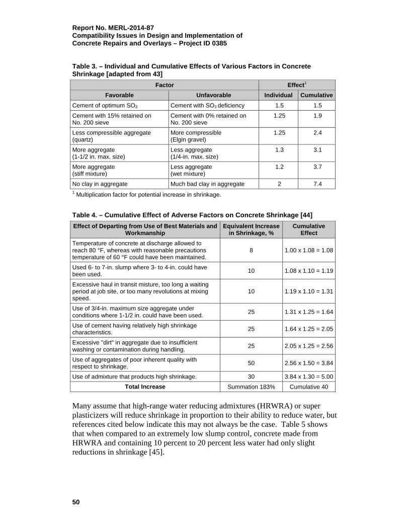
Report No. MERL-2014-87 Compatibility Issues in Design and Implementation of Concrete Repairs and Overlays – Project ID 0385 Table 3. – Individual and Cumulative Effects of Various Factors in Concrete Shrinkage [adapted from 43]
Factor Effect1
Favorable Unfavorable Individual Cumulative Cement of optimum SO3 Cement with SO3 deficiency 1.5 1.5
Cement with 15% retained on No. 200 sieve
Cement with 0% retained on No. 200 sieve
1.25 1.9
Less compressible aggregate (quartz)
More compressible (Elgin gravel)
1.25 2.4
More aggregate (1-1/2 in. max. size)
Less aggregate (1/4-in. max. size)
1.3 3.1
More aggregate (stiff mixture)
Less aggregate (wet mixture)
1.2
3.7
No clay in aggregate Much bad clay in aggregate 2 7.4 1 Multiplication factor for potential increase in shrinkage.
Table 4. – Cumulative Effect of Adverse Factors on Concrete Shrinkage [44] Effect of Departing from Use of Best Materials and
Workmanship Equivalent Increase
in Shrinkage, % Cumulative
Effect Temperature of concrete at discharge allowed to reach 80 °F, whereas with reasonable precautions temperature of 60 °F could have been maintained.
8 1.00 x 1.08 = 1.08
Used 6- to 7-in. slump where 3- to 4-in. could have been used. 10 1.08 x 1.10 = 1.19
Excessive haul in transit misture, too long a waiting period at job site, or too many revolutions at mixing speed.
10 1.19 x 1.10 = 1.31
Use of 3/4-in. maximum size aggregate under conditions where 1-1/2 in. could have been used. 25 1.31 x 1.25 = 1.64
Use of cement having relatively high shrinkage characteristics. 25 1.64 x 1.25 = 2.05
Excessive "dirt" in aggregate due to insufficient washing or contamination during handling. 25 2.05 x 1.25 = 2.56
Use of aggregates of poor inherent quality with respect to shrinkage. 50 2.56 x 1.50 = 3.84
Use of admixture that products high shrinkage. 30 3.84 x 1.30 = 5.00
Total Increase Summation 183% Cumulative 40
Many assume that high-range water reducing admixtures (HRWRA) or super plasticizers will reduce shrinkage in proportion to their ability to reduce water, but references cited below indicate this may not always be the case. Table 5 shows that when compared to an extremely low slump control, concrete made from HRWRA and containing 10 percent to 20 percent less water had only slight reductions in shrinkage [45].
50

Report No. MERL-2014-87 Compatibility Issues in Design and Implementation of
Concrete Repairs and Overlays – Project ID 0385
Table 5. – Effect of High-Range Water Reducers on Drying Shrinkage [45]
Cement
Normal Cement Content (lb/cu
yd)
Admixture Water
Content (lb/cu
yd)
Net Air (%)
Slump (in.)
Water Reduction
(%) 7 d 28 d 3 mo 6 mo 9 mo
21734 Type I 376
None 264 2 2.2 0.02 0.04 0.06 0.06 0.06
Mighty 150 230 2.2 2.1 12.7 0.03 0.04 0.05 0.05 0.05
Melment 239 1.7 1.7 9.6 0.02 0.04 0.05 0.05 0.05
Lomar-D 238 2.9 2 10 0.02 0.04 0.06 0.06 0.05
FX-032C 219 4.6 2.1 16.9 0.02 0.05 0.05 0.05 0.06
21734 Type I 517
None 258 2 2.8 0.03 0.04 0.06 0.06 0.06
Mighty 150 220 2.7 2.7 14.7 0.03 0.04 0.06 0.06 0.05
Melment 222 1.8 2.5 13.7 0.02 0.04 0.04 0.05 0.05
Lomar-D 217 2 2.4 15.9 0.03 0.04 0.05 0.06 0.05
FX-032C 206 4.7 2.7 20.1 0.02 0.04 0.05 0.05 0.06
21734 Type I 658
None 268 1.6 2.8 0.03 0.04 0.06 0.06 0.06
Mighty 150 215 2.2 3 19.7 0.03 0.04 0.05 0.06 0.05
Melment 220 1.8 2.2 18 0.02 0.04 0.04 0.05 0.05
Lomar-D 217 2 3 18.8 0.02 0.04 0.05 0.05 0.05
FX-032C 217 2.9 2.4 19.1 0.02 0.04 0.05 0.05 0.06
21736 Type I 658
None 287 2.1 3.2 0.03 0.05 0.06 0.07 0.07
Mighty 150 237 2.5 2.7 17.3 0.03 0.05 0.06 0.06 0.06
Melment 243 2.2 1.7 15.3 0.02 0.04 0.05 0.05 0.06
Lomar-D 232 2.3 2.6 18.9 0.02 0.04 0.05 0.06 0.06
4. Modulus of Elasticity
a. General The modulus of elasticity is a measure of the stiffness of a material. It is the ratio of stress to strain for tension or compression below the elastic limit of the material. Elastic refers to the reversible character of the dimensional change (as a spring would recover if compressed or stretched). A material with a higher modulus of elasticity is more rigid than a lower modulus material, which is more flexible. One way of visualizing this is to determine the slope of the straight line portion of a graph of stress (force per unit area; that is, lb/in2, MPa) versus strain (deformation per unit length; that is, inch per inch, mm/m). For repairs in concrete, the modulus of elasticity describes the accommodation of stress in a repair to transfer of load, and, to a certain degree, the tolerance of a material to volume changes due to shrinkage or thermal movement. The modulus of elasticity of cement-based repair materials is a very important property. Concrete repairs may be broadly classified as structural (load-carrying) or protective. Structural forces must be considered for structural repairs where
51

Report No. MERL-2014-87 Compatibility Issues in Design and Implementation of Concrete Repairs and Overlays – Project ID 0385 replacement of deteriorated but load-carrying concrete is required. In this case, the repair material may be subjected to tension, compression, or shear forces. Thus, a completely different approach is required when selecting repair materials for structural repairs than is required for protective repairs. It should be noted, however, that structural repair must also protect the underlying concrete and reinforcing steel from deterioration and corrosion [34]. Table 6 gives the elastic moduli of a number of common materials. As shown below, the range of stiffness varies by about 1 to 170,000. Table 6. – Approximate Elastic Moduli of Various Solids [46]
Material p.s.i. Rubber 1,000 Shell membrane of egg 1,100
Human cartilage 3,500
Human tendon 80,000
Unreinforced plastics, polythene, nylon 20,000
Plywood 1,000,000
Wood (along grain) 2,000,000
Bone 3,000,000
Concrete 3,600,000
Ordinary glasses 10,000,000
Aluminum alloys 10,000,000
Brasses and bronzes 17,000,000
Iron and steel 30,000,000
Aluminum oxide (sapphire) 60,000,000
Diamond 170,000,000
b. Influencing Factors The modulus of elasticity of repair materials is important in determining the stress in composite repair systems at interfaces between the repair and existing concrete substrate. The factors that affect the modulus of elasticity of cement-based materials are related to compressive strength and density. Factors that affect strength are cement content, water to cementitious materials ratio, aggregate type, size and grading, curing conditions, and age at the time of testing. Thus, these factors also influence modulus. However, one apparent inconsistency in the compressive strength-elastic modulus relationship is the moisture dependency. The strength of saturated concrete or other cement-based materials is lower than that of dry materials, while for elastic modulus, the reverse is true. For a given cement-based material, the modulus of elasticity increases with age during hardening in accordance with the relationship that is approximately proportional to the square root of the compressive strength, and it is greatly
52

Report No. MERL-2014-87 Compatibility Issues in Design and Implementation of
Concrete Repairs and Overlays – Project ID 0385
influenced by the humidity of the air in which the specimens were stored [6]. For example, for concrete containing 520 pounds per cubic yard (lb/yd3) (350 kilograms per cubic meter [kg/m3]) of cement with siliceous aggregates, test results have shown various moduli at 200 days (table 7) [47]. Table 7. – Moduli of Elasticity of Concrete Cured at Different Relative Humidities [47]
Moduli of Elasticity of Concrete Cured at Different Relative Humidities
Relative Humidity of Curing Medium %
Modulus of Elasticity lb/in2 (kg/cm2)*
35 4.8x10⁶ (340,000)
50 5.2x10⁶ (365,000)
75 5.5 x10⁶ (385,000)
99 6.4x10⁶ (450,000)
Water 6.4x10⁶ (450,000)
*kilogram per square centimeter
The modulus of elasticity of materials is substantially affected by the type and amount of aggregate. Figure 16 [37], and figure 17 [48] demonstrate the effect of aggregate on the modulus of elasticity of concrete. Figure 18 shows how the various constituents impact the stress versus strain for concrete.
Figure 16. – Effect of aggregate on the modulus of elasticity of concrete [37].
53

Report No. MERL-2014-87 Compatibility Issues in Design and Implementation of Concrete Repairs and Overlays – Project ID 0385
Figure 17. – Effect of w/c ratio and type of aggregate upon modulus of elasticity. Mixtures contained six sacks of cement per cubic yard (age of test of 56 days) [48].
Figure 18. – Stress strain relationships from cement paste, aggregate, and concrete [6]. Because the value of elastic modulus is partly dependent on microcracking at the matrix-aggregate interface, caused by elastic mismatch between the aggregate and the cement matrix, the shape, texture, and total amount of aggregate will influence the elastic modulus.
54

Report No. MERL-2014-87 Compatibility Issues in Design and Implementation of
Concrete Repairs and Overlays – Project ID 0385
An increase in modulus can also be expected from a decrease in the w/c. Figure 17 [48] shows the relationship between w/c and modulus for several aggregate types. Cracks and flaws exist in a composite repair system for reasons other than service loads; for example, shrinkage of the repair material, the difference in the coefficient of thermal expansion (CTE) of the repair material versus the substrate material, or the difference in the modulus of elasticity of the repair material versus the substrate concrete. Therefore, in some cases, the compatibility in modulus of elasticity becomes an important factor because incompatibility may lead to considerable stress concentration when widely differential volume changes of the repair material occur in relation to the concrete substrate. In such situations, the interfacial bond region (transition zone) is the weak link in the repair system, so cracks will tend to form in this region. In certain cases where bond strength is high, cracks will occur in the matrix of the material having the higher modulus of elasticity. When external load is perpendicular to the bond line (as in the case of repaired pavement), differences in modulus of elasticity between the repair material and concrete substrate are not normally problematic. In vertical repairs, however, where the service load is parallel to the bond line, differences in modulus of elasticity may cause load transfer to the high modulus material if the other materials yield under the stress. If the load transfer is beyond the load-bearing capacity of the higher modulus material, it will fracture and damage the structure. Figure 19 summarizes factors that affect the modulus of elasticity of concrete (and other cement-based materials).
Figure 19. – Various parameters that influence the modulus of elasticity of concrete [34].
55

Report No. MERL-2014-87 Compatibility Issues in Design and Implementation of Concrete Repairs and Overlays – Project ID 0385 5. Creep
The deformation of a material in response to load is known as rheological behavior [49]. While instantaneous effects and time-dependent effects are not entirely separable, it is common to consider them separately as elastic properties (instantaneous) and creep (time-dependent). When concrete is loaded, the deformation caused by the load may be divided into two parts: (1) a deformation, which occurs immediately; and (2) a time-dependent deformation, which begins immediately but can continue for years. The latter deformation is called “creep.” A material that is loaded, deflects, and then returns to its original dimensions after release of the load is elastic. Creep is a slow plastic deformation and is defined in ACI CT-13 [39] as “time-dependent deformation due to sustained load.” Creep is considered an isolated rheological phenomenon associated with the gel structure of cement paste. When a cement-based material is loaded and remains under the influence of this load over a long period of time, it continues to deform for a long period of time. It is commonly stated in literature that creep and shrinkage are interrelated phenomena because there are a number of similarities between the two. Table 8 lists the various parameters that can be expected to affect creep and shrinkage [50]. Table 8. – Parameters Affecting Shrinkage and Creep of Concrete [50]
Like shrinkage, creep is a cement-paste property with aggregate that acts as a restraint. The first known study of creep was published by Woolson [51]. Troxell
Paste parameters Porosity: w/c ratio and degree of hydration Age of paste: w/c ratio and degree of hydration Curing Temperature Cement composition Moisture content
Admixture Concrete parameters Aggregate stiffness Aggregate content (cement content) Volume-to-surface ratio Thickness Environmental parameters Applied stress: affects only creep Duration of load: affects only creep Relative humidity Rate of drying Time of drying
56

Report No. MERL-2014-87 Compatibility Issues in Design and Implementation of
Concrete Repairs and Overlays – Project ID 0385
et al. [52] were the first researchers to bring out the important influence of the humidity of the curing medium on creep. Numerous theories have been advanced to explain creep. A principal view among investigators [53, 54] is that creep is closely related to shrinkage. In creep, gel water movement is caused by changes in applied pressure instead of differential hygrometric conditions between the concrete and its environment. This concept is supported by the similar manner in which creep and shrinkage curves are affected by such factors as w/c, mixture portions, properties of aggregate, compaction, curing conditions, and degree of hydration. Another explanation of the effect of gel water [55, 56] is delayed elasticity. If a load is suddenly imposed on a body consisting of a solid elastic skeleton with its void filled with viscous fluid, the load will be carried initially by the fluid and will gradually be transferred to the skeleton as the fluid flows away under load. This is the behavior exhibited by the rheological model known as a Kelvin body, which consists of a spring and dashpot in parallel. The concept of delayed elasticity has been chiefly responsible for the widespread attempts to reproduce the rheological behavior of concrete by means of rheological models. Figure 20 shows a typical creep curve. Within the normal stress ranges, creep is proportional to stress. The ultimate magnitude of creep of plain concrete per unit stress can range from 0.2 to 2 millionths in terms of length but is ordinarily about 1 millionth or less. In the survey made by Smadi [57], the load-induced, time-dependent deformations of concrete are largely attributed to the movement of capillary and absorbed water within the concrete system, to the movement of water in the environment, and to the development and propagation of internal microcracks. The rate and magnitude of creep strain associated with the first two processes would depend on the relative volume of pores and spaces in the cement gel and on the amount of water occupying these pores at the time of loading. When the shrinkage strain in an elastic material is fully restrained, it results in elastic tensile stress. The material is expected to crack when a combination of the elastic modulus and the shrinkage strain induces a stress level that reaches its tensile strength (figure 21, curve (a)). Given the low tensile strength of cement-based materials, this does happen in practice but, fortunately, not exactly as predicted by the theoretically computed values because cement-based materials are not truly elastic materials. These materials show elastic, as well as inelastic, behavior on loading and shrinkage on curing. Thus, cement-based materials are, in fact, viscoelastic materials. To understand why a concrete repair may not crack at all, or may crack but not soon after exposure to the environment, consider how a repair would respond to sustained stress or to sustained strain. As explained above, the gradual increase in strain with time under a given level of sustained stress is called creep. Conversely,
57
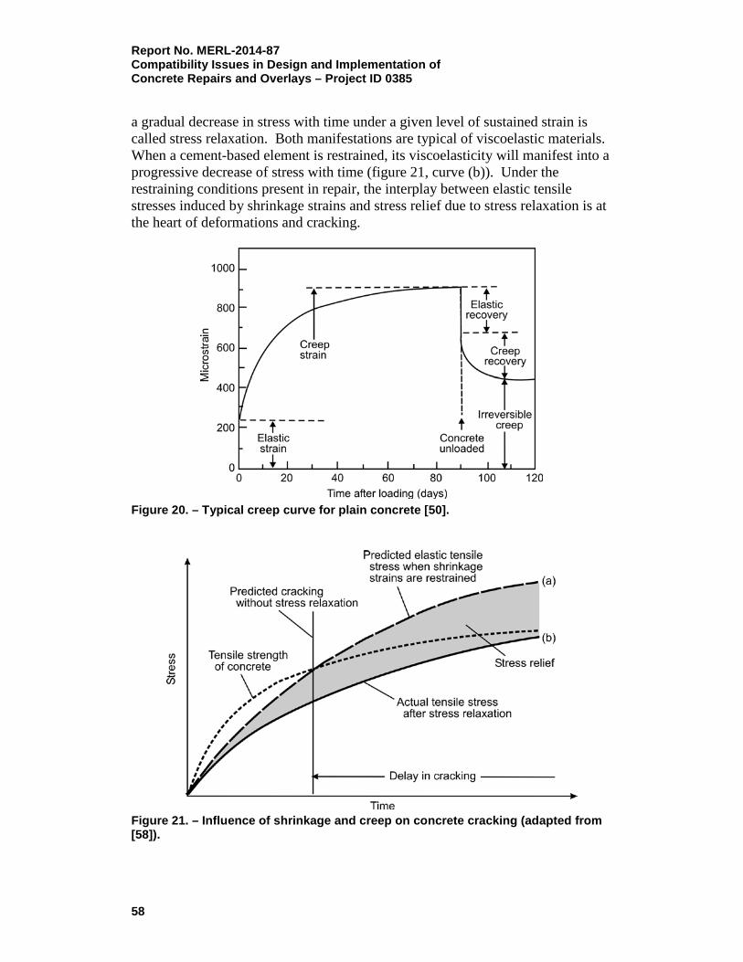
Report No. MERL-2014-87 Compatibility Issues in Design and Implementation of Concrete Repairs and Overlays – Project ID 0385 a gradual decrease in stress with time under a given level of sustained strain is called stress relaxation. Both manifestations are typical of viscoelastic materials. When a cement-based element is restrained, its viscoelasticity will manifest into a progressive decrease of stress with time (figure 21, curve (b)). Under the restraining conditions present in repair, the interplay between elastic tensile stresses induced by shrinkage strains and stress relief due to stress relaxation is at the heart of deformations and cracking.
Figure 20. – Typical creep curve for plain concrete [50].
Figure 21. – Influence of shrinkage and creep on concrete cracking (adapted from [58]).
58

Report No. MERL-2014-87 Compatibility Issues in Design and Implementation of
Concrete Repairs and Overlays – Project ID 0385
The deformability of cement-based materials in tension has never received much attention. Likewise, little consideration has been given to tensile creep in the design of new concrete structures, probably because the tensile properties of concrete are generally disregarded, as well as the difficulties related to the accurate measurement of these properties. Vaysburd et al. explained that it is not appropriate to use compressive properties of cement-based materials (such as elastic modulus and creep) instead of tensile properties, simply because they are easier to evaluate, because they produce significant errors in evaluating the crack-resistance of repair materials [59]. The capacity of the material to deform in tension, especially its creep potential, could help prevent shrinkage-induced cracking and, thus, improve the durability of concrete repairs. Bissonnette et al. offered a substantial contribution to understanding the criticality of the tensile creep property of cement-based materials in concrete repair [60, 61]. The authors of these papers concluded that shrinkage is one of the major problems affecting the durability of thin concrete repairs. Tensile creep properties can have a large impact on induced tensile stresses in the repair layer. These stresses can eventually exceed the tensile strength of the material and cause cracking and debonding. When considering the strain balance in a concrete element in which shrinkage is partially or fully restrained, the components that can counteract the shrinkage strain (before cracking occurs) are the elastic strain and the creep strain. Because the elastic strain capacity in tension is very small (~100 to 200 micrometers per meter [µm/m]), only the tensile creep component can play an important role in reducing the restrained shrinkage stresses. The ability to select the concrete mixtures that are best suited for thin repairs, and, more precisely, those that have a higher creep to shrinkage ratio, will improve the resistance of thin concrete repairs to cracking. It is the tensile properties of cement-based materials that greatly influence the cracking mechanism, the bond and shear behavior, and the failure criteria under combined stresses typical for repair. A critical factor in determining tensile strain capacity is tensile creep. Measuring tensile creep and modulus are more difficult than in compression, primarily because of the relatively low tensile strength of the material. With lower strength and lower stress levels that can be applied, creep strains for tension are small and hard to measure. Because of this, compressive creep, if available, is being used to analyze the tensile behavior of cement-based materials. When not available, compressive creep is estimated based on the data for concrete in compression. Both techniques have been found to produce significant errors in estimating the amount of tensile creep that a cement-based material experiences upon curing. The fracture behavior of cement-based material in tension is markedly different from its compressive behavior. Cracking in a tensile stress field is unstable, and
59
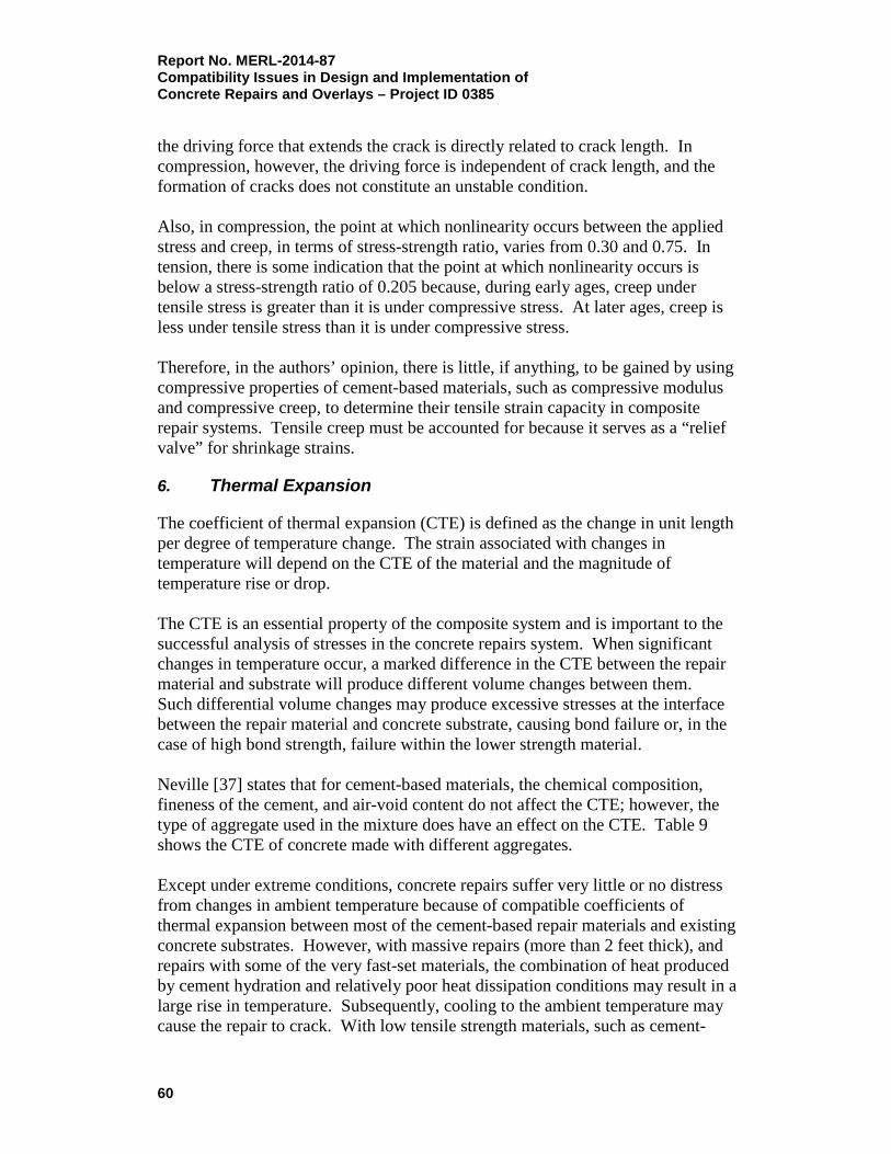
Report No. MERL-2014-87 Compatibility Issues in Design and Implementation of Concrete Repairs and Overlays – Project ID 0385 the driving force that extends the crack is directly related to crack length. In compression, however, the driving force is independent of crack length, and the formation of cracks does not constitute an unstable condition. Also, in compression, the point at which nonlinearity occurs between the applied stress and creep, in terms of stress-strength ratio, varies from 0.30 and 0.75. In tension, there is some indication that the point at which nonlinearity occurs is below a stress-strength ratio of 0.205 because, during early ages, creep under tensile stress is greater than it is under compressive stress. At later ages, creep is less under tensile stress than it is under compressive stress. Therefore, in the authors’ opinion, there is little, if anything, to be gained by using compressive properties of cement-based materials, such as compressive modulus and compressive creep, to determine their tensile strain capacity in composite repair systems. Tensile creep must be accounted for because it serves as a “relief valve” for shrinkage strains.
6. Thermal Expansion
The coefficient of thermal expansion (CTE) is defined as the change in unit length per degree of temperature change. The strain associated with changes in temperature will depend on the CTE of the material and the magnitude of temperature rise or drop. The CTE is an essential property of the composite system and is important to the successful analysis of stresses in the concrete repairs system. When significant changes in temperature occur, a marked difference in the CTE between the repair material and substrate will produce different volume changes between them. Such differential volume changes may produce excessive stresses at the interface between the repair material and concrete substrate, causing bond failure or, in the case of high bond strength, failure within the lower strength material. Neville [37] states that for cement-based materials, the chemical composition, fineness of the cement, and air-void content do not affect the CTE; however, the type of aggregate used in the mixture does have an effect on the CTE. Table 9 shows the CTE of concrete made with different aggregates. Except under extreme conditions, concrete repairs suffer very little or no distress from changes in ambient temperature because of compatible coefficients of thermal expansion between most of the cement-based repair materials and existing concrete substrates. However, with massive repairs (more than 2 feet thick), and repairs with some of the very fast-set materials, the combination of heat produced by cement hydration and relatively poor heat dissipation conditions may result in a large rise in temperature. Subsequently, cooling to the ambient temperature may cause the repair to crack. With low tensile strength materials, such as cement-
60

Report No. MERL-2014-87 Compatibility Issues in Design and Implementation of
Concrete Repairs and Overlays – Project ID 0385
based repair materials, it is the contraction strain from cooling that is more important than the expansion from heat generated by temperature rise. Table 9. – Coefficient of Thermal Expansion of 1:6 Concretes Made with Different Aggregates [adapted from 37]
Type of Aggregate Air-cured Concrete 10-6 per °F
Water-cured Concrete 10-6 per °F
Air-cured and Wetted Concrete 10-6 per °F
Gravel 7.3 6.8 6.5
Granite 5.3 4.8 4.3
Quartzite 7.1 6.8 6.5
Dolerite 5.3 4.7 4.4
Sandstone 6.5 5.6 4.8
Limestone 4.1 3.4 3.3
Portland Stone 4.1 3.4 3.6
Blast Furnace Slag 5.9 5.1 4.9
Foamed Slag 6.7 5.1 4.7
°F – degrees Fahrenheit
Table 10 [13] shows typical properties of repair materials. Table 10. – Typical Short-Term Properties of Repair Materials [13]
Property Resin Mortar
Polymer Modified Cementitious Mortar
Plain Cementitious Mortar
Compressive strength (N/mm2) 50 – 100 30 – 60 20 – 50
Tensile strength (N/mm2) 10 – 15 5 – 10 2 – 5
Modulus of elasticity in compression (kN/mm2) 10 – 20 15 – 25 20 – 30
Coefficient of thermal expansion (per °C) 25 – 30 x 10-6 10 – 20 x 10-6 10 x 10-6
Water absorption (% by weight) 1 – 2 0.1 – 0.5 5 – 15
Maximum service temperature (°C) 40 – 80 100 – 300 > 300
kN/mm2 – kiloNewtons per square millimeter °C – degree Celsius Numerous examples in the literature demonstrate that thermal compatibility is a critical property to consider when specifying and selecting repair materials, regardless of their chemical composition. Polymer resins exhibit CTE up to several times greater than concrete. This gap in thermal compatibility can be reduced by the addition of aggregates in the polymer mortar. Such mortars, when passing the ASTM C884 test (thermal compatibility between concrete and epoxy),
61

Report No. MERL-2014-87 Compatibility Issues in Design and Implementation of Concrete Repairs and Overlays – Project ID 0385 have the best potential for successfully repairing structures that experience relatively large daily and seasonal temperature changes. Bridge and parking deck slabs employ horizontal repair techniques in which the forces of gravity allow the use of low viscosity epoxy mortars with high aggregate content. With point-to-point aggregate contact in the resin, achieving thermal compatibility is more likely, and this is the type of application where epoxy mortar may be specified. For repairs involving overhead and vertical applications without formwork, gravity forces work against achieving point-to-point aggregate contact, and thus thermal compatibility. In these cases, only thixotropic (nonsag or gel) polymer resins with limited aggregate content can be used. However, because of the low aggregate content, they are thermally incompatible with concrete and should not be specified for repairs of structure with relatively high temperature changes [6]. Sprinkel [62] reported that the temperature changes to which bridge decks are typically subjected can be sufficient to cause deterioration and eventual failure of polymer concrete overlays. Deterioration is caused by the development of stresses in the bond between the concrete and the overlay. The stresses are the result of differences in the moduli of elasticity and the CTEs in the two materials. Thermally induced cracks have been noted in the overlay, the base concrete, and the bond interface (the majority cannot withstand stress). Cracks in the overlay increase its permeability, and cracks in the base concrete or the bond interface lead to delamination of the overlays. According to Sprinkel [62], overlay failures can be grouped into three basic types, as follows:
1. The formation of vertical cracks through the thickness of the overlay. The formation of vertical cracks increases the permeability of the overlay and reduces its effectiveness in preventing the infiltration of chlorides. It will be the predominant mode of failure on bridges where the shear strength of the base concrete and the bond strength are high or the modules of elasticity of the overlay is high, or the tensile strength is low. Failure will likely occur after a few cycles of temperature change. The overlay will likely remain bonded to the base concrete until the freezing and thawing action causes delamination;
2. The shearing of portland cement concrete below the bond line. Shearing of the concrete below the bond line causes the overlay to delaminate with concrete remaining bonded to its underside. Failure is most likely to occur when the shear strength of the base concrete is low, the bond is good, and the tensile strength of the overlay is high. Failure will likely occur after a few cycles of temperature change and will result in the delamination of the polymer-concrete overlay;
3. The delamination of the bond between the polymer-concrete (PC) overlay and the base concrete. Delamination of the bond between the PC overlay and the base concrete causes the overlay to delaminate with no concrete
62

Report No. MERL-2014-87 Compatibility Issues in Design and Implementation of
Concrete Repairs and Overlays – Project ID 0385
remaining on the underside. Failure is likely to occur when either the surface preparation prior to the installation of the overlay is poor or when the shear strength of the base concrete and the tensile strength of the overlay are high. Where the initial bond is good, a significant number of thermal cycles may be required to complete the failure.
C. Permeability Compatibility
Permeability of repair materials is one of the primary properties of importance in achieving compatibility and durability in repair projects. If the use of low permeability concrete in new construction is the key to achieving durability, this rule does not necessarily apply to concrete repairs, where the situation is more complex. Unfortunately, when it comes to repairs, there is no “rule of thumb.” Each situation is different and needs to be accurately analyzed.
1. Permeability in Repair
Hanley et al. [63] presented detailed analysis of the issue from the point of view of effects of permeability on corrosion activities in concrete repair. The authors address two cases: (1) compatible permeability with the substrate repair material, and (2) incompatible low permeability repair material. They state that an approach that has sometimes been endorsed in practice is to reduce the potential difference between the patch and the substrate by using a patching material that has permeability similar to the substrate. It is typically the cathodic reaction that controls corrosion. The anodic site can change because of the removal of damaged steel and the passivation of the steel in the patch by the high pH of the patching material. Therefore, it is the change in the anodic reaction in the patch that causes the difference in potential. The permeability of the patching material does not affect the anodic reaction; rather, by controlling the diffusion of oxygen and transport of hydroxyl ions within the patch, the cathodic reaction is affected. By selecting a repair material with similar permeability to the substrate, it can be assumed that the cathodic reactions in both the patch and the substrate will be similar. Because the cathodic reaction will likely remain the same, this approach will, in most cases, not be effective. The traditional view described above deals mostly with corrosion potentials or, in other words, the thermodynamics of the microcell corrosion process. The different view described in the following text addresses corrosion potentials as well, but it also focuses on the kinetics of the microcell corrosion process. In the most basic terms, thermodynamic science deals with predicting whether reactions or processes will occur, while kinetic science centers on the rate at which certain reactions will occur. Similarly, in concrete, reinforcing steel potentials indicate whether corrosion is likely to occur, but they do not control reaction rates. As stated previously, it is the kinetics of the cathodic reaction that controls the
63

Report No. MERL-2014-87 Compatibility Issues in Design and Implementation of Concrete Repairs and Overlays – Project ID 0385 corrosion rates of reinforcing steel in concrete. Therefore, it seems prudent to incorporate kinetic theory in the analysis of corrosion of reinforcing steel in repaired concrete structures. Microcell corrosion involves four basic entities: (1) an anode, (2) a cathode, (3) an electrical connection, and (4) an electrolytic solution. When the reaction reaches a steady state, a circuit is set up that involves the flow of hydroxyl ions through the concrete electrolyte. In order for the cathodic reaction to take place, oxygen must be present; thus, diffusion of oxygen through the concrete must take place to supply the cathodic reaction. Figure 22 shows the microcell for a repair; however, in this case, the patching material is much less permeable than the substrate. If a patching material is used that reduces the flow of oxygen to the reinforcing steel, the cathodic reaction will be slower than it would be for an identical corrosion cell with a more permeable material surrounding the cathodic site.
Figure 22. – Repaired anode microcell (less permeable patch) [63]. In addition to limiting the availability of oxygen within the patch, a low-permeability patching material will inhibit the transport of hydroxyl ions from the patch, thus limiting its contribution to the anodic reaction sites outside of the path. The less permeable the patching material is, the lower the simulated current flows will be to the anodic substrate. It seems logical, therefore, to conclude that using a patching material with a higher electrolytic resistance (i.e., a less permeable material) should reduce the cathodic contribution of a patch to surrounding substrate.
64
Report No. MERL-2014-87 Compatibility Issues in Design and Implementation of
Concrete Repairs and Overlays – Project ID 0385
The authors of the paper concluded that although a tremendous amount of information exists in the literature on corrosion of steel in concrete, comparatively very little work has been done that specifically addresses the mechanisms of corrosion involved with repair of concrete structures. Theoretical analysis of corrosion processes involved in repaired concrete structures has traditionally focused on potential differences between the patched areas and the surrounding substrate. This analysis has led to repair practices that suggest using repair materials that have the same permeability as the substrate concrete. A different analysis, including both potential theory as well as kinetic theory, suggests that repair materials that are less permeable should have less impact on the surrounding substrate, as well as provide a higher level of protection in the patched area. Unfortunately, sufficient experimental data supporting either approach is still needed. Emmons and Vaysburd [7] commented that using low permeability repair materials, regardless of repair specifics, can lead to unsuitable choices, compatibility problems, and eventual repair failures. Durability of the repair can be negatively affected in many situations when repair and substrate have different, incompatible permeability levels. An example of unsuccessful use of a low-permeability repair material [64] is discussed below. Latex- modified shotcrete was used around a pier cap to repair damage from deicing salts; however, the top of the cap was not protected, and the source of the salt and moisture penetration was not eliminated. In this case, a more severe attack on the reinforcement developed, with subsequent steel corrosion and spalling. Water with deicing salts on the bridge deck collected on the pier cap, penetrated it, and then was unable to escape. Without such a repair, continued deterioration could have been expected; however, with the repair, it was accelerated and intensified. The lesson derived from this example is that in a number of cases, the selection of low-permeability repair materials not compatible with existing concrete may lead to failure. It is important to note that a few “through” cracks in the repair, or its deboning, will drastically offset the benefit of having a very low permeability repair material. Microcracks connected with wider cracks originating from the repair surface play a much greater role in reducing the permeability and durability than the permeability of repair material itself. Other effects of incompatible low permeability involve trapping moisture behind the repair material, which can accelerate several deterioration mechanisms. Vaysburd and Emmons [7] describe encapsulation of concrete. Throughout North America, thousands of bridge columns have been repaired and/or protected with vapor barrier producing systems that result in encapsulation of concrete. As the temperature drops, moisture in vapor form migrates towards the barrier and converts into liquid form at the dew point. Water solubles in the concrete are
65

Report No. MERL-2014-87 Compatibility Issues in Design and Implementation of Concrete Repairs and Overlays – Project ID 0385 carried along in this migration process. Liquid will then convert into ice at freezing temperatures, resulting in freeze-thaw damage at the edge of the vapor barrier. When this action is reversed by an upswing in temperatures, moisture reconverts back to vapor, leaving water solubles behind in a crystalline form because vapor is not capable of making a solution. Repeated cycles can eventually lead to severe deterioration from either one, or a combination, of these damaging forces. These examples show that using low permeability repair materials, regardless of the situation, does not always work. It is completely conceivable that, for the cases discussed above, repairs materials that had compatible permeability with the existing concrete should have been specified. It is correct that permeability is the key to durability of concrete. However, a repaired structure is not a composite material; it is a composite system of materials. This concept has not been effectively considered. It appears advisable that the single concept of using low-permeability repair materials be abandoned due to the large amount of conflicting evidence regarding its success. In 2006, Vaysburd [8] concluded that appropriate permeability of repair materials is one of the primary properties of importance. Further, more work is necessary to define what degree of permeability should be recommended for repair materials for different repair situations. Most likely, there is now a single question: Is a very low permeability or matching (with the existing concrete) permeability more effective? The choice depends, many times, on the particular transport mechanisms in the repair system. Transport of substance through and in the repair system is a very complex process that consists of a combination of liquid flow through macrocrack and microcrack systems, capillary transport, diffusion, and osmotic effects. The exact contribution of each process needs to be quantified in each particular repair situation. The effects of such variables as location of the repair in the structure, the internal environment in the repair system, the amount and distribution of cracks in both phases of the composite repair system, the temperature, moisture, and stresses need to be considered.
2. Stress Effect on Permeability
The type and level of stress in the material can affect its permeability and the rate of its interaction with the environment. Compression or tension of the materials can induce reversible changes in the size of pores. Strain can affect not only the macrostructure, but also the microstructure, of materials. Defects in the hardened cement matrix and tips of microcrack can get overstressed, causing microcracks to propagate and, in some cases, join, thereby increasing the permeability of
66

Report No. MERL-2014-87 Compatibility Issues in Design and Implementation of
Concrete Repairs and Overlays – Project ID 0385
material. Tension in all cases increases the permeability of the repair and reduces its protective capabilities. The state of stress influences the resistance of the repaired structure to attack by various aggressive environments. An industrial environment may present different combinations of loading and physical and chemical attacks. The loading (direction and level of stress, duration of load) and the environmental influence (type and concentration of the active substance, ambient temperature, and duration of attack) are of prime importance for the resistance of a repaired concrete structure. As discussed earlier in this report in section II, in much of the research conducted in the area of durability of concrete repairs, the various “stress” factors are most often addressed individually. For instance, in evaluating the freeze-thaw resistance of concrete, the specimens are subjected to a fixed temperature cycle in an unloaded state. In reality, however, the system is exposed to many factors, including the combined effects of freezing and thawing, wetting and drying, dynamic loading, and corrosion of reinforcing steel. Models for such environmental fatigue, or real-world processes, need to be developed.
3. Permeability and Cracking
Even when incompatible permeabilities between repair material and substrate are justified, it must be acknowledged that a few “through” cracks in the repair will drastically offset the benefit of a low permeability repair material. Microcracks in the substrate and repair, in combination with wider cracks in both repair phases, will play a much greater role in reducing durability than the permeability of the repair itself. Cracking is one of the most critical factors in the overall permeability and durability of repaired structures. Figure 23 summarizes the causes of cracking in a concrete repair system [59]. The authors analyzed the effect of cracking on permeability of reinforced concrete and determined that after the pores and microcracks form a continuous network, the penetration of oxygen to steel becomes easy, and corrosion will accelerate. For significant corrosion to occur, it is not just the crack width, but the total area covered by cracks, especially next to the surface of reinforcing steel, that is important. In a marine environment, especially in a tidal zone, numerous physical and chemical processes are at work, which tend to enlarge both the size and area of microcracks and pores. This, in turn, leads to an increase in permeability of the concrete, which sets the stage for corrosion of the embedded steel. It is likely that significant corrosion of steel can occur only when the permeability of concrete becomes high enough to permit access of oxygen to large areas of reinforcement. Substantial steel corrosion leads to further microcracking in concrete and eventual enlargement of microcracks into large cracks, which causes the permeability of
67

Report No. MERL-2014-87 Compatibility Issues in Design and Implementation of Concrete Repairs and Overlays – Project ID 0385 the concrete to increase even more. It is at this stage that the corrosion and cracking phenomena begins to interact. Here, it becomes difficult to separate the cause from the effect. The effect appears to reproduce the cause.
Figure 23. – Causes of cracking in concrete repair system [59]. In 1982, Mehta and Gerwick [65] proposed a model on cracking-corrosion interaction (figure 24).
68

Report No. MERL-2014-87 Compatibility Issues in Design and Implementation of
Concrete Repairs and Overlays – Project ID 0385
Figure 24. – Schematic model of cracking-corrosion interaction (adapted from [65]).
4. Micropermeability and Macropermeability
Cracking is probably the biggest single factor in the overall permeability and durability of a structure when it is exposed to a harsh environment. From a durability standpoint, an ideal concrete would have no cracks at all. In practice, one should minimize the width and depth of the cracks. Detwiler [66] introduced the “micro” and “macro” aspects of concrete permeability, stating that although the specific values of permeability and diffusivity for a given concrete vary, depending on the substance that is moving through it, the principles for obtaining low values are the same. It is convenient to divide the concept of permeability into macropermeability and micropermeability. Macropermeability is largely in the hands of structural engineers, who may not even be aware of how their designs and specifications effect the durability. Only when proper attention has been paid to the “macro” aspects of permeability does it become worthwhile to examine the “micro” aspects. In addition to the many causes of cracking discussed previously, cold joints can act like cracks with regard to permeability and durability. About 35 years ago, Valenta observed that “continuous cracks linking into wider cracks originating
69

Report No. MERL-2014-87 Compatibility Issues in Design and Implementation of Concrete Repairs and Overlays – Project ID 0385 from the concrete surface play the biggest role in reducing permeability” [67]. The effect of cracking on permeability on concrete repair systems was addressed by Vaysburd and Emmons, who proposed a model of concrete repair failure caused by cracking (figure 25) [68] in their analysis on role of cracking.
Figure 25. – Model of concrete repair failure caused by cracking [68]. Acid gasses and aggressive ions penetrate cracked materials much easier than crack-free materials. The active coefficient of carbon dioxide diffusion (penetration) in a concrete crack 0.20 mm (0.008 inch) wide is approximately
70

Report No. MERL-2014-87 Compatibility Issues in Design and Implementation of
Concrete Repairs and Overlays – Project ID 0385
three orders of magnitude higher that it is in average quality, crack-free concrete [70]. The same is true for the transport of aggressive ions; the rate of substance transfer by capillary suction is even greater. According to data, reinforcement in a crack wider than 0.1 mm (0.004 inch) initially corrodes more rapidly than in unprotected steel, both in the air and with cyclic wetting and drying. Chlorides also penetrate more quickly through cracks towards the reinforcement. Cracks often have a high chloride concentration at the base of the crack near the reinforcing steel. In their analysis on the role of cracking on performance of concrete repair systems, Vaysburd and Emmons [69] concluded that “the width and direction of cracks are not of critical importance. The amount of cracks per unit of area is critical.” The permeability-cracking phenomena in concrete repair have been described by Vaysburd [71] and Vaysburd and Emmons [3]. It is also discussed hereafter. Specification of chloride permeability limits, based on the ASTM C1202 [72] test method, is a standard practice in North America. The standard specimen (formed in a laboratory or extracted in field) is certainly crack-free. Four hundred coulombs is “very good,” while four thousand coulombs is “very bad.” The specimen that was extracted and tested (shown in figure 26) had permeability below 400 coulombs. Of course, this result is very misleading and not representative of the repair material’s actual permeability.
Figure 26. – Low permeability material – high permeability repair. The core sample will have low permeability, but the crack allows for high permeability in the repair [71]. The material’s micropermeability (between the cracks) is important and has to be considered and limited, but only after the issues of macropermeability are successfully addressed by specifying an allowable shrinkage value. The transport of aggressive agents is controlled first by the macropermeability, and then by the micropermeability. The aggressive agents in the presence of cracks are taking the route of least resistance: the network of cracks and microcracks.
71
Report No. MERL-2014-87 Compatibility Issues in Design and Implementation of Concrete Repairs and Overlays – Project ID 0385 The primary significance of deformations caused by moisture-related effects in cementitious materials is whether or not their interaction would lead to cracking. Here, the magnitude of the restrained shrinkage strain is the most important factor to be specified. Linking the two aspects of permeability (macro and micro) is a measure of the cement-based materials protective quality. There can be little doubt that macropermeability is the most important factor.
5. Testing the Micropermeability
Presently, concrete and repair material permeability is being widely tested according to the ASTM C1202 [72], “Standard Test Method for Electrical Indication of Concrete’s Ability to Resist Chloride Ion Penetration,” but the reliability of the test is questionable. For example, is the electric charge passed through the cementitious materials of various chemical and mineralogical compositions directly related to the rate of chloride penetration [73]? Zhang and Gjørv [74] concluded that there is no direct correlation between chloride penetration and the charge passed by the test method. The reasons for the differences are discussed below. The electrical conductivity of concrete depends not only on its microstructure, but also on conductivity of the pore solution, including all the ions present, such as sodium, potassium, hydroxyl, and chloride ions. Consequently, a charge in electrical conductivity of a saturated concrete at constant temperature can be due to a variation in the composition of the pore solution or a change in the rate of ion diffusion [75]. The relationship between electrical conductivity and diffusion may vary with the mechanism of diffusion and the type of diffusion (volume diffusion, boundary diffusion, and surface diffusion) [76]. The measurement of electrical conductivity of concrete, according to the standard, is also based on the rate of ion penetration into the concrete before a stable flow has been reached, while the observed chloride penetration, based on concentration measurements in the sodium hydroxide cell, is based on the rate of chloride penetration through the concrete after a stable flow has been reached. Shi et al. [77] stated that the ASTM C1202 test is, in fact, a measurement of the electrical conductivity of concrete. This means that the ranking specified in ASTM C1202 depends mainly on the electrical conductivity of concrete. In one study, chloride ions only penetrated one-third or less of the specimen length during a rapid chloride permeability test of concrete with a passed charge of 3,200 coulombs. The transport of ions in concrete depends on the permeability and pore structure of the concrete, while the electrical conductivity depends on both the permeability and pore structure characteristics and the electrical conductivity of the pore solution, which is determined by the composition of the pore solution. The effect of pore solution composition on the electrical conductivity of a pore solution will be the same as the effect on the electrical
72

Report No. MERL-2014-87 Compatibility Issues in Design and Implementation of
Concrete Repairs and Overlays – Project ID 0385
conductivity of concrete if the modifications in pore structure, due to the replacement of portland cement with supplementary cementing materials, are not considered. The authors concluded that chemical composition of pore solution has little to do with transport of chloride ions in concrete; thus, it is incorrect to use passed charge to rank the chloride penetration resistance of concrete made with supplementary cementing materials.
D. Electrochemical Compatibility
1. General
The driving force for the phenomenon of corrosion in repair systems has been attributed to the electrochemical incompatibility between the repair and substrate. Electrochemical incompatibility is defined as the imbalance in electrochemical potential between different locations of the reinforcing steel because of their dissimilar environments caused by a repair [78]. The dissimilar environments can be due to the differences in physical properties, chemistry, and internal environments. To this end, Emmons and Vaysburd listed the difference between new construction and repair jobs as a guide for proper selection of repair strategies [79]. Figure 27 presents a holistic model of concrete repair failure. Vaysburd et al. [22] addressed the relationship between durability and service life of repaired structures, as well as electrochemical compatibility issues. To provide adequate resistance to aggressive actions, it is necessary to foresee the impacts of the repair on the overall damage mechanism necessitating the repair. This, in turn, helps show how such deterioration is prevented or, more realistically, how to ensure a sufficiently slow deterioration process. In other words, the aggressiveness of the existing internal (i.e., inside the structure) and external environments, their interaction, and the possible changes caused by the repair should be given full consideration at the design stage. All of these analyses are necessary to achieve electrochemical compatibility and fulfill the required durability and structural safety of aging infrastructure. The authors admit precise analysis of electrochemical compatibility is very difficult. The difficulties are mainly due to three factors:
1. The existing structure has its unique internal environment caused by aging, weathering, and chemical/electrochemical changes and activities, which necessitated the repair. As previously mentioned, the existing concrete substrates differ in age, quality, and service exposure;
73

Report No. MERL-2014-87 Compatibility Issues in Design and Implementation of Concrete Repairs and Overlays – Project ID 0385
Figure 27. – Holistic model of concrete repair failure [11].
2. The application of a repair alters the internal environment. The exterior environment depends largely on the structure’s geographic location (e.g., temperature, relative humidity, rainfall levels, and soil types) and the human activity nearby (e.g., prevailing winds and industrial- or traffic-generated pollution), while the internal environment exists within the structure and can be affected by a repair;
74

Report No. MERL-2014-87 Compatibility Issues in Design and Implementation of
Concrete Repairs and Overlays – Project ID 0385
3. In repair systems, the internal environment is a moving target, constantly changing due to the existence of the internal transport mechanism (in addition to the exterior transport described earlier). Water with dissolved substances may be moved by temperature and pressure gradients. Dissolved substances can also travel by diffusion in water-saturated concrete if there is a concentration gradient. Finally, ions will migrate in an electric field, providing electrical conductivity in a repair system.
The major problem with many repaired concrete structures is continuation (or even acceleration) of reinforcing steel corrosion. When reinforced concrete is repaired, some of the chloride-contaminated concrete may be left in place, which results in the repair material having a different moisture, oxygen, and chloride content than the surrounding concrete. Strong corrosion cells may be established, resulting in spalling of the repair itself or damage to the surrounding area, often referred to as the “halo” or “ring” effect. There is a direct link between durability and electrochemical compatibility. With a complex composite system, such as a concrete repair, the interaction between aggressive exterior and internal environments becomes a major factor in progressively cumulative damage. When steel in the repair area is only partially exposed, with a bar embedded halfway in chloride-contaminated concrete and halfway in a repair material, strong corrosion cells may develop. The section of the bar in the existing concrete becomes anodic, corrodes at a rapid rate, and is driven by the portion of the bar in the repair material, which acts as the cathode. Repair material deterioration and failure may develop from this phenomenon very quickly. If the existing concrete is completely removed from around the reinforcement and replaced by a repair material, similar reactions can accelerate steel corrosion at the perimeter of the repair in the surrounding existing concrete. When encasing the reinforcing steel of a chloride-contaminated structure in a repair material, the possible movement of chlorides within the repaired structure must be considered. For example, with exterior 203-mm- (8-inch-) thick concrete, moisture condenses from the bottom when the slab-on-grade is exposed to dry, windy weather with 37 °C (98 °F) temperature and close to 0 % R.H. After a while, water, alkali, and chlorides start to migrate to the slab's top, potentially contaminating the repair with chloride.
2. Electrochemical Principals
Zhang and Mailvaganam [80] provided a review of macrocell and microcell corrosion in repair systems from fundamental electrochemical principles. Based
75

Report No. MERL-2014-87 Compatibility Issues in Design and Implementation of Concrete Repairs and Overlays – Project ID 0385 on the electrochemical nature of corrosion of steel embedded in concrete, a repair of corrosion-induced damage must aim at achieving one or more of the following objectives:
1. Stopping the anodic process;
2. Stopping the cathodic process;
3. Stopping the electrolytic conduction process [81] for a patch repair. Therefore, the anodic reaction should be prevented from recurring in the repaired area. After a repair, corrosion may occur in three areas: (1) in the repaired area, (2) in the substrate, or (3) at the interface. In terms of its location, type, and scope, corrosion in a repair system is complex because it involves not only the properties of the patching materials and surface treatment on the steel, but also the conditions in the existing substrate, interfacial properties, in-service conditions, and mechanical loadings. Figure 28 illustrates these key factors.
Figure 28. – Key factors in a patch repair system [adapted from 80]. Our limited understanding of the complexity of the corrosion process in repairs is shown by the fact that even a repair with a good patching material (low permeability and good bonding capability) installed with proper workmanship does not eliminate the risk of new active corrosion after repair. The initiation of active corrosion (due to the repair) has often been noted in the substrate or at the interface. This was previously described as the halo or ring effect and has been attributed to macrocell corrosion formed between the steel in the repaired area (cathode) and the steel in the substrate (anode). The prevailing understanding is that the electrochemical incompatibility between the repair material and substrate
76

Report No. MERL-2014-87 Compatibility Issues in Design and Implementation of
Concrete Repairs and Overlays – Project ID 0385
is mainly responsible for this type of corrosion. The principles of electrochemical incompatibility have been discussed by Emmons and Vaysburd [79] and Gu et al. [79]. In addition, the existence of macrocell corrosion has been experimentally demonstrated [82, 83, 84, 85]. Consequently, macrocell corrosions have been used to explain the corrosion in the substrate induced by the repaired area. The characteristics of the macrocell corrosion, such as the corrosion current distribution and density, that directly lead to deterioration, as well as the key factors that affect these characteristics, are not well understood. Furthermore, a more fundamental question has not been addressed: Is the induced corrosion in the substrate due to macrocell or microcell (or uniform) corrosion, or both? For example, Andrade et al. [85] emphasized that both microcell and macrocell corrosion could coexist in active corrosion, and a newly induced macrocell might not necessarily suppress the existing microcell corrosion. Because the technique that measures macrocell corrosion cannot measure microcell corrosion, the contribution of the latter is easily overlooked, and the real degree of total corrosion could be seriously underestimated. The current understanding is that macrocell corrosion is the main corrosion mechanism in repair systems. However, other evidence conveys an important message: not only does microcell corrosion coexist with macrocell corrosion, but its magnitude could also be a significant part of the total corrosion. This is a very important factor related to electrochemical incompatibility.
3. Microcell Corrosion by Loss of Cathodic Protection
Raupach [86] explained the corrosion activities before and after a repair to illustrate the changes induced by the repair. The damaged area, before the repair, was more corrosive to the steel than the substrate; therefore, it served as an anodic (active) corrosion site, while the adjacent substrate was cathodically protected. This is illustrated by the current flow from the damaged area (anode) to the substrate (cathode) in the upper part of figure 29 (only the current flow in the concrete is illustrated; the direction of electron flow is opposite). After repair, the corrosive environment in the damaged area is removed; consequently, its cathodic protection on the steel in the substrate is lost. As a result, the steel in the substrate can develop active microcell corrosion, as shown in the lower-left part of figure 29. It is important to note that this type of corrosion cannot be detected by the commonly used technique of using a zero resistance ampere meter to detect the macrocell [87].
77
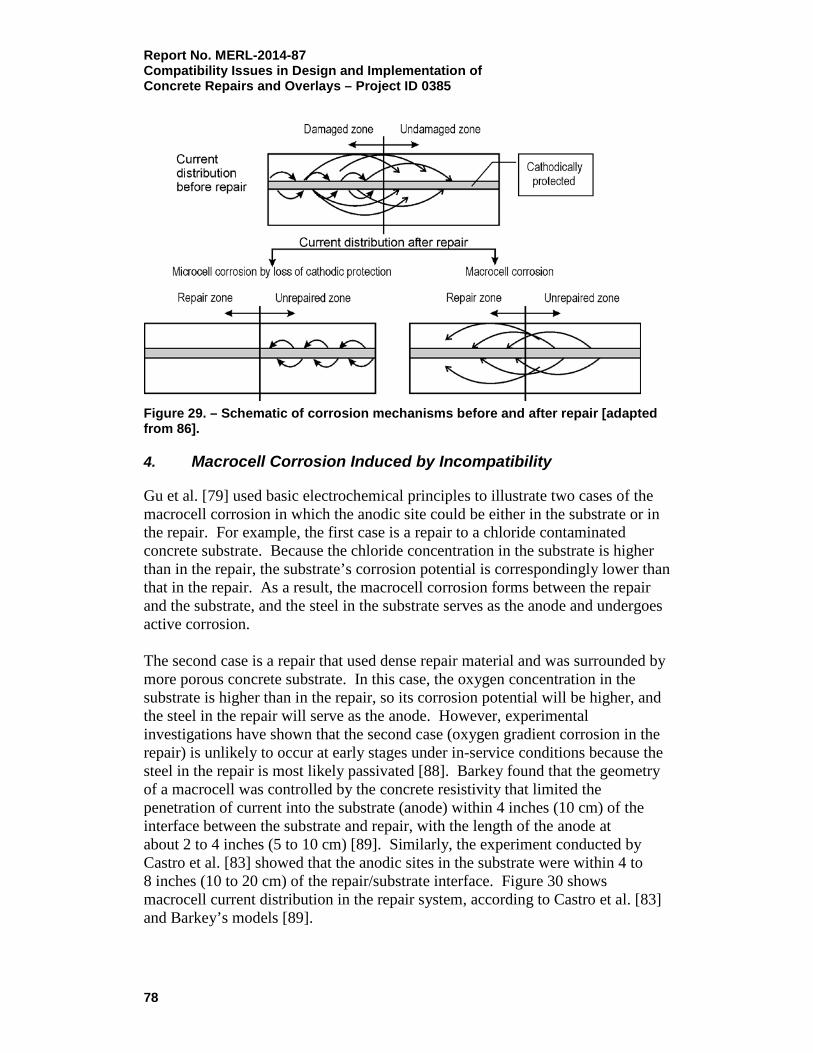
Report No. MERL-2014-87 Compatibility Issues in Design and Implementation of Concrete Repairs and Overlays – Project ID 0385
Figure 29. – Schematic of corrosion mechanisms before and after repair [adapted from 86].
4. Macrocell Corrosion Induced by Incompatibility
Gu et al. [79] used basic electrochemical principles to illustrate two cases of the macrocell corrosion in which the anodic site could be either in the substrate or in the repair. For example, the first case is a repair to a chloride contaminated concrete substrate. Because the chloride concentration in the substrate is higher than in the repair, the substrate’s corrosion potential is correspondingly lower than that in the repair. As a result, the macrocell corrosion forms between the repair and the substrate, and the steel in the substrate serves as the anode and undergoes active corrosion. The second case is a repair that used dense repair material and was surrounded by more porous concrete substrate. In this case, the oxygen concentration in the substrate is higher than in the repair, so its corrosion potential will be higher, and the steel in the repair will serve as the anode. However, experimental investigations have shown that the second case (oxygen gradient corrosion in the repair) is unlikely to occur at early stages under in-service conditions because the steel in the repair is most likely passivated [88]. Barkey found that the geometry of a macrocell was controlled by the concrete resistivity that limited the penetration of current into the substrate (anode) within 4 inches (10 cm) of the interface between the substrate and repair, with the length of the anode at about 2 to 4 inches (5 to 10 cm) [89]. Similarly, the experiment conducted by Castro et al. [83] showed that the anodic sites in the substrate were within 4 to 8 inches (10 to 20 cm) of the repair/substrate interface. Figure 30 shows macrocell current distribution in the repair system, according to Castro et al. [83] and Barkey’s models [89].
78

Report No. MERL-2014-87 Compatibility Issues in Design and Implementation of
Concrete Repairs and Overlays – Project ID 0385
Figure 30. – Macrocell current distribution in repair system according to: (a) Castro et al.’s (adapted from [83]), and (b) Barkey’s models (adapted from [89]).
5. Practical Implications
In present repair practices, macrocell corrosion caused by electrochemical incompatibility is used to explain corrosion of reinforcing steel in the concrete substrate near a repair area. At the same time, the possibility of microcell corrosion is overlooked, even when it might be a significant part of the total corrosion [80]. This, in part, is because the detection technique for macrocell corrosion cannot detect the presence of microcell corrosion. Because either microcell or macrocell corrosion (or both) can be the main reasons(s) for corrosion damage in the substrate near repairs, great attention should be paid to the underlying mechanisms in order to clarify the following issues:
1. Even if the macrocell is detected in repairs (often the case), the total anodic corrosion rate is unknown without measuring the coexisting microcell corrosion (see section II.A);
2. If the macrocell corrosion is not detected in repairs, it does not eliminate the corrosion risk in the substrate without measuring the microcell corrosion, which itself can exist and develop after a repair is completed.
Some available data allow for comparison of the densities of the macrocell and microcell corrosion activities. For example, Li and Yuan [88] showed that microcell corrosion in the chloride contaminated substrate (as recorded in their experiment setup) was approximately 1.1 milliamperes per square centimeter (mA/cm2), both before and after the repair, while the repair was at a rate of 2.0 mA/cm2. It can be seen that both the microcell corrosion, detected by the linear polarization method, and the macrocell corrosion, detected by zero resistance ampere meter, were very high.
79
Report No. MERL-2014-87 Compatibility Issues in Design and Implementation of Concrete Repairs and Overlays – Project ID 0385 Based on this, several cases are possible:
1. If the corrosion in the substrate is mainly the microcell corrosion induced by the loss of cathodic protection originally provided by the affected area, measures must be taken to depress the active corrosion in the substrate;
2. If the corrosion is mainly macrocell corrosion, any measures that can diminish the cathodic corrosion or increase the electrical resistivity of the repair material will diminish the anodic corrosion in the substrate;
3. If both corrosion mechanisms coexist, and the contribution from each is significant, multiple measures must be employed to stop the corrosion [88].
6. Influence of Corrosion Inhibitors on Compatibility
According to Vaysburd and Emmons [90], in concrete repair, completely relying on corrosion protection practices used in newly constructed structures, including the use of corrosion inhibiting admixtures, may become a part of the problem, instead of a solution. What happens when a corrosion inhibitor is added to the repair material? The local nature of the repair does not address the whole structure’s corrosion problem if chlorides or carbonation are widespread. Even if the local repair is adequate, with a necessary concentration of inhibitor, it can become a clean (non-corroding) cathodic area that stimulates increased corrosion around it. Repair procedures of this type are often characterized by early cracking and spalling in the original concrete adjacent to the “good” repairs. Another concern is maintaining the necessary concentration of the inhibitor in the repair phase. It is likely that the inhibitor does not remain in the limited repair area, but that it migrates with water and other ions, thereby reducing the necessary concentration. The porous structure and microcracks in the repair materials and concrete determine their ability to pass moisture under various gradients. The inhibitor solution can also move under a temperature gradient that occurs between different parts of the structure. Both moisture and temperature gradients determine the transport of water and other agents, via water, in the repair system. This flow can be significant when the structure is subjected to wetting and drying. In addition, it is highly likely that chloride ions from chloride contaminated existing concrete (by the transport mechanism described above) will move into the repair phase. Also, chloride ions from the exterior environment will penetrate into the repair phase. Chloride ions will react with the inhibitor and reduce its critical concentration. The inhibitor content and its fluctuations within the repair system determine its effectiveness. In the field, the inhibitor content will vary from place to place. Therefore, it is not possible to make an exact calculation of the effect of the inhibiting admixture on the service life of a repaired structure.
80

Report No. MERL-2014-87 Compatibility Issues in Design and Implementation of
Concrete Repairs and Overlays – Project ID 0385
To summarize, the authors challenged the effectiveness of using corrosion inhibitors for two main reasons:
1. The repair materials with corrosion inhibitors may simply form a cathodic area that stimulates corrosion around it in the substrate;
2. It may be difficult to maintain the effective concentration of inhibitors where they are really needed.
A 3-year field program by Cusson et al. [84] to monitor the performance of surface repairs containing corrosion inhibitors showed that the corrosion potential for the repair and substrate was around 100 to 150 millivolts (mV) and increased with time. It was, therefore, concluded that the risk of corrosion in the substrate would also increase with time. A comprehensive evaluation of premixed and surface applied corrosion inhibitors for concrete bridge deck patches and overlays, reported by the Virginia Transportation Research Council, in cooperation with the U.S. Department of Transportation and Federal Highway Administration [91], arrived at the following conclusions:
• Overlays with and without inhibitor treatments placed on slabs constructed with 15 lb/yd3 of chloride ion cracked and delaminated because of corrosion of the top mat of reinforcement. Half-cell potential data, tensile bond test data, and visual inspections of the reinforcement indicated no corrosion of the reinforcement. Use of corrosion inhibitors in the overlays and application of inhibitors to the surface of the concrete prior to placing the overlays provided no benefit;
• Overlays and patches with and without inhibitor treatments placed on and in slabs with 3, 6, and 10 lb/yd3 of chloride were performing satisfactorily at the time of evaluation. Half-cell potential data, tensile bond test data, and visual inspection of the reinforcement indicated no corrosion of the reinforcement. Further, these indicators do not show reductions in the tendency for corrosion that can be attributed to the inhibitors. More exposure time may show benefits that can be attributed to some of the inhibitor treatments;
• Overlays and patches with and without inhibitor treatments placed on and in five bridges were performing erratically. Corrosion probes placed in the overlays and patches showed mixed results. In some situations, the repairs with the inhibitor treatments performed better than the repairs without the treatments; while in other situations, the reverse was true. Corrosion was occurring in the majority of the repairs made with and without inhibitor treatments. The corrosion-inhibiting treatments did not seem to be reducing corrosion in the bridges and may be increasing it instead. More exposure time may show benefits that can be attributed to some of the inhibitor treatments;
81

Report No. MERL-2014-87 Compatibility Issues in Design and Implementation of Concrete Repairs and Overlays – Project ID 0385
• It is not obvious that corrosion was occurring in the full-depth slabs constructed with and without inhibitors to represent new construction. The slabs did not show signs of corrosion-induced cracking after 5 years of ponding. A longer period of ponding may show benefits that can be attributed to some of the inhibitor treatments;
• Topical applications of inhibitors did not affect the bond strength of the overlays;
• This project did not show any benefit from the inhibitor admixtures used in the patches and overlays and the topical applications made to the chloride-contaminated concrete surfaces prior to placing the patches and overlays.
7. Internal Environment in the Repair System
When conditions are evaluated prior to a potential repair, the existing concrete structure has certain transport mechanisms active. The removal of the damaged concrete and repair of reinforcing steel alter the existing internal environment and the transport mechanisms. The analysis of such changes, and their present and future effect on electrochemical behavior and degree of compatibility, are necessary components of a project’s durability planning phase. One important goal when evaluating conditions is to define the existing internal environmental conditions. These conditions, and the various degree of their severity, do not necessarily apply to the concrete structure as a whole; rather, they apply to elements and zones of the structure that can have radically different microconditions. The severity of the internal environment can be very different, depending on the exterior environment [4]. For example, the severity of exposure can be very different on the windward side of the navy pier than on the lee side. Similarly, areas of piers that are subject to salt water spray, but sheltered from rain, are exposed to a more severe chloride attack due to fewer washouts [92]. According to Vaysburd et al. [5], it is not a secret that the vast majority of deteriorated concrete structures and evaluation of their condition are related to corrosion of embedded reinforcing steel. However, the real causes of corrosion and deterioration, and their effects, can sometimes be quite complex. The difficulty arises not only from the makeup of the concrete itself but, to a large degree, from the influence of general and local climatic conditions. This usually involves an almost infinite combination of moisture, temperature, and wind, which creates a wide range of transport mechanisms of varying intensity. For instance, cyclic wetting and drying will lead to a buildup of an aggressive substance near the exposed existing concrete and repair surface. Similarly, with one wet surface, and the opposite surface exposed to drying, a one-way transport of water with dissolved substances will be created from the wet surface to the
82
Report No. MERL-2014-87 Compatibility Issues in Design and Implementation of
Concrete Repairs and Overlays – Project ID 0385
drying surface. This will result in increases in the concentration of the substances near the dry face due to evaporation. To begin analyzing what causes deterioration of existing concrete structures in the condition evaluation phase of the project (and later, to improve the durability [prolong the service life] of the structure in the durability planning phase), it is essential to understand the prevailing transport processes because without them, nothing can occur in a concrete structure and composite repair system. Without establishing the internal environmental condition and prevailing transport processes in an existing structure, it would be impossible to give necessary consideration to the possible deterioration and transport processes in a new composite repair system. Transport of substances through and within the structure is a complex process that consists of combinations of liquid flow through macrocrack and microcrack systems, capillary transport, diffusion, and osmotic effects. The exact contribution of each process to deterioration/distress must be considered in each particular situation. The effects of such variables as different locations within the structure, the chemical environment, the amount and distribution of cracks, and the temperature, moisture, and stresses need to be considered. The basic rule of thumb to promote long-lasting repairs is that reducing transport processes will normally improve durability.
8. Summary
Among the various factors affecting compatibility in concrete repair composite systems, the electrochemical compatibility is the most complex and critical factor for adequate performance of concrete repair jobs. It is difficult to predict how a repair to a concrete structure will affect its electrochemical activities because a variety of interconnected processes are involved, such as the nature of the repair materials, the condition of the substrate, the change in potentials, the exterior and internal (inside the system) environments and their interaction, and mass transport. The risk of corrosion developing or even accelerating due to electrochemical incompatibility between the “old” and “new” portions of the system is always present unless cathodic protection is implemented. Unfortunately, not enough current knowledge exists to reliably address the issue of electrochemical compatibility and, therefore, to predict the future service life of a repaired concrete structure. Vaysburd et al. [5] stated, “Beware of the experts who come up with an exact number of future service life of the repaired structure. After all, we are still subject to the mathematical and scientific laws of probability.” The design engineers have to do their best in the “durability planning” stage of the project, including an adequate consideration of electrochemical compatibility and related future service life issues.
83

Report No. MERL-2014-87 Compatibility Issues in Design and Implementation of Concrete Repairs and Overlays – Project ID 0385 E. Chemical Compatibility
Repair failures due to chemical incompatibility between a repair material and concrete substrate are very seldom reported in the literature and are almost ignored by engineers and scientists. However, chemical incompatibly is likely occurring more often than is realized, and it is usually a contributing factor to other major causes of repair failures. Emmons and Vaysburd [7] addressed the issue, stating that repair materials specified and used for repair jobs should be chemically compatible with the existing concrete substrate to avoid premature repair failures. Chemical compatibility properties to consider, according to the authors, may include alkali content, cement composition (tricalcium aluminate content, for example), chloride content, sulfates content, etc. All aspects of chemical compatibility must be considered in the selection of repair materials. For instance, when concrete repairs include potentially reactive aggregates, a repair material with low alkalinity must be specified. The reactivity of the repair material to reinforcing steel and other embedded metals, or to specific protective coatings or sealers applied over the surface repair, must also be considered. Repair materials with moderate to low pH may provide little protection to reinforcement. Moreover, certain repair materials are not compatible with waterproofing membranes required as protection following a repair. Therefore, the reactivity of the various repair materials with both the substrate and surface protection product should be considered. When encasing reinforcing steel of a chloride-contaminated structure in a repair material, the possible movement of chlorides within the repaired structure must be considered. As describer earlier, repaired areas that start out at a zero chloride level may, at some time, have high chloride content. When designing a repair, the actual parameters may differ depending on whether carbonation or chlorides are the most significant cause of corrosion and deterioration.
F. Aesthetic Compatibility
Some of the repair and restoration projects require matching the color, finish, and texture of existing concrete as closely as possible, which usually must be achieved without using surface coating to hide surface repairs. Repairs made to historic buildings, monuments, and architectural concrete usually require this type of compatibility. Such compatibility can be accomplished by using colored concrete, polished concrete, exposed aggregate concrete, etc. A new technology, automatic dispensing of liquid pigment to concrete, can offer an attractive solution. According to Forgey [93], it offers consistency, repeatability, cost effectiveness, and ease of use. A typical liquid dispensing system installation includes just four or five polyethylene bulk storage tanks, each holding up to 10,000 lb (4,500 kg)
84
Report No. MERL-2014-87 Compatibility Issues in Design and Implementation of
Concrete Repairs and Overlays – Project ID 0385
of liquid color. Much like a desktop printer, from these primary colors, thousands of colors can be ordered on demand, making managing inventory simple. When instructed by the system, the colors are pumped into a weigh vessel and then discharged into the truck mixer. Recipes for popular concrete colors are preprogrammed, so colors can be readily created through a pull-down menu. Users can also mix, match, and preview custom colors on screen, and the system will instantly convert the choice into a recipe ready for a concrete test batch. Because color draws attention, small shifts in color are readily visible on jobs. The precision offered by a liquid dispensing system therefore gives contractors and producers the confidence necessary to focus on concrete technology, not troubleshooting color issues. Architects can design and specify colored concrete knowing that the look they design will be achieved. Before beginning full-scale repairs, mockups should be produced, cured, and dried to confirm that they match the existing concrete. A rule of thumb is to wait at least 28 days before the review, but concrete continues to fade and change color over time, so the more cure time allowed, the better. All parties of the project team must agree that the color, finish, and texture of the repair are acceptable before moving forward with the project.
IV. Roadmap for Selection of Repair Materials This section of the report discusses and provides guidance on the process of specification and selection of repair materials based on their dimensional compatibility with the given concrete substrate.
A. General
The “Roadmap” in this context, can be defined as a set of requirements defining the dimensionally compatible, crack-resistant repair materials. The combination of properties and factors that are desirable to reduce the advent of cracking in a material can be described by the term “extensibility.” A material is said to have a high degree of extensibility when it can be subjected to deformations with very little cracking. An adequate, crack-resistance repair material should experience not only less shrinkage, but also have a relatively high degree of extensibility for cementitious materials (low modulus of elasticity, high creep, etc.). In general, high-strength and high early-strength materials are more prone to cracking due to greater shrinkage and lower stress relaxation. On the other hand, low-strength materials tend to crack less due to lower shrinkage and higher stress relaxation.
85

Report No. MERL-2014-87 Compatibility Issues in Design and Implementation of Concrete Repairs and Overlays – Project ID 0385 Material properties generally are the most important factors affecting extensibility. Material properties control the shrinkage strains that cause stresses and the relationship between stress and strain. Generally, mixtures should have low cement content and large aggregate content; large, well-graded crushed aggregate; and Type II cement. Also, it is helpful to use slow hardening cements, coarse cements, and low alkali content cements that result in a low early (1 to 3 days) modulus of elasticity, strength, and lower heat of hydration. It is necessary to point out, however, that it is very difficult, if not impossible, to compose a cementitious material with low shrinkage and high extensibility. Many factors that reduce the drying shrinkage will also tend to reduce the extensibility. For instance, an increase in coarse aggregate content will reduce the drying shrinkage but, at the same time, it will also reduce creep, stress relaxation, and extensibility. This example demonstrates the complexity of practical solutions, compared to purely theoretical solutions, for composing an extensible repair material. There are two basic problems involved with the applicability of repair materials and durability of the repair system as a whole:
• Proper formulation of the repair material mixture with the goal of producing a material with properties that meet the specific requirements. This is a material design and optimization problem;
• The compatibility of the materials in a composite repair system. This is a problem related to material selection and evaluation of the system behavior so they work together compatibly.
Cracking that is due to the restrained shrinkage of the repair material can be reduced by one, or a combination, of the follow factors:
• Low shrinkage of the repair material;
• High creep of the repair material;
• Low modulus of elasticity of the repair material;
• High tensile strength of the repair material. Today’s irony is that contemporary cement-based repair materials tend to be of high strength and contain a high amount of regular and high early-strength cementitious materials. It is obvious that crack resistance or extensibility of such materials is low because of increased drying shrinkage and modulus of elasticity on one hand, and reduction of both creep and relaxation on the other hand. This is why more expensive, so-called high performance repair materials are more vulnerable to cracking than their old-fashioned cementitious concrete material counterparts (3,000 lb/in2). It is obvious that the use of high-strength and, especially, high early-strength repair materials is not usually a good solution for corrosion protection and repair durability problems.
86

Report No. MERL-2014-87 Compatibility Issues in Design and Implementation of
Concrete Repairs and Overlays – Project ID 0385
B. Background
Vaysburd et al. [94] addressed the complex relationship between material properties and performance in concrete repair. Unquestionable progress has been made in the field of repair materials, but the material that has the required properties for a particular application is only one part of the complex system that makes up a concrete repair. A repair material has value only when it permits an engineered product (a concrete structure) to fulfill its intended use and function. In other words, any consideration of material needs, innovations, and performance must relate to the performance of the final engineering product (figure 31).
Figure 31. – Levels of influence on material performance [94]. Repairs correct deterioration or distress that affects a structure’s serviceability or aesthetics. In major structure rehabilitation, many repairs are on a scale where structural integrity becomes significant, and it is necessary to ensure the transfer of load between the concrete substrate and the repair. With such repairs, problems may arise quickly because of the different properties of the repair material and the concrete substrate. The differences between repair materials and existing concrete that can affect repair durability include:
• Shrinkage of the repair material relative to the concrete substrate;
87

Report No. MERL-2014-87 Compatibility Issues in Design and Implementation of Concrete Repairs and Overlays – Project ID 0385
• Thermal expansion or contraction differences between the repair material and concrete substrate;
• Differences in stiffness and Poisson’s ratio, causing unequal load sharing and strains resulting in interface stresses;
• Differences in creep properties of repair material and the concrete being repaired;
• Relative fatigue performance of the components in the composite repaired structure. Such differences may result in initial tensile strain that either cracks the repair material or causes debonding from the substrate.
Plum [95] discussed some of the critical compatibility of repair material properties for structural and “protective” (non-stress carrying) repairs. Both cement-based and polymer-based materials are addressed. Plum concludes the paper by stating: “Specifying the right properties is important for a successful application. Knowledge of compressive or flexural strengths is rarely a good guide.” Emberson and Mays [24] offered general requirements for “patch repair materials for structural compatibility” (table 11). Table 11. - General Requirements of Patch Repair Materials for Structural Compatibility [24]
Property Relationship of Repair Mortar (R) to Concrete Substrate (C)
Strength in compression, tension, and flexure R ≥ C
Modulus in compression, tension, and flexure R ≈ C
Poisson's ratio Dependent on modulus and type of repair
Coefficient of thermal expansion R ≈ C
Adhesion in tension and shear R ≥ C
Curing and long-term shrinkage R ≤ C
Strain capacity R ≥ C
Creep Dependent on whether creep causes desirable or undesirable effects
Fatigue performance R ≥ C
Chemical reactivity Should not promote alkali-aggregate reaction, sulphte attack, or corrosion of reinforcement in
the substrate
Electrochemical Dependent on permeability of patch material and chloride ion content of substrate
A literature review by Krauss and Rogalla indicates that the most significant material factors affecting sensitivity to cracking, and, therefore, to a large degree, of dimensional compatibility, are drying shrinkage, cement content, creep, elastic modulus, material temperature during placement, heat generated during hydration,
88

Report No. MERL-2014-87 Compatibility Issues in Design and Implementation of
Concrete Repairs and Overlays – Project ID 0385
and water content [96]. Aggregate type, mineral additions, admixtures, and cement type also influence cracking. General recommendations from the literature, concerning concrete material properties to reduce cracking, include using the following:
• Low amounts of cement;
• Good quality, low-shrinkage aggregates;
• Air entrainment;
• Low drying shrinkage concrete;
• Moderate placement temperatures;
• Means to reduce hydration temperature rise;
• Low water content (water-cement ratio between 0.41 and 0.45);
• Type II cement. Several transportation agencies suggested that shrinkage-compensating cement reduces deck cracking. However, results of laboratory and field investigations related to shrinkage-compensating cement and early cracking are mixed. There is controversy on the use of retarders, accelerators, fiber reinforcement, fly ash, and silica fume, and their roles in deck cracking. Further research is needed. Design and construction factors for each material are described in detail in the National Cooperative Highway Research Program (NCHRP) report [96]. One of the design conclusions of the study was that “the use of epoxy-coated bars increased the width of deck cracks.” As to the construction practices, the report concludes that: “weather during construction affects cracking. Adverse conditions include high winds, extreme low and high temperatures, and low humidity.” The following is recommended to reduce shrinkage in a given environment:
• Reduce the paste volume and the total amount of water in the concrete;
• Maximize the amount of aggregate;
• Use Type II cement;
• Use aggregate with low-shrinkage properties. The longer periods of moist curing do not necessarily decrease the final drying shrinkage, but they may reduce the shrinkage rate, especially for high-strength mixes. Results of the laboratory and field investigations were correlated in an attempt to evaluate how individual material properties, or combinations of properties, affect the potential for cracking of field repairs [97, 98, 99]. The study developed
89

Report No. MERL-2014-87 Compatibility Issues in Design and Implementation of Concrete Repairs and Overlays – Project ID 0385 performance criteria for the selection and specification of dimensionally compatible, cement-based repair materials, which are presented in table 12. Table 12. – Performance Criteria for Repair Materials (adapted from [97])
Property Test Method Requirement Tensile Strength, minimum 28 days CRD-C 164 2.8 MPa (400 psi)
Modulus of elasticity, maximum ASTM C469 24 GPa (3.5 x 10⁶ psi)
Coefficient of thermal expansion CRD-C 39 Compatible with existing concrete
Drying shrinkage, maximum 28 days 1 year
ASTM C157 (Modified. For modifications to the standard,
see “Data Sheet Protocol.”
0.04% 0.10%
Restrained shrinkage cracking - Cracking - Implied strain at 1-yr age, max.
Ring Method. For test description, see “Data Sheet Protocol.”
No cracks within 14 days
0.10% The reports and referenced publications in the reports concluded that the proposed performance criteria should be considered a general profile of desired material properties. The relative importance of individual properties will vary, depending on the anticipated application and service conditions for a given repair. Therefore, the requirements should be modified as appropriate for a specific repair. Material data sheets from numerous manufacturers and suppliers in North America were studied and evaluated. The evaluation revealed that these data sheets provide engineers very limited, and often misleading, information on which to base the selection of materials for a specific project. The study on performance criteria proposed a standard material data sheet that includes requirements for data on basic material compositions, properties, and advantages and limitations of the material under specific applications, and service conditions are presented in [100, 101]. In addition, a standardized protocol for reporting properties, characteristics, and description, of cement-based repair materials was developed by the ACI. They issued ACI 346.3R-09, Guide for Cementitious Material Data Sheet [102], which was a major milestone in the concrete construction field. It requires providing information on material in a standardized, logical, and consistent format so that repair materials can be appropriately specified and selected. The protocol defines important properties and how to test for these properties. Unlike a specification, performance criteria are not listed. It is left to the specifier to choose the performance criteria based on the properties of the substrate concrete, the application constraints, and the environment of the installation to achieve compatibility. A discussion of the relevance, interpretation, and suggested limiting values of many types of concrete materials has been published in a related document, ACI 546.3R-14 Guide to Materials Selection for Concrete
90

Report No. MERL-2014-87 Compatibility Issues in Design and Implementation of
Concrete Repairs and Overlays – Project ID 0385
Repair [35]. Figure 32 shows the durability related properties addressed in the protocol.
Figure 32. – Durability-related properties of concrete repair materials as listed in the protocol in ACI 546.3R-14 [35] (1 mm = 0.04 inch; °F = 9/5 × °C + 32). The implementation of the ACI 546.3R-14 Guide will unquestionably improve the quality of design specifications and, accordingly, the quality of repair projects, which is crucial to the sustainability of concrete structures. There is presently, however, a serious problem with the implementation of the guide into the practice [103]. The next critical issue is for repair material manufacturers to test their products according to the protocol and ensure that their quality control processes are suitable to make any given product consistently.
91

Report No. MERL-2014-87 Compatibility Issues in Design and Implementation of Concrete Repairs and Overlays – Project ID 0385 C. Roadmap
Based on extensive literature review and practical experience, the critical basic composition rules and the material’s sensitivity to cracking are summarized in Tables 13 and 14 respectively. Table 13. – Roadmap – Materials Composition Controlling Rules (adapted from [104])
Parameter
Moderate to Low early strength
Moderate compressive strength
Low early modulus of elasticity
Optimum amount of good quality aggregates
Pozzolans (fly ash, slag)
Type II cement
Minimum paste volume
Table 14. – Roadmap – Material’s Sensitivity to Cracking Control Parameters (adapted from [104])
Parameter Effect
Major Moderate Minor
Drying shrinkage X
Modulus of elasticity X
Creep X
Compressive strength X
Early strength X
Paste content X
Cement content and type X
Aggregate content, type and size X
Coefficient of thermal expansion X
Water to cementitious materials ratio X
Accelerating admixtures X
Plasticizers X
Silica fume X
Fly ash X
Slag X
Water content X
Slump (within typical ranges) X
92
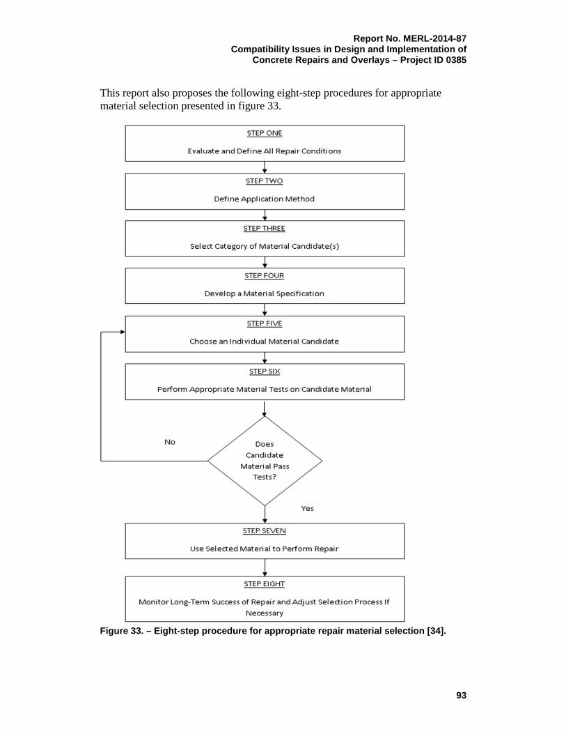
Report No. MERL-2014-87 Compatibility Issues in Design and Implementation of
Concrete Repairs and Overlays – Project ID 0385
This report also proposes the following eight-step procedures for appropriate material selection presented in figure 33.
Figure 33. – Eight-step procedure for appropriate repair material selection [34].
93

Report No. MERL-2014-87 Compatibility Issues in Design and Implementation of Concrete Repairs and Overlays – Project ID 0385 V. Relationship Between Bond and Compatibility
for Enhanced Performance This section of the report emphasizes bond in composite repair/overlay systems. Bond is the foremost factor in repair systems, provided that a durable repair material is used, electrochemical computability is achieved, the residual concrete substrate is sound, and its durability is synonymous with the durability of the whole composite system.
A. Bond Performance and Its Role in Repair Durability
Concrete repair is a composite system of materials. In composites, the bond between the individual components is the most critical for overall viability. The durability of the bond in repair systems can be defined as a lasting interfacial coexistence of repair and existing phases. High initial bond strength is generally not an indication of bond durability. Assuming the properties of the components are good, any improvement of the bond will improve the properties of the composite system [10]. Achieving an adequate lasting bond between repair materials and existing concrete is a critical requirement for durable surface repairs. The bond at the interface between the two constituents, or phases, is likely to be subject to considerable stresses from volume changes, freeze-thaw cycles, the force of gravity, and, sometimes, impact and vibration. The stress conditions that develop at the bond line will vary considerably, depending on the type and use of the structure. For example, the bond on a bridge deck overlay may be subject to shear stress in conjunction with tensile or compressive stress induced by shrinkage or thermal effects, as well as to compression and shear from service loads. Repairs that are subject to shear stresses at the bond line are capable of stress resistance not only by bonding mechanisms, but also by aggregate interlock mechanisms, which add greatly to shear bond capacity. It is essential that the repair material achieves a strong bond to the substrate and that subsequent stresses not be severe enough to cause debonding. Repairs that have bond lines in direct tension have the greatest dependence on bonding. Repairs and bonded concrete overlays have often experienced serious performance problems, which mainly manifest as cracking and/or debonding. These failure mechanisms are largely a result of differential volume changes (or, in other words, dimensional incompatibility between substrate and repair). The repairs and overlays are subjected to shrinkage and thermal strains, while the substrate’s deformations are usually negligible. The restrain to repair deformations causes direct stresses. Debonding is of great concern for the durability of composite repair system because it leads to delamination and spalling and, hence, results in failure. The mechanisms of cracking and
94
Report No. MERL-2014-87 Compatibility Issues in Design and Implementation of
Concrete Repairs and Overlays – Project ID 0385
debonding are complex and mainly depend on compatibility factors, such as material parameter and the degree of restraint governed by the structural characteristics of the existing substrate, and, of course, on the environmental influences. The most important repair material parameters, as described in section IV above, are tensile strength, elastic and visco-elastic properties, and volume changes caused by shrinkage. Development and magnitude of interface bond strength also depends greatly on substrate surface preparation and workmanship during repair application [35, 105]. Unfortunately, for concrete repair works, no reliable comprehensive design recommendations are available for the practitioner [106]. The scope of this section of the report is limited to cement-based material repairs. Resin-based materials, as well as fiber reinforced and self-compacting concretes, were not examined.
B. Bond Properties
The characteristics of adhesion, or "bond," can be perceived from two different angles: (1) the conditions and kinetics of joining two materials, taking into account different bond mechanisms; and (2) the quantitative measure of the magnitude of adhesion, usually expressed in terms of stress or energy required to separate the two materials. Available information on overlay bond strength commonly refers to the stress required to separate substrate and overlay [107]. The term "adhesion" describes the condition in the boundary layer between two connecting materials with a common interface. Adhesion mechanisms can be divided basically into mechanical interaction, thermodynamic mechanisms, and chemical bonding [108]. Mechanical adhesion in repaired concrete members relies on the hardening of the overlay inside the open cavities and asperities of the substrate surface and physical anchorage resulting therefrom. Capillary absorption plays an important role in the anchorage effect because it draws material paste into open pores and small cavities of the substrate. It is dependent on the substrate moisture condition. Mechanical bond may be assisted by contact friction between substrate and repair in areas where the actual adhesion is inadequate. This is described by shear friction models, as discussed in the literature [109, 110]. It is important to note that mechanical adhesion in tension differs significantly from mechanical adhesion in shear. For example, a high interface roughness may improve shear bond strength, whereas tensile mechanical bond strength primarily depends on vertical anchorage in pores and voids, as presented in figure 34.
95

Report No. MERL-2014-87 Compatibility Issues in Design and Implementation of Concrete Repairs and Overlays – Project ID 0385
Figure 34. – Schematics of mechanical shear and tensile bond between substrate and overlay resulting from interlock mechanisms [106]. The information presented above is important for making the correct choice of bond strength test methods for given test parameters. Differential volume changes between substrate and repair, resulting from temperature gradients or shrinkage, cause both shear and tensile stresses at the interface. In structural design, tensile stresses perpendicular to the interface are rare. By contrast, interface shear stresses occur frequently in composite elements (e.g., those caused in composite slabs subjected to bending stresses). Standards and specifications for concrete repair define bond strength commonly in relation to tensile strength alone, which, in consideration with the information above, appears problematic [105]. When specifying and/or evaluating bond strength values, it is important to consider the dominant interface stress condition experienced by the actual structure [111]. Talbot et al. [112] investigated the influence of different interface textures and concluded that smooth surfaces, as well as sandblasted surfaces, experienced a significant loss of bond strength with time. On one hand, adhesion is defined as a process through which two bodies are brought together and attached (bonded) to each other in a way that requires external force or thermal motion to break the bond. On the other hand, we can examine the process of breaking a bond between bodies that are already in contact. In this case, as a quantitative measure of the intensity of adhesion, we can take the force or the energy necessary to seperate the two bodies. Therefore, adhesion has two different aspects, according to whether our interest is mainly: (1) in the conditions and the kinetics of contact, or (2) in the separation process. The intensity of adhesion will depend not only on the energy that is used to create the contact, but also on the interaction existing in the interface zone [113]. The mechanism of adhesion can be classified in two phases, as presented in figure 35. All bond mechanisms act on the true surface area, as opposed to geometric surface area and the contact surface area (figure 36). A higher degree of roughness increases the true surface area. The effective surface describes the actual covered area and depends, to a great extent, on the consistency, compaction, and thermodynamic properties of the fresh concrete overlay. For quantification of bond strength, the failure load is usually divided by
96
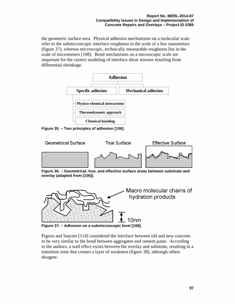
Report No. MERL-2014-87 Compatibility Issues in Design and Implementation of
Concrete Repairs and Overlays – Project ID 0385
the geometric surface area. Physical adhesion mechanisms on a molecular scale refer to the submicroscopic interface roughness in the scale of a few nanometers (figure 37), whereas microscopic, technically measurable roughness lies in the scale of micrometers [108]. Bond mechanisms on a microscopic scale are important for the correct modeling of interface shear stresses resulting from differential shrinkage.
Figure 35. – Two principles of adhesion [106].
Figure 36. – Geometrical, true, and effective surface areas between substrate and overlay (adapted from [106]).
Figure 37. – Adhesion on a submicroscopic level [108]. Pigeon and Saucier [114] considered the interface between old and new concrete to be very similar to the bond between aggregates and cement paste. According to the authors, a wall effect exists between the overlay and substrate, resulting in a transition zone that creates a layer of weakness (figure 38), although others disagree.
Physico-chemical interactions
Thermodynamic approach
Chemical bonding
Specific adhesion Mechanical adhesion
Adhesion
97

Report No. MERL-2014-87 Compatibility Issues in Design and Implementation of Concrete Repairs and Overlays – Project ID 0385
Figure 38. – Transition zone between substrate and overlay, according to Pigeon and Saucier [114]. Van Mier [115] has summarized existing knowledge on interfaces between aggregates and cement matrix. The bond mechanisms between aggregate and cement paste depend largely on the porosity of the aggregate. Generally, a thin layer of CH forms at the physical boundary between aggregate and cement matrix, followed by a relatively open layer containing oriented CH crystals, ettringite, and CSH. This so-called contact or transition layer has a very high porosity. Van Mier explains this high porosity with absorption of mixing water at the surface of aggregate particles, which increases the effective w/c ratio. According to Van Mier’s research, fracture surfaces generally exist not directly at the physical boundary between aggregate and matrix, but slightly removed from the interface in the porous transition zone. These mechanisms have not yet fully been investigated in relation to interface between concretes of different ages, but they may be useful for characterizing fundamental bond properties in composite members. Misra et al. [116] found a relation between air permeability at the interface and bond strength, which could be linked to the effects described above. However, the statement that the transition zone “creates a layer of weakness,” in the opinion of others, is only justified when the surface preparation for repair is inadequate. Otherwise, the transition zone may be a zone of strength, rather than weakness. Emmons and Vaysburd [7] presented an idealized model of a surface repair as a three-phase composite system consisting of existing concrete, repair material, and a transition zone between them (figure 39).
98

Report No. MERL-2014-87 Compatibility Issues in Design and Implementation of
Concrete Repairs and Overlays – Project ID 0385
Figure 39. – Idealized model of a surface repair system [7]. A possible macroscopic characterization of the quality or degree of adhesion is obtained by the introduction of a transition zone along the geometrical interface between the adhesive and adherent. The thickness of the transition zone is the sum of the lengths in the adherent and the adhesive zones, where interactive forces of any nature change the mechanical nature of the original continuum [117]. Adherence between a repair and the existing concrete in a mature composite repair is a case of adherence between two solids. One of the solids (the repair material) formed as a result of setting and hardening of a semi-liquid substance, which was placed on the prepared surface of a second substance in a solid state (existing concrete). The following major factors that influence the formation of the transition zone and degree and durability of bond are:
• Properties of substrate concrete and the prepared surface;
• Properties of repair material;
• Absorption of the substrate;
• Adhesion and adequacy of adherence of the repair material in both uncured and cured states;
• Environmental conditions. The repair material and concrete substrate, when viewed as a classical glued connection, can be considered as a "contact couple" in which the repair acts as the glue. In this case, the bond strength can be seen as the result of mechanical bond, pure adhesion, cohesion, and contraction of the repair material. The first three factors increase the bond strength, and contraction decreases it. Adhesion and cohesion are two interconnected parts of the process of forming of the contact zone. However, the most important component of bond strength for concrete repair is the adhesion. The mechanical anchorage of the repair is related to the roughness and the porosity of the substrate. When estimating the effect of a substrate on bond, not only its roughness, but also the size and form of the
99

Report No. MERL-2014-87 Compatibility Issues in Design and Implementation of Concrete Repairs and Overlays – Project ID 0385 protrusions must be taken into account. In the case of extended, but gentle, unevenness, an increase of the bond strength only occurs with an increase of the actual contact area. The specified properties of the repair material (e.g., consistency, method of compaction, etc.) have a considerable influence on the mechanical anchorage, the adhesion, and the bond strength. The amount of the bond strength between the concrete and the repair material also depends, to a great extent, on the cohesion of the repair material, which is governed by the strength of the binder (cement, fly ash, etc.), its mineralogical components, and by curing condition [10]. The effects of an interfacial transition zone in repairs and bonded overlays are considered important because bond is generally described as “interface” bond strength. However, definition of interface bond strength should concentrate not only on interface properties, but also on repair and substrate material characteristics and their compatibility.
C. Bond Test Methods
The results of interface bond tests depend, to a large extent, on the test method used, which is often not considered in the interpretation of bond strength measurements. Common bond test methods include interface shear, torsion, and tension tests, and a wide range of possible test setups have been developed for laboratory testing. Interface shear strength values obtained by different test methods may differ substantially because test results depend on specimen size, test setup, loading rate, etc. Li et al. [118] investigated the size effect in bond tests and concluded that smaller specimen sizes led to larger bond strength in prism splitting tests. A comparison of test results obtained with different test methods, or even results obtained by different researchers using the same test method, is, therefore, problematic. Relating interface shear and tension tests is questionable because both bond mechanisms have substantially different characteristics; however, Silfwerbrand [119] and Delatte et al. [120] indicated a correlation between the two test methods. The latter measured a mean ratio (shear bond divided by tension bond) of 2.0. Silfwerbrand found a ratio between torsional shear bond strength and tensile pull-off strength in the range of 2 to 3. Based on the results from several studies, shear bond strength is generally higher than tensile bond strength. However, there is no agreement on the magnitude of the difference. The reported mean ratio (shear bond strength divided by tensile bond strength) ranges from 1.2 to 2.4 inches (30 to 60 mm) according to different studies that were reviewed. That range is obviously too wide for satisfactorily converting the pull-off test results to shear bond strength. From an exhaustive study by Bissonnette et al. [111], the main findings can be summarized as follows:
100

Report No. MERL-2014-87 Compatibility Issues in Design and Implementation of
Concrete Repairs and Overlays – Project ID 0385
• When considering the relationship between interfacial pull-off bond and shear bond strengths in composite repair overlay systems, the test results do not exhibit the same trends as are often reported or described in the literature (in fact, reported hard data comparisons are extremely scarce);
• No general correlation could be established because the various surface preparation techniques result in different types of profiles and induced defects. The combination of these parameters influences pull-off bond and shear bond strength measurements in different ways;
• Relating interface shear and tension test results in a highly heterogeneous medium, such as a concrete composite, is, in fact, questionable because both rely on different combinations of bond mechanisms, which are affected to varying degrees by the interface and substrate characteristics (adhesion, friction, interface roughness and geometry, mechanical integrity of the substrate, etc.);
• The pull-off tensile bond test is the only test commonly used in practice because the equipment is widely available, and it is relatively easy to carry out in the field. Shear (torsional) tests may also be performed onsite, but they are very seldom used for a number of reasons; the most significant reason is probably the absence of specification guidance;
• The tensile pull-off test itself has a number of potential shortcomings, which must be considered in the analysis of results. The first problem, addressed earlier, is possible misalignment of the testing apparatus, which leads to uneven stress distributions and can potentially exert a significant influence on measured strength values. A second problem that is commonly encountered with tensile pull-off tests is that failure often occurs outside the interfacial zone, either in the repair material or within the existing substrate. When such a failure occurs, the recorded maximum stress merely represents a lower value for interface bond strength. A third problem encountered with the pull-off test is that the coring operation (part of the test procedure) may damage the interface between the repair and the substrate, which is likely to reduce the recorded pull-off strength;
• Results of pull-off measurements under field conditions often show a large scatter of results, which makes it difficult to interpret the measurements in relation to actual test parameter [121].
The schematics in figure 40 show existing test methods for evaluating the interface bond strength between repair materials and concrete substrates.
101

Report No. MERL-2014-87 Compatibility Issues in Design and Implementation of Concrete Repairs and Overlays – Project ID 0385
Figure 40. – Schematics of various test methods to determine interface bond strength [106].
D. Factors Affecting Bond Strength
1. Condition and Texture of the Substrate
According to Vaysburd et al. [121], “the process of concrete surface preparation for repair is the process by which sound, clean, and suitably roughened surface is produced on concrete substrates.” The workmanship is of utmost importance. Besides removal of unsound concrete and all foreign materials that may disturb bond development, the process also covers the opening of the substrate concrete pore structure.
a. Temperature The concrete substrate temperature at the time of repair and overlay placing was found to have a significant effect on shear bond strength development [120].
102

Report No. MERL-2014-87 Compatibility Issues in Design and Implementation of
Concrete Repairs and Overlays – Project ID 0385
While cold substrates (4 °C, 40 °F) resulted in lower initial bond strength, higher long-term bond strength was achieved in comparison with that of substrates at higher temperatures (21 °C and 38 °C [70° and 100 °F]). This effect is caused by hydration of the cement paste. Low temperatures generally slow down the hydration rate. At slow hydration rates, the hydration products have sufficient time to diffuse uniformly throughout the material, which, consequently, positively affects later age strength.
b. Moisture Condition The substrate moisture condition may have a significant influence on bond strength. A dry, "thirsty" concrete surface tends to suck water from the overlay, which may result in weak interfacial repair layer and low bond strength (figure 41-A). A surface that is too wet tends to dilute the repair material at the interface and increases the water/cement ratio, hence leading to low material strength, increased shrinkage, and low bond strength. Water in open pores further prevents the interlocking effect (figure 41-B). The substrate concrete should, therefore, be saturated but surface dry (figure 41-C).
Figure 41. – Critical moisture conditions of the substrate surface [105]. The influence of the substrate surface moisture condition on bond strength has been investigated in many studies. In general, the opinions on the effects of substrate moisture differ significantly between individual researchers and engineers [114]. For example, Li et al. [118] measured the bond strength of repaired specimens after freeze-thaw cycles and found that different repair materials correspond to different
103

Report No. MERL-2014-87 Compatibility Issues in Design and Implementation of Concrete Repairs and Overlays – Project ID 0385 optimum interface moisture conditions at the time of casting. Zhu [122] has found experimental signs of optimal moisture, but the effects were so insignificant that it was difficult to discern between the actual test parameter and the scatter of test results. Bissonnette et al. [111] concluded that a saturated surface dry condition of the substrate prior to application of cementitious repair materials is usually recommended. In repair practice, this underlies the “layman’s” tendency to avoid problems, rather than achieve the most effective bond. Various investigators came to the conclusion that different substrates and repair materials may require different interface moisture conditions at the time of casting to achieve optimum interfacial bond. The problem is that, presently, there is no test method to determine the optimum moisture condition for a given combination of substrate and repair material. Water is one of the critical factors influencing bond development between concrete and repair materials: it may accumulate at the interface or migrate through the materials as a result of mechanical (i.e., gravity), chemical (i.e., hydration) or physical (i.e., temperature gradients) driving forces. Different moisture transport parameters affect the formation and behavior of the repair interfacial zone. Diffusion and permeability coefficients affect moisture transport, and they are influenced by different forms of water interaction:
• First, moist conditioning of the substrate before the application of the repair system is a key consideration. Partial or total saturation of a concrete substrate is a common situation in repair works. Excess water along the interface may prevent adhesion to the repair system, with regard to polymer concrete, polymer modified portland cement concrete, or portland cement concrete [123];
• Second, water or aqueous solution movements may appear [124], due to migration and infiltration along the interface [125], or due to diffusion and capillary absorption from the zones to be repaired [123]. Resistance to these water movements will directly depend on the quality of the materials (i.e., the water to cement ratio, porosity, etc.).
The study reported by Bissonnette et al. [111] concluded that, due to the complexity of the use and multiplicity of influencing factors affecting the evaluation of optimum moisture condition, the evaluation is not complete. The findings demonstrate the effect of water in the substrate concrete superficial zone and the difficulty encountered in reliably evaluating the actual saturation level. For the repair systems considered in the study, it appears that optimum saturation levels for repair bond strength would lie somewhere between 55 to 90 percent. Clearly, however, additional work is required to identify a methodology that could be used in field applications and, furthermore, to assess more precisely and reliably what the optimum moisture ranges are for cement-based repair materials.
104

Report No. MERL-2014-87 Compatibility Issues in Design and Implementation of
Concrete Repairs and Overlays – Project ID 0385
c. Concrete Carbonation According to Schrader [126], carbonation of the substrate can result in a soft surface and dusting, which may cause poor bond strength if an overlay is applied. Similar test results were obtained by Gulyas et al. [128], who found that substrate carbonation can decrease bond significantly. By contrast, Block and Porth [129] found that substrate carbonation does not affect pull-off bond strength. These contradicting results show the problems inherent in interpreting bond test results for complex systems in terms of a single test parameter. The actual differences in results can be explained by likely differences in surface preparation, repair material application, and curing.
d. Fresh Repair Material Properties The fresh repair material properties are important, both for early age bond strength development and bond durability. Workability and compaction of the freshly placed overlay influence the ability to fill open cavities and voids on the substrate concrete surface and, therefore, to determine the effective contact area between the two composites. A relatively fluid overlay (made that way with additives and not purely with water) further enhances capillary suction in the substrate (as long as it is not too wet), which improves physical anchorage in substrate surface pores and cavities. Horizontal repairs, for example, on pavements or bridge decks, and large application areas on vertical and overhead surfaces, may be carried out with concrete of high fluidity. Self-leveling mortar applied for overhead repair using formwork was found to have very good bond properties in terms of its ability to fill cavities at the interface [130]. The fact that good anchorage can be achieved without the effects of gravity implies that capillary suction of the old concrete plays an important role in bonding mechanisms. In contrast to the above example, small surface repairs are commonly made with premixed, relatively stiff mortars, which are applied with a trowel. This leads to a smaller contact area between substrate and overlay, and a lower capillary suction of the substrate, compared to overlays of higher fluidity, thus resulting in lower mechanical and chemical bond strength. For these kinds of mortars, bonding agents might be helpful to improve adhesion [105]. Shotcrete, which is economical only for very large repair areas, is applied to the concrete substrate using a high amount of energy. The mixture of fine aggregate and paste is pressed into the open pores and surface texture of the substrate. Following layers then add on to this base layer, with the coarse aggregate embedded in the initial thin layer of mortar. Lacombe et al. [130] used a microscope to visually assess the interface the between shotcrete and old concrete. The quality of bond appeared to be so good that it was almost impossible to see the difference in microstructure between the shotcrete and old concrete. Bond properties between the substrate and shotcrete may depend on the nature of the shotcrete and, most importantly, on workmanship. Talbot et al. [112] performed
105
Report No. MERL-2014-87 Compatibility Issues in Design and Implementation of Concrete Repairs and Overlays – Project ID 0385 bond tests on specimens repaired with different types of shotcrete and concluded that mix composition, such as wet or dry shotcrete, has little influence on bond durability. The above discussion indicates that repair workability plays an important role for bond strength. However, even with relatively stiff overlays, good bond can be achieved if the overlay is applied with sufficient pressure and workmanship is good.
e. Hardened Repair Material Properties The compressive strength of the repair material usually does not influence the bond strength significantly. However, tensile strength is important because it affects crack development and, therefore, the formation of boundary conditions that may support the initiation of debonding. Delatte et al. [120] found that an increase in early age concrete strength increased both tensile and shear bond strength significantly. Repair permeability may influence bond durability; for example, very impermeable overlays result in stresses at the interface when moisture from the substrate cannot migrate through the overlay [127]. The above statement is an illustration of the permeability incompatibility that affects the bond in composite repair systems [8]. The addition of polymers to cementitious repair mortars was found to result in better bond characteristics on specimens subjected to extensive temperature cycles [131]. Li [132] states that the addition of fly ash to overlay mixes results in lower short-term, but higher long-term, bond strength, which he links to the effects that the addition of fly ash has on the rate of hydration. He further states that fly ash or silica fume in the overlay can improve the microstructure of the interface transition zone and, hence, increase bond strength. Similar test results were reported by Kuroda et al. [133], who found significant enhanced bond strength at both 7 and 28 days when a high lime (CaO) content fly ash was added to the overlay mix.
f. Short-Term Bond Properties The development of early age bond strength is important for the structure's ability to withstand interface stresses induced by early age differential movement between substrate and overlay. For pavement and bridge deck overlays and repairs, high early bond strength is usually required due to traffic and live load. According to Delatte et al. [120, 134], bond strength develops rapidly after placement, similar to concrete compressive strength development. In their studies, the authors suggest a concrete maturity approach, which characterizes bond strength development in relation to the concrete's rate of hydration, rather than its
106

Report No. MERL-2014-87 Compatibility Issues in Design and Implementation of
Concrete Repairs and Overlays – Project ID 0385
age. Similarly, Silfwerbrand [135] concluded from pull-off tests that bond strength development at early ages is rapid. Carter et al. [136] stated that bond strength develops more fully in the center of an overlay because the boundaries are especially subjected to cyclic stresses related to differential temperature and moisture content. In general, short-term bond properties can be used as indication of the quality of the prepared substrates, workmanship, compatibility of materials (dimensional compatibility), curing, and service conditions at the time of application.
g. Long-Term (Durability) Bond Properties The durability of the bond in composite repair systems can be defined as lasting interfacial coexistence of the existing and repair phases [10]. Most studies documented in the literature focus on the quality of bond at early ages. However, factors influencing long-term bond strength are most important for the performance of composite members. Pigeon and Saucier [114] state that, although the durability of bond between old and new concrete is influenced by many factors, differential shrinkage is the most important aspect. In their study, they subjected composite specimens to a range of aging treatments and found that simple air drying was the main cause of deterioration. By contrast, freezing and thawing had a positive effect, which was attributed to the effects of ongoing hydration that was facilitated by water used in the test procedure. Li et al. [118] found that specimens subjected to 300 freeze-thaw cycles had similar bond strength as air-cured specimens. A common way to assess bond durability is to test long-term bond strength in actual structures. Carter et al. [136] state that well-designed bridge deck overlays can be expected to provide more than 30 years of service life if they are placed and cured correctly. Langlois et al. [137] tested pull-off strength on a road repair overlay and concluded that as long as good quality concrete is used and workmanship is good, bond durability can be achieved regardless of the type of repair mortar or surface preparation. Repaired beams and columns with well-bonded overlays were shown to have structural capacities similar to those of monolithic members [138]. Okada et al. [139] found that differential shrinkage greatly affects cracking behavior, but does not influence flexural strength of composite beams, which indicates that bond strength is not necessarily affected, even if restrained shrinkage exceeds tensile overlay strength. Talbot et al. [112] investigated the influence of different interface textures and concluded that smooth surfaces, as well as sandblasted surfaces, experienced a significant loss of bond strength with time. On the contrary, surfaces that were roughened mechanically and, subsequently, sandblasted had good bond durability because high interface roughness, as is commonly achieved with mechanical methods, improves the resistance against interface shear stresses resulting from differential shrinkage.
107

Report No. MERL-2014-87 Compatibility Issues in Design and Implementation of Concrete Repairs and Overlays – Project ID 0385 The most important material parameters with respect to repair and bonded overlay resistance to cracking and/or debonding are shrinkage, creep relaxation, and modulus of elasticity (dimensional compatibly-related properties). Failure modes and bond strength, as well as long-term performance, show that repair and overlays to existing structures are a three-phase composite system with an interface transition zone between existing substrate and repair/overlay materials, as described earlier in this report. Long-term bond strength and durability, to a large degree, depend on the quality of the material in the transition zone, on the macro-mechanical interaction in the interface transition zone, and on the repair/overlay shrinkage. Thus, the long-term durability of the composite system will depend on compatibility between the concrete substrate and the repair material [73].
E. Conclusions: Compatibility and Bond in Composite Repair Systems
When compatibility issues are properly addressed in repair systems, durability of the bond is achieved, as it ensures a lasting coexistence of the repair material and substrate concrete. Incompatibility issues cause premature debonding and repair failures. Unfortunately, at the present time, there is much confusion, many misconceptions, and misleading guidance concerning compatibility of repair and the substrate concrete. These issues negatively affect the design, specification, implementation, and, as a result, service life of concrete repairs and overlays. Development of reliable guidelines that address compatibility, with special emphasis on the factors related to dimensional compatibility issues, is needed for the repair industry to evolve as an engineering discipline.
VI. Recommendations and Needs for Further Research and Development
This report has taken a wide approach and addressed many variables that affect compatibility and incompatibility factors in the performance of concrete repairs. Although this work provided a great deal of insight, the results indicate that some areas require further research and practical development. In light of the results of this study and recommendations made, the following areas of future research and development are suggested.
A. Dimensional Compatibility-Related Issues
1. The data presented in this report and experience show that the chloride and water permeability of so-called ‘‘high performance’’ concretes and repair
108

Report No. MERL-2014-87 Compatibility Issues in Design and Implementation of
Concrete Repairs and Overlays – Project ID 0385
materials are reduced when the concrete is not cracked. Unfortunately, the dramatic increase in early and later moduli of elasticity, with their attendant reduction of creep, results in a dramatically greater risk of high tensile stress and, thus, cracking in restrained repairs. Recognition of the damage done to durability of cracked concrete and like materials, with appropriate recommendations, need to be reflected in new guidelines and codes of practice.
2. Repair specifications should not stipulate minimum cement content. They should allow use of any amount of cement or cementitious materials as long as the repair material meets compatibility, durability, and strength requirements.
3. Repair materials that gain strength slowly should be specified and used when practical. Material mixtures with low effective modulus of elasticity and highest early tensile creep should be selected and used because they will have the lowest stress for a given strain. Low 3- and 7-day strength, and moderate 56-day strength, should be specified to prevent repair materials from developing a high effective modulus from the early shrinkage.
4. The concrete repair industry should identify and specify concrete mixtures for repair jobs with low cracking tendencies. Cracking-tendency ring tests on the proposed concrete mix designs should be performed to identify mixtures that are least likely to crack. Research is needed to clarify the appropriate length to cracking time as it relates to long-term bond durability.
5. Further investigation of the effect of cement chemistry and fineness on early age cracking is needed. Cements with various fineness measurements should be tested and evaluated.
6. Research is also needed on the use of low-shrinkage cements, on additives to cement to reduce shrinkage, and on other cementitious materials that have very low shrinkage. The use of polymer modifiers in low dosages may also yield low modulus cement-based materials that have a low cracking tendency.
7. Another promising approach in achieving high extensibility of repair materials and reduced cracking appears to lie in the amount, size, and type of coarse aggregates in prepackaged repair materials. Research in this area is necessary.
8. The effect of HRWRA admixtures on shrinkage and sensitivity to cracking should be researched, and practical recommendations should be issued.
9. Research is recommended to assess the existing knowledge on aggregate-paste interfaces in concrete, with regard to the characterization of the bond between the substrate and repair overlay. This research would
109

Report No. MERL-2014-87 Compatibility Issues in Design and Implementation of Concrete Repairs and Overlays – Project ID 0385
help identify important mechanisms that influence the compatibility and durability of composite systems.
10. The influence of repair or overlay shrinkage on the interface bond strength should be further investigated to help establish if a threshold value for shrinkage exists, under which bond durability is not affected. This should take place in conjunction with tests on the influences of repair or overlay relaxation properties on bond strength.
B. Electrochemical Compatibility-Related Issues
The corrosion of steel reinforcement in concrete structures, and continuing corrosion in repaired structures with premature repair failures, has been estimated worldwide as an annual, multibillion-dollar cost. Unfortunately, the premature failure of expensive remedial actions, mostly due to electrochemical incompatibility addressed in this report, has not led to practical research and recommendations, answers to questions, and reliable, practical guidance. It would be helpful for the research community to address the following questions to assist practicing engineers who design repair projects:
1. How do chlorides depassivate the reinforcing steel?
2. What does “chloride threshold” mean?
3. When corrosion occurs, what amount of “corrosion product” is necessary to crack the concrete?
4. Assuming continuous bond between reinforcement and concrete, where does the “critical amount” of corrosion products accumulate?
5. Does half-cell potential really represent corrosion activity?
6. Is the rapid chloride permeability test reliable?
7. Can a corrosion inhibitor in a concrete repair lead to longer repair life? For about half a century, the term “chloride threshold” has been used in concrete technology; however, for all this time, there has been no serious attention paid to the fact that so-called “chloride threshold” theory was never substantiated by reliable research or field data. Numerous attempts to develop a suitable correlation between “chloride threshold” and corrosion have largely been unsuccessful. If the research community around the world has not come up with this threshold number within the last 50 years, its existence is doubtful. Much information has been published to show that corrosion does not necessarily occur when the amount of chlorides exceeds the threshold; conversely, data exist that shows steel corrodes when chlorides are well below the threshold. The absence of corrosion verified that chlorides alone were insufficient to cause corrosion.
110

Report No. MERL-2014-87 Compatibility Issues in Design and Implementation of
Concrete Repairs and Overlays – Project ID 0385
Current codes of practice, recommendations, and research present the issue of the chloride threshold as a given, or a fact; therefore, many times the threshold is unjustifiably blamed, while the multiplicity of other critical factors involved in corrosion of steel in concrete are disregarded. Undoubtedly, many healthy structures were replaced, and many repairs were inadequately designed and failed, due to reliance on chloride threshold alone. For example, consider the following:
• One of the least understood tests is the measurement and interpretation of the half-cell potential on areas of reinforcing steel embedded in concrete. ASTM C876 [140] suggests that half-cell potentials that are more negative than -0.35 volts indicate corrosion. However, in numerous cases, no corrosion was found at more negative potentials, and severe corrosion was found at much more positive potentials. The half-cell potential often represents the chemistry of the solution in contact with steel, which may not relate to corrosion at all. Research is needed to relate half-cell potentials to the chemistry of the system;
• Permeability of concrete and repair materials is one of the critical factors that affect the long-term performance or premature deterioration of a repair. Presently, permeability is evaluated according to the ASTM C1202 – Rapid Chloride Permeability Test [72]. The test is really rapid, but how reliable is it? It is reasonable to question the reliability, based on published data, as to whether the charge passed through the concrete is directly related to the rate of chloride penetration. More research is necessary to resolve this issue;
• The inherent vulnerability of repaired structures depends mainly on the following:
o The existing internal (within the structure) chemical and electrochemical environment;
o The interaction between the internal and external environments;
o Changes caused by repair;
o Mass-transport processes;
o Compatibility or incompatibility in the substrate repair system;
These factors affecting the performance of concrete repair systems are intrinsic, as well as extrinsic; therefore, to properly take them into account, the design team must have guidance and an adequate knowledge of physical, chemical, and electrochemical phenomena related to the interaction between existing substrate and repair, their internal and external environments, etc. Such guidance and knowledge are especially critical when the design is intended to ensure a specific service life of the repaired structure or a specific period of time until the next remedial action is necessary (requirements increasingly being invoked).
111

Report No. MERL-2014-87 Compatibility Issues in Design and Implementation of Concrete Repairs and Overlays – Project ID 0385 Unfortunately, very little attention is currently paid to issues of compatibility, especially of the consequences of electrochemical incompatibility in repair. Research publications, specifications, and guidelines for recommended practices continue to promote a narrow, often incorrect, view of a complex problem, instead of providing reliable, practical solutions.
VII. Recommended Practical Guidelines to Achieve Compatibility in Repair Projects
The recommended practical guidelines to achieve dimensional, permeability, and electrochemical compatibility of concrete in repair projects are summarized below.
A. Dimensional Compatibility
The main concerns regarding dimensional or deformational compatibility of a repair system relate to achieving lasting coexistence of a repair with the existing substrate and minimizing or preventing cracking in the repair phase of the engineered composite repair system. The bottom line is that an extensible, crack-resistant material must be used for specific application. This can be more readily achieved by following the final recommendations presented in Section IV, “Roadmap for Selection of Repair Material,” of this report. Some of the recommendations are summarized below.
1. Tensile Strength
Tensile strength of cementitious materials is commonly calculated for structural engineering properties as proportional to the compressive strength of the material. For all practical purposes, tensile strength of cementitious materials varies from 0.06 to 0.1 of compressive strength. Based on the above relationship, any attempt to increase the tensile strength of the material leads to a disproportionally higher increase in compressive strength and modulus of elasticity. For instance, increasing the compressive strength of a concrete mixture by 100 percent will increase the tensile strength and the modulus of elasticity by about 40 percent, but decrease the creep by 70 percent. This results in a material that may crack at only about 50 percent of shrinkage strain, which is roughly the same as the cracking tendency of the material before increasing its strength.
112

Report No. MERL-2014-87 Compatibility Issues in Design and Implementation of
Concrete Repairs and Overlays – Project ID 0385
2. Compressive Strength
Some believe that a “high-performance” concrete material is synonymous with a “high-strength” material, but high compressive strength alone is not an indication of durability and improved performance. On the contrary, it can have a negative effect on durability. The reality is that the 21-MPa (3,000-lb/in2) “low performance concrete” can be more crack resistant and, thus, more likely to achieve better durability in many applications than a 55-MPa (8,000-lb/in2) “high-performance” concrete repair material. The worst attribute in an engineering material is not lack of strength or stiffness, but lack of resistance to initiation and propagation of cracks. Lack of strength or stiffness in design can be allowed for, but it is much more difficult to allow for cracks, which can significantly reduce the durability and life of concrete. The achievements in high-strength (high-performance) materials created a surge in concrete cracking and loss of durability. Repair material with acceptable minimum early strength should be used. The compressive strength of repair materials should be specified, if practicable, at later ages, rather than the normal 28 days. The actual in-place compressive strengths should be kept at levels similar to the specified strength. Lower-strength material typically creeps more than higher-strength material, reducing the stresses that develop from shrinkage and thermal strains and, thereby, reducing the risk or amount of cracking. Previous studies showed that a material’s modulus of elasticity, adjusted for creep, affects the shrinkage stresses more than any other material property. As described earlier, increasing the compressive strength and modulus of elasticity will increase shrinkage stresses and reduce resistance to cracking. The compressive strength and the associated modulus of elasticity and creep are critically important because their interaction determines stress for a given strain. Another critical problem concerning sensitivity to cracking is high early-strength, cement-based materials. In 1996, Mehta [40] stated that long-term durability is achieved by dimensional stability, not by high early strength, which means less self-stress from drying and autogenous shrinkage and thermal contraction [40]. It is important to note that, before the 1940s, the 1-day strengths of mortars and concretes were only 11 to 14 percent of the 28-day strength, compared with many modern concrete materials that can obtain 40 to 60 percent of the 28-day strength within the first day. Modern cement-based materials with such high early compressive strength and high modulus values dramatically increase the risk of cracking because high stresses develop as a result of early shrinkage strains.
113

Report No. MERL-2014-87 Compatibility Issues in Design and Implementation of Concrete Repairs and Overlays – Project ID 0385 It is common knowledge in the concrete industry that slower hydration usually results in better concrete, when compared to the same mixture that achieves early age strength more quickly. With a normal rate of hydration (3 days to achieve 50-percent ultimate strength, 7 days to achieve 70-percent ultimate strength, and 28 days to achieve 100-percent ultimate strength), the hydration products have sufficient time to diffuse throughout the cement matrix and precipitate uniformly. With accelerated rates, the reaction takes place much more quickly than the diffusion process, which leaves most of the hydration products static near the cement grains and the interstitial space relatively open. These relatively dense deposits of hydration products surrounding the cement particles serve as diffusion obstacles to water and hydration products, which hinders further hydration and produces a much more open pore structure than compatible materials with “normal” rates of hydration. Therefore, the strength gain acceleration in cementitious materials has a negative effect on their transport properties. Based on the above discussion, it can be concluded that for concrete and other cementitious materials, especially when exposed to severe environments, strength development rate is critical to crack resistance, permeability, and durability of repair. Materials with relatively slow strength gain (for example, those containing fly ash or slag) are more likely to satisfy the necessary requirements. Any attempt to produce durable, cement-based material confronts a dilemma: if only a small amount of cement is added, the material is relatively crack resistant, but permeable. On the contrary, when a large amount of cement is added, the material becomes strong and impermeable, but not crack resistant, so it is “impermeable” between the cracks, but its true permeability is substantially higher than that of a lower strength material. Therefore, there is no durable material near the extremes of either too little cement, or too much, because if cement is added until low permeability material is produced, it becomes too brittle with too little creep relaxation to endure high tensile stresses that result from drying shrinkage. One of the main reasons for more extensive cracking and reduced durability of cementitious materials that are currently used in repair is that these materials often have higher cement contents, higher paste volumes, higher moduli of elasticity, and less creep. Slow-hydrating cement retains creep potential, which minimizes cracking and retains its autogenous healing capability for repairing cracks. Material with slow-hardening cement may initially develop micorcracks; however, with slow hydration, the micorcracks can stabilize and heal. Material with rapid- hardening cement may continue to develop micorcracks that can join to form larger cracks.
3. Aggregate
Aggregates may exert a profound and important influence on the properties of cementitious materials. The deformation properties of concrete are affected by
114
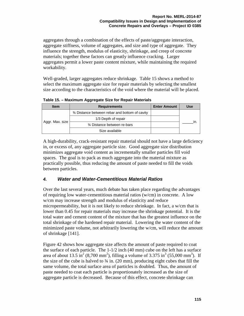
Report No. MERL-2014-87 Compatibility Issues in Design and Implementation of
Concrete Repairs and Overlays – Project ID 0385
aggregates through a combination of the effects of paste/aggregate interaction, aggregate stiffness, volume of aggregates, and size and type of aggregate. They influence the strength, modulus of elasticity, shrinkage, and creep of concrete materials; together these factors can greatly influence cracking. Larger aggregates permit a lower paste content mixture, while maintaining the required workability. Well-graded, larger aggregates reduce shrinkage. Table 15 shows a method to select the maximum aggregate size for repair materials by selecting the smallest size according to the characteristics of the void where the material will be placed. Table 15. – Maximum Aggregate Size for Repair Materials
Item Requirements Enter Amount Use
Aggr. Max. size
¾ Distance between rebar and bottom of cavity
in. 1/3 Depth of repair
¾ Distance between re-bars
Size available A high-durability, crack-resistant repair material should not have a large deficiency in, or excess of, any aggregate particle size. Good aggregate size distribution minimizes aggregate void content as incrementally smaller particles fill void spaces. The goal is to pack as much aggregate into the material mixture as practically possible, thus reducing the amount of paste needed to fill the voids between particles.
4. Water and Water-Cementitious Material Ratios
Over the last several years, much debate has taken place regarding the advantages of requiring low water-cementitious material ratios (w/cm) in concrete. A low w/cm may increase strength and modulus of elasticity and reduce micropermeability, but it is not likely to reduce shrinkage. In fact, a w/cm that is lower than 0.45 for repair materials may increase the shrinkage potential. It is the total water and cement content of the mixture that has the greatest influence on the total shrinkage of the hardened repair material. Lowering the water content of the minimized paste volume, not arbitrarily lowering the w/cm, will reduce the amount of shrinkage [141]. Figure 42 shows how aggregate size affects the amount of paste required to coat the surface of each particle. The 1-1/2 inch (40 mm) cube on the left has a surface area of about 13.5 in2 (8,700 mm2), filling a volume of 3.375 in3 (55,000 mm3). If the size of the cube is halved to ¾ in. (20 mm), producing eight cubes that fill the same volume, the total surface area of particles is doubled. Thus, the amount of paste needed to coat each particle is proportionately increased as the size of aggregate particle is decreased. Because of this effect, concrete shrinkage can
115

Report No. MERL-2014-87 Compatibility Issues in Design and Implementation of Concrete Repairs and Overlays – Project ID 0385 increase by as much as 25 percent when a 3/4-inch (20-mm) maximum-size aggregate is used in lieu of a 1-1/2-inch (40-mm) maximum-size aggregate (6).
Figure 42. – How aggregate size affects the amount of paste required to coat the surface of each particle [34].
5. Mineral Admixtures
Fly ash and slag reduce the rate of strength gain and early hydration temperatures of cement-based materials, and their use is being recommended to reduce the incidence of cracking of repair materials. Replacing cement with mineral admixtures holds promise to reduce early repair stresses and cracking. However, this is not universally true. Use of silica fume, especially in excess of 7 percent of amount of cement, can increases early stresses and cracking if special curing precautions are not taken. Abdun-Nur [142] once stated that “concrete which does not contain fly ash belongs in a museum.” His reasoning was that fly ash adds so many known advantages to concrete that to leave it out means leaving concrete unprotected from a list of hazards, which may lie in other materials or in the environment. While the construction industry finds itself progressing in many areas of endeavor, it can be recalcitrant in requiring fly ash to be added for increased durability. ACI 232.3R-03 [143] is an excellent reference that explains how concrete durability is improved with fly ash. Through its combination with calcium, potassium, and sodium hydroxides to produce calcium silicate hydrates, Class F fly ash reduces permeability (micropermeability), thereby reducing the access of aggressive chemicals, oxygen, and moisture in absence of cracks.
116

Report No. MERL-2014-87 Compatibility Issues in Design and Implementation of
Concrete Repairs and Overlays – Project ID 0385
ACI 318 [144] comments on this under “Corrosion Protection of Reinforcing,” “Use of slag meeting ASTM C989 or fly ash meeting ASTM C618 and increased levels of specified strength provide increased protection.” The problem of ASR (one form of AAR) has been traced to reactive silica aggregates found in many areas of the world. In all but the most reactive aggregates, the silica component of fly ash consumes the available alkalis present in cement and reduces the level of expansion to nondestructive levels. Some forms of ASR occur quickly, while others may take years to occur. Those forms may be undetected by short-term test procedures; therefore, fly ash may offer additional security. With Class F fly ash, sulfate resistance is also improved. In many cases, the Class F fly ash protects the concrete via a mechanism that consumes the excess calcium hydroxide and makes it unavailable for reaction with sulfates.
6. Testing the Sensitivity to Cracking
ASTM C1581 [145], which allows for evaluation of a material’s sensitivity to cracking, is useful for determining the relative likelihood of early material cracking and for aiding in the selection of material mixtures that are less likely to crack. The major advantage of this test is that it accounts for numerous factors that affect shrinkage cracking starting from the time of specimen casting. Unfortunately, this procedure, and others that evaluate shrinkage, is not routinely required for evaluating concrete or concrete repair materials.
7. Summary
Our concern with compatibility should not be based solely on the materials themselves, or with the uses to which they can be put. It should also be on achieving the middle ground, the area of overlap with existing concrete, to obtain a lasting, successful union of materials. Significant advances are still to be made in correctly matching organic polymers and concrete to ensure that this combination of dissimilar materials provides an acceptable long-term service. A better understanding by the engineer/specifier of the fundamental properties of polymer-based materials will help prevent premature failures, lead to greater composite durability, and, therefore, pave the way for innovation in materials and applications. A clearer appreciation is needed of those physical properties that may provide the key to successful and durable use of polymer-based materials in concrete repair. An integral part of this appreciation is the assessment of the likely consequences of the “mismatch” of properties (e.g., CTE, modulus of elasticity, and creep). Furthermore, repair professionals must ensure that the properties required are actually obtainable under the prevailing site conditions. Underlying this
117

Report No. MERL-2014-87 Compatibility Issues in Design and Implementation of Concrete Repairs and Overlays – Project ID 0385 assessment is the further need to make a clear judgment of the relevance of the materials properties test data and the methods used to obtain it. Understanding the differences in properties and their impacts, whether they are cement-based or polymer-based repair materials, is crucial to successful use with the existing substrate. Success or failure of application depends on recognizing and overcoming a potentially destructive mismatch, either by techniques, additives, and/or by the use of an appropriate polymer type. Certain key properties of both the repair material and the substrate must be clearly identified. Failures can often be attributed to an inability to clearly recognize fundamental differences such as the relative strain, rather than the stress tolerance, of a polymer-based material and concrete, an error that occurs frequently. There are always property differences, mismatches between any repair materials, and concrete substrates, which may lead to application and performance problems. The choice of the best material for a given repair application is, of necessity, a balancing act between material properties, exposure conditions, substrate conditions, budget constraints, etc. Selection should always be based on as much knowledge of the relevant properties as possible. Compatibility and durability design of repair systems does not need to involve calculations comparable with those for structural design and safety. In this context, design does not equate to analysis. Rather, much more emphasis falls upon both conceptual design (in developing an adherent defensive strategy) and on specifications and design details because they can simplify and improve construction, while resisting deleterious transport mechanisms and the risk of premature failure.
B. Permeability Compatibility
Permeability compatibility is a critical issue. The majority of repair publications strongly recommend using materials that have permeability values as low as possible in repair systems. Currently, permeability of a small material sample is measured according to ASTM C1202, “Standard Test Method for Electrical Indication of Concrete’s Ability to Resist Chloride Ion Penetration.” [72]. This test is applicable for laboratory use only; in real-life structures, it only measures permeability between cracks. A few cracks in the repair will drastically offset the benefit of having a low permeability repair material. Cracks and microcracks originating from the repair surface play a much greater role in reducing the impermeability and longevity than the permeability of the repair material itself. Permeability of repair materials is one of the primary properties of importance, and engineering analysis and judgment are needed to define what degree of
118

Report No. MERL-2014-87 Compatibility Issues in Design and Implementation of
Concrete Repairs and Overlays – Project ID 0385
permeability of repair materials should be recommended for different repair situations. Most likely, no single recommendation exists to determine whether very low permeability materials, or compatible permeability materials, are more effective with existing concrete. It depends on the particular transport mechanisms in the repair system. Transport of substances through and in the repair systems is a very complex process, consisting of a combination of liquid flow through macrocrack and microcrack systems, capillary transport, diffusion, and osmotic effects. The exact contribution of each process needs to be quantified in each particular situation. The effects of such variables as location of the repair in the structure, chemical environment in the composite repair system, amount and distribution of cracks in both phases, temperature, moisture, and stresses need to be considered.
C. Electrochemical Compatibility
Achieving electrochemical compatibility in repaired structures is a very difficult, if not impossible, task. The majority of repairs involving corrosion of embedded reinforcement can disrupt the electrochemical stability of the steel in the existing structure. In addition, only a small part of the structure is being repaired (the area that first displays damage). To meet long-term durability requirements, the inherent vulnerability of the steel reinforcement and existing concrete repair composite system must be analyzed and considered. When an existing concrete structure suffers from corrosion of reinforcement and concrete deterioration, it means that steel is depassivated, and an essential cathodic reaction is taking place in the structure. Usually, only several areas of such a structure are exhibiting corrosion damage and are being repaired. Replacement of the most intensely anodic regions of the reinforcement with passive steel in the repair areas removes the potential sacrificial cathodic protection that was applied to the steel in the neighboring nonrepaired regions prior to repair. The corrosion process in the structures is not halted; it is ongoing. The risk of continuing corrosion, or even its acceleration, due to the electrochemical incompatibility between “old” and “new” is always present unless global cathodic protection is specified. The synergistic effects of several critical diverse environments that are present along the electrically continuous reinforcement, in addition to the differentials in stress states, significantly add to the complexity of the problem. The influence of the repair phase on the existing phase, change in chemical composition, distribution of aggressive agents, oxygen, moisture, and other factors on the electrochemical properties of the repair system all need to be considered. However, no guidance currently exists for doing so, which is why it is very rare for a successful repair of a corrosion-affected structure to last for longer than 10-15 years without problems.
119

Report No. MERL-2014-87 Compatibility Issues in Design and Implementation of Concrete Repairs and Overlays – Project ID 0385 D. Durability Design
In order to achieve the optimum service life extension of a repaired structure, condition evaluation and durability planning prior to developing detailed designs and specifications are of critical importance. Concrete repair is always an open-ended, approximate solution; however, it must be an approximate solution to an exact problem [5]. Unfortunately, many times, repair projects are approximate solutions to approximate problems due to an inadequate condition evaluation. A durable repair project cannot be successfully designed if the repair practitioner does not know precisely what the problems are, how extensive they are, and what has caused their occurrence. Establishing the cause(s) of the problem is difficult, due to the following three main factors: (1) no two repair cases are ever identical, so every case should be analyzed and judged on its own merits; (2) there is frequently an inadequate understanding of electrochemical behavior of steel exposed to various environments; and (3) the recognition that poor performance usually results from the combined effect of several factors. Many times, these factors interact to increase degradation, but it can be difficult to determine which factor caused the initial damage. Those who design the condition evaluation program, as well as those who perform the condition evaluation, should be knowledgeable and experienced in this field in five specific ways, which include:
1. Thorough knowledge of the structure and materials being evaluated;
2. Knowledge of how to use the available testing methods in practice and how to operate the equipment;
3. Knowledge of the limitation of the test methods;
4. Ability to properly interpret the data collected and understand the significance;
5. Ability to clearly and reliably establish the cause of the deterioration or distress problems.
The internal environmental condition in the existing structure and the prevailing transport processes need to be determined during the condition evaluation. Without that knowledge, determining possible deterioration and transport processes in a new composite repair system would be impossible. The basic rule of thumb is that reducing transport processes will normally reduce the electrochemical incompatibility and prolong the useful service life of the repaired structure. After the exact problem(s) and their extent are properly identified, durability planning can begin. Typically, there are six main stages:
120

Report No. MERL-2014-87 Compatibility Issues in Design and Implementation of
Concrete Repairs and Overlays – Project ID 0385
1. Assessment of the condition evaluation results;
2. Analysis of the consequences of continued deterioration to structure, performance, structural risk, and economic issues;
3. Mathematical modeling and experience-based considerations of future service life;
4. Establishing performance requirements and project objectives;
5. Recommended remedial options (alternative solutions) to meet the project objectives;
6. Life-cycle cost analysis. Figure 43 is a flowchart that presents a suggested durability design of a repair project.
Figure 43. – Flowchart of a durability design [73].
121

Report No. MERL-2014-87 Compatibility Issues in Design and Implementation of Concrete Repairs and Overlays – Project ID 0385 In conclusion, by following these steps, the repair professional and the structure owner can accomplish the best outcome for the repair project.
122

Report No. MERL-2014-87 Compatibility Issues in Design and Implementation of
Concrete Repairs and Overlays – Project ID 0385
References [1] Bates, A.A. (1966). Selected Technical Papers 169-A, Significance of
Tests and Properties of Concrete and Concrete-Making Materials, 55-57. American Society for Testing and Materials.
[2] Vaysburd, A.M., Emmons, P.H., and Bissonnette, B. (2010). Concrete
Repair: “Compatibility” Demystified. International Journal of 3R's, 1(2), 68-73.
[3] Vaysburd, A.M., and Emmons, P.H. (2006). Concrete Repair: A
Composite System: Philosophy, Engineering and Practice. International Journal for Restoration of Buildings and Monuments, 12(5/6), 423-435.
[4] Matthews, S.L. (2007). Achieving Durable Repaired Concrete Structures.
Watford, UK: BRE Press. [5] Vaysburd, A.M., Emmons, P.H., and Bissonnette, B. (2012). Concrete
Repair as an Engineering Task: An Approximate Solution to an Exact Problem. Proceedings of the International Conference on Concrete Repair, Rehabilitation and Retrofitting. Cape Town, South Africa.
[6] Emmons, P.H., and Vaysburd, A.M. (1995, April). Performance Criteria
for Concrete Repair Materials – Phase I. Technical Report REMR-CS-47, 130 pp. U.S. Army Corps of Engineers.
[7] Emmons, P.H., and Vaysburd, A.M. (1993). Factors Affecting Durability
of Concrete Repair – The Contractor's Viewpoint. Proceedings of the Fifth International Conference on Structural Faults and Repair, 253-268. Edinburgh, UK.
[8] Vaysburd, A.M. (2006, September). Holistic System Approach to Design
and Implementation of Concrete Repairs. Cement and Concrete Composites, 28(8), 671-678.
[9] Mehta, P.K. (1991). Durability of Concrete – Fifty Years of Progress?
Proceedings of the Second International Conference on Durability of Concrete, 1-31. Montreal, Canada: ACI SP-126. American Concrete Institute.
[10] Vaysburd, A.M., Sabnis, G.M., Emmons, P.H., and McDonald, J.E.
(2001, January). Interfacial Bond and Surface Preparations in Concrete Repairs. Indian Concrete Journal, 75(1), 27-33.
123

Report No. MERL-2014-87 Compatibility Issues in Design and Implementation of Concrete Repairs and Overlays – Project ID 0385
[11] Vaysburd, A.M. (2006). Durability of Repaired Concrete Structures –
The Battle for Survival. Proceedings of the Second International Symposium on Advances in Concrete through Science and Engineering, 207-224. Quebec City, Canada.
[12] Plum, D.R. (1991, July/August). Material – What to Specify.
Construction Maintenance and Repair. [13] Mays, G., and Wilkinson, W. (1987). Polymer Repairs to Concrete:
Their Influence on Durability of Concrete. ACI SP-100, 1, 351-375. American Concrete Institute.
[14] Emmons, P.H., Vaysburd, A.M., and McDonald, J.E. (1994, March). Concrete Repair in the Future Turn of the Century – Any Problems? Concrete International, 16(3), 42-49.
[15] Emmons, P.H. (1993). Concrete Repair and Maintenance Illustrated:
Problem Analysis, Repair Strategy, Techniques. R.S. Means Co., 295 pp. [16] Emmons, P.H., and Vaysburd, A.M. (1993). Compatibility
Considerations for Durable Concrete Repairs. Transportation Research Board Record No. 1382, Materials and Construction, 13-19.
[17] Bronowski, Jacob. (1958). Science and Human Values. Julian Messner,
Inc. [18] Emmons, P.H., McDonald, J.E., and Vaysburd, A.M. (1993). Some
Compatibility Problems in Repair of Concrete Structures – A Fresh Look. Proceedings of the Third International Colloquium on Material Science and Restoration, 836-857. Esslingen, Germany.
[19] Courard, L., and Bissonnette, B. (2007). Compatibility Performance as a
Fundamental Requirement for the Repair of Concrete Structures with Self-Compacting Repair Mortars. Proceedings of the RILEM Conference SCC-2007. Ghent, Belgium.
[20] Hewlett, P.C. (1993). Concrete: The Material of Opportunity. Concrete
2000, Dhir, R.K. and Jones, M.R. (Eds.), 1, 1-22. London: E. and F.N. Spon.
[21] Skalny, J.P., and Young, J.F. (1980). Mechanisms of Portland Cement
Hydration. 7th International Congress on Chemistry of Cement, 1, p. 45. Paris, France.
124
Report No. MERL-2014-87 Compatibility Issues in Design and Implementation of
Concrete Repairs and Overlays – Project ID 0385
[22] Vaysburd, A.M., Bissonnette, B., and Brown, C.D. (2009, January). Compatibility and Concrete Repair. The Construction Specifier, 62(1), 44-53.
[23] Hewlett, P.C., and Hurley, S.A. (1985). The Consequences of
Polymer-Cement Mismatch. Design Life of Buildings, 179-186. London: Thomas Telford.
[24] Emberson, N.K., and Mays, G.C. (1987). Polymer Mortars for the Repair
of Structural Concrete: The Significance of Property Mismatch. Proceedings of ICPIC 87, 5th International Congress on Polymers in Concrete, 235-242. Brighton, England.
[25] Plum, D.R. (1989). Repair Materials and Repaired Structures in Varying
Environments. Proceedings of the 3rd International Seminar on the Life of Structures – The Role of Physical Testing. Brighton, England.
[26] Wood, J.G., King, E.S., and Leek, D.S. (1989). Defining the Properties
of Concrete Repair Materials for Effective Structural Application. Proceedings, Structural Faults and Repair, 89(2), 231-236. London, England.
[27] National Institute of Standards and Technology (NIST). (1999). Polymer
Composites for Repairing Portland Cement Concrete: Compatibility Project. National Institute of Standards and Technology Interagency or Internal Report (NISTIR), 6394, 84 pp.
[28] Mehta, P.K., and Monteiro, P.J. (1993). Concrete: Structure, Properties
and Materials (2nd ed.). Prentice Hall. [29] Domone, P.L. (1974, September). Uniaxial Tensile Creep and Failure of
Concrete. Magazine of Concrete Research, 26(88), 144-152. [30] Hsu, T.T., and Slate, F.D. (1963, April). Tensile Bond Strength Between
Aggregate and Cement Paste or Mortar. ACI Journal Proceedings, 60(4), 465-486.
[31] Tassios, T.P. (1996). Structural Design and Concrete Technology:
Divorce or Symbiosis. Proceedings of the Mario Collepardi Symposium on Advances in Concrete Technology, Mehta, P.K. (Ed.).
[32] U.S. Army Corps of Engineers (USACoE). (1992, December). CRD-C
164-92 – Standard Test Method for Direct Tensile Strength of Cylindrical Concrete or Mortar Specimens, 4 pp.
125
Report No. MERL-2014-87 Compatibility Issues in Design and Implementation of Concrete Repairs and Overlays – Project ID 0385 [33] Price, W.H. (1951). Journal of American Concrete Institute.
Proceedings, 47, p. 429. [34] Vaysburd, A.M. (2004, May). Development of Crack Resistant Durable
Repair Material for Navy Concrete Structures. Navy Small Business Innovation Research Project No. N03-035. Conproco Corporation Technical Report, 65 pp. Portsmouth, New Hampshire.
[35] American Concrete Institute. (2014, June). ACI 546.3R-14 – Guide to
Materials Selection for Concrete Repair, 76 pp. [36] Neville, A.M., Dilger, W.H., and Brooks, J.J. (1983). Creep of Plain and
Structural Concrete. England: Longman. 361 pp. [37] Neville, A.M. (1995). Properties of Concrete. Fourth Edition. Essex,
England: Longham. [38] Aïtcin, P.C., Neville, A.M., and Acker, P. (1997, September). Integrated
View of Shrinkage Deformation. Concrete International, 19(9), pp. 35-41.
[39] American Concrete Institute. (2013, January). ACI CT-13 – ACI
Concrete Terminology, 78 pp, [40] Mehta, P.K. (1996). Volume Change. ASTM Selected Technical Papers
169C, 219-228. American Society for Testing and Materials. [41] Ishai, O. (1965). The Time Dependent Deformation Behavior of
Concrete Paste, Mortar, and Concrete. Proceedings of the International Conference on the Structure of Concrete and its Behavior Under Load, 345-364. London, England.
[42] Smadi, M.M., Slate, F.O., and Nilson, A.H. (1987). Shrinkage and Creep
of High-, Medium-, and Low-Strength Concrete, Including Overloads. ACI Materials Journal, 84(3), 224-234.
[43] Powers, T.C. (1959). Causes and Control of Volume Change. Journal of
Portland Cement Association Research Laboratories, (1), 29-39. [44] Tremper, B., and Spellman, D.L. (1963). Shrinkage of Concrete—
Comparison of Laboratory and Field Performance. Highway Research Record, (3).
[45] Whiting, D. (1979). Effects of HRWR on Some Properties of Fresh
and Hardened Concrete. Research and Development Bulletin No.
126

Report No. MERL-2014-87 Compatibility Issues in Design and Implementation of
Concrete Repairs and Overlays – Project ID 0385
RD-061.01T. Skokie, Illinois: Portland Cement Association.
[46] Gordon, J.E. (1976). The New Science of Strong Materials, or Why You Don’t Fall Through the Floor. Princeton University Press.
[47] L'Hermite, R.G. (1947). Le Retrait des Ciments et Bétons. [48] Noble, P.M. (1931). The Effect of Aggregate and other Variables on
the Elastic Properties of Concrete. Proceedings. ASTM-31, Part 1, pp. 399-426. American Society for Testing and Materials.
[49] Philleo, R. (1956). Elastic Properties and Creep. ASTM Selected
Technical Papers 169-A, Concrete and Concrete Making Materials, 160-175. American Society for Testing and Materials.
[50] Mindess, S., and Young, J.F. (1981). Concrete, Prentice-Hall, Englewood
Cliffs, NJ. [51] Woolson, I. (1905). Some Remarkable Tests Indicating Flow of Concrete
Under Pressure. Engineering News, 454. [52] Troxell, G.E., Raphael, J.E., and Davis, R.W. (1958). Long-Time Creep
and Shrinkage Tests of Plain and Reinforced Concrete, ASTM Proceedings, 1101-1120. American Society for Testing and Materials.
[53] Lea, F., and Lee, C. (1947). Shrinkage and Creep, Concrete Symposium
of Shrinkage Cracking of Cementitious Materials. The Society of Chemical Industry, 17-22.
[54] Hanson, T. (1958). Creep of Concrete. Swedish Cement and Concrete
Institute of Technology. [55] Freyssinet, E. (1951). The Deformation of Concrete. Magazine of
Concrete Research, (3)8, 49-56. [56] Torroga, E., and Paez, A. (1954). Chapter 8 – Building Materials,
Their Elasticity and Plasticity. Set Concrete and Reinforced Concrete, 290-360. Amsterdam: North Holland Publishing Company.
[57] Smadi, M. (1982). Time-Dependent Behavior of High-Strength Concrete
under High Sustained Compressive Stress. Ithica, New York: Department of Structural Engineering, Cornell University.
[58] Kelly, J.W. (1963, June) Presentation at the Associated General
Contractor’s meeting in San Francisco (CA).
127

Report No. MERL-2014-87 Compatibility Issues in Design and Implementation of Concrete Repairs and Overlays – Project ID 0385 [59] Vaysburd, A.M., Emmons, P.H, and Sabnis, G.M. (1997, December).
Minimizing Cracking – The Key to Durable Concrete Repairs. The Indian Concrete Journal.
[60] Bissonnette, B., and Pigeon, M. (1995). Tensile Creep at Early Ages of
Ordinary, Silica Fume and Fiber Reinforced Concrete. Cement and Concrete Research, 25(5), 1075-1085.
[61] Bissonnette, B., Pigeon, M., and Vaysburd, A.M. (2007). Tensile Creep
of Concrete: Study of its Sensitivity to Basic Parameters. ACI Materials Journal, 104(68), 360-368.
[62] Sprinkel, M.M. (1983). Thermal Compatibility of Thin Polymer Concrete
Overlays. Transportation Research Board Record No. 899. [63] Hanley, B., Coverdale, T., Miltenberger, M.A., and Nmai, C.K.
(1998, May/June). Electrochemical Compatibility in Concrete Repair. Concrete Repair Bulletin, 12-15.
[64] Schrader, E.K., and Kaden, R.A. (1987, April). Durability of Shotcrete.
ACI SP100-57, Katherine and Bryant Manther International Conference on Durability of Concrete, 2, 1071-1102. American Concrete Institute.
[65] Mehta, P.K., and Gerwick, B.C. (1982, October). Cracking-Corrosion
Interaction in Concrete Exposed to Marine Environment. Concrete International, 4(10), 45-51.
[66] Detwiler, R.J. (1996). Microstructure and Mass Transport in Concrete.
In K. Saki (Ed.), Integrated Design and Environmental Issues in Concrete Technology. London: E.&F.N. Spon.
[67] Valenta, O. (1968). Durability of Concrete. Proceedings of the Fifth
International Symposium on the Chemistry of Cements, 3, 193-225. Tokyo, Japan.
[68] Vaysburd, A.M., and Emmons, P.H. (2001, January). Visible and
Invisible Problems of Concrete Repair. Indian Concrete Journal, 75(1), 13-24.
[69] Vaysburd, A.M., and Emmons, P.H. (2000). How to Make Corrosion
Protection in Concrete Repair. Construction and Building Materials, 14(4), 189-197.
128

Report No. MERL-2014-87 Compatibility Issues in Design and Implementation of
Concrete Repairs and Overlays – Project ID 0385
[70] Alekseev, S.N., and Rosenthal, N.K. (1976). Resistance of Reinforced Concrete in Industrial Environment. Moscow: Stroyisdat.
[71] Vaysburd, A.M. (2005). Repairing Concrete: Random Thoughts on
Concrete Ills and Treatment Prescriptions. Advances in Corrosion Repair of Concrete Structures, International Journal of Materials and Product Technology, 23(3/4), 164-176.
[72] American Society for Testing and Materials. (2012). ASTM C1202-12 –
Standard Test Method for Electrical Indication of Concrete’s Ability to Resist Chloride Ion Penetration, 7 pp.
[73] Vaysburd, A.M., Emmons, P.H., and Bissonnette, B. (2009). Concrete
Repair: Research and Practice – The Critical Dimension. Concrete Repair, Rehabilitation and Retrofitting II, Alexander, M., Beushausen, H.D., Dehn, F., Moyo, P. (Eds.), 717-724. London : Taylor & Francis Group.
[74] Zhang, M.H., and Gjørv, O.E. (1991). Permeability of High Strength
Lightweight Concrete. ACI Materials Journal, 88(5), 463-469.
[75] Buenfeld, N.R., and Newman, J.B. (1987, January). Examination of Three Methods for Studying Ion Diffusion in Cement Pastes, Mortars, and Concrete. Materials and Structures Research and Testing, RILEM, 20(15), 3-10.
[76] Brophy, J.H., Rose, R.M., and Nulff, J. (1964). Structures and Properties
of Materials. In Thermodynamics of Structures, Vol. 2, 75-97. New York: John Wiley and Sons.
[77] Shi, C., Stegemann, J.A., and Caldwell, R.J. (1998, July/August). Effect
of Supplementary Cementing Materials on the Specific Conductivity of Pore Solution and its Implications on the Rapid Chloride Permeability Test (AASHTO 227 and ASTM C1202) Results. ACI Materials Journal 95(4), 389-394.
[78] [78] Gu, P., Beaudoin, J.J., Tumidajski, P.J., and Mailvaganam, N.P.
(1997, August). Electrochemical Incompatibility of Patches in Reinforced Concrete. Concrete International 19(8), 68-72.
[79] Emmons, P.H., and Vaysburd, A.M. (1997, March). Corrosion Protection
in Concrete Repair: Myth and Reality. Concrete International 19(3), 47-56.
129
Report No. MERL-2014-87 Compatibility Issues in Design and Implementation of Concrete Repairs and Overlays – Project ID 0385 [80] Zhang, J., and Mailvaganam, N.P. (2006). Corrosion of Concrete
Reinforcement and Electrochemical Factors in Concrete Patch Repair. Canadian Journal of Civil Engineering, 33: 785-793.
[81] RILEM TC 124-SRC. (1994). Draft Recommendation for Repair
Strategies for Concrete Structures Damaged by Reinforcement Corrosion, Materials and Structures, 27(171), 415-436.
[82] Pruckner, F., and Gjørv, O.E. (2002, March). Patch Repair Macrocell
Activity in Concrete Structures. ACI Materials Journal, 99(2), 143-148. [83] Castro, P., Pazini, E., Andrade, C., and Alonso, C. (2003, June).
Macrocell Activity in Slightly Chloride-Contaminated Concrete Induced by Reinforcement Primers. Corrosion, 59(6), 535-546.
[84] Cusson, D., Hoogaveen, T., and Qian, S. (2004, June). Field Performance
Monitoring and Evaluation of Concrete Repair Systems on a Highway Bridge. 5th Structural Specialty Conference of the Canadian Society for Civil Engineers, ST-198 – 1-10. Saskatoon, Canada.
[85] Andrade, C., Maribona, I.R., Feliu, S., Gonzalez, J.A., and Feliu, S.Jr.
(1992, February). The Effect of Macrocells Between Active and Passive Areas of Steel Reinforcements. Corrosion Science, 33(2), 237-249.
[86] Raupach, M. (1996, July). Chloride-Induced Macrocell Corrosion of
Steel in Concrete – Theoretical Background and Practical Consequences. Construction and Building Materials, 10(5), 329-338.
[87] Schiesl, P., and Breit, W. (1996). Local Repair Measures at Concrete
Structures Damaged by Reinforcement Corrosion-Aspect of Durability. International Symposium on Corrosion of Reinforcement in Concrete Construction, 327-336. Royal Society of Chemistry, SP-183.
[88] Li, G., and Yuan, Y.S. (2003). Electrochemical Incompatibility for
Patch-Repaired Corroded Reinforced Concrete. Journal of China University of Mining and Technology, (32), 44-47.
[89] Barkey, D.P. (2004, July). Corrosion of Steel Reinforcement in Concrete
Ajacent to Surface Repairs. ACI Materials Journal, 101(4), 266-272. [90] Vaysburd, A.M., and Emmons, P.H. (2004, April). Corrosion Inhibitors
and Other Protective Systems in Concrete Repair: Concepts or Misconcepts. Cement and Concrete Composites, 26(3), 255-263.
130

Report No. MERL-2014-87 Compatibility Issues in Design and Implementation of
Concrete Repairs and Overlays – Project ID 0385
[91] Sprinkel, M.M. (2003, June). Evaluation of Corrosion Inhibitors for Concrete Bridge Deck Patches and Overlays. Virginia Transportation Research Council, VTRC 03 R14, 33 pp.
[92] Slater, D., and Sharp, B.N. (1998). Specifications for Marine Structures:
Mythology or Methodology. Proceedings of the International Workshop on Rational Design of Concrete Structures under Severe Conditions, 46-49. Japan.
[93] Forgey, C. (2005, June). Changing the Color of Concrete. Concrete
International, 27(6), 78-81. [94] Vaysburd, A.M., Emmors, P.H., Mailvaganam, N.P., McDonald, J.E., and
Bissonnette, B. (2004). Concrete Repair Technology: A Revised Approach is Needed. Concrete International, 26(1), 58-65.
[95] Plum, D.R. (1990, September). The Behavior of Polymer Materials in
Concrete Repair, and Factors Influencing Selection. The Structural Engineer, 68(17), 337-344.
[96] Krauss, P.D., and Rogalla, E.A. (1996). Transverse Cracking in Nearly
Constructed Bridge Decks. National Cooperative Highway Research Program Report.
[97] Vaysburd, A.M, Emmons, P.H., McDonald, J.E., Poston, R.W., and
Kesner, K. (1998). Performance Criteria for Concrete Repair Materials – Summary Report. REMR-CS-62. USACoE, Vicksburg (MS), 73 pp.
[98] Vaysburd, A.M., and Emmors, P.H. (1999). Performance Criteria for
Selection of Repair Materials. Fifth International Conference on Durability of Concrete. Barcelona.
[99] McDonald, J.E., Vaysburd, A.M., and Poston, R.W. (1999). Performance
Criteria for Dimensionally Compatible Repair Materials. International Conference of Infrastructure Regeneration and Rehabilitation: A Vision for the Next Millenium. Sheffield.
[100] Goodwin, F.R., Van Garven, R. (2010). International Concrete Repair
Institute (ICRI) 320.3, Repair Material Data Sheet Protocol: Going from Good to Better. Concrete Repair Bulletin, July/August.
[101] International Concrete Repair Institute. (2012). ICRI 320.3, Guide for
Inorganic Repair Material Data Sheet Protocol, 13 pp.
131

Report No. MERL-2014-87 Compatibility Issues in Design and Implementation of Concrete Repairs and Overlays – Project ID 0385 [102] American Concrete Institute. (2009). ACI 364 3R-09 – Guide for
Cementitious Material Data Sheet, 16 pp. [103] Snover, R.M., Vaysburd, A.M., and Bissonnette, B. (2011, December).
Concrete Repair Specifications: Guidance or Confusions? Concrete International, 33(12), 57-63.
[104] Burke, D.F., Brown, C.D., Bissonnette, B., and Vaysburd, A.M. (2006). Roadmap for Improvement of Crack Resistance of Repair Materials. Concrete Repair, Rehabilitation and Retrofitting, Alexander, M., Beushausen, H.D., Dehn, F., Moyo, P. (Eds.), 371. London : Taylor & Francis Group.
[105] Beushausen, H.D. (2005, February). Long-Term Performance of Bonded
Concrete Overlays Subjected to Differential Shrinkage. Ph.D. Thesis, University of Cape Town, South Africa.
[106] RILEM Technical Committee 193-RLS. (2011). Bonded cement-based
material overlays for the repair, the lining or the strengthening of slabs or pavements, 186 pp. Bissonnette, B., Courard, L., Fowler, D.W., Granju, J.-L. (Eds.). RILEM State-of-the-Art Reports, Vol. 3.
[107] Courard, L. (1999). How to Analyze Thermodynamic Properties of
Solids and Liquids in Relation with Adhesion. Proceedings of the 2nd International RILEM Symposium, International Society of Asphalt Pavements, 99, pp. 9-19.
[108] Fiebrich, M. (1994). Grundlagen der Adhasionskunde. German
Association for Reinforced Concrete, Heft 334, pp. 75-90. Berlin, Germany.
[109] Tassios, T.P., and Vintzeleou, E.N. (1987, April). Concrete to Concrete
Friction. Journal of Structural Engineering, 113(4), 832-849. [110] Walraven, J.C., and Stroband, J. (1994). Shear Friction in High-Strength
Concrete. Proc. ACI Conference on High-Strength Concrete, ACI SP149-17, pp. 57-65. Singapore.
[111] Bissonnette, B., Vaysburd, A.M., and Von Fay, K.F. (2012). Best
Practices for Preparing Concrete Surfaces Prior to Repairs and Overlays. Report MERL 12-17, 92 pp. Bureau of Reclamation, Denver, Colorado.
[112] Talbot, C., Pigeon, M., Beaupré, D., and Morgan, D.R. (1995,
November). Influence of Surface Preparation on Long-Term Bonding of Shotcrete. ACI Materials Journal, 91(6), 560-566.
132

Report No. MERL-2014-87 Compatibility Issues in Design and Implementation of
Concrete Repairs and Overlays – Project ID 0385
[113] Courard, L. (2000, January/February). Parametric Study for the Creation
of Interface between Concrete and Repair Products. Materials and Structures, 33(225), 65-72.
[114] Pigeon, M., and Saucier, F. (1992). Durability of Repaired Concrete
Structures. Proceedings of the International Symposium on Advances in Concrete Technology, pp. 741-773. Athens, Greece.
[115] Van Mier, J.G. (1996, December). Fracture Processes in Concrete, CRC
Press, 464 pp. [116] Misra, A., Cleland, D.J., and Basheer, P.A.M. (2001). Effect of Different
Substrate and Overlay Concretes on Bond Strength and Interfacial Permeability. Concrete Science and Engineering, 3(10), 73-77.
[117] Candon, A.H., and Hiel, C.C. (1986). Durability Analysis of Adhesive
Joints. RILEM Symposium on Resin Adherence in Concrete, 3-7. Paris, France.
[118] Li, S.E., Geissert, D.G., Frantz, G.C., and Stephens, J.E. (1999,
March/April). Freeze-Thaw Bond Durability of Rapid Setting Concrete Repair Materials. ACI Materials Journal, 96(2), 242-249.
[119] Silfwerbrand, J. (2003, July). Shear Bond Strength in Repaired Concrete
Structures. Materials and Structures, 36(6), 419-424. [120] Delatte, N.J, Williamson, M.S., and Fowler, D.W. (2000, June). Bond
Strength Development of High-Early-Strength Bonded Concrete Overlays. ACI Materials Journal, 97(2), 201-207.
[121] Vaysburd, A.M., and McDonald, J.E. (1999, May). An Evaluation of
Equipment and Procedures for Tensile Bond Testing of Concrete Repairs. Technical Report REMR-CS-61, REMR Program, U.S. Army Corps of Engineers, WES, 85 pp.
[122] Zhu, Y. (1992). Effect of Surface Moisture Condition on Bond Strength
Between New and Old Concrete. Bulletin No. 159, Department of Structural Mechanics, Royal Institute of Technology, Stockholm.
[123] Courard, L., Degeimbre, R., Darimont, A., and Wiertz, J. (1999). Effects
of Sunshine/Rain Cycles on the Behaviour of Repair Systems. Proceedings of the 2nd International RILEM Symposium on Adhesion between Polymers and Concrete, International Society of Asphalt
133

Report No. MERL-2014-87 Compatibility Issues in Design and Implementation of Concrete Repairs and Overlays – Project ID 0385
Pavements (ISAP) 99, Ohama, Y., and Puterman, M. (Eds.), 511-521. Dresden.
[124] Courard, L., Degeimbre, R., Darimont, A., and Wiertz, J. (2003).
Hygro-thermal Application Conditions and Adhesion. Proceedings of the Fifth International Colloquium on Industrial Floors, Seidler, P. (Ed.), 137-142. Ostfildern/Stuttgart: Technische Akademie Esslingen.
[125] Courard, L., and Darimont, A. (1998). Appetency and Adhesion:
Analysis of the Kinetics of Contact Between Concrete and Repairing Mortars. Proceedings of the RILEM International Conference, Interfacial Transition Zone in Cementitious Composites, Katz, A., Bentur, A., Alexander, M.G., and Arliguie, G. (Eds.), 185-194. Haïfa: E.&F.N. Spon.
[126] Schrader, E.K. (1992). Mistakes, Misconceptions, and Controversial
Issues Concerning Concrete and Concrete Repairs, Part 2. Concrete International, 14(10), 48-52.
[127] Schrader, E.K. (1992). Mistakes, Misconceptions, and Controversial
Issues Concerning Concrete and Concrete Repairs, Part 3. Concrete International, 14(11), 54-59.
[128] Gulyas, R.J., Wirthlin, G.J., and Champa, J.T. (1995, January/February).
Evaluation of Keyway Grout Test Methods for Precast Concrete Bridges. PCI Journal, 40(1), 44-57.
[129] Block, K., and Porth, M. (1989). Spritzbeton auf Carbonatisertem Beton.
Beton (7), 299-302. [130] Lacombe, P., Beaupré, D., and Pouliot, N. (1999, October). Rheology
and Bonding Characteristics of Self-Leveling Concrete as a Repair Material. Materials and Structures, 32(222), 593-600.
[131] Atzeni, C., Massidda, L., and Sanna, U. (1993). Dimensional Variations,
Capillary Absorption and Freeze-Thaw Resistance of Repair Mortars Admixed with Polymer. Cement and Concrete Research, 23(2), 301-308.
[132] Li, G. (2003, June). A New Way to Increase the Long-Term Bond
Strength of New-to-Old Concrete by the Use of Fly Ash. Cement and Concrete Research, 33(6), 799-806.
[133] Kuroda, M., Watanabe, T., and Terashi, N. (2000, February). Increase of
Bond Strength at Interfacial Transition Zone by Use of Fly Ash. Cement and Concrete Research, 30(2), 253-258.
134

Report No. MERL-2014-87 Compatibility Issues in Design and Implementation of
Concrete Repairs and Overlays – Project ID 0385
[134] Delatte, N.J., Wade, D.M., and Fowler, D.W. (2000, May/June).
Laboratory and Field Testing of Concrete Bond Development for Expedited Concrete Overlays. ACI Materials Journal, 97(3), 272-280.
[135] Silfwerbrand, J. (1992). The Influence of Traffic-Induced Vibrations on
the Bond Between Old and New Concrete. Bulletin No. 158, Department of Structural Mechanics, Royal Institute of Technology. Stockholm.
[136] Carter, P., Gurjar, S., and Wong, J. (2002, July). Debonding of Highway
Bridge Deck Overlays. Concrete International, 24(7), 51-58. [137] Langlois, M., Pigeon, M., Bissonnette, B., and Allard, D. (1994, August).
Durability of Pavement Repairs: A Field Experiment. Concrete International, 16(8), 39-43.
[138] Souza, R.H.F., and Appleton, J. (2003). Assessing the Structural
Performance of Repaired Concrete Members. International Conference on Performance of Construction Materials, 11 pp. Cairo.
[139] Okada, K., Koyanagi, W., and Yoshioka, Y. (1970). Study on the
Differential Shrinkage of Composite Concrete Beams. Symposium on Design of Concrete Structures for Creep, Shrinkage, and Temperature Changes, Report of the Working Commissions, 5, 46-74. Madrid, Spain.
[140] American Society for Testing and Materials. (2009). ASTM C876-09 –
Standard Test Method for Corrosion Potentials of Uncoated Reinforcing Steel in Concrete, 7 pp.
[141] Harrison, P.J. (2004, September). For the Ideal Slab-on-Grade Mixture.
Concrete International, 26(3), 49-55. [142] Abdun-Nur, E.A. (1962, January). How Good is Good Enough? ACI
Journal Proceedings, 59(1), 31-46. [143] American Concrete Institute. (2003). ACI 232.R-03 – Use of Fly Ash in
Concrete, 41 pp. [144] American Concrete Institute. (2008). ACI 318-08 – Building Code
Requirements for Structural Concrete (ACI 318-08) and Commentary, 479 pp.
[145] American Society for Testing and Materials. (2004). ASTM C1581 /
C1581M - 09a – Standard Test Method for Determining Age at Cracking
135

Report No. MERL-2014-87 Compatibility Issues in Design and Implementation of Concrete Repairs and Overlays – Project ID 0385
and Induced Tensile Stress Characteristics of Mortar and Concrete under Restrained Shrinkage, 7 pp.
136